

Page 1

BU1203MC/MCF
Users Guide
Rev.1.20
Doc. No. 4300-0223
December 25th 2015
Copyright © 2015 TOSHIBA TELI CORPORATION, All rights reserved.
Page 2

On the subject of this document
This document is to introduce the development source and
technical source tackled by TOSHIBA TELI CORPORATION.
This article information described in this document contains
an under development source and subject to change
without notice.
Please read operation manual carefully before you use the
product at the first time, and use it properly. Product
specifications, operation manual and other related
documents are available in our HP to download. Please keep
these materials in your hand so that you can read them at
any time.
http://www.toshiba-teli.co.jp/en/products/industrial/
Please refer our HP or contact our sales person for your
enquiry and the latest information.
* Some of the names and logos of company, organization, standard might be registered trade mark of each.
Doc. No. 4300-0223
2015/12/25
2 Copyright © 2015 TOSHIBA TELI CORPORATION, All rights reserved.
Page 3
Table of Contents
Product range of USB3 Vision cameras
Advantage of BU1203MC/MCF
Spec comparison
Feature comparison
Advanced function
Related documents
[Appendix] Shutter function
Introduction of USB3.0
Doc. No. 4300-0223
2015/12/25
3 Copyright © 2015 TOSHIBA TELI CORPORATION, All rights reserved.
Page 4
USB3 Vision Camera
Product Range
Doc. No. 4300-0223
2015/12/25
4 Copyright © 2015 TOSHIBA TELI CORPORATION, All rights reserved.
Page 5
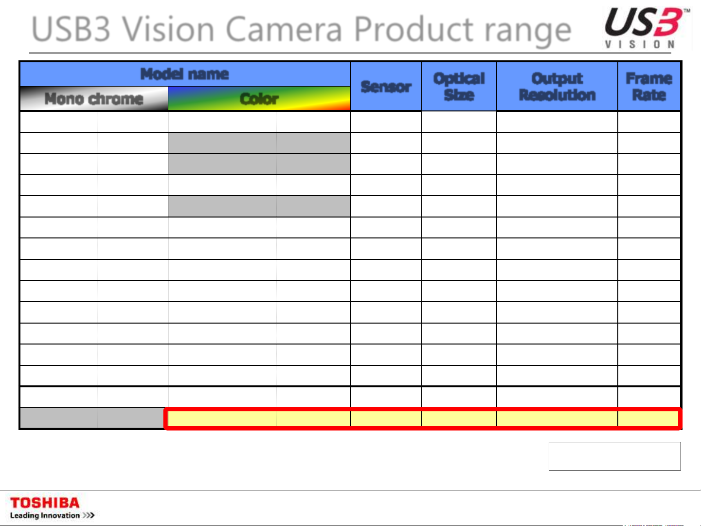
USB3 Vision Camera Product range
Model name
Optical
Output
Frame
Sensor
Mono chrome Color
BU030 Available BU030C/CF Available ICX424A 1/3 inch 640(H) x 480(V) 125fps
BU031 Available ICX414A 1/2 inch 640(H) x 480(V) 125fps
BU080 Available ICX204A 1/3 inch 1,024(H) x 768(V) 40fps
BU130 Available BU130C/CF Available ICX445A 1/3 inch 1,280(H) x 960(V) 30fps
BU132M Q1/2016 EV76C560 1/1.8 inch 1,280(H) x 1,024(V) 60fps
BU205M Available BU205MC/MCF Under study CMV2000 2/3 inch 2,048(H) x 1,088(V) 170fps
BU238M Available
BU302M Q1/2016
BU406M Available
BU505M New
DU657M New DU657MC New Own CMOS 1.1 inch 2,560(H) x 2,560(V) TBD
DU806M In plan
BU238MC/MCF
BU302MC/MCF
BU406MC/MCF
BU505MC/MCF
DU806MC/MCF
Available IMX174 1/1.2 inch 1,920(H) x 1,200(V) 165fps
Q1/2016 IMX252 1/1.8 inch 2,048(H) x 1,536(V) 120fps
Available CMV4000 1 inch 2,048(H) x 2,048(V) 90fps
Q1/2016 IMX250 2/3 inch 2,448(H) x 2,048(V) 75fps
In plan IMX255 1.0 inch TBD TBD
Size
Resolution
Rate
DU1207M In plan
BU602M In plan
Note :
This documents does not confirm product release schedule as information in development plan are included.
Contact our persons in charge of sales for your enquiry.
BU602, BU1203 : Rolling shutter type CMOS sensor
DU1207MC/MCF
BU602MC/MCF
BU1203MC/MCF
In plan IMX253 1.1 inch TBD TBD
In plan IMX178 1/1.8 inch 3,072(H) x 2,048(V) TBD
New IMX226 1/1.7 inch 4,000(H) x 3,000(V) 30fps
Doc. No. 4300-0223
xxxC : without IR cut filter
xxxCF : with IR cut filter
2015/12/25
Dec. 2015
5 Copyright © 2015 TOSHIBA TELI CORPORATION, All rights reserved.
Page 6
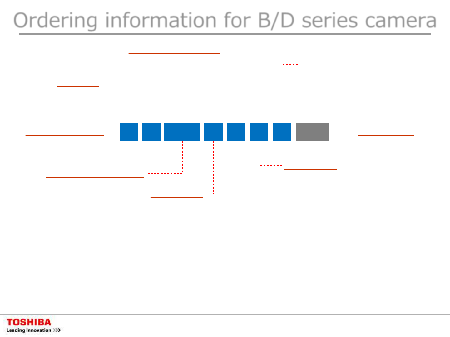
Ordering information for B/D series camera
Image Sensor Type
Interface
U : USB3.0
G : Gigabit Ethernet
C : Camera Link
Model Signature
B : B (Standard) series
D : D (Deluxe) series
Total Pixel Numbers
03 : 0.3 mega pixels
08 : 0.8 mega pixels
13 : 1.3 mega pixels
20 : 2.0 mega pixels
23 : 2.3 mega pixels
30 : 3.0 mega pixels
40 : 4.0 mega pixels
50 : 5.0 mega pixels
60 : 6.0 mega pixels
65 : 6.5 mega pixels
80 : 8.0 mega pixels
120 : 12.0 mega pixels
None : CCD Sensor
M : CMOS Sensor
B U 120 M C F
3
Color Type
None : Black/White(B/W)
C : Color
Image Size
0.3 Mega Pixels Type
0 : 1/3 type
1 : 1/2 type
0.8 Mega Pixels Type
0 : 1/3 type
1.3 Mega Pixels Type
0 : 1/3 type
2 : 1/1.8 type
2.0 Mega Pixels Type
2 : 1/1.8 type
5 : 2/3 type
2.3 Mega Pixels Type
8 : 1/1.2 type
8L : 1/1.2 type, Low-fps
3.0 Mega Pixels Type
2 : 1/1.8 type
2L : 1/1.8 type, Low-fps
4.0 Mega Pixels Type
6 : 1.0 type
Optical Filter Type
None : without IR cut filter
F : with IR cut filter
G : with dust-proof glass
L : with Optical low-pass filter
M : with Opt-LPF + IR cut filter
-CS
5.0 Mega Pixels Type
5 : 2/3 type
5L : 2/3 type, Low-fps
6.0 Mega Pixels Type
2 : 1/1.8 type
6.5 Mega Pixels Type
7 : 1.1 type
8.0 Mega Pixels Type
6 : 1.0 type
12.0 Mega Pixels Type
3 : 1/1.7 type
7 : 1.1 type
Lens Mount
None : C mount
BG205MC(F) only
-CS : CS mount
Rev.1.04
Doc. No. 4300-0223
2015/12/25
6 Copyright © 2015 TOSHIBA TELI CORPORATION, All rights reserved.
Page 7
Advantage of BU1203MC/MCF
Doc. No. 4300-0223
2015/12/25
7 Copyright © 2015 TOSHIBA TELI CORPORATION, All rights reserved.
Page 8
Advantage of BU1203MC/MCF
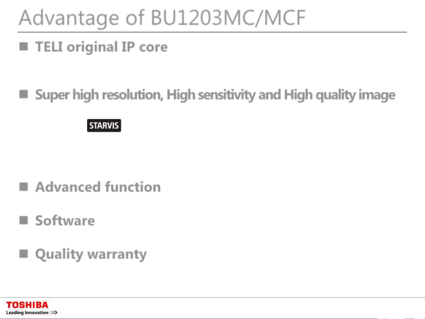
TELI original IP core
High integration, by originally developed innovative technology,
achieves super high speed response
Super high resolution, High sensitivity and High quality image
Adopting Sony’s IMX226(12.4M pixels) RS (Rolling Shutter) CMOS
sensor
Back side irradiation sensor achieves high sensitivity and better
incident angle quality event with its compact pixel size
Less defect and noise with Sony quality
Advanced function
Function with scalable, event notification and image buffer
Software
Free supply of Software developing package “TeliCamSDK”
Quality warranty
Full of 3 years warranty
* STARVIS or STARVIS logo might be trade mark of Sony Corporation.
Doc. No. 4300-0223
2015/12/25
8 Copyright © 2015 TOSHIBA TELI CORPORATION, All rights reserved.
Page 9
Advantage of BU1203MC/MCF
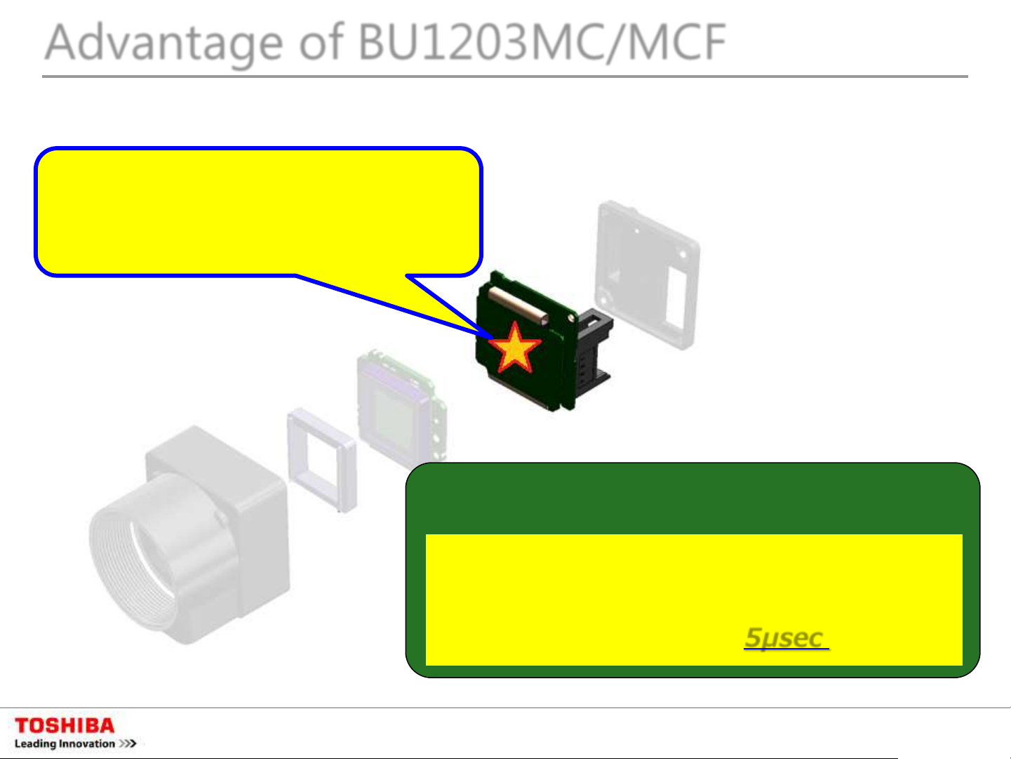
Extremely quick response by original IP
core
Newly developed
TELI original IP core
“TELI IP Core” built in!
<example>
TELI IP Core
response time of software trigger
A company camera: 4msec
BU/DU series: 5μsec (average)
Doc. No. 4300-0223
2015/12/25
9 Copyright © 2015 TOSHIBA TELI CORPORATION, All rights reserved.
Page 10

Advantage of BU1203MC/MCF
Structure difference between surface irradiation type sensor
(conventional) and back side irradiation type sensor
Incident light Incident light
On-chip lens
Color filter
Wiring layer
Light receiving
surface
Photo diode
Incident light is hindered and reduced
by wiring layer before it reaches photo
diode. As a result, sensitivity is reduced.
Surface
irradiation type
Light receiving
surface
Photo diode
Wiring layer
Back-side
irradiation type
Setting photo diode on front surface,
then setting color filter and micro lens
on it. As a result, sensitivity is well kept
without hindrance of wiring layer.
Doc. No. 4300-0223
2015/12/25
10 Copyright © 2015 TOSHIBA TELI CORPORATION, All rights reserved.
Page 11

Specification comparison
Doc. No. 4300-0223
2015/12/25
11 Copyright © 2015 TOSHIBA TELI CORPORATION, All rights reserved.
Page 12

Specification Comparison (sensor)
Pixel Number
Model
Vendor Sony Sony CMOSIS Sony
Type CMOS CMOS CMOS CCD
4,000(H)x3,000(V) /
1.85(H)×1.85(V)μm
Pixel Size
7.40(H)×5.55(V)mm
Diagonal: 9.25mm
Image Size
Optical
Format
IMX226
4,096(H)x2,160(V)
12M / 4K2K
Type 1/1.7
IMX174 CMV2000 ICX274
1,920(H)×1,200(V) 2,048(H)×1,088(V) 1,600(H)×1,200(V)
WUXGA/2.3M 2M UXGA/2M
5.86(H)×5.86(V)μm 5.5(H)×5.5(V)μm 4.4(H)×4.4(V)μm
11.25(H)×7.03(V)mm
Diagonal: 13.27mm
Type 1/1.2 Type 2/3 (1“) Type 1/1.8
11.26(H)×5.98(V)mm
Diagonal: 12.75mm
7.04(H)×5.28(V)mm
Diagonal: 8.80mm
Aspect Ratio
Frame Rate
DR - - - -
SNR - - - -
4:3 / 17:9
34.97fps / 29.97fps
16:10 2:1 4:3
164.5fps 350fps 15fps
Doc. No. 4300-0223
2015/12/25
12 Copyright © 2015 TOSHIBA TELI CORPORATION, All rights reserved.
Page 13
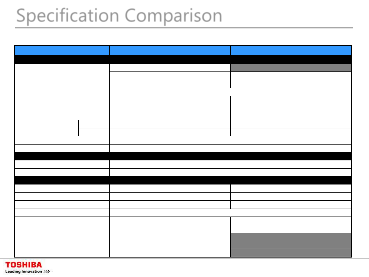
Specification Comparison
【
Color type
Mono
×
Color without IR
Color without IR
Color with IR
Color with IR
Interface
Imaging Element
GS
RS
Electronic shutter type
Global
Rolling
Synchronizing type
Internal or Bus synchronization
Internal
Image data format
Mono
Mono 8
mono 8
Color
Bayer 8
Bayer
Scanning mode
Frame rate
【
Power voltage
Power consumption
【
Shutter type
Global
Rolling Shutter / Global Reset
Shutter speed
*** s
43.28μs ~ 16s
Shutter mode
Normal
Normal
Random trigger
Fixed
○
○
Pulse width mode
○
○
Bulk
○
×
Sequential shutter
○
×
Overlapping trigger
○
×
USB3.0 Camera Specification Comparison by GS/RS (1)
Specification items BU series GS-CMOS type BU1203MC/MCF RS-CMOS type
1. Electric Spec】
USB3.0
30fps
2. Power consumption】
DC5V ± 5%(USB Port)
Subject to sensor specification
3. Electronic shutter】
shutter Hardware / Software
mode
trigger
-cut filter (BU***MC)
-cut filter (BU***MCF)
-CMOS
shutter
Subject to sensor specification
shutter
~ *** s
(MANU) / Random
: Function available
: Function available
: Function available
: Function available
: Function available
: No setting
-cut filter (BU1203MC)
-cut filter (BU1203MCF)
-CMOS
Shutter (Global reset)
8
(Edge mode : 682μs~16s)
(MANU) / Random
: Function available
: Function available
: No function
: No function
: No function
Doc. No. 4300-0223
2015/12/25
13 Copyright © 2015 TOSHIBA TELI CORPORATION, All rights reserved.
Page 14
【
Offset
Gain
MANU
MANU
White balance
MANU / ONCE
MANU /
Gamma correction
LUT
【
All items
【
All items
【
All items
【
All items
【
All items
Specification Comparison
USB3.0 Camera Specification Comparison by GS/RS (2)
Specification items BU series GS-CMOS type BU1203MC/MCF RS-CMOS type
4. Camera function】
5. Mechanical・optical Spec
Common specification
6. Operational environmental conditions
7. Product structure】
Common specification
8. Options】
Common specification
9. Complying Law・regulations】
Common specification
-25 to +25% (Default=0)
0.45 to 1.0
10bit to 10bit
Common specification
ONCE
Doc. No. 4300-0223
2015/12/25
14 Copyright © 2015 TOSHIBA TELI CORPORATION, All rights reserved.
Page 15
Performance Comparison
Doc. No. 4300-0223
2015/12/25
15 Copyright © 2015 TOSHIBA TELI CORPORATION, All rights reserved.
Page 16
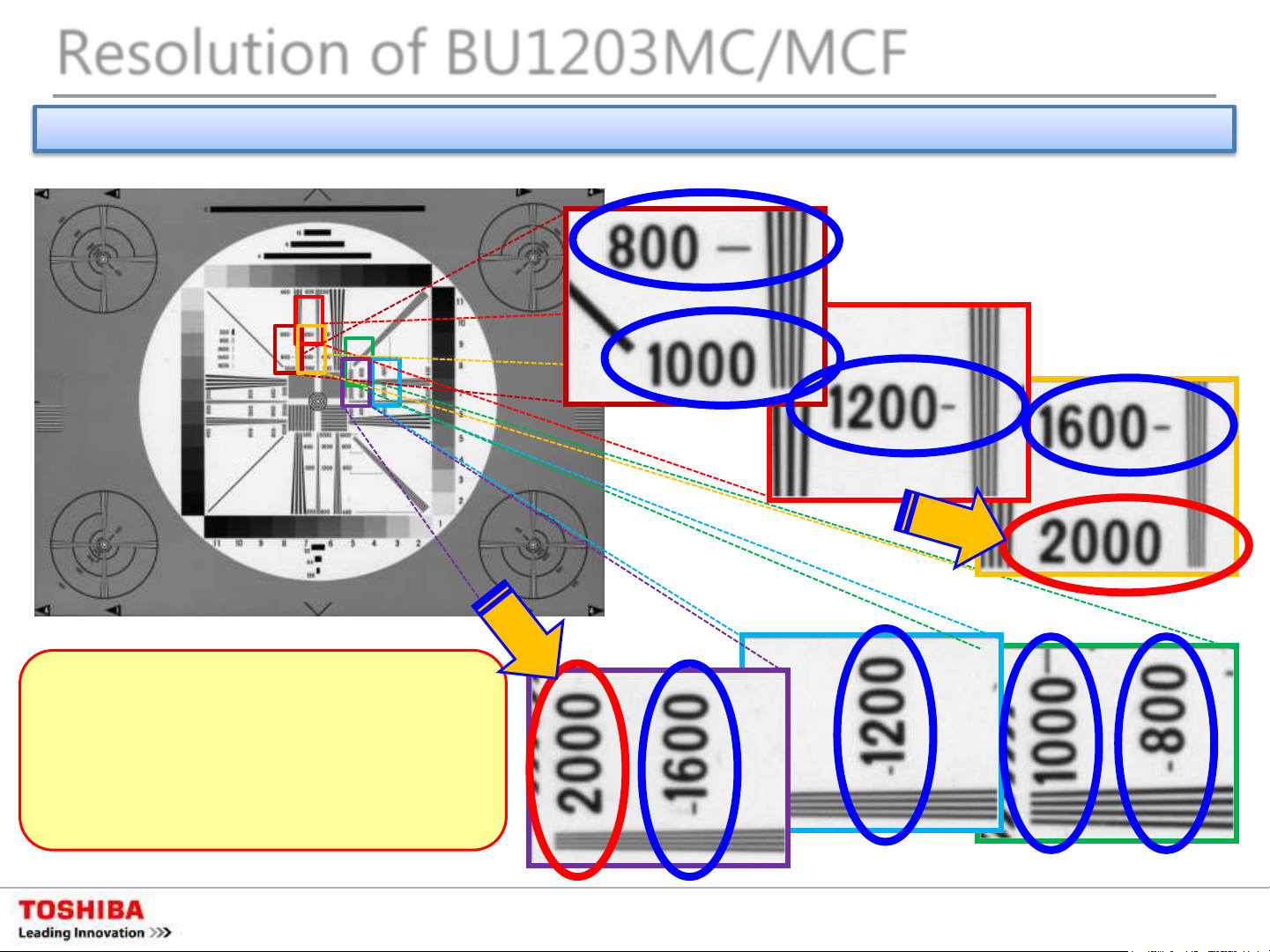
Resolution of BU1203MC/MCF
Example of calculating Bayer output with software equivalent to mono- chrome output
Resolution is 2,000 lines with vertical
4,000 pixels mono chrome sensor. In
case of Bayer color, resolution must
be reduced because of calculation
between pixels. However, tone can be
recognized in 2,000 pixel resolution
Evaluating Lens : KOWA LM25XC (for 4/3 inch)
Doc. No. 4300-0223
2015/12/25
16 Copyright © 2015 TOSHIBA TELI CORPORATION, All rights reserved.
Page 17

Resolution comparison
Resolution comparison of BU1203MCF(12Mpix) & BU406MCF(4Mpix)
Comparing images of the same work size by BU1203MCF and BU406MCF camera with 4MCMOS, apparently image by BU1208MCF has higher resolution due to its 2 times resolution
And, image by BU1203 does not obviously show color false peculiar to single sensor camera.
Doc. No. 4300-0223
2015/12/25
17 Copyright © 2015 TOSHIBA TELI CORPORATION, All rights reserved.
Page 18

Example of resolution difference by lens
<Resolution Chart>
25mm lens
for video camera
With lens for image sensor more than 1 inch, image is clear up to about
25mm lens
for 4/3 inch
2,000 line pairs resolution. Even with video camera lens which is not for
mega pixel, resolution in about 1,000 to 1,600 line pairs can be achieved.
Doc. No. 4300-0223
2015/12/25
18 Copyright © 2015 TOSHIBA TELI CORPORATION, All rights reserved.
Page 19

Advanced Function
Doc. No. 4300-0223
2015/12/25
19 Copyright © 2015 TOSHIBA TELI CORPORATION, All rights reserved.
Page 20

Advanced Function (“MONO” output mode)
MONO output mode from color camera
Color camera generally output signal in RGB or RAW (Bayer). This function is to
get output like mono chrome camera by calculating brightness from RGB.
① Conversion from Bayer to RGB (example)
Among single plate color sensors,
primary color RGB type sensor
proceed through zigzag
alignment (Bayer array) as chart
shown in left.
A screen of RGB color can be
output by interpolation on each
RGB element
Left chart shows typical
assignment method among
various interpolation method.
Bayer array
RGB output RGB pixel interpolation
Such as enhancing image quality
by neighbor pixel calculation
after RGB conversion, and
interpolation by calculation with
dynamic switching on detected
brightness in horizontal and
vertical.
Doc. No. 4300-0223
2015/12/25
20 Copyright © 2015 TOSHIBA TELI CORPORATION, All rights reserved.
Page 21

Advanced Function (“MONO” output mode)
② RGB to Y Conversion
Calculating brightness (Y) with RGB signal converted from Bayer signal, this
camera outputs mono chrome signal as mono chrome camera.
Brightness signal (Y) and
chrominance signal (U/V) can be
calculated from RGB signal.
General formulas are ;
Y=0.30R+0.59G+0.11B
U=-0.17R-0.33G+0.50B
V=0.50R-0.42G-0.08B
RGB signal YUV(YCbCr) signal
⇩
Output Y signal among above as
mono chrome signal from
camera.
Might be Cb/Cr or Pb/Pr depend
on calculation coefficient.
Doc. No. 4300-0223
2015/12/25
21 Copyright © 2015 TOSHIBA TELI CORPORATION, All rights reserved.
Page 22

Advanced Function
Event notice function :
Camera status can be referred through USB3 by using event packet of USB3 Vision
(1) Frame Trigger : Reception of Frame Start Trigger
(2) Frame Trigger Error : Rejection of Frame Start Trigger
(3) Frame Trigger Wait : Start of waiting for Frame Start Trigger
(4) Frame Transfer Start : Start of transferring Streaming data
(5) Frame Transfer End : End of Transferring Streaming data
(6) Exposure Start : Start of Exposure
(7) Exposure End : End of Exposure
Doc. No. 4300-0223
2015/12/25
22 Copyright © 2015 TOSHIBA TELI CORPORATION, All rights reserved.
Page 23

Advanced Function
Image buffer :
As BU(CMOS) series have 64MB image buffer memory in it, recorded image data
can be read from host PC at any time.
Frames can be recorded and read
Correction function of pixel defect :
BU(CMOS) series have correction function of pixel defect. This function can be
switched on and off depend on occasion.
Corrected
Doc. No. 4300-0223
2015/12/25
23 Copyright © 2015 TOSHIBA TELI CORPORATION, All rights reserved.
Page 24

Documents
Doc. No. 4300-0223
2015/12/25
24 Copyright © 2015 TOSHIBA TELI CORPORATION, All rights reserved.
Page 25

Reference Documents
• Specification sheet
(for BU1203MC/MCF)
• Instruction manual
(for BU1203MC/MCF)
These documents are available in our HP to download;
http://www.toshiba-teli.co.jp/en/products/industrial/
Doc. No. 4300-0223
2015/12/25
25 Copyright © 2015 TOSHIBA TELI CORPORATION, All rights reserved.
Page 26

[Appendix]
Explanation of Shutter function
Doc. No. 4300-0223
2015/12/25
26 Copyright © 2015 TOSHIBA TELI CORPORATION, All rights reserved.
Page 27

Basic of electronic shutter (shutter, reset)
Shutter mode
Assigning exposure time to sensor
Global shutter;
Shutter mode which takes image by exposure for all pixels (1 frame) in one time
Applied to CCD sensor and some of CMOS sensor
Stable imaging for Motion picture and still picture
Rolling shutter;
Shutter mode which has different exposure timing on each line. Most of CMOS sensors are
applied.
Digital camera, mobile phone, smart phone, web camera, low cost monitor camera, mobile
camera etc.
Disadvantage of distortive image in motion picture
Reset mode
Action of clearing the information
(charge, electron) in sensor before
taking fresh image
Global reset;
A mode of reset which reset all pixels in one time
Rolling reset;
This resets on each line.
Sensor operation :
reset➡exposure➡
reset➡exposure➡・・・
Repeating above
Doc. No. 4300-0223
2015/12/25
27 Copyright © 2015 TOSHIBA TELI CORPORATION, All rights reserved.
Page 28

Basic of electronic shutter (combination of shutter and reset)
1. Global shutter + global reset
Complete global shutter action
As scanning time is longer in lower part of image, black floating phenomenon
might be caused by dark current effect. =This can be corrected as it is slight
2. Global shutter + rolling reset
Global shutter mode can reduce an effect of time difference during reading by
resetting on each line
In some cases, effect of virtual global reset is achieved by high speed rolling
reset
3. Rolling shutter + global reset
As only resetting is done in one time, exposure time after reset varies on each
line.
=The lower part of image is the brighter as exposure time is longer.
4. Rolling shutter + rolling reset
Complete Rolling shutter action
Stable exposure process as both reset and shutter are rolling mode
Easier to make low noise type sensor as structure of less pixel transistor number.
As disadvantage, motion image shot under continuous light will be distortive.
Doc. No. 4300-0223
2015/12/25
28 Copyright © 2015 TOSHIBA TELI CORPORATION, All rights reserved.
Page 29

Image comparison by shutter mode
Output comparison of rotating subject
Global shutter
Output image of moving
subject is distortive
Rolling shutter
Complete image of moving
subject
Doc. No. 4300-0223
2015/12/25
29 Copyright © 2015 TOSHIBA TELI CORPORATION, All rights reserved.
Page 30

Shutter mode comparison 1
CMOSIS_4M
Same exposure start time in each line. Hence no distortion
GS: Global shutter
of moving subject image under constant light.
Trigger input
Data reading
1st line: exposure
2nd line: exposure
3rd line: exposure
・ ・ ・
Resetting all the
lines at the same
time.
Start exposure
Exposure time is same in each line
各ラインごとに
Last line: exposure
露光開始タイミングが異なる。
Aptina_5M
RS: Rolling shutter
Trigger input
Data reading
1st line: exposure
2nd line: exposure
・
・
・
1 2 3 ・ ・ ・ ・
1
2
3
・ ・ ・ ・
・ ・ ・ ・
Output image
Moving direction
Exposure start time is different in each line. Hence
“distortion” of moving subject image is caused under
constant light.
・
・
・
1 2 3 ・ ・ ・ ・
1
2
3
・ ・ ・ ・
・ ・ ・ ・
Output image
No
distortion
distortion!
Resetting and
starting exposure
in each line.
3rd line: exposure
Exposure starting
time is different
in each line.
Exposure time length is same in all the line
Last line: exposure
Doc. No. 4300-0223
Moving direction
2015/12/25
30 Copyright © 2015 TOSHIBA TELI CORPORATION, All rights reserved.
Page 31

Shutter mode comparison 2
* data here are based on comparison test in our
company. It may vary subject to circumstances.
Global shutter
still
Constant
light
moving
Constant
light
Rolling shutter
Constant light
Constant
light
Constant light
Strobe
needed
Global reset
Strobe
needed
Strobe
needed
Moving direction Moving direction Moving direction
Doc. No. 4300-0223
2015/12/25
31 Copyright © 2015 TOSHIBA TELI CORPORATION, All rights reserved.
Page 32

Image depend on moving direction of subject
Changing moving direction of subject in rolling shutter mode
Moving left Moving up
moving
moving
Changing camera angle against subject, distortion of image changes.
In case of shooting subject in moving vertically with constant speed,
image data without distortion can be gained by compensating
constant enhancement in vertical.
(* verification by actual camera is necessary. In case of global reset, problem might be caused as lower lins have fainting.)
Doc. No. 4300-0223
2015/12/25
* Image
32 Copyright © 2015 TOSHIBA TELI CORPORATION, All rights reserved.
Page 33

Shutter mode comparison 3
Aptina_5M
Global reset
(rolling shutter+global reset)
Trigger input
Data reading
Resetting and
starting exposure
in all the lines at
the same time
As no difference in exposure starting time in lines like rolling
shutter, exposure starting time can be measured easily as
global shutter.
Starting time of exposure is same in each line. However, exposure
time length are longer in lower line. Hence distortion and
luminance difference in image is caused under constant light.
・
・
・
・
1st line: exposure
2nd line: exposure
3rd line: exposure
各ラインごとに
露光開始タイミングが異なる。
Exposure time length is different in each line
・ ・ ・
Last line: exposure
1 2 3 ・ ・ ・ ・
1
・
2
3
・ ・ ・ ・
・ ・ ・ ・
Output image
However, as exposure ending time is different in each line,
image of moving subject under constant light is distortive due
to luminance difference.
As a result, low cost advantage will be offset by additional cost
of strobe. There is a certain advantage of easier measurement
in exposure starting time comparing with rolling shutter.
Doc. No. 4300-0223
2015/12/25
33 Copyright © 2015 TOSHIBA TELI CORPORATION, All rights reserved.
Page 34

vs. Global reset
* data here are based on comparison test in our
company. It may vary subject to circumstances.
Camera output comparison in shooting even luminance subject
under constant light
Global shutter
Rolling shutter
Under constant light, both of global shutter and rolling shutter can be
Global reset
(Rolling shutter+Global reset)
used for shooting.
In case of global reset, the lower part becomes brighter due to duration
time of output and exposure time.
⇒ Proper light (strobe) is necessary
Doc. No. 4300-0223
2015/12/25
34 Copyright © 2015 TOSHIBA TELI CORPORATION, All rights reserved.
Page 35

Basic timing of rolling shutter 1
① Shooting with constant light
External light
Output frame
・
・
Output data
・
・
・
・
・
・
・
・
・
・
Exposure
in sensor
1st line : exposure
2nd line : exposure
3rd line : exposure
1st line : exposure
2nd line : exposure
3rd line : exposure
Can shoot without any problem
1st line : exposure
under constant exposure
condition.
2nd line : exposure
3rd line : exposure
th
N
line : exposure
th
N
line : exposure
th
N
line : exposure
② Shooting in random trigger mode with strobe (no overlap)
Strobe
Output frame
Exposure
in sensor
1st line : exposure
2nd line : exposure
3rd line : exposure
・
・
・
With strobe emission timing, exposure
starts from 1st line, exposure time
・
・
・
becomes shorter in 2nd line and
1st line : exposure
after. No exposure in some lines.
2nd line : exosure
3rd line : exposure
Nth line : exposure
nライン目: 露光
* verification under actual condition is necessary
Doc. No. 4300-0223
2015/12/25
35 Copyright © 2015 TOSHIBA TELI CORPORATION, All rights reserved.
Page 36

Basic timing of rolling shutter 2
③ Shooting in constant interval with strobe (no overlap)
Strobe
Output frame
・
・
・
・
Output data
・
1st line : exposure
2nd line : exposure
Exposure
in sensor
3rd line : exposure
Nth line : exposure
④ Shooting in constant interval with strobe (with overlap)
Strobe
Output frame
・
・
Output data
Exposure
in sensor
・
1st line : exposure
2nd line : exposure
3rd line : exposure
・
1st line : exposure
2nd line : exposure
3rd line : exposure
・
・
・
1st line : exposure
2nd line : exposure
3rd line : exposure
・
・
・
In the way of synchronizing strobe
emission to output frame signal,
subject can be shot without
problem under no overlap
1st line : exposure
2nd line : exposure
3rd line : exposure
exposure condition.
Nth line : exposure
Nth line : exposure
Some lines start exposure for
another frame in the same
・
・
・
exposure time. Double image is
caused because next frame
1st line : exposure
exposure starts in same
2nd line : exposure
output frame.
3rd line : exposure
・
・
・
・
・
・
Nth line : exposure
Nth line : exposure
Doc. No. 4300-0223
Nth line : exposure
* verification under actual condition is necessary
2015/12/25
36 Copyright © 2015 TOSHIBA TELI CORPORATION, All rights reserved.
Page 37

Basic timing of global reset 1
⑤ Shooting with constant light at random trigger (no overlap)
External light
External
trigger
Output frame
・
・
・
The lower in screen, the brighter
as longer exposure
・
・
・
Exposure
in sensor
1st line : exposure
2nd line : exposure
3rd line : exposure
1st line : exposure
2nd line : exposure
3rd line : exposure
Nth line : exposure
Nth line : exposure
⑥ Shooting with strobe at random trigger (no overlap)
Strobe
Output frame
・
・
Exposure
in sensor
1st line : exposure
2nd line : exposure
3rd line : exposure
・
Exposure of all lines starts when
1st line : exposure
trigger is input, and exposure of all lines
2nd line : exposure
complete before image output.
Hence no problem for shooting.
3rd line : exposure
・
・
・
Nth line : exposure
Nth line : exposure
* verification under actual condition is necessary
Doc. No. 4300-0223
2015/12/25
37 Copyright © 2015 TOSHIBA TELI CORPORATION, All rights reserved.
Page 38

Basic timing of global reset 2
⑦ Shooting in constant interval with strobe (no overlap)
Strobe
Output frame
Output data
Exposure
in sensor
・
・
・
・
・
1st line : exposure
2nd line : exposure
3rd line : exposure
・
1st line : exposure
Subject can be shot without problem
2nd line : exposure
as exposure starting point is aligned
by global reset and shutter time
3rd line : exposure
is decided by strobe light.
Nth line : exposure
Nth line : exposure
⑧ Shooting in constant interval (with overlap)
Strobe
Output frame
Output data
Exposure
in sensor
・
・
・
・
・
1st line : exposure
2nd line : exposure
・
3rd line : exposure
Exposure of all line starts in strobe
emission timing. However, exposure time
becomes shorter from starting
1st line : exposure
line to midway line.
2nd line : exposure
3rd line : exposure
・
・
・
1st line : exposure
2nd line : exposure
・
・
・
3rd line : exposure
Nth line : exposure
・
・
・
1st line : exposure
2nd line : exposure
・
・
・
3rd line : exposure
Nth line : exposure
Nth line : exposure
Doc. No. 4300-0223
Nth line : exposure
* verification under actual condition is necessary
2015/12/25
38 Copyright © 2015 TOSHIBA TELI CORPORATION, All rights reserved.
Page 39

Summary of shutter action ~ still image
Shooting still subject with constant light
Shutter mode
Global shutter
(global shutter + global reset)
Rolling shutter
(rolling shutter + rolling reset)
Global reset
(rolling shutter + global reset)
Shutter OFF
Synchro in Camera,
with overlap
◎ ◎ ◎
①
◎ ◎
✕
⑤
V shading
Shutter ON
Synchro in camera,
without overlap
①
✕
V shading
Random trigger
No overlap With overlap
(◎) -
✕
V shading
Shooting still subject with synchronized strobe
Shutter mode
Shutter OFF
Synchro in camera,
with overlap
Shutter ON
Synchro. In camera,
without overlap
Random trigger
No overlap With overlap
* verification in actual
condition is necessary
○
Might be shutter scratch
(✕)
V shading
Global shutter
(global shutter + global reset)
Rolling shutter
(rolling shutter + rolling reset)
Global reset
(rolling shutter + global reset)
◎
Almost nil in this case
✕
④
Double exposure
✕
V shading
◎ ◎
◎
③
◎ ◎
⑦
Non exposure line
(✕)
⑥
Doc. No. 4300-0223
②
○
Probably shutter
-
(✕)
V shading
* BU1203MCF
2015/12/25
⑧ ⑤
39 Copyright © 2015 TOSHIBA TELI CORPORATION, All rights reserved.
Page 40

Summary of shutter action ~motion image
Shooting motion image with constant light
Shutter mode
Shutter OFF
Synchro. In camera,
with overlap
Shutter ON
Synchro. In camera,
no overlap
Random trigger
No overlap With overlap
* verification in actual
condition is necessary
Global shutter
(global shutter + global reset)
Rolling shutter
(rolling shutter + rolling reset)
Global reset
(rolling shutter + global reset)
V shading, distortion, fading
◎ ◎ ◎
△
distortion
✕
V shading, distortion, fading
△
distortion
✕
distortion
V shading, distortion, fading
Might be shutter scratch
△
distortion
✕
V shading, distortion, fading
Shooting motion image with synchronized strobe
Shutter mode
Shutter OFF
Synchro. In camera,
with overlap
Shutter ON
Synchro. In camera,
no overlap
Random trigger
No overlap With overlap
○
△
✕
Global shutter
(global shutter + global reset)
Rolling shutter
(rolling shutter + rolling reset)
Global reset
(rolling shutter + global reset)
◎ ◎ ◎
✕
Double exposure
✕
Unexposed line
△
distortion
◎ ◎
✕
Unexposed line
Doc. No. 4300-0223
○
Might be shutter scratch
✕
Double exposure
✕
Unexposed line
* BU1203MCF
2015/12/25
40 Copyright © 2015 TOSHIBA TELI CORPORATION, All rights reserved.
Page 41

[Appendix]
Introduction of USB3.0/USB3 Vision
Doc. No. 4300-0223
2015/12/25
41 Copyright © 2015 TOSHIBA TELI CORPORATION, All rights reserved.
Page 42

About USB3.0
Back ground of USB3.0
USB was started to be used for PC peripherals such as mouse, keyboard, printer etc.
in its early stage. And USB2.0 became majority which can be connected to mass
storage like HDD.
Gradually, USB is also used for sequential data transfer such as audio and video.
As internet is getting more popular, USB3.0 became an interface which can handle
more data. Official support to USB3.0 by Windows 8 also helps its popularity.
Output data from camera is getting larger with higher speed than before in
accordance with transition of CCD to CMOS sensor in it.
USB3.0 is adopted as an interface which can handle these data. USB3.0 is expected
as an interface for worldwide use by standardization of protocol as “USB3 Vision”.
Industrial cameras with USB3.0 get ready to spread in the market with USB’s
advantage of board less use and various availability of PC peripherals.
Transition of USB standard
USB has been quite popular as
multipurpose PC interface for about
20 years since USB1.0 in 1996.
USB3.1 standard will start following
the tremendous performance
improvement of USB3.0.
Standard USB1.0 USB2.0 USB3.0
Year 1996 2000 2008
Data rete 12Mbps 480Mbps 5Gbps
Max.
current
Doc. No. 4300-0223
500mA 900mA
2015/12/25
42 Copyright © 2015 TOSHIBA TELI CORPORATION, All rights reserved.
Page 43

USB3.0 interface(outline)
■Bit rate : max. 5Gbps (Super Speed)
1
2
3
4
Can transfer Uncompressed HDTV (1920x1080) image in 60fps
■Cable length : No limit in standard (actual 5m)
Length will be extended with cable quality and
compensation device improvement
Over 20m transfer by active optical cable (AOC)
8m is available
with combination
■Number of axis : 9 lines
4 lines : USB2.0 signal
4 lines : for expanded super speed signal
1 line :GND
■Communication mode : Full duplex
Improved in communication efficiency against USB2.0 (half duplex)
■Bus power source : max. 900mA
of system.
5
6
Up to 4.5W with 5V supply
Image transfer of our USB3.0
camera is supported by
USB3.0 standard
■Lower compatibility
USB3.0 device can be connected to USB2.0 port (works as USB2.0 )
USB2.0 device can be connected to USB3.0 port
Doc. No. 4300-0223
2015/12/25
43 Copyright © 2015 TOSHIBA TELI CORPORATION, All rights reserved.
Page 44

Physical spec. of USB standard (reference)
USB2.0
Connector types
Pin array of standard USB connector
Function(Host side) Function(Device side)
Pin array of mini-microUSB connector
Function(Host side) Function(Device side)
Connector types
BU/DU series
Standard -A
Standard -B
USB3.0
Signal for USB3.0
Signal for USB2.0
USB2.0 : Black
USB3.0 : Blue
MICRO-B
Micro socket for USB3.0
added connector with USB3.0 standard is
arrayed beside USB2.0 micro connector.
No.1 : Power resource (VBUS)
No.2 : USB2.0 Differential pair (D-)
No.3 : USB2.0 Differential pair (D+)
No.4 : USB OTG ID
No.5 : GND
No.6 : USB3.0 Signal sending line (-)
No.7 : USB3.0 Signal sending line (+)
No.8 :
No.9 : USB3.0 Signal receiving line (-)
No.10 : USB3.0 Signal receiving line (+)
Doc. No. 4300-0223
2015/12/25
44 Copyright © 2015 TOSHIBA TELI CORPORATION, All rights reserved.
Page 45

What’s USB3 Vision?
Machine vision standard
(IEEE1394 by IIDC, Gig-E by Gig-E Vision )
High band width of 5Gbps (440 MByte/s)
Easy connection with Plug & Play
Standardized software interface with GenICam
Much improved robust than USB2.0
Doc. No. 4300-0223
2015/12/25
TM
45 Copyright © 2015 TOSHIBA TELI CORPORATION, All rights reserved.
Page 46

Comparison of major industrial interface
Speed (band
width)
Unification of
procedures
Multiple cameras
Simultaneous
transfer
Bus power
supply
Easiness (non
expert)
CPU load Low Slightly high Very low Very low Very low
USB3.0
Ethernet
<4Gbps
5Gbps の80%)
(
USB3 Vision
(GenICam/IIDC)
○
◎
Standard PoE limited Standard PoCL limited Standard
◎
<1Gbps 655Mbps
GigEVision
(GenICam)
◎ ◎
○
○
Gigabit
IEEE1394
(S800)
IIDC No standard
◎
◎
Camera
Link
2.04Gbps
(Base Configuration)
On FGB On FGB
On FGB On FGB
△ △
CoaXPress
5Gbps
(6.125Gbpsの80%)
GenICam/
IIDC2
Connector size
Connector
reliability
Maximum cable
length
◎ ◎
○ ○
5m
(no limit in
standard)
<100m
○ △
◎ ◎ ◎
4.5m
(no limit in
standard)
(at first)
<10m <100m
Doc. No. 4300-0223
◎
2015/12/25
46 Copyright © 2015 TOSHIBA TELI CORPORATION, All rights reserved.
Page 47

High bandwidth transfer
• Taking advantage of high speed image sensor
HIGH
Bandwidth
Sensor : Sony IMX174
Resolution : 1920 x 1200 (2.3MP)
GigEVision Camera
Max. frame rate 50fps
Data rate 115MB/s
sensor : CMOSIS CMV4000
resolution : 2048 x 2048 (4.2MP)
…USB3.0
• High bandwidth transfer by burst transfer
…USB3.0
USB3 Vision Camera
Max. frame rate 165fps
Data rate 380MB/s
GigEVision Camera
Max. frame rate 25fps
Data rate 105MB/s
USB3 Vision Camera
Max. frame rate 90fps
Data rate 377MB/s
Doc. No. 4300-0223
2015/12/25
47 Copyright © 2015 TOSHIBA TELI CORPORATION, All rights reserved.
Page 48

Burst transfer compliancy
■USB2.0 : non compliancy to burst transfer
USB2.0 packet sequence cannot use bus band efficiently
Host PC
Camera
IN
DATA
ACK
IN
ACK
DATA
■USB3.0 : compliancy to burst transfer
bus band can be used efficiently with burst transfer of USB3.0
Host PC
camera
ACK
DATA
ACK
DATA DATA
ACK
ACK
DATA
ACK
ATA
ACK
time
time
Doc. No. 4300-0223
2015/12/25
48 Copyright © 2015 TOSHIBA TELI CORPORATION, All rights reserved.
Page 49

Comparison of system cost
LOW
COST
Frame Grabber Low Low Medium High
Cable Low Low Medium High
Power Supply Bus
Camera Low Medium Medium Low
• Accessories with reasonable price…USB3.0
• No need of external power source…USB3.0
Camera
USB3.0 GigE 1394.b
Link
External
Bus
/ PoE
External
/ PoCL
4 Camera System Cost
Low Medium Medium High
Doc. No. 4300-0223
2015/12/25
49 Copyright © 2015 TOSHIBA TELI CORPORATION, All rights reserved.
Page 50

Applicable range of USB3.0
CameraLink
Medium Configuration
USB3.0
(4Gbps)
(4Gbps)
CSC6M100BMP11 DU657M
A camera (CL-FullConfig)
About JPY420k
A camera (USB3 Vision)
About JPY276k
camera (6.5M) : JPY280k
board : JPY100k
cable : JPY30k
camera (6.5M): JPY260k
board : JPY8k
cable : JPY8k
(power) : JPY10k
Big cost down by replacing Camera Link system with USB3.0 system!
Doc. No. 4300-0223
2015/12/25
50 Copyright © 2015 TOSHIBA TELI CORPORATION, All rights reserved.
Page 51

High reliability
• Reliable data transfer is ensured …USB3.0
HIGH
• Packet format, Appropriate for DMA transfer
Reliability
…USB3 Vision
Protocol Layer
data check by CRC
packet retransmission in protocol layer level
Error protection of USB3.0 is
Link Layer
much improved from USB2.0
data check by CRC
packet retransmission in protocol layer level
Physical Layer
bit error ratio in physical layer level is less than 1x10
Doc. No. 4300-0223
-12
bits
2015/12/25
51 Copyright © 2015 TOSHIBA TELI CORPORATION, All rights reserved.
Page 52

USB3 Vision packet format
■UVC (USB Video Class) packet format
CPU analyzes header, and separate it from image data.
Over head is bigger, CPU process and communication becomes unstable.
header Image data
■USB3 Vision packet format
time
CPU processing and communication is stable because of less CPU load as
image data is deployed on memory at one time by DMA transfer.
time
header Image data
Trailer
Doc. No. 4300-0223
2015/12/25
52 Copyright © 2015 TOSHIBA TELI CORPORATION, All rights reserved.
Page 53

Doc. No. 4300-0223
53 Copyright © 2015 TOSHIBA TELI CORPORATION, All rights reserved.
 Loading...