

Page 1
TEC Ink Jet Printer
Table of Contents
BRST-10 SERIES
Owner’s Manual
Page 2
DECLARATION OF CONFORMITY (for EU only)
Manufacturer : TOSHIBA TEC CORPORATION
Address : 570 Ohito, Ohito-cho, Tagata-gun, Shizuoka-ken, Japan
declares, it sole responsibility, that the product
Product Name : Remote Printer
Model Number : BRST-10
conforms to the following standards under EMC Directive (89/336/EEC, 93/68/EEC) and
Low Voltage Directive (73/23/EEC, 93/68/EEC) :
EMC : EN55024 Information technology equipment - Immunity characteristics -
Limits and method of measurement
: EN55022 Limits and methods of measurement of radio disturbance
characteristics of information technology equipment
LVD : EN60950 Safety of imformation technology equipment, including
electrical business equipment
WARNING
This is a Class A product. In a domestic environment this product may cause radio interference in which
case the user may be required to take adequate measures.
ATTENTION
Ce produit est de classe A. Dans un environnement domestique, il peut causer des interférences radio.
Auquel cas, I’utilisateur sera amené à prendre les mesures adéquates.
Warnung
Dies ist ein Klasse A Produkt. In einer örtlichen Umgebung kann dieses Gerät Funkstörungen verursachen.
Atención
Este es un producto de la clase A. En ambientes domésticos éste producto puede causar radio
interferencias en cuyo caso el usuario deberá tomar las medldas oportunas.
VERWITTIGING
Dit is een klasse A produkt. Het gebruik hiervan kan radio interferenties veroorzaken die de gebruiker
ertoe kunnen dwingen sommige maatregelen te moeten treffen.
Schallemission : unter 70dB(A) nach DIN 45635 (ISO7779)
FCC Notice
This equipment has been tested and found to comply with the limits for a Class A digital device, pursuant
to Part 15 of the FCC Rules. These limits are designed to provide reasonable protection against harmful
interference when the equipment is operated in a commercial environment. This equipment generates,
uses, and can radiate radio frequency energy and, if not installed and used in accordance with the
instruction manual, may cause harmful interference to radio communications. Operation of this equipment
in a residential area is likely to cause harmful interference in which case the user will be required to
correct the interference at this own expense.
Changes or modifications not expressly approved by the manufacturer for compliance could void the
user’s authority to operate the equipment.
Copyright © 2000
by TOSHIBA TEC CORPORATION
All Rights Reserved
570 Ohito, Ohito-cho, Tagata-gun, Shizuoka-ken, JAPAN
Page 3
Safety Summary
Safety Summary
Personal safety in handling or maintaining the equipment is extremely important. Warnings and Cautions
necessary for safe handling are included in this manual. All warnings and cautions contained in this
manual should be read and understood before handling or maintaining the equipment.
Do not attempt to effect repairs or modifications to this equipment. If a fault occurs that cannot be rectified
using the procedures described in this manual, turn off the power, unplug the machine, then contact your
authorized TOSHIBA TEC representative for assistance.
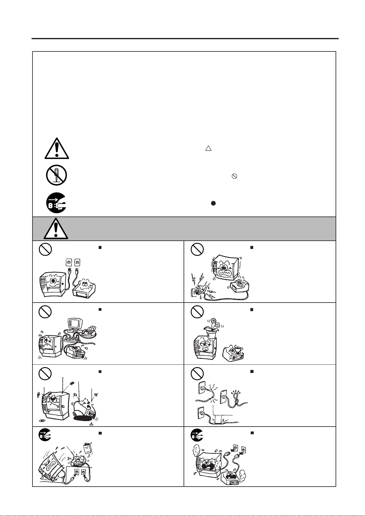
Meaning of Each Symbol
This symbol indicates warning items (including cautions).
Specific warning contents are drawn inside the symbol.
(The symbol on the left indicates a general caution.)
This symbol indicates prohibited actions (prohibited items).
Specific prohibited contents are drawn inside or near the symbol.
(The symbol on the left indicates “no disassembling”.)
This symbol indicates actions which must be performed.
Specific instructions are drawn inside or near the symbol.
(The symbol on the left indicates “disconnect the power cord plug from the outlet”.)
EO1-13013
WARNING
Any other than the
specified AC voltage
is prohibited.
Prohibited
Prohibited
Do not use voltages other than the
voltage (AC) specified on the rating
plate, as this may cause fire or
electric shock.
If the machines share the same
outlet with any other electrical
appliances which consume large
amounts of power, the voltage will
fluctuate widely each time these
appliances operate each time these
appliances operate, and this may
cuase the machines to malfuncion. Be
sure to provide au exclusive outlet for
the machines.
Do not insert or drop metal,
flammable or other foreign objects into
the machines through the ventilation
slits, as this may cause fire or electric
shock.
This indicates that there is the risk of death or serious injury if the
machines are improperly handled contrary to this indication.
Prohibited
Prohibited
Prohibited
Do not plug in or unplug the power
cord plug with wet hands as this may
cause electric shock.
Do not place metal objects or
water-filled containers such as flower
vases, flower pots or mugs, etc. on
top of the machines. If metal objects
or spilled liquid enter the machines,
this may cause fire or electric
shock.
Do not scratch, damage or modify
the power cords. Also, do not place
heavy objects on, pull on, or excessively bend the cords, as this may
cause fire or electric shock.
Disconnect
the plug.
If the machines are dropped or their
cabinets damaged, first turn off the
power switches and disconnect the
power cord plugs from the outlet, and
then contact your authorized
TOSHIBA TEC representative for
assistance. Continued use of the
machine in that condition may cause
fire or electric shock.
(i)
Disconnect
the plug.
Continued use of the machines in an
abnormal condition such as when the
machines are producing smoke or
strange smells may cause fire or elec-
tric shock. In these cases, immediately turn off the power switches and
disconnect the power cord plugs from
the outlet. Then, contact your authorized TOSHIBA TEC representative for
assistance.
Page 4
Safety Summary
EO1-13013
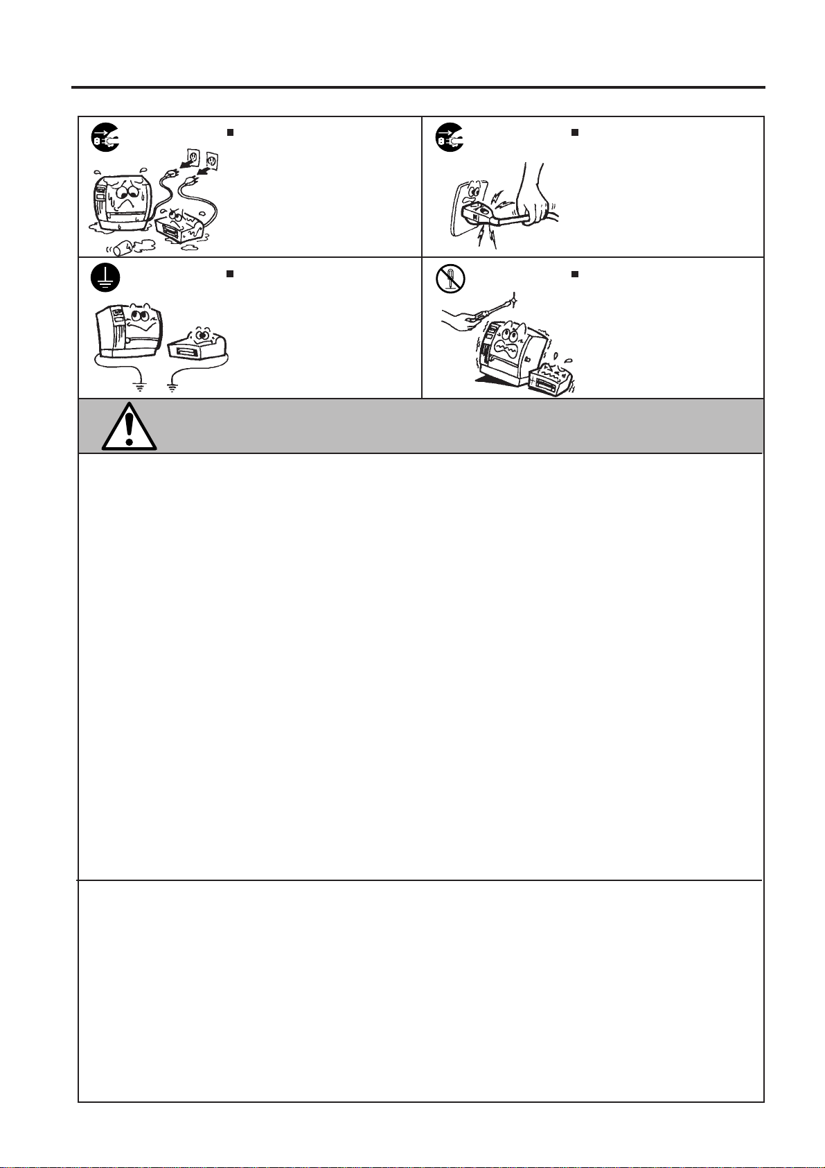
Disconnect
the plug.
Connect a
grounding
wire.
If foreign objects (metal fragments,
water, liquids) enter the machines,
first turn off the power switches and
disconnect the power cord plugs from
the outlet, and then contact your
authorized TOSHIBA TEC representative for assistance. Continued
use of the machine in that condition
may cause fire or electric shock.
Ensure that the equipment is
properly grounded. Extension cables
should also be grounded. Fire or
electric shock could occur on
improperly grounded equipment.
Disconnect
the plug.
No disassembling.
When unplugging the power cords,
be sure to hold and pull on the plug
portion. Pulling on the cord portion
may cut or expose the internal wires
and cause fire or electric shock.
Do not remove covers, repair or
modify the machine by yourself. You
may be injured by high voltage, very
hot parts or sharp edges inside the
machine.
This indicates that there is the risk of personal Injury or damage to
CAUTION
objects if the machines are improperly handled contrary to this indication.
Precautions
The following precautions will help to ensure that this machine will continue to function correctly.
• Try to avoid locations that have the following adverse conditions:
* Temperatures out of the specification * Direct sunlight * High humidity
* Shared power source * Excessive vibration * Dust/Gas
• The cover should be cleaned by wiping with a dry cloth or a cloth slightly dampened with a mild
detergent solution. NEVER USE THINNER OR ANY OTHER VOLATILE SOLVENT on the plastic
covers.
• USE ONLY TOSHIBA TEC SPECIFIED paper and ink.
• DO NOT STORE the paper or ink where they might be exposed to direct sunlight, high temperatures, high humidity, dust, or gas.
• Ensure that the printer is operated on a level surface.
• Any data stored in the memory of the printer could be lost during a printer fault.
• Try to avoid using this equipment on the same power supply as high voltage equipment or equipment likely to cause mains interference.
• Unplug the machine whenever you are working inside it or cleaning it.
• Keep your work environment static free.
• Do not place heavy objects on top of the machines, as these items may become unbalanced and fall
causing injury.
• Do not block the ventilation slits of the machines, as this will cause heat to build up inside the
machines and may cause fire.
• Do not lean against the machine. It may fall on you and could cause injury.
• Do not turn the machine upside down.
• Care must be taken not to injure yourself with the printer paper cutter.
• Unplug the machine when it is not used for a long period of time.
Request Regarding Maintenance
• Utilize our maintenance services.
After purchasing the machine, contact your authorized TOSHIBA TEC representative for assistance
once a year to have the inside of the machine cleaned. Otherwise, dust will build up inside the
machines and may cause a fire or a malfunction. Cleaning is particularly effective before humid
rainy seasons.
• Our preventive maintenance service performs the periodic checks and other work required to
maintain the quality and performance of the machines, preventing accidents beforehand.
For details, please consult your authorized TOSHIBA TEC representative for assistance.
• Using insecticides and other chemicals
Do not expose the machines to insecticides or other volatile solvents. This will cause the cabinet or
other parts to deteriorate or cause the paint to peel.
(ii)
Page 5

TABLE OF CONTENTS
Page
1. INTRODUCTION ................................................................................................ 1- 1
1.1 APPLICABLE MODEL ................................................................................ 1- 1
1.2 ACCESSORIES .......................................................................................... 1- 1
2. SPECIFICATIONS.............................................................................................. 2- 1
2.1 PRINTER .................................................................................................... 2- 1
2.2 RECEIPT PAPER ....................................................................................... 2- 2
2.3 SLIP ............................................................................................................ 2- 2
3. OVERVIEW ........................................................................................................ 3- 1
3.1 FRONT/REAR VIEW................................................................................... 3- 1
3.2 OPERATION PANEL .................................................................................. 3- 2
4. SET UP PROCEDURE....................................................................................... 4- 1
4.1 REQUIREMENTS FOR OPERATION ........................................................ 4- 1
4.2 SETTING UP THE PRINTER...................................................................... 4- 1
5. INSTALLATION PROCEDURE .......................................................................... 5- 1
5.1 CONNECTING THE POWER CORD AND CABLES .................................. 5- 1
5.2 LOADING THE HEAD UNIT/ INK CARTRIDGE ......................................... 5- 2
5.3 LOADING THE RECEIPT ROLL ................................................................. 5- 4
5.4 INSERTING THE SLIP................................................................................ 5- 6
6. REPLACING THE RECEIPT ROLL.................................................................... 6- 1
7. REPLACING THE INK CARTRIDGE.................................................................. 7- 1
8. REPLACING THE HEAD UNIT/ INK CARTRIDGE ............................................ 8- 1
9. GENERAL MAINTENANCE ............................................................................... 9- 1
9.1 CLEANING ................................................................................................. 9- 1
9.2 REMOVING JAMMED PAPER................................................................... 9- 1
10. TROUBLESHOOTING...................................................................................... 10- 1
11. ERROR MESSAGE.......................................................................................... 11- 1
EO1-13013
CAUTION:
1. This manual may not be copied in whole or in part without prior written permission of
TOSHIBA TEC.
2. The contents of this manual may be changed without notification.
3. Please refer to your local Authorized Service representative with regard to any queries
you may have in this manual.
Page 6
1. INTRODUCTION
1.1 APPLICABLE MODEL
EO1-13013
1. INTRODUCTION
Thank you for purchasing the TEC BRST-10 Series 1.5 Station bubble jet Printer. This printer is a highspeed and high-quality bubble jet printer. The interface complies with the Serial interface (conforming to
RS-232C).
This printer contains 1.5 stations; receipt and slip. Up to 42 digits can be printed on the receipt and up to
58 digits on the slip.
This manual contains general set-up and maintenance information and should be read carefully to help
gain maximum performance and life from your printer. For most queries please refer to this manual and
keep it safe for future reference.
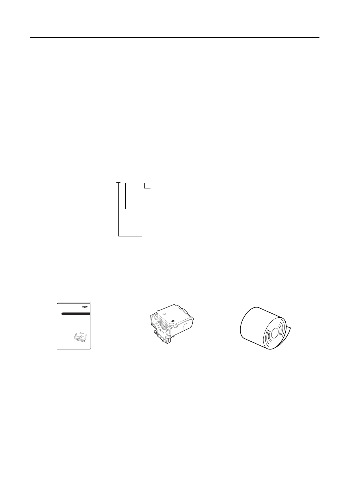
1.1 APPLICABLE MODEL
• BRST-10-1SF-QM
Model name description
B R S T - 1 0 - 1 S F - Q M
Destination Code
QM: Standard
1.2 ACCESSORIES
Owner's Manual
(EO1-13013)
TEC Ink Jet Printer
BRST-10 SERIES
Owner's Manual
TOSHIBA TEC CORPORATION
Cutter Type
F: Full Cut
S: Full & Stub Cut
Interface Type
S: Serial Interface
P: Parallel Interface
Head Unit/ Ink Cartridge
Receipt Roll
1-1
Page 7

2. SPECIFICATIONS
2. SPECIFICATIONS
2.1 PRINTER
EO1-13013
2.1 PRINTER
Model
Item
Supply voltage
Current consumption
Operating temperature
Relative humidity
Printing methods
Nozzle array
Print density
Direction of print
Print speed
Paper feed speed
Maximum print width
BRST-10-1SF-QM
+24 V DC – 5 % (Recommended Power Adapter : PS-10-QM)
1.5 A maximum
5 C to 35 C
10 % to 85 % RH (no condensation applies to the printer, not the paper)
Serial bubble jet
One row in length 128 nozzle
180 x 180 dots per inch
Bi-directional (The logic seek is possible.)
Receipt : 8.0 lines per second
Slip : 6.4 lines per second
20 lines per second
Receipt : 71.1 mm
Slip : 98.2 mm
Dimension
Weight
Standard interface
250 mm (width) x 307 mm (depth) x 148 mm (height)
4.0 kg
Serial interface (RS-232-C)
Drawer interface
2-1
Page 8
2. SPECIFICATIONS
5
5
5
5
5
123456789
1
9
1
9
1
9
123456789
2.2 RECEIPT PAPER
EO1-13013
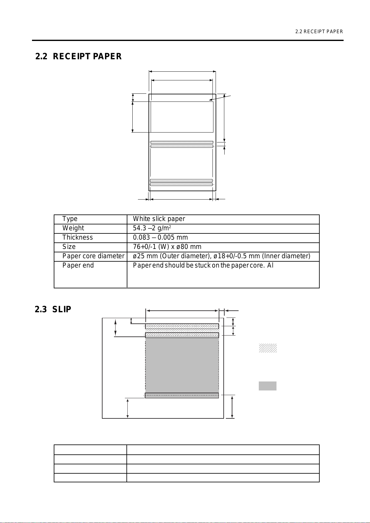
2.2 RECEIPT PAPER
76
71.1
9
36.1
Maximum Logo Print Area
NOTE: All dimensions are shown in
56.6
millimeters.
4.23
2.45
71.1 (42 digits)
2.45
Type White slick paper
Weight 54.3 –2 g/m
2
Thickness 0.083 – 0.005 mm
Size 76+0/-1 (W) x ø80 mm
Paper core diameter ø25 mm (Outer diameter), ø18+0/-0.5 mm (Inner diameter)
Paper end Paper end should be stuck on the paper core. Also, 1 to 1.5m
red mark should be marked on the paper within 2m from the
paper core.
Fig. 2-1
2.3 SLIP
10
3.4
98.2 (58 digits max)
23456789012345678901234567890121234
23456789012345678901234567890121234
23456789012345678901234567890121234
23456789012345678901234567890121234
23456789012345678901234567890121234
5.35
5.12
4.23
2345678
2345678
: indicates effective
2345678
print area, however,
smudges may occur
on the paper end.
: indicates
recommended
printing area.
21.7
23.4
Fig. 2-2
NOTE: Do not use folded paper or wrinkled paper. They may cause a paper jam or reduce print quality.
Type Ordinary paper (Only single paper is available.)
Thickness 0.07 to 0.14 mm
Weight 54.3 to 105 g/m
2
Size 68 to 215.9 mm (W) x 68 to 297 mm (L)
2-2
Page 9
3. OVERVIEW
3. OVERVIEW
3.1 FRONT/REAR VIEW
Slip Inlet
Front Cover
EO1-13013
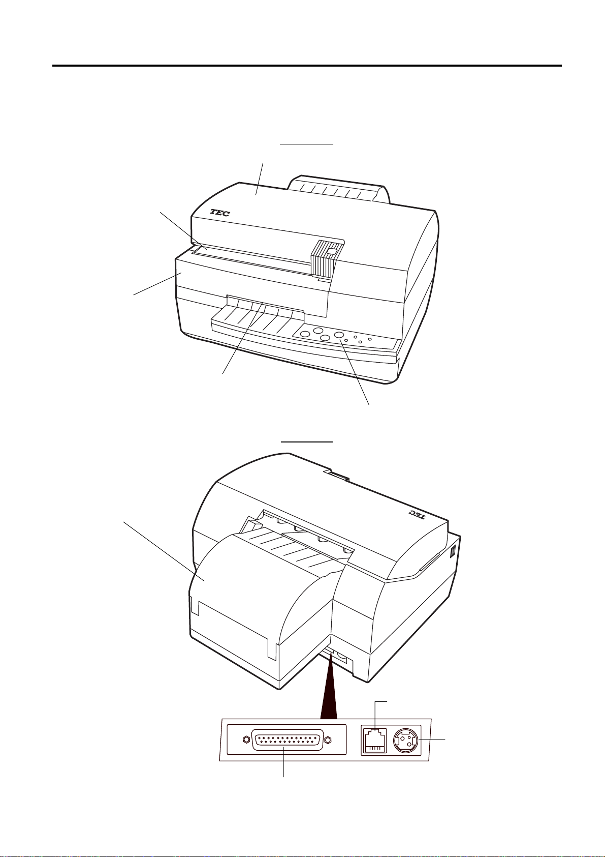
3.1 FRONT/REAR VIEW
Front View
Printer Cover
Paper Cover
Receipt Outlet
RESET
CART-
RIDGE
FEED
Rear View
POWER
POWER
ERROR
SLIP
INKOUT
Operation Panel
Fig. 3-1
Serial Interface Connector (RS-232C)
3-1
Drawer Interface
Connector
DC Power Inlet
Fig. 3-2
Page 10

3. OVERVIEW
3.2 OPERATION PANEL
56
CART-
RIDGE
RESET
FEED
78
POWER
2
1
SLIP
POWER
3
4
INKOUT
Fig. 3-3
ERROR
EO1-13013
3.2 OPERATION PANEL
11
1 POWER LED (Green)
11
On: Power is supplied.
Off: Power is not supplied.
Blinking: Ink is being initial operation when
the power turns ON.
22
2 SLIP LED (Green)
22
On: Slip mode
Off: Receipt mode
Blinking: Slip insertion wait state
33
3 INKOUT LED (Orange)
33
On: Ink-end detected
Off: Ink-end not detected (normal
status)
Blinking: Ink-near-end detected
44
4 ERROR LED (Red)
44
On: Paper jam error detected or
Cover open error detected or
Cutter error detected.
Off: Error not detected (normal status)
Blinking: Receipt paper end detected
55
5 POWER Switch
55
When turned on, the Power LED goes on and the printer is ready to print.
When turned off, the head unit/ ink cartridge is moved to the cleaning position and is capped. The
POWER LED is turned off.
If turned off during printing, the print data is lost.
At the moment the power is supplied from the external power supply unit, the printer is in the condition
of Power off (LED not lit) until the power switch is pressed.
When the first time the power is turned on with the external power supply unit, the initial operation is
performed.
66
6 RESET Switch
66
If you press and hold this switch for a few seconds, the initial operation is performed.
NOTE: Clean the head unit only when it becomes dirty or a dot missing occurs. Unnecessary
cleaning will waste ink.
77
7 FEED Switch
77
Used for feeding the receipt and the slip.
If there is a slip, the slip is fed.
If not, the receipt paper is fed.
88
8 CARTRIDGE Switch
88
Used for changing the ink cartridge or the head unit/ ink cartridge.
When the switch is pressed with the printer cover removed, the carriage is moved to the head unit/ ink
cartridge replacement position.
Press this switch again after changing the ink cartridge or the head unit/ ink cartridge, and the carriage
is moved to home position and the initial operation is performed.
3-2
Page 11

4. SET UP PROCEDURE
4.1 REQUIREMENTS FOR OPERATION
EO1-13013
4. SET UP PROCEDURE
4.1 REQUIREMENTS FOR OPERATION
This printer has the following requirements:
• The ECR or POS terminal must have a serial port.
• To communicate with the ECR or POS terminal, an RS-232C cable is required.
RS-232C cable ................25 pins
■ Interface Cables
Use the serial printer cable CBLST-50-2-QM supplied by TOSHIBA TEC or its equivalent.
To prevent radiation and reception of electrical noise, the interface cables must meet the following
requirements:
• Fully shielded and fitted with metal or metalised connector housings.
• Kept as short as possible.
• Should not be bundled tightly with power cords.
• Should not be tied to power line conduits.
NOTE: Use the RS-232C cable which connector securing screws are inch type.
Controller side
D-SUB 9-pin female
PIN-No
Case
2
3
8
4
5
6
Signal
FG
RXD
TXD
CTS
DTR
GND
DSR
Printer side
D-SUB 25-pin male
PIN-No
1
2
3
4
6
7
20
Signal
FG
TXD
RXD
RTS
DSR
SG
DTR
4.2 SETTING UP THE PRINTER
• Place the printer on a flat, stable surface.
• Use a grounded electrical outlet. Do not use an adapter plug.
• Be sure there is adequate room around the printer for easy operation and maintenance.
• Keep your work environment static free.
4-1
Page 12

5. INSTALLATION PROCEDURE
5.1 CONNECTING THE POWER CORD AND CABLES
5. INSTALLATION PROCEDURE
WARNING!
1. Before connecting the power cord and cables to the printer, turn the power of the ECR or POS
terminal OFF.
2. To avoid injury and printer damage, be careful not to catch your fingers or any objects while the
carriage moves right and left in the initial performance.
3. Please be careful when handling ink cartridges, not to get ink on your hands or in your eyes.
If you accidently get ink on your hands wash them with soap and water. If any ink should get
into your eyes immediately flush them out with clear water.
4. Never touch the metal portion of the head unit/ ink cartridge. Doing so will injure your fingers.
CAUTION:
1. Do not put anything on the printer cover and never press on it.
2. Use only TOSHIBA TEC specified paper. Use of non-specified paper may lower the print
quality or shorten the cutter life.
3. Set the receipt roll in the correct direction. Failure to do this may cause a paper jam error.
4. Do not drop or shake the head unit/ ink cartridge. Doing so may cause ink to spill over. Once
ink gets on your clothes, it cannot be removed.
EO1-13013
Operation panel
indication:
SWITCH
POWER
LED
: LED off
: Not depressed.
: LED on
POWER
: Depressed.
: LED blinking
5.1 CONNECTING THE POWER CORD AND CABLES
NOTE: Please use the TEC PS-10-QM AC adapter. To purchase it, please contact your nearest
TOSHIBA TEC service representative.
1. Connect the serial interface cable (corresponding to inch screws) to the printer.
2. If the EPSON* drawer is connected, connect the drawer interface cable.
3. Connect the power cord so that the D cut section faces up.
4. Plug in the AC adapter. The printer performs initial operation.
Serial Interface Cable
(RS-232C)
to Host
to EPSON Drawer
to AC Adapter
Drawer interface Cable
DC Power Cable
* EPSON is a trademark of SEIKO EPSON CORPORATION.
5-1
Fig. 5-1
Page 13

5. INSTALLATION PROCEDURE
5.2 LOADING THE HEAD UNIT/ INK CARTRIDGE
1. Open the printer cover while holding the handle, and remove it.
Printer Cover
CAUTION
Do not put anything
on the cover and
never press it.
* The above sticker is attached
to the printer cover.
Pressing the cover may
reduce print quality.
EO1-13013
5.2 LOADING THE HEAD UNIT/ INK CARTRIDGE
2. Turn the power ON by pressing and holding the
[POWER] switch. The carriage automatically moves
to the head unit/ ink cartridge replacement position.
Carriage
CART-
RIDGE
RESET
FEED
POWER
SLIP
POWER
Fig. 5-2
ERROR
INKOUT
Fig. 5-3
5-2
Page 14

5. INSTALLATION PROCEDURE
5.2 LOADING THE HEAD UNIT/ INK CARTRIDGE
EO1-13013
3. Unpack a head unit/ ink cartridge. Remove the protection pad from the head unit/ ink cartridge. 1
4. Remove the protection sheet from the head unit/ ink cartridge. 2
NOTES: 1. Do not touch the area that had been under the protection sheet with your fingers or with any
object.
2.To avoid the head unit/ ink cartridge from which the protection sheet has been removed from
getting dry, install it into the printer as soon as possible after removing the protection sheet.
3.Do not install the head unit/ ink cartridge with the protection pad and the protection sheet
attached. Doing so will damage the printer.
4.Do not remove the protection sheet while the head unit/ ink cartridge faces down. Also do
not drop or shake the head unit/ ink cartridge. Doing so may cause ink to spill over. Once
ink gets on your clothes, it cannot be removed.
Protection pad
1
2
Protection Sheet
Fig. 5-4
5. Load the head unit/ ink cartridge onto the carriage, and then fully push it in the arrow-indicated
direction until the hook secures the cartridge.
Head Unit/ Ink Cartridge
Hook
Carriage
5-3
Fig. 5-5
Page 15

5. INSTALLATION PROCEDURE
EO1-13013
5.3 LOADING THE RECEIPT ROLL
6. Depress the [CARTRIDGE] switch.
The printer performs the initial operation. After the initial
operation is finished, the carriage returns to the home
position (right end).
CART-
RIDGE
RESET
FEED
POWER
SLIP
POWER
ERROR
INKOUT
7. Insert the two hooks into the holes on the top cover, and then close the printer cover slowly.
Printer Cover
Hooks
Top Cover
Fig. 5-6
5.3 LOADING THE RECEIPT ROLL
1. Open the paper cover toward the rear 1.
2. Cut off both adhesive areas of a new receipt roll.
NOTE: Do not insert the receipt paper with adhesive portions into the printer. If so, adhesive will
attach to the feed roller. This may cause a slant print or a paper jam.
Adhesive
Adhesive
Fig. 5-7
5-4
Page 16

5. INSTALLATION PROCEDURE
3. Load the receipt roll into the paper holder as the figure shows. 2
Receipt Roll
Paper Cover
EO1-13013
5.3 LOADING THE RECEIPT ROLL
NOTE:
Set the receipt roll in correct
direction.
Cut the paper end to make it
sharp.
4. Insert the receipt straight into the receipt inlet. 3
The auto loading mechanism feeds and cuts the receipt automatically.
NOTE: If the rear paper release lever is not pushed down, the
auto loading mechanism does not perform.
The ERROR LED turns off, and the printer becomes ready to
print.
Receipt Inlet
3
Rear Paper Release
Lever (blue)
CART-
RIDGE
RESET
FEED
POWER
SLIP
POWER
Fig. 5-8
ERROR
INKOUT
Fig. 5-9
5. Close the paper cover slowly.
5-5
Page 17

5. INSTALLATION PROCEDURE
5.4 INSERTING THE SLIP
EO1-13013
5.4 INSERTING THE SLIP
1. When the host sends the slip print command to the printer,
the SLIP LED blinks.
2. Insert the slip straight into the slip inlet while aligning the
right side of the slip with the slip inlet.
Slip Inlet
Slip
CART-
RIDGE
CARTRIDGE
RESET
RESET
FEED
FEED
POWER
POWER
POWER
SLIP
POWER
SLIP
ERROR
INKOUT
ERROR
INKOUT
Fig. 5-10
NOTES: 1.
Setting the slip
Paper feed roller
Slip side guide
Slip
Fig. 5-11
• Insert the slip until it fits against the paper feed roller and the slip side guide.
• Setting the slip after the SLIP LED blinks is recommended.
2. Slip paper
• Use the flat paper which is not curled, folded, warped, or wrinkled. Failure to do
this may cause ink smudge resulting from contact with the ink cartridge or a paper
feed error after printing. If the paper end is much curled or folded, the slip paper
may not be set. (In this case, the printer feeds the paper.)
3. Removing the jammed slip
• Check the SLIP LED blinks, and then remove the jammed paper with the [FEED]
switch.
• If the paper cannot be removed with the [FEED] switch, open the printer cover and
pull out the jammed paper manually.
5-6
Page 18

6. REPLACING THE RECEIPT ROLL
6. REPLACING THE RECEIPT ROLL
EO1-13013
6. REPLACING THE RECEIPT ROLL
To replace the receipt roll and to release a paper jam, the following steps should be followed.
WARNING!
To avoid injury and printer damage, be careful not to catch your fingers or any objects while the
carriage moves right and left in the initial performance.
CAUTION:
1. Use only TOSHIBA TEC specified paper. Use of non-specified paper may lower the print
quality or shorten the cutter life.
2. Set the receipt roll in the correct direction. Failure to do this may cause a paper jam error.
1. Turn the power OFF by pressing and holding the [POWER] switch.
2. Open the printer cover while holding the handle, and remove it. (Refer to Section 5.2 LOADING THE
HEAD UNIT/ INK CARTRIDGE)
3. While pushing the front cover in direction 1, remove it in direction 2.
4. Open the paper cover backward. 3
Paper Cover
3
Front Cover
1
2
Fig. 6-1
6-1
Page 19

6. REPLACING THE RECEIPT ROLL
EO1-13013
6. REPLACING THE RECEIPT ROLL
5. Pull up the rear paper release lever (blue). 4
6. Push down the front paper release lever in direction 5, and then remove the receipt roll in direction 6.
Rear Paper Release Lever (blue)
4
6
5
Front Paper Release Lever
Fig. 6-2
7. Return the front cover.
8. Pull down the rear paper release lever (blue).
9. Insert the two hooks into the holes on the top cover, and then close the printer cover slowly.
10.Turn the power ON by pressing and holding the [POWER]
switch.
The POWER LED and ERROR LED turn on.
CARTRIDGE
RESET
FEED
POWER
SLIP
POWER
ERROR
INKOUT
11.Put the new receipt roll into the paper holder. (Refer to Section 5.3 LOADING THE RECEIPT ROLL)
12.Insert the receipt straight into the receipt inlet.
The auto loading mechanism feeds and cuts the receipt automatically.
The ERROR LED turns off, and the printer becomes
ready to print.
13.Close the paper cover slowly.
CART RIDGE
RESET
FEED
POWER
SLIP
POWER
ERROR
INKOUT
6-2
Page 20

7. REPLACING THE INK CARTRIDGE
7. REPLACING THE INK CARTRIDGE
7. REPLACING THE INK CARTRIDGE
The INKOUT LED on or blinking shows that ink is getting
low. The printer can print until ink is fully finished, however,
please replace the ink cartridge with a new one earlier.
CART-
RIDGE
RESET
POWER
FEED
WARNING!
1. To avoid injury and printer damage, be careful not to catch your fingers or any objects while
the carriage moves right and left in the initial performance.
2. Please be careful when handling ink cartridges, not to get ink on your hands or in your eyes.
If you accidently get ink on your hands wash them with soap and water. If any ink should get
into your eyes immediately flush them out with clear water.
CAUTION:
1. Do not put anything on the printer cover and never press on it.
2. Do not drop or shake the head unit/ ink cartridge. Doing so may cause ink to spill over. Once
ink gets on your clothes, it cannot be removed.
POWER
SLIP
or
EO1-13013
ERROR
INKOUT
1. Remove the printer cover. (Refer to 5.2 LOADING THE HEAD UNIT/ INK CARTRIDGE.)
2. Depress the [CARTRIDGE] switch for 3 seconds.
By this operation, the carriage moves to the head unit/ ink
cartridge replacement position.
NOTES: 1. If the printer cover is closed, the carriage will
CART-
RIDGE
RESET
FEED
POWER
SLIP
POWER
ERROR
INKOUT
not move to this position by this operation.
2. Never perform this operation except for the
or
ink cartridge replacement.
Carriadge
Fig. 7-1
3. While pushing the hook in direction 1, remove the ink cartridge from the head unit in diretion 2.
Ink Cartridge
2
Hook
1
7-1
Fig. 7-2
Page 21

7. REPLACING THE INK CARTRIDGE
7. REPLACING THE INK CARTRIDGE
EO1-13013
4. Unpack a new ink cartridge. Pull down both arrow sections remove the protection pad from the
cartridge.
NOTES: 1. Do not touch the ink outlet on the bottom of the ink cartridge with your fingers or any
objects.
2.To avoid the ink cartridge from which the protection pad has been removed from getting
dry, install it into the head unit as soon as possible after removing the protection pad.
3.Do not drop or shake the head unit/ ink cartridge. Doing so may cause ink to spill over.
Once ink gets on your clothes, it cannot be removed.
Protection Pad
Ink Cartridge
Fig. 7-3
5. Insert the ink cartridge into the head unit so that the black and yellow arrows on the ink cartridge line
up with the black and yellow arrows on the carriage.
NOTE: When installing the ink cartridge into the head unit, fully push the ink cartridge until the hook
secures the cartridge.
Head Unit
Carriage
Black arrow
Yellow arrow
Fig. 7-4
Hook
6. Depress the [CARTRIDGE] switch.
The printer performs the initial operation. After the initial
operation is finished, the carriage returns to the home position
(right end), and the power LED stops blinking and remains
on.
7. Insert the two hooks into the holes on the top cover, and then
close the printer cover slowly. The ERROR LED turns off,
and the printer becomes ready to print.
NOTE: Failure to close the printer cover fully may cause an
error condition.
7-2
CART-
RIDGE
CART-
RIDGE
RESET
RESET
FEED
FEED
POWER
POWER
SLIP
SLIP
POWER
POWER
ERROR
INKOUT
ERROR
INKOUT
Page 22

8. REPLACING THE HEAD UNIT/ INK CARTRIDGE
8. REPLACING THE HEAD UNIT/ INK CARTRIDGE
EO1-13013
8. REPLACING THE HEAD UNIT/ INK CARTRIDGE
If the head unit gets dirty or a dot missing occurs, clean the head unit. (Refer to 9.1 CLEANING)
If these phenomena still remain, replace the head unit/ ink cartridge with a new one by the following
procedure.
WARNING!
1. To avoid injury and printer damage, be careful not to catch your fingers or any objects while the
carriage moves right and left in the initial performance.
2. Please be careful when handling ink cartridges, not to get ink on your hands or in your eyes. If
you accidently get ink on your hands wash them with soap and water. If any ink should get into
your eyes immediately flush them out with clear water.
3. Never touch the metal portion of the head unit/ ink cartridge. Doing so will injure your fingers.
CAUTION:
1. Do not put anything on the printer cover and never press on it.
2. Do not drop or shake the head unit/ ink cartridge. Doing so may cause ink to spill over. Once
ink gets on your clothes, it cannot be removed.
1. Turn the power ON by pressing and holding the [POWER]
switch.
CART-
RIDGE
RESET
FEED
POWER
SLIP
POWER
ERROR
INKOUT
2. Remove the printer cover. (Refer to 5.2 LOADING THE HEAD UNIT/ INK CARTRIDGE.)
3. Depress the [CARTRIDGE] switch for 3 seconds. By this operation, the carriage moves to the head
unit/ ink cartridge replacement position. (Refer to 7. REPLACING THE INK CARTRIDGE)
NOTES: 1. If the printer cover is closed, the carriage will not move to this position by this operation.
2. Never perform this operation except for the head unit/ ink cartridge replacement.
4. Remove the head unit/ ink cartridge from the carriage while pulling up the hook in the arrow-indicated
direction.
Head Unit/ Ink Cartridge
Carriage
8-1
Hook
Fig. 8-1
Page 23

8. REPLACING THE HEAD UNIT/ INK CARTRIDGE
8. REPLACING THE HEAD UNIT/ INK CARTRIDGE
EO1-13013
5. Unpack a new head unit/ ink cartridge. Remove the protection pad from the head unit/ ink cartridge. 1
6. Remove the protection sheet from the head unit/ ink cartridge. 2
NOTES: 1. Do not touch the area that had been under the protection sheet with your fingers or with any
object.
2.To avoid the head unit/ ink cartridge from which the protection sheet has been removed from
getting dry, install it into the printer as soon as possible after removing the protection sheet.
3.Do not install the head unit/ ink cartridge with the protection pad and the protection sheet
attached. Doing so will damage the printer.
4.Do not remove the protection sheet while the head unit/ ink cartridge faces down. Also do
not drop or shake the head unit/ ink cartridge. Doing so may cause ink to spill over. Once
ink gets on your clothes, it cannot be removed.
Protection pad
1
2
Protection Sheet
Fig. 8-2
7. Load the head unit/ ink cartridge onto the carriage, and then fully push it until the hook secures the
cartridge. (Refer to 5.2 LOADING THE HEAD UNIT/ INK CARTRIDGE)
8. Depress the [CARTRIDGE] switch.
The printer performs the initial operation. After the initial
operation is finished, the carriage returns to the home
CART-
RIDGE
RESET
FEED
POWER
SLIP
POWER
ERROR
INKOUT
position (right end), and the power LED stops blinking and
remains on.
9. Insert the two hooks into the holes on the top cover, and then
close the printer cover slowly. The ERROR LED turns off,
and the printer becomes ready to print.
CART-
RIDGE
RESET
FEED
POWER
SLIP
POWER
ERROR
INKOUT
NOTE: Failure to close the printer cover fully may cause an
error condition.
8-2
Page 24

9. GENERAL MAINTENANCE
9.1 CLEANING
9. GENERAL MAINTENANCE
WARNING!
1. Be sure to disconnect the power cord prior to performing any maintenance.
2. Do not use any tool that may damage the head unit.
3. DO NOT POUR WATER directly onto the printer.
CAUTION:
1. Do not use a sharp object to clean the head unit. Doing so may damage the head unit, causing
poor print quality or missing dots.
2. Never use an organic solvent like thinner or benzine for cleaning. Using such solvents may
discolor the covers, cause poor print quality, or printer failure.
3. Do not touch the head unit nozzle, as the head unit may fail due to static electricity.
EO1-13013
9.1 CLEANING
9.1.1 Cover and Paper Path
To help retain the high quality and performance of your printer it should be cleaned regularly . The
greater the usage on the printer, the more frequent the cleaning.
1. Turn the power off.
2. Wipe the covers with a dry soft cloth. Clean stains on the covers with a soft cloth slightly
moistened with a mild detergent solution. After that, wipe the covers with a soft moist cloth.
3. Remove dust or paper particles with a slightly moistened soft cloth or air brush.
9.1.2 Head Unit
If the head unit becomes dirty or a dot missing occurs, clean the head unit in the following
procedure.
NOTE: Clean the head unit only when it becomes dirty or a dot missing occurs. Unnecessary
cleaning will waste ink.
1. Turn the power on.
2. Depress and hold the [RESET] switch. Then, the printer performs the head cleaning process
automatically.
9.2 REMOVING JAMMED PAPER
1. Turn the power off.
2. Remove the printer cover. (Refer to 5.2 LOADING THE HEAD UNIT/ INK CARTRIDGE)
3. Remove the front cover. (Refer to 6. REPLACING THE RECEIPT ROLL)
4. Open the paper cover foward the rear.
5. Pull up the rear paper release lever (blue).
6. Remove the jammed paper while pushing down the front paper release lever.
9-1
Page 25

10. TROUBLESHOOTING
10. TROUBLESHOOTING
10.TROUBLESHOOTING
WARNING!
If you cannot solve a problem with the following solutions, do not attempt to repair it yourself. Turn
the power off, unplug the printer, then contact your TOSHIBA TEC representative for assistance.
EO1-13013
Symptom
The power does not turn
on.
Receipt paper or Slip is not
issued.
No print however the
POWER LED lights.
Check Point
• Is the power cord plugged in
correctly?
• Is the power supplied to the AC
outlet?
• Has the fuse or circuit breaker
blown?
• Is the receipt roll loaded
properly?
• Is the printer jammed with the
receipt?
• Is the interface cable connected
correctly?
• Does the specifications of the
interface cable meet that of the
host or the printer?
Solution
• Plug in correctly.
• If it is not a power failure, check
for the power supply to the AC
outlet with another electric
appliance. When the power is
not supplied, contact your
nearest power company.
• Check the fuse or circuit
breaker.
• Refer to page 6-1 and load the
receipt roll properly.
• Refer to page 9-1 and remove
the jammed receipt, and reload
the receipt roll.
• Connect the interface cable
correctly.
• Use a TOSHIBA TEC original
interface cable.
Dim print
• Is ink getting low?
• Refer to page 9-1 and clean the
head unit. If this problem still
occurs, replace the ink cartridge
with a new one.
One print line missing
• Is the head unit dirty?
Is ink getting low?
• Refer to page 9-1 and clean the
head unit. If this problem still
occurs, replace the ink cartridge
or head unit/ ink cartridge with a
new one.
Irregular print/ blurred print
• Is proper paper used?
• Refer to page 2-2 and use the
TOSHIBA TEC specified paper.
Paper feed slantwise
• Is the paper damp?
• Is the paper folded or wrinkled?
• Do not use damp paper.
• Do not use old paper or folded
paper. Use a new one.
• Is the paper damp?
• Do not use damp paper.
If any problem occurs excepting the above, please contact your nearest TOSHIBA TEC representative.
10-1
Page 26

11. ERROR MESSAGE
11. ERROR MESSAGE
Error Item
Ink end
Ink near end
No head
Head temperature
No receipt paper (Receipt paper ended.)
11. ERROR MESSAGE
PANEL-LED Display
ERROR
POWER
INKOUT
SLIP
ERROR
POWER
INKOUT
SLIP
ERROR
POWER
INKOUT
SLIP
ERROR
POWER
INKOUT
SLIP
ERROR
POWER
INKOUT
SLIP
EO1-13013
The receipt paper exists but is not loaded automatically.
Slip jam (issue)
Printer cover open or Front cover open
Cutter position
Head position
Temperature
Receipt jam (at the auto loading)
ERROR
POWER
INKOUT
SLIP
ERROR
POWER
INKOUT
SLIP
ERROR
POWER
INKOUT
SLIP
ERROR
POWER
INKOUT
SLIP
ERROR
POWER
INKOUT
SLIP
ERROR
POWER
INKOUT
SLIP
ERROR
POWER
INKOUT
SLIP
ERROR
While returning at the printer power ON
Slip is required.
Head Unit / Ink Cartridge replacement has not been
finished yet.
POWER
INKOUT
SLIP
ERROR
POWER
INKOUT
SLIP
ERROR
POWER
INKOUT
SLIP
NOTE: In case other combination of LEDs except for the above light or blink, turn the power off,
and then turn the power on. If this does not restore the LEDs, contact your nearest
TOSHIBA TEC representative for assistance.
11-1
Page 27

Page 28

TEC
 Loading...