

Page 1

INSTALLATION MANUAL
TOUCH SCREEN CONTROLLER
for Air Conditioning Control System
Model: BMS-TP0641ACE
BMS-TP0641PWE
BMS-TP5121ACE
BMS-TP5121PWE
• Thank you very much for purchasing the TOSHIBA Touch Screen Controller.
• Please read this manual carefully beforehand for proper installation of the controller.
CONTENTS
Precautions for Safety.................................................................................................................... 1
Introduction ..................................................................................................................................... 2
Before Installation .......................................................................................................................... 3
1 Installation .................................................................................................................................... 3
2 Connection of Power cables/Earth wires/Signal wires ........................................................... 5
3 Trial Operation ............................................................................................................................. 8
Page 2
Precautions for Safety
• Read these "Precautions for Safety" carefully before installation.
• The precautions described below include important items regarding safety. Observe them without fail.
• After the installation work, perform a trial operation to check for any problem. Follow the Owner's
Manual to explain how to use and maintain the unit to the customer. Ask the customer to keep this
Installation Manual together with the Owner's Manual.
WARNING
• Ask an authorized dealer or qualified installation professional to install or reinstall the Touch
Screen Controller.
Improper installation may result in electric shock or fire.
• Turn off the main power supply switch or breaker before attempting any electrical work.
Make sure all power switches are off. Failure to do so may cause electric shock.
• Perform installation work properly according to this Installation Manual.
Improper installation may result in electric shock or fire.
• Do not modify the unit.
Any modification may cause a malfunction, resulting in overheating or fire.
CAUTION
Upon customer’s approval, install the Touch Screen Controller at a place which satisfies the
following conditions.
• Place where the Touch Screen Controller can be installed securely.
• Place which can reserve a sufficient service space for safe maintenance or check.
• Place where CF (Compact Flash) card can be removed easily.
• Place which provides sufficient space for connecting/checking the terminals of interface, Input-
Output ports, etc.
Avoid the following places.
• Places where a device generating high frequency (inverter, non-utility generator, medical apparatus,
or communication equipment) is installed. (A bad influence may generated by malfunction of the
controller, control error, or noise may affect such equipment.)
• Perform wiring correctly in accordance with specified the current capacity.
Failure to do so may result in short-circuiting, overheating, or fire.
• Connect the specified cables for the terminals securely to prevent external forces from
affecting them.
Failure to do so may result in disconnection, overheating, or fire.
1
Page 3
Introduction
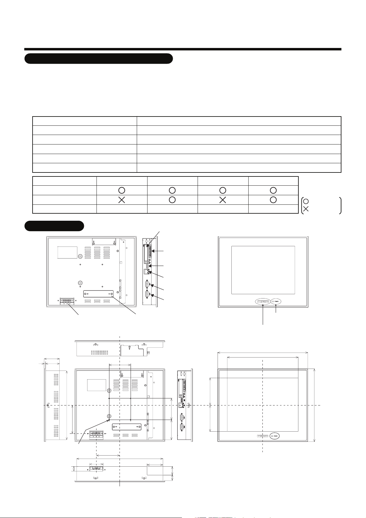
Applications/Functions/Specifications
Applications/Functions
•
The Touch Screen Controller is equipped with the LCD display and the touch panel and has various
functions such as operation control, operation status monitoring, scheduled operation, and error code
display of up to 64 or 512 indoor units.
Specifications
•
Power supply
Power consumption
Operating temperature/humidity
Storage temperature
Dimensions
Mass
BMS-TP0641ACE BMS-TP0641PWE BMS-TP5121ACE BMS-TP5121PWE
Air conditioning control
Power distribution
Indoor units connected
Max. 64 units Max. 64 units Max. 512 units Max. 512 units
100 - 240 VAC, 50/60Hz
50VA
0°C to 50°C, 20% to 85% RH (no condensation)
-10°C to +60°C
256 (H) × 316 (W) × 54 (D) mm
3.5kg
: available
: Not available
External View
54
549
242
Power input
terminal block
75
CF (Compact Flash)
card slot (CF card for
data files)
Input/Output port
USB
Ethernet
COM1(RS-232C)
COM2(RS-485)
PCI expansion unit
connector cover
POWER LED
Function switch (F1, F2, F3)
316
249
95.7591.75
256
99.3
M4 Tap (×4 pcs.)
(depth: 10 mm max.)
16
48
82.5
302
55.5
70 75
19 30
unit: mm
2
Page 4

Before Installation
Check the following package contents.
No.
1
Touch Screen Controller
2
Fixture
3
CF(compact flash) for data file
4
CF adapter
5
Simple stand
6
Triangle thread screw (M4 × 8, Ni)
7
Card cover
8
Triangle thread screw (M3 × 6, Ni)
9
RS-485 cable
10
Installation Manual
Use the following materials to connect the signal lines and power lines. (procured on site)
No.
For RS-485
1
For digital Input/Output connection
2
For Power
3
Item
Line
Quantity
1
6
1
1
1
1
1
1
1
1
Type
Wire size
Length
Type
Wire size
Length
Type
Wire size
Remarks
For fixing the unit at pannel mount
It is inserted in the CF card slot of controller at shipment.
(For data file)
It is inserted in the CF card slot of controller at shipment.
For simple stand
For preventing CF(compact flash) from coming out
For card cover
For connecting controller and TCS-NET Relay Interface
This manual
Description
2-core shield wire
1.25mm2, 500m max. (total length)
2-core wire, 0.3mm2, 100m max
H07 RN-F or 245IEC66
0.75mm2, 50 m max.
1
Installation
Installation Space and Maintenance Space
Space 30mm or more in between the controller and surrounding objects.
Make space for service.
Panel
30 mm or more (top)
30 mm or more (side)
Bottom view
30 mm or more (bottom)
30 mm or more (rear)
Side view
Interface side
Panel
3
Page 5

Installation Method
Two installation methods are provided. One is the panel mount with the fixture. The other is the desk top
installation using the CONTEC stand (procured on site).
(1) Panel Mount
How to install the fixture
1. Insert the controller from outside of the panel.
Panel cut size
+1
303
-0
R1 or less
+1
-0
243
Panel thickness: 1.6 - 7 mm
2. Insert the fixtures from inside of the panel.
Touch Screen
Controller
Panel
Fixture
Tightening screws excessively
may cause the screws to break.
Optimum tightening torque for
good waterproofing effect is
0.6N/m.
REQUIREMENT
Use a panel
(procured on site) of
thickness 1.6-7 mm.
(2) Desk Top Installation using the CONTEC stand (procured on site)
75 mm
75 mm
The angle adjustment lock screw.
(Loosen the screw and adjust angle.)
For reference
Display stand (not supplied with the controller)
Use the CONTEC stand (model: IPC-SND-03).
For details of the stand, visit the CONTEC web site.
Europe: http://www.contec-europe.com/
China: http://www.contec.sh.cn/
[mm]
REQUIREMENT
Do not install the unit in any of the following places.
• Humid or wet place
• Dusty place
• Place exposed to direct sunlight
• Place where there is a TV set or radio within one meter
• Place exposed to rain (outdoors, under eaves, etc.)
4
Page 6

Connection of Power cables/Earth wires/
2
Signal wires
Connect cables to the connectors and terminals specified.
REQUIREMENT
Power cable is not supplied for the Touch Screen Controller. Prepare a 3-pin power cable conforming
to applicable safety standards. Be sure to connect the earth line earth of the power cable securely.
Digital Input
Digital Output
For details of the connection,
refer to I/O port connection
on next page.
Ethernet
(To customer's PC)
Power input terminal
L
N
Power supply
Length of stripped
power cable
Connect firmly the power
cable to the power input
terminal.
35 10
45 10
COM2 Ethernet I/O port
Connect the attached
RS-485 cable to COM2.
COM2 (RS-485)
(TCS-NET relay interface)
Length of stripped digital
Input/Output connector wire
35 10
CAUTION
• Ensure to connect the breaker to the primary side of power.
5
Page 7

Connection of Power cables/Earth wires/
2
Signal wires
(continued)
I/O Port Connection
The I/O Port is used to control air conditioners by interlocking them with electric lock signals and fire alarm
signals, and to transmit air conditioner failures to other devices.
I/O Port
10 1
↓ Front (LCD side)
Pin No. Signal name
1
2
3
4
5
6
7
8
9
10
PI_PCOM
PI(0)
PI(1)
PI(2)
P_PO(0)
N_PO(0)
P_PO(1)
N_PO(1)
P_PO(2)
N_PO(2)
Input plus common
Input 0
Input 1
Input 2
Output 0+
Output 0-
Output 1+
Output 1-
Output 2+
Output 2-
Remarks
Input/Output specifications
Input
Output
Input type
Number of input
Input resistance
Output type
Number of output
Output current
Output voltage
Photo-coupler insulation
3
3k ohm
Open collector
3
Max. 100mA (per 1 output)
Less than 30V DC
(1) The example of input circuit is shown below.
It is electrically insulated by the photo-coupler.
PI_PCOM
10 k ohm
3 k ohm
1/2 W
PI(0) - PI(2)
Input/Output
connector
Input c
ontact
External power supply
(12 V - 24 V DC)
(2) The example of output circuit is shown below.
It is electrically insulated by the photo-coupler.
(External circuit)
330 ohm
PC357
P_PO(0) - P_PO(2)
2SD780A
4.7 k ohm
N_PO(0) - N_PO(2)
Input/Output
connector
load
External power
supply
(Max. 30 V DC)
6
Page 8

Connection of Power cables/Earth wires/
2
Signal wires
(continued)
The example of the system wiring connection is shown below.
Terminator Resistor Setting
RS-485 terminator resistor
•
The terminator resistors of RS-485 are set at both ends of communication cable. The RS-485
terminator resistor (at one end) of the Touch Screen Controller is set at shipment. No setting is needed.
SW6
ON
TCC-LINK
TERMINATOR
12
SW5
ON
RS-485
TERMINATOR
1
2
RS-485
TCS-NET RELAY
INTERFACE
SW6
ON
TCC-LINK
TERMINATOR
12
SW5
ON
RS-485
TERMINATOR
1
2
RS-485
TCS-NET RELAY
INTERFACE
ADDRESS
ADDRESS
U4U3
SW1
8
U2U1
Outdoor
unit
U2U1
U2U1
Indoor unit
Remote
controller
U4U3
U2U1
Outdoor
SW1
1
unit
U2U1
Remote
controller
U2U1
Indoor unit
Outdoor
unit
Indoor unit
Remote
controller
Outdoor
unit
Indoor unit
Remote
controller
U4U3
U2U1
U2U1
U4U3
U2U1
U2U1
U4U3
Indoor unit
U4U3
Indoor unit
Yellow
A
Caution:
RS-485 cable has polarity.
If incorrectly connected, it
does not work.
Red
Brown
B
Crimp 3 wires with
a closed end wire joint.
Orange
A
B
Red/Orange
Brown/Yellow
Power supply
Power supplyPower supplyPower supply
TCC-LINK
TCC-LINK
FG
U1U2
ABLNLNLN LN
FG
U1U2
AB
Central remote
controller
Central remote
controller
TOUCH SCREEN
CONTROLLER
Switching HUB
Customer's PC
SW1
4
ADDRESS
DIGITAL I/O
INTERFACE
SW1
1
ADDRESS
ENERGY
MONITORING
INTERFACE
DI 1
DI 2
DI 3
DI 4
DI 5
DI 6
DI 7
DI 8
DI 1
DI 2
DI 3
DI 4
DI 5
DI 6
DI 7
DI 8
Input contact 1
Input contact 2
Input contact 3
Input contact 4
Input contact 5
Input contact 6
Input contact 7
Input contact 8
Load 1
DO1
DO2
DO3
DO4
GND
+12V
BA BA
RS-485 RS-485
Load 2
Load 3
Load 4
Power meter 1
Power meter 2
Power meter 3
Power meter 4
Power meter 5
Power meter 6
Power meter 7
Power meter 8
The setting of the Touch Screen Controller is done at shipment. No setting is required.
7
Page 9

3
•
•
•
•
Trial Operation
Before Trial operation
Setting File Creation
The setting file is necessary to use the Touch Screen Controller.
Please inquire of your local sales office about it.
The setting file will be copied to the Compact Flash card inserted in the CF slot of the Touch Screen
Controller.
Trial Operations of Air Conditioner and Each Interface
Confirm the trial operations of the air conditioner and the each interface. And turn on the power of each
device.
Trial operation
Start-up of the Touch Screen Controller
Connect the power cable, earth wire and signal wire of the Touch Screen Controller.
Insert the compact flash containing the setting file in the CF slot and turn on the power.
The initial screen appears.
Initialization
It is necessary to initialize the system to make the setting file effective.
Operational Procedure
(1) Press the [MENU] button. The menu screen appears.
(2) Press the [SYSTEM RESET] button on the menu screen.
The message to confirm the operation appears. Press [Yes] to execute.
Then, the system re-starts up.
Confirmation of Communication with Each Interface
•
When the communication with the interface listed on the setting file is disconnected, the communication
error is displayed on the Touch Screen Controller. Press the [Alarm List] button to confirm whether the
communication error occurs or not. (Communication error judging time: Approx. 15 minutes)
The suspected causes of the communication error will be as follows.
• The interface is not powered.
• The address setting of the interface is incorrect.
• The communication between the Touch Screen Controller and the interface is disconnected.
• The setting file is incorrect.
Confirmation of Communication with Air Conditioner
•
When the communication with the air conditioner is disconnected, the communication error is displayed
on the Touch Screen Controller. The frame of air conditioner button on the screen is displayed orange.
The suspected causes of the communication error will be as follows.
• The air conditioner is not powered.
• The address setting of the air conditioner is incorrect.
• The communication between the TCS-NET relay interface and the air conditioner is disconnected.
• The communication between the Touch Screen Controller and the TCS-NET relay interface is
disconnected.
• The setting file is incorrect.
8
Page 10

EH99852501
 Loading...