

Page 1

INSTALLATION MANUAL
TOUCH SCREEN CONTROLLER
for Air Conditioning Control System
BMS-TP0640ACE
BMS-TP5120ACE
• Thank you very much for purchasing the TOSHIBA Touch Screen Controller.
• Please read this manual carefully beforehand for proper installation of the controller.
BMS-TP0640PWE
BMS-TP5120PWE
CONTENTS
1 Precautions for Safety .............................................................................................................. 1
2 Outline of Control System........................................................................................................ 2
3 Accessory parts ........................................................................................................................ 2
4 Selection of Installation place .................................................................................................. 3
5 Points for Installation Work ...................................................................................................... 4
6 Connecting the Network wires ................................................................................................ 6
7 Connecting the Power cable .................................................................................................... 7
8 Control Wiring Diagram (Connection example) .................................................................. 9
9 Air conditioner Address Table and Before-Trial Operation Check list .................................. 10
10 Schedule Table for Each R.C. group/indoor Name ............................................................ 12
11 Installation ................................................................................................................................ 13
12 Trial Operation ......................................................................................................................... 14
13 Trouble shooting ..................................................................................................................... 17
14 Control Specifications ............................................................................................................ 19
APPENDIX
Page 2
1
• Ensure that all Local, National and International regulations are satisfied.
• Read these “Precautions for Safety” carefully before installation.
• The precautions described below include important items regarding safety. Observe them without fail.
• After the installation work, perform a trial operation to check for any problem. Follow the Owner’s Manual
• Turn off the main power supply switch (or breaker) before the controller maintenance.
• Ask the customer to keep the Installation Manual together with the Owner’s Manual.
Precautions for Safety
to explain how to use and maintain the controller to the customer.
WARNING
• Ask an authorized dealer or qualified installation professional to install/maintain the
conditioner.
• Turn off the main power supply switch or breaker before starting electrical work.
Make sure all power switches are off. Failure to do so may cause electric shock.
• Connect the connecting wire correctly.
If the connecting wire is connected in a wrong way, electric parts may be damaged.
• Do not modify the controller by removing any of the safety guards or by-bypassing any of
the safety interlock switches.
• Exposure of the controller to water or moisture before installation may cause a short-circuit
of electrical parts.
Do not store it in a wet basement or expose to rain or water.
• After unpacking the controller, examine it carefully if there is possible damage.
• Perform installation work properly according to the Installation Manual.
Inappropriate installation may result in water leakage, electric shock or fire.
• Electrical work must be performed by a qualified electrician in accordance with the
Installation Manual. Make sure the conditioner uses an exclusive power supply.
An insufficient power supply capacity or improper installation may cause fire.
• Use the specified wires for connecting the terminals securely fix. To prevent external forces
applied to the terminals from affecting the terminals.
• Conform to the regulations of the local electric company when connecting the power supply.
Inappropriate grounding may cause electric shock.
• Do not install the air conditioner in a location subject to a risk of exposure to a combustible
gas.
If a combustible gas leaks, and stays around the controller, a fire may occur.
CAUTION
Upon customer’s approval, install the Touch Screen Controller at a place which satisfies the
following conditions.
• Place where the Touch Screen Controller can be installed securely.
• Place which can reserve a sufficient service space for safe maintenance or check.
• Place where CF (Compact Flash) card can be removed easily.
• Place which provides sufficient space for connecting/checking the terminals of interface, InputOutput ports, etc.
Avoid the following places.
• Places where a device generating high frequency (inverter, non-utility generator, medical apparatus,
or communication equipment) is installed. (A bad influence may generated by malfunction of the
controller, control error, or noise may affect such equipment.)
1
Page 3

2
When installed this Air Conditioning Control System in a Toshiba air conditioner, enables easy central
control of up to 64 (for BMS-TP0640ACE, BMS-TP0640PWE) or up to 512 (for BMS-TP5120ACE, BMSTP5120PWE) indoor units with multi-functions integrated into the controller. This system allows advanced,
operation control, and power-saving operation for medium to large buildings.
This system also provides elaborate, advanced functions such as operation status monitoring, control,
and scheduled operation of all air conditioners for each block, tenant or area.
Thus efficient control of air conditioners is readily with easy operation.
With an easy-to-see color LCD touch panel, this system allows you to quickly reference various settings
or detailed information and execute them by only touching the LCD panel.
Outline of Control System
3
Accessory parts
Accessory parts
Part name
Touch Screen Controller
Touch Screen Controller fixture
Guard cover
Simple stand
Terminal connector
Jumper pin
Triangle thread screw (M3 x 6)
Triangle thread screw (M4 x 8)
CF (Compact Flash) card for data files
CF (Compact Flash) card adapter
Installation Manual
(Note) Power cable is not supplied for the Touch Screen Controller. Prepare a 3-pin power cable conforming to applicable
safety standards. Be sure to connect the earth line each of the power cable securely.
Q'ty
1
6
1
1
1
2
1
1
1
1
1
Remarks
Touch panel computer
For in-wall installation
For preventing CF (Compact Flash) card from coming out
For contact input/output (connected already)
For RS-485 settings (set already)
For guard cover
For simple stand
Inserted in the card slot
Inserted in the card slot
This manual
2
Page 4
4
Selection of Installation place
WARNING
Install the Touch Screen Controller securely in a place that can sufficiently withstand the
weight of the controller.
If the foundation is not sturdy enough, the controller may fall and cause injury.
Perform specified installation work to guard the controller against earthquakes.
Improper installation may cause the controller to fall.
REQUIREMENT
To prevent damage on the Touch Screen Controller or personal injury, follow the instructions
below.
• Do not step, or put any heavy object on the packed controller.
• When carrying the controller, hold it paying attention not to apply excessive force.
• Do not block any of the air vents of the Touch Screen Controller.
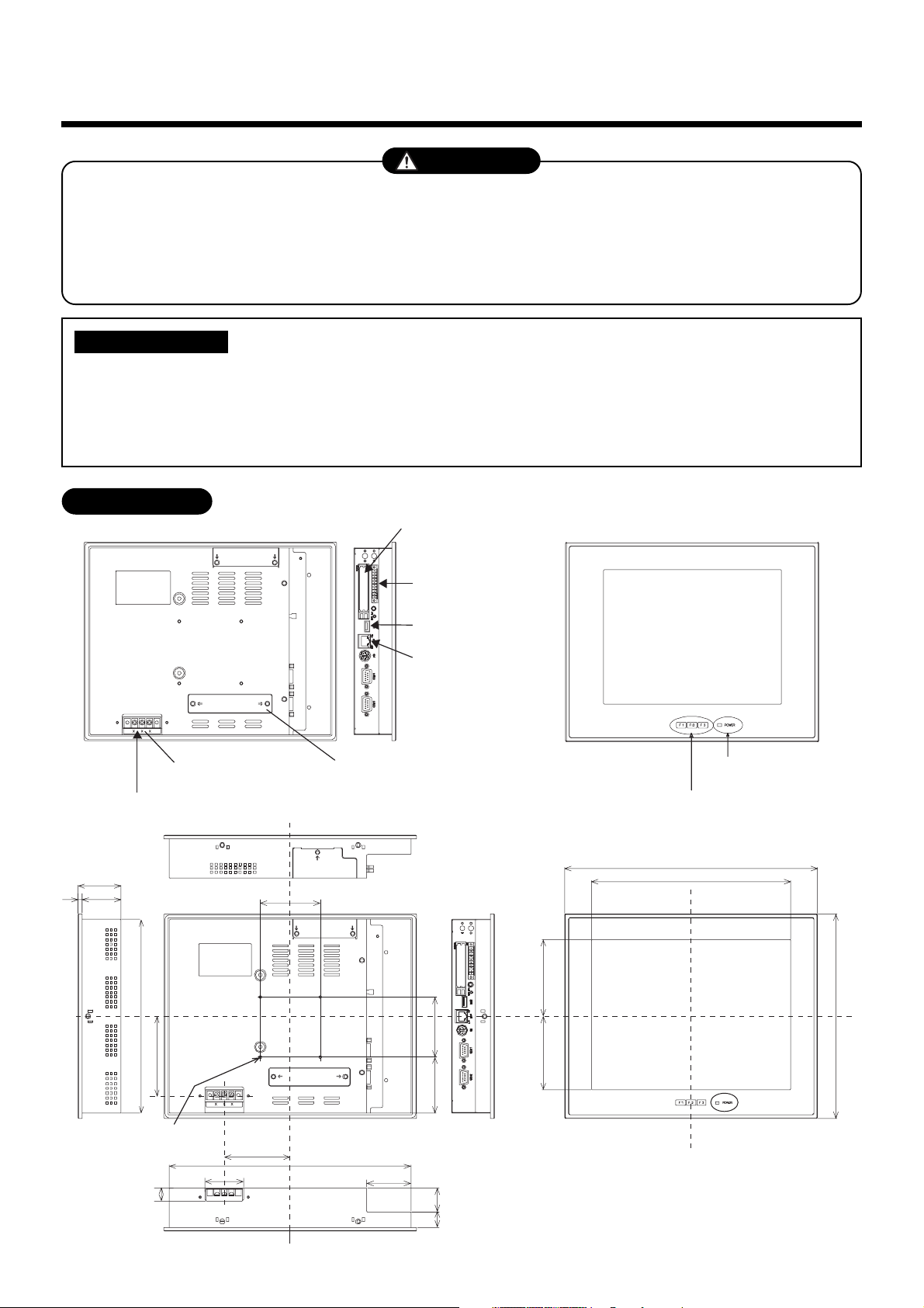
External View
CF (Compact Flash)
card slot (CF card for
data files)
Universal Input/
Output port
Power cable
54
549
242
99.3
Power input
terminal block
75
USB mouse
Ethernet port
Intelligent
Server
PCI expansion unit
connector cover
70 75
POWER LED
Function switch (F1, F2, F3)
316
249
95.7591.75
256
M4 Tap (×4 pcs.)
(depth: 10 mm max.)
16
48
82.5
302
55.5
19 30
unit: mm
3
Page 5
5
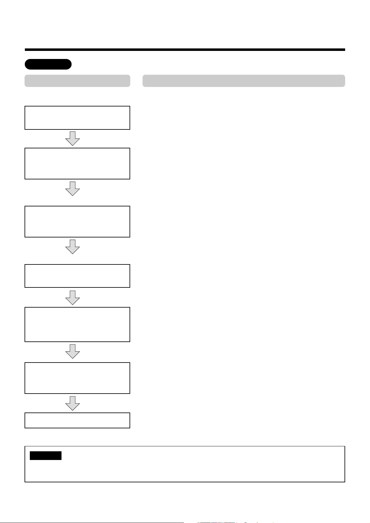
Points for Installation Work
Work flow
Process
(Before work)
Determination of installation
condition
Document creation
(Data input before work)
Enter block/tenant/area names.
Enter schedules for each
R.C. group/indoor name.
(Before installation)
Electrical work
(power/control lines)
Point
• Clarify work categories.
• Determine items of detail control.
• Determine the installation position of the Touch Screen Controller.
• Create a control wiring diagram (see page 9).
• Create an address table for each block, tenant, and area (see
page 10, 11).
• Create a schedule table for each R.C. group/indoor name (see
page 12).
• Enter block/tenant/area names in each address table (see
page 11).
• Enter schedules in each schedule table (see page 12).
• Make connections according to the control wiring diagram (see
page 9).
• Intelligent Server (see APPENDIX page 6)
• TCS-NET Relay Interface (see APPENDIX page 7)
Operation mode/address settings
Trial operation and adjustments
Owner’s manual, delivery
NOTE
For installation, wiring or adjustment of the accessible components for the Touch Screen Controller,
refer to the manual “A04-016”.
• Indoor unit (see APPENDIX page 8-15)
• Checking according to the Before-Trial Operation Check list
(page 10) using the control wiring diagram.
• Operate the indoor unit for each system according to the control
wiring diagram.
Check that there is no incorrect wiring or piping, and then create
a trial operation check list (page 16).
• Give operational explanation in an easy-to-understand manner.
4
Page 6
5
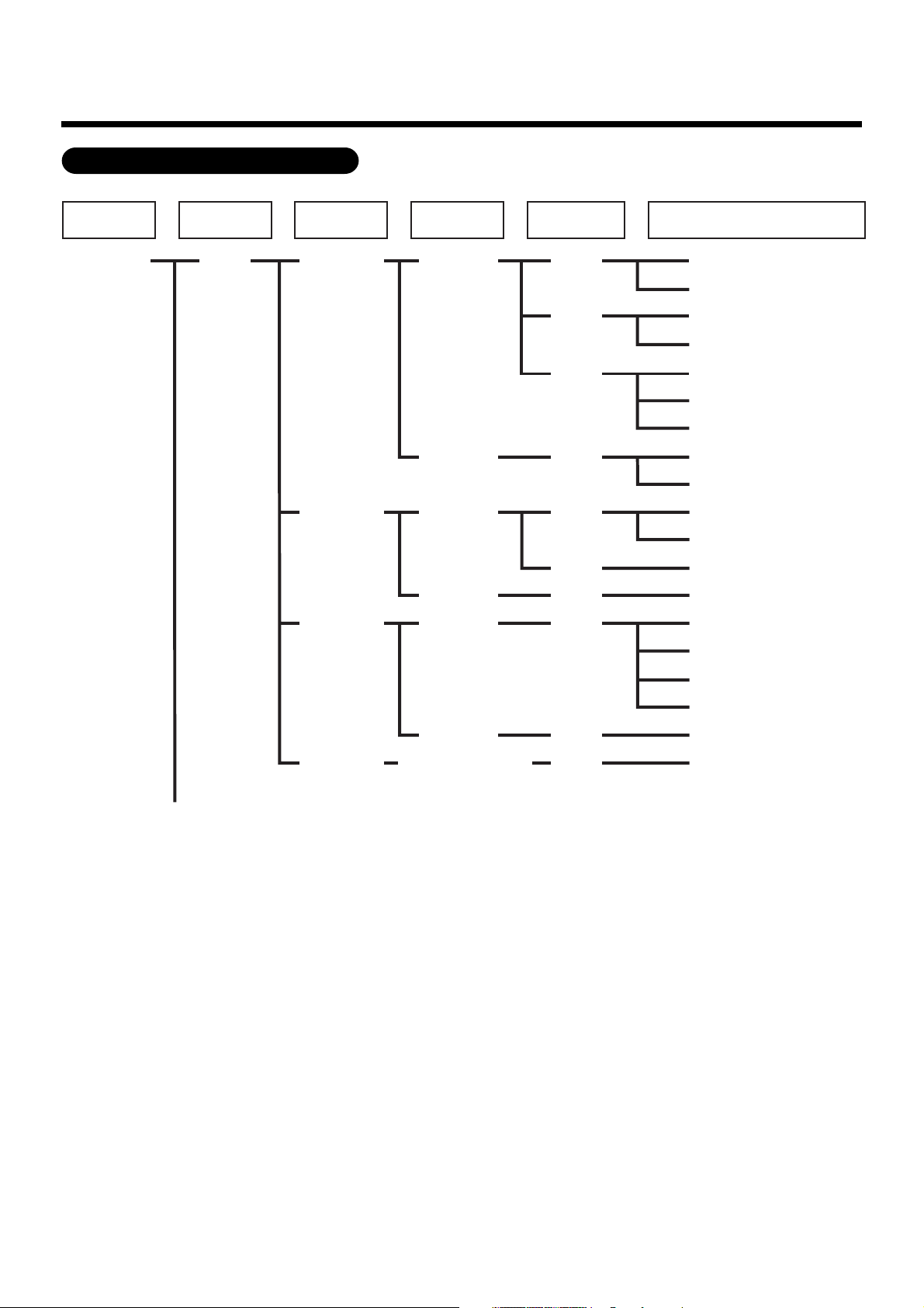
Points for Installation Work (continued)
Management zone categories
All Block Tenant Area
Building A 1-1 (header unit)
1F
Tenant A
Tenant B
Tenant C
Shop A
Office A
Shop B
Office B
Shop C
RC
Group/Unit
101
102
103
104
105
106
107
108
(line address + indoor unit address)
Indoor Unit
1-2 (follower unit)
1-3 (header unit)
1-4 (follower unit)
1-5 (header unit)
1-6 (follower unit)
1-7 (follower unit)
1-8 (header unit)
1-9 (follower unit)
2-1 (header unit)
2-2 (follower unit)
2-3 (header unit)
2-4 (header unit)
2-5 (header unit)
2-6 (follower unit)
Shared
space
Office C
1F outdoor
air conditioner
109
110
2-7 (follower unit)
2-8 (follower unit)
2-9 (follower unit)
3-1 (header unit)
5
Page 7
6
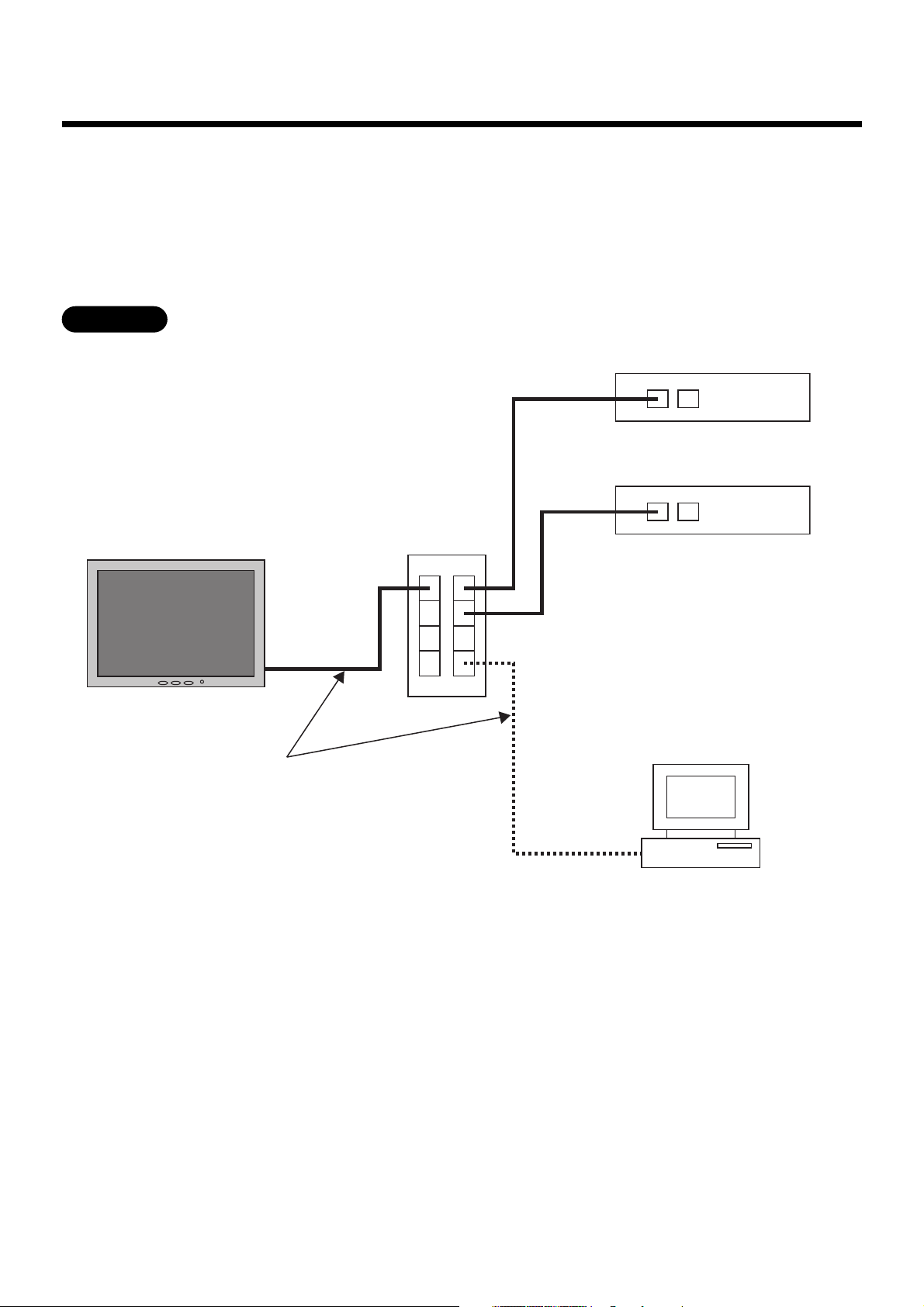
Connect the Touch Screen Controller to Intelligent Servers and to an optional PC for creating monthly
reports using network wires (category 5UTP straight wire), via a Switching HUB (procured on site).
• Connect the Ethernet port of the controller to a port of the HUB with a network wire.
• Connect the Ethernet port 1 of the Intelligent Server to a port of the HUB with a network wire.
• Connect the PC’s Ethernet port to a port of the HUB with a network wire. (Not required if there is not
Connecting the Network wires
need to create reports.)
Ethernet
Touch Screen Controller
Network wires
(category 5UTP straight wire)
Ethernet port
Switching HUB
Ethernet port 1
Ethernet port 2
PC for creating monthly reports
Intelligent Server No.1
Intelligent Server No.2
6
Page 8
7
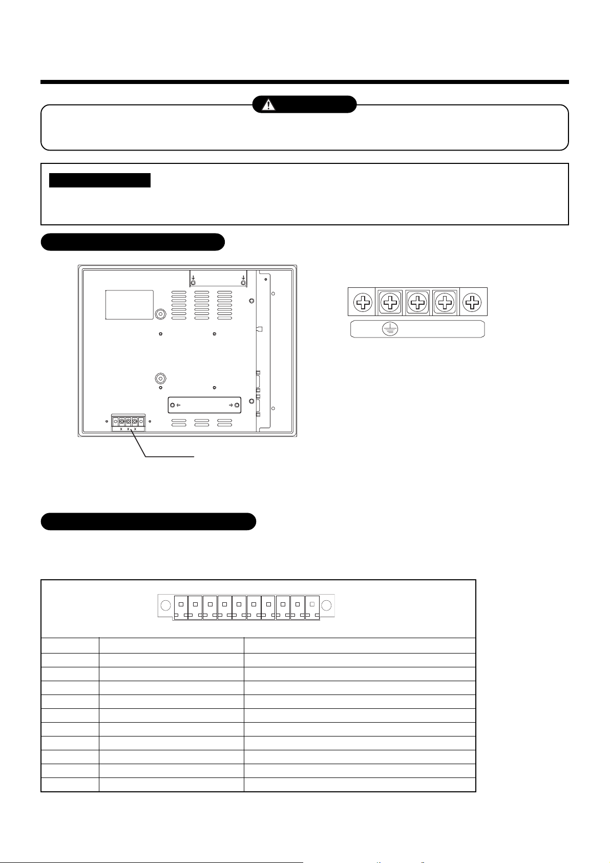
Connecting the Power cable
CAUTION
Connect a proper input AC voltage to the power input terminal block. Failure to do so may cause a
failure.
REQUIREMENT
Power cable is not supplied for the Touch Screen Controller. Prepare a 3-pin power cable conforming
to applicable safety standards. Be sure to connect the earth line each of the power cable securely.
Power Input Terminal Block
■■
■ Power Input Terminal Block
■■
L
N
Rated input voltage: 100 to 240 VAC
Power input terminal block
For M3.5 screws
Terminal pitch: 8.9 mm
Universal Input/Output Port (I/O)
This port is provided with electrically-insulated 3 inputs and 3 outputs for universal use.
■ ■
■ Universal Input/Output port connector
■ ■
10 1
↓ Front (LCD side)
Pin No. Signal name
1
2
3
4
5
6
7
8
9
10
Connector: MC1,5/10-GF-3,5(PHOENIX CONTACT)
Cable connector: MC1,5/10-STF-3,5(PHOENIX CONTACT)
PI_PCOM
PI(0)
PI(1)
PI(2)
P_PO(0)
N_PO(0)
P_PO(1)
N_PO(1)
P_PO(2)
N_PO(2)
Universal input plus common
Universal input 0
Universal input 1
Universal input 2
Universal output 0+
Universal output 0-
Universal output 1+
Universal output 1-
Universal output 2+
Universal output 2-
Remarks
7
Page 9
■■
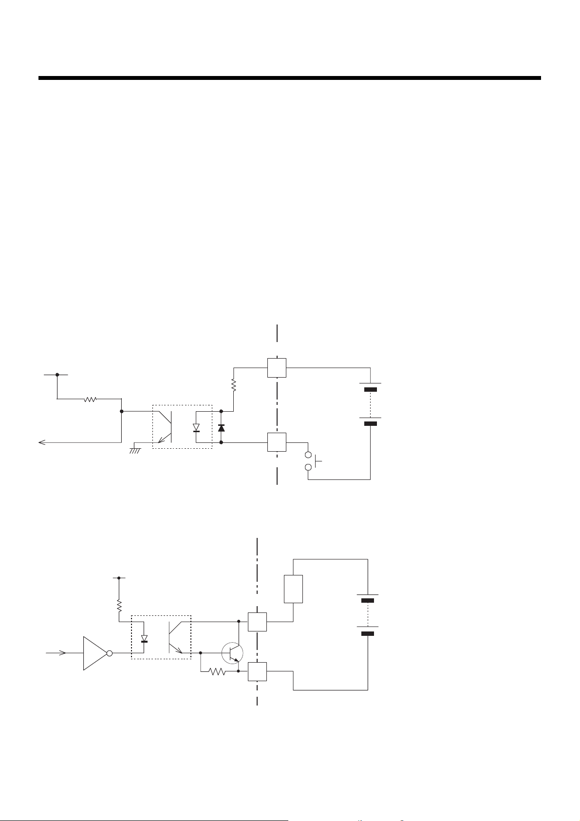
■ Specifications
■■
[Input]
Input system : Current-driven input insulated by photo-coupler
Input resistance : 3 k ohms
Number of input signals : 3
External circuit power voltage : 12 to 24 V DC (±10%)
[Output]
Output system : Open-collector output insulated by photo-coupler
Output rating : 30 V DC, 100 mA maximum
Number of output signals : 3
■■
■ External Input/Output circuit
■■
(1) Input circuit
PI_PCOM
10 k ohm
(2) Output circuit
330 ohm
PC357
3 k ohm
1/2 W
P_PO(0) - P_PO(2)
2SD780A
PI(0) - PI(2)
Input/Output
connector
(External circuit)
load
External power supply
(12 V - 24 V DC)
Input
contact
External power supply
(Max. 30 V DC)
4.7 k ohm
N_PO(0) - N_PO(2)
Input/Output
connector
8
Page 10
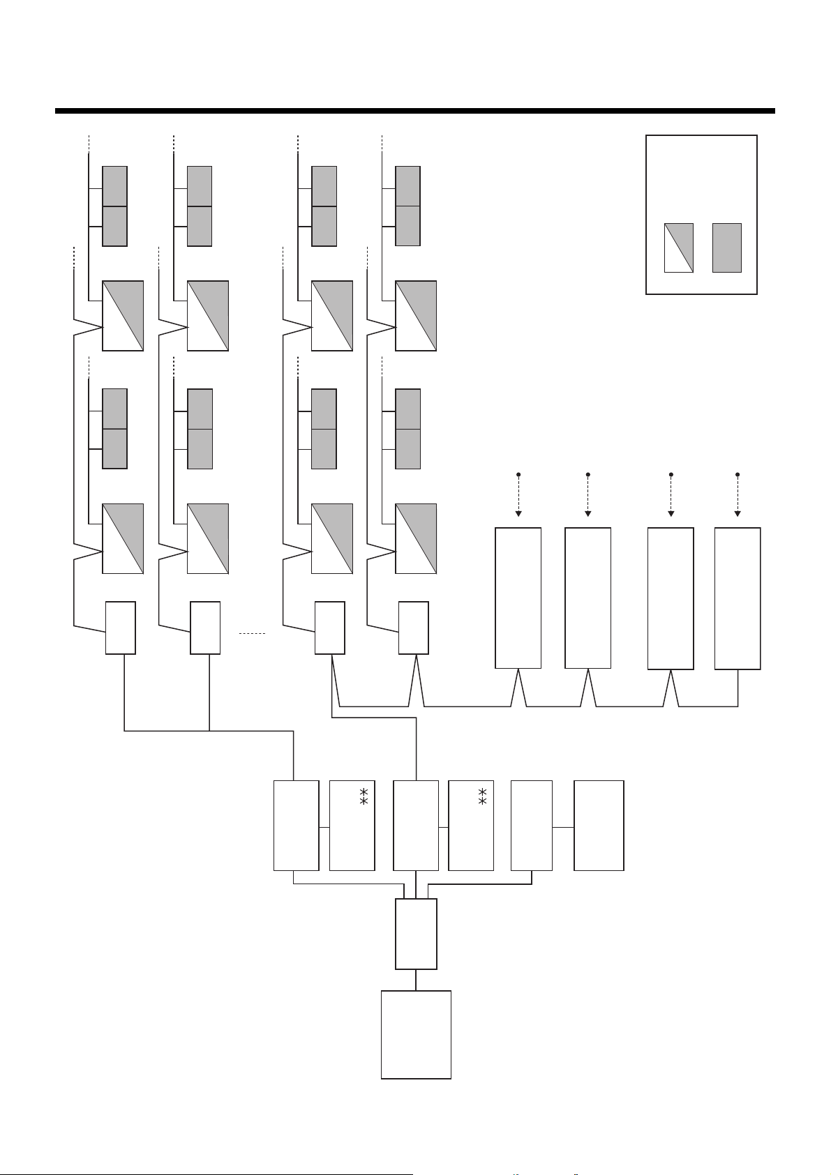
Control Wiring Diagram
8
(Connection example)
U1,U2
U1,U2
U3,U4
U1,U2
U1,U2
U3,U4
U1,U2 U1,U2 U1,U2 U1,U2
U1,U2 U1,U2
U3,U4
U1,U2 U1,U2
U1,U2 U1,U2
U3,U4
U1,U2
U1,U2
8 door-lock control signal inputs
8 fire alarm inputs
Outdoor unit
8 power meter inputs
Indoor unit
8 power meter inputs
Main Bus
16th floor
U3,U4
BMS-
IFLSV1E
15th floor
TCS-NET Relay Interface
U3,U4
BMS-
IFLSV1E
TCS-NET Relay Interface
2nd floor
9th-16th
floor
Server
Intelligent
BMS-LSV2E
U3,U4
BMS-
IFLSV1E
1st floor
TCS-NET Relay Interface
software
Intelligent server
Intelligent
BMS-STCC
U3,U4
BMS-
IFLSV1E
TCS-NET Relay Interface
1st-8th
floor
Server
BMS-LSV2E
HUB
Switching
software
BMS-STCC
Intelligent server
BMS-IFDD01E
Relay Interface
Digital Input/Output
PC for creating
monthly reports
Relay Interface
Digital Input/Output
BMS-IFDD01E
Printer
Energy Monitoring
BMS-IFWH3E
Relay Interface
Relay Interface
Energy Monitoring
BMS-IFWH3E
Touch Screen
Controller
9
Page 11
Air conditioner Address Table
9
and Before-Trial Operation Check list: ( )
No.
Fire alarm
No.
Key input
and Input/Output data
Power
Device Energy Monitoring
Display name
meter No.
Area
name
name
Tenant
Block
name
Address Information
Refrigerant line address
Indoor unit address
Group address
Intelligent Server address
TCS-NET relay I/F address
Header
Indoor unit
R.C. group/
Air Conditioner List
Outdoor unit
Outdoor
• Building name:
unit
model name
unit
name
model name
refrigerant
1
2
3
4
5
6
7
8
9
10
11
12
15
16
17
18
19
20
10
Page 12
Air conditioner Address Table and Before-Trial
Operation Check list (Example)
1
1
1
1
1
1
1
1
1
1
1
1
1
1
1
1
No.
Fire alarm
1
No.
Key input
and Input/Output data
Power
Device Energy Monitoring
Display name
meter No.
Area
name
name
Tenant
1
1
1
Shop A
Shop A
Tenant A
Tenant A
1
1
1
1
Shop A
Shop A
Tenant A
Tenant A
1
1
1
1
Shop A
Shop B
Tenant A
Tenant B
1
1
1
1
Shop C
Shop D
Tenant B
Tenant B
1
1
1
2
Shop E
Shop F
Tenant B
Tenant C
1
1
2
2
Shop F
Shop G
Tenant C
Tenant C
1
1
2
2
Office
Office A
Tenant C
1
2
Office
Office A
1
1
1
2
2
Meeting room
Meeting room
Office A
Office A
2
2
2
2
3
3
A
B
Shared space
2
2
3
Shop H
Tenant D
Block
Address Information
Refrigerant line address
Indoor unit address
Group address
Intelligent Server address
TCS-NET relay I/F address
Header
Indoor unit
R.C. group/
1F
name
1
1
1
unit
model name
MMU-AP0091H
unit
name
PAC-B1 • IF-1
1F
1F
1F
2
2
2
2
3
4
0
0
0
MMU-AP0091H
MMU-AP0091H
MMU-AP0091H
PAC-B1 • IF-1
PAC-B1 • IF-1
PAC-B1 • IF-1
1F
1F
1F
1
1
2
0
0
5
6
7
1
0
1
1
MMK-AP0091H
MMU-AP0091H
PAC-B1 • IF-1
MMK-AP0091H
PAC-B1 • IF-2
PAC-B1 • IF-3
1F
1F
1F
0
0
0
8
9
1
1
1
1
MMK-AP0091H
MMK-AP0091H
MMK-AP0091H
PAC-B1 • IF-4
PAC-B1 • IF-5
PAC-B1 • IF-1
1F
1F
1F
1
1
0
0
0
2
3
4
2
1
1
1
MMK-AP0091H
MMK-AP0091H
MMK-AP0091H
PAC-M • IF-2
PAC-M • IF-3
PAC-M • IF-4
1F
1F
1F
0
0
0
5
6
7
1
1
1
MMK-AP0091H
MMK-AP0091H
MMK-AP0091H
PAC-M • IF-5
PAC-M • IF-6
PAC-M • IF-7
1F
2F
2F
1
1
0
1
2
8
1
2
3
1
1
0
MMK-AP0091H
MMK-AP0091H
MMK-AP0091H
PAC-M • IF-8
PAC-S • 2F-1
2F
0
3
1
MMK-AP0091H
PAC-S • 2F-2
Air Conditioner List
model name
Outdoor unit
Outdoor
refrigerant
• Building name:
1
MMY-AP1401HT8
PAC-B1
2
3
4
5
6
7
8
9
10
11
MMY-AP1401HT8
PAC-M
12
13
14
15
16
17
MMY-AP1401HT8
PAC-S
18
19
20
11
Page 13

Schedule Table for
10
Each
R.C. group/indoor Name
:
:
:
:
:
:
:
:
PAC-B1, 1F-6
Night-duty room
B1
Run
Stop
8:00
9:30
Monday to Saturday
Run
Stop
Stop
10:00
Run
Run
16:30
Stop
Stop
22:00
Stop
Stop
23:58
:
:
:
:
:
:
:
:
:
:
PAC-B1, 1F-3 to 1F-5
Warehouse
XX Electric Co., Ltd.
B1
:
:
:
:
:
:
:
:
PAC-B1, 1F-1
Consultation room
XX Dental Clinic
B1
8:00
12:00
13:00
19:00
Monday to Friday
Run
Stop
Stop
8:00
19:00
Monday to Saturday
:
21:00
21:00
:
:
:
:
:
:
:
Schedule Table ( / )
R.C. group/unit name
Area
• Building name:
Tenant
1
Block
Day of the week
2
3
4
5
6
7
8
Schedule Table (Example)
R.C. group/unit name
Area
Tenant
• Building name: XXX Building
Block
1
2
3
Day of the week
4
5
6
7
8
12
Page 14

11
Installation
Touch Screen Controller
Make space for installation and service.
Install the Touch Screen Controller in a wall (standard) or on the dedicated stand (when available on site).
In-wall installation
■■
■Conditions for installation
■■
Space 30 mm or more between the controller and
surrounding objects as the ambient temperature
must satisfy the installation space requirements.
Panel
30 mm or more (top)
30 mm or more (bottom)
30 mm or more (rear)
Top view
30 mm or more (side)
Interface side
Panel
■■
■Attaching Fixture
■■
■Panel cut size
+1
303
-0
R1 or less
+1
-0
243
REQUIREMENT
Use a panel
(procured on site) of
thickness 1.6-1.7 mm.
Panel thickness: 1.6 -1.7 mm
[mm]
1. Insert the controller from outside of the panel.
2. Insert the fixtures from inside of the panel.
Touch Screen
Controller
Panel
Fixture
Bottom view
For reference
Display stand (not supplied with the controller)
Use the CONTEC stand (model: IPC-SND-03).
For details of the stand, visit the CONTEC web site.
Europe: http://www.contec-europe.com/
China: http://www.contec.sh.cn/
REQUIREMENT
• Check that the installation dimensions on the rear of the
Touch Screen Controller equal the installation
dimensions of the CONTEC stand.
• Use the screws supplied with the stand to install the
controller.
13
Tightening screws excessively
may cause the screws to break.
Optimum tightening torque for
good waterproofing effect is
0.6N/m.
75 mm
75 mm
The angle adjustment lock screw.
(Loosen the screw and adjust angle.)
Page 15

12
Trial Operation
Item Description
Preparation
Entering names
Checks before trial
operation (control
wiring)
Trial operation
startup
Preparation of necessary
documents
Entry of setting conditions
Checking installation work
Checking control wiring
using the before-trial
operation check list.
Checking block/tenant/area
names
Checking schedules
Power on
Initial screen
System initialization
Check point
● Meeting with the customer on setting information
Creation of control wiring system diagram
Creation of air conditioner address table
Creation of schedule table for each R.C. group/indoor name
● Create a setting file including setting data.
● Set the setting data in the Touch Screen Controller by
overwriting (copy) the data on its CF (Compact Flash) card.
● Power supply wiring
● Control wiring
● Grounding of units
● Check control wiring specifications and wire sizes.
● Check block/tenant/area names using the air conditioner
address table.
● Check schedules using the schedule table for each R.C.
group/indoor name.
● Turn on the Touch Screen Controller with the Intelligent
Server and the relay interface turned on.
● The controller software starts automatically, and the total
building control screen appears.
● Select “System Initialize” from the option to initialize the
system.
When “System Initialize” is selected, a message “Will you
re-cold start all intelligent server?” appears. Select “Yes”.
The setting file is transmitted from the Intelligent Server to
the relay interface.
The L1 or L2 LED of the Intelligent Server blinks during the
startup process. When the startup processing ends
successfully, the L1 and L2 LEDs turn off. If the startup
processing fails, the L1 LED lights up. Retry “System
Initialize” from the Touch Screen Controller in this case. Or
select “TPC-CON” on the hidden Windows task bar at the
bottom of the LCD screen. You can see a message on the
screen during the system reset. The “Access Start”
message appears at the end of several message lines. It
takes several minutes for system initialization.
Trial operation
Checking communication
status (referring to the
control wiring system
diagram)
Checking operation status
using the before-trial
operation check list.
● Select air conditioning screen after System Initialize to check
communication status and connection of air conditioners.
Check that there is no orange frame on the command button
of the air conditioner, which indicates a communication
error. If an orange frame is present, check power on (or off),
control line wiring, and address setting of the air conditioner.
● Check operation status for each block, tenant, area, and
R.C. group/indoor name.
- ON/OFF
- Operation mode
- Set temperatures
Check all indoor units whether controls can be changed from
the Touch Screen Controller to the R.C. group/indoor, and
whether the setting changed by the remote controller is
reflected on the Touch Screen Controller on both the Touch
Screen Controller side and the on-site remote controller side.
14
Page 16

12
Trial Operation (continued)
Trial Operation Check list
Tenant Block
Area
Set temperature
indoor
R.C. group/
E
E
Block
Tenant
Check list
Area
R.C. group/
Block
indoor
E
E
E
B
E
E
E
E
E
E
E
B
B
E
E
E
E
E
E
E
E
E
E
E
E
E
E
E
E
E
E
E
E
E
E
E
E
E
E
E
E
E
E
E
E
E
E
E
E
E
E
E
E
E
E
E
E
E
E
E
E
E
E
E
E
E
E
E
E
E
E
E
E
E
E
E
E
E
E
E
E
• D .............. COOL
• E ... COOL/HEAT
• F ................ HEAT
B
B
B
B
B
B
B
B
B
B
B
B
B
B
B
B
B
Tenant
ON/OFF Operation mode
Area
indoor
R.C. group/
Display name
Block name Tenant name Area name
B
B
B
B
B
B
B
B
B
B
B
B
B
B
B
B
B
B
B
B
B
B
B
B
B
B
B
B
B
B
B
B
B
B
B
B
B
B
B
B
B
B
B
B
B
B
B
B
B
B
B
B
B
B
B
B
B
B
B
B
• A ............. O N
• B .... ON/OFF
• C ........... OF F
No.
R.C. group/indoor
• Building name:
1
2
3
4
5
6
7
8
9
10
11
12
13
14
15
16
17
18
19
20
15
Page 17

Trial Operation Check list (Example)
OK
OK
OK
OK
OK
OK
OK
OK
OK
E
E
E
E
B
B
OK
OK
OK
OK
E
E
E
E
B
B
Block
Tenant
Area
R.C. group/
Block
Tenant
Check list
Area
R.C. group/
Block
Tenant
indoor
indoor
OK
OK
OK
E
E
E
E
B
B
OK
OK
OK
E
E
E
E
B
B
OK
OK
OK
E
E
E
E
B
B
OK
OK
OK
E
E
E
E
B
B
OK
OK
OK
E
E
E
E
B
B
OK
OK
OK
OK
E
E
E
E
B
B
OK
OK
OK
OK
E
E
E
E
B
B
OK
OK
OK
OK
E
E
E
E
B
B
OK
OK
OK
OK
E
E
E
E
B
B
OK
OK
OK
OK
E
E
E
E
B
B
OK
OK
OK
OK
E
E
E
E
B
B
OK
OK
OK
OK
E
E
E
E
B
B
OK
OK
OK
OK
E
E
E
E
B
B
OK
OK
OK
OK
E
E
E
E
B
B
OK
OK
OK
OK
E
E
E
E
B
B
OK
OK
OK
OK
E
E
E
E
B
B
OK
OK
OK
OK
E
E
E
E
B
B
OK
OK
OK
OK
E
E
E
E
B
B
• D .............. COOL
• E ... COOL/HEAT
• F ................ HEAT
ON/OFF Operation mode Set temperature
Display name
Block name Tenant name Area name
No.
R.C. group/indoor
• Building name:
B
Area
B
indoor
R.C. group/
PAC-B1, 1F-1
1
B
B
B
B
B
B
PAC-B1, 1F-2
PAC-B1, 1F-3
PAC-B1, 1F-4
2
3
4
B
B
B
B
B
B
PAC-B1, 1F-5
PAC-B1, 1F-6
PAC-B1, 1F-7
5
6
7
B
B
B
B
B
B
PAC-B1, 1F-8
8
PAC-M-1
PAC-B1, 1F-9
9
10
B
B
B
B
PAC-M-2
PAC-M-3
11
12
B
B
B
B
PAC-M-4
PAC-M-5
13
14
B
B
B
B
PAC-M-6
PAC-M-7
15
16
B
B
B
B
PAC-S-1
PAC-M-8
17
18
B
B
B
B
PAC-S-2
PAC-S-3
19
20
• A ............. O N
• B .... ON/OFF
• C ........... OF F
16
Page 18

13
Trouble shooting
Regarding faults that may occur after installation, trial operation, and adjustments of Air conditioning
control system and their remedies:
Faults of air conditioner
• The Touch Screen Controller displays an error code and description that are the same as those
displayed on the remote controller.
• Check the faulty air conditioner according to the check points of each error code of the air conditioner.
Faults of air conditioning control system
Faults detected by Touch Screen Controller
• Touch Screen Controller displays an error code and description. (Not displayed on the remote
controller)
• Take remedial action according to the description and possible causes of each error code in the table
below.
Error
code
S00
S01
S06
S07
Description
Intelligent server
communication
error.
Communication
error between
Indoor and BMS.
BMS-IFWH
communication
error.
BMS-IFDD
communication
error.
Possible causes
Intelligent Server is not powered on.
Switching HUB is not powered on.
Improper connection of network cable.
Malfunction of Intelligent Server.
Air conditioner is not powered on.
Improper TCC-LINK connection.
Malfunction of Intelligent Server.
Malfunction of Relay Interface.
Energy Monitoring Relay Interface is not powered
on.
Improper RS-485 cable connection.
Malfunction of Energy Monitoring Relay Interface.
Malfunction of Intelligent Server.
Digital I/O Relay Interface is not powered on.
Improper RS-485 cable connection.
Malfunction of Digital I/O Relay Interface.
Malfunction of Intelligent Server.
Remedy
Remove the cause and then
power on the Intelligent Server,
Switching HUB, and Touch
Screen Controller.
Remove the cause and then
power on the air conditioner,
Intelligent Server, and Relay
Interface.
Remove the cause and then
power on the Energy Monitoring
Relay Interface and Intelligent
Server.
Remove the cause and then
power on the Digital I/O Relay
Interface and Intelligent Server.
17
Page 19

Other faults
No.
1
2
3
4
5
6
Description
Nothing is displayed on
the Touch Screen
Controller screen.
Remote controller does
not work. (Central
control in progress)
Remote controller does
not work. (Operation
switchover control in
progress)
Scheduled operation of
air conditioners is
disabled.
Air conditioner stops
(out of control).
Power distribution
result is incorrect.
Possible causes
Touch Screen Controller is not powered on.
Backlight turns off automatically due to no
touch-screen operation for 10 minutes.
Malfunction of Touch Screen Controller.
Air Conditioning Control System
malfunctioned or stopped after local
prohibition is set by the system.
Operation mode range selection is set by
the Air Conditioning Control System.
Air Conditioning Control System is not
working.
Scheduled operation is not set or nonoperation date/special day setting is not
updated. (The setting must be updated
every year.)
Scheduled operation is not set correctly.
Incorrect input of door-lock signal.
Improper connection between power meter
and BMS-IFWH3E
Charging schedule is not set correctly.
Non-operation date/special day setting is
not updated. (The setting must be updated
every year.)
Remedy
Power on the Touch Screen Controller.
Touch the Touch Screen
Controller screen.
Power off and on the Touch
Screen Controller.
Power off and on the air
conditioner.
Check the operation mode range
selection setting, and correct it if
wrong.
Power on the equipment of the
system.
Perform setting for scheduled
operation.
Check the scheduled operation
setting, and correct it if wrong.
Correct the signal connection.
Correct the connection.
Check the charging schedule
setting, and correct it if wrong.
Fault judgment by Intelligent Server
No.
1
An LED other than
“RN” LED at the upper
left is lighting or
flashing after 10
minutes passed from
power on of Intelligent
Server.
Indication
No Relay Interface is powered on.
Communication with any Relay Interface
fails due to improper RS-485 connection or
disconnection of connector.
Malfunction of Intelligent Server.
Faults of Relay Interface
No.
1
2
LED2 (green) does not
light.(RS-485
communication error)
LED3 (orange) does
not light.
Indication
Intelligent Server is not powered on.
Improper RS-485 connection or
disconnection of connector.
Improper connection of TCC-LINK main bus
due to disconnection or lack of terminating
resistors, etc.
Possible causes
Possible causes
Remedy
Check whether every Relay
Interface is powered on (shown by
LED1 lighting red), and turn on
them if powered off.
Correct the connection.
Power off and on the Intelligent
Server.
Remedy
Power on the Intelligent Server.
Correct the connection.
Correct the connection.
18
Page 20

14
Control Specifications
Basic Functions
Function Item
Operation
Setting
Indication
Schedule
Fire alarm input
Recording
●ON/OFF
Operation mode (cooling/
heating/fan only)
Air flow (High/Mid/Low)
Temperature (18-29 °C)
Operation enable/disable
●ON
●OFF
●Failures/errors
●Details of failure
●Operation under master
schedule
●Operation under selective
schedule
●Leaving-ON prevention
setting
●Extra-charging schedule
setting
●Fire alarm interlocking
control
●Monthly data file output
Description
Master operation and setting of:
- Entire building
- Each block *
- Each tenant *
- Each area *
- Each R.C. group/indoor *
Displays in green on the screen for each R.C. group/indoor.
Displays in red on the screen for each R.C. group/indoor.
Displays in orange on the screen for each R.C. group/indoor.
Displays with inspection codes and characters.
●Basic-week pattern, specific-day pattern, and monthly setting of
selected R.C. group/indoor can be set. Annual schedule is fixed
upon completion of all settings, which enables auto operation.
●
Performs weekly operation/stop of selected
automatically. Selective schedule is effective only for date/time
modified temporarily.
●Schedule setting for 10 patterns/day (ON/OFF total 20 patterns/
day) is available.
●Schedule setting for specified day of the week is available for each
R.C. group/indoor.
●This setting is available for specified day of the week by using OFF
setting for each R.C. group/indoor.
●
Extra-charging time zone can be set for specified day of the week
for each
operation setting.
●Stops operation of all air conditioners at a time upon receiving a fire
alarm signal.
●Indicates an occurrence of fire.
●Outputs air conditioner operating hours and the number of ON/OFF
times to a file for each R.C. group/indoor.
●Outputs air conditioner operating hours within the extra-charging
time zone to a file for each R.C. group/indoor.
●Outputs failure information to a file for each R.C. group/indoor.
1
2
3
4
R.C. group/indoor
R.C. group/indoor
independently from the scheduled
*1 Block: One floor zone of building
*2 Tenant: Shops and shared zone
3
*
Area: Tenant shop/office zone
*4 R.C. group/indoor: Indoor unit system controlled by single remote controller (group)
Specifications
Item Description
Power supply
Power consumption
Operating condition temperature, Humidity
Dimensions
Mass
100 - 240 V, AC 50/60 Hz
50 VA
0 - 40 °C, 20 - 85%RH
316 (W) x 256 (H) x 54 ( D) mm
Approx. 3.5 kg
19
Page 21

APPENDIX
APPENDIX
Touch Screen Controller System Configuration ................................................................................ 1
Wiring Specifications ........................................................................................................................ 3
Touch Screen Controller Connection Diagram ................................................................................. 4
Address setting Flow ........................................................................................................................ 5
Address Setting for Component Device ........................................................................................... 6
Intelligent Server ...................................................................................................................... 6
TCS-NET Relay Interface address setting ............................................................................. 7
Air conditioner address setting (example) ............................................................................... 8
Address Setting for Air Conditioner .................................................................................................. 9
Setting for VRF system ........................................................................................................... 9
Manual setting from wired remote controller .......................................................................... 10
Line (system) address setting ............................................................................................... 12
Power reset ............................................................................................................................ 12
Indoor unit address check ..................................................................................................... 13
Trial operation ........................................................................................................................ 13
Setup of relay connector and terminator ............................................................................... 14
Page 22

APPENDIX
Touch Screen Controller System Configuration
Ethernet
InteIligent Server
(BMS-LSV2E)
Touch Screen Controller
(BMS-TP0640/5120)
Intelligent server Software
(BMS-STCC01E)
(*) A Switching HUB is required when using
two or more Intelligent Servers or when
connecting to a customer PC.
Switching HUB
Customer PC
Compact
Flash
RS-485
(BMS-IFDD01E)
TCS-NET
Relay I/F
(BMS-IFLSV1E)
TCS-NET
Relay I/F
(BMS-IFLSV1E)
MAX 8
Energy
Monitoring
Relay I/F
(BMS-IFWH3E)
Energy
Monitoring
Relay I/F
(BMS-IFWH3E)
MAX 4
Digital I/O
Relay I/F
(BMS-IFDD01E)
Digital I/O
Relay I/F
MAX 4
TCC-LINK Main Bus
Max. 64 air conditioners
per relay I/F
TCC-LINK Main Bus
Max. 64 air conditioners
per relay I/F
Power meter 1
(with pulse generator)
Power meter 8
(with pulse generator)
Power meter 1
(with pulse generator)
Power meter 8
(with pulse generator)
Input contact 1
Input contact 8
Load 1
Load 4
Input contact 1
Input contact 8
Load 1
Load 4
Max. 8 power
meters per relay I/F
Max. 8 power
meters per relay I/F
Max. 8 input
contacts per
relay I/F
Max. 4 loads
per relay I/F
Max. 8 input
contacts per
relay I/F
Max. 4 loads per
relay I/F
Max. 512 indoor
units (64 units x 8)
per Intelligent
Server
Max. 32 (8 x 4)
power meter
Max. 32 (8 x 4)
digital inputs
Max. 16 (4 x 4)
digital outputs
-1-
Page 23

APPENDIX
System Configuration Table
Touch Screen Controller
Air conditioning control
Power distribution
Indoor units connected
Function
Intelligent Server
Intelligent Server Software
TCS-NET Relay I/F
Component
Energy Monitoring Relay I/F
Digital I/O Relay I/F
Switching HUB
Network wire
PC
Power meter
*1:The number of network wires and the number of switching HUB port vary with the number of Intelligent Server connected.
*2:100 BASE-T compliant is required in using 5 or more server, or 2 or more controllers.
*3:The number of power meters vary with power meter specifications.
BMS-LSV2E
BMS-STCC01E
BMS-IFLSV1E
BMS-IFWH3E
BMS-IFDD01E
Procured on site
Procured on site
Procured on site
Procured on site
BMS-TP0640ACE BMS-TP0640PWE BMS-TP5120ACE BMS-TP5120PWE
– ±
Max. 64 units
Max. 8 units
– Max. 4 units
Max. 4 units
Remarks
Comply with 10BASE-T
Number of ports: As required
1
Category 5 UTP straight wire
*
OS: Windows 2000 or later, Excel 2000 or later
3
Pulse output type pulse: 1 kw-hr/pulse or 10 kw-hr/pulse
*
Pulse duration: 50 - 1000 ms
Output terminal: ON/OFF contactor
...
(±
available –
±
1 unit
1 unit
...
not available)
±
– ±
Max. 512 units
Max. 4 units
1 unit per Intelligent Server
(max. 4 units in total)
Up to 8 units per Intelligent Server
(max. 32 units in total)
– Max. 4 units
Max. 4 units
2
*
-2-
Page 24

Wiring Specifications
Power supply specifications
APPENDIX
Device Input voltage
Touch Screen Controller
Intelligent Server
TCS-NET Relay Interface
Energy Monitoring Relay Interface
Digital I/O Relay Interface
100 - 240 V, AC 50/60 Hz
85 - 132 V, AC 50/60 Hz
180 - 264 V, AC 50/60 Hz
220 - 240 V, AC 50/60 Hz
Power
consumption
50 VA
30 VA
2.4 W
2.8 W
6.5 W
Power cable
wire size
0.75 mm
2
Remarks
Procure on site
Communication wiring specifications
Inter-device connection Control wiring
specifications
Intelligent Server ↔ TCS-NET
Relay Interface
Intelligent Server ↔ Energy
Monitoring Relay Interface
Intelligent Server ↔ Digital I/O
Relay Interface
TCS-NET Relay Interface ↔ Air
conditioner
Energy Monitoring Relay Interface
↔ Power Meter
Digital I/O Relay Interface ↔ Digital
Input/Output
*1: Use the D-sub (9 pin) wire supplied with the Intelligent Server software. If its length is short, use a shield wire.
*2: Total length per TCS-NET Relay Interface
D-sub (9-pin) wire *
(If length is short) Use a
shield wire
Shield wire
Shield wire
Shield wire
Shield wire
1
Number of
cores
4
2
2
2
2
2
2
2
Wire size
2
(mm
)
2
1.25 mm
2
1.25 mm
2
1.25 mm
2
1.25 mm
2
2.0 mm
2
0.3 mm
2
0.3 mm
Length
(m)
Max. 500
Max. 500
Max. 500
Max.1000*
Max.2000*
Max. 100
Max. 100
Polarity
With polarity
With polarity
With polarity
2
No polarity
2
No polarity
No polarity
With polarity
Remarks
Supplied with
Intelligent
Server software
Procure on site
Procure on site
Procure on site
Procure on site
Procure on site
Procure on site
Procure on site
Ethernet wire specifications
When Switching HUB is not used
Inter-device connection Control wiring
specifications
Touch Screen Controller ↔
Intelligent Server
Ethernet (cross)
Category 5 UTP cross wire
When Switching HUB is used
Inter-device connection Control wiring
specifications
Touch Screen Controller ↔
Switching HUB
Switching HUB ↔ Intelligent
Server
Ethernet (straight)
Category 5 UTP straight wire
Ethernet (straight)
Category 5 UTP straight wire
Number of
cores
8
Number of
cores
8
8
Wire size
2
(mm
)
–
Wire size
2
(mm
)
–
–
Length
(m)
Max. 100
Length
(m)
Max. 100
Max. 100
Polarity
–
Polarity
–
–
Remarks
Procure on site
Remarks
Procure on site
Procure on site
-3-
Page 25

APPENDIX
Touch Screen Controller Connection Diagram
SW6
ON
TCC-LINK
TERMINATOR
12
SW5
RS-485
ON
TERMINATOR
1
2
RS-485
TCS-NET RELAY
INTERFACE
SW6
ON
TCC-LINK
TERMINATOR
12
SW5
ON
RS-485
TERMINATOR
1
2
RS-485
TCS-NET RELAY
INTERFACE
ADDRESS
ADDRESS
U4U3
U2U1
Outdoor
unit
SW1
8
U2U1
U2U1
Indoor unit
Remote
controller
U4U3
U2U1
Outdoor
unit
SW1
1
U2U1
Remote
controller
U2U1
Indoor unit
Outdoor
unit
Indoor unit
Remote
controller
Outdoor
unit
Indoor unit
Remote
controller
U4U3
U2U1
U2U1
U4U3
U2U1
U2U1
Yellow
Brown
B
A
Red
Crimp 3 wires with
a closed end wire joint.
Orange
A
B
Red/Orange
Brown/Yellow
Power supply
Power supplyPower supplyPower supplyPower supplyPower supply
TCC-LINK
TCC-LINK
FG
U1U2
ABLNLNLNLNLN LN
FG
U1U2
AB
U4U3
Indoor unit
U4U3
Indoor unit
Central remote
controller
Central remote
controller
INTELLIGENT SERVER
(BMS-LSV2E)
TOUCH SCREEN CONTROLLER
(BMS-TP0640/5120)
SW1
4
ADDRESS
DIGITAL I/O
INTERFACE
(BMS-IFDD01E)
SW1
1
ADDRESS
DIGITAL I/O
INTERFACE
(BMS-IFDD01E)
SW1
4
ADDRESS
DI 1
DI 2
DI 3
DI 4
DI 5
DI 6
DI 7
DI 8
DI 1
DI 2
DI 3
DI 4
DI 5
DI 6
DI 7
DI 8
DI 1
DI 2
DI 3
DI 4
DI 5
DI 6
DI 7
DI 8
Input contact 1
Input contact 2
Input contact 3
Input contact 4
Input contact 5
Input contact 6
Input contact 7
Input contact 8
RS-485
DO1
DO2
DO3
DO4
GND
+12V
RS-485
DO1
DO2
DO3
DO4
GND
+12V
Load 1
Load 2
Load 3
Load 4
Input contact 1
Input contact 2
Input contact 3
Input contact 4
Input contact 5
Input contact 6
Input contact 7
Input contact 8
Load 1
Load 2
Load 3
Load 4
Power meter 1
Power meter 2
Power meter 3
Power meter 4
Power meter 5
Power meter 6
Power meter 7
Power meter 8
ENERGY
MONITORING
INTERFACE
SW1
1
ADDRESS
ENERGY
MONITORING
INTERFACE
-4-
DI 1
DI 2
DI 3
DI 4
DI 5
DI 6
DI 7
DI 8
BA BA BA
RS-485
Power meter 1
Power meter 2
Power meter 3
Power meter 4
Power meter 5
Power meter 6
Power meter 7
Power meter 8
BA
RS-485
Page 26

Address Setting Flow
APPENDIX
Setting flow
Power on
Manual address setting
Line address setting
Power reset
Indoor unit address check
Trial operation (R.C. group/indoor name)
Contents
Indoor units/Outdoor units
Setting from main wired remote controller
(Line/Group/Indoor address setting)
Dip Switch setting on outdoor interface
P.C.board
Power reset to activate line address
7 segment display on outdoor interface
P.C.board check line/indoor address on
remote controller
Test operation in each R.C. group/
indoor name one by one
Reference page.
page 10
page 12
page 12
page 13
page 13
Setup of relay connector and SW30-2
Central controller exsit ?
Central control device setting
TCS-NET control system setting
Intelligent server
TCS-NET relay I/F
Energy monitoring relay I/F
Digital I/O relay I/F
Central control wiring and terminator
setting
When central remote controller is
connected, setup the central control
address with following the installation
manual included in the central control
devices.
Switch setting
CF (Compact Flash) card mounting
page 14
Trial operation for Touch panel controller Operation from touch screen controller
-5-
Page 27

APPENDIX
Address Setting for Component Device
Intelligent Server
Installing CF (Compact Flash) card
WARNING
• Do not insert or remove the CF (Compact Flash) card during power on of the Intelligent Server.
Doing so may cause a failure.
• If the CF (Compact Flash) card is not inserted properly, the Intelligent Server does not work.
Insert the attached CF (Compact Flash) card fully into the CF (Compact Flash) card slot on the side of
the Intelligent Server.
CF (Compact Flash) card
CF (Compact Flash) card slot
RS-485 operation mode setting
CAUTION
If the RS-485 mode set switch is set incorrectly, the Intelligent Server will not work.
The RS-485 mode set switch is provided on the bottom board of the Intelligent Server.
Set the switch as follows:
1234
OFF ON ON OFF
LED indicator side
RS-485 mode set
switch
1234
1
ON
A terminator resistor is connected between TX(+) and TX(-).
OFF
No terminator resistor is connected between TX(+) and TX(-).
2
ON
A terminator resistor is connected between RX(+) and RX(-).
OFF
No terminator resistor is connected between RX(+) and RX(-).
3
ON
Half-duplex mode (Note 1)
OFF
Full-duplex mode (Note 2)
4 Not used
AC inlet side
1ON234
(Note 1) Transmit data sent from the Intelligent Server is not received by the same server during transmission.
(Note 2) Transmit data sent from the Intelligent Server is also received by the same server during transmission.
-6-
Page 28

APPENDIX
Address Setting for Component Device (continued)
TCS-NET Relay Interface address setting
The following settings are necessary to use TCS-NET Relay Interfaces.
• SW1 Relay interface address set switch
When two or more TCS-NET Relay Interfaces are used, set a different address for SW1 to avoid
address duplication. Assign addresses in an ascending order.
CAUTION
• Set relay interface addresses according to the air conditioner address table.
For the relay interface whose address SW=1, perform terminator resistor setting.
• When the SW1 setting has been changed, push reset switch SW7. The new address setting is
read.
• SW5 RS-485 terminator resistor select switch
Set “120ohm” only when the TCS-NET Relay Interface address SW1=1, and set “open” for other
relay interfaces.
• SW6 TCC-LINK Terminator resistor select switch
The TCC-LINK terminator resistor is set on the air conditioner side. Set SW6 to “open”.
• SW7 Reset switch
When performing address setting for SW1, push this reset switch after address setting to read the
set value.
FGU1U2ABLN
RS-485 TCC-LINK
SW1
SW4
1
SW6
ON
1
SW5
ON
1
2
2
SW7
LED5LED3LED1
LED4
LED2
ON
234
SW3
SW2
SW3
SW4
SW2
SW1
SW5
Relay interface address set switch
1-8
0, 9-F
Relay interface address
Not used
Test switch (0 usually)
Test switch (all OFF usually)
Test switch
RS-485 terminator resistor select switch
1ON2
1ON2
1ON2
1ON2
60 ohm 120 ohm 120 ohm Open
SW6
TCC-LINK Terminator resistor select switch
1ON2 1ON2
Note:Bit 2 is not used.
100 ohm Open
SW7
LED1
LED2
LED3
LED4
LED5
Reset switch
Power indicator
RS-485 communication status indicator
TCC-LINK Communication status indicator
TCC-LINK Communication error indicator
Test indicator
-7-
Page 29

APPENDIX
Air conditioner address setting (example)
CAUTION
To control air conditioners by the Touch Screen Controller, set the air conditioner addresses as R.C.
group/indoor for each TCS-NET Relay Interface.
U1,U2
U1,U2
U1,U2
U1,U2
Relay interface
(Custom)
"1:1 model"
connection
interface
U3,U4
Model: TCB-
PCNT30TLE
unit
Relay interface
Main bus
TCS-NET Relay Interface: Max. 8 units per Intelligent Server
Outdoor
unit
Outdoor
U5,U6
U3,U4
U1,U2
unit
Outdoor
A,B
RC
RC
A,B
RC
A,B
RC
A,B
RC
A,B
A,B
A,BA,B
RC RC
A,B
RC
A,B
RC
A,B
RC
A,B
RC
A,B
Intelligent Server
Switching HUB
An example of air conditioner address setting
Touch Screen Controller
Relay interface
U3,U4
unit
Outdoor
U1,U2 U1,U2
unit
Outdoor
U5,U6
-8-
U1,U2 U1,U2 U1,U2 U1,U2 U1,U2 U1,U2 U1,U2 U1,U2
U1,U2
Indoor
unit
A,B
A,B
A,B
A,B
RC
RC
RC
RC
"Central Remote Controller Installation Manual and Owner's Manual".
1234
11111122222333 33 4
Line address
Line address
* For the "1:1 model" connection interface and the HA control interface, refer to the
12345612345123 45 1
00000000122000 00 0
Indoor unit address
Group address
Indoor
Page 30

APPENDIX
Address Setting for Air Conditioner
Setting for VRF system
In this air conditioner, it is required to set up address to the indoor unit before starting operation. Set up
the address according to the following setup procedure.
CAUTION
1. Set up address after wiring work.
2. Be sure to turn on the power in order of indoor unit → outdoor unit. If turning on the power in the
reverse order, a check code [E19] (Error of No. of header units) is output. When a check code is
output, turn on the power again.
3. To set up an address, it is unnecessary to operate the air conditioner.
4. It requires maximum 10 minutes (Usually, approx. 5 minutes) to set up automatically an address to
1 line.
Manual address setting is recommended for TCS-NET control system
Manual address: Setup from the wired remote controller
* It is temporarily necessary to set the indoor unit and wired to 1 by 1.
(In group operation and in time without remote controller)
5. Automatic address setup is also available besides manual setup.
Automatic address: Setup from SW15 on the interface P.C. board of the header unit
6. To set up an address automatically, the setup at outdoor side is necessary.
(Address setup cannot be performed by power-ON only.)
-9-
Page 31

APPENDIX
Manual setting from wired remote controller
CAUTION
Be sure to allocate Line (system) /Group/Indoor address one by one to match the address setting
table and setup file that is prepared beforehand.
If wrong value is set, a problem such as error of communication with air conditioner will occur.
Header
Outdoor unit
Indoor unit
Remote
controller
Indoor address
Group address
Line address
At shipment, all address are 0099 (Address unset status)
12 34
00 12
11 11
Follower
Line address
(At shipment:1)
Dip Switch setting
on interface P.C.board
Indoor, group, line
address are set
manually for each
R.C. group/indoor
name one by one.
(Step 1)
Arrange one indoor unit and one remote controller (RBC-AMT21E) set to 1 by 1.
Note: Don’t use simple remote controller or wireless remote controller.
(Address setting is not available.)
Connect wired remote
controller individually
when manual address
setting
-10-
Page 32

APPENDIX
Address Setting for Air Conditioner (continued)
(Step 2)
Note )
When setting the line address from the remote controller, do not use address 29 and 30.
The address 29 and 30 cannot be set up in the outdoor unit. Therefore if they are incorrectly set up, a
check code [E04] (Indoor/outdoor communication circuit error) is output.
Turn on the power.
1
Item code
Line (system) address
Indoor address
Group address
12
13
14
(Wiring example in 2 systems)
System System
#1
system
Indoor Indoor Indoor
Line address → 1
Indoor address → 1
Group address → 1
In the above example, under condition of
no inter-unit wire of the remote controller,
set the address after individual connecting
of the wired remote controller.
Remote
controller
Header
indoor
unit
1
2
2
1
3
2
Follower
indoor
unit
#2
system
Indoor Indoor
2
1
2
Push simultaneously
tons for 4 seconds or more.
LCD changes to flashing.
(Line address)
2
2
2
Using the setup temp. /
buttons, set to the item code.
3
Using the timer time / buttons, set
up the line address.
(Match it with the line address on the interface P.C.
board of the header unit in the identical R.C. group/
indoor.)
4
Push
SET
button.
(OK when display goes on.)
2
(Indoor address)
5
Using the setup temp. / buttons, set
6
Using the timer time / buttons, set
to the item code.
up the indoor address.
7
Push
SET
button.
(OK when display goes on.)
SET
+
+ but-
CL
Group address
Individual : 0000
Header unit : 0001
Follower unit : 0002
In case of group control
Operation procedure
1 → 2 → 3 → 4 → 5 → 6 →
→
8 → 9 → 10 → 11
7
SET DATA
UNIT No.
R.C. No.
CODE No.
End
Data
11
UNIT
1
SET
CL
4, 7, 10
Item code
3, 6, 9
2, 5, 8
-11-
(Group address)
8
Using the setup temp. / buttons, set
9
Using the timer time / buttons, set
Individual =
unit =
10
Push
to the item code.
.
SET
button.
, Header unit = , Follower
(OK when display goes on.)
11
Push button.
Setup operation finished.
(Status returns to normal stop status.)
Page 33

Line (system) address setting
APPENDIX
1. Using SW13 and 14 on the interface P.C.
board of the header unit in each system, set
Header unit interface P.C. board
ON
1
2 3 4
up the system address for each system.
(At shipment from factory: Set to Address 1)
Note) Be careful not to duplicate with other refriger-
ant line.
SW11
1ON2 3 4
SW06
System address switch on outdoor interface P.C. board
System
address
1
2
3
4
5
6
7
8
9
10
11
12
13
14
SW13 SW14
12341234
ЧЧЧЧЧ
Ч
ЧЧ
Ч
ЧЧЧ
Ч
ЧЧ
Ч
ЧЧЧЧ
Ч
ЧЧ
Ч
ЧЧЧ
Ч
×××
{
××
{
{{
{
{{{
{
{{
{
××
{
×
{
{{
××
×
{
×
{{
×
{{
×
×
×
×
{
{
{
{
System
address
15
16
17
18
19
20
21
22
23
24
25
26
27
28
1ON2 3 4
SW12
ON ONON ON
1
2 3 4
SW07
1ON2 3 4
SW13
11 2 3 4
SW09SW08
1ON2 3 4
SW14
1 2 3 4
SW10
({: Switch ON, × : Switch OFF)
SW13 SW14
12341234
××
×
{
{{
{
{{{
{
{{
{
{{{{
{
{{
{
{{{
{{{
{{{{
××××
×××
×
{
××
××
××
×
×
{{
{
{
×
×
×
×
×××
××
×
{
{
{
×
{
×
{
: Is not used for setup of system address. (Do not change setup.)
2. Check that the relay connectors between [U1U2] and [U3U4] terminals are come out in all the header
units to which the central control is connected.
(At shipment from factory: No connection of connector)
CAUTION
Be sure to allocate different line address for each R.C. group/indoor as much as possible even if there
are two or more TCS-NET relay interfaces.
Power reset
• To activate line address on both outdoor and indoor unit side, power supply is temporarily reset.
• When power is supplied again, be sure to the power of indoor unit prior to the outdoor unit.
-12-
Page 34

SW01 SW02
Display A
Display B
D600 D601
CN30 CN31
SW06 SW07 SW09SW08
CN32 SW04
SW05 SW15
SW03
D602 D603
D604
SW01 SW02
Display A
Display B
D600D601
CN30 CN31
SW06 SW07 SW09SW08
CN32 SW04
SW05 SW15
SW03
D602 D603 D604
Address Setting for Air Conditioner (continued)
Indoor unit address check
APPENDIX
Step
1
2
3
Item
Power - on
Display check
System
information
check
(Outdoor side)
Operation and check contents
Initial communication takes a couple of minutes.
During initial communication, 7-segment display section is as follows as follows.
Display [A] --- [U1], flashing Display [B] --- [ - - 0] --> [ - - i] flashing
After initial communications, [U1] are displayed in 7-segment display section.
(If error code is displayed in display section [B], remove the cause reffering to “trouble
shooting” of installation or service manual.)
Rotary switch setup 7-segment display
SW01
System capacity
No. of connected
SW02
1
1
SW03
2
3
3
3
[No. of indoor units]
[A]
[No. of HP]
[B]
[HP]
[ ]
outdoor units
No. of connected
1
4
[No. of outdoor units]
4
[ ]
indoor units
Indoor address
6
1 to 16
1 to 3
[Indoor unit address]
[Capacity (HP)]
No. and capacity
Note) Indoor unit address No. is choosen by changing SW02 and SW03.
SW02
1 to 16
1 to 16
1 to 16
SW03
1
2
3
Indoor address
SW02 setup number
SW02 setup number +16
SW02 setup number +32
7-segment [A]
[01] to [16]
[17] to [32]
[33] to [48]
4
Address
information
check
(indoor side)
<On the header outdoor interface P.C.board>
7-segment
display A
2nd.
place
1st.
place
3rd.
place
7-segment
display B
2nd.
place
1st.
place
<Procedure> (Operation while the air
conditioner operates)
1
If it stops, push button.
2
Push
UNIT
button.
The unit NO is displayed on the LCD.
(Disappears after several seconds) The displayed unit No indicates the line address and
indoor address. (If there is other indoor unit
connected to the same remote controller
(Group control unit), other unit No is displayed
every pushing
UNIT
button.)
Interlace P.C. board
Indoor address
Line address
3
End
1
2
Operation procedure
SET DATA
SET
CODE No.
UNIT No.
R.C. No.
UNIT
CL
Trial operation
-13-
Please refre to the trial operation on the manual of air conditioner.
1 → 2 → 3
End
Page 35

APPENDIX
Setup of relay connector and terminator
• After trial operation for each R.C. group/indoor, set the relay connector and terminator resistor for all
R.C. group/indoor which are connected from one TCS-NET relay interface.
<Procedure>
1
How to set up terminator resistor (SW30)
When all the address setups have finished in the same
refrigerant system, put the terminator resistor (SW30) in the
same central control line into one.
• Remain only SW30-2 of the header outdoor unit with the
least line address number as it is ON.
(With terminal resistor)
• Set up SW30-2 of the other header outdoor units to OFF.
(Without terminal resistor)
2
Connect the relay connector between [U1U2] and
[U3U4] of the header outdoor unit for each R.C. group/
indoor.
Header outdoor unit interface P.C. board
1ON2
1
SW30
1ON2 3 4
SW11
1ON2 3 4
SW06
1ON2 3 4
SW12
ON ONON ON
1
2 3 4
SW07
1ON2 3 4
SW13
11 2 3 4
SW09SW08
1ON2 3 4
SW14
2
U1 U2
For internal
wiring between
indoor and
outdoor
U3 U4
For wiring of
central control
system
For internal
wiring between
outdoor units
SW30
1 2 3 4
SW10
U5 U6
<System diagram (example)>
Ethernet
Touch Screen Controller
(BMS-TP0640 / 5120)
Switching HUB
PC for Energy
Monitoring
Range for each
setting procedure
RS- 485
InteIligent Server
(BMS-LSV2E)
Compact
Flash
InteIligent Server
Software
(BMS-STCC01E)
TCS- NET
Relay I / F
(BMS-IFLSV1E)
No.1
TCS- NET
Relay I / F
(BMS-IFLSV1E)
No.2
TCS- NET
Relay I / F
(BMS-IFLSV1E)
No.3
Main BUS
Line address
=1
Main BUS
Line address
=2
Main BUS
Line address
=3
Main BUS
Line address
=4
Main BUS
Line address
=5
-14-
Main BUS
Line address
=6
Page 36

Address Setting for Air Conditioner (continued)
12 3
TCS-NET
relay
interface
U3 U4
Header
unit
Follower unit
U3 U4
U3 U4
Header unit
Follower unit
U3 U4
APPENDIX
Header unit
U3 U4
Before address setup
During setup of address
After address setup
Outdoor interface
P.C. board
SW13, 14
(Line address)
SW30-2
Terminal-end resistance
of indoor/outdoor communi
cation line/central control
communication line
Relay connector
U1 U2 U5 U6
U1 U2
A B
Remote
controller
U1 U2 U5 U6
U1 U2
A B
Remote
controller
Relay
connector
U1 U2 U5 U6
U1 U2
A B
Remote
controller
U1 U2 U5 U6
U1 U2
A B
U1 U2 U5 U6
U1 U2
A B
Remote
controller
Individual Group
TCS-NET
relay
interface
Relay
connector
U1 U2 U5 U6
U1 U2
U3 U4
SW30
A B
Remote
controller
Header
unit
21
ON
OFF
U1 U2
Follower unit
U3 U4
SW30
U1 U2 U5 U6
A B
Remote
controller
21
ON
OFF
Relay
connector
ON
OFF
U1 U2
Follower unit
U3 U4
21
ON
SW30 SW30
U1 U2 U5 U6
A B
OFF
Header unit Header unit
U3 U4
21
SW30
U1 U2 U5 U6
U1 U2
A B
Remote
controller
U3 U4
U1 U2 U5 U6
U1 U2
A B
Remote
controller
Individual Group
Header unit Follower unit Follower unitHeader unit Header unit
1 2
ON
Connect short
after
address setup
(Setup is
unnecessary.)
(Setup is
unnecessary.)
Open
OFF after
address setup
Connect short
after
address setup
(Setup is
unnecessary.)
(Setup is
unnecessary.)
Open Open
OFF after
address setup
Connect short
after
address setup
Relay
connector
21
ON
OFF
Relay
connector
Setup at shipment
from factory
3 1
ON
Indoor side
Line address
Indoor unit address
Group address
1
1
0
1
2
0
2
1
1
2
2
2
3
1
0
POINT
Relay connector — NOTE —
Never connect a relay connector until address setup for all the R.C. group/indoor finishes;
otherwise address cannot be correctly set up.
After this setting, if central control devices (central remote controller or ON/OFF controller), set up the
central control address.
(For the central control address setup, refer to the installation manual of the central control devices.)
-15-
Page 37

Page 38

EH99841201
 Loading...