

Toshiba BMS-TP0641ACE, BMS-TP0641PWE, BMS-TP5121ACE, BMS-TP5121PWE Installation Manual

INSTALLATION MANUAL
TOUCH SCREEN CONTROLLER
for Air Conditioning Control System
Model: BMS-TP0641ACE
BMS-TP0641PWE
BMS-TP5121ACE
BMS-TP5121PWE
• Thank you very much for purchasing the TOSHIBA Touch Screen Controller.
• Please read this manual carefully beforehand for proper installation of the controller.
CONTENTS
Precautions for Safety.................................................................................................................... 1
Introduction ..................................................................................................................................... 2
Before Installation .......................................................................................................................... 3
1 Installation .................................................................................................................................... 3
2 Connection of Power cables/Earth wires/Signal wires ........................................................... 5
3 Trial Operation ............................................................................................................................. 8
Precautions for Safety
• Read these "Precautions for Safety" carefully before installation.
• The precautions described below include important items regarding safety. Observe them without fail.
• After the installation work, perform a trial operation to check for any problem. Follow the Owner's
Manual to explain how to use and maintain the unit to the customer. Ask the customer to keep this
Installation Manual together with the Owner's Manual.
WARNING
• Ask an authorized dealer or qualified installation professional to install or reinstall the Touch
Screen Controller.
Improper installation may result in electric shock or fire.
• Turn off the main power supply switch or breaker before attempting any electrical work.
Make sure all power switches are off. Failure to do so may cause electric shock.
• Perform installation work properly according to this Installation Manual.
Improper installation may result in electric shock or fire.
• Do not modify the unit.
Any modification may cause a malfunction, resulting in overheating or fire.
CAUTION
Upon customer’s approval, install the Touch Screen Controller at a place which satisfies the
following conditions.
• Place where the Touch Screen Controller can be installed securely.
• Place which can reserve a sufficient service space for safe maintenance or check.
• Place where CF (Compact Flash) card can be removed easily.
• Place which provides sufficient space for connecting/checking the terminals of interface, Input-
Output ports, etc.
Avoid the following places.
• Places where a device generating high frequency (inverter, non-utility generator, medical apparatus,
or communication equipment) is installed. (A bad influence may generated by malfunction of the
controller, control error, or noise may affect such equipment.)
• Perform wiring correctly in accordance with specified the current capacity.
Failure to do so may result in short-circuiting, overheating, or fire.
• Connect the specified cables for the terminals securely to prevent external forces from
affecting them.
Failure to do so may result in disconnection, overheating, or fire.
1
Introduction
Applications/Functions/Specifications
Applications/Functions
•
The Touch Screen Controller is equipped with the LCD display and the touch panel and has various
functions such as operation control, operation status monitoring, scheduled operation, and error code
display of up to 64 or 512 indoor units.
Specifications
•
Power supply
Power consumption
Operating temperature/humidity
Storage temperature
Dimensions
Mass
BMS-TP0641ACE BMS-TP0641PWE BMS-TP5121ACE BMS-TP5121PWE
Air conditioning control
Power distribution
Indoor units connected
Max. 64 units Max. 64 units Max. 512 units Max. 512 units
100 - 240 VAC, 50/60Hz
50VA
0°C to 50°C, 20% to 85% RH (no condensation)
-10°C to +60°C
256 (H) × 316 (W) × 54 (D) mm
3.5kg
: available
: Not available
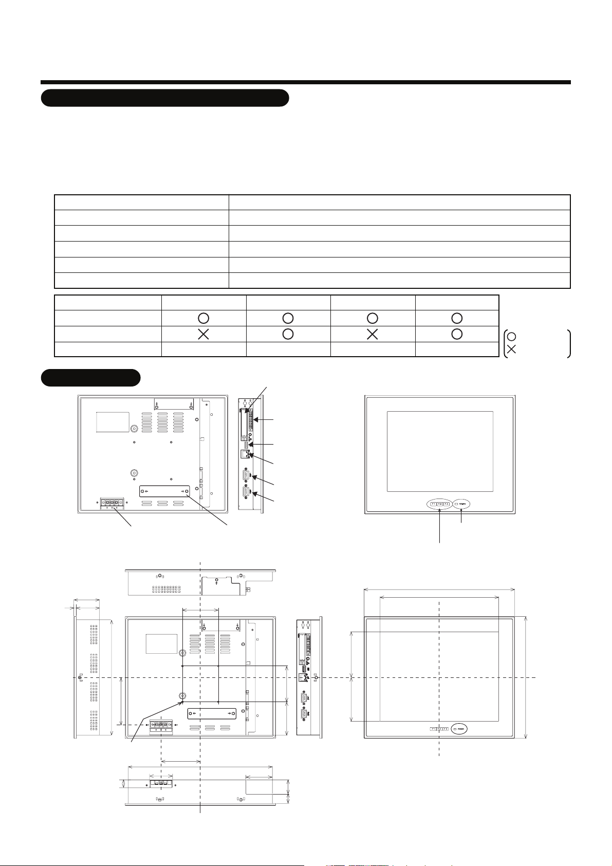
External View
54
549
242
Power input
terminal block
75
CF (Compact Flash)
card slot (CF card for
data files)
Input/Output port
USB
Ethernet
COM1(RS-232C)
COM2(RS-485)
PCI expansion unit
connector cover
POWER LED
Function switch (F1, F2, F3)
316
249
95.7591.75
256
99.3
M4 Tap (×4 pcs.)
(depth: 10 mm max.)
16
48
82.5
302
55.5
70 75
19 30
unit: mm
2
 Loading...