


6F8C1127
TOSHIBA Industrial Network Computer
(ULCS2)
Hardware Instruction Manual
February 2005
©TOSHIBA Corporation 2004 - 2005.
All Rights Reserved.


…………………………………………………………………………………………………
1. No part of this manual may be reproduced in any form without permission.
. The material in this manual may be revised without notice.
. Although it has taken all possible measures about the contents of this book,
please give notice, if there are contents which should be hard to understand,
and mistaken contents.
. Please understand that our company does not assume responsibility about the
influence of the result employed irrespective of the 3rd clause.
…………………………………………………………………………………………………
i

ii

g
r
r
Safety Precautions
This instruction manual and the labels affixed to the products or equipment give important
information for using products safety. It helps prevent damages to properties and hazard to
people who use them or work with them.
Make yourself familiar with the signal words and signs in the page, then read the safety
precautions that follow and always follow the instructions to avoid hazards.
■Explanation of signal words
Signal Words Meaning of Signal Words
WARNING
Indicates a potentially hazardous situation which could result in death o
serious injury, if you do not follow the instructions.
CAUTION
*1 :”Minor or moderate injury” means an injury and a burn with unnecessary hospitalization
and long-term going to hospital regularly for medical treatment.
*2 : “Property damage” means the expansion damage in connection with a house,
household effects, and livestock and a pet.
■Hazard alert shapes and symbols
Shapes & Symbols
Indicates a potentially hazardous situation which may result in minor o
moderate injury and/or property damage, if you do not follow the instructions.
Circle band with a diagonal slash means “Prohibition” or “You must not do.”
Prohibited action is shown in the circle or described near the circle.
Filled circle means “Mandatory Action” or “Do as indicated.”
Required action is shown in the circle or described near the circle.
Triangle means “Hazard Alerting” or “Be alert against hazard.”
The kind of hazard is shown in the trian
Meaning of Shapes and Symbols
le or described near the triangle.
iii

f
● Shut off a power supply immediately and pull
out a power supply plug from a wall socket,
when there is an unusual smell from
equipment or equipment overheated and
fumes.
• If it uses then, it will become the cause of a fire
and failure. Please request check to a service
station.
Pull out a power supply plug.
● Do not carry out repair of equipment,
reconstruction, and decomposition for the
customer itself.
• It may cause a fire, an electric shock, and a
burn of the equipment.
Decompose
About Equipment Itsel
WARNING
● Do not use equipment in a place which rain,
fog, etc. enter directly inside equipment.
• Rain and fog may adhere to equipment and it
may become the cause of a fire and an electric
shock.
Prohibition
● Shut off a power supply immediately and pull
out a power supply plug from a wall socket,
when you drop equipment or you give a shock
strong against equipment.
• If it uses then, it will become the cause of a fire
and emitting smoke. Please request check to a
service station.
Pull out a power supply plug.
iv

f
● Do not put equipment on unstable places,
such as a shaky stand top and a leaning place.
• Equipment drops on the floor or falls down and
causes your injury.
Prohibition
● Use a suitable power cord.
•
If the power cord which does not suit input
power supply conditions is used, it becomes
the cause of a fire and emitting smoke.
•
If it connects with the wall socket which does
not suit input power supply conditions, it
becomes the cause of a fire and emitting
smoke.
Mandatory Action
CONFIRM
About Equipment Itsel
WARNING
● Do not put metals such as a clip, and liquids
such as coffee, into the inside of equipment.
• It causes a fire and a smoke depended short.
• When they go into equipment, shut off a power
supply, pull out a power supply plug from a
wall socket, and request check from a service
station.
Prohibition
● Do not use the power cord or power supply
plug which is broken, damaged, and
processed.
• It becomes the cause of a fire, an electric
shock, and a burn.
• Exchange the damaged power cord for a new
one.
Prohibition
v

f
● Do not shut off a power supply or do not
perform attachment and detachment of
CompactFlash, and operation of the ejector,
during operation of a system.
• It causes that the data in processing is
destroyed or disappears.
●
•
Prohibition
Consult with your service station, when you
transfer equipment. Moreover, use the packing
box of exclusive use at the time of
transportation and conveyance of equipment.
You may be injured or equipment may break, if
you move the euipment by yourself.
Mandatory Action
SYSTEM
UNDER
OPERATI
CAUTION
About Equipment Itsel
● Do not use equipment in a dusty place.
• It will become the cause of the fire and the
smoke depended short circuitry, if the inside of
equipment is covered with dust.
Prohibition
● Do not use equipment in the place upon which
the open air containing corrosive gas or salt
trespasses directly.
• It becomes the cause of emitting smoke and
failure.
Prohibition
vi

f
● Set the equipment on an airy place.
• If the fresh air inlet of equipment is plugged up
or equipment is put on the place where it tends
to be filled with heat, the temperature inside
equipment will go up and it will become the
cause of a fire and failure.
Mandatory Action
● Do not put equipment on the place where the
temperature near the place and heating
instrument upon which direct rays shine etc. is
high.
• The temperature inside equipment goes up
and it becomes the cause of a fire.
Prohibition
CAUTION
About Equipment Itsel
● Do not use a cellular phone from the
equipment in a less than 3m place.
• It becomes the cause of the abnormalities of a
system, and data disappearance.
Prohibition
● Do not put on a place with much vibration.
• Equipment moves or falls and causes an
injury.
Prohibition
vii

f
● The lithium battery is used for this equipment.
• If you put a battery into fire, or handle it wrong,
the battery will heat and it will become the
cause of exploding and igniting.
• Dispose of a used battery according to the
regulation system which the area defines.
Mandatory Action
CAUTION
About Equipment Itsel
●
Install a circuit breaker etc. in the primary input
side of equipment.
●
By separating the power supply system of this
equipment with a circuit breaker, the other
apparatus can be prevented from the
malfunction of equipment.
Mandatory Action
viii

● Do not bend a power cord by force, do not pull,
do not twist, and do not put a heavy thing on a
code.
• It becomes the cause of the fire by short
circuitry and disconnection, and an electric
shock.
Prohibition
●
Be sure to extract with a power supply plug,
without pulling a power cord, when you pull out
a power supply plug from a wall socket.
●
If a power cord is pulled, a code will get
damaged and it will become the cause of a fire
and an electric shock.
Handling the Power Cord
CAUTION
● Please do not take out and insert a power
supply plug by the wet hand.
• It becomes the cause of an electric shock.
Prohibition
Mandatory Action
ix

A
CAUTION
Protection of programs or data
■ Make the backup of important contents periodically in consideration of destruction and
the loss of programs and data.
■ Make sure the following items during saving data.
• Do not turn off power while the system is working.
• Do not take out CompactFlash in power supply ON.
• The life of the CompactFlash is about 300,000 times of writing.
It is not possible to use the CompactFlash for the usage to save data periodically by
the application program (history and trend, etc.).
■ The files in CompactFlash may be broken when GIGABINE stops without passing a
normal shutdown sequence.
Moreover, the partition may be broken, and all files in the partition may become
inaccessible, too.
Consideration by the system of the installation of UPS etc. is recommended when
thought about a sudden power failure.
bout high availability of the system
The function to try reactivating in case of its breakdown attaches to this product, and it
reactivates automatically for temporary failure.
Build up the mechanism of the operation continuance by the alternative in the system to
which the interruption of the function is not permitted in consideration of the operation stop
of this product temporary a permanent breakdown in this product and the
above-mentioned.
It takes the start time that the start time of OS (about one minute) is necessary, and
depends on the application program in addition until this device starts. It returns to normal
operation after the above-mentioned time passes when downing by any chance and
reactivating.
Consider the backup device etc. for the system by which this interruption time becomes a
problem.
x

A
A
y
Although the safety measures to this equipment are fully performed, if equipment should
hang up, please turn off AC switch, or pull out AC power supply plug from a wall socket,
and turn off a power supply.
However, to the program in this case, or failure and loss of data, our company does not
take any responsibility.
The cautions display label is attached on the left side of equipment as shown in the
following figure, in order to prevent unprepared operation of ejector of the CompactFlash
under operation.
bout an emergenc
bout a cautions display label
xi

A
WARNING
bout a warning display label
The warning display label is attached on the appointed place of this equipment.
Inform a service station, when the label is lost, the sentence on the label is hard to see by
dirt.
xii

■Since this product was not developed and manufactured so that the equipment to affect
people's life etc. could be directly used for the system included (Note 1), do not use it for
those uses.
■Since special consideration (Note 3) is needed about employment, maintenance, and
management of a system when using it for the system (Note 2) containing the
equipment which is related to people’s safety, and does the serious influence for public
functional maintenance, consult with our or our company.
・ Note 1 The equipments to affect people's life etc. directly are as follows;
- Apparatus for medical treatments, such as a life support system and
apparatus for operating rooms
・ Note 2 The system containing the equipment which is related to the people’s safety
and does the serious influence for public functional maintenance means the
following.
- They are the operation control system of an important system, and a
system and a group transportation system, and an air-traffic control
system on the main opportunity control system of a nuclear power plant,
the safe protection system of a nuclear institution, and other safety.
Usagerestrictions
・ Note 3 The special deliberation means that you make the sufficient consideration
with the engineer of our company, and build a safe system (a foolproof
design, a fail-safe design, a redundant design being carried out).
・TOSHIBA does not take any responsibility about the damage produced by use under
conditions incongruent (a fire, an earthquake, the action by the third person, other
accidents, and misuse by customer, and an application program), in addition unusual.
・TOSHIBA does not take any responsibility about the subordinate damage (loss of
enterprise profits, enterprise discontinuation, change or disappearance of the contents
of memory, etc.) to be produced by using or being impossible to use this product.
・TOSHIBA does not take any responsibility about the damage produced without keeping
the contents indicated by the instruction manual.
・TOSHIBA does not take any responsibility about the damage produced from incorrect
operation by combination with the apparatus connected etc.
・Be sure to perform a scheduled inspection. TOSHIBA does not take any responsibility
about the damage produced by having neglected the scheduled inspection.
Qualification
xiii

xiv

INTRODUCTION
This manual aims at understanding the outline of equipment to people which have the TOSHIBA
Industrial Network Computer GIGABINE type II used, and letting you understand about the
various operation methods required for employment, and the correspondence at the time of obstacle
generating.
Please use correctly for often surely reading this manual, before use of this equipment.
This manual contains the following chapters.
Chapter 1: The Outline of GIGABINE
Chapter 2: The Composition of GIGABINE
Chapter 3: The Specification of GIGABINE
Chapter 4: Description of Operations
Chapter 5: Installation
Chapter 6: Preservation (Maintenance)
Please fully utilize this manual and profit by GIGABINE type II effectively.
Moreover, please also read collectively the description offered from a system integrator.
xv

……………………………………………………………………………………………………
Trademark
・GIGABINE is the registered trademark of TOSHIBA CORPORATION.
・CompactFlash and CF are the trademarks of SanDisk.
・Microsoft and Windows are the registered trademarks of U.S. Microsoft Corporation, in the
U.S. and other countries.
・UNIX is a registered trademark of Open Group, in the U.S. and other countries.
xvi
Each company may be using the name of goods as a trademark found in this book, respectively.
……………………………………………………………………………………………………

CONTENTS
Safety Precautions
Introduction
The Notation Method of This Manual
Explanation of a Term
The notice about embedded software
Chapter 1 The Outline of GIGABINE.......................................................1
1.1 The Purpose and the Use................................................................................................................................. 3
1.2 Feature ............................................................................................................................................................. 4
Chapter 2 The Composition of GIGABINE...........................................5
2.1 Appearance and Composition ......................................................................................................................... 6
2.2 Product Repertory ........................................................................................................................................... 7
Chapter 3 The Specification of GIGABINE...........................................9
3.1 Hardware Specification.................................................................................................................................10
3.2 Specification of Installation Environment..................................................................................................... 12
Chapter 4 Description of Operations....................................................13
4.1 Name and Function of Each Part................................................................................................................... 14
4.2 Operation (ON and OFF of Power Switch)................................................................................................... 22
Chapter 5 Installation ...........................................................................23
5.1 The Installation Direction and Its Method ................................................................................................... 24
5.2 Installation and Maintenance Space.............................................................................................................. 26
5.3 Cable Connection..........................................................................................................................................31
5.4 Power Supply Wiring....................................................................................................................................36
5.5 Grounding of System .................................................................................................................................... 37
Chapter 6 Preservation (Maintenance).................................................39
6.1 Inspection......................................................................................................................................................40
6.2 Failure Diagnosis .......................................................................................................................................... 41
6.3 Repair and Exchange..................................................................................................................................... 42
Appendix.................................................................................................43
Appendix1 Appearance and Size.....................................................................................................................44
Appendix 2 Screw Hole Pitch of the Bottom Side........................................................................................... 45
Appendix 3 Connector Pin Map......................................................................................................................... 46
xvii

The Notation Method of This Manual
This manual uses the following notation methods.
Marks
・ CAUTION : Be sure to read. If the mistaken handling or operation is carried out, a
phenomenon that people may get injured, or the material damage may be
generated is shown.
◆Requirement◆ : It is shown that you should protect in order not to cause disappearance of
data, failure of the equipment, and a performance fall, and that you should
know about specification or a function.
メモ
Memo
Example) : Concrete examples are shown.
※ : Another operation which can do the same thing is shown.
)
)
: Convenient knowledge and additional knowledge are shown.
『 』 : Other reference manuals are shown.
「 」 : The reference place in this manual is shown.
xviii

Explanation of a Term
The following terms may be used in this manual.
CompactFlash
The standard of the small memory card which U.S. SanDisk advocated and was developed
originally. A flash memory chip and a controller chip are mounted in the inside of a card, and it
can be recognized as a storage device of ATA conformity from PC etc. by processing with this
controller chip.
GIGABINE
Connection equipment between RS485 which is a control system network, and Ethernet which is
an information system network. Data exchange of both sides is performed by this equipment.
JHEXAS
Option software of GIGABINE. The software component group for building the supervisory
control system by Java.
Linux
OS compatible with UNIX developed for PC. Although only a kernel is meant in a narrow
definition, the package summarized including peripheral software is meant in many cases. It is
distributed according to GPL (Ge neral Public License).
xix

The Notice about Embedded Software
The software shown below is included in the TOSHIBA Industrial Network Computer GIGABINE.
The notice based on the contract of IBM Corporation
CONTAINS
IBM Developer Kit for Linux
Runtime Modules
(c) Copyright IBM Corporation 1997-2000
All Rights Reserved
(TM)
The notice based on the contract of Apache Software Foundation
This product includes software developed by the Apache Software Foundation (http://www.apache.org/).
, Java
(TM)
2 Technology Edition, Version 1.3.0
xx

Chapter 1 The Outline of GIGABINE
Chapter
1
The Outline of
GIGABINE
1

Chapter 1 The Outline of GIGABINE
The TOSHIBA Industrial Network Computer GIGABINE type II is the equipment which equips the
interface of the control system network which performs RS485 communication, and the information
system network which performs Ethernet communication, and performs the routing function between the
both.
With the various flexible functions of HEXABINE built in, the performance was raised by leaps and
bounds and the scope of this equipment was expanded widely.
2

1.1 The Purpose and the Use
As shown in a figure, GIGABINE type II is located between an information system Network layer and
a control system Network layer, and performs the protocol conversion between an information system
network and a control system network.
Seamless access between the information system network which based Ethernet, and the control system
network which performs RS485 communication is realized.
Information
Network
Ethernet
Chapter 1 The Outline of GIGABINE
GIGABINE
Control Network RS485
Control Node
・・・・
… …
↑Sensor / Actuator ↑Sensor / Actuator
Control Node
Example of the System Configuration
Control Node
… …
GIGABINE
Control Network RS485
Control Node
・・・・
3

Chapter 1 The Outline of GIGABINE
1.2 Feature
GIGABINE type II is the equipment with the feature shown below.
・It is the higher rank model which raised the performance of HEXABINE by leaps and bounds.
・The whole equipment is manufactured compact in order to make an installation space small.
・It has the environment-proof nature suitable for factory automation use, and the continuation
operation for 24 hours is possible.
・The design without the life parts, such as a cooling fan brought us “maintenance-free.”
4

Chapter 2 The Composition of GIGABINE
Chapter
2
The Composition of
GIGABINE
5

Chapter 2 The Composition of GIGABINE
2.1 Appearance and Composition
The appearance of GIGABINE type II and a composition article (accessories) list are shown below.
Composition article (accessories) list
Instruction manual (this manual) : 1
Rack-mount kit (option) : 1
6

2.2 Product Repertory
The product repertory of GIGABINE type II has case specification, memory capacity, and the kind
following by the difference in an interface.
In case you place an order, please specify in product code shown below.
Product Repertory
Product code of GIGABINE
1 2 3 4 5 6 7 8 9 10 11 12 13 14
U L C S 2 * * * * *****
Chapter 2 The Composition of GIGABINE
Details「3.1 Hardware specification」
)
An underline spec. means a standard type and a
hatched item means a user selectable.
Cabinet Specification
B: Metal case
Capacity of CompactFlash
0: None
Capacity of the Main Memory (SDRAM)
1: 128MB
L
ONWORKS
0: None
Number of Ethernet Channels
1: 1ch, 2: 2ch
Rack-mount Kit
0: None
Power Cord Cramp
0: None
Serial Port 1 Specification
2: RS-232C, 4: RS-485
, 1: 128MB, 2: 256MB, 5: 512MB
, 2: 256MB
Specification
, F: TP/FT-10(FTT-10A), 1: TP/XF-1250
, 1: With Kit
,1: With Cord Cramp
7

Chapter 2 The Composition of GIGABINE
8

Chapter 3 The Specification of GIGABINE
Chapter
3
The Specification of
GIGABINE
9

Chapter 3 The Specification of GIGABINE
3.1 Hardware Specification
The hardware specification of GIGABINE type II is shown below.
■Hardware Specification
Item Specification
CPU 32-bit CPU + Neuron Chip
Main Memory 128MB/256MB/512MB Memory
Capacity
Interface
Power Supply
Environmental
Conditions
Outside Size
Compact Flash 128MB/256MB
10BASE-T/100BASE-Tx
Ethernet
Serial Interface
RS-485, RS-232C
Digital
Input/Output
Rated Voltage 100/240Vac
Tolerance Range 85~132Vac/180~264Vac
Rated Frequency 50/60Hz
Power Consumption
Temperature
Humidity
Weight 2.5kg
Two port are provided for the standard type
Maximum cable length: 100m
Maximum transmission rate: 115,200bps, respectively.
Serial Port-1: For general-purpose communication, RS-485 and
RS-232C selection
Serial Port-2: For maintenance console, RS-232C
Insulation: Serial Port-1: insulated against the internal circuit
Serial Port-2: un-insulated against the internal circuit
Maximum cable length: RS-232C 15m,RS-485 500m
Digital Input: 4-point
Digital Output: 4-point
30VA
Operation: 0~50℃
Storage: -20~60℃
Operation: 10~90%RH (Without C on de nsat i o n)
Storage: 10~90%RH (Without Conde nsati o n)
370(W)×39(H)×198(D)
Unit in mm (A projection thing is not included.)
10

Chapter 3 The Specification of GIGABINE
■Digital Input/Output Specification
Item Specification
Power Supply Voltage 24V~5V±5%
Insulating Block
Connector of GIGAGBINE Side FUJITSU: FCN-365P024-AU
Recommended Cable OMRON: XW2Z-□□□A
Recommended Terminal Block OMRON: XW2D-20G6
Number of Input Points 4-point
Input Signal Dry contact point
Input
Output
Input Filter Approx. 5ms
Input Current MAX approx. 10mA/point
Over-Current Protection Constant current diode mounted for each point
Number of Output Points 4-point
Output Signal Dry contact point
Output Current MAX approx. 50mA/point
Digital Input/Output
Eight-point packed insulation with signal common
11

Chapter 3 The Specification of GIGABINE
3.2 Specification of Installation Environment
(1) Ambient Conditions
The specification of ambient conditions is shown below.
■Ambient Specification
Item Operation Storage
Temperature 0~50℃ -20~60℃
Temperature
Change
Humidity
(without condensation)
Vibration 2.45m/s2 or the less 4.91m/s2 or the less
Shock 24.5m/s2 or the less 49.0m/s2 or the less
(2) Power Supply Conditions
The specification of power supply conditions is shown below.
15℃/H 15℃/H
10~90%RH
10~90%RH
(without condensation)
■Power Supply Specification
Item Specification
Rated Voltage
Power Supply
Grounding
Tolerable Range 85~132Vac/180~264Vac
Frequency 50/60Hz±3Hz, or the less
Tolerable Power
Interruption
100/240Vac
Single phase with grounding
20ms, or the less
Exclusive grounding
(Grounding resistance: 100ohms, or the less)
12

4
Chapter 4 Description of Operations
Chapter
Description of
Operations
13
Chapter 4: Description of Operations
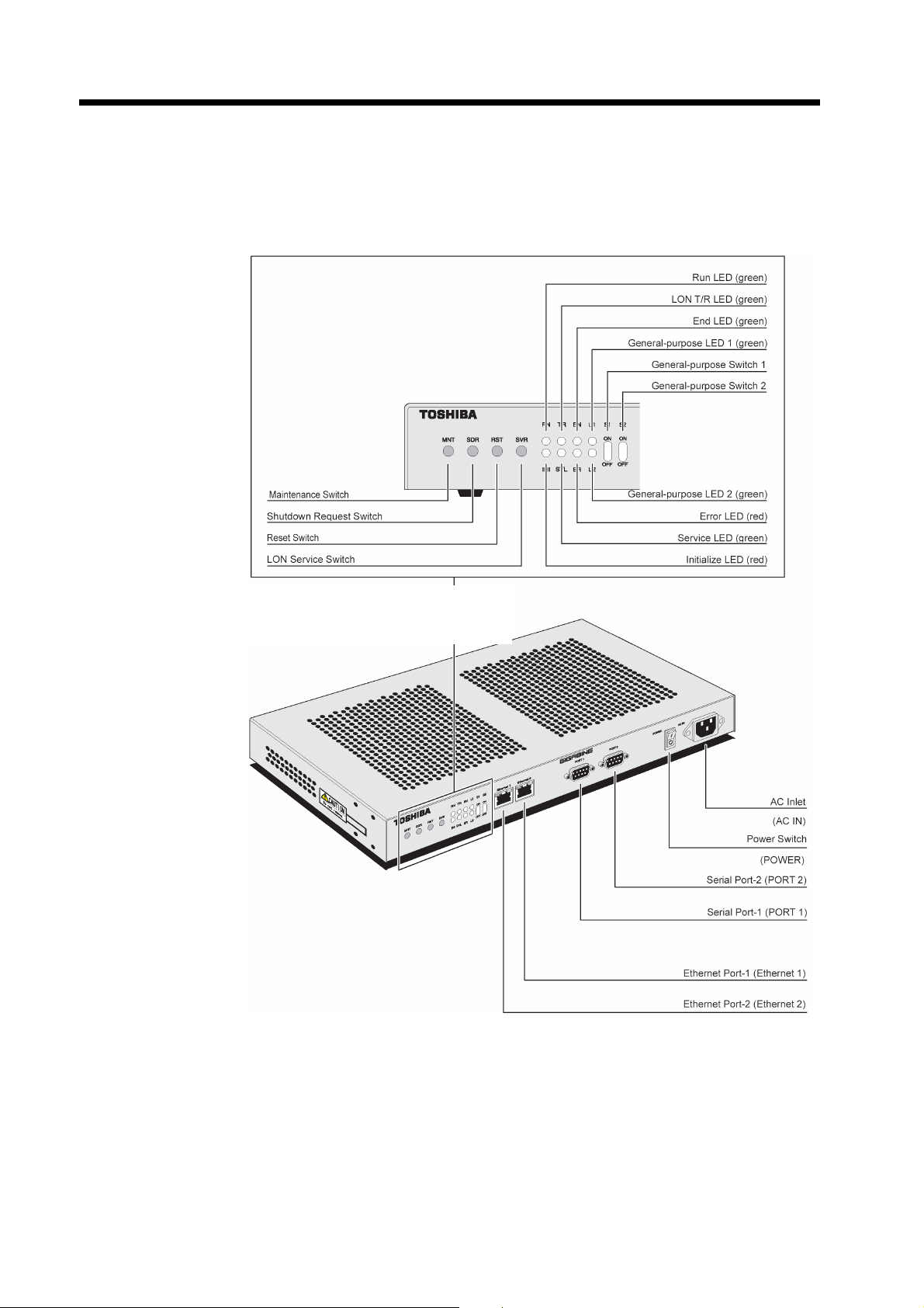
4.1 Name and Function of Each Part
The name and function of each part are shown below.
Metal Case Type:
■GIGABINE type II seen from the front
■GIGABINE type II seen from the forward left side
14

Chapter 4: Description of Operations
(1) LED Display
There are eight kinds of the following LED in the front panel of GIGABINE type II.
・ Run LED(green/RN)
・ Initialize LED(red/INI)
・ LON T/R LED(green/TR)
・ Service LED(green/SVL)
・ End LED(green/EN)
・ Error LED(red/ER)
・ General-purpose LED(green/L1, L2)
■Run/Initialize/End/Error LED (RN/INI/EN/ER)
These LEDs are turned on according to the internal state of GIGABINE type II.
LED Status
RN It illuminates green when the equipment is under operation.
INI
EN It illuminates green when the shutdown of the equipment is completed.
ER
It illuminates red when the equipment is under initialization, writing to
CompactFlash, and maintenance mode.
It illuminates red when the user program under initialization, and at the time of
stop.
It blinks by user program setting.
■General-purpose LED(L1/L2)
These LEDs can be set up a display state by the user program.
LED Status
It illuminates green the main unit is under normal operation.
L1
L2
When its operation is set by the user program, it follows the setting of the user
program.
It illuminates green when the CompactFlash starts, and it blinks when the
equipment is under normal operation.
When its operation is set by the user program, it follows the setting of the user
program.
15

Chapter 4: Description of Operations
By investigating the length of the blink interval of ER LED, the cause of unusual operation of
equipment is analyzable.
Red-Short→ Green-Long→Red-Short
①
→Green-Long→……
Red-Short→Green-Short→ Red-Short
②
→Green-Short→……
Red-Long→Red-Short→Green-Short
③
→……
The combination pattern of the state of ① to ③ is shown in the following table. The following blink
is repeated, in the cycles of about 5 seconds.
① ●○○○●○○○ Illu minates red twice in one cycle.
② ○●○●○●○● Green illuminates up at equal intervals with red.
③ ●●●○○○●○ Lon g interval blink, short interval blink
①+② ●●○●●●○● Illuminates green twice in one cycle.
①+③ ●●●○●○●○ Illuminates green three times in one cycle.
②+③ ●●●●○●●● Illuminates green once in one cycle.
①+②+③ ●●●●●●●● Illuminates red
Status LED Display Cause of Error
Java VM stops, STAT_ERR1 is set by the program.
STAT_ERR2 is set by the program.
STAT_ERR3 is set by the program.
●: illuminates red ○: illuminates green
■LON T/R LED(green/TR)
This LED illuminates green while the LON interface of GIGABINE type II performs data transmission.
(It is not used with this product)
■End LED(green/EN)
This LED illuminates green when GIGABINE type II completes shutdown operation.
■Service LED(green/SVL)
This LED expresses the service state of a neuron chip. (It is not used with this product)
Moreover, yellow and green LED are embedded at each modular connector of the Ethernet port, and
each LED expresses the following states, respectively.
■TRX LED(yellow)
While equipment is performing transmission operation via the corresponding Ethernet port, this LED
illuminates or blinks.
16

Chapter 4: Description of Operations
■LINK LED(green)
When the corresponding Ethernet port is connected normally, this LED illuminates or blinks.
TRX LED
LINK LED
(2) Push Button Switch
There are four kinds of following switches on the front panel of GIGABINE type II.
■Reset Switch (RST): for maintenance
A push on a reset switch reboots the equipment.
Carry out reset operation, after shutdown of the equipment.
■Maintenance Switch (MNT): for maintenance
Do not usually touch this switch, since it is prepared for maintenance.
■LON Service Switch (SVR)
It is not used with this product.
■Shutdown Request Switch (SDR) : for maintenance
It is the switch which makes GIGABINE type II shutdown. If this switch is pushed, GIGABINE type II
will go into shutdown operation.
Completion of shutdown operation of GIGABINE type II illuminates EN LED.
◆
Requirement
Turn off the power supply switch or press the reset switch after the shutdown completion.
If the power switch of the equipment is turned off or the equipment is reset before the completion of a
shutdown, the write-in data to CompactFlash may be lost.
◆
(3) Snap Switch
■Snap Switch (S1, S2): for general purpose
The ON/OFF state of these switches can be read by the user program.
Be sure the following items.
・ Do not touch on the switch for maintenance (Reset Switch, Maintenance Switch,
and Shutdown Request Switch).
the possibility of the data disappearance by data destruction of a memory.
・ Do not operate a switch by the wet hand.
CAUTION
If it touches during equipment operation, there is
17

Chapter 4: Description of Operations
r
(4) Communication Port
・Ethernet Port-1
This port is used as 10BASE-T/100BASE-Tx interface. The eight pin modular plug of the
twisted-pair cable is connected.
・Ethernet Port-2
This port is used as 10BASE-T/100BASE-Tx interface. The eight pin modular plug of the
twisted-pair cable is connected.
This port does not exist in an one Ethernet channel model.
・Serial Port-1
It is a serial port for high-speed communication. It has the control signal required in order to support
modem connection. It can be selected from RS-485 or RS-232C according to a use. D-Sub9 pin male
connector is mounted for this port.
・Serial Port-2: for maintenance
It is the serial port of the RS-232C interface for maintenance consoles. D-Sub9 pin male connector is
mounted for this port.
Serial Port-2 cannot be used for data communications, since it is mounted fo
maintenance consoles.
CAUTION
18

Chapter 4: Description of Operations
r
r
(5) Power Switch
It is the switch which performs ON/OFF of AC power supply of equipment.
(6) AC Inlet
AC power cord is connected to this inlet. The power supply of equipment can be used for both a
100Vac system and a 200Vac system. Moreover, there is no adjustment of the voltage change to
operating voltage.
Dtails「3.1 Hardware Specification」
ince the AC power cord is not attached to GIGABINE type II, prepare the AC powe
ord according to the safety requirements of each country.
o not use any AC power cord other than the AC power cord with 3-pin plug
dapted to the input voltage.
o not use it with the grounding pin disconnected.
CAUTION
)
(7) CompactFlash Slot
The slot of a CompactFlash card is prepared in the left side of GIGABINE type II.
A CompactFlash card is mounted here. The software update in the field by exchanging CompactFlash
became easy. The eject button attached to the slot side is pushed, and CompactFlash is taken out from
the equipment.
Do not perform attachment and detachment of CompactFlash, and operate the
ejector during system operation.
・It becomes the cause which data in processing is destroyed or disappears.
CAUTION
CompactFlash Slot
Ejecto
19

Chapter 4: Description of Operations
r
(8) Function Switch
The function switch is prepared for the bottom of GIGABINE type II.
The setup at the time of factory shipments of a function switch is as follows.
1 2 3 4 5 6 7 8
ON OFF OFF OFF OFF OFF OFF OFF
■The Bottom View of GIGAIBNE type II
Function Switch
Four screw holes for surface-of-a-wall attachment
AC Inlet Side
RS-485 Mode Setting Switch
Do not operate this switch. This function switch at the bottom is a switch only fo
servicemen.
LED Display Side
CAUTION
4-M4 screw holes
20

Chapter 4: Description of Operations
(9) Port 1 RS-485 Operation Mode Setting Switch
■The Bottom View of GIGAIBNE type II
Four screw holes for surface-of-a-wall attachment
AC Inlet Side
Internal Block Diagram
RTS
TXD
LED Display Side
RS-485 Mode Setting Switch
1 ON Termination resistor exists between TX(+)~TX(-)
OFF Termination resistor does not exist between TX(+)~TX(-)
2 ON Termination resistor exists between RX(+)~RX(-)
OFF Termination resistor does not exist between RX(+)~RX(-)
3 ON Half duplex operation (note 1)
OFF Full duplex operation (note 2)
4 Not in use
(Note 1) The transmitting data of a self-station is not received by itself
during data transmission.
(Note 2) The transmitting data of a self-station is also received by itself
during data transmission.
1
TX(+)
TX(-)
100Ω
2>
1>
4-M4 screw holes
RXD
2
100Ω
3
10kΩ
RX(+)
RX(-)
3>
4>
21
Chapter 4: Description of Operations
4.2 Operation (ON and OFF of Power Switch)
The operation method of power supply ON/OFF of the equipment is shown below.
(1) ON Operation of Power Switch
The power supply switch at the front of equipment is turned ON. (It pushes down from the "O" side to
the "|" side)
(2) OFF Operation of Power Switch
The power supply switch at the front of equipment is turned OFF. (It pushes down from the "|" side to
the "O" side)
Do not operate the equipment by the wet hand.
WARNING
22

5
Chapter 5 Installation
Chapter
Installation
23

Chapter 5: Installation
d
5.1 The Installation Direction and Its Method
The installation direction of the equipment and its method have four kinds of the rack-mounted
installation, plane installation, and surface-of-a-wall installation shown below.
In rack-mounted installation, it is attached in a 19 inch rack by using the rack-mount kit. In case of
plane installation, please install downward by making the bottom of this equipment the uneven level
place which is not. In surface-of-a-wall installation, the bottom of this equipment is opposed to the
uneven surface of a wall which is not, and it is installed. The screw hole for fixing this equipment is
prepared for the bottom (four places).
In addition, this equipment cannot be installed by any methods other than the following four kinds.
Screw hole pitch「Appendix 2 Screw Ho le Pitch of the Bottom Side」
)
(1) Rack-mounted Installation
・Support parts are required for the back and
bottom side of this equipment.
Insulate a rack and an attache
rack-mount kit with a plastic
screw, a miler sheet, etc.
(3) Surface-of-a-wall Installation-A
・The installation method to the surface of a wall
which turned the front up
(2) Plane Installation
・The standard installation method
(4) Surface-of-a-wall Installation-B
・The installation method to the surface of a wall
which turned the left side up
24

Chapter 5: Installation
r
r
・ Select from four kinds of the above figure, when the equipment is installed.
When installing by the other method, unusual operation and failure may be
brought to the equipment.
・ Be sure to fix in surface-of-a-wall installation using the screw hole at this bottom
of equipment (four places).
When equipment is fixed by methods other than specification, the equipment
may fall and the failure of the equipment may be brought.
・ It is recommended to fix in a screw hole (four places) at the bottom fo
prevention of equipment fall also in plane installation.
・ Insulate a rack and an attached rack-mount kit with a plastic screw, a mile
sheet, etc.
CAUTION
In addition, please use a plastic screw for fixation.
25

Chapter 5: Installation
5.2 Installation and Maintenance Space
When installing equipment, each space of an "installation space" and a "maintenance space" is required.
The direction of an installation space and a maintenance space changes with each installation methods.
Installation space:
It is the space which is needed at least in order to use or employ this equipment.
Maintenance space:
It is the space which is needed in case a maintenance person performs check and maintenance for this
equipment.
(1) Installation Space
The space more than the following size is required for an installation space to each field of this
equipment. Moreover, install the equipment in the place which can perform not sealing but moderate
air circulation.
26

Item
Installation
Space
Chapter 5: Installation
Unit in mm
Directi
on
Top 50 100
Bottom 50 0 0 0
Front 100 100 100 100
Rear 100
Right
Left
*1): ”Surface-of-a-wall contiguity is possible” means that the field can be close to the surface of a
Rack-mounted
Installation
Surface-of-a-wall
contiguity is possible
Surface-of-a-wall
contiguity is possible
wall, and it can be installed. It is not surely the meaning that it must be close to the surface of
a wall, and must be installed.
*1)
*1)
Plane Installation
Surface-of-a-wall
contiguity is possible
100 100 100
100 100 100
*1)
Surface-of-a-wall
Installation-A
Surface-of-a-wall
contiguity is possible
100
Surface-of-a-wall
contiguity is possible
*1)
contiguity is possible
Installation-B
Surface-of-a-wall
*1)
Surface-of-a-wall
*1)
27

Chapter 5: Installation
■Dust Conditions
GIGABINE type II should be used in the environment with a dirt concentration 0.3mg/m3, or the less.
Dirt concentration is about 0.07 mg/m
in the place of smoking permission.
GIGABINE type II should be installed in the environment whose dirt concentration 0.3 mg/m
less.
■Corrosive Gas
GIGABINE type II should be installed in the environment where the sum total of the evaluating point
of each corrosive gas factor becomes 25 or less points, with reference to the following table.
Classification
Environmental Factor
Annual Average
Temperature (℃)
Annual Average
Humidity (%)
Gas(ppm)
Corruption Degree
(Equivalent Salinity)
(mg/cm2)
The Sum Total of the Evaluating Point=A+B+C1+C2+C3+C4+C5+D
A
B
SO2 C1
NO2 C2
H2S C3
CL2 C4
NH3 C5
D
3
in the clean office of prohibition of smoking, about 0.2 mg/m3
3
, or the
1 2 3 4
Measu
red
Value
Evalua
tion
Value
Measu
red
Value
Evalua
tion
Value
Measu
red
Value
Evalua
tion
Value
Measu
red
Value
Evalu
ation
Value
≦ 20 1 ≦ 25 2 ≦ 30 4 >30 8
≦ 50 1 ≦ 60 8 ≦ 75 16 >75 24
≦.04 1 ≦.08 3 ≦ .2 6 ≦5 9
≦.02 1 ≦.05 3 ≦ .1 6 ≦5 9
≦.003 1 ≦.01 8 ≦ .1 14 ≦10 20
≦.002 1 ≦.01 10 ≦ .1 20 ≦1 30
≦.1 1 ≦ 1 2 ≦ 10 4 ≦100 8
≦.03 1 ≦.06 8 ≦.12 16 >.12 24
28

Chapter 5: Installation
t
t
t
(Calculation Example)
Environmental Conditions Evaluating Point
Annual Average Temperature : 23℃ A=2 point
Annual Average Humidity : 55% B=8 point
SO2 : 0.03ppm C1=1 point
NO2 : 0.04ppm C2=3 point
H2S : 0.002ppm C3=1 point
CL2 : 0.001ppm C4=1 point
NH3 : 0.05ppm C5=1 point
Corruption Degree : 0.5ppm D=8 point
The Sum Total of the Evaluating Point: 2+8+1+3+1+1+1+8=25 poin t
Perform the following items.
・Install the equipment in the place appropriate for the specified installation space
conditions.
・Install the equipment in the place appropriate for the specified environmental
conditions.
Be careful of the following items.
・Do not install the equipment in a place which the open air containing corrosive gas
or salt enters directly.
・Do not install the equipment in the high temperature places where direct sunligh
hits, near the heating instrument, etc.
・Install the equipment in the place with moderate air circulation instead of airtigh
space.
・Do not push the ejector of the CompactFlash of the left side of the equipmen
during installation.
WARNING
CAUTION
29

Chapter 5: Installation
(2) Maintenance Space
A maintenance space is required, in case installation or maintenance is performed. A plane view shows
a maintenance space below.
*1) : The range in which a maintenance person works is shown. In case equipment is fixed, it is
Back Side
Front Side
GIGABINE type II
1,000
*1)
1,000
*1)
Unit in mm
: Maintenance Space
: Installation Space
Plane View
necessary to prepare the space to which the equipment front (cable connection side) is turned
to the front, and a maintenance person works.
30

5.3 Cable Connection
t
k
In case of the connection of AC power cord and a signal cable, connect the cables in the following
procedure.
(1) Connection of AC Power Cord
・Confirm that the power switch of GIGABINE type II is OFF.
・The code clamp of AC inlet is raised upwards, and AC power cord is inserted in AC inlet.
・A clamp is pushed down to the front and AC power cord is fixed.
・AC power cord is inserted in a power supply wall socket.
Perform the following items.
・Check whether power supply conditions conform to specification given in this boo
before inserting a power supply plug.
・Do not use the power cord or power supply plug which is broken, damaged, and
processed.
・Do not take out and insert a power cord by the wet hand.
Perform the following thing about a power cord and a power supply plug.
・ Have the portion of a plug by hand and extract it, when you pull out a power cord
from a power supply wall socket.
・ Perform extraction and insertion of a power supply plug after checking that a
power supply switch is "OFF."
・ Do not bend a power cord by force, do not pull, do not twist, and do not put a
heavy thing on a cord. Moreover, the ground of a power supply wall socke
should check surely connecting.
・ Since the AC power cord is not attached to GIGABINE type II, prepare the AC
power cord according to the safety requirements of each country.
・ Do not use any AC power cord other than the AC power cord with 3-pin plug
adapted to the input voltage.
・ Do not use it with the grounding pin disconnected.
Chapter 5: Installation
WARNING
CAUTION
31

Chapter 5: Installation
(2) Connection of Ethernet Cable
・The modular plug of the twisted-pair cable for Ethernet signals is inserted in the modular jack of
"Ethernet port-1 / 2" of a front panel.
Push in until it sounds "click", in the case of modular plug insertion. Even if the power supply of
equipment is switched on, extraction and insertion of a cable is possible.
CAUTION
Perform the following items in case of connection of the Ethernet signal cable.
・ A twisted-pair cable should be used the cable suitable for specification.
・ Use a cable with shield covering, in order to meet CE Marking regulations.
・ Have the portion of a plug by hand and extract it, when you pull out a cable from
a modular jack.
・ Do not bend a power cord by force, do not pull, do not twist, and do not put a
heavy thing on a cable.
・ Do not take out and insert a cable by the wet hand.
・ Make the right connection according to directions.
(3) Connection of Serial Port-1/2
・Confirm that the power switch of GIGABINE type II is OFF.
・The connector of a signal cable is inserted in the connector of "PORT 1 or 2" of the equipment front
panel.
・The connector is fixed to "PORT 1 or 2" on the front panel of the equipment with the fixed screw (two
right and left) of connector.
Fix a connector firmly with the screw of two right and left.
Turn off the power supply of this equipment, when you take out and insert a cable.
32

Chapter 5: Installation
Perform the following items in case of connection of the serial signal cable.
・ A serial cable should be used the cable suitable for specification.
・ Use a cable with shield covering, in order to meet CE Marking regulations.
・ Check the pin number of a connector on "Appendix 3 Connector Pin Map", when
you manufacture a cable.
・ Pin arrangement of Serial Port -1 changes with specifications.
・ Do not take out and insert a cable, when the power supply of this equipment is
switched on.
・ Have the portion of a plug by hand and extract it, when you pull out a cable from
the connector of the equipment.
・ Do not bend a power cord by force, do not pull, do not twist, and do not put a
heavy thing on a cable.
・ Do not take out and insert a cable by the wet hand.
・ Make the right connection according to directions.
CAUTION
33
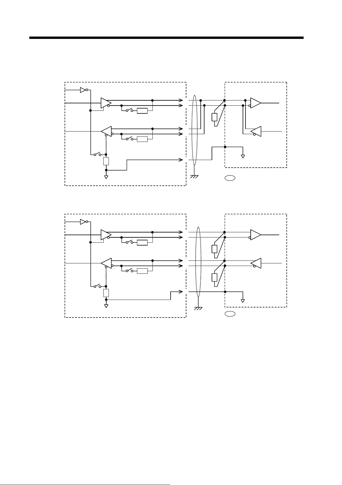
Chapter 5: Installation
●RS-485 The example of 2 line system cable connection
RTS
TXD
1
OFF
GIGABINE
TX(+)
TX(-)
2>
1>
I/F of Opposite Device
TRX(+)
TRX(-)
RXD
RXD
RX(+)
RX(-)
2
ON
3
OFF
3>
4>
5>
ULCS2
LG
FG
●RS-485 The example of 4 line system cable connection
RTS
TXD
RXD
1
ON
2
ON
3
OFF
GIGABINE
TX(+)
TX(-)
RX(+)
RX(-)
2>
1>
3>
4>
5>
TXD
LG
: Shield
I/F of Opposite Device
TRX(+)
TRX(-)
RXD
TXD
34
LG
LG
FG
: Shield

Chapter 5: Installation
r
g
(4) Connection of the Cable for the Connector Terminal Block Conversion Unit
・The connector of the equipment back panel is fixed with the fixed screw (two right and left) of
connector.
Fix the screws firmly by two right and left.
Turn off the power supply of this equipment in case of extraction and insertion of a cable.
Perform the following items in case of connection of the cable for the connecto
terminal block conversion unit.
・A cable should be used the cable suitable for specification.
・Have the portion of a plug by hand and extract it, when you pull out a cable from
the connector of the equipment.
・Do not bend a power cord by force, do not pull, do not twist, and do not put a heavy
thing on a cable.
・Do not take out and insert a cable by the wet hand.
・Make the ri
ht connection according to directions.
CAUTION
35

Chapter 5: Installation
5.4 Power Supply Wiring
In accordance with the power supply specification of GIGABINE type II, a circuit breaker is installed
in the primary side of a power supply wall socket.
Grounding of GIGABINE type II is connected to an exclusive grounding line (100ohms or the less of
grounding resistance).
Perform the following items.
・ Please connect with the power supply wall socket which suited the specified
power supply conditions.
・ Be sure to install a circuit breaker in the primary side of a power supply wall
socket.
Grounding is considered as exclusive grounding for GIGABINEs 100ohms or the
less. Be sure the following items.
・Do not share a common grounding of the apparatus with a possibility of generating
electric load change or the big electric noise, such as an air-conditioner, a
refrigerator, a motor, a vending machine, and a welding machine.
WARNING
CAUTION
36

5.5 Grounding of System
The example of the system incorporating GIGABINE type II is shown in the following figures.
GIGABINE type II is grounded for the grounding terminal of exclusive use (100ohms or the less of
grounding resistance), and dissociates and grounds with the electric apparatus which may generate big
load change and the electric noise.
Moreover, to a cabinet, as shown in the following figure, GIGABINE type II is floated from a cabinet,
and it is mounted and separated with grounding for cabinets.
Chapter 5: Installation
Insulation Processing
Insulation Processing
Cabinet
Insulation Sheet
Inside Panel
Grounding is connected to the grounding line (100ohms or the less of grounding resistance) of
exclusive use.
37

Chapter 5: Installation
38

6
Chapter 6 Preservation (Maintenance)
Chapter
Preservation
(Maintenance)
39

Chapter 6: Preservation (Maintenance)
quip
6.1 Inspection
The durable life of this equipment is ten years.
However, this equipment has life parts shown in the following table. When this equipment is installed
in the temperature range which satisfies the conditions shown in the following table, it can be used as
maintenance-free for ten years.
■Life Parts List
Life Parts Durable Life Ambient Temperature of Equipment
Aluminum Electrolytic Capacitor
(Power Supply Module)
Lithium Battery 10 years 30℃
CompactFlash
*: When CompactFlash is procured by the customer, the writing time might be different.
Moreover, please carry out the following thing periodically as preventive maintenance. In addition,
please contact your service station about a request of scheduled inspection service.
)
10 years 35℃
300,000 times of
writing *
Environmental Conditions「3.2 Specification of Installation Environment」
-
(1) Dirt of Equipment
The dirt of equipment is wiped out with the cloth which attached thin neutral detergent is extracted
firmly. Furthermore, it is wiped out with dry cloth once more.
If a detergent spray is covered over equipment or it is wiped out with medicine, such
as alcohol, benzine, and thinner, the failure of the equipment may occur and the
communication data etc. may disappear.
CAUTION
(2) Inspection of the Ambient Conditions
Clean and check the surroundings of the equipment periodically.
If it continues using equipment while the fresh air inlet of equipment had been
closed, an internal temperature rises, a fire may break out, or the failure of the
equipment may occur and communication data may disappear.
Clean and check periodically the circumference of the fresh air inlet of the
e
ment.
CAUTION
40

6.2 Failure Diagnosis
Please read this chapter before judging that it is failure, if the following phenomenon occurs in the
handling of this equipment.
The contents of a check and a solution are shown below.
(1) Power Supply Is Not Turned On.
Phenomenon Check Point Solution
Is AC power cord inserted in the
A power supply is not
turned on.
RN LED (green) does
not light up.
(2) The Display of LED
Phenomenon Check Point Solution
TRX LED(green) and
LINK LED(yellow) do
not light up.
INI LED(red) and ER
LED(red) light up. ER
LED(red) repeats blink.
power supply wall socket?
Is the power supply switch turned
on?
Does the power come to the
power supply wall socket?
Is the modular jack connected to
the Ethernet port?
Is the apparatus of the opposite
side connected?
Since it is failure, please contact your service station.
Chapter 6: Preservation (Maintenance)
Once turn off the power supply switch
in this front of equipment, and insert in
a wall socket.
Turn ON a power supply switch.
Check that the circuit breaker by the
side of power supply primary turns on.
Insert a modular jack.
Connect the apparatus of the opposite
side.
(3) In Case of Abnormalities or Failure
Phenomenon Solution
An unusual smell and
unusual overheating
have been noticed.
Turn off a power supply switch and pull out AC power cord.
Since it is failure, please contact your service station.
41

Chapter 6: Preservation (Maintenance)
6.3 Repair and Exchange
When the failure occurs in this equipment, TOSHIBA will exchange the whole equipment.
Please contact your service station.
42

Appendix
Appendix
43

Appendix
Appendix 1 Appearance and Size
44

Appendix 2 Screw Hole Pitch of the Bottom Side
A total of four screw holes for this equipment fixation for surface-of-a-wall attachment (M4 size) is in
the equipment bottom.
Please attach screw hole size and the depth within 6-8mm in M4 size.
Please refer to the bottom side layout shown below and a screw hole sectional view about a detailed
size.
Metal case type:
Screw Hole × 4
Appendix
AC inlet side
Bottom Side View
LED display side
Unit in mm
45
Appendix
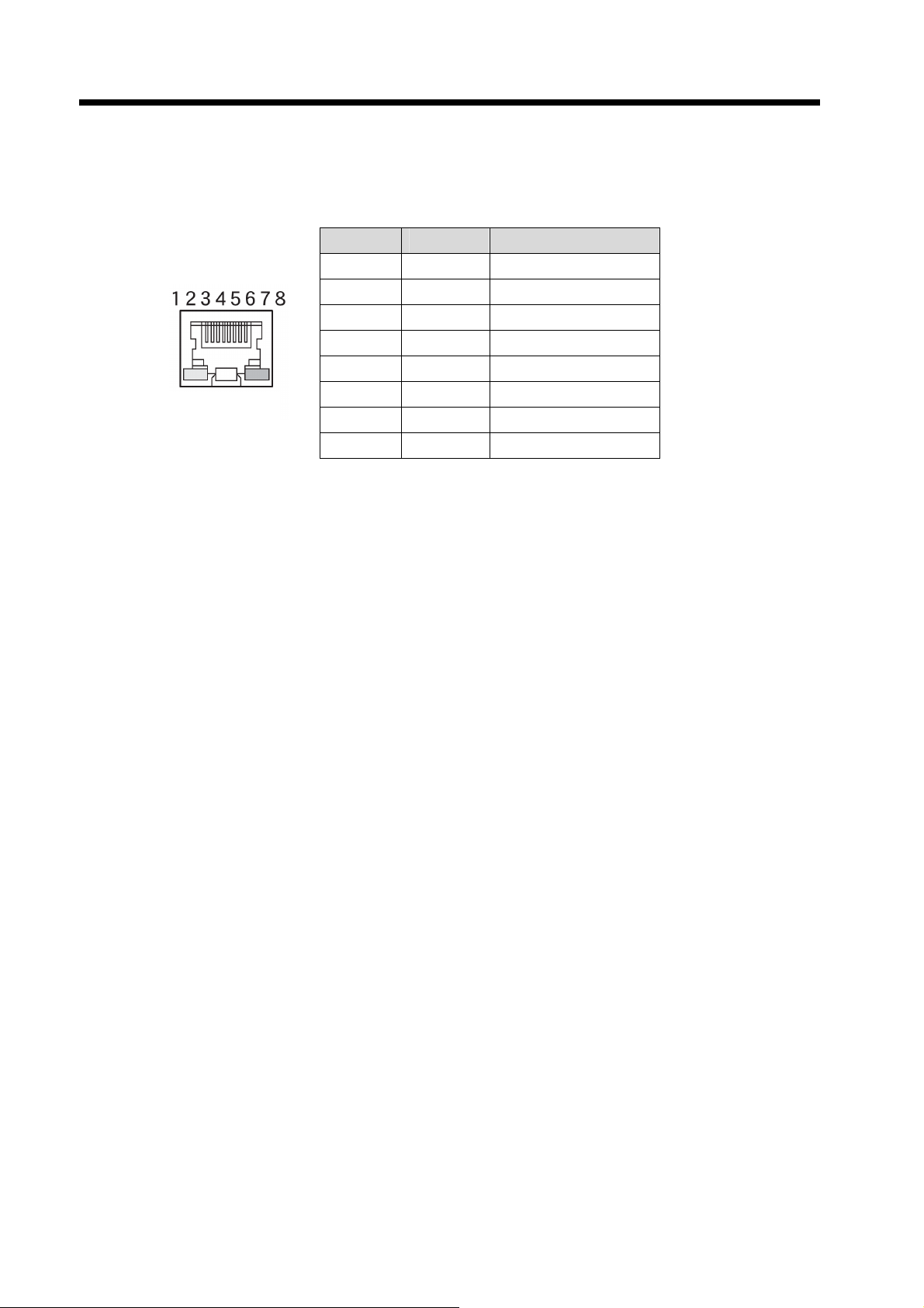
Appendix 3 Connector Pin Map
(1) Ethernet Interface : Ethernet port-1/2
Connector: 8pin modular plug
Pin No. Signal Meaning
1 TD+ Data Output+
2 TD- Data Output-
3 RD+ Data Input+
4 N.C. No Connection
5 N.C. No Connection
Pin layout
6 RD- Data Input-
7 N.C. No Connection
8 N.C. No Connection
46

Appendix
(2) RS-232C Interface : Serial port - 1/2
Connector: D-Sub 9 pin plug connector (fixed screw : 4-40 UNC)
Pin No. Signal Meaning Signal Meaning
1 N.C. No Connection N.C. No Connection
2 RD Receive Data RD Receive Data
3 SD Send Data SD Send Data
4 ER
5 GND Signal Ground GND Signal Ground
6 N.C. No Connection N.C. No Connection
7 RS Request to Send RS
8 CS Clear to Send CS
9 N.C. No Connection N.C. No Connection
Port 1
Data Terminal Ready
N.C. No Connection
Port 2
Turn back connection
(3) RS-485 Interface : Serial port - 1
Connector: D-Sub 9 pin plug connector (fixed screw : 4-40 UNC)
Pin No. Signal Meaning
1 Tx(-) Send Data (-)
2 Tx(+) Send Data (+)
3 Rx(+) Receive Data (+)
4 Rx(-) Receive Data (-)
5 GND Signal Ground
6 N.C. No Connection
7 N.C. No Connection
8 N.C. No Connection
9 N.C. No Connection
47

Appendix
(4) Digital Input/Output Connector
Pin
No.
A10 N.C. No Connection B10 N.C. No Connection
A11 N.C. No Connection B11 N.C. No Connection
A12 N.C. No Connection B12 N.C. No Connection
Signal Meaning
A1 P.S(+) Power Pin (+) B1 P.S(-) Power Pin (-)
A2 DI1(+)
A3 DI2(+)
A4 DI3(+)
A5 DI4(+)
A6 DO1(+)
A7 DO2(+)
A8 DO3(+)
A9 DO4(+)
Digital Input 1 (+)
Digital Input 2 (+)
Digital Input 3 (+)
Digital Input 4 (+)
Digital Output 1 (+)
Digital Output 2 (+)
Digital Output 3 (+)
Digital Output 4 (+)
Pin
No.
Signal Meaning
B2 DI1(-)
B3 DI2(-)
B4 DI3(-)
B5 DI4(-)
B6 DO1(-)
B7 DO2(-)
B8 DO3(-)
B9 DO4(-)
Digital Input 1 (-)
Digital Input 2 (-)
Digital Input 3 (-)
Digital Input 4 (-)
Digital Output 1 (-)
Digital Output 2 (-)
Digital Output 3 (-)
Digital Output 4 (-)
48

TOSHIBA Distributed Control Network Computer GIGABINE
ULCS2 Hardware Instruction Manual
2nd Edition February 28, 2005
Issued by
Industrial and Power Systems & Services Company
1-1, Shibaura 1-chome, Minato-ku, TOKYO, 105-8001, JAPAN
The material in this manual may be revised without notice.
©TOSHIBA Corporation 2004-2005. All Rights Reserved.
No part of this manual may be reproduced in any form without permission.

 Loading...