

Page 1
FILE NO. A04-016
TCS-NET AIR CONDITIONING
CONTROL SYSTEM
(TOUCH SCREEN CONTROLLER)
Page 2

CONTENTS
1 OUTLINE
1-1 TCS-Net Air conditioning control system outline ............................................................................................... 4
1-2 Component .......................................................................................................................................................5
1-2-1 TCS-Net Control system component ......................................................................................................5
1-2-2 Application control component ...............................................................................................................6
1-3 Basic system component ................................................................................................................................. 7
1-3-1 Apparatus component ............................................................................................................................7
1-3-2 The control system devices ................................................................................................................... 8
1-3-3 The control system devices (Procured on site).......................................................................................9
1-3-4 Software .................................................................................................................................................9
1-4 Touch screen controller function...................................................................................................................... 10
1-5 Energy monitoring and billing function ............................................................................................................. 13
1-6 Input/Output.................................................................................................................................................... 15
2 SYSTEM CONFIGURATION
2-1 Touch screen controller system configuration .................................................................................................... 18
3 INSTALLATION
3-1 Installation work flow....................................................................................................................................... 24
3-2 Setup file data preparation .............................................................................................................................. 25
3-2-1 Control wiring diagram (Connection example) ....................................................................................... 25
3-2-2 Power meter wiring diagram (Connection example) ............................................................................... 26
3-2-3 Air conditioner address table ................................................................................................................ 27
3-2-4 Schedule table ..................................................................................................................................... 29
3-3 Setup file creation ........................................................................................................................................... 30
3-3-1 Setup file creation software (Excel macro) ........................................................................................... 30
3-3-2 Setup file contents ............................................................................................................................... 31
3-4 Control system installation ..............................................................................................................................31
3-4-1 External view ....................................................................................................................................... 34
3-4-2 Installation method ............................................................................................................................... 38
3-4-3 Device specifications ........................................................................................................................... 41
3-5 Wiring ............................................................................................................................................................. 42
3-5-1 Wiring specifications ............................................................................................................................ 42
3-5-2 Wiring diagram ..................................................................................................................................... 43
3-6 Network connection ........................................................................................................................................ 52
3-7 Control system configuration........................................................................................................................... 53
4 ADDRESS SETTING
4-1 Address setting flow .......................................................................................................................................56
4-2 Definition of address ....................................................................................................................................... 57
4-3 Address setting for air conditioner ...................................................................................................................62
4-3-1 Setting for VRF system ........................................................................................................................ 62
(1) Check at main Power-ON .............................................................................................................. 63
(2) Manual setting from wired remote controller .................................................................................. 64
(3) Line (system) address setting .......................................................................................................66
(4) Power reset ...................................................................................................................................66
(5) Indoor unit address check .............................................................................................................67
(6) Trial operation ................................................................................................................................ 67
(7) Setup of relay connector and terminator ........................................................................................ 68
(8) Central control address setting ...................................................................................................... 71
(9) Trial operation for central controller (TCB-SC642TLE2) .................................................................. 73
(10) Automatic address setting (for reference) .................................................................................... 74
(11) Clearance of address .................................................................................................................. 77
(12) Confirmation of indoor unit address and position by using the remote controller .......................... 78
(13) Address change from remote controller .......................................................................................79
(14) In case of increase the address-undefined indoor units (Extension, etc.) .................................... 81
(15) Address setup example (VRF system) ........................................................................................ 82
4-3-2 Setting for 1 to 1 system ...................................................................................................................... 85
(1) Address re-setup ........................................................................................................................... 85
(2) Indoor address change example.................................................................................................... 89
4-4 Address setting for Control System devices ................................................................................................... 91
4-4-1 Address setting flow .............................................................................................................................91
4-4-2 Setting for Intelligent server ................................................................................................................. 92
4-4-3 Setting for TCS-Net relay interface .......................................................................................................93
4-4-4 Setting for Energy monitoring relay interface ........................................................................................ 94
4-4-5 Setting for Digital I/O relay interface..................................................................................................... 95
5 TRIAL OPERATION
5-1 Trial operation..................................................................................................................................................98
5-2 Air conditioning control system troubleshooting ............................................................................................ 101
5-2-1 Faults on the air conditioner ............................................................................................................... 101
5-5-2 Faults on the air conditioning control system ...................................................................................... 101
2
Page 3

1
OUTLINE
1-1 TCS-Net Air conditioning control system outline
1-2 Component
1-2-1 TCS-Net control system component
1-2-2 Application control component
1-3 Basic system component
1-3-1 Apparatus component
1-3-2 The control system devices
1-3-3 The control system devices (Procured on site)
1-3-4 Software
1-4 Touch screen controller function
1-5 Energy monitoring and billing function
1-6 Input/Output
3
Page 4
1-1 TCS-Net Air conditioning control system outline
The TCS-Net Air conditioning control system achieves an easy-to-operate central air conditioning control
with the LCD Touch Screen Controller integrating advanced functions. The system allows operation status
monitoring, operation control, scheduled operation and error code display of up to 512 indoor units with
one controller. It is also equipped with functions for energy monitoring and billing (Individual indoor units)
and for operation control using external input/output signals.
Operation status monitoring
Monitors operation status of all air conditioners collectively.
Operation control
Controls operation of devices with the LCD touch panel. Allows detailed operation settings, such as
collective operation of an entire building or each block/tenant/area, as well as individual operation of each
indoor unit.
Operation schedule
Allows detailed operation schedule settings for each area.
Error code display
Displays failure information, location, time when the failure occurs and displays fault log information.
Energy monitoring and billing
Determines power usage for each indoor unit and outputs the calculation results as daily/monthly reports.
I/O function
Provides operation control using external input signals and outputs emergency signals to external
devices.
4
Page 5
SMMS
SHRM
Master remote controller
Super Digital Inverter
Digital Inverter
TCS-Net Interface
BMS-IFLSV1E
BMS-LSV2E
Intelligent server
HUB
Power meter
I/F
BMS-IFWH3E
Energy meter
relay interface
PC
I/F
Digita l/O Relay
Interface
BMS-IFDD01E
Side remote controller
"1:1 model"
TCB-PCNT30TLE
connection interface
BMS-TP0640ACE
BMS-TP0640PWE
BMS-TP5120ACE
1-2 Component
1-2-1 TCS-Net control system component
BMS-TP5120PWE
PC for Energy monitoring and billing
Touch screen controller
5
Page 6
SMMS
SHRM
Super Digital Inverter
Digital Inverter
"1:1 model"
TCB-PCNT30TLE2
connection interface
TCB-IFCB-4E2
Remote location
ON/OFF control box
Network adapter
TCB-PCNT20E
AI-NETWORK
AI-NET central
control devices
Wireless
remote
controller
Sub-remote
controller
RBC-AS21E2
Wired remote controller
RBC-AMT31E
Weekly timer
RBC-EXW21E2
TCS-Net Interface
BMS-IFLSV1E
BMS-LSV2E
Intelligent
server
HUB
4-4ø hole
5
PJ17
8
ICI
5
MS10MS
TCB-PCOM1
TCB-PCOM1E
NCC-1212
41
OFFON
TOSHIBA
71
61
K100
COM COMON
OFF
T82
T81
OFF
ON
OPERATION/
75
85
Terminal
Terminal
Screw M3 6
Screw M4 8
Power peak-cut
control board
TCB-PCDM2E
4-4ø hole
41
PJ17
ICI
5
8
10
41
TCB-PCMO1
TCB-PCMO1E
55.5
45.5
D2
COM
TOSHIBA
NCC-1214
TB1
HEAT
COM COOL
50
60
Screw M3 6
Terminal
External master
ON/OFF board
TCB-PCMO2E
I/F
BMS-IFWH3E
Power
meter
I/F
Energy meter
relay interface
Digita l/O Relay Interface
BMS-IFDD01E
ON/OFF command
Alarm status output
Central remote
controller
Master ON/OFF signal
Batch drive, error output
Master ON/OFF signal
Power peak-cut control signal
Operation control command
Operation status output
Master remote controller
Side remote controller
TCB-SC642TLE2
Air-conditioning
Weekly timer
RBC-EXW21E2
Management on site
PC
PC for Energy
monitoring and
billing
1-2-2 Application control component
BMS-TP0640ACE
BMS-TP0640PWE
BMS-TP5120ACE
BMS-TP5120PWE
Touch screen
controller
6
Page 7
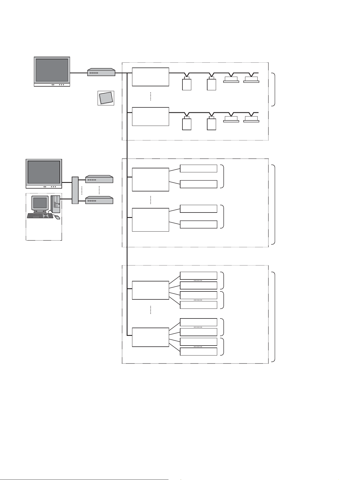
1-3 Basic system component
1-3-1 Apparatus component
Compact
Flash
Set up files
Touch Screen Controller
(BMS-TP0640 / 5120)
PC for Energy Monitoring
and billimg
(Procured on site)
Ethernet
Switching HUB
(Procured on site)
InteIligent Server
(BMS-LSV2E)
Compact
Flash
Intelligent server
Software
(BMS-STCC01E)
RS- 485
TCS- NET
Relay I /F
(BMS-IFLSV1E)
TCS- NET
Relay I /F
(BMS-IFLSV1E)
Energy
Monitoring
Relay I /F
(BMS-IFWH3E)
Energy
Monitoring
Relay I /F
(BMS-IFWH3E)
Main BUS
Main BUS
Main BUS
Power meter 1
Power meter 8
Power meter 1
Power meter 8
Input 1
(Procured on site)
(Procured on site)
(Procured on site)
(Procured on site)
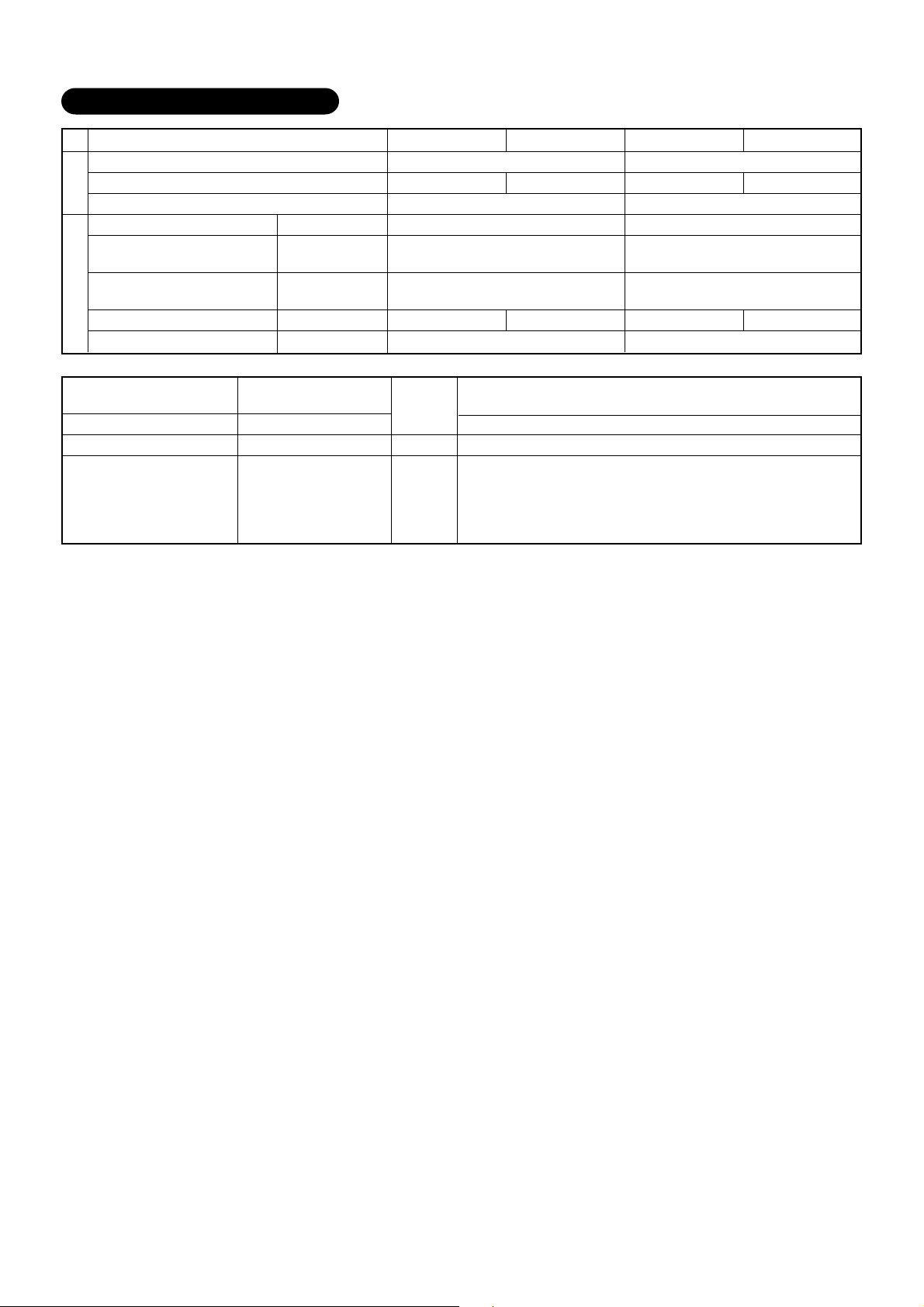
System Configuration Table
Monitoring/Control/Scheduling/Fault code display
Energy monitoring and billing
Indoor units connected
Function
Digital I/O
Touch Screen Controller
Intelligent Server
Intelligent Server Software
TCS-NET Relay I/F
Energy Monitoring Relay I/F
Devices
Digital I/O Relay I/F
PC (for Energy monitoring
and billing)
Switching HUB
BMS-LSV2E
BMS-STCC01E
BMS-IFLSV1E
BMS-IFWH3E
BMS-IFDD01E
Procured on site
Procured on site
Digital I/O
Relay I /F
(BMS-IFDD01E)
Digital I/O
Relay I /F
(BMS-IFDD01E)
Input 8
Output 1
Output 4
Input 1
Input 8
Output 1
Output 4
××××
××
Max. 64 units Max. 64 units Max. 512 units Max. 512 units
×× × ×
BMS-TP0640ACE BMS-TP0640PWE BMS-TP5120ACE BMS-TP5120PWE
Ч ЧЧЧЧЧЧЧ
Ч ЧЧЧЧЧЧЧ
Ч ЧЧЧЧЧЧЧ
×× × ×
×× × ×
×× × ×
×(*
)
×(*
)
×(*
)
×(*
)
×(*
)
×(*
)
×(*
)
×(*
)
(*) A Switching HUB is required when using two or more Intelligent servers or when connecting to a PC for Energy Monitoring
and billing.
7
Page 8
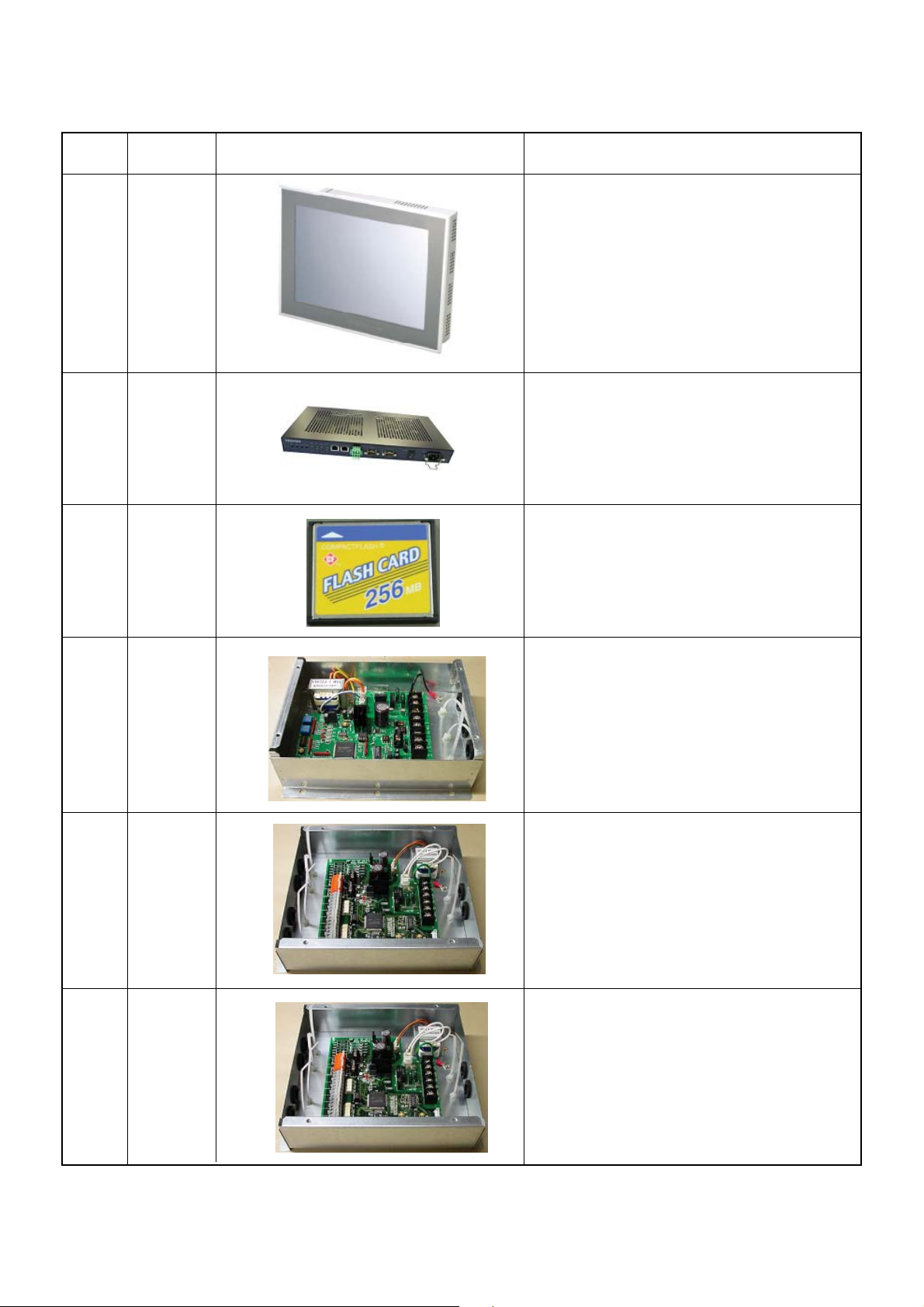
1-3-2 The control system devices
Name
Touch Screen Controller
Intelligent Server
Intelligent Server
Model
name
BMS-TP0640ACE
BMS-TP5120ACE
Software
BMS-TP0640PWE
BMS-LSV2E
BMS-STCC01E
BMS-TP5120PWE
Appearance Performance
Operation monitoring
Operation control
Operation schedule
Error code display
Fire alarm input
Energy monitoring data saving to CF card
Data collection
Data collection software
(This software is used for the Intelligent server)
Interface
TCS-Net Relay
Relay Interface
Energy Monitoring
Interface
Digital I/O Relay
BMS-IFLSV1E
BMS-IFWH3E
BMS-IFDD01E
Protocol transformation
Main BUS to RS-485
Power meter interface
Input and output interface
Fire alarm input
Key input
Error output
8
Page 9

1-3-3 The control system devices (Procured on site)
Name
Mesurement of power consumption.
Output data by pulse signal
Power meter
Network with
Touch screen controller
Intelligent server
Energy monitoring PC
Ethernet wire
Switching HUB and
Energy monitoring calculation
Electricity billing calculation
Monthly report creation
and billing
Performance Specification
Pulse output type
Pulse generator constants: 1kWh/pulse or 10kWh/pulse
Pulse duration: 50 - 1000 ms
Output terminal: ON/OFF contactor
HUB:
10BASE-T compliant (*)
Number of ports: as required
Ethernet wire: Category5 UTP straight cable (with HUB)
Category5 UTP cross cable (without HUB)
Microsoft Excel is required for the energy monitoring and
billing function
OS: Windows 2000 or newer
Excel: Excel 2000 or newer
PC for energy monitoring
* 100BASE-T compliant HUB is required when using 5 or more servers, or 2 or more controllers.
1-3-4 Software
Name
Monthly report
creation software
Monthly report creation
Power distribution calculation
Billing calculation
Daily sum report creation
Performance Note
This software is provided on CD-ROM
9
Page 10
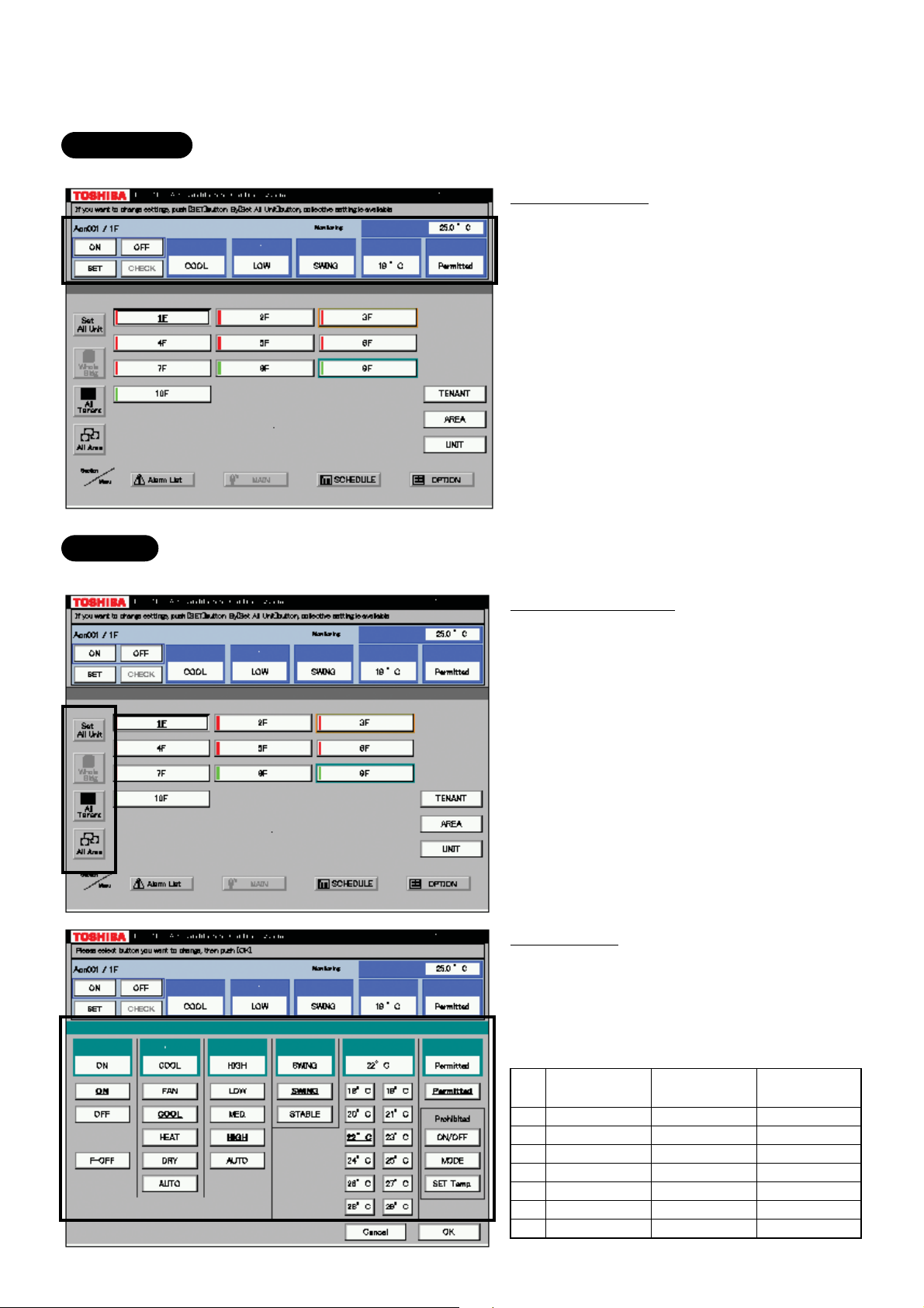
1-4 Touch screen controller function
Monitoring
All Indoor unit conditions can be monitored by the controller.
Monitoring Items
Mode
FAN mode
Louver setting
Set Temperature
Inlet air temperature
R/C control prohibition
Control
All Indoor unit operations can be controled within the user's selected division.
Controlable division
Whole building
All tenant
All area
Unit
Setting Items
Mode
Fan mode
Louver setting
Set temperature
Inlet air temperature
R/C control prohibition (7 combinations)
ON/OFF
prohibition
1
2
3
4
5
6
7
×
–
–
×
×
–
×
MODE
prohibition
–
×
–
×
–
×
×
SET TEMP
prohibition
–
–
×
–
×
×
×
10
Page 11
Management zone categories
All Block Tenant Area
Building A 1-1 (header unit)
1F
Tenant A
Shop A
RC
Group/Unit
101
(line address + indoor unit address)
Indoor Unit
1-2 (follower unit)
102
1-3 (header unit)
1-4 (follower unit)
103
1-5 (header unit)
1-6 (follower unit)
1-7 (follower unit)
Office A
104
1-8 (header unit)
1-9 (follower unit)
Tenant B
Shop B
105
2-1 (header unit)
2-2 (follower unit)
Tenant C
Office B
Shop C
106
107
108
2-3 (header unit)
2-4 (header unit)
2-5 (header unit)
2-6 (follower unit)
2-7 (follower unit)
2-8 (follower unit)
109
110
2-9 (follower unit)
3-1 (header unit)
Shared
space
Office C
1F outdoor
air conditioner
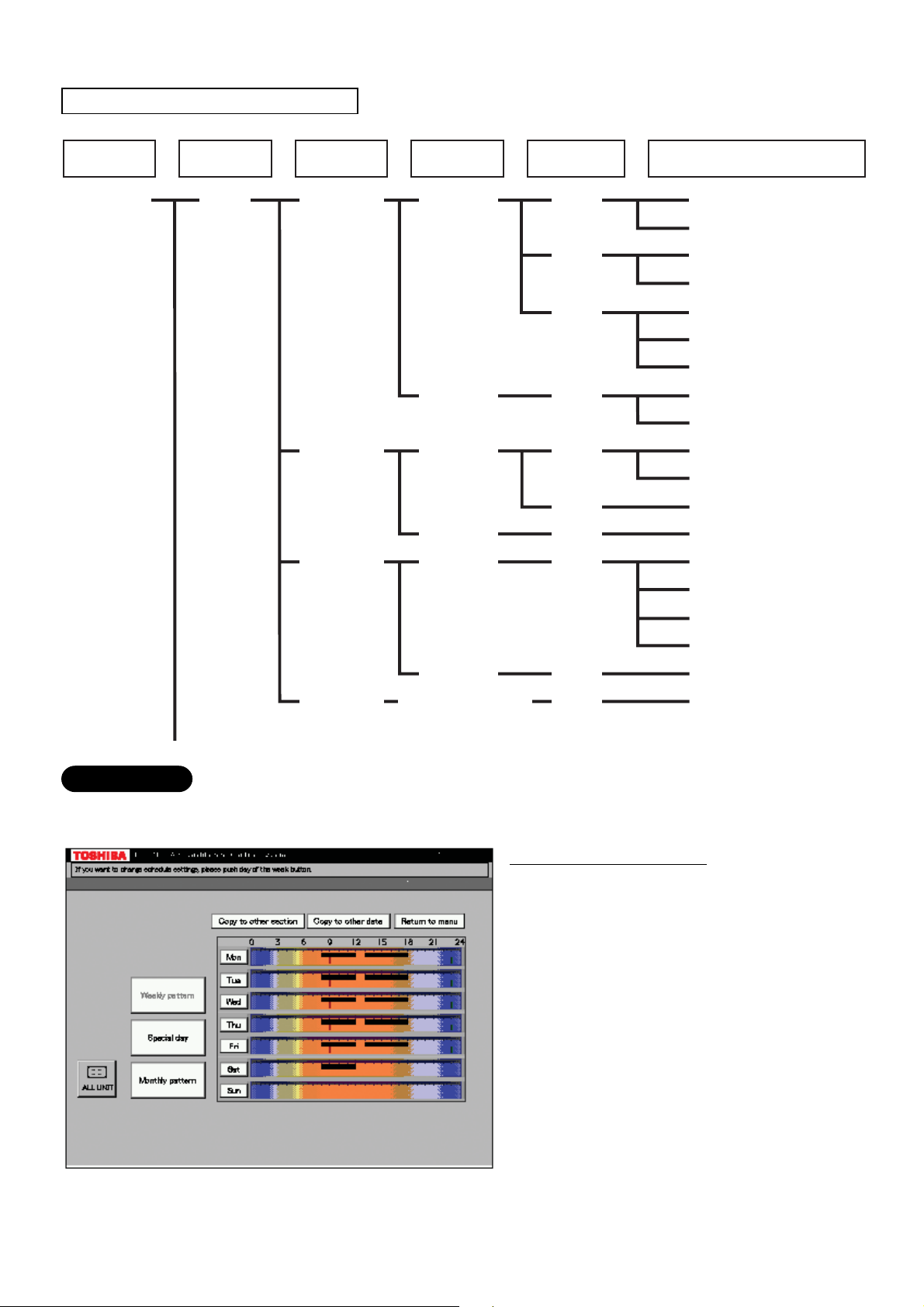
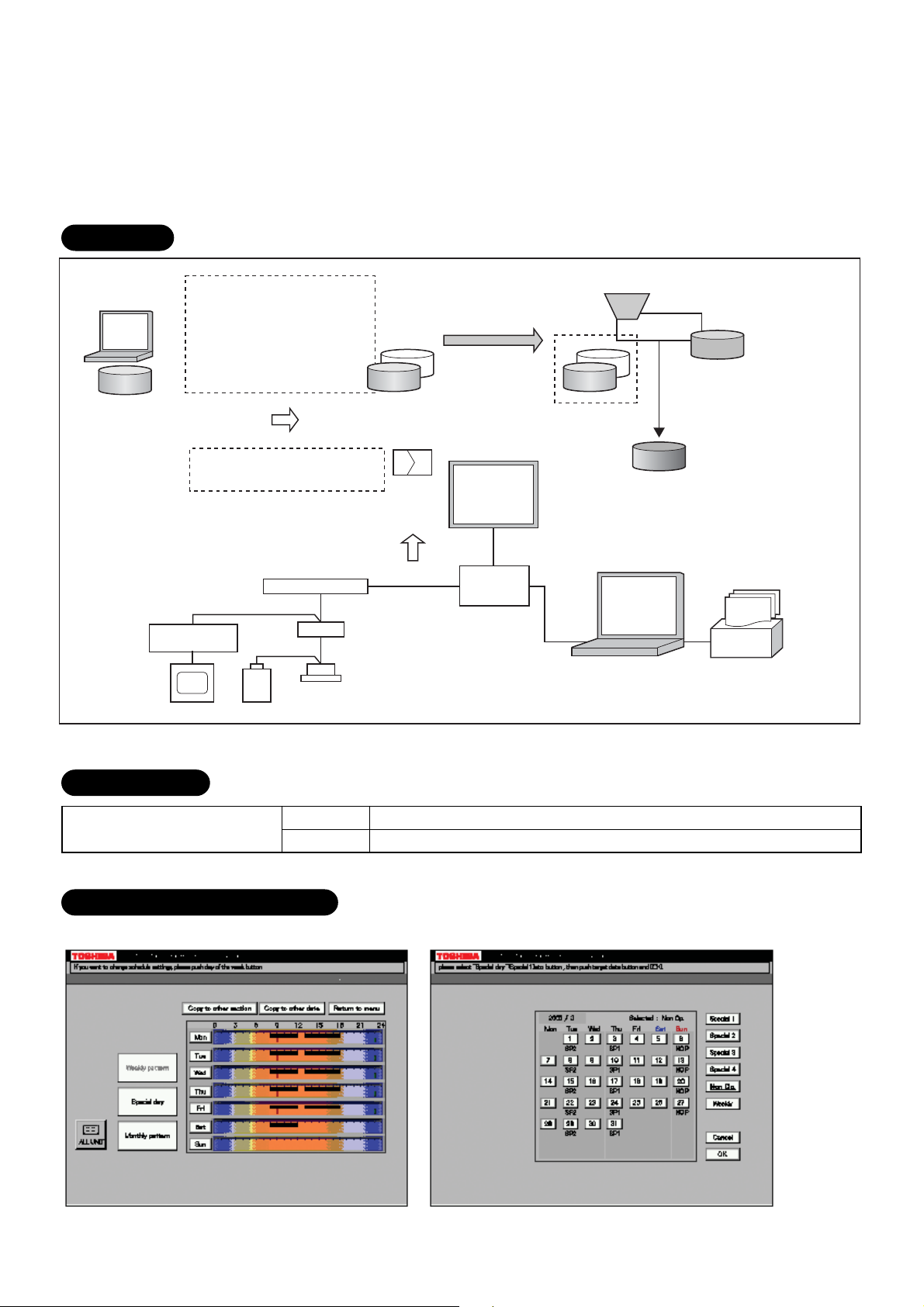
Scheduling
A basic operation schedule pattern is determined by setting the weekly and monthly operation schedules.
The schedules can be set for each area.
Weekly schedule setting
Up to 20 patterns a day (including ON and
OFF) can be set.
11
Page 12
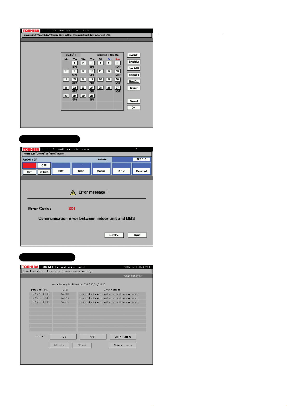
Error code display
Monthly schedule setting
Schedule patterns except for weekly schedule
patterns can be set as special-days.
Up to four special-day patterns can be set.
Non-operation dates can also be set.
When an error occurs on a device, an error
code is displayed.
Fault log display
12
Page 13
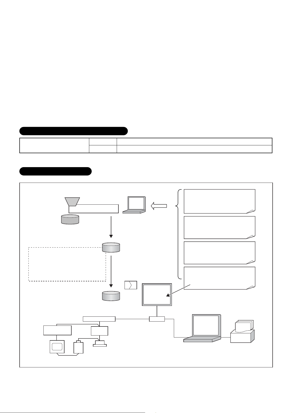
1-5 Energy monitoring and billing function
Distributes the total power consumption for each indoor unit according to the billing schedule that has been
set by the Touch Screen Controller. The system setup file and the operation result file saved on the CF card
of the Touch Screen Controller are uploaded onto the PC. The PC calculates the power distribution result
using the dedicated report creation software (Excel macro) to create spreadsheets and monthly reports.
Data flow
Setup file creation
software
Setup file
monitoring I/F
Power meter
Setup file
• Tenant name, etc.
• Air conditioner information, etc.
• Setting values for energy
monitoring and billing
Air conditioner specific
characteristic values
Tenant names for reports
Air conditioner operation result
Power meter pulse counter value
Intelligent Server
RS-485
Energy
IF
Air conditioner
Main BUS
Monthly meter-read
file Setup file
Records to
CF card
Every
15 min
Ethernet
File transfer (FTP)
Touch Screen
Controller
HUB
(procured on
locally)
Energy
Ethernet
monitoring
and billing
software
PC (procured on site)
Report creation software
(Excel macro)
Excel
Default data file
Monthly report, spreadsheet
(Excel file)
Printer
Printer for monthly reports
(procured on site)
Specification
PC operating system
OS
Excel
A PC and printer for energy monitoring and billing should be procured on site.
Windows 2000 or newer
Excel 2000 or newer is required separately.
Electricity billing schedule
Touch Screen Controller sets a billing schedule for monthly reports.
13
Page 14
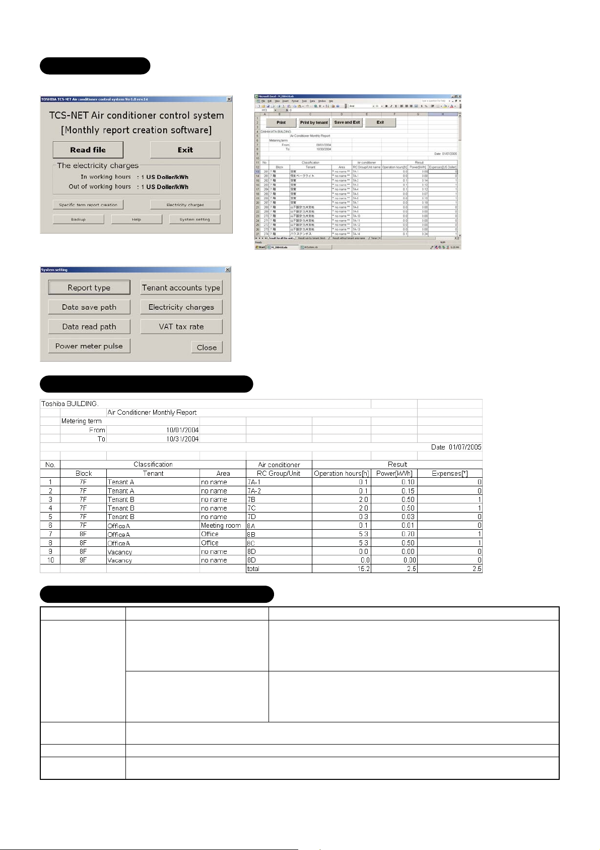
Monthly Report
The report creation software creates monthly reports in an Excel file format.
Monthly report printout example
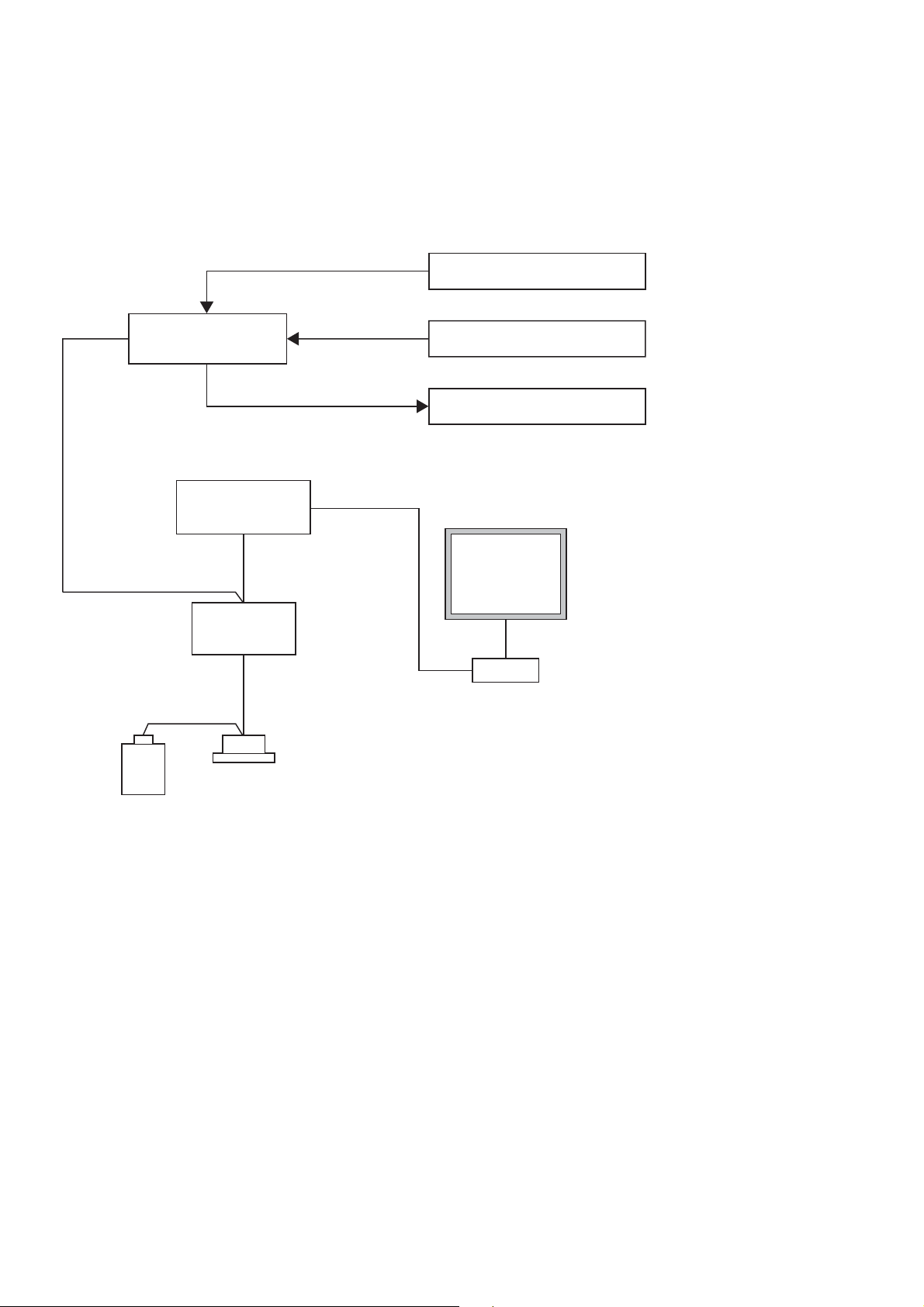
Report creation software functions
Function
Monthly report
creation
Power distribution
calculation
Billing calculation
Daily sum report
creation
Creates operation result reports
for each indoor unit group.
These can be totalled by the
touch screen controller based
upon the setup files.
Creates 4 types of spreadsheets
for monthly reporting.
Calculates power distribution for each indoor unit group
Calculates expenses for each indoor unit group
Totals daily reports in specified range to create a monthly report.
Description
Remarks
Operation result report type:
• Display operation hours
• Display operation hours, display by In/Out working hours
• Display operation hours/consumption/billing
•
Display operation hours/consumption/billing, display by In/Out working hours
Spreadsheet type:
• Operation result for all the units
• Operation result without tenant, Area name
• Operation result sum by tenant, block
• Accounts sum by tenant
14
Page 15
1-6 Input/Output
This system controls the air conditioners by interlocking them with electric lock signals and fire alarm
signals and can transmit air conditioner emergency signals to other devices.
Fire alarm input
RS- 485
Digital I/O
Relay I/F
Intelligent
Server
TCS-Net
Relay I/F
Air conditioner
Main BUS
Ethernet
Door-lock input
Error output
Touch Screen
Controller
HUB
Ethernet
• Controls Air conditioners by
interlocking with input signals.
• Outputs Air conditioner error
to external devices.
15
Page 16

16
Page 17

2
SYSTEM CONFIGURATION
2-1 Touch screen controller system configuration
17
Page 18
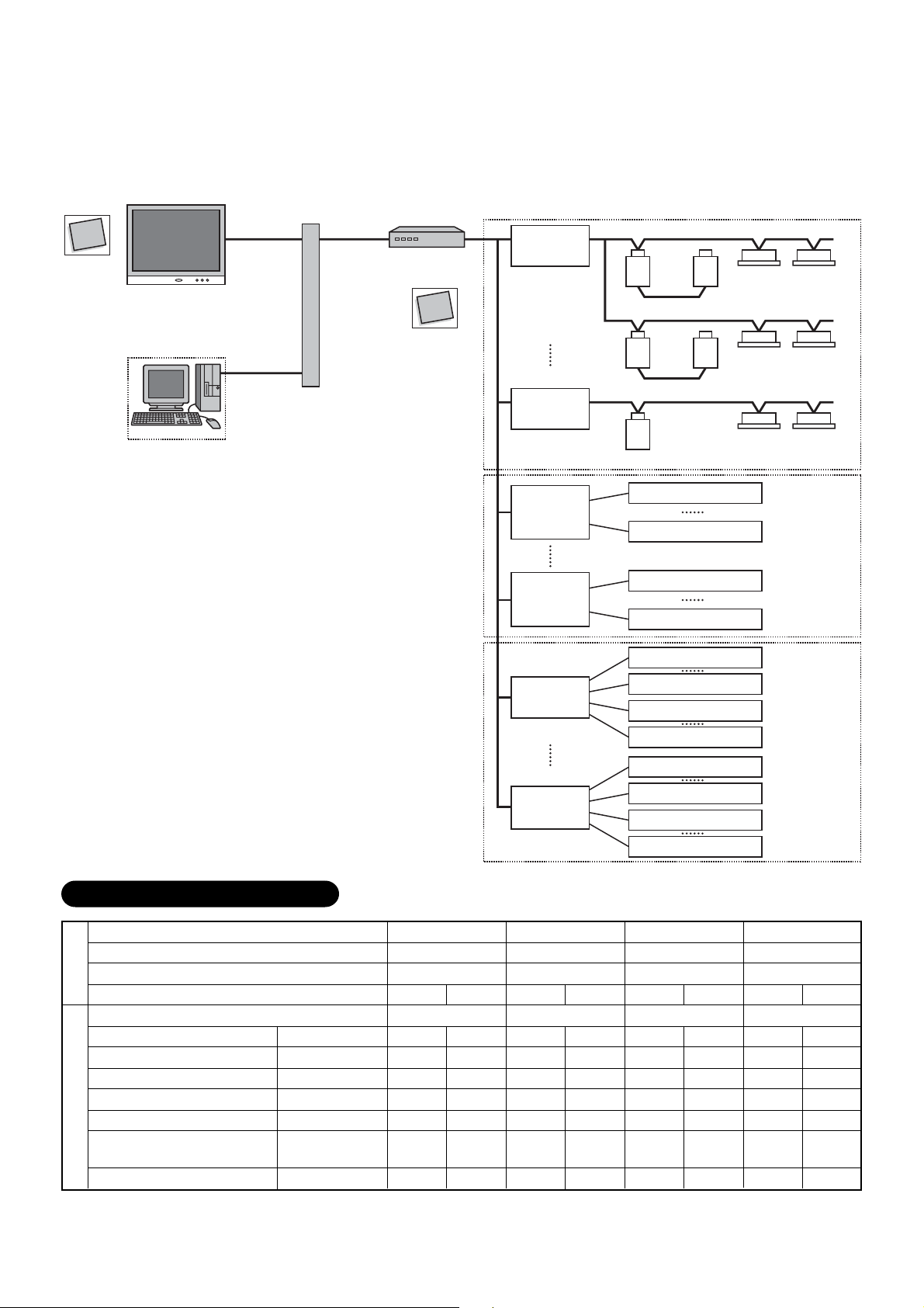
2-1 Touch screen controller system configuration
RS-485
Ethernet
Touch Screen Controller
(BMS-TP0640/5120)
InteIligent Server
(BMS-LSV2E)
Compact
Flash
TCS-NET
Relay I/F
(BMS-IFLSV1E)
Main Bus
Max. 64 air conditioners
per relay I/F
Max. 512 indoor
units (64 units x 8)
per Intelligent
Server
Intelligent Server Software
(BMS-STCC01E)
(*) A Switching HUB is required when using
two or more Intelligent Servers or when
connecting a PC for energy monitoring
and billing.
Switching HUB
PC for Energy
Monitoring and
billing
TCS-NET
Relay I/F
(BMS-IFLSV1E)
MAX 8 per
Intelligent server
Energy
Monitoring
Relay I/F
(BMS-IFWH3E)
Energy
Monitoring
Relay I/F
(BMS-IFWH3E)
MAX 4 per
Intelligent server
Main Bus
Max. 64 air conditioners
per relay I/F
Power meter 1
(with pulse generator)
Power meter 8
(with pulse generator)
Power meter 1
(with pulse generator)
Power meter 8
(with pulse generator)
Max. 8 power
meters per relay I/F
Max. 32 (8 x 4)
power meters per
Intelligent Server
Max. 8 power
meters per relay I/F
Digital I/O
Relay I/F
(BMS-IFDD01E)
Digital I/O
Relay I/F
(BMS-IFDD01E)
MAX 4 per
Intelligent server
Input contact 1
Input contact 8
Device 1
Device 4
Input contact 1
Input contact 8
Device 1
Device 4
Max. 8 input
contacts per
relay I/F
Max. 4 devices
per relay I/F
Max. 8 input
contacts per
relay I/F
Max. 4 devices
per relay I/F
Max. 32 (8 x 4)
digital inputs per
Intelligent Server
Max. 16 (4 x 4)
digital outputs
per Intelligent
Server
18
Page 19
System Configuration Table
...
(×
available –
...
not available)
Touch Screen Controller
Air conditioning monitoring/control
Energy monitoring and billing
Indoor units connected
Function
Intelligent Server
Intelligent Server Software
TCS-NET Relay I/F
Component
Energy Monitoring Relay I/F
Digital I/O Relay I/F
Switching HUB
Ethernet wire
PC
Power meter
*1:The number of ethernet wires and the number of switching HUB ports vary with the number of Intelligent Servers
connected.
*2:100 BASE-T compliant is required when using 5 or more servers, or 2 or more controllers.
*3:The number of power meters vary with power meter specifications.
• Two or more refirgerant systems can be connected to one power meter.
• For heat recovery VRF (SHRM) and “Super digital inverter”, “Digital inverter”, it is necessary to install the power meter
independently.
• All power meters connected to the same controller must be set to the same pulse generator constants.
BMS-LSV2E
BMS-STCC01E
BMS-IFLSV1E
BMS-IFWH3E
BMS-IFDD01E
Procured on site
Procured on site
Procured on site
Procured on site
BMS-TP0640ACE BMS-TP0640PWE BMS-TP5120ACE BMS-TP5120PWE
×
–×
Max. 64 units
1 unit
1 unit
Max. 8 units
– Max. 4 units
Max. 4 units
Comply with 10BASE-T
1
*
Number of ports: As required
Category 5 UTP straight wire
OS: Windows 2000 or newer, Excel 2000 or newer
Pulse output type
Pulse generator constants:
3
1 kWh/pulse or 10 kWh/pulse
*
Pulse duration: 50 - 1000 ms
Output terminal: ON/OFF contactor
2
*
–×
1 unit per Intelligent Server
(max. 4 units in total)
Up to 8 units per Intelligent Server
(max. 32 units in total)
– Max. 4 units
×
Max. 512 units
Max. 4 units
Max. 4 units
19
Page 20

System configuration examples
The following lists detail the required component devices for each category.
1. Without energy monitoring
(A) Up to 64 indoor units
Device
Touch Screen Controller
Intelligent Server
Intelligent Server Software
TCS-NET Relay Interface
Digital I/O Relay Interface
Ethernet wire
(B) Up to 512 indoor units
Model
BMS-TP0640ACE
BMS-LSV2E
BMS-STCC01E
BMS-IFLSV1E
BMS-IFDD01E
Procured on site
Quantity
1
1
1
Max. 8
Max. 4
1
*
Up to 8 units per Intelligent Server
Category5 UTP cross cable
Remarks
Device
Touch Screen Controller
Intelligent Server
Intelligent Server Software
TCS-NET Relay Interface
Digital I/O Relay Interface
Ethernet wire
Switching HUB
2. With energy monitoring
(A) Up to 64 indoor units
Device
Touch Screen Controller
Intelligent Server
Intelligent Server Software
TCS-NET Relay Interface
Energy Monitoring Relay
Interface
Digital I/O Relay Interface
Ethernet wire
Switching HUB
PC
Power meter
Model
BMS-TP5120ACE
BMS-LSV2E
BMS-STCC01E
BMS-IFLSV1E
BMS-IFDD01E
Procured on site
Procured on site
Model
BMS-TP0640PWE
BMS-LSV2E
BMS-STCC01E
BMS-IFLSV1E
BMS-IFWH3E
BMS-IFDD01E
Procured on site
Procured on site
Procured on site
Procured on site
Quantity
1
Max. 4
Max. 4
Max. 32*
Max. 16*
1
*
1
Quantity
1
1
1
Max. 8
Max. 4
Max. 4
1
*
1
1
5
*
Remarks
Same quantity as Intelligent Server
required
2
*2 Up to 8 units per Intelligent Server
3
*3 Up to 4 units per Intelligent Server
Category5 UTP straight cable
10 BASE-T compliant *
4
number of ports: As required
Remarks
Up to 8 units per Intelligent Server
Category5 UTP straight cable
10 BASE-T compliant *
4
number of ports: As required
OS: Windows 2000 or newer
Excel: Excel 2000 or newer
Pulse output type
Pulse generator constants:
1kWh/pulse or 10kWh/pulse
Pulse duration: 50 - 1000 ms
Output terminal: ON/OFF contactor
20
Page 21

(B) Up to 512 indoor units
Device
Touch Screen Controller
Intelligent Server
Intelligent Server Software
TCS-NET Relay Interface
Energy Monitoring Relay
Interface
Digital I/O Relay Interface
Ethernet wire
Switching HUB
PC
Model
BMS-TP5120PWE
BMS-LSV2E
BMS-STCC01E
BMS-IFLSV1E
BMS-IFWH3E
BMS-IFDD01E
Procured on site
Procured on site
Procured on site
Quantity
1
Max. 4
Max. 4
Max. 32*
Max. 16*
Max. 16*
1
*
1
1
Same quantity as Intelligent Server
required
2
*2 Up to 8 units per Intelligent Server
*3 Up to 4 units per Intelligent Server
3
3
*3 Up to 4 units per Intelligent Server
Category5 UTP straight cable
10 BASE-T compliant *
number of ports: As required
OS: Windows 2000 or newer
Excel: Excel 2000 or newer
Remarks
4
Pulse output type
Pulse generator constants:
Power meter
Procured on site
5
*
1kWh/pulse or 10kWh/pulse
Pulse duration: 50 - 1000 ms
Output terminal: ON/OFFcontactor
*1 The number of ethernet wires and the number of switching HUB ports vary with the number of Intelligent servers
connected.
*4 100BASE-T compliant HUB is required when using 5 or more servers, or 2 or more controllers.
*5 The number of power meters vary with power meter specifications.
• Two or more refirgerant systems can be connected to one power meter.
• For heat recovery VRF (SHRM) and “Super digital inverter”, “Digital inverter”, it is necessary to install the power meter
independently.
• All power meters connected to the same controller must be set to the same pulse generator constants.
21
Page 22

22
Page 23

3
INSTALLATION
3-1 Installation work flow
3-2 Setup file data preparation
3-2-1 Control wiring diagram (Connection example)
3-2-2 Power meter wiring diagram (Connection example)
3-2-3
3-2-4 Schedule table
3-3 Setup file creation
3-3-1 Setup file creation software (Excel macro)
3-3-2 Setup file contents
3-4 Control system Installation
3-4-1 External view
3-4-2 Installation method
3-4-3 Device specifications
3-5 Wiring
3-5-1 Wiring specifications
3-5-2 Wiring diagram
3-6 Network connection
3-7 Control system configuration
Air conditioner address table
23
Page 24
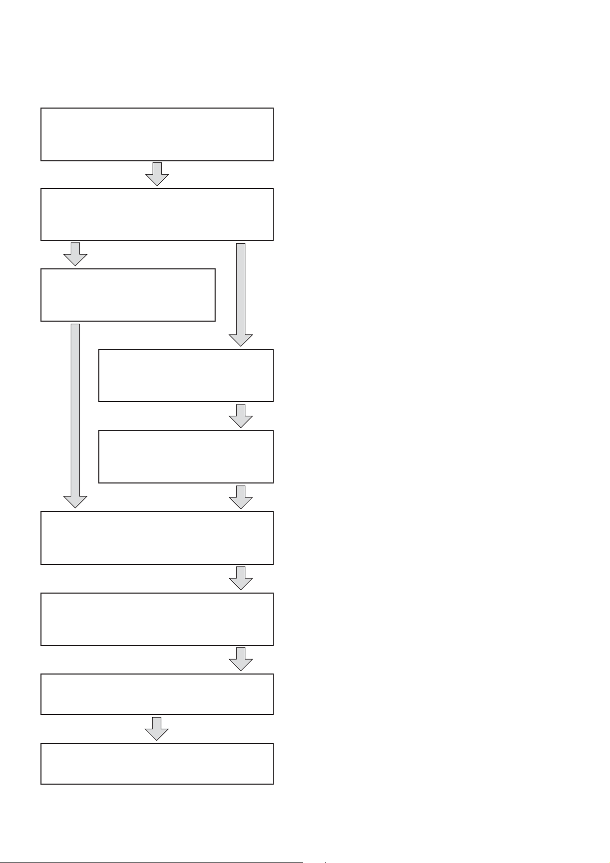
3-1 Installation work flow
Work flow
0. System planning
1. Setup file data preparation
2. Setup file creation
3. On site installation
(Construction work)
Contents Reference No.
Air conditioner equipment
selection
Control system device selection
System wiring diagram
Power meter wiring diagram
Address list
Schedule list
Create setup files by excel macro
software
Control system installation
Chapter. 2
3-2
3-3
3-4
4. On site installation
(Wiring)
5. On site installation
(Control system configuration)
6. On site installation
(Address setting)
7. Trial operation and adjustment
Wiring power cable/
communication line
Network connection
Energy monitoring PC
configuration
Intellignet server configuration
Setup file installation
Air conditioner address setting
Control system device address
setting
3-5
3-6
3-7
Chapter. 4
Chapter. 5
8. Commissioning
24
Page 25
3-2 Setup file data preparation
Before starting the installation, prepare the materials for creating the setting files.
• Control wiring diagram
• Power meter wiring diagram
• Air conditioner address table
• Schedule table
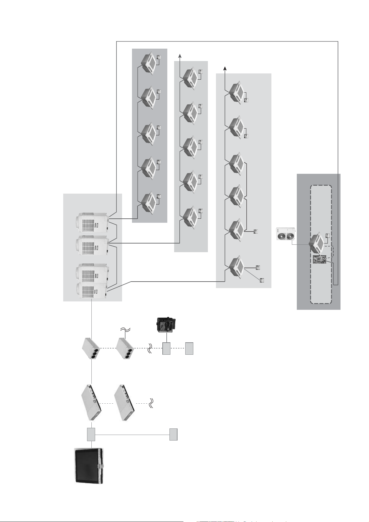
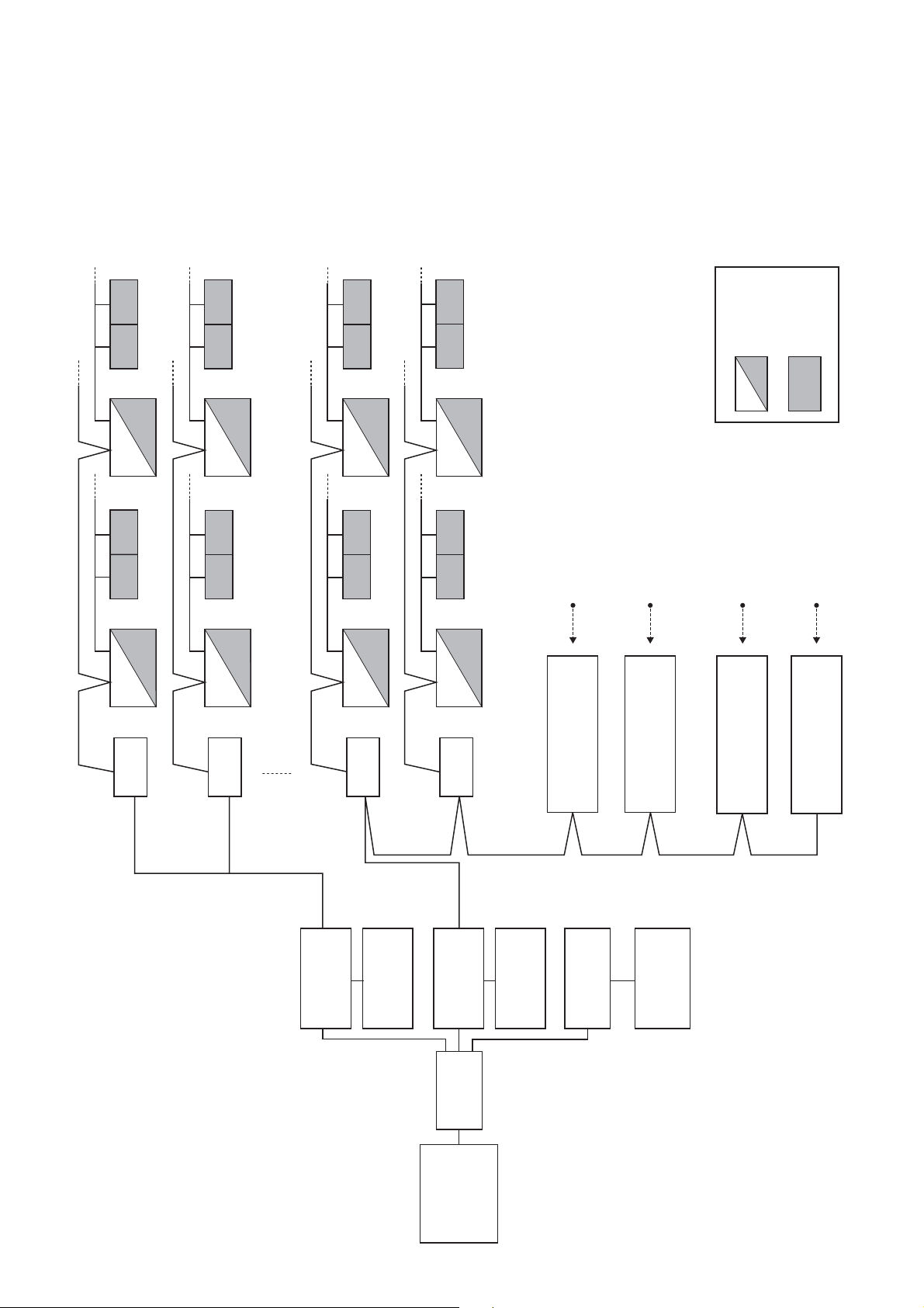
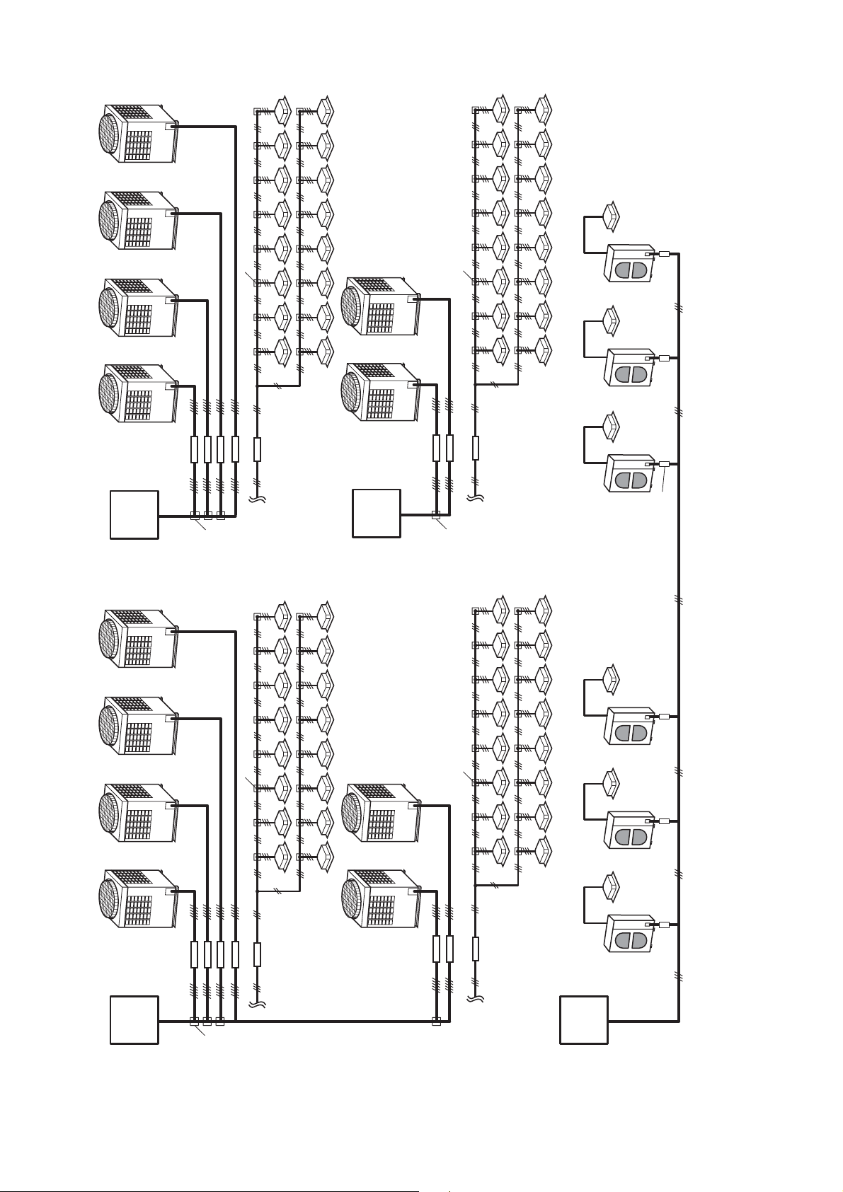
3-2-1 Control wiring diagram (Connection example)
U1,U2
Main BUS
U3,U4
U1,U2 U1,U2 U1,U2 U1,U2
U3,U4
BMS-
IFLSV1E
U1,U2 U1,U2
U3,U4
U1,U2 U1,U2
U3,U4
BMS-
IFLSV1E
U1,U2 U1,U2
U3,U4
U1,U2
U1,U2
U3,U4
BMS-
IFLSV1E
U1,U2
U3,U4
U1,U2
U1,U2
U3,U4
BMS-
IFLSV1E
8 door-lock control signal inputs
BMS-IFDD01E
Relay Interface
Digital Input/Output
8 fire alarm inputs
BMS-IFDD01E
Relay Interface
Digital Input/Output
Outdoor unit
8 power meter inputs
BMS-IFWH3E
Relay Interface
Energy Monitoring
Indoor unit
8 power meter inputs
Relay Interface
Energy Monitoring
BMS-IFWH3E
16th floor
15th floor
TCS-NET Relay Interface
TCS-NET Relay Interface
2nd floor
9th-16th
floor
Server
Intelligent
BMS-LSV2E
1st floor
TCS-NET Relay Interface
software
BMS-STCC01E
Intelligent server
TCS-NET Relay Interface
1st-8th
Server
Intelligent
BMS-LSV2E
HUB
Switching
Touch Screen
Controller
25
floor
software
BMS-STCC01E
Intelligent server
PC for creating
monthly reports
Printer
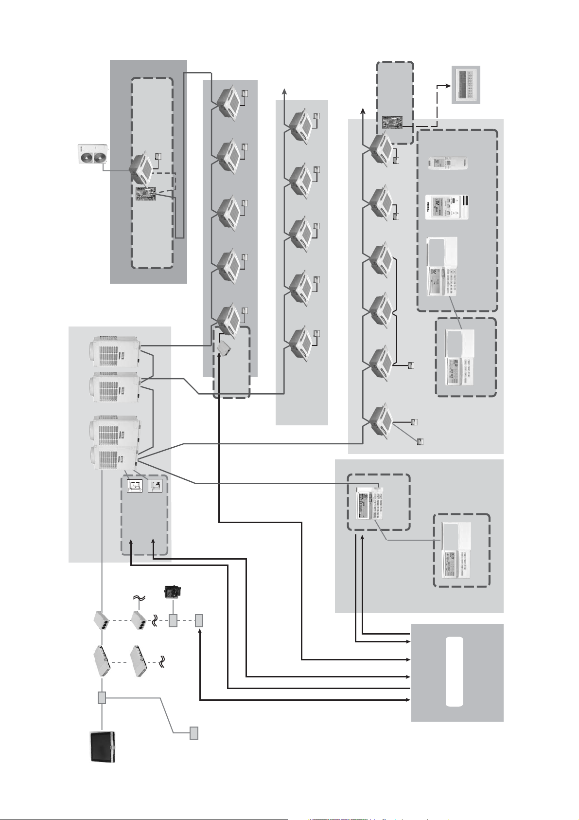
Page 26
Isolator
Isolator
SMMS
Power meter No.2
Isolator
Isolator
Power meter No.3
SHRM
Isolator
Isolator
Isolator
” it is necessary to install the power meter independently.
2
*1: Super digital inverter
” “DI*
1
*2: Digital inverter
Power meter No.1
3-2-2 Power meter wiring diagram (Connection example)
SMMS
Isolator
SMMS
26
SDI SDI DI DI DI
SDI
Power meter No.4
• Two or more refirgerant systems can be connected to one power meter.
• For heat recovery VRF (SHRM) and “SDI*
• All power meters connected to the same controller must be set to the same pulse generator constants.
Page 27
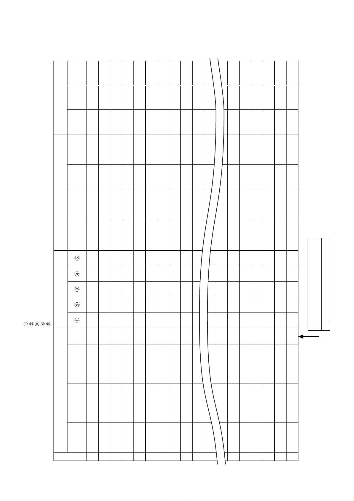
3-2-3 Air conditioner address table
No.
Fire alarm
No.
Key input
Power meter No. and
Input/Output data No.
Power
meter No.
unit
R.C. group/
Area
name
name
Tenant
Block
Address Information Display name
Intelligent Server address
TCS-NET relay I/F address
Line address
Indoor unit address
Group address
Header
Indoor unit
Air Conditioner List
Outdoor unit
name
unit
model name
model name
Header indoor unit of group control.
Indoor unit on individual control.
Follower indoor unit of group control.
1
0
system
Outdoor
refrigerant
• Building name:
1
2
3
4
5
6
7
8
9
10
11
12
15
16
17
18
19
20
27
Page 28
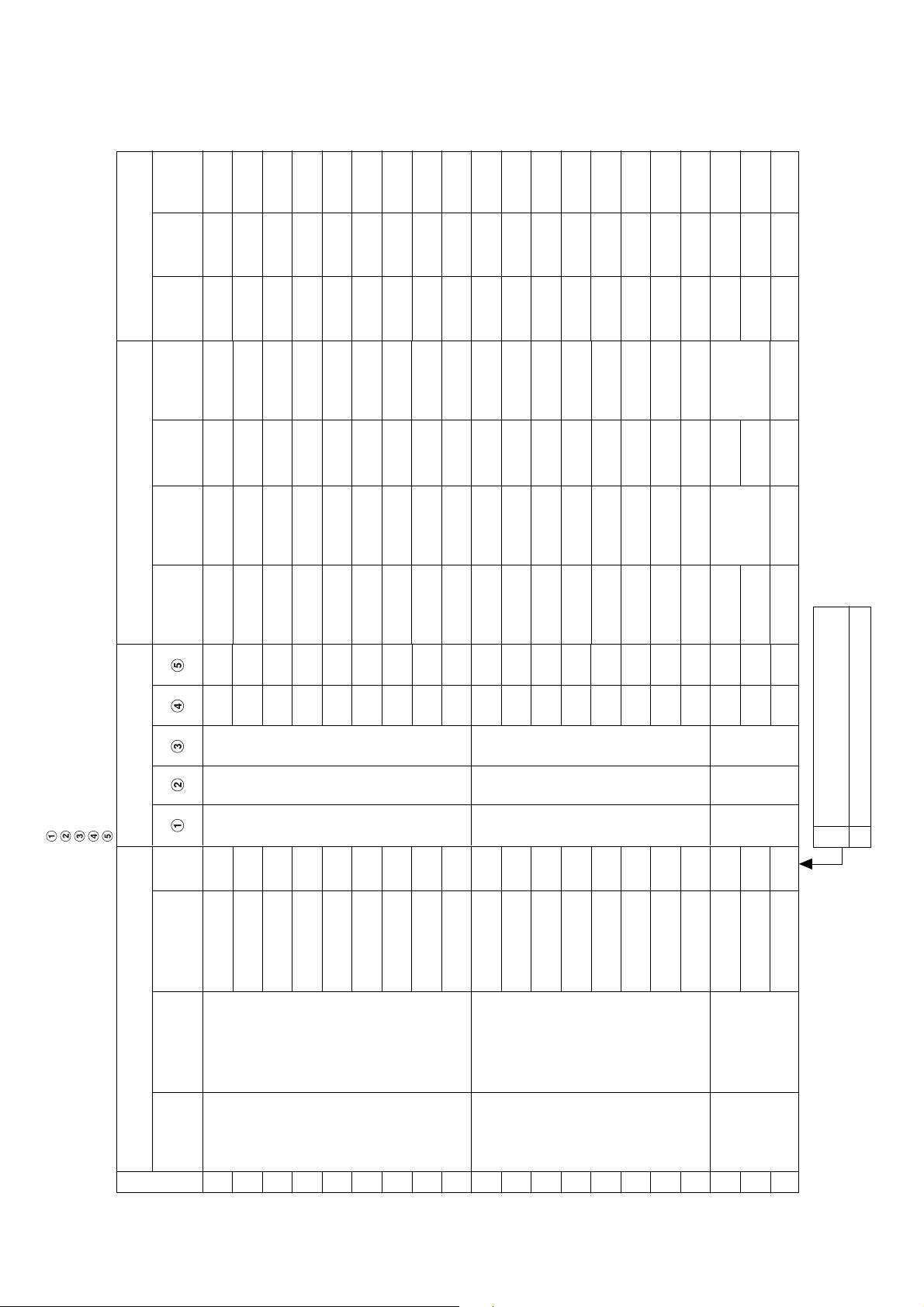
(Example)
No.
Fire alarm
No.
Key input
1
1
1
1
1
1
1
1
1
1
1
1
1
1
1
1
1
2
2
2
1
1
1
1
1
1
1
1
1
1
1
1
1
1
1
1
1
2
2
2
Power meter No. and
Input/Output data No.
Power
R.C. group/
Area
Tenant
Block
1
meter No.
unit
PAC-B • 1F-1
name
Shop A
name
Tenant A
1F
name
1
1
1
PAC-B • 1F-1
Shop A
Tenant A
1F
2
2
1
1
PAC-B • 1F-1
PAC-B • 1F-1
Shop A
Shop A
Tenant A
Tenant A
1F
1F
2
2
3
4
1
1
PAC-B • 1F-1
PAC-B • 1F-2
Shop A
Shop B
Tenant A
Tenant B
1F
1F
2
0
5
6
1
1
1
PAC-B • 1F-3
PAC-B • 1F-4
Shop C
Shop D
Tenant B
Tenant B
1F
1F
0
0
7
8
1
2
PAC-B • 1F-5
PAC-M • 1F-1
Shop E
Shop F
Tenant B
Tenant C
1F
1F
0
0
9
1
2
2
PAC-M • 1F-2
PAC-M • 1F-3
Shop F
Shop G
Tenant C
Tenant C
1F
1F
0
0
2
3
2
2
PAC-M • 1F-4
PAC-M • 1F-5
Office
Shop G
Office A
Tenant C
1F
1F
0
0
4
5
2
2
2
PAC-M • 1F-6
PAC-M • 1F-7
Office
Meeting room
Office A
Office A
1F
1F
0
0
6
7
2
3
PAC-S • 2F-1
PAC-M • 1F-8
A
Meeting room
Office A
Shared space
1F
2F
0
1
8
1
3
B
2F
2
2
3
3
PAC-S • 2F-2
Shop H
Tenant D
2F
0
3
Address Information Display name
Intelligent Server address
TCS-NET relay I/F address
Line address
Indoor unit address
Group address
unit
Header
Indoor unit
model name
Air Conditioner List
model name
Outdoor unit
Outdoor
refrigerant
• Building name: XXX Building
1
MMU-AP0091H
system
1
0
0
0
MMU-AP0091H
MMU-AP0091H
MMU-AP0091H
2
3
4
1
1
0
1
1
MMK-AP0091H
MMU-AP0091H
MMY-AP1401HT8
PAC-B
5
MMK-AP0091H
6
7
1
1
1
MMK-AP0091H
MMK-AP0091H
MMK-AP0091H
8
9
10
1
1
1
1
1
MMK-AP0091H
MMK-AP0091H
MMK-AP0091H
MMY-AP1401HT8
PAC-M
11
12
13
1
1
1
MMK-AP0091H
MMK-AP0091H
MMK-AP0091H
14
15
16
1
1
1
1
0
MMK-AP0091H
MMK-AP0091H
MMK-AP0091H
MMY-AP1401HT8
PAC-S
17
18
19
Header indoor unit of group control.
Indoor unit on individual control.
Follower indoor unit of group control.
1
0
1
MMK-AP0091H
20
28
Page 29
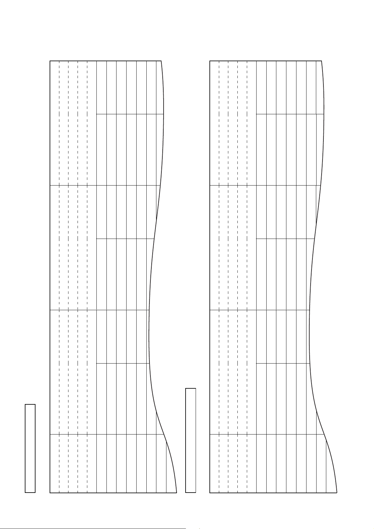
3-2-4 Schedule table
Run
Stop
:
:
:
:
:
:
:
:
PAC-B, 1F-6
Night-duty room
B1
8:00
9:30
Monday to Saturday
Run
Stop
Stop
10:00
Run
Run
16:30
Stop
Stop
22:00
Stop
Stop
23:58
:
:
:
:
:
:
:
:
:
:
PAC-B, 1F-3 to 1F-5
Warehouse
XX Electric Co., Ltd.
B1
:
:
:
:
:
:
:
:
PAC-B, 1F-1
Consultation room
XX Dental Clinic
B1
8:00
12:00
13:00
19:00
Monday to Friday
Run
Stop
Stop
8:00
19:00
Monday to Saturday
:
21:00
21:00
:
:
:
:
:
:
:
Schedule Table ( / )
R.C. group/unit
Area
• Building name:
Tenant
1
Block
Day of the week
2
3
4
5
6
7
8
Schedule Table (Example)
R.C. group/unit
Area
Tenant
• Building name: XXX Building
Block
1
2
3
Day of the week
4
5
6
7
8
29
Page 30
3-3 Setup file creation
Create setup files according to the control wiring system diagram and the address table.
3-3-1 Setup file creation software (Excel macro)
• The setup file creation software is used to create setup files to be installed on the Touch Screen
Controller.
• In the air conditioning control system, setting values are defined in accordance with the air conditioner
installation conditions within the building. If a wrong value is set, a problem such as an interruption in
communication with the air conditioner will occur.
• Setting items: Air conditioner information, device information, Touch Screen Controller display
information.
• A operator enters details on the Excel spreadsheet and then creates 23 setup files using the information
entered.
Operating environment and others
Operating environment Windows 2000 or newer
OS
Excel
Excel 2000 or newer is required separately.
System Configuration
Setup file creation software for Touch Screen Controller
Excel
Provided from installation
company and building
Default data file
Product information file
Setup file
• Tenant name, etc.
• Air conditioner information, etc.
• Setting values for energy monitoring
and billing
Air conditioner specific characteristic values
Tenant names for reports
management company.
Setup file
Record on CF card
Air conditioner information
Location, indoor unit group setting,
control address (I/F, indoor, outdoor),
device type, product model, number
of devices
Device information
Power meter No., pulse constant,
fire alarm/door-lock input No.,
emergency output No.
Control display information
Block/area/tenant/R.C. Group, unit
names
Building operation information
Meter read date
Schedule (operation, charging)
Energy
monitoring I/F
Power meter
RS-485
Intelligent Server
TCS-NET
Relay I/F
Main BUS
Air conditioner
Touch Screen
Controller
Ethernet Ethernet
HUB
30
Set by scheduler function of
Touch Screen Controller.
Power
distribution
software
Printer
Page 31

3-3-2 Setup file contents
(1) Display setup file
• File name: DISP_FORM.DEF
•
Enter the entire building display mode, number of block display buttons, number of tenant display buttons,
number of area display buttons, number of R.C. group/indoor display buttons, and the schedule setting unit.
• For the entire building display mode, specify display unit when the entire building button is pressed.
[0: block, 1: tenant, 2: area, 3:
• For the number of buttons, enter the number of lateral buttons in each display mode. The number of
vertically arranged buttons is always 6.
• Specify schedule setting unit. [0: area, 1:
• Specify filter sign display mode. [0: no display, 1: display]
(2) Error code definition file
• File name: ERROR_CODE.DEF
• Enter reception code (hexadecimal), error code, error code name, display mode, and external
output.
• Specify display mode [0: no display (normal), 1: display].
• Specify external output [0: no output emergency, 1-64: emergency output No. (output to
corresponding number)].
(3) Touch Screen Controller IP address definition file
• File name: CONT_IP.DEF
• Enter the Touch Screen Controller IP address.
R.C. group/indoor
R.C. group/indoor
]
]
(4) Intelligent Server IP address definition file
• File name: LSV_IP.DEF
• Enter an Intelligent Server number and IP address.
(5) I/O Controller IP address definition file
• File name: IO_IP.DEF
• Enter the I/O Controller IP address.
• Only one address can be entered. Do not enter a IP address when the I/O Controller is not used.
(6) Building name definition file
• File name: BUILD_NAME.DEF
• Enter a building name.
(7) Block name definition file
• File name: BLOCK_NAME.DEF
• Enter a block number/name.
• Specify font size. [0 (small) -3 (large) 2 (standard)]
(8) Tenant name definition file
• File name: TENANT_NAME.DEF
• Enter tenant numbers/names (up to 512).
• Specify font size. [0 (small) -3 (large) 2 (standard)]
(9) Area name definition file
• File name: AREA_NAME.DEF
• Enter area numbers/names (up to 512).
• Specify font size. [0 (small) -3 (large) 2 (standard)].
(10) R.C. group/indoor name definition file
• File name: AC_NAME.DEF
• Enter
• Specify font size. [0 (small) -3 (large) 2 (standard)]
R.C. group/indoor
numbers/names (up to 512).
31
Page 32

(11) Door-lock input definition file
• File name: KEY_CH.DEF
• Enter door-lock input numbers (1-64), input device IDs, input channels, and signal logic (up to 64).
• When no door-lock input is used, do not enter.
• An input device ID means the following:
0 to 7: I/O module device ID
10: general-purpose input to the touch panel
100 or more: digital I/O interface (Second digit: Intelligent Server No., first digit: Relay Interface No.)
• Specify signal logic. [0: negative logic, 1: positive logic]
(12) Fire alarm input definition file
• File name: FIRE_CH.DEF
• Enter fire alarm input numbers (1-64), input device IDs, input channels, and signal logic (up to 64).
• When no fire alarm input is used, do not enter.
• An input device ID means the following:
0 to 7: I/O module device ID
10: general-purpose input to the touch panel
100 or more: digital I/O interface (Second digit: Intelligent Server No., first digit: Relay Interface No.)
• Specify signal logic. [0: negative logic, 1: positive logic]
(13) Emergency external output definition file
• File name: EMGOUT_CH.DEF
• Enter external emergency output numbers (1-64), output device IDs, and output channels (up to 64).
• When no external emergency output is used, do not enter.
• An output device ID means the following:
0 to 7: I/O module device ID
20: general-purpose output to the touch panel
100 or more: digital I/O interface (Second digit: Intelligent Server No., first digit: Relay Interface No.)
(14) R.C. group/indoor setup file
• File name: AC_MAP.DEF
• R.C. group/indoor No., Intelligent Server No., Relay Interface No., outdoor system No., indoor unit
address, device type, block No., tenant No., area No., key No., fire alarm No.
• Device type
0: SMMS, SHRM, 1: SDI, DI, 2: HA interface
•Key No.
0: no door-lock interlocking, 1-64: When a signal is input from the number defined in (11), a stop
command is sent to the system.
• Fire alarm No.
0: no fire alarm interlocking, 1-64: When a signal is input from the number defined in (12), a stop
command is sent to the system.
• Indoor unit set in this file is for the header unit only.
(15) Indoor unit group config file
• File name: AC_GROUP.DEF
•
R.C. group/indoor
address, device type, outdoor unit No., header/follower, tenant No.
• Used for energy monitoring and billing. No data is provided when energy monitoring and billing is not
performed.
(16) Outdoor unit group config file
• File name: OUT_GROUP.DEF
• Outdoor unit No., Intelligent Server No., Relay Interface No., system No., outdoor unit address,
device type
• Used for energy monitoring and billing. No data is provided when energy monitoring and billing is not
performed.
No., Intelligent Server No., Relay Interface No., outdoor system No., indoor unit
32
Page 33

(17) Power meter input definition file
• File name: WHM_CH.DEF
• Power meter No. (1-64), interface address, channel No., pulse generator constants
• Used for energy monitoring and billing. No data is provided when energy monitoring and billing is not
performed.
• An interface address means the following:
1 to 31: energy monitoring interface
100 or more: pulse counter interface (Second digit: Intelligent Server No., first digit: Relay Interface
No.)
• Pulse generator constants (kWh/pulse): Used by the energy monitoring and billing Excel macro
software, but not used by the controller.
(18) Report setup file
• File name: REPORT.DEF
• Daily report limit time (meter-read time), Monthly report limit date
(19) Operation mode setup file
• File name: RUN_MODE.DEF
• Operation mode range, scheduled operation central setting, door-lock interlocking central setting
• Operation mode range 0: all enabled, 16: cooling/dry/fan only, 32: heating/fan only
• Scheduled operation central setting
Setting
0
1
2
3
Stop (10 minutes later)
Stop
Stop + “run/stop” changeover
prohibition reset
Stop + “run/stop” changeover
prohibition reset
Stop + “run/stop” changeover
prohibition reset
Stop (within 10 minutes)
Stop
Stop + “run/stop” changeover
prohibition reset
Stop + “run/stop” changeover
prohibited
Stop + “run/stop” changeover
prohibited
Run
Run
Run + “run/stop” changeover
prohibition reset
“Run/stop” changeover
prohibition reset
Run + “run/stop” changeover
prohibition reset
• Door-lock interlocking central setting
Setting
0
1
2
3
* All these files must be included in the “¥DEF” folder.
Stop
Stop
Stop + “run/stop” changeover prohibited
Stop
Lock (OFF to ON)
Unlock (ON to OFF)
No operation
“Run/stop” changeover prohibition reset
“Run/stop” changeover prohibition reset
No operation
33
Page 34

3-4 Control system installation
3-4-1 External view
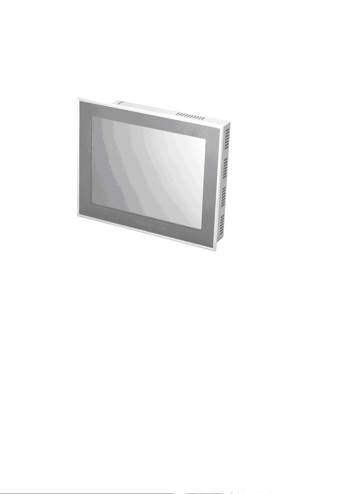
Touch Screen Controller
Model: BMS-TP0640ACE
BMS-TP5120ACE
BMS-TP0604PWE
BMS-TP5120PWE
CF (Compact Flash)
card slot (CF card for
data files)
Universal Input/
Output port
USB mouse
Ethernet port
Intelligent
Server
Power cable
54
549
242
99.3
M4 Tap (×4 pcs.)
(depth: 10 mm max.)
16
Power input
terminal block
82.5
48
75
302
PCI expansion unit
connector cover
70 75
55.5
19 30
POWER LED
Function switch (F1, F2, F3)
316
249
95.7591.75
256
unit: mm
34
Page 35

Intelligent Server
Model: BMS-LSV2E
Metal case type
Do not remove.
CAUTION
CF (Compact Flash)
card slot
Touch Screen Controller
(Ethernet)
WARNING
Do not decompose.
370
Not used
Relay Interface
(RS-485)
19839
42
Power switch
35
unit: mm
Page 36

TCS-NET Relay Interface
Model: BMS-IFLSV1E
Parts name
1
Case
2
Case lid
3
Grommet
4
Grommet
5
Grommet for power supply
Specifications
Galvanized sheet metal
Galvanized sheet metal
C30-SG20A
C30-SG20A
C30-SG20A
200
1
2
6- 5.5 mounting holes
22787822
66
63.6
3
4
170
146.9
5
22787822
156
unit: mm
36
Page 37

Energy monitoring R I/F • Digital I/O R I/F
Model: BMS-IFWH3E
BMS-IFDD01E
234
Grommet for
power input
1818 53.5 103.5
220
1818
Grommet for
power meter
92.5
(193)
Grommet for
RS-485
64.5
Grommet for DO
246
63.6
unit: mm
37
Page 38

3-4-2 Installation method
Touch Screen Controller
Make a space for the installation and service.
Install the Touch Screen Controller in a wall (standard) or on a dedicated stand (when available on site).
In-wall installation
■■
■Conditions for installation
■■
A space of 30 mm or more between the controller
and surrounding objects is required.
Panel
30 mm or more (top)
30 mm or more (bottom)
30 mm or more (rear)
Top view
30 mm or more (side)
Interface side
Panel
■■
■Attaching Fixture
■■
■Panel cut size
+1
303
-0
R1 or less
REQUIREMENT
+1
-0
Use a panel
243
(procured on site)
with a thickness of
1.6-1.7 mm.
Panel thickness: 1.6 -1.7 mm
[mm]
1. Insert the controller from the outside of the panel.
2. Insert the fixtures from the inside of the panel.
Touch Screen
Controller
Panel
Fixture
Bottom view
For reference
Display stand (not supplied with the controller)
Use a CONTEC stand (model: IPC-SND-03).
For details of the stand, visit the CONTEC web site.
Europe: http://www.contec-europe.com
China: http://www.contec.sh.cn
REQUIREMENT
• Check that the installation dimensions on the rear of the
Touch Screen Controller match the installation
dimensions on the CONTEC stand.
• Use the screws supplied with the stand to install the
controller.
38
Tightening screws excessively
may cause the screws to break.
Optimum tightening torque is
0.6N/m.
75 mm
75 mm
Angle adjustment lock screw.
(Loosen the screw and adjust angle.)
Page 39

Intelligent Server Installation Method and Orientation
There are four ways to install the Intelligent Server as shown below: (1) rack mount (2) surface mount (3)
wall mount A, and (4) wall mount B. The rack mount installation requires a support bracket for a 19-inch
rack. Please contact distributor if you need the support bracket.
Use the four bottom screw holes for the wall mount installation.
(1)Rack mount
A support bracket is required to be
fixed to the bottom (rear side) of the
unit.
(3)Wall mount -A
Wall mount with the front side upwards
(2)Surface mount
Standard installation
(4)Wall mount -B
Wall mount with the left side upwards
(Unit: mm)
AC inlet side
308.4 30.830.8
LED side
Screw hole for wall
mount (M4 × 4 pcs.)
30 133 35
REQUIREMENT
Do not install the unit in any of the following places.
• Humid or wet place
• Dusty place
• Place exposed to direct sunlight
• Place where there is a TV set or radio within one meter
• Place exposed to rain (outdoors, under eaves, etc.)
39
Page 40

TCS-NET Relay Interface
■■
■Installation Method and Orientation
■■
There are five installation methods for this relay interface as shown below: surface mount and wall mount.
Use the supplied screws.
No good
REQUIREMENT
Do not install the unit in any of the following places.
• Humid or wet place
• Dusty place
• Place exposed to direct sunlight
• Place where there is a TV set or radio within one meter
• Place exposed to rain (outdoors, under eaves, etc.)
■■
■Installation Space and Maintenance Space
■■
Ensure a minimum space of 100mm is left at the side and top of the device
for connecting cables to enter the cable inlets and maintenance of the
device. As shown in the figure.
The other sides can be directly adjacent to surrounding objects.
100mm
100mm
Energy monitoring Relay I/F • Digital I/O Relay I/F
■■
■Installation Method and Orientation
■■
There are five installation methods for this relay interface as shown below: surface mount and wall mounts.
Use the supplied screws.
No good
REQUIREMENT
Do not install the unit in any of the following places.
• Humid or wet place
• Dusty place
• Place exposed to direct sunlight
• Place where there is a TV set or radio within one meter
• Place exposed to rain (outdoors, under eaves, etc.)
■■
■Installation Space and Maintenance Space
■■
Ensure a minimum space of 100mm is left at the two sides and top of
the device for connecting cables to enter the cable inlets and
maintenance of the device. As shown in the figure.
The other sides can be adjacent to surrounding objects.
40
100mm
100mm
100mm
Page 41

3-4-3 Device specifications
Touch Screen Controller
Device, model
Touch Screen
Controller
BMS-TP0640ACE
BMS-TP5120ACE
BMS-TP0640PWE
BMS-TP5120PWE
Intelligent Server
Device, model
Intelligent Server
BMS-LSV2E
Relay Interface
Device, model
TCS-NET
Relay Interface
BMS-IFLSV1E
Item
Power supply
Power consumption
External dimensions
Weight
Ambient temperature
Ambient humidity
Item
Power supply
Power consumption
External dimensions
Weight
Ambient temperature
Ambient humidity
Item
Power supply
Power consumption
External dimensions
Weight
Ambient temperature
Ambient humidity
Chassis material
Specification
100 - 240 V, AC 50/60 Hz
50 VA
316 (W) x 256 (H) x 54 (D) mm
3.5 kg
0 to 40 °C
20 to 85%RH
Specification
85 - 132 V, 180 - 264 V, AC 50/60 Hz
30 VA
370 (W) x 42 (H) x 198 (D) mm
2.5 kg
0 to 40 °C
10 to 90%RH
Specification
220 - 240 V, AC 50/60 Hz
2.4 W
170 (W) x 66 (H) x 200 (D) mm
1 kg
0 to 40 °C
10 to 90%RH (no condensation)
Galvanized sheet metal 0.8t (no coating)
Energy Monitoring Interface
Device, model
Power supply
Power consumption
Energy monitoring
Relay Interface
BMS-IFWH3E
External dimensions
Weight
Ambient temperature
Ambient humidity
Chassis material
Digital I/O Interface
Device, model
Power supply
Power consumption
Digital I/O Relay
Interface
BMS-IFDD01E
External dimensions
Weight
Ambient temperature
Ambient humidity
Chassis material
Item
Item
Specification
220 - 240 V, AC 50/60 Hz
2.8 W (Energy monitoring)
193 (W) x 66 (H) x 246 (D) mm
1.65 kg
0 to 40 °C
10 to 90%RH
Galvanized sheet metal 0.8t
Specification
220 - 240 V, AC 50/60 Hz
6.5 W
193 (W) x 66 (H) x 246 (D) mm
1.65 kg
0 to 40 °C
10 to 90%RH
Galvanized sheet metal 0.8t (no coating)
41
Page 42

3-5 Wiring
3-5-1 Wiring specifications
Power supply specifications
Device Input voltage
Touch Screen Controller
Intelligent Server
TCS-NET Relay Interface
Energy Monitoring Relay Interface
Digital I/O Relay Interface
100 - 240 V, AC 50/60 Hz
85 - 132 V, AC 50/60 Hz
180 - 264 V, AC 50/60 Hz
220 - 240 V, AC 50/60 Hz
Power
consumption
50 VA
30 VA
2.4 W
2.8 W
6.5 W
Power cable
wire size
0.75 mm
2
Remarks
Procure on site
Communication wiring specifications
Inter-device connection
Intelligent Server ↔ TCS-NET
Relay Interface
Intelligent Server ↔ Energy
Monitoring Relay Interface
Intelligent Server ↔ Digital I/O
Relay Interface
TCS-NET Relay Interface ↔ Air
conditioner
Energy Monitoring Relay Interface
↔ Power Meter
Digital I/O Relay Interface ↔ Digital
Input/Output
*1: Use the D-sub (9 pin) wire supplied with the Intelligent Server software. If the length is to short, use a shielded wire.
*2: Total length per TCS-NET Relay Interface
Control wiring
specifications
D-sub (9-pin) wire *
(If length is short) Use a
shield wire
Shield wire
Shield wire
Shield wire
Shield wire
1
Number of
cores
4
2
2
2
2
2
2
2
Diameter
2
(mm
)
2
1.25 mm
2
1.25 mm
2
1.25 mm
2
1.25 mm
2
2.0 mm
2
0.3 mm
2
0.3 mm
Length
(m)
Max. 500
Max. 500
Max. 500
Max.1000*
Max.2000*
Max. 100
Max. 100
Polarity
With polarity
With polarity
With polarity
2
No polarity
2
No polarity
No polarity
With polarity
Remarks
Supplied with
Intelligent
Server software
Procure on site
Procure on site
Procure on site
Procure on site
Procure on site
Procure on site
Procure on site
Ethernet wire specifications
When Switching HUB is not used
Inter-device connection
Touch Screen Controller ↔
Intelligent Server
Control wiring
specifications
Ethernet (cross)
Category 5 UTP cross wire
When Switching HUB is used
Inter-device connection
Touch Screen Controller ↔
Switching HUB
Switching HUB ↔ Intelligent
Server
Control wiring
specifications
Ethernet (straight)
Category 5 UTP straight wire
Ethernet (straight)
Category 5 UTP straight wire
Number of
cores
Number of
cores
42
8
8
8
Diameter
2
(mm
)
–
Diameter
2
(mm
)
–
–
Length
(m)
Max. 100
Length
(m)
Max. 100
Max. 100
Polarity
–
Polarity
–
–
Remarks
Procure on site
Remarks
Procure on site
Procure on site
Page 43

3-5-2 Wiring diagram
Yellow
Brown
B
A
Red
Orange
Crimp 3 wires with a closed
end wire connector.
A
B
Red/Orange
Brown/Yellow
Power supply
Power supplyPower supplyPower supplyPower supplyPower supply
FG
U1U2
TCC-LINK
ABLNLNLNLNLN LN
FG
U1U2
TCC-LINK
AB
SW6
ON
TCC-LINK
TERMINATOR
12
SW5
RS-485
ON
TERMINATOR
1
2
RS-485
TCS-NET RELAY
INTERFACE
SW6
ON
TCC-LINK
TERMINATOR
12
SW5
ON
RS-485
TERMINATOR
1
2
RS-485
TCS-NET RELAY
INTERFACE
ADDRESS
ADDRESS
U4U3
U2U1
Outdoor
unit
SW1
8
U2U1
U2U1
Indoor unit
Remote
controller
U4U3
U2U1
Outdoor
unit
SW1
1
U2U1
Remote
controller
U2U1
Indoor unit
Outdoor
unit
Indoor unit
Remote
controller
Outdoor
unit
Indoor unit
Remote
controller
U4U3
U2U1
U2U1
U4U3
U2U1
U2U1
U4U3
Indoor unit
U4U3
Indoor unit
Central remote
controller
Central remote
controller
INTELLIGENT SERVER
(BMS-LSV2E)
TOUCH SCREEN CONTROLLER
(BMS-TP0640/5120)
SW1
4
ADDRESS
DIGITAL I/O
INTERFACE
(BMS-IFDD01E)
SW1
1
ADDRESS
DIGITAL I/O
INTERFACE
(BMS-IFDD01E)
SW1
4
ADDRESS
DI 1
DI 2
DI 3
DI 4
DI 5
DI 6
DI 7
DI 8
DI 1
DI 2
DI 3
DI 4
DI 5
DI 6
DI 7
DI 8
DI 1
DI 2
DI 3
DI 4
DI 5
DI 6
DI 7
DI 8
Input contact 1
Input contact 2
Input contact 3
Input contact 4
Input contact 5
Input contact 6
Input contact 7
Input contact 8
B
RS-485
A
DO1
DO2
DO3
DO4
GND
+12V
B
RS-485
A
DO1
DO2
DO3
DO4
GND
+12V
Load 1
Load 2
Load 3
Load 4
Input contact 1
Input contact 2
Input contact 3
Input contact 4
Input contact 5
Input contact 6
Input contact 7
Input contact 8
Load 1
Load 2
Load 3
Load 4
Power meter 1
Power meter 2
Power meter 3
Power meter 4
Power meter 5
Power meter 6
Power meter 7
Power meter 8
TOUCH SCREEN CONTROLLER CONNECTION DIAGRAM
ENERGY
MONITORING
INTERFACE
SW1
1
ADDRESS
ENERGY
MONITORING
INTERFACE
43
DI 1
DI 2
DI 3
DI 4
DI 5
DI 6
DI 7
DI 8
B
RS-485
A
Power meter 1
Power meter 2
Power meter 3
Power meter 4
Power meter 5
Power meter 6
Power meter 7
Power meter 8
B
RS-485
A
Page 44

CAUTION
ON
1 2
ON
1 2
polarity. Connect A to A, and B to
B. If connected with incorrect
polarity, the unit will not work.
• The RS-485 signal lines have
SW1
4
LED4
LED3
SW2 SW3
LED2
SW7 LED1
SW4
N
O
2
1
3
LED5
• The Main BUS signal lines have
35 10
no polarity.
REQUIREMENT
Install a breaker at the primary side
of the power supply.
Connect the shielded wire of the
RS-485 communication wire to the
earth on the Intelligent server side.
Do not connect the shielded wire
to the terminal block. It should be
Connect the shielded wire of the
Main BUS communication wire to
the earth on the air conditioner
side. Do not connect the shielded
wire to the terminal block. It should
Connections (TCS-NET RELAY INTERFACE (BMS-IFLSV1E)
Connect power cables earth wires and signal cables to the specified terminals on the terminal block.
open and insulated.
SW6
ON
FG
be open and insulated.
Air conditioner
Secure each cable
with a cable clamp.
12
SW5
ON
TCC- LINK
U2 U1
Intelligent server
12
RS-485
BA
LN
Power supply
Connect the earth
wire to the earth
terminal on the
chassis.
Length of stripped RS-485
communication wire
L
N
35 10
Length of stripped power
cable
55 10
44
Page 45

U4U3
U4 U3
Outdoor
unit
Central
remote controller
U2 U1
U2 U1
Indoor
unit
U2 U1
Remote
controller
U4U3
U4 U3
Outdoor
unit
Central
remote controller
U2 U1
U2 U1
Indoor
unit
U2 U1
Remote
controller
Main BUS terminator resistor is set on the air conditioner
side. Bit 1 and 2 of SW6 should be OFF.
Set the RS-485 terminator resistor on the No.1 (relay
interface address SW1=1) unit and the Intelligent Server
only. Do not set it here.
SW6
ON
The shield of Main BUS
cable should be open
and insulated. It is not
connected to the
terminal block.
Main BUS U1 and U2
have no polarity.
FG
2
1
U1U2
U4U3
Outdoor
unit
2
1
SW5
ON
RS-485
AB
TCC-LINK
A
B
Brown/Yellow
Red/Orange
U2 U1
Indoor
SW1
8
ADDRESS
U2 U1
unit
Indoor unit
Remote
controller
Power
supply
SW6
Indoor unit
U2 U1
U4U3
Outdoor
unit
2
2
1
1
SW5
ON
ON
RS-485
AB
FG
U1U2
TCC-LINK
Indoor
SW1
1
ADDRESS
U2 U1
unit
LNLN
Power
Remote
controller
supply
Set the TCS-NET Relay Interface address with SW1. Assign 1 to 8 to each
address to avoid duplication.
CAUTION: The SW1 setting is read when the power is turned on. Push the
reset switch SW7 after changing the address.
INTELLIGENT SERVER
(BMS-LSV2E)
TOUCH SCREEN CONTROLLER
(BMS-TP0640/5120)
Connection diagram (TCS-NET RELAY INTERFACE (BMS-IFLSV1E))
Crimp 3 wires with
a closed end wire
connector.
Yellow
Brown
B
A
Orange
Red
Connect the two shield wires
together.
45
The shield of RS-485 cable should be open and
insulated. It is not connected to the terminal block.
CAUTION: RS-485 signals A and B have polarity. Be
careful when connecting the RS-485 wires.
Set the RS-485 terminator resistor on the No.1 (relay interface address SW1=1)
unit. Set bit 1 of SW5 to ON.
Page 46

Insert the wire by pushing the
lever with a screwdriver. Check
that the wire is inserted
securely.
When inserting two RS-485
communication wires into a single
terminal for connection to another
interface, crimp them using the
supplied pin terminal.
CAUTION
The RS-485 signal wire has
polarity. Connect A to A, and B to
B. If connected with incorrect
polarity, the unit will not work.
REQUIREMENT
Install a breaker on the primary
side of the power supply.
Secure each
cable with a
cable clamp.
DI1DI2DI3DI4DI5DI6DI7DI8
SW3
ON
SW2
1234
Power meter
Intelligent Server
BA
FG
RS-485
35 6
Length of stripped
power meter wire
6
35
Length of stripped
communication wire
SW1
Connections (ENERGY MONITORING RELAY INTERFACE (BMS-IFWH3E))
Connect power cables, earth wires, and signal wires to the specified terminals on the terminal block.
SW4 SW7
Connect the earth
wire to the earth
terminal on the
chassis.
Secure each cable
with a cable clamp.
L
46
N
10
35
Length of stripped
power cable
55 10
Power cable
Page 47

Wiring Connection
The following describes the wiring connections of the Energy Monitoring Relay Interface when it is used
in the air conditioner control system.
• Terminator resistor setting
Set the RS-485 terminator resistor on the TCS-NET Relay Interface.
Do not set it by the Energy Monitoring Relay Interface.
• Shield earthing
The shield earth of the RS-485 signal wires should be single-point earth. Earth the wires on the
Intelligent server side.
Other shield lines should be closed and the terminal end should be open and insulated.
• Connection of power meter
Use a power meter with a pulse generator.
Connect the non-voltage contact output of the power meter to the Energy Monitoring Relay Interface.
An external input circuit is shown below.
Input signal is electrically isolated by a photo-coupler.
12V
Power meter
Input
terminal
(with pulse generator)
Energy Monitoring Relay Interface
DI-1 to DI-8
Contact
47
Page 48

Yellow
Brown
B
A
Red
Orange
Crimp 3 wires with a
close end wire connector.
INTELLIGENT SERVER
(BMS-LSV2E)
TOUCH SCREEN CONTROLLER
(BMS-TP0640/5120)
A
B
Power supply
Red/Orange
Brown/Yellow
FG
U1U2
ABLN
SW1
4
ADDRESS
TCC-LINK
RS-485
TCS-NET RELAY
INTERFACE
DI 1
DI 2
DI 3
DI 4
DI 5
DI 6
DI 7
DI 8
CAUTION: No terminator resistor
setting switch is provided on the
Energy Monitoring Relay Interface.
Power meter 1
Power meter 2
Power meter 3
Power meter 4
Power meter 5
Power meter 6
Power meter 7
Power meter 8
Set the RS-485 terminator resistor
on the TCS-NET Relay Interface.
Connect the
respective
shield wires of
the two cables.
The shield earth of
the RS-485 signal
wires should be a
single-point earth.
Earth the wires on
the Intelligent server
side. Do not earth
here.
Power supplyPower supply
ENERGY
MONITORING
INTERFACE
SW1
1
ADDRESS
LNLN
ENERGY MONITORING
INTERFACE (BMS-IFWH3E)
DI 1
DI 2
DI 3
DI 4
DI 5
DI 6
DI 7
DI 8
B
A
RS-485
CAUTION: RS-485
signals A and B
have polarity. Be
careful when
connecting the RS-
485 wire.
Power meter 1
Power meter 2
Power meter 3
Power meter 4
Power meter 5
Power meter 6
Power meter 7
Power meter 8
B
A
RS-485
Set the Energy Monitoring Relay
Interface address with SW1. Assign 1 to
Connection diagram (ENERGY MONITORING RELAY INTERFACE (BMS-IFWH3E))
4 to each address to avoid duplication.
Each interface has its own address and
can be set independently.
CAUTION: The SW1 setting is read
when the power is turned on. Push the
reset switch after changing the address.
48
CAUTION: RS-485 signals A
and B have polarity. Be
careful when connecting the
RS-485 wire.
Page 49

Insert the wire by pushing the
lever with a screwdriver. Check
that the wire is inserted securely.
Secure each
cable with a
cable clamp.
DI1DI2DI3DI4DI5DI6DI7DI8
Digital input
contacts
When inserting two RS-485
communication cables into a
single terminal for connection to
another interface, crimp them
using the attached pin terminal.
Intelligent
Server
B
A
FG
RS-485
Digital output
DO1
DO2
DO3
load
DO4
GND
+12V
CAUTION
The RS-485 signal wire has
polarity. Connect A to A, and B to
B. If connected with incorrect
polarity, the unit will not work.
35 6
Length of stripped digital
Input/Output connector wire
REQUIREMENT
Install a breaker at the primary side
of the power supply.
SW3
ON
SW2
SW1
Connections (DIGITAL I/O RELAY INTERFACE (BMS-IFDD01E))
Connect power cables, earth wires, and signal wires to the specified terminals on the terminal block.
1234
SW4 SW7
Secure each
Connect the earth
wire to the earth
terminal on the
chassis.
cable with a cable
L
clamp.
6
35
Length of stripped
communication wire
N
10
35
Length of stripped
power cable
55 10
Power cable
49
Page 50

Wiring Connection
CAUTION
If an inductive load (relay coil) or a bulb is connected, a voltage surge or rush of current will be
generated. Take adequate measures against these scenarios.
The following describes wiring connections of the Digital I/O Relay Interface when it is used in the air
conditioner control system.
• Terminator resistor setting
Set the RS-485 terminator resistor on the TCS-NET Relay Interface.
Do not set it by the Digital I/O Relay Interface.
• Shield earthing
The shield earth of the RS-485 signal wires should be a single-point earth. Earth the wires on the
Intelligent Server.
Other shield lines should be closed and the terminal end should be open and insulated.
• Connection of external digital inputs
Input circuit examples are shown below (electrically isolated using a photo-coupler).
(1) Example of contact input connection
12V
Input terminal
DI-1 to DI-8
Contact
(2) Example of current sink connection
12V
Input terminal
DI-1 to DI-8
Current sink
• Connection of external digital outputs
Output circuit examples are shown below (open collector output electrically isolated using a photocoupler).
(1) Example of load connection
12V
Output terminal
DO1 to DO4
GND
Load
External
power
supply
(2) Example of load connection
12V
+12V
Output terminal
DO1 to DO4
50
Page 51

Yellow
Brown
B
A
Red
Orange
Crimp 3 wires with a
closed end wire connector.
INTELLIGENT SERVER
(BMS-LSV2E)
TOUCH SCREEN CONTROLLER
(BMS-TP0640/5120)
Connect the two
shield wire
together.
A
B
Power supply
Red/Orange
Brown/Yellow
FG
U1U2
AB
LNLNLN
SW1
4
ADDRESS
TCC-LINK
RS-485
TCS-NET RELAY
INTERFACE
DI 1
DI 2
DI 3
DI 4
DI 5
DI 6
DI 7
DI 8
The RS-485 signal wire has
Input contact 1
Input contact 2
Input contact 3
Input contact 4
Input contact 5
Input contact 6
Input contact 7
Input contact 8
polarity A and B. Be careful when
connecting the wire.
Set the Digital I/O Relay Interface
address with SW1. Assign 1 to 4 to
each address to avoid duplication.
You can set the digital Input/Output
Relay Interface address
independently from the Main BUS
Connection diagram (DIGITAL I/O RELAY INTERFACE (BMS-IFDD01E))
CAUTION: Set the
RS-485 terminator
resistor on the TCS-
NET Relay
Interface. No
terminator resistor
Power supplyPower supply
The shield earth of
the RS-485 signal
wires should be
single-point earth.
Earth the wires on
the Intelligent
Server.
Relay Interface address or the
Energy Monitoring Relay Interface
address.
CAUTION: The SW1 setting is read
when the power is turned on. Push
the reset switch (SW7) after
changing the address.
DIGITAL I/O
INTERFACE
setting switch is
provided on the
Digital I/O Relay
Interface.
(BMS-IFDD01E)
DIGITAL I/O
INTERFACE
(BMS-IFDD01E)
SW1
1
ADDRESS
DI 1
DI 2
DI 3
DI 4
DI 5
DI 6
DI 7
DI 8
DO1
DO2
DO3
DO4
GND
+12V
DO1
DO2
DO3
DO4
GND
+12V
B
A
B
A
RS-485
RS-485
Load 1
Load 2
Load 3
Load 4
Input contact 1
Input contact 2
Input contact 3
Input contact 4
Input contact 5
Input contact 6
Input contact 7
Input contact 8
Load 1
Load 2
Load 3
Load 4
51
Page 52

3-6 Network connection
Connecting the Network Wires
Connect the Touch Screen Controller to the Intelligent Servers and to an optional PC for creating monthly
reports using network wires (category 5UTP straight wire), via a Switching HUB (procured on site).
• Connect the Ethernet port of the controller to a port of the HUB with a network wire.
• Connect the Ethernet port 1 on the Intelligent Server to a port on the HUB with a network wire.
• Connect the PC’s Ethernet port to a port on the HUB with a network wire. (Not required if there is no
requirement to create reports.)
Ethernet
Touch Screen Controller
Network wires
(category 5UTP straight wire)
Ethernet port
Switching HUB
Ethernet port 1
Ethernet port 2
PC for creating monthly reports
Intelligent Server No.1
Intelligent Server No.2
52
Page 53

3-7 Control system configuration
To connect the touch screen controller, intelligent server, and PC for energy monitoring and billing via
switching HUB, setting of IP addresses on all devices is necessary.
Device IP address
Touch screen controller: 192.168.2.69 (default address)
192.168.2.70
•
•
Intelligent server: 192.168.2.100 (default address)
192.168.2.101
•
•
PC for energy monitoring and billing: 192.168.2.** (**: Set number except from 69 to 149)
53
Page 54

54
Page 55

4
ADDRESS SETTING
4-1 Address setting flow
4-2 Definition of address
4-3 Address setting for air conditioner
4-3-1 Setting for VRF system
(1) Check at main Power-ON
(2) Manual setting from wired remote controller
(3) Line (system) address setting
(4) Power reset
(5) Indoor unit address check
(6) Trial operation
(7) Setup of relay connector and terminator
(8) Central control address setting
(9) Trial operation for central controller (TCB-SC642TLE2)
(10) Automatic address setting (for reference)
(11) Clearance of address
(12) Confirmation of indoor unit address and position by using
the remote controller
(13) Address change from remote controller
(14) In case of increase the address-undefined indoor units
(Extension, etc.)
(15) Address setup example (VRF system)
4-3-2 Setting for 1 to 1 system
(1) Address re-setup
(2) Indoor address change example
4-4 Address setting for control system devices
4-4-1 Address setting flow
4-4-2 Setting for Intelligent Server
4-4-3 Setting for TCS-Net relay interface
4-4-4 Setting for Energy monitoring relay interface
4-4-5 Setting for Digital I/O relay interface
55
Page 56

4-1 Address setting flow
Setting flow
Power ON
Manual address setting
Line address setting
Power reset
Indoor unit address check
Trial operation (Refrigerant system)
Contents
Indoor units/Outdoor units
Setting from main wired remote controller
(Line/Group/Indoor address setting)
Dip Switch setting on outdoor interface
P.C. board
Power reset to activate line address
7 segment display on outdoor interface
P.C. board check line/indoor address on
remote controller
Test operation in each refrigerant
system one by one
Reference No.
4-3-1 (1)
4-3-1 (2)
4-3-1 (3)
4-3-1 (4)
4-3-1 (5)
4-3-1 (6)
Setup of relay connector and SW30-2
Central controller exist ?
Central control device setting
Trial operation (Central control device)
TCS-NET control system address setting
Local server
TCS-NET relay I/F
Energy monitoring relay I/F
Digital I/O relay I/F
Central control wiring and terminator
setting
Local central remote controller setting
(Central remote controller, ON/OFF
controller, etc)
Test for local central control device
Switch setting
CF (Compact Flash) card mounting
4-3-1 (7)
4-3-1 (8)
4-3-1 (9)
4-4
Trial operation for Touch panel controller Operation from touch screen controller
56
Chapter. 5
Page 57

4-2 Definition of address
Indoor unit address
• “Indoor unit address” is to enable the outdoor unit to recognize an individual indoor unit.
This indoor unit address is allocated to every indoor unit one by one, for each refrigerant system.
(At shipment=99, Address unset)
Header Follower
12 34
Outdoor unit
Indoor unit
Remote
controller
Indoor unit
address
Header
Follower
12 34
Group address
• “Group address” is the address that recognizes group control and determines the header indoor unit and
follower indoor unit.
Group address and header indoor unit is determined automatically when automatic address setting is
performed.
(The indoor unit that becomes the header unit is indefinite, when automatic address setting is performed.)
Indoor unit on individual control : Group address = 0 (At shipment=99, Address unset)
Header indoor unit in group control : Group address = 1
Follower indoor unit in group control : Group address = 2
Outdoor unit
Indoor unit
Remote
controller
Indoor unit
address
Group
address
Header
12 34
Follower
Header Follower
HeaderFollower FollowerHeader Follower
12 34
00 12 02 12
Individual
control
Group
control
Individual
control
Group
control
57
Page 58

Line address (System address)
• “Line address” is the address in which a line (refrigerant system) of indoor units are connected.
This line address is set by Dip switch setting on the interface P.C. board of the header outdoor unit.
Dip Switch
setting
Line address
( Outdoor)
Central control
device
Outdoor unit
Indoor unit
Remote
controller
Line 1
(Refrigerant system 1)
Header
Follower
Line 2
(Refrigerant system 2)
Header Follower
Line
address
11111
(At shipment=99, Address unset)
2222 2
58
Page 59

Central control address
• “Central control address” is to enable central control devices to recognize each indoor unit.
This address can be set from the central control devices automatically or manually.
In case of group control on a VRF system, one central control address is allocated to each indoor unit in
a group control.
Line address
( Outdoor)
Central control
device
Outdoor unit
Indoor unit
Remote
controller
Line 1
(Refrigerant system 1)
Header
Follower
Line 2
(Refrigerant system 2)
Header Follower
Central
control
address
12134
Individual
control
(At shipment=99, Address unset)
5627
Group
control
59
Page 60

Zone address (Zone No.)
• “Zone address” is to be set when a central remote controller is used for each zone.
Zone address is set by a switch setting on the central remote controller.
Central remote controller can divide all indoor units into a maximum of 4 zones.
The zone to which the indoor unit belongs is determined by the central control address.
Central remote
controller
("All" mode)
Outdoor unit
Zone
address
Indoor unit
Central control address
1 to 16
17 to 32
33 to 48
49 to 64
Header
Follower
12
Central
Zone 1 RC*
Zone 1
Zone No.
Zone 1
Zone 2
Zone 3
Zone 4
Header Follower
Header
Zone 2
Central
Zone 2 RC*
Remote
controller
Central
control
address
12 34
(At shipment=99, Address unset)
17 18 19
* RC: Remote controller
20 21
60
Page 61

TCS-NET control system address
CF card
Compact
CF card
Compact
Flash
(Setup file)
Ethernet
Touch Screen Controller
(BMS-TP0640 / 5120)
PC for Energy Monitoring
and billing
(Procured on site)
Flash
InteIligent Server
Intelligent server
Switching HUB
(Procured on site)
RS- 485
(BMS-LSV2E)
No. = 1
TCS- NET
relay interface
(BMS-IFLSV1E)
No.1
No.2
Outdoor units Indoor units
1-1 1-2 1-3
2-1 2-2 2-3
3-1 3-2 3-3
4-1 4-2 4-3
.....
.....
.....
.....
Line address
=1
Line address
=2
Line address
=3
Line address
=4
CF card
Compact
Flash
Intelligent server
No. = 2
No.3
.....
No.1
Energy Monitoring relay in ter fac e
(BMS-IFWH3E)
No.2
No.1
Digital I/O relay interface
(BMS-IFDD01E)
No.2
No.1
No.2
Power meter
Power meter
Input
Input
6-1 6-2 6-3
7-1 7-2 7-3
5-1 5-2 5-3
Power meter
Input
Input
Line address
.....
Power meter
Power meter
Output
Output
Line address
.....
Line address
.....
=5
=6
=7
TCS-NET control system address
TCS-NET relay interface No.
Energy monitoring relay interface No.
Digital I/O relay interface No.
Interigent server No.
Number
1 to 8
1 to 4
1 to 4
1 to 4
Line address
8-1 8-2 8-3
No.1
Energy monitoring relay in ter fac e
(BMS-IFWH3E)
Power meter
Power meter
.....
Power meter
Setting method
Set by SW1 on P.C. board.
Set by SW1 on P.C. board.
Set by SW1 on P.C. board.
Set based on the setup data on the CF card of the touch
panel controller.
61
=8
Page 62

4-3 Address setting for air conditioner
4-3-1 Setting for VRF system
In this air conditioner, it is required to set up addresses on the indoor units before starting operation. Set
up the addresses according to the following setup procedure.
CAUTION
1. Set up address after wiring work.
2. Be sure to turn on the power in order of indoor unit → outdoor unit. If turning on the power in a
reverse order, a check code [E19] (Error of No. of header units) is output.
When a check code is output, turn the power on again.
3. To set up an address, it is unnecessary to operate the air conditioner.
4. Manual address setting is recommended for TCS-NET control system.
Manual address: Setup from the wired remote controller.
* It is temporarily necessary to set the indoor unit and wire 1 by 1.
(In group operation and when remote controller is not connected.)
5. Automatic address setup is also possible.
Automatic address: Setup from SW15 on the interface P.C. board of the header unit
It requires a maximum of 10 minutes (Usually, approx. 5 minutes) to set up automatically an
address to 1 refrigerant line.
6. To set up an address automatically, setup at the outdoor unit is necessary.
(Address setup cannot be performed by power-ON only.)
62
Page 63

4-3-1 (1) Check at main power-ON
After turning on the main power of the indoor units and outdoor units in the refrigerant system. Prior to
starting test operation, check the following items in each outdoor and indoor unit.
(After turning on the main power, be sure to check in order of indoor unit → outdoor unit.)
Check on outdoor unit
1. Check that all the rotary switches, SW01, SW02 and SW03 on the interface P.C. board of the header
outdoor unit are set to “1”.
2. If an error code is displayed on 7-segment [B], remove the cause of the fault .
3. Check that [L08] is displayed on the 7-segment display [B] on the interface P.C. board of the
header outdoor unit. (L08: Indoor address unset up)
(If the address setup operation has already been finished during service time, etc, the above check
code is not displayed and only [U1] is displayed on the 7-segment display [A].)
7-segment display [A]
Interface P.C. board
SW01 SW02 SW03
7-segment display [B]
Check on indoor unit
1. Display check on remote controller (In case of wired remote controller)
Check that a frame as shown in the following below figure is displayed on the LCD section of the remote
controller.
Normal status
(Power and operation stop)
(Power is not normally turned on.)
Abnormal status
If a frame is not displayed as shown in the above right figure, there is normally no power to the remote
controller. Therefore check the following items.
• Check power supply of
• Check wiring between indoor unit and
the
indoor unit.
the
remote controller.
• Check control wiring connection to the indoor control P.C. board and check for connection failure of
connectors.
• Check failure of transformer on the indoor P.C. board.
• Check indoor control P.C. board failure.
63
Page 64

4-3-1 (2) Manual setting from the wired remote controller
CAUTION
Be sure to allocate Line (system) /Group/Indoor address one by one to match the address setting
table and setup file that has been prepared beforehand.
If a incorrect value is set, a problem such as error communication with the air conditioner will occur.
Header
Outdoor unit
Indoor unit
Remote
controller
Indoor address
Group address
Line address
At shipment, all addresses are 0099 (Address unset status)
12 34
00 12
11 11
Follower
Line address
(At shipment:1)
Dip Switch setting
on interface P.C. board
Indoor, group, line
address are set
manually for each
refrigerant system
one by one.
(Step 1)
Arrange one indoor unit and one remote controller (RBC-AMT21E, RBC-AMT31E) set as 1 to 1.
Note:Do not use a simple remote controller or wireless remote controller.
(Address setting is not available.)
Connect wired remote
controller individually
when manual address
setting
64
Page 65

(Step 2)
Note)
When setting the line address from the remote controller, do not use address 29 or 30.
The address 29 and 30 cannot be set up in the outdoor unit. Therefore if they are incorrectly set up a
check code [E04] (Indoor/outdoor communication circuit error) is output.
Turn on the power.
1
Item code
Line (system) address
Indoor address
Group address
12
13
14
(Wiring example in 2 systems)
System System
#1
system
Indoor Indoor Indoor
Line address → 1
Indoor address → 1
Group address → 1
In the above example, under condition that
indoor units do not have individual remote
controllers, set the address after connecting a wired remote controller.
Remote
controller
Header
indoor
unit
1
2
2
1
3
2
Follower
indoor
unit
#2
system
Indoor Indoor
2
1
2
⎧⎧
⎧
⎧⎧
⎪⎪
⎪
⎪⎪
⎪⎪
⎪
⎪⎪
⎪⎪
⎪
⎪⎪
⎪⎪
⎪
⎪⎪
⎪⎪
⎪
⎪⎪
⎪⎪
⎪
⎪⎪
⎨⎨
⎨
⎨⎨
⎪⎪
⎪
⎪⎪
⎪⎪
⎪
⎪⎪
⎪⎪
⎪
⎪⎪
⎪⎪
⎪
⎪⎪
⎪⎪
⎪
⎪⎪
⎪⎪
⎪
2
2
2
⎪⎪
⎩⎩
⎩
⎩⎩
⎧⎧
⎧
⎧⎧
⎪⎪
⎪
⎪⎪
⎪
⎪
⎪
⎪⎪
⎪⎪
⎪
⎪⎪
⎪⎪
⎪
⎪⎪
⎨⎨
⎨
⎨⎨
⎪⎪
⎪
⎪⎪
⎪⎪
⎪
⎪⎪
⎪⎪
⎪
⎪⎪
⎪⎪
⎪
⎪⎪
⎩⎩
⎩
⎩⎩
Push simultaneously the + +
buttons for 4 seconds or more.
LCD changes to flashing.
(Line address)
2
Using the buttons, set on the item
code.
3
Using the buttons, set up the line
address.
(Match it with the line address on the interface P.C.
board of the header unit in the identical refrigerant
system.)
4
Push the button.
(OK when display goes on.)
(Indoor address)
5
Using the buttons, set on the item
code.
6
Using the buttons, set up the indoor
address.
7
Push the button.
(OK when display goes on.)
Group address
Individual : 0000
Header unit : 0001
Follower unit : 0002
⎩⎩
⎩
⎩⎩
⎨⎨
⎨
⎨⎨
In case of group control
⎧⎧
⎧
⎧⎧
Operation procedure
1 2 3 4 5 6
7 8 9 10 11
Data Item code
End
2, 5, 8
11
1
4, 7, 10
(Group address)
⎧⎧
⎧
⎧⎧
8
⎪⎪
⎪
⎪⎪
⎪⎪
⎪
⎪⎪
⎪⎪
⎪
⎪⎪
⎪⎪
⎪
⎪⎪
⎪⎪
⎪
⎪⎪
⎪⎪
⎪
⎪⎪
⎪⎪
⎪
⎪⎪
⎨⎨
⎨
⎨⎨
⎪⎪
⎪
⎪⎪
⎪⎪
⎪
⎪⎪
⎪⎪
⎪
⎪⎪
⎪⎪
⎪
⎪⎪
⎪⎪
⎪
⎪⎪
⎪⎪
⎪
⎪⎪
⎪⎪
⎪
⎪⎪
⎩⎩
⎩
⎩⎩
Using the buttons, set on the item
code.
9
Using the buttons, set Individual =
, Header unit = , Follower unit = .
10
Push the button.
(OK when display goes on.)
11
Push the button.
Setup operation finished.
(Status returns to the normal stop status.)
3, 6, 9
65
Page 66

4-3-1 (3) Line (System) address setting
1. Using SW13 and 14 on the interface P.C.
board of the header unit in each system, set
Header unit interface P.C. board
ON
1
2 3 4
up the system address for each system.
(At shipment from factory: Set to Address 1)
Note) Be careful not to duplicate with other
refrigerant line.
SW11
1ON2 3 4
SW06
System address switch on outdoor interface P.C. board
System
address
1
2
3
4
5
6
7
8
9
10
11
12
13
14
SW13 SW14
12341234
ЧЧЧЧЧ
Ч
ЧЧ
Ч
ЧЧЧ
Ч
ЧЧ
Ч
ЧЧЧЧ
Ч
ЧЧ
Ч
ЧЧЧ
Ч
×××
{
××
{
{{
{
{{{
{
{{
{
××
{
×
{
{{
××
×
{
×
{{
×
{{
×
×
×
×
{
{
{
{
System
address
15
16
17
18
19
20
21
22
23
24
25
26
27
28
1ON2 3 4
SW12
ON ONON ON
1
2 3 4
SW07
1ON2 3 4
SW13
11 2 3 4
SW09SW08
1ON2 3 4
SW14
1 2 3 4
SW10
({: Switch ON, × : Switch OFF)
SW13 SW14
12341234
××
×
{
{{
{
{{{
{
{{
{
{{{{
{
{{
{
{{{
{{{
{{{{
××××
×××
×
{
××
××
××
×
×
{{
{
{
×
×
×
×
×××
××
×
{
{
{
×
{
×
{
: Is not used for setup of system address. (Do not change setup.)
2. Check that the relay connectors between [U1U2] and [U3U4] terminals are connected to all the header
units to which the central control is connected.
(At shipment from factory: No connection of connector)
CAUTION
Be sure to allocate different line addresses for each refrigerant system even if there are two or more
TCS-NET relay interfaces.
4-3-1 (4) Power reset
• To activate the line address on both the outdoor and indoor unit side, power supply is temporarily reset.
• When power returns, be sure to power up the indoor units prior to the outdoor unit.
66
Page 67

4-3-1 (5) Indoor unit address check
SW01
SW02
Display A
Display B
D600 D601
CN30 CN31
SW06 SW07 SW09SW08
CN32 SW04
SW05 SW15
SW03
D602 D603
D604
SW01
SW02
Display A
Display B
D600 D601
CN30 CN31
SW06 SW07 SW09SW08
CN32 SW04
SW05 SW15
SW03
D602 D603
D604
Step
Item
1
Power - on
2
Display check
3
System
information
check
(Outdoor side)
Operation and check contents
Initial communication takes a couple of minutes.
During initial communication, 7-segment display section is as follows.
Display [A] --- [U1], flashing Display [B] --- [ - - 0] --> [ - - i] flashing
After initial communications, [U1] is displayed on the 7-segment display section.
(If an error code is displayed in the display section [B], remove the cause reffering to
“trouble shooting” of installation or the service manual.)
System capacity
No. of connected
outdoor units
No. of connected
indoor units
Indoor address
No. and capacity
Rotary switch setup 7-segment display
SW01
SW02
1
1
1
6
1 to 16
Note) Indoor unit address No. is choosen by changing SW02 and SW03.
SW02
1 to 16
1 to 16
1 to 16
2
3
4
SW03
1 to 3
SW03
1
2
3
3
3
4
[No. of indoor units]
[No. of outdoor units]
[Indoor unit address]
SW02 setup number
SW02 setup number +16
SW02 setup number +32
[A]
[No. of HP]
Indoor address
[Capacity (HP)]
7-segment [A]
[B]
[HP]
[ ]
[ ]
[01] to [16]
[17] to [32]
[33] to [48]
4
Address
information
check
(indoor side)
On the header outdoor interface P.C. board
Interface P.C. board
7-segment
display A
2nd.
place
1st.
place
3rd.
place
7-segment
display B
2nd.
place
1st.
place
Procedure (Operation while the air
conditioner operates)
1
If it stops, push button.
2
Push
The unit NO is displayed on the LCD.
(Disappears after several seconds) The displayed unit No indicates the line address and
indoor address. (If there is other indoor units
connected to the same remote controller
(Group control unit), other unit No is displayed
on each push of
UNIT
button.
UNIT
button.)
Indoor address
Line address
2
3
End
1
Operation procedure
1 2 3
End
4-3-1 (6) Trial operation
Please refer to the trial operation in the manual of the air conditioner.
67
Page 68

4-3-1 (7) Setup of relay connector and terminator
• After trial operation of each refrigerant system, set the relay connector and terminator resistor on all
refrigerant systems which are connected to one TCS-NET relay interface.
Procedure
1
How to set up the terminator resistor (SW30)
When all the address setups have finished in the same
refrigerant system, put the terminator resistor (SW30) in the
same central control line to one.
• Remain only SW30-2 of the header outdoor unit with the
lowest line address number as it is ON.
(With terminal resistor)
• Set up SW30-2 of the other header outdoor units to OFF.
(Without terminal resistor)
2
Connect the relay connector between [U1U2] and
[U3U4] of the header outdoor unit for each refrigerant
system.
1ON2 3 4
SW11
1ON2 3 4
SW06
2
Header outdoor unit
interface P.C. board
1ON2
1
SW30
1ON2 3 4
SW12
ON ONON ON
1
2 3 4
SW07
U1 U2
For internal
wiring between
indoor and
outdoor
1ON2 3 4
SW13
11 2 3 4
SW09SW08
U3 U4
For wiring of
central control
system
1ON2 3 4
SW14
For internal
wiring between
outdoor units
SW30
1 2 3 4
SW10
U5 U6
System diagram (example)
Ethernet
Touch Screen Controller
(BMS-TP0640 / 5120)
Switching HUB
PC for Energy
Monitoring
Range for each
setting procedure
RS- 485
InteIligent Server
(BMS-LSV2E)
Compact
Flash
InteIligent Server
Software
(BMS-STCC01E)
TCS- NET
Relay I /F
(BMS-IFLSV1E)
No.1
TCS- NET
Relay I /F
(BMS-IFLSV1E)
No.2
TCS- NET
Relay I /F
(BMS-IFLSV1E)
No.3
Main BUS
Line address
=1
Main BUS
Line address
=2
Main BUS
Line address
=3
Main BUS
Line address
=4
Main BUS
Line address
=5
68
Main BUS
Line address
=6
Page 69

TCS-NET
relay
interface
Check that the relay connector is connected on all header
outdoor units to which the TCS-NET relay interface is
connected.
Header Header Header
U3 U4
U3 U4
U3 U4
U3 U4
U3 U4
TCS-NET
relay
interface
1 2
ON
OFF
SW30
U1 U2 U5 U6
Refrigerant system
SW30-2 should be OFF on all header outdoor units
except the header unit with the lowest line address.
Header Header Header
U3 U4
SW30
U1 U2 U5 U6
1
U3 U4
1 2
ON
OFF
1 2
ON
OFF
SW30
U1 U2 U5 U6
Refrigerant system
U3 U4
SW30
U1 U2 U5 U6
2
U3 U4
1 2
ON
OFF
1 2
ON
OFF
SW30
U1 U2 U5 U6
Refrigerant
system
3
U3 U4
1 2
ON
OFF
SW30
U1 U2 U5 U6
Refrigerant system
SW30
U1 U2 U5 U6
1
1 2
ON
OFF
69
1 2
ON
OFF
SW30
U1 U2 U5 U6
Refrigerant system
SW30
U1 U2 U5 U6
2
1 2
ON
OFF
1 2
ON
OFF
SW30
U1 U2 U5 U6
Rrefrigerant
system
3
Page 70

TCS-NET
relay
interface
U3 U4
12 3
Header
unit
Follower unit
U3 U4
U3 U4
Header unit
Follower unit
U3 U4
Header unit
U3 U4
Before address setup
During setup of address
After address setup
Outdoor interface
P.C. board
SW13, 14
(Line address)
SW30-2
Terminal-end resistance
of indoor/outdoor communi
cation line/central control
communication line
Relay connector
U1 U2 U5 U6
U1 U2
A B
Remote
controller
U1 U2 U5 U6
U1 U2
A B
Remote
controller
Relay
connector
U1 U2 U5 U6
U1 U2
A B
Remote
controller
U1 U2 U5 U6
U1 U2
A B
U1 U2 U5 U6
U1 U2
A B
Remote
controller
Individual Group
TCS-NET
relay
interface
Relay
connector
U1 U2 U5 U6
U1 U2
U3 U4
SW30
A B
Remote
controller
Header
unit
21
ON
OFF
U1 U2
Follower unit
U3 U4
SW30
U1 U2 U5 U6
A B
Remote
controller
21
ON
OFF
Relay
connector
ON
OFF
U1 U2
Follower unit
U3 U4
21
ON
SW30 SW30
U1 U2 U5 U6
A B
OFF
Header unit Header unit
U3 U4
21
SW30
U1 U2 U5 U6
U1 U2
A B
Remote
controller
U3 U4
U1 U2 U5 U6
U1 U2
A B
Remote
controller
Individual Group
Header unit Follower unit Follower unitHeader unit Header unit
1 2
ON
Connect
after
address setup
(Setup is
unnecessary.)
(Setup is
unnecessary.)
Open
OFF after
address setup
Connect
after
address setup
(Setup is
unnecessary.)
(Setup is
unnecessary.)
Open Open
OFF after
address setup
Connect
after
address setup
Relay
connector
21
ON
OFF
Relay
connector
Setup at shipment
from factory
3 1
ON
Indoor side
Line address
Indoor unit address
Group address
1
1
0
1
2
0
2
1
1
2
2
2
3
1
0
POINT
Never connect a relay connector before address setup of all the refrigerant systems has finished;
otherwise address cannot be correctly set up.
After setting, if central control devices (central remote controller or ON/OFF controller) are connected, set
up the central control address.
(For the central control address setup, refer to “4-3-1 (8) Central control address setting” in the installation
manual of the central control devices.)
70
Page 71

4-3-1 (8) Central control address setting
(Note)
1) Perform after the setting of indoor and outdoor unit address (Indoor/group/line address).
2) Three setting address method can be selected.
Manual setting from wired main remote controller (RBC-AMT21E, RBC-AMT31E)
1
2 Manual setting from central control remote controller (TCB-SC642TLE2)
3 Automatic setting from central remote controller (TCB-SC642TLE2)
REQUIREMENT
• Be sure to reconfirm the following status of all header outdoor units before the central
control address setting.
[1] Check that the relay connectors between [U1,U2] and [U3,U4] terminals are connected on
all header outdoor units to which the central control is connected.
(At the shipment from factory : No connection of connector)
[2] SW30-2 should be OFF on all header units except the header unit with the lowest line
address number. (At the shipment from factory : Set to ON)
• Correct address setting cannot be conducted without the above settings being correct.
• The above procedure mentioned should be conducted after address setting of all indoor and
outdoor units.
Central Control
Device
Header
unit
U1
U3 U2U4
Follower unitFollower unit
U3 U4
U1 U2 U5 U6
U1
AU2B
Remote controller Remote controller Remote controller
U3 U4 U3 U4 U3U4
U1 U2 U5 U6 U1U2 U1 U2 U5 U6
U1
AU2B
U1
AU2B
U1
AU2B
U3 U4
U1 U2 U5 U6
U1
AU2B
Header
unit
Terminator
Relay
connector
resistor
(SW30)
Left :SW30-1
Right :SW30-2
U1U2 U3U4
For inter-unit
cable between
indoor and
outdoor
For cabling of
central control
system
U5U6
For inter-unit
cable between
outdoor units
CPU
Interface P.C. board on the outdoor unit.
71
Page 72

Flow chart of setting central control address
(In case of central remote controller TCB-SC642TLE2)
Completion of indoor unit
addresses
Method
Automatic setting from central
remote controller (TCB-SC642TLE2)
(1)
Press the and buttons at
the same time for more than 4 sec.
(2) Select CODE No. C2 by
pressing setup temp.
buttons.
(3) Press the button.
("C2" changes from flashing to
ON state and automatic setting
will start.)
(4) Finishing automatic setting,
changes from flashing to
OFF.
(5) Press the button.
(6) flashes for a few minutes,
then OFF.
SET
Automatic setting
Setting from central remote controller
Method
Manual setting from central remote
controller (TCB-SC642TLE2)
(1)
Press the and buttons at
the same time for more than 4 sec.
(2) Set CODE No. to C1 using
setup temp. buttons.
(3) Press the button.
(4) Select the zone and group No.
with and
(Group) buttons.
(5) Set the Unit No. (Indoor and line
address) with and buttons.
(6) Press the button.
(7) Register the other Unit No. in
the same way following steps
(4) to (6).
(8) Press the button.
(9) flashes for a few minutes,
then OFF.
(10)End
SET
SET
Ye s
No
Method
Automatic
setting?
No
Manual setting
Set from wired
remote controller?
Ye s
Setting from wired
remote controller
Manual setting from wired remote
controller (RBC-AMT21E, RBC-AMT31E)
(1)
Press the and buttons at the
same time for more than 4 sec.
(Don't press button.)
UNIT
(2) Set CODE No. to 03 using setup
temp. buttons.
(3) Set the central control address
using timer buttons.
(4) Press the button to register the
SET
address.
( indications changes from
flashing to ON state.)
(5) Press the button.
(6) indications changes from
ON state to flashing.
(approx. 1 minute.)
(7) End
1 by 1 model
Digital Inverter
Super Digital Inverter
Checking duplication of central control address.
(1) Press button three times.
If any duplication is discovered, error code "L20" is displayed.
Wired remote controller : Displayed promptly.
Central remote controller : Max. 4 min. later.
Central remote controller
(TCB-SC642TLE2)
(For detailed setting procedure, refer to the installation manual supplied
with the central control devices.)
*Super MMS
Super HRM
No
VRF* system?
Ye s
Checking from central remote controller
for duplication of central control address
(1) Press the and buttons at the
same time for more than 4 sec.
(2) Select CODE No. C3 using setup
temp. buttons.
(3) Press the button.
SET
(4) indication flashes and central
control address duplicated error check
starts.
(5) The check is completed when CODE
No. C3 flashes and goes off.
(6) If any duplication is discovered, the
GROUP No. will flash.
The central control address is cleared
by selecting the data where GROUP
No. is flashing and by pressing the
CL
button.
Set the correct central control address.
Yes
(Duplication is
discovered.)
Duplication?
No
(No duplication)
End
72
Page 73

4-3-1 (9) Trial operation for central controller (TCB-SC642TLE2)
1
Test run of the central controller
(1) Power on for all the indoor units. Next, power on the central controller.
will flash, checking the indoor unit addresses automatically.
(2) If the group No. displayed on the central controllers is not the same as the indoor unit No.*
* In case of group control, main unit No. only.
2
How to perform an air conditioner test run
(1) Hold down the button on the central controller for at least four seconds.
• During the test run, “TEST” appears on the LCD display.
(2) Press the and buttons.
• The temperature cannot be adjusted in the “TEST” position.
Do not use this procedure except when performing a test run as it will strain the equipment.
(3) Upon completion of the operation, press the
has gone off.
button and check that “TEST” on the LCD display
73
Page 74

4-3-1 (10) Automatic address setting (for reference)
CAUTION
In case of addressing (Line / Group / Indoor address) by automatic address setup, be sure to
change the addresses to match the address setting table as per the TCS-NET control system.
→→
→ “4-3-1 (2) Manual setting from wired remote controller”,
→→
→→
→ “4-3-1 (13) Address change from remote controller”
→→
If unmatched addresses are allocated, a problem such as an error of communication within the air
conditioner will occur.
Address setup flow (In case of automatic address setup)
Setting flow
Line addrss setting
Power - ON
Automatic address setting
Trial operation
Manual address setting
or
Address change from remote controller
Setup of relay connector and SW30-2
Contents
Line address settting
Check at Power-ON
Refer to this section “4-3-1 (10)
Trial operation
Manual setting from remote controller
Address change from remote
controller
Setup of relay connector and
terminator
Reference No.
4-3-1
4-3-1
4-3-1 (6)
4-3-1 (2)
4-3-1 (13)
4-3-1 (7)
Central controller exist ?
Central control device setting
Trial operation (Central control device)
TCS-NET control system address setting
Intelligent server
TCS-NET relay I/F
Energy monitoring I/F
Digital I/O relay I/F
Trial operation for Touch panel controller
Central control address setting
Test run for central controller
Address setting for TCS-NET control
system
74
4-3-1 (8)
4-3-1 (9)
4-4
Chapter. 5
Page 75

Outdoor
Indoor Indoor
Remote
controller
Outdoor
Indoor Indoor
• Automatic address setup procedure
Without central control : Address setup procedure 1
With central control : Address setup procedure 2
(However, go to the procedure 1 when the central control is performed in a single refrigerant system.)
(Example)
Address setup
procedure
Cable systematic
diagram
In case of central control in a single
refrigerant system
Procedure 1
Outdoor
Central control
remote controller
Outdoor
Central control
remote controller
In case of central control with more than
one refrigerant system
Procedure 2
Outdoor
Outdoor
remote controller
Central control
Indoor Indoor
Remote
controller
Remote
controller
Indoor Indoor
Remote
controller
Address setup procedure 1
1. Turn on power of indoor/outdoor units.
(In order of indoor
→→
→ Outdoor)
→→
2. After approx. 1 minute, check that U. 1. L08 (U. 1.
flash) is displayed on the 7-segment display
section of the interface P.C. board on the header
outdoor unit.
3. Push SW15 and start setup of the automatic
address.
(Max. 10 minutes for 1 refrigerant system (Usually,
approx. 5 minutes))
4. When the count Auto 1 → Auto 2 → Auto 3 is
displayed on the 7-segment display section, and it
changes from
U. 1. - - - (U. 1. flash) to U. 1. - - - (U. 1. lit) , the
setup has finished.
5. When centrally controlled, connect the relay
connector between [U1, U2] and [U3, U4] terminals on the header unit.
Indoor Indoor
Remote
controller
Remote
controller
Indoor Indoor
Remote
controller
Header unit interface P.C. board
SW04
SW05 SW15
D600 D601 D602 D603 D604
SW01
SW02 SW03
111
5
U1 U2
For internal
wiring between
indoor and
outdoor
U3 U4
For wiring of
central control
system
3
2, 4
U5 U6
For internal
wiring between
outdoor units
• When group control is performed over multiple
• If turning on the power of each refrigerant
REQUIREMENT
refrigerant systems, be sure to turn on the
power supplies of all the indoor units
connected in a group at the time of address
setup.
system to set up the address, a header indoor
unit is set on each line. Therefore, an alarm
code “L03” (Duplicated indoor header units) is
output during operation after the address setup.
In this case, change the group address from
the wired remote controller so that only one
header indoor unit is set up.
75
(Example)
Wiring
systematic
diagram
Group control over multiple
refrigerant systems
Page 76

U1 U2
For internal
wiring between
indoor and
outdoor
U3 U4
For wiring of
central control
system
U5 U6
For internal
wiring between
outdoor units
2
Address setup procedure 2
1. Using SW13 and 14 on the interface P.C. board of the header
outdoor unit in each system, set up the line (system) address
for each system.
(At shipment from factory: Set to Address 1)
Note) Be careful not to duplicate with other refrigerant systems.
Header unit interface P.C. board
ON
1
2 3 4
SW11
1ON2 3 4
SW06
1ON2 3 4
SW12
ON ONON ON
1
2 3 4
SW07
1ON2 3 4
SW13
11 2 3 4
SW09SW08
1ON2 3 4
SW14
1 2 3 4
SW10
Line (system) address switch on the outdoor interface P.C. board (
Line
address
1
2
3
4
5
6
7
8
9
10
11
12
13
14
: Is not used for setup of line address. (Do not change setup.)
SW13 SW14
12341234
ЧЧЧЧЧ
Ч
ЧЧ
Ч
ЧЧЧ
Ч
ЧЧ
Ч
ЧЧЧЧ
Ч
ЧЧ
Ч
ЧЧЧ
Ч
×××
{
××
{
{{
{
{{{
{
{{
{
××
{
×
{
{{
××
×
{
×
{{
×
{{
×
×
×
×
{
{
{
{
Line
address
15
16
17
18
19
20
21
22
23
24
25
26
27
28
2. Check that the relay connectors between [U1U2] and
[U3U4] terminals are disconnected on all the header
outdoor units to which the central control is connected.
(At shipment from factory: No connection of connector)
3. Turn on power of indoor/outdoor.
(In order of indoor
→→
→ outdoor)
→→
4. After approx. 1 minute, check that the 7-segment display
is
U.1.L08 (U.1. flash) on the interface P.C. board on the
header outdoor unit.
5. Push SW15 and start setup of the automatic address.
(Max. 10 minutes for 1 refrigerant system
(Usually, approx. 5 minutes))
6. When the count Auto 1
→→
→ Auto 2
→→
→→
→ Auto 3 is displayed
→→
on the 7-segment display section and it changes from
U. 1. - - - (U. 1. flash) to U. 1. - - - (U. 1. light) , the
setup has finished.
7. Procedure 4. to 6. are repeated on other refrigerant
systems.
8. How to set up the terminator resistor (SW30)
When all the address setups have finished in the same
refrigerant system, position the terminator resistor
(SW30) in the same central control line to one.
• Only SW30-2 of the header outdoor unit with the lowest
line address number is set to ON.
(With terminator resistor)
• Set up SW30-2 on the other header outdoor units to
OFF. (Without terminator resistor)
9. Connect the relay connector between [U1U2] and [U3U4]
on the header outdoor units for each refrigerant system.
76
{{
{: Switch ON, × : Switch OFF)
{{
SW13 SW14
12341234
××
×
{
{{
{
{{{
{
{{
{
{{{{
{
{{
{
{{{
{{{
{{{{
××××
×××
×
{
××
××
××
×
×
{{
{
{
×
×
×
×
×××
××
×
{
{
{
×
{
×
{
Header outdoor unit interface P.C. board
1ON2
SW30
SW30
1ON2 3 4
SW11
1ON2 3 4
SW06
1ON2 3 4
SW12
ON ONON ON
1
2 3 4
SW07
1ON2 3 4
SW13
11 2 3 4
SW09SW08
1ON2 3 4
SW14
1 2 3 4
SW10
Page 77

4-3-1 (11) Clearance of address
Center unit
Center unit
Method 1
An address is individually cleared from a wired remote controller.
“0099” is set up to line address indoor address, and group address data from the remote controller.
(For the setup procedure, refer to the above mentioned address setup from the remote controller.)
Method 2
Clear the indoor addresses in the same refrigerant line from the outdoor unit.
1. Turn off the power of the refrigerant system to be returned to the status at shipment and change the
header outdoor unit to the following status.
1) Remove the relay connector between [U1U2] and [U3U4].
(If it has been already removed, leave it as it is.)
2) Turn on SW30-2 on the interface P.C. board on the header outdoor unit if it is ON.
(If it is already ON, leave it as it is.)
Central control
device
U1U3U2
U4
Disconnect
Header unit
U3 U4
Follower unit
U3 U4
Center unit
Header unit Header unit
U3 U4
Follower unit
Center unit
U3 U4
U3 U4
U1 U2 U5 U6
U1 U2
A B
Remote
controller
U1 U2 U5 U6
U1 U2
A B
Remote
controller
U1 U2 U5 U6
U1 U2
A B
Remote
controller
Unit of which address is to be returned to the initial status
U1 U2 U5 U6
U1 U2
A B
U1 U2
U1 U2
controller
A B
Remote
U5 U6
2. Turn on the indoor/outdoor power of which the address is to be cleared. After approx. 1 minute, check that
“U.1. - - -” is displayed and then execute the following operation on the interface P.C. board of the
header outdoor unit of which the address is to be cleared in the refrigerant system.
SW01 SW02 SW03
212
222
SW04
After checking that “A.d.buS” is displayed on
7-degment display, push SW04 for 5 seconds or
more.
After checking that “A.d.nEt” is displayed on
7-degment display, push SW04 for 5 seconds or
more.
Address which can be cleared
Line + Indoor + Group address
Central control address
3. After “A.d. c.L.” has been displayed on the 7-degment display, return SW01/SW02/SW03 to 1/1/1.
4. When the address clearing has correctly finished, “U.1.L08” is displayed on the 7-degment display
after a while. If “A.d. n.G.” is displayed on the 7-degment display, there is a possibility of connection
with other refrigerant systems. Re-check the relay connector between [U1U2] and [U3U4] terminals.
Note) Be careful that other line addresses may be also cleared if clearing operation is not correctly
executed.
5. After clearing of the address, reset the address.
77
Page 78

4-3-1 (12) Confirmation of indoor unit address and position by using the remote
controller
[Confirmation of indoor unit address and the position]
1. When you want to know the indoor address though position of the indoor unit itself is
unknown:
Procedure (Operation while the air conditioner operates)
1
If it stops, push the button.
2
Push the button.
The unit NO is displayed on the LCD.
(Disappears after several seconds) The
displayed unit No indicates the line address
and the indoor address. (If there is other
indoor unit connected to the same remote
controller (Group control unit), other unit No
is displayed at each push of the
button.)
Operation procedure
1 2
1
Operate
2
2. When you want to know position of the indoor unit using the address
• To confirm the unit numbers in a group control;
Procedure (Operation while the air conditioner stops)
The indoor unit numbers in a group control are successively displayed and the corresponding indoor fan is
turned on. (Operation while the air conditioner stops)
1
Push the + buttons simultaneously for 4 seconds or more.
• Unit No is displayed.
• The fans of all the indoor units in the group
control are turned on.
2
Every pushing of the button, the
indoor unit numbers in the group control
are successively displayed.
• The first displayed unit No indicates the
address of the header unit.
• Only the fan of the selected indoor unit is
turned on.
3
Push the button to finish the
procedure.
All the indoor units in the group control stop.
1
3
End
Operation procedure
1 2 3 End
2
78
Page 79

• To confirm all the unit numbers from an arbitrary wired remote controller;
Procedure (Operation while the air conditioner stops)
The indoor unit No and position in the same refrigerant circuit can be confirmed. An outdoor unit is selected, the
indoor unit numbers in the same refrigerant circuit are successively displayed and the indoor unit fan is turned
on.
1
Push the + buttons simultaneously for 4 seconds or more.
Firstly, line 1, item code (Address Change) is displayed. (Select outdoor unit.)
2
Using the + buttons, select the line address.
3
Using the button, determine the selected line
address.
• The indoor unit address, which is connected to the refrigerant circuit of the selected outdoor unit is displayed and
the fan is turned on.
4
Every push of the button, the indoor unit numbers
in the identical circuit are successively displayed.
• Only the fan of the selected indoor unit operates.
[To select another line address]
1
6
35
Operation procedure
1 2 3
5
Push the button and return to procedure 2.
• The indoor address of another line can be successively
confirmed.
4 5 6
End
2
4
6
Push the button to finish the procedure.
4-3-1 (13) Address change from remote controller
Change of indoor address from a wired remote controller
• To change the indoor address in individual operation (Wired remote controller : Indoor unit = 1 : 1) or
group control (When the setup operation with automatic address has finished, this change is available.)
Procedure (Operation while air conditioner stops)
1
Push simultaneously the + + buttons for 4 seconds or more.
(The firstly displayed unit No indicates the header unit in group control.)
2
In group control, select an indoor unit No to be changed by the button.
(The fan of the selected indoor unit is turned on.)
3
Using the buttons, set on the item
code.
4
Using the buttons, change the displayed
setup data to the data which you want to
change.
3
5
Push the button.
6
Using the button, select the next unit No.
to change. Repeat the procedure
change the indoor address so that it is not
duplicated.
7
After the above change, push the button
to confirm the changes.
8
If it is acceptable, push the button to finish
confirmation.
to 6 and
4
8
1
5
Operation procedure
1 2 3 4
5 6 7 8
End
4
2,
6,
7
79
Page 80

6
• To change all the indoor addresses from an arbitrary wired remote controller;
(When the setup operation with automatic address has finished, this change is available.)
Contents : Using an arbitrary wired remote controller, the indoor unit address can be changed within the same
refrigerant system
∗∗
∗ Change the address in the address check/change mode.
∗∗
Procedure (Operation while air conditioner stops)
1
Push the + buttons simultaneously for 4 seconds or more.
Firstly, line 1 item code (Address Change) is displayed.
2
Using the + buttons, select the line address.
3
Push button.
• The indoor unit address, which is connected to the refrigerant system of the selected outdoor unit is
displayed and the fan is turned on.
The current indoor address is displayed on the setup data. (Line address is not displayed.)
4
The indoor address of the setup data moves up/down by the buttons.
Change the setup data to a new address.
5
Push the button to determine the setup data.
6
Every press of the button, the indoor unit numbers in the identical circuit is successively
displayed. Only the fan of the selected indoor unit operates.
Repeat the procedure 4 to 6 and change all the indoor addresses so that they are not duplicated.
7
Push the button.
(All the displays on the LCD go on.)
8
Push the button to finish the procedure.
1
3
Cancel of line selection
2
4
8
5, 7
To finish the setup
If the unit No is not displayed, the outdoor unit in this
line does not exist.
Push
procedure
button and then select a line according to
2
.
80
Operation procedure
1 2 3 4
5 6 7 8
End
Page 81

4-3-1 (14) In case of increasing the address of undefined indoor units (Extension, etc.)
Center unit
Center unit
If set up of indoor address is necessary due to additional indoor units, replacement of P.C. board, etc,
follow the methods below.
Method 1
Set up an address individually from a wired remote controller.
(Line address, Indoor address, Group address, Central control address)
For the setup method refer to “Manual address setup from remote controller” within this manual.
Method 2
Set up an address from the outdoor unit.
∗ Leave the addresses of the units to which the addresses have already been setup.
Set up the address only to the unit of which the address is undefined.
The addresses are allocated from the lowest number.
Setup procedure
Arrange the outdoor header units in the refrigerant line to which the indoor units are connected. (Figure
below)
1. Remove the relay connector between [U1U2] and [U3U4].
2. Turn on SW30-2 on the interface P.C. board on the outdoor header unit side.
∗ Turn off the power and execute the operation.
Central control
device
U1U3U2
U4
Header unit
Disconnect
U3 U4
Follower unit
U3 U4
U3 U4
Follower unit
U3 U4
Center unit
Center unit
Header unit Header unit
U3 U4
U1 U2 U5 U6
U1 U2
A B
Remote
controller
U1 U2 U5 U6
U1 U2
A B
Remote
controller
U1 U2 U5 U6
U1 U2
A B
Remote
controller
Added indoor unit
U1 U2 U5 U6
U1 U2
A B
U1 U2
U1 U2
controller
U5 U6
A B
Remote
3. Turn on the indoor/outdoor power of which address is to be set up. After approx. 1 minute, check that
“U.1.---” is displayed on the 7-segment display.
4. Execute the following operation on the interface P.C. board on the header outdoor unit.
SW01 SW02 SW03
2142
After checking that “In.At” is displayed on the 7-segment
display, push SW04 for 5 seconds or more.
SW04
“AUTO1” → “AUTO2” → “AUTO3” … is counted and displayed on the 7-degment display.
5. When “U.1. - - -” is displayed on the 7-segment display, the setup operation has finished.
Turn off the indoor/outdoor power.
6. Return the following setup as before.
• Relay connector
• SW30-2
• SW01, 02, 03
81
Page 82

4-3-1 (15) Address setup example (VRF system)
r
[Automatic address / Manual address setup example]
Individual control
Automatic address setting Available Available
Outdoor Line address 1 1
Configuration
Outdoor
Indoor Indoor
RC
MasterRCMaster
Outdoor
Indoor
RC
1
Master Side Master
RC
Indoor
RC
2
3
Line address 1 1 1 1
Indoor Indoor unit address 1 2 1 2
Group address 0 0 0 0
Automatic address setting
Outdoor
Line address
Available Available Available
111
Outdoor
Indoor Indoor
Outdoor
Indoor Indoor
RC
4
Side
* RC: Remote controlle
Outdoor
Indoor
Indoor
Configuration
Wireless RC.
MasterReceiver unit
Master
Receiver unit
Wireless RC.
Master
1
Master
2 3 4
RC
Master
Side
RC
Master
Line address 1 1 1 1 1 1
Indoor Indoor unit address 1 2 1 2 1 2
Group address 0 0 0 0 0 0
Side
82
Page 83

Group control
Automatic address setting
Outdoor Line address
Available Available Available
111
Outdoor
Indoor
Indoor
Outdoor
Indoor Indoor
Outdoor
Indoor
Indoor
Configuration
Receiver unit
(Side)
Wireless RC.
RC
Master
Receiver unit
Wireless RC.
RC
Master
Line address 1 1 1 1 1 1
Indoor Indoor unit address 1 2 1 2 1 2
Group address 1 2 1 2 1 2
Central control (Multiple refrigerant systems)
Automatic address setting
Outdoor
Line address 1 2 1
Available Available
2
Configuration
Line address
Indoor Indoor unit address
Group address
Central
remote
controller
Outdoor
Indoor Indoor
RC
MasterRCMaster
Individual
control
Outdoor
Individual
control
Indoor Indoor
RC
MasterRCMaster
Central
remote
controller
Outdoor
Indoor Indoor
RC
Master
Group
control
Outdoor
Group
control
Indoor Indoor
RC
Master
11221122
12121212
00001212
83
Page 84

Group control over other R.C. group/indoor names)
Automatic address setting Available (*1)
Outdoor
Line address 1 2 1
Configuration
Line address
Indoor
Indoor unit address
Outdoor
Indoor Indoor
RC
Master
1
1212312
Outdoor
Indoor Indoor Indoor Indoor
Outdoor
Indoor
122233
Group address 1 2 2 2 2 2 2
Group address 1 2 2 21
2*
1 2
*
2
*1
In case of group control over refrigerant systems, automatic address setting is
available only when all indoor units connected to a group control are turned on during
address setting.
If an automatic address setting is conducted under the condition of power-ON only in
the refrigerant system in which the address is set up. It will cause an error code “L03”
(Duplicated indoor header units) because indoor header units exit for each
refrigerant system. In this case, change the group address on the wired remote
controller so that only one indoor unit becomes the header unit in one group control.
It is necessary to change
the group address where
marked with *.
Automatic address setting
Outdoor Line address 1 2 1
Outdoor
Indoor Indoor
Configuration
Master
RC
Wireless RC.
Line address 1 1 2 2 2 3 3
Indoor Indoor unit address 1 2 1 2 3 1 2
Group address 1 2 2 2 2 2 2
Group address 1 2 1 2* 221 2* 2
Available (*1)
Outdoor
Indoor Indoor Indoor Indoor
Outdoor
Indoor
*1
In case of group control over refrigerant systems, automatic address setting is
available only when all indoor units connected to a group control are turned on during
address setting.
It is necessary to change
the group address where
marked with *.
If an automatic address setting is conducted under the condition of power-ON only in
the refrigerant system in which the address is set up. It will cause an error code “L03”
(Duplicated indoor header units) because indoor header units exit for each
refrigerant system. In this case, change the group address on the wired remote
controller so that only one indoor unit becomes the header unit in one group control.
84
Page 85

4-3-2 Setting for 1 to 1 system
4-3-2 (1) Address re-setup
POINT 1
When controlling the super-digital inverter and the digital inverter, the adaptor named “1:1 model”
connection interface (TCB-PCNT30TLE2) is necessary.
1. Cabling connection of control wiring
Attach an adaptor for each group in group control operation (including individual control).
Connect the adaptor to the header indoor unit in the group control. (For details, see
POINT 3
.)
Central
control
devices
U3
U4
TCB-PCNT
30TLE2
(Adapter)
Indoor unit
Indoor
control
P.C. board P.C. board P.C. board P.C. board P.C. board
A B
Remote
controller
Indoor unit
Indoor
control
A
central control wiring
Indoor unit
Indoor
control
B
A B
U3
TCB-PCNT
30TLE2
(Adapter)
2. Cabling connection diagram with indoor control P.C. board
• For details, refer to the Installation Manual.
U3 U4
connecting terminal block
for central control wiring
U4
Indoor unit
Indoor
control
A B
Remote
controller
Indoor unit
Indoor
control
B
A
BLU BLU
12
12
CN40 (BLU)
CN51 (RED)
“1:1 model”
connection interface
11 11
22
33
44
55
WHI
RED
RED
RED
RED
22
33
44
55
• The enclosed section shown above includes the attached parts.
• The cables connected between U3 and U4 are non polarity.
85
CN50 (WHI)
Indoor control
P.C. board
Page 86

POINT 2
After automatic address setup, it is necessary to change the line address from the wired remote controller
on each system. (Manual re-setup)
Reason : After automatic address setup, all the line addresses become “1” except a group control and
then a duplicated address error “E08” is output.
System A System B System C
Central
Central control wiring
control
devices
Outdoor
*adapter *adapter *adapter
* TCB-PCNT30TLE2
Indoor
(Header)
Remote
controller
After automatic address
Line address
Indoor unit address
Group address
1
1
1
After change of manual address
Line address
Indoor unit address
Group address
1
1
1
Outdoor
Indoor
(Follower)
2
1
2
2
1
2
Outdoor
Indoor
(Header)
Remote
controller
Outdoor
(Follower)
1
1
1
3
1
1
Indoor
2
1
2
4
1
2
Outdoor
Indoor
(Follower)
3
1
2
5
1
2
Outdoor
Indoor
Remote
controller
1
1
0
6
1
0
No change
* A wired remote controller is required
for address change.
Need to change line address
Need to change
line address
• Set up a line address for each refrigerant system.
• Set up a line address so that it is not duplicated with other systems.
(If the central control is conducted with VRF systems, set up a line address so that it is not duplicated
with line addresses of VRF systems.)
• When performing a central control over 30 systems, it is necessary to change the address setup.
(including VRF system)
86
Page 87

POINT 3
When the central control is performed on indoor units with twin control and are in a group, it may be
necessary to change the group address. (Adaptor is attached to the header indoor unit.)
Reason : The central control device communicates with individual indoor units, header indoor unit of the
group control, and header indoor unit with twin control. However, as the address automatically
sets up which unit will become the header unit is indefinite. Therefore the unit with the adaptor
may not become the header indoor unit, central control would not be available.
System A System B System C
Central
control
devices
Central control wiring
Outdoor
*Adaptor
*TCB-PCNT30TLE
Central control is possible. Central control is possible.Central control is impossible.
Line address
Indoor unit address
Group address
* A wired remote controller (RBC-AMT21E, RBC-AMT31E)
is required for address change.
Indoor
(Header)
Remote
controller
1
1
1
Outdoor
Indoor
(Follower)
2
1
2
*Adaptor
Outdoor
Indoor
(Follower
Header)
Remote
controller
Outdoor
Indoor
(Follower)
3
1
2
12
4
1
2
Outdoor
Indoor
(Header
Follower)
5
1
1
How to check group address (Header/Follower indoor unit setup)
* Check the group address after confirming which unit is attached with the adaptor.
*Adaptor
Outdoor
Indoor
Remote
controller
6
1
0
Procedure Operation while air conditioner stops.
1
Push the + + buttons simultaneously for 4 seconds or more.
2
The indoor unit in which the fan is turned on is the header indoor unit.
Indoor unit in which the fan is turned on = Indoor unit with the adaptor :
Indoor unit in which the fan is turned on = Indoor unit with the adaptor :
87
Case 1
Case 2
Page 88

Case 1
(In case that the indoor unit in which the fan is turned on and the unit with the adaptor are the
same)
3
As the central control is available, push the button. (Setup is determined.)
When pushing the button, the display disappears and the status returns to the normal stop status.
(The operation on the remote controller is not accepted for approx. 1 minute after the button has been pushed.)
If the operation on the remote controller is not accepted for 1 minute or more after button has been pushed an
incorrect address setup must be considered.
In this case, automatic address is performed again. After approx. 5 minutes or more, set up the group address
again from procedure 1.
Case 2
(In case that the indoor unit in which the fan is turned on and the unit from procedure 1 with the
adaptor are different)
As the central control is unavailable, change the address in the following procedure.
Indoor unit without the adaptor : Header indoor unit
3
Using the buttons, select Item code 14.
4
Check the setup data is and change the setup data from to using the
buttons.
5
Push the button. In this time, the setup has finished if the display changes from flashing to
lit.
Indoor unit with the adaptor : Follower indoor unit
6
Push the button to turn on the fan of the indoor unit attached with the adaptor.
7
Using the buttons, select Item code 14.
8
Check the setup data is and change the setup data from to using the
buttons.
9
Push the button.
Reconfirmation of re-set up
In this time, the setup has finished if the display changes from flashing to lit.
10
When the above setup operation has finished, push the button to select the indoor unit
of which setup has been changed. Using the
check the contents has changed.
Pushing the button enables the clearance of setup contents until now.
(In this case, repeat the from procedure 1.)
11
Push the button. (Setup is determined.)
When pushing the button, the display disappears and the status returns to the normal stop status.
(The operation on the remote controller is not accepted for approx. 1 minute after the button has been
pushed.)
→→
→ Follower indoor unit.
→→
→→
→ Header indoor unit.
→→
buttons, specify the Item code 14 and
If the operation on the remote controller is not accepted for 1 minute or more after button has been pushed,
an incorrect address setup must be considered.
In this case, automatic address is performed again. After approx. 5 minutes or more set up the group address
again from procedure 1.
88
Page 89

4-3-2 (2) Indoor address change example
1 In case of central control up to 29 refrigerant systems (including No. of VRF systems)
POINT 1) Change the line address for each refrigerant system.
Central
control
device
1
2
3
Refrigerant system
4
5
6
8
Outdoor
Outdoor
Outdoor
Outdoor
Outdoor
Outdoor
Outdoor
Outdoor
: adaptor
(“1:1 model”
connection
interface
TCB-PCNT30TLE)
Line address
Indoor unit address 11121113
Indoor
RC
1 1 2 1 3 1 3 1 4 2 5 1 6 2 6 2 7 2 7 3 8
Indoor
RC
Indoor
RC
Indoor
Indoor
RC
Indoor
Indoor
RC
Indoor
Indoor7Indoor
*RC : Remote controller
21 21 2
Indoor
Group address 0012121222
Change the line address on the wired remote
controller after automatic address setting.
Automatic address is impossible.
Set up the address again manually
on the wired remote controller.
2
89
Page 90

2 In case of central control over 30 refrigerant systems (including No. of VRF systems if any)
* Change operation is same to the above 1 up to the 29th refrigerant system.
POINT 1) Set all the line addresses to 30 for all indoor units attached with the adaptor.
Central
control
device
1
POINT 2)
POINT 3) When the indoor unit with an adaptor is in twin or triple control, change the line
2
Change the indoor address so that the indoor unit address numbers are not duplicated.
address of the follower indoor unit to 30.
3
Refrigerant system
4
5
6
8
: adaptor
(“1:1 model”
connection
interface
TCB-PCNT30TLE)
Line address
Indoor unit address
Group address
Outdoor
Indoor
RC
1 30 1 30 1 30 1 30 1 30 2
1 1 2
0012121222
Outdoor
Indoor
RC
Change the line address on the wired remote
controller after automatic address setting.
Outdoor
Indoor
RC
13 14
Indoor
Outdoor
Indoor
RC
15 16 37 12
Outdoor
Indoor
Outdoor
Indoor
RC
1 30 2 30 2
1
Indoor
Automatic address is impossible.
Set up the address again manually
on the wired remote controller.
Outdoor
Indoor7Indoor
*RC : Remote controller
1
2
2
Outdoor
Indoor
3
2
90
Page 91

4-4 Address setting for Control System devices
4-4-1 address setting flow
CAUTION
Before setting the TCS-NET air conditioning system, be sure to complete address setting and trial
operation of each air conditioning system.
(Address setting --- Line/Group/indoor unit address, central control address if central controller exists
Trial operation --- Test operation should be performed on each refrigerant system one by one.)
Setting flow
Intelligent Server setting
TCS-Net relay I/F setting
Energy monitoring exist ?
Energy monitoring relay I/F setting
Digital I/O relay I/F exist ?
Contents
CF card mounting, Dip switch setting
Address setting (SW01 on P.C. board,
address 1 to 8)
Terminator Resistor setting (SW06 on P.C.
board)
Address setting (SW01 on P.C. board,
address 1 to 4)
Reference No.
4-4-2
4-4-3
4-4-4
Digital I/O Relay I/F setting
Power ON (Trial Operation)
Address setting (SW01 on P.C. board,
address 1 to 4)
91
4-4-5
Chapter. 5
Page 92

4-4-2 Setting for Intelligent server
Installing CF (Compact Flash) card
Insert the CF (Compact Flash) card fully into the CF (Compact Flash) card slot on the side of the
Intelligent Server.
Intelligent Server
Software
(BMS-STCC01E)
Intelligent Server
(BMS-LSV2E)
CF (Compact Flash) card
CF (Compact Flash) card slot
REQUIREMENT
• Do not insert or remove the CF (Compact Flash) card when the intelligent server power is on. Doing
so may cause a failure.
• If the CF (Compact Flash) card is not inserted properly, the Intelligent Server will not work.
RS-485 operation mode setting
The RS-485 mode set dip switch is located on the underside of the Intelligent Server.
Set the switch as follows:
1234
OFF ON ON OFF
AC inlet side
1ON234
LED indicator side
RS-485 mode set
switch
1234
NOTE
If the RS-485 mode set switch is set
incorrectly, the Intelligent Server will
not work.
1
ON
A terminator resistor is connected between TX(+) and TX(-).
OFF
No terminator resistor is connected between TX(+) and TX(-).
2
ON
A terminator resistor is connected between RX(+) and RX(-).
OFF
No terminator resistor is connected between RX(+) and RX(-).
3
ON
Half-duplex mode (Note 1)
OFF
Full-duplex mode (Note 2)
4 Not used
(Note 1) Transmit data sent from the Intelligent Server is not received by
the same server during transmission.
(Note 2) Transmit data sent from the Intelligent Server is also received
by the same server during transmission.
92
Page 93

4-4-3 Setting for TCS-NET relay interface
The following settings are necessary to use the TCS-NET Relay Interfaces.
• SW1 TCS-NET Relay Interface address set switch
When two or more TCS-NET Relay Interfaces are used, set a different address on SW1 to avoid
address duplication.
Assign addresses in ascending order.
CAUTION
• Set relay interface addresses according to the air conditioner address table.
For the relay interface whose address SW1=1, perform terminator resistor setting.
• When the SW1 setting has been changed, push the reset switch SW7. The new address
setting is read.
• SW2 Test switch
• SW3 Test switch
• SW4 Test switch
Not used during operation.
Set these switches to zero (0) or “all OFF”.
• SW5 RS-485 terminator resistor select switch
Set “120 ohm" only when the relay
interface address SW=1, and set “open”
for other relay interfaces.
FGU1U2ABLN
RS-485 TCC-LINK
SW6
ON
1
SW5
ON
1
2
2
SW7
LED4
LED2
LED5LED3LED1
1
234
• SW6 Main BUS terminator resistor select
switch
The Main BUS terminator resistor is set
on the air conditioner side. Set SW6 to
“open”.
• SW7 Reset switch
When performing an address setting with
SW1, push this reset switch after the
address setting to read the set value.
SW4
ON
SW3
SW2
SW1
SW1
SW2
SW3
SW4
SW5
SW6
Relay interface address set switch
1-8
0, 9-F
Test switch (0 usually)
Test switch (all OFF usually)
Test switch
RS-485 terminator resistor select switch
1ON2
60 ohm 120 ohm 120 ohm Open
Main BUS Terminator resistor select switch
Relay interface address
Not used
1ON2
1ON2
1ON2
Note:Bit 2 is not used.
SW7
LED1
LED2
LED3
LED4
LED5
1ON2 1ON2
100 ohm Open
Reset switch
Power indicator
RS-485 communication status indicator
Main BUS Communication status indicator
Main BUS Communication error indicator
Test indicator
REQUIREMENT
• RS-485 terminator resistor select switch SW5.
Set “120 ohm” only when the TCS-NET Relay Interface address SW=1 and set “open” for other
relay interfaces.
• The Main BUS terminator resistor is set on the air conditioner side. Set SW6 to “open”.
93
Page 94

4-4-4 Setting for Energy monitoring relay interface
SW1 SW2
SW4 SW7
NL
SW3
ON
1234
LED2
LED1
LED3
LED4
LED5
DI1DI2DI3DI4DI5DI6DI7DI8
BA
RS-485
SW1
SW2
SW3
SW4
SW7
LED1
LED2
LED3
LED4
LED5
Address set switch
1 - 4 Address
0,5 - F Not used
Operating mode set switch (0 usually)
Test switch (all OFF usually)
Test switch
Reset switch
Power indicator
RS-485 communication status indicator
Not used
Test indicator
Test indicator
The following settings are necessary to use Energy Monitoring Relay Interfaces.
• SW1 Address set switch
When two or more Energy Monitoring Relay Interfaces are used, set a different address for each
unit to avoid address duplication.
Assign addresses in an ascending order. (from 1, 2, 3 . . . n)
CAUTION
• Set the relay interface addresses according to the air conditioner address table.
• When the SW1 setting has been changed, push reset switch SW7. The new address
setting is read.
• You can set the Energy Monitoring Relay Interface address independently from the TCSNET Relay Interface address or the Digital I/O Relay Interface address.
• SW2 Operation mode set switch
• SW3 Test switch
• SW4 Test switch
• SW7 Reset switch
When performing a address setting with SW1, push this reset switch after the address setting to
read the set value.
These switches are not used during normal
operation. Set zero (0) or "all OFF".
94
Page 95

4-4-5 Setting for Digital I/O relay interface
SW1 SW2
SW4 SW7
NL
SW3
ON
1234
LED2
LED1
LED3
LED17
LED16
LED15
LED14
LED4
LED5
RS-485
DO1
DO2
DO3
DO4
GND
+12V
DI1DI2DI3DI4DI5DI6DI7DI8
SW1
Address set switch
1 - 4 Address
0,5 - F Not used
SW2
SW3
SW4
SW7
LED1
LED2
LED3
LED4
LED5
LED14 -
Operating mode set switch (0 usually)
Test switch (all OFF usually)
Test switch
Reset switch
Power indicator
RS-485 communication status indicator
Not used
Test indicator
Test indicator
Digital output indicator
LED17
B
A
The following settings are necessary to use the Digital I/O Relay Interfaces.
• SW1 Address set switch
When two or more Digital I/O Relay Interfaces are used, set a different address for each unit to
avoid address duplication.
Assign addresses in ascending order.
CAUTION
• Set relay interface addresses according to the air conditioner address table.
• When the SW1 setting has been changed, push the reset switch SW7. The new address
setting is read.
• SW2 Operation mode set switch
• SW3 Test switch
• SW4 Test switch
• SW7 Reset switch
When performing address setting with SW1, push this reset switch after address setting to read
the set value.
These switches are not used during normal
operation. Set zero (0) or “all OFF”.
95
Page 96

96
Page 97

5
TRIAL OPERATION
5-1 Trial operation
5-2 Air conditioning control system troubleshooting
5-2-1 Faults on the air conditioner
5-2-2 Faults on the air conditioning control system
97
Page 98

5-1 Trial operation
Item Description
Preparation
Entering names
Checks before trial
operation (control
wiring)
Trial operation
startup
Preparation of necessary
documents
Entry of setting conditions
Checking installation work
Checking control wiring
using the before-trial
operation check list.
Checking block/tenant/area
names
Checking schedules
Power on
Initial screen
System initialization
Check point
● Meeting with the customer on setting information
Creation of control wiring system diagram
Creation of air conditioner address table
Creation of schedule table for each R.C. group/indoor
● Create a setting file including setting data.
● Set the setting data in the Touch Screen Controller by
overwriting (copy) the data on the CF (Compact Flash) card.
● Power supply wiring
● Control wiring
● Earthing of units
● Check control wiring specifications and wire sizes.
● Check block/tenant/area names using the air conditioner
address table.
● Check schedules using the schedule table for each R.C.
group/indoor.
● Turn on the Touch Screen Controller with the Intelligent
Server and the relay interface turned on.
● The controller software starts automatically and the total
building control screen appears.
● Select “System Initialize” from the option to initialize the
system.
When “System Initialize” is selected, a message “Will you
re-cold start all intelligent server?” appears. Select “Yes”.
The setting file is transmitted from the Intelligent Server to
the relay interface.
The L1 or L2 LED on the Intelligent Server blinks during the
startup process. When the startup process ends
successfully, the L1 and L2 LEDs turn off. If the startup
process fails, the L1 LED lights up. Retry “System Initialize”
from the Touch Screen Controller in this case. Or select
“TPC-CON” on the hidden Windows task bar at the bottom of
the LCD screen. You can see a message on the screen
during the system reset. The “Access Start” message
appears at the end of several message lines. It takes
several minutes for system initialization.
Trial operation
Checking communication
status (referring to the
control wiring system
diagram)
Checking operation status
using the before-trial
operation check list.
● Select air conditioning screen after System Initialize, to check
communication status and connection of air conditioners.
Check that there is no orange frame on the command button
of the air conditioner, this indicates a communication error.
If an orange frame is present, check the power is on (or off),
control line wiring, and address setting of the air conditioner.
● Check operation status for each block, tenant, area and
R.C. group/indoor.
- ON/OFF
- Operation mode
- Set temperatures
Check all indoor units whether controls can be changed from
the Touch Screen Controller and whether the setting
changed by the remote controller is reflected on the Touch
Screen Controller on both the Touch Screen Controller side
and the on-site remote controller side.
98
Page 99

Trial Operation Check list
Tenant Block
Area
Set temperature
indoor
R.C. group/
Block
Tenant
Check list
Area
indoor
R.C. group/
• D .............. COOL
• E ... COOL/HEAT
• F ................ HEAT
Tenant Block
ON/OFF Operation mode
Area
indoor
R.C. group/
Display name
Block name Tenant name Area name
• A ............. O N
• B .... ON/OFF
• C ........... O FF
R.C. group/indoor
• Building name:
1
2
3
4
5
6
7
8
9
10
11
12
13
14
15
16
17
18
19
20
99
Page 100

Trial Operation Check list (Example)
OK
OK
OK
OK
OK
OK
OK
OK
OK
E
E
E
E
B
OK
OK
OK
OK
E
E
E
E
B
Block
Tenant
Area
R.C. group/
Block
Tenant
Check list
Area
R.C. group/
Block
indoor
indoor
OK
OK
OK
E
E
E
E
B
OK
OK
OK
E
E
E
E
B
OK
OK
OK
E
E
E
E
B
OK
OK
OK
E
E
E
E
B
OK
OK
OK
E
E
E
E
B
OK
OK
OK
OK
E
E
E
E
B
OK
OK
OK
OK
E
E
E
E
B
OK
OK
OK
OK
E
E
E
E
B
OK
OK
OK
OK
E
E
E
E
B
OK
OK
OK
OK
E
E
E
E
B
OK
OK
OK
OK
E
E
E
E
B
OK
OK
OK
OK
E
E
E
E
B
OK
OK
OK
OK
E
E
E
E
B
OK
OK
OK
OK
E
E
E
E
B
OK
OK
OK
OK
E
E
E
E
B
OK
OK
OK
OK
E
E
E
E
B
OK
OK
OK
OK
E
E
E
E
B
OK
OK
OK
OK
E
E
E
E
B
• D .............. COOL
• E ... COOL/HEAT
• F ................ HEAT
Tenant
ON/OFF Operation mode Set temperature
Area
indoor
R.C. group/
Area name
Tenant name
Display name
Block name
B
B
B
B
B
B
Shop A
Shop A
Tenant A
Tenant A
1F
1F
B
B
B
B
B
B
Shop A
Shop A
Tenant A
Tenant A
1F
1F
B
B
B
B
B
B
Shop A
Shop B
Tenant A
Tenant B
1F
1F
B
B
B
B
B
B
Shop C
Shop D
Tenant B
Tenant B
1F
1F
B
B
B
B
B
B
Shop E
Shop F
Tenant B
Tenant C
1F
1F
B
B
B
B
B
B
Shop F
Shop G
Tenant C
Tenant C
1F
1F
B
B
B
B
B
B
Office
Shop G
Office A
Tenant C
1F
1F
B
B
B
B
B
B
Office
Meeting room
Office A
Office A
1F
1F
B
B
B
B
B
B
B
B
B
A
B
Meeting room
Office A
Shared space
1F
2F
2F
B
B
B
• A ............. O N
Shop H
Tenant D
2F
• B .... ON/OFF
• C ........... O FF
PAC-B•1F-1
R.C. group/indoor
• Building name:
1
PAC-B•1F-1
PAC-B•1F-1
2
3
PAC-B•1F-1
PAC-B•1F-1
4
5
PAC-B•1F-2
PAC-B•1F-3
6
7
PAC-B•1F-4
PAC-B•1F-5
8
9
100
PAC-M•1F-1
PAC-M•1F-2
10
11
PAC-M•1F-3
PAC-M•1F-4
12
13
PAC-M•1F-5
PAC-M•1F-6
14
15
PAC-M•1F-7
PAC-M•1F-8
16
17
PAC-S•2F-1
PAC-S•2F-2
18
19
PAC-S•2F-3
20
 Loading...