

Page 1

TCS-NET RELAY INTERFACE
Installation Manual
TCS-NET Relay Interface
Model name:
BMS-IFLSV3E
• Thank you very much for purchasing this TOSHIBA TCS-NET Relay Interface.
• Please read this manual carefully beforehand for proper installation of the relay interface.
Contents
1 Precautions for Safety ............................................................................................................... 2
2 Introduction ................................................................................................................................ 3
3 Before Installation ...................................................................................................................... 4
4 Installation.................................................................................................................................. 5
5 Connection of Power cables/Earth wires/Signal wires............................................................... 6
6 Setting........................................................................................................................................ 8
7 Trial Operation Check................................................................................................................ 9
Page 2
TCS-NET Relay Interface
Installation Manual
1 Precautions for Safety
• Read these “Precautions for Safety” carefully before installation.
• The precautions described below include important items regarding safety. Observe them without fail.
• After the installation work, perform a trial operation to check for any problem. Explain how to use and maintain
the unit to the customer. Ask the customer to keep this Installation Manual.
WARNING
• Ask an authorized dealer or qualified installation professional to install or reinstall the TCB-IFMB640TLE.
Improper installation may result in electric shock or fire.
• Turn off the main power supply switch or breaker before attempting any electrical work.
Make sure all power switches are off. Failure to do so may cause electric shock.
• Perform installation work properly according to this Installation Manual.
Improper installation may result in electric shock or fire.
• Do not modify the unit.
Any modification may cause a malfunction, resulting in overheating or fire.
CAUTION
• Perform wiring correctly in accordance with the specified the current capacity.
Failure to do so may result in short-circuit, overheating, or fire.
• Connect the specified cables for the terminals securely to prevent external forces from affecting them.
Failure to do so may result in disconnection, overheating, or fire.
2 (EN)
Page 3
TCS-NET Relay Interface
Installation Manual
2 Introduction
Applications/Functions/Specifications
Applications
• The TCS-NET Relay Interface is used to connect air conditioners (with TCC-LINK installed) to the air conditioner
control system or BACnet system.
Functions
• The TCS-NET Relay Interface converts signals between TCC-LINK and RS-485.
Specifications
Power supply 220 - 240 VAC, 50/60 Hz
Current 18 mA
Power consumption 2.4 W
Operating temperature/humidity 0 to 40 °C, 10 to 90% RH (no condensation)
Storage temperature -20 to +60 °C
Chassis material Galvanized sheet metal 0.8t (no coating)
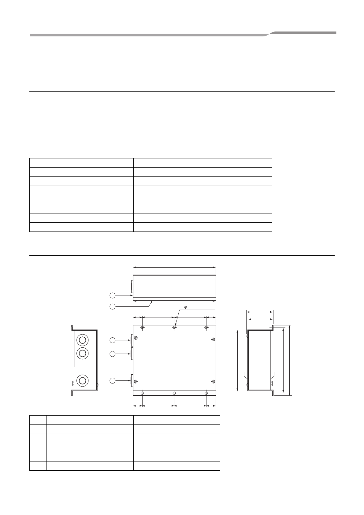
Dimensions 66 (H) x 170 (W) x 200 (D) mm
Mass 1 kg
External View
200
1
2
3
4
5
Parts name Specifications
1 Case Galvanized sheet metal
2 Case lid Galvanized sheet metal
3 Grommet C30-SG20A
4 Grommet C30-SG20A
5 Grommet for power supply C30-SG20A
6- 5.5 mounting holes
22787822
22787822
147
Top side
66
63.6
156
170
Bottom side
3 (EN)
Page 4

TCS-NET Relay Interface
Installation Manual
3 Before Installation
Check the following package contents.
No. Item Quantity Remarks
1 TCS-NET Relay Interface 1
2 Installation Manual 1
3 Screw 4 M4 x 12mm tapping screws
Leaflet (Caution for exchanging
4
product)
Use the following wiring materials to connect the signal lines and power lines. (Procured on site)
No. Line Description
1 For TCC-LINK
2 For RS-485
3 For power
1
Type 2-core shield wires
2
Wire size 1.25 mm
Length
Type 2-core shield wires
Wire size
Length
Type
Wire size
2.00 mm
(total length including air conditioner area)
1.25 mm
(total length)
H07 RN-F or 245IEC66
0.75mm
, 1000m max.
2
, 2000m max.
2
, 500m max.
2
, 50 m max.
4 (EN)
Page 5

TCS-NET Relay Interface
m
Installation Manual
4 Installation
TCS-NET Relay Interface Installation Method and Orientation
There are five installation methods for this relay interface as shown below: surface mount and wall mounts. Use
the attached screws.
No good
REQUIREMENT
Do not install the unit in any of the following places.
• Humid or wet place
• Dusty place
• Place exposed to direct sunlight
• Place where there is a TV set or radio within one meter
• Place exposed to rain (outdoors, under eaves, etc.)
Installation Space and Maintenance Space
A side space for connecting through cable inlets and an upper space for maintenance
must be reserved before installation.
The other sides can be adjacent to surrounding objects.
100mm
100m
5 (EN)
Page 6

TCS-NET Relay Interface
1
O
N
ON
3
1 2
4
2
Installation Manual
5 Connection of Power cables/Earth wires/
Signal wires
CAUTION
• The RS-485 signal lines have polarity. Connect A to A, and B to B. If connected with incorrect polarity, the unit will
not work.
• The TCC-LINK signal lines have no polarity.
Power cables/Earth wires/Signal wires
Connect power cables, earth wires, and signal wires to the specified terminals on the terminal block.
Secure each cable
with a cable clamp.
Air conditioner
Intelligent server
or Touch Screen
Controller
Connect the earth
wire to the earth
terminal on the
chassis.
Power supply
220V-240VAC
(50/60Hz)
Connect the shield wire of the
TCC-LINK communication wire
to the earth on the air conditioner
side. Do not connect the shield
wire to the terminal block. It
should be open and insulated.
FG
U2 U1
TCC- LINK
RS-485
BA
SW5
ON
1234
LN
Connect the shield wire of the
RS-485 communication wire to
the earth on the host system
side. Do not connect the shield
wire to the terminal block. It
should be open and insulated.
SW6
ON
12
LED5
LED4
LED3
LED2
SW7 LED1
SW4
SW2 SW3
SW1
Connect the power
supply cable and
earth wire to the
terminals using ring
terminals with
Length of stripped power
cable
Length of stripped RS-485
communication wire
insulation sleeve.
REQUIREMENT
Disconnect the appliance from the main power supply.
This appliance must be connected to the main power supply by a circuit breaker or switch with a contact separation
of at least 3mm.
Fasten the screws to the terminal with torque of 0.5Nm.
6 (EN)
Page 7

TCS-NET Relay Interface
Installation Manual
Wiring Connection
The following describes a connection example when using two or more TCS-NET Relay Interface units.
Terminator resistor setting (See “6 Setting” for the setting method.)
• Set the RS-485 terminator resistor to “Resistor set (120 ohm)” for No.1 (relay interface address SW1=1) TCSNET Relay Interface unit, and set to “open” for other units.
• Set the TCC-LINK terminator resistor to “open” as it is set on the air conditioner side.
Shield earthing
• The shield of RS-485 signal wires should be connected at closed end, and the terminal end should be open and
insulated. The shield earth of the RS-485 signal wires should be single-point earth at the host system.
The shield earth of the RS-485 signal wires should be single-point earth.
• The shield of TCC-LINK signal lines should be connected at the closed end, and the TCS-NET Relay Interface
terminal end should be open and insulated. Earth is connected on the air conditioner side.
TOUCH SCREEN CONTROLLER
INTELLIGENT SERVER
TCC-LINK U1 and U2
have no polarity.
Connect the shield
wires of the two
wires.
Red/Orange
Brown/YellowAB
A
B
Orange Brown
YellowRed
Crimp 3 wires
with a closed
end wire joint.
The shield of RS-485 cable should be
open and insulated. It is not connected
to the terminal block.
CAUTION: RS-485 signals A and B
have polarity. Be careful when
connecting the RS-485 wires.
Power supply
Power supply
The shield of TCC-LINK
cable should be open
and insulated. It is not
connected to the
terminal block.
SW6
FG
U1U2
TCC-LINK
ABLN
RS-485
SW5
SW6
FG
U1U2
TCC-LINK
ABLN
RS-485
SW5
ADDRESS
ADDRESS
TCC-LINK terminator resistor is set
on the air conditioner side. Bit 1 and
2 of SW6 should be OFF.
Set the RS-485 terminator resistor
on the No.1 unit (relay interface
address SW1=1) and host system.
Do not set it here.
Outdoor
SW1
SW1
unit
Remote
controller
Outdoor
unit
Remote
controller
Indoor unit
Indoor unit
8
1
Indoor unit
Indoor unit
Outdoor
unit
Remote
controller
Outdoor
unit
Remote
controller
Indoor unit
Indoor unit
Central
remote controller
Central
remote controller
RS-485 terminator resistor is set by relay interface of address
setting switch SW1=1 only. Set pull-up resistor and pull-down
resistor as well. Turn bit 1, 2 and 3 of SW5 ON.
7 (EN)
Set the TCS-NET Relay Interface address with
SW1. Assign 1 to 8 to each address to avoid
duplication.
CAUTION: The SW1 setting is read when the
power is turned on. Push the reset switch SW7
after changing the address.
Page 8

TCS-NET Relay Interface
Installation Manual
6 Setting
The following settings are necessary to use TCS-NET Relay Interface.
• SW1 TCS-NET Relay Interface address set switch
When two or more TCS-NET Relay Interface are used, set a different address for SW1 to avoid address
duplication.
Assign addresses in an ascending order.
CAUTION
• Set relay interface addresses according to the air conditioner address table.
For the relay interface whose address SW1=1, perform terminator resistor setting.
• When the SW1 setting has been changed, push the reset switch SW7. The new address setting is read.
• SW2 Test switch
• SW3 Test switch
• SW4 Test switch
Not used during operation.
Set these switches to zero (0) or “all OFF”.
• SW5 RS-485 terminator resistor select switch
Set “Resistor set (120 ohm)” only when the
relay interface address SW=1, and set “open”
for other relay interfaces.
FGU1U2ABLN
RS-485 TCC-LINK
1ON2 34
SW5
SW6
ON
1
2
SW7
LED4
LED2
LED5LED3LED1
1
234
• SW6 TCC-LINK terminator resistor select switch
The TCC-LINK terminator resistor is set on the
air conditioner side. Set SW6 to “open”.
• SW7 Reset switch
When performing an address setting with SW1,
push this reset switch after the address setting
to read the set value.
SW1 Relay interface address set switch
SW4
ON
SW3
SW2
SW1
1-8 Relay interface address
0, 9-F Not used
SW2 Test switch (0 usually)
SW3 Test switch (all OFF usually)
SW4 Test switch
SW5 RS-485 terminator resistor select switch
1ON2 34 1ON2 34
Resistor Set Open
SW6 TCC-LINK terminator resistor select switch
Bit1: pull-up resistor select.
Bit2: pull-down resistor select.
Bit3: terminator resistor select.
Bit4: terminator resistor select.
1ON2 1ON2
100 ohm Open
SW7 Reset switch
LED1 Power indicator
LED2 RS-485 communication status indicator
LED3 TCC-LINK Communication status indicator
LED4 TCC-LINK Communication error indicator
LED5 Test indicator
Note:Bit 2 is not used.
REQUIREMENT
• RS-485 terminator resistor select switch SW5.
Set “Resistor set (120 ohm)” (bit1, 2, 3 ON) only when the TCS-NET Relay Interface address SW=1, and
set “open” for other relay interfaces.
• The TCC-LINK terminator resistor is set on the air conditioner side. Set SW6 to “open”.
8 (EN)
Page 9

TCS-NET Relay Interface
Installation Manual
7 Trial Operation Check
Before starting trial operation
Complete the air conditioner trial operation.
Turn on the power of the TCS-NET Relay Interface after all cable connections and settings are completed.
Then turn on power of the Touch Screen Controller or intelligent Server.
Trial operation
Check the TCC-LINK and RS-485 communication status of the TCS-NET Relay Interface by checking the blinking
of the LEDs.
CAUTION
For the operation check of the Touch Screen Controller, refer to the Touch Screen Controller Installation Manual.
LED Normal operation Abnormal operation
LED1 Power indicator ON OFF
LED2 RS-485 communication status indicator Blinking OFF
LED3 TCC-LINK communication status indicator Blinking OFF
LED4 TCC-LINK communication error indicator OFF ON
LED5 TEST indicator OFF ON
LED1 Power indicator
ON: While power is on
OFF: When power is not turned on
LED2 RS-485 communication status indicator
Blinking: When RS-485 communication with the host system is normal
OFF: When RS-485 communication with the host system is disabled
LED3 TCC-LINK communication status indicator
Blinking: When TCC-LINK communication with any of the air conditioners is normal
OFF: When TCC0-LINK communication with all air conditioners is disabled
LED4 TCC-LINK communication error indicator
ON: While TCS-NET Relay Interface cannot send signals due to busy communication on the air conditioner
side. This status is temporary. This LED turns OFF after a while and communication will restart.
OFF: When communication of the air conditioner side is not busy
LED5 Test indicator
Not used in normal operation
Displayed only in the test mode
Trademarks
• BACnet is a registered trademark of ASHRAE (American Society of Heating, Refrigerating and Air-Conditioning
Engineers, Inc.).
9 (EN)
Page 10

DH69609103-1
 Loading...