

Toshiba Black Pear Installation And User Manual

BMS Interface for
Toshiba
Air-Conditioning
Installation and User Guide
www.microtrol.co.uk

BACnetTMis a registered trademark of ASHRAE (American Society of Heating,
Refrigerating and Air-Conditioning Engineers, Inc.)

1
Contents
1. Supplied Parts........................................................................................................................2
2. Important Information............................................................................................................ 3
3. Product Overview ..................................................................................................................4
3.1 Product Variants.............................................................................................................................4
4. Connection Details.................................................................................................................5
4.1 Power Supply .................................................................................................................................5
4.2 HVAC Communications Network ( TCC-LINK )...............................................................................5
4.3 Serial Communications Ports..........................................................................................................6
4.4 Digital Input / Output.......................................................................................................................7
4.5 USB................................................................................................................................................7
4.6 Ethernet..........................................................................................................................................7
5. Air-Conditioning Address Configuration............................................................................. 8
6. User Interface ( Display Version )....................................................................................... 10
6.1 Main Menu....................................................................................................................................11
6.2 System Overview..........................................................................................................................12
6.3 Unit Status Screen........................................................................................................................13
7. Modbus Interface ................................................................................................................. 14
7.1 Port Configurations.......................................................................................................................14
7.2 HVAC Status and Control Registers .............................................................................................15
7.3 Additional Register Usage ............................................................................................................16
7.4 Parameter Settings.......................................................................................................................17
7.5 Modbus Table Overview ...............................................................................................................18
8. Trend Interface (TT-64x only).............................................................................................. 20
8.1 Trend Process Description............................................................................................................21
8.2 Trend IQx Outstation Configuration ..............................................................................................22
8.3 Parameter Settings.......................................................................................................................23
9. BACnet Interface (TB-64x only) .......................................................................................... 24
9.1 Object Types ................................................................................................................................25
9.2 Service List...................................................................................................................................25
9.3 Object List ....................................................................................................................................26
9.4 Object Names...............................................................................................................................28
9.5 System Objects ............................................................................................................................29
Appendix A : Physical Dimensions........................................................................................ 30
Appendix B : Reset Button and Factory Defaults ................................................................. 31
Appendix C : Trend Outstation Memory Usage (TT-64x only) .............................................33
Appendix D : Toshiba Error Code Cross-Reference.............................................................35
Appendix E : Document Revision History .............................................................................37

2
1. Supplied Parts
or
Black Pear with display Black Pear without display
USB cable
Cat-5 ‘Straight-Through’
Ethernet cable
DIN-rail clips

3
2. Important Information
All electrical work should be carried out by a competent person and wiring must
be in accordance with the national electrical installation regulations.
Ensure that installation work is done correctly using the information contained in
this manual.
Make all connections securely
so that any outside forces acting on the cables are
not applied to the terminals.
Never modify or repair the Black Pear by yourself.
Any attempt to do so will void the warranty.
To dispose of this product, consult your dealer.
This unit will require setting up, using the free configuration software
available on our website.
Please go to www.microtrol.co.uk and click on the ‘Support’ link.
4
3. Product Overview
The Black Pear allows a building management system (BMS) to monitor and control airconditioning units on a Toshiba air-conditioning system without the need for a central
controller.
The unit incorporates a port which allows direct connection to the Toshiba TCC-LINK network
and allows up to 64 groups to be monitored and controlled.
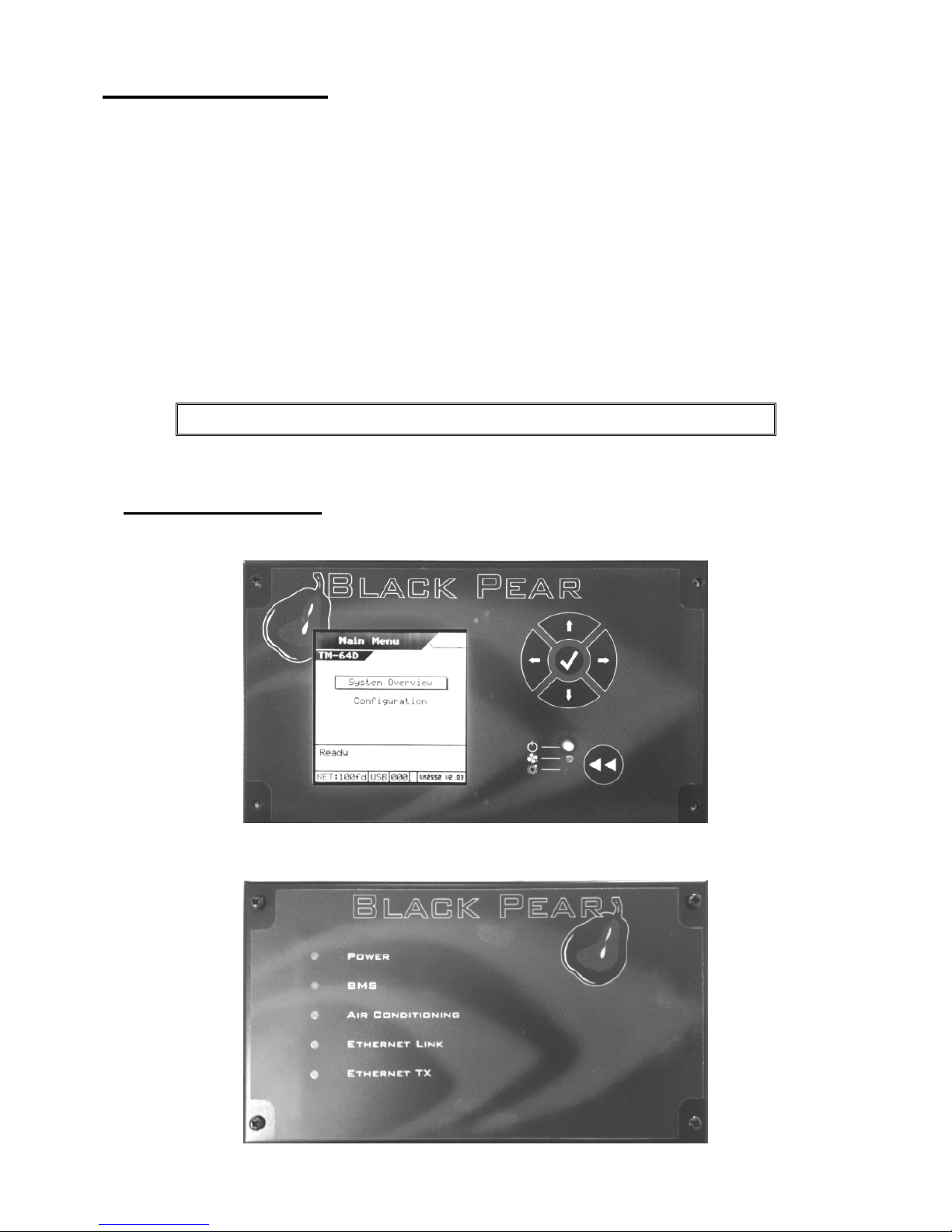
There are 2 hardware variants, one with an LCD display and one with LED indicators. The
display version also includes a simple keypad. providing convenient local control.
There are 3 models, each available with or without a display, providing different protocol
solutions:
TM-64,TM-64D Modbus RTU via RS232 / RS485 and Modbus/TCP.
TB-64,TB-64D BACnet/IP.
TT-64,TT-64D Trend via ethernet. (Also requires an IQ3/4 outstation with spare memory).
The BACnet and Trend models also have Modbus available
The Black Pear can also be used on systems where a central controller is already present.
3.1 Product Variants
With Display
Without Display

5
4. Connection Details
All electrical work should be carried out by a competent
person and wiring must be in accordance with the national
electrical installation regulations.
4.1 Power Supply
The Black Pear requires a 24v AC supply and has a consumption not exceeding 5VA. The
internal fuse is rated T630mA.
THIS EQUIPMENT MUST BE EARTHED
4.2 HVAC Communications Network ( TCC-LINK )
Connect to outdoor unit terminals U3 and U4, as per a standard central controller.
These are non-polarized.
Reset
Button
Power
Supply
HVAC Serial Comm
Ports
Digital
In/Out
24v AC
N/C
USB 10/100
Base-T
Ethernet
To
Ethernet
RS485-B
RS485-A
Out
In
RS232 Tx
RS232 Rx
Common
To HVAC Network
To PC
for configuration
and firmware
upgrading.
RS485-Com
Fig. 1 Connection Details
6
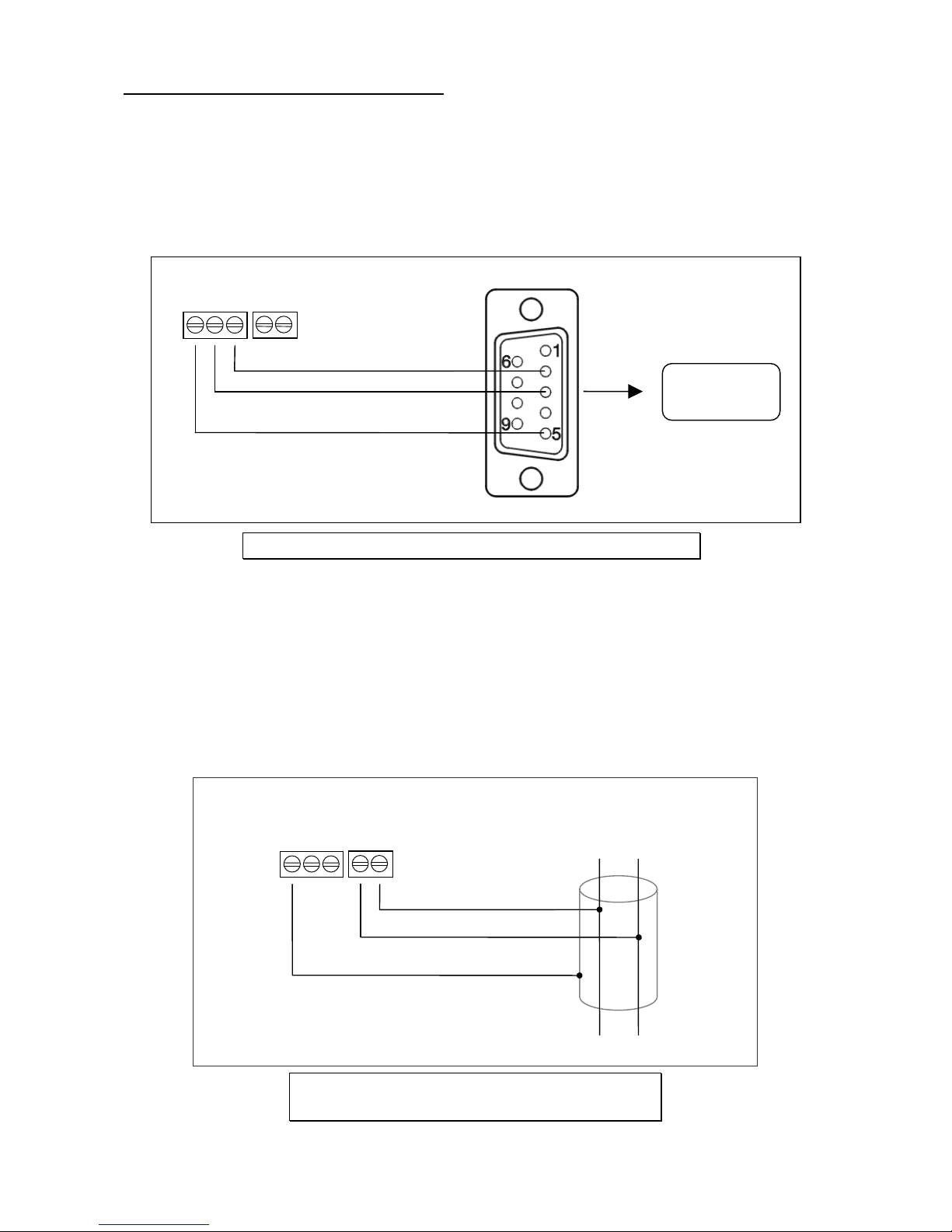
4.3 Serial Communications Ports
These connectors provide access to the Modbus registers using RS232 or 2-wire RS485.
The port configuration is as follows:
Modbus RTU
9600 baud, 8 data bits, no parity, 1 stop bit
The RS485 interface can be used on a compatible serial communications network shared
by multiple RS485 devices. The ‘Base Slave Address’ must be set to prevent multiple units
using the same slave numbers.
It is recommended that screened twisted-pair cable is used.
RS485-A is the non-inverting signal and is also named RS485+
RS485-B is the inverting signal and is also named RS485Common should be connected to the cable screen.
Serial Comms
Port
Pin 5
Pin 3
Pin 2
To PC
Comm Port
9
PIN D
-
S
UB FEMALE
Serial Comms
Port
RS485-B
RS485-A
RS485
network
Common
A B
Fig. 2 RS232 Comms Lead Wiring Diagram
Fig. 3 RS485 Comms Lead Wiring
Diagram

7
4.4 Digital Input / Output
As of firmware v2.27, the digital input functions as the ‘Global Forced Off’ signal. This is a
normally-closed, volt-free signal.
Upon detecting an ‘Open’ input, all available fancoils will be switched off and their remotecontrollers will be inhibited. These settings are refreshed every 10 seconds while the input
is ‘Open’.
When the input is subsequently ‘Closed’, the remote-controller inhibits are removed, but
the fancoils remain off.
The digital output currently has no functionality.
4.5USB
The USB interface is used for configuration via a PC and for upgrading the firmware.
Ensure that the correct USB driver has been installed prior to
connecting the Black Pear to a PC.
4.6 Ethernet
The Black Pear is a 10/100Base-T half/full duplex device. It supports auto-negotiation and
also features auto-crossover (Auto-MDIX), allowing the use of either a straight-through or
crossover cable.
It does not currently support DHCP and will therefore require the IP address, gateway
address and subnet-mask configuring to match the host network it is attached to.
If the unit is only being accessed via the local network then set the gateway address to be
the same as the IP address, otherwise enter the address of the appropriate gateway or
router.

8
5. Air-Conditioning Address Configuration
VRF
Outdoor
(System
Address 1)
Indoor Unit
(DN 03 = 1)
Indoor Unit
(DN 03 = 2)
Indoor Unit
(DN 03 = 3)
VRF
Outdoor
(System
Address 2)
Indoor Unit
(DN 03 = 4)
Indoor Unit
(DN 03 = 5)
Indoor Unit
(DN 03 = 6)
Split System Indoor
Unit
(System Address 3
DNO3 =7)
Black Pear
U1/U2
U1/U2
U3/U4
U3/U4
*TCB-PCNT30TLE2 Network Adapter required for some Split Indoor units.
Fig. 4 Addressing Example

9
The systems need to be set up as if a standard Toshiba central controller is to be fitted. The
Black Pear can replace or work in parallel with a Toshiba central controller.
Each refrigerant system must have a separate line address and the network address
(Configuration Item 03) must be set between 1 and 64. If units are grouped via AB, the units
will have the same network address and the status data for the follower units will not be
available.
Units can be grouped within the Black Pear using the PC configuration software. The
groupings determine which unit addresses can accept commands from the BMS system.
The group number is defined as ‘the lowest indoor unit address within the group’. This then
becomes the ‘master’ address for the group, and is the only address within that group that
can accept commands.
The other units within a group can be classed as ‘slave’ units and contain the same status
parameter values as the ‘master’, apart from Return Air Temp and Error Code, which are
unique to each unit.
Attempting to write a command to a ‘slave’ unit will have no effect.
If you wish to be able to monitor slave units within a group, ensure that they are configured
as individual units (via the A/C system) and grouped using the Black Pear.
10
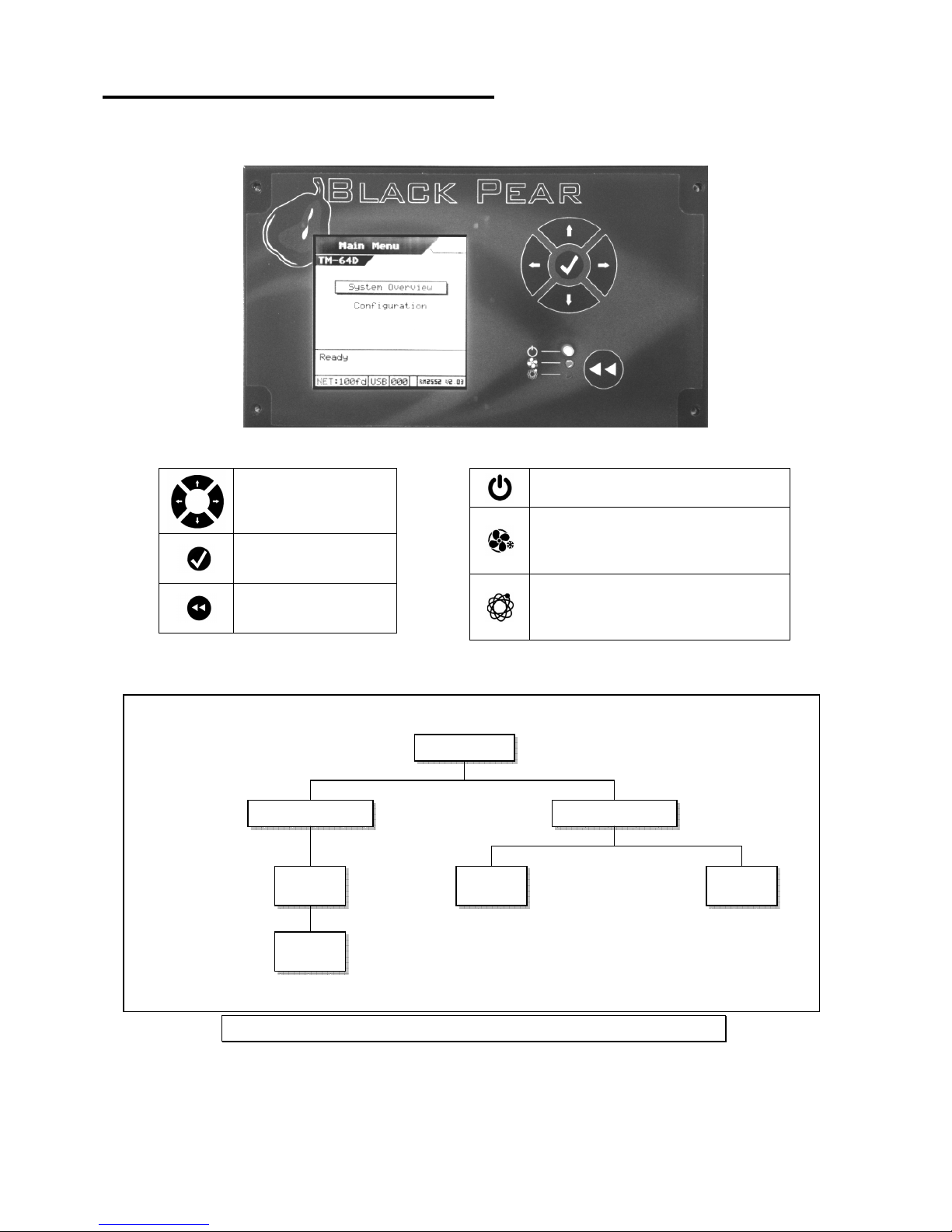
6. User Interface ( Display Version )
Navigation Buttons
Enter/Accept Button
Back/Cancel Button
Power LED
HVAC Network LED
Flashes on a valid incoming
message
BMS Network LED
Flashes on a valid incoming
message
Main Menu
System Overview Configuration
Modbus Network
Unit
Status
Unit
Control
Fig. 5 Screen Hierarchy
 Loading...