

Page 1

Copyright © 2014 TOSHIBA TELI CORPORATION, All rights reserved. http://www.toshiba-teli.co.jp/index.htm
D4235067D
BG Series
CMOS Camera
Instruction Manual
Model
B/W Camera : BG205M-CS
Color Camera : BG205MC-CS / BG205MCF-CS
Information contained in this document is subject to change without prior notice.
Thank you for purchasing our product.
Before using this CMOS camera, Please read through this instruction
manual carefully in order to use this product correctly and safely.
After reading, keep this instruction manual handy so that you can refer to,
whenever you need it.
Page 2

1 / 80
Copyright © 2014 TOSHIBA TELI CORPORATION, All rights reserved. http://www.toshiba-teli.co.jp/index.htm
D4235067D
1. Contents
1. Contents .................................................................................................................... 1
2. Safety Precautions .................................................................................................... 2
General Handing ............................................................................................................................. 3
CASES FOR INDEMNITY (LIMITED WARRANTY) ....................................................................... 5
RESTRICTION FOR USE............................................................................................................... 6
Notes on using this product ............................................................................................................ 7
3. Installation ............................................................................................................... 12
4. Specifications .......................................................................................................... 13
Overview ....................................................................................................................................... 13
Features ........................................................................................................................................ 13
Configuration ................................................................................................................................. 15
Connection .................................................................................................................................... 16
Connector Pin Assignment ........................................................................................................... 17
Outline Drawing ............................................................................................................................ 19
General Specifications .................................................................................................................. 20
I/O Specification ............................................................................................................................ 22
Timing Specification ...................................................................................................................... 27
Typical Spectral Response ........................................................................................................... 30
Operating Ambient Conditions ...................................................................................................... 32
5. Functions ................................................................................................................. 33
DeviceControl................................................................................................................................ 35
Scalable ........................................................................................................................................ 36
Decimation .................................................................................................................................... 38
Reverse ......................................................................................................................................... 40
PixelFormat ................................................................................................................................... 41
TestImageSelector ........................................................................................................................ 42
AcquisitionControl ......................................................................................................................... 44
TriggerControl ............................................................................................................................... 46
ExposureControl ........................................................................................................................... 51
DigitalIOControl ............................................................................................................................. 53
TimerControl ................................................................................................................................. 55
EventControl ................................................................................................................................. 57
Gain ............................................................................................................................................... 60
BalanceRatio ................................................................................................................................. 62
BalanceWhiteAuto ........................................................................................................................ 64
BlackLevel ..................................................................................................................................... 65
Gamma ......................................................................................................................................... 66
BlackLevelCorrection .................................................................................................................... 67
LUTControl .................................................................................................................................... 68
TransportLayerControl .................................................................................................................. 69
UserSetControl.............................................................................................................................. 73
ALCControl .................................................................................................................................... 75
6. Warranty rules ......................................................................................................... 79
7. Repair ...................................................................................................................... 80
Page 3
2 / 80
Copyright © 2014 TOSHIBA TELI CORPORATION, All rights reserved. http://www.toshiba-teli.co.jp/index.htm
D4235067D
2. Safety Precautions
Before using this product, read these safety precautions carefully. Important information is shown in this
Instruction Manual to protect users from bodily injuries and property damages, and to enable them to use the
product safely and correctly.
Please be sure to thoroughly understand the meanings of the following signs and symbols before reading
the main text that follow, and observe the instructions given herein.
[Definition of Safety Signs]
Notes *1:“Serious injury” refers to cases of loss of eyesight, wounds, burns (high or low temperature),
electric shock, broken bones, poisoning, etc., which leave after-effects or which require
hospitalization or a long period of outpatient treatment of cure.
*2: "Light to moderate injuries" refers to injuries, burns, electric shock etc. that do not require
hospitalization or long-term treatment.
*3: "Property damage" refers to cases of extensive damage involving damage to buildings,
equipment, farm animals, pet animals and other belongings.
[Explanation of Safety Symbols]
Safety Signs
Description
WARNING
Indicates a potentially hazardous situation that may result in death or serious
injury (*1) in the event of improper handling.
CAUTION
Indicates a potentially hazardous situation that may result in light to moderate
injuries (*2) or only in property damage (*3)in the event of improper handling.
Safety Symbols
Description
PROHIBITED
This sign indicates PROHIBITION (Do not).
The content of prohibition is shown by a picture or words beside the symbol.
MANDATORY
This sign indicates MANDATORY ACTION (You are required to do).
The content of action is shown by a picture or words beside the symbol.
Page 4
3 / 80
Copyright © 2014 TOSHIBA TELI CORPORATION, All rights reserved. http://www.toshiba-teli.co.jp/index.htm
D4235067D
General Handing
WARNING
Stop operation immediately when any abnormality or defect occurs.
If abnormal conditions are present, such as smoke, a burning smell, ingress of water or
foreign matter, or if the equipment is dropped or malfunctions, fire or electric shock may
result.
Be always sure to disconnect the power cable from the wall socket at once and contact
your dealer.
Unplug
Do not use the equipment in locations subject to water splashes.
Otherwise, fire or electric shock may result.
Do not get wet
Do not disassemble, repair, or modify the equipment.
Otherwise, fire or electric shock may result.
For internal repair, inspection, or cleaning, contact your sales representative.
Never pull apart
Do not place anything on the equipment.
If metallic objects, liquid, or other foreign matter enters the equipment, fire or electric
shock may result.
Avoid
Do not install the equipment in an unstable or inclined location or locations
subject to vibration or impact.
Otherwise, the equipment may topple over and cause personal injury.
Avoid
During an electrical storm, do not touch the power cable and the connection
cable.
Otherwise, an electric shock may result.
Do not touch
Instruction
Use the specified voltage.
Use of an unspecified voltage may result in fire or electric shock.
Do not be handled roughly, damaged, fabricated, bent forcefully, pulled, twisted,
bundled, placed under heavy objects or heated the power cable and the
connection cable.
Otherwise, fire or electric shock may result.
Avoid
Page 5
4 / 80
Copyright © 2014 TOSHIBA TELI CORPORATION, All rights reserved. http://www.toshiba-teli.co.jp/index.htm
D4235067D
CAUTION
Observe the following when installing the equipment:
·Do not cover the equipment with a cloth, etc.
·Do not place the equipment in a narrow location where heat is likely to accumulate.
Otherwise, heat will accumulate inside the equipment, possibly resulting in a fire.
Instruction
Do not place the equipment in locations subject to high moisture, oil fumes,
steam, or dust.
Otherwise, fire or electric shock may result.
Avoid
Do not install the equipment in locations exposed to direct sunlight or humidity.
Otherwise, the internal temperature of the equipment will rise, which may cause a fire.
Avoid
Use only specified the power cable and the connection cables.
Otherwise, fire or electric shock may result.
Instruction
Do not give strong impact against the equipment.
It may cause the trouble.
Avoid
When performing connection, turn off power.
When connecting the power cable and the connection cable, turn off the equipment
power.
Otherwise, fire or electric shock may result.
Instruction
Do not expose its camera head to any intensive light (such as direct sunlight).
Otherwise, its inner image pickup device might get damaged.
Avoid
Avoid short-circuiting signal output.
Otherwise, a malfunction may occur.
Avoid
Avoid giving a strong shock against the camera body.
It might cause a breakdown or damage. If your camera is used in a system where its
camera connector is subjected to strong repetitive shocks, its camera connector is
possible to break down. If you intend to use your camera in such a situation, if possible,
bundle and fix a camera cable in the place near the camera, and do not transmit a
shock to the camera connector.
Avoid
Contact your sales representative to request periodic inspection and cleaning
(every approx five years).
Accumulation of dust inside the equipment may result in fire or electric shock.
For inspection and cleaning costs, contact your sales representative.
Instruction
Page 6

5 / 80
Copyright © 2014 TOSHIBA TELI CORPORATION, All rights reserved. http://www.toshiba-teli.co.jp/index.htm
D4235067D
CASES FOR INDEMNITY (LIMITED WARRANTY)
We shall be exempted from taking responsibility and held harmless for damage or losses incurred by the
user in the following cases.
● In the case damage or losses are caused by natural disasters, such as an earthquake and thunder, fire, or
other acts of God, acts by a third party, deliberate or accidental misuse by the user, or use under extreme
operating conditions.
● In the case of indirect, additional, consequential damages (loss of business interests, suspension of
business activities) are incurred as result of malfunction or non-function of the equipment, we shall be
exempted from responsibility for such damages.
● In the case damage or losses are caused by failure to observe the information contained in the
instructions in this instruction manual and specifications.
● In the case damage or losses are caused by use contrary to the instructions in this instruction manual and
specifications.
● In the case damage or losses are caused by malfunction or other problems resulting from unintended use
of equipment or software etc. that are not specified.
● In the case damage or losses are caused by repair or modification conducted by the customer or any
unauthorized third party (such as an unauthorized service representative).
● Expenses we bear on this product shall be limited to the individual price of the product.
● The item that is not described in specifications of this product is out of the guarantee.
● The case of damages or losses which are caused by incorrect connection of the cable is out of the
guarantee.
Page 7

6 / 80
Copyright © 2014 TOSHIBA TELI CORPORATION, All rights reserved. http://www.toshiba-teli.co.jp/index.htm
D4235067D
RESTRICTION FOR USE
● Should the equipment be used in the following conditions or environments, give consideration to safety
measures and inform us of such usage:
1. Use of the equipment in the conditions or environment contrary to those specified, or use outdoors.
2. Use of the equipment in applications expected to cause potential hazard to people or property, which
require special safety measures to be adopted.
● This product can be used under diverse operating conditions. Determination of applicability of equipment or
devices concerned shall be determined after analysis or testing as necessary by the designer of such
equipment or devices, or personnel related to the specifications. Such designer or personnel shall assure
the performance and safety of the equipment or devices.
● This product is not designed or manufactured to be used for control of equipment directly concerned with
human life (*1) or equipment relating to maintenance of public services/functions involving factors of safety
(*2). Therefore, the product shall not be used for such applications.
(*1): Equipment directly concerned with human life refers to.
- Medical equipment such as life-support systems, equipment for operating theaters.
- Exhaust control equipment for exhaust gases such as toxic fumes or smoke.
- Equipment mandatory to be installed by various laws and regulations such as the Fire Act or Building
Standard Law
- Equipment related to the above
(*2): Equipment relating to maintenance of public services/functions involving factors of safety refers to.
- Traffic control systems for air transportation, railways, roads, or marine transportation
- Equipment for nuclear power generation
- Equipment related to the above
Page 8
7 / 80
Copyright © 2014 TOSHIBA TELI CORPORATION, All rights reserved. http://www.toshiba-teli.co.jp/index.htm
D4235067D
Notes on using this product
● Handle carefully
Do not drop the equipment or allow it to be subject to strong impact or vibration, as such action may cause
malfunctions. Further, do not damage the connection cable, since this may cause wire breakage.
● Environmental operating conditions
Do not use the product in locations where the ambient temperature or humidity exceeds the specifications.
Otherwise, image quality may be degraded or internal components may be adversely affected. In particular,
do not use the product in areas exposed to direct sunlight. Moreover, during shooting under high
temperatures, vertical stripes or white spots (noise) may be produced, depending on the subject or camera
conditions (such as increased gain). However, such phenomena are not malfunctions.
● Check a combination with the lens
Depending on the lens and lighting you use, an image is reflected as a ghost in the imaging area. However,
this is not because of a fault of the camera.
In addition, depending on the lens you use, the performance of the camera may not be brought out fully due
to deterioration in resolution and brightness in the peripheral area, aberration and others.
Be sure to check a combination with the camera by using the lens and lightning you actually use.
When installing a lens in the camera, make sure carefully that it is not tilted.
In addition, use a mounting screw free from defects and dirt. Otherwise, the camera may be unable to be
removed.
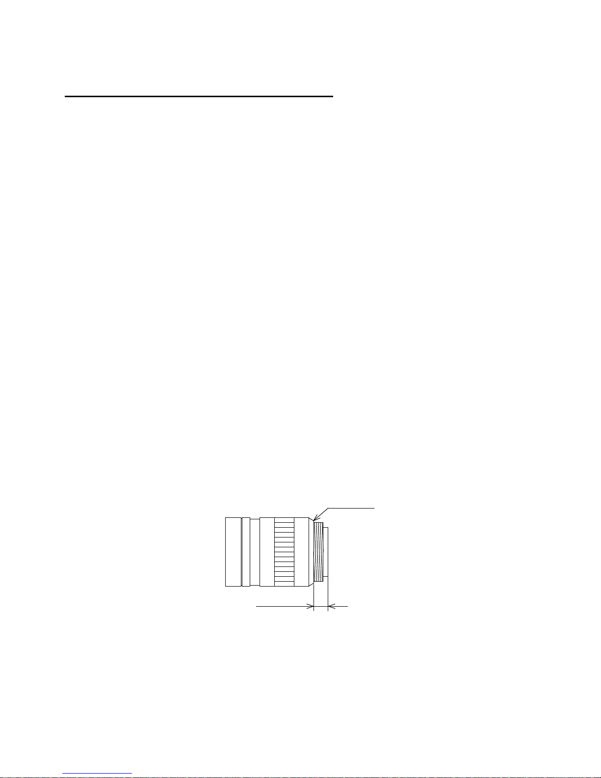
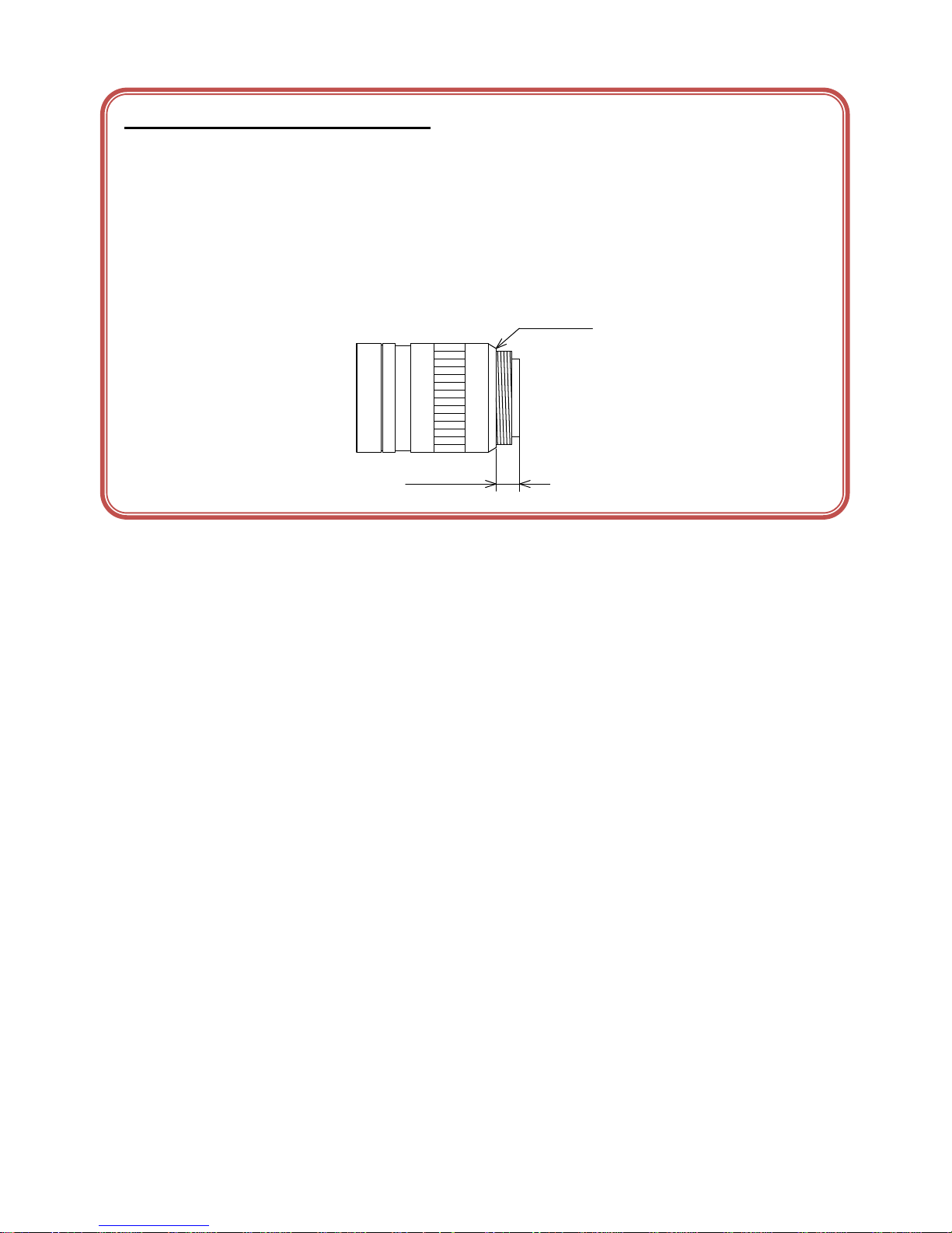
Install a next lens; its dimension of protrusion from bottom of the screw is equal to or less than 4.9 mm. If a
lens does not stand to this condition, it might not be installed to this camera.
4.9mm or less
CS-mount lens
Bottom of
the screw
● Mounting to pedestal
When mounting this product to a pedestal, make sure carefully that lens doesn’t touch with the pedestal.
Page 9

8 / 80
Copyright © 2014 TOSHIBA TELI CORPORATION, All rights reserved. http://www.toshiba-teli.co.jp/index.htm
D4235067D
● Do not expose the camera's image-pickup-plane to sunlight or other intense light directly
Its inner CMOS sensor might be damaged.
● Occurrence of moiré
If you shoot thin stripe patterns, moiré patterns (interference fringes) may appear. This is not a malfunction.
● Occurrence of noise on the screen
If an intense magnetic or electromagnetic field is generated near the camera or connection cable, noise may
be generated on the screen. If this occurs, move the camera or the cable.
● Handling of the protective cap
If the camera is not in use, attach the lens cap to the camera to protect the image pickup surface.
● If the equipment is not to be used for a long duration
Turn off power to the camera for safety.
● Maintenance
Turn off power to the equipment and wipe it with a dry cloth.
If it becomes severely contaminated, gently wipe the affected areas with a soft cloth dampened with diluted
neutral detergent. Never use alcohol, benzene, thinner, or other chemicals because such chemicals may
damage or discolor the paint and indications.
If the image pickup surface becomes dusty, contaminated, or scratched, consult your sales representative.
Page 10
9 / 80
Copyright © 2014 TOSHIBA TELI CORPORATION, All rights reserved. http://www.toshiba-teli.co.jp/index.htm
D4235067D
● Disposal
When disposing of the camera, it may be necessary to disassemble it into separate parts, in accordance
with the laws and regulations of your country and/or municipality concerning environmental contamination.
This product is marked this symbol to subject to EU Waste Electrical & Electronic Equipment (WEEE)
directive.
Following information is only for EU-member states:
The use of the symbol indicates that this product may not be treated as household
waste. By ensuring this product is disposed of correctly, you will help prevent
potential negative consequences for the environment and human health, which could
otherwise be caused by inappropriate waste handling of this product. For more
detailed information about the take-back and recycling of this product, please contact
your supplier where you purchased the product.
“This symbol is applicable for EU member states only”
This equipment has been tested and found to comply with the limits for a class A digital device,
pursuant to Part 15 of the FCC Rules.
These limits are designed to provide reasonable protection against harmful interference when the
equipment is operated in a commercial environment.
This equipment generates, uses, and can radiate radio frequency energy and, if not installed and
used in accordance with the instruction manual, may cause harmful interference to radio
communication.
Operation of this equipment in a residential area is likely to cause harmful interference in which case
the user will be require to correct the interference at his own expense.
Page 11

10 / 80
Copyright © 2014 TOSHIBA TELI CORPORATION, All rights reserved. http://www.toshiba-teli.co.jp/index.htm
D4235067D
[Phenomena specific to CMOS sensor]
Defective pixels
A CMOS image sensor is composed of photo sensor pixels in a square grid array. Due to
the characteristics of CMOS image sensors, over- or under-driving of the pixels results in
temporary white or black areas (as if these are noises) appearing on the screen. This
phenomenon, which is not a defect is exacerbated under higher temperatures and long
exposure time.
Image shading
The brightness of the upper part of the screen may be different from that of the lower part. Note
that this is a characteristic of a CMOS image sensor and is not a fault.
Page 12
11 / 80
Copyright © 2014 TOSHIBA TELI CORPORATION, All rights reserved. http://www.toshiba-teli.co.jp/index.htm
D4235067D
环保使用期限标识,是根据电子信息产品污染控制管理办法以及,电子
信息产品污染控制标识要求(SJ/T11364-2006)、电子信息产品环保使用
期限通则,制定的适用于中国境内销售的电子信息产品的标识。
电子信息产品只要按照安全及使用说明内容,正常使用情况下,从生产
月期算起,在此期限内,产品中含有的有毒有害物质不致发生外泄或突
变,不致对环境造成严重污染或对其人身、财产造成严重损害。
产品正常使用后,要废弃在环保使用年限内或者刚到年限的产品时,请
根据国家标准采取适当的方法进行处置。
另外,此期限不同于质量/功能的保证期限。
The Mark and Information are applicable for People's Republic of
China only.
<产品中有毒有害物质或元素的名称及含量>
部件名称
有毒有害物质或元素
铅(Pb)
汞(Hg)
镉(Cd)
六价铬
(Cr(VI))
多溴联苯
(PBB)
多溴二苯醚
(PBDE)
相机本体
× ○ ○ ○ ○
○
○:表示该有毒有害物质在该部件所有均质材料中的含量均在电子信息产品中有毒有害物质的
限量要求标准规定的限量要求(SJ/T11363-2006)以下
×:表示该有毒有害物质至少在该部件的某一均质材料中的含量超出电子信息产品中有毒有害
物质的限量要求标准规定的限量要求(SJ/T11363-2006)
This information is applicable for People's Republic of China only.
リサイクルに関する情報(包装物)
有关再利用的信息(包装物)
Information on recycling of wrapping composition
中华人民共和国
环保使用期限
10
ペーパーボード
纸板
Paper board
箱/箱子/Box
内部緩衝材料・袋
内部缓冲材料·袋
Internal buffer materials・Bag
Page 13

12 / 80
Copyright © 2014 TOSHIBA TELI CORPORATION, All rights reserved. http://www.toshiba-teli.co.jp/index.htm
D4235067D
3. Installation
Before using this product, you shall install application software to display image and control registers of
camera, and IP configuration tool for network setting.
You can download the SDK for our GigE camera products (TeliGevSDK) from the Service & Support section
of our website.
User registration is necessary to use downloading service. Please make a user registration, or contact your
dealer / distributor.
● TOSHIBA TELI CORPORATION Top Page
http://www.toshiba-teli.co.jp/index.htm
● Service & Support
https://www.toshiba-teli.co.jp/cgi/ss/en/service.cgi
Please refer to the TeliGevSDK startup guide, about Operation environment, Installation, and Setup.
Page 14

13 / 80
Copyright © 2014 TOSHIBA TELI CORPORATION, All rights reserved. http://www.toshiba-teli.co.jp/index.htm
D4235067D
4. Specifications
Overview
This BG series is an integrated-(one-body)-type monochrome and color camera that adopts a global shutter
CMOS sensor. BG205M-CS (2M 2/3 type, monochrome), BG205MC-CS (2M 2/3 type, color) and
BG205MCF-CS (2M 2/3 type, color, IR-cut).
For video output, the Gigabit Ethernet®* interface standard "IEEE802.3ab" is adopted for high transfer rate,
and it is easy to integrate into industrial equipment.
* Ethernet® is a registered trademark of XEROX Corporation.
Features
● High frame rate and high resolution
Supported high frame rate, BG205M/C/CF-CS 50fps.
● Global shutter
As it employs a global electronic shutter similar to a CCD image sensor, clear images of even fast-moving
object are obtainable with less blur.
● Gigabit Ethernet interface (Power over Ethernet)
Video output and camera control are performed via the Gigabit Ethernet standard IEEE802.3ab interface.
Data transfer is up to 1Gbps (Maximum) that enables to output uncompressed video data at high frame rate.
By complying with IEEE802.3af Power over Ethernet (PoE), the power is supplied over single cable.
● GigEVision Ver 1.2 conformity
This product is based on GigEVision Camera Interface Standard for Machine Vision Ver 1.2.
● GenICam Ver 2.3 conformity
This product is based on GenICam Generic Interface for Cameras Ver 2.3.
Page 15

14 / 80
Copyright © 2014 TOSHIBA TELI CORPORATION, All rights reserved. http://www.toshiba-teli.co.jp/index.htm
D4235067D
● Random Trigger Shutter
The Random Trigger Shutter function provides images in any timing by input of an external trigger signal.
Trigger control from PC is available as well.
● Scalable
Selectable video output area. This mode achieves higher frame rate by reducing vertical output area. And
reduces occupied data rate of Gigabit Ethernet by reducing horizontal output area.
● Decimation mode
Camera reads all effective areas at high speed by skipping lines.
● Color processing
Color models have built in color processing. Color processing features like white balance are available in
Bayer output mode.
● IR-cut filter
Build-in IR-cut filter models are optional for color models.
The character [F] of the model name indicates the built-in IR-cut filter model. (e.g. BG205MCF-CS)
* The character [F] is not shown in the common part of specifications.
● Compact and lightweight
This camera is compact and lightweight; it is easy to integrate into industrial equipment.
● EU RoHS & Chinese ROHS
Page 16

15 / 80
Copyright © 2014 TOSHIBA TELI CORPORATION, All rights reserved. http://www.toshiba-teli.co.jp/index.htm
D4235067D
Configuration
The system configuration of this camera series is as follows;
This camera does not include any accessories. Please prepare other equipments separately.
● Camera: This product. (BG series)
● Camera mounting kit CPT8600 (*1): To fix a camera to a tripod; attach this to the bottom of the
camera.
● LAN Cable (*2): This cable is used to connect the camera to host equipment.
Ethernet packets (stream and control) are transmitted via this
cable. Please use a LAN cable that supports 1000BASE-T (Cat
5e or over). This product is able to connect a LAN cable that is
equipped with screw lock mechanism. Please use it as needed.
● Network Interface Card (NIC) (*2): This is the interface card to connect to the camera. Usually this
card is installed to expansion slot of host equipment such as PC
etc. Please use 1000BASE-T NIC, supporting Jumbo Frame is
recommended.
● PoE Switching HUB etc. (*2): Use these equipments when you supply power to the camera
from PoE. Please use 1000BASE-T equipments, supporting
Jumbo Frame is recommended.
*1: Optional part. Contact your dealer / distributor for details of option units.
*2: Commercial items.
Page 17
16 / 80
Copyright © 2014 TOSHIBA TELI CORPORATION, All rights reserved. http://www.toshiba-teli.co.jp/index.htm
D4235067D
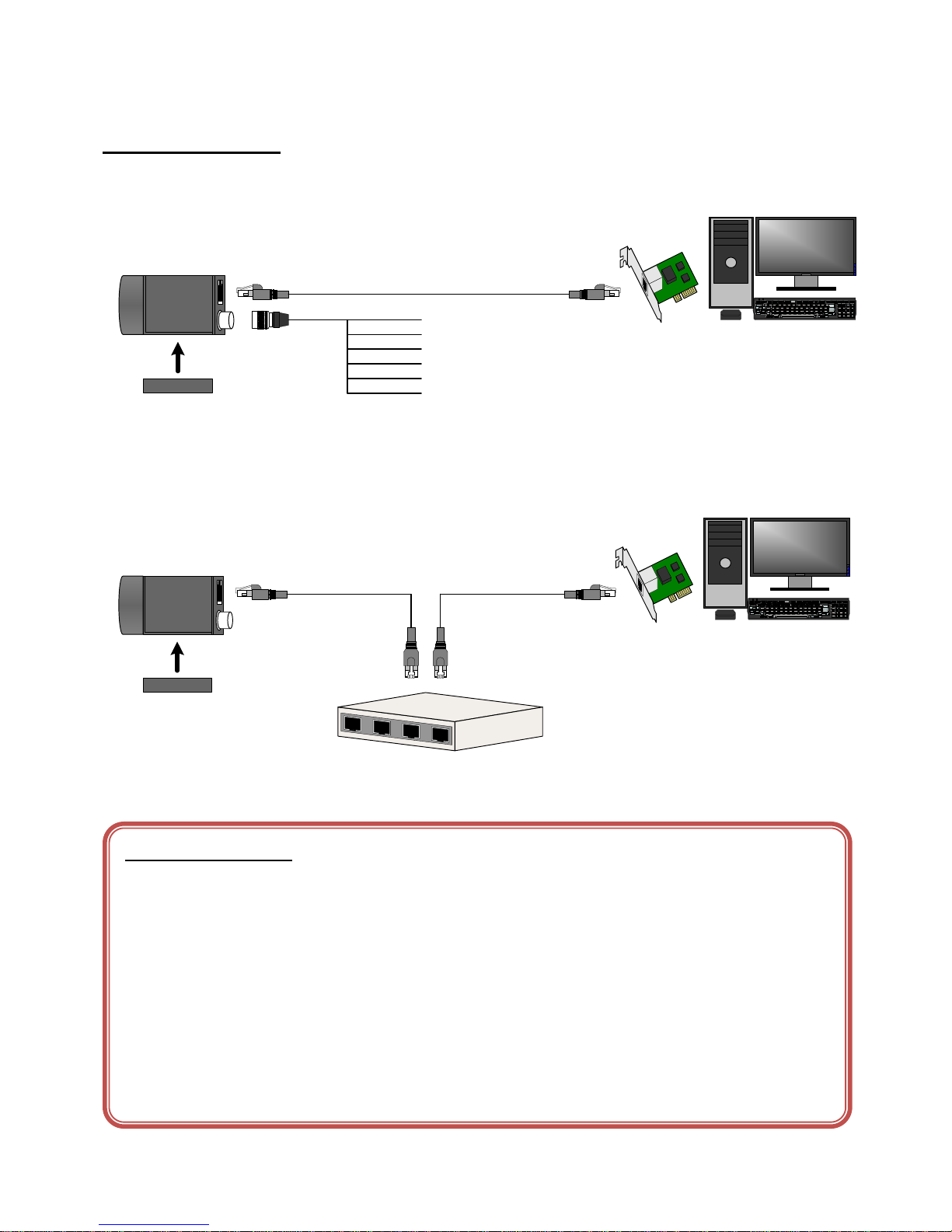
Connection
● In the case of supply DC+12V to the camera.
BG Series
Camera
Host (PC etc.)
Camera mounting kit
CPT8600
Network Interface
Card
Stream Packet →← Control Packet
LAN Cable
1. DC+12V IN
2. LINE0 IN
3. LINE1 OUT
4. LINE2 OUT
5. I/O GND
6. GND
● In the case of supply PoE power to the camera.
BG Series
Camera
Host (PC etc.)
Camera mounting kit
CPT8600
Network Interface
Card
Stream Packet →← Control Packet
← PoE Power
LAN Cable
PoE Switching HUB etc.
Fig.4-1 Connection
Notes on Connection:
- Please confirm the power supply of the camera off when plugging in or pulling out the I/O Connector. It causes the
breakdown.
- If your camera is used in a system where its connectors are subjected to strong repetitive shocks, its connectors are
possible to break down. If you use your camera in such a situation, use an LAN cable with a lock screw, and secure
the camera cable as close as possible to the camera body for avoid physical shock to the camera connector.
- About Camera cable: In the case that electric-wire is long or thin, input voltage may not satisfy specifications of the
power supply voltage of the camera by voltage drop. Please confirm it before use.
- Lost packets may occur by an electrical characteristic of the transmission line of using Ethernet devices (LAN cable,
Network Interface Card, Switching HUB).
Page 18
17 / 80
Copyright © 2014 TOSHIBA TELI CORPORATION, All rights reserved. http://www.toshiba-teli.co.jp/index.htm
D4235067D
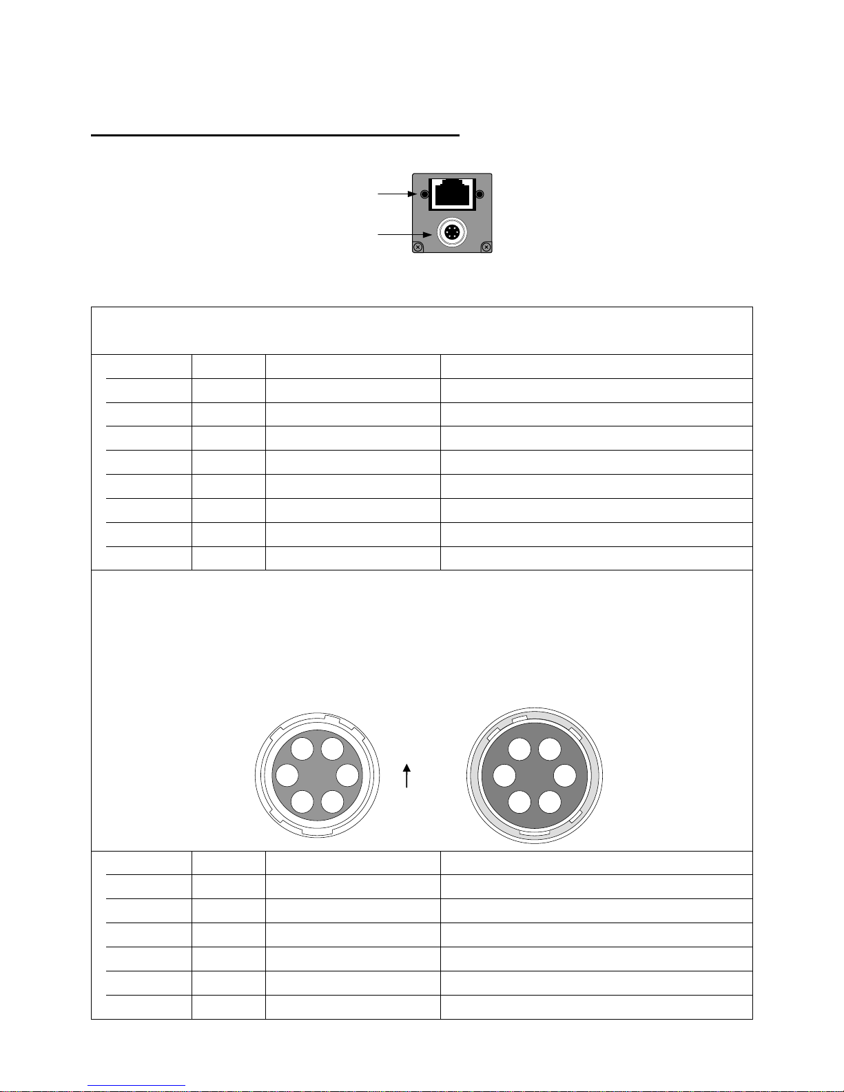
Connector Pin Assignment
1
2
Rear View
1. Gigabit Ethernet Interface Connector
RJ-45 Jack
Pin No.
I/O
Signal
Function
1 I/O
BI_DA+ / VDC+
Bidirectional Data A (+) / Power (+)
2 I/O
BI_DA- / VDC+
Bidirectional Data A (-) / Power (+)
3 I/O
BI_DB+ / VDC-
Bidirectional Data B (+) / Power (-)
4 I/O
BI_DC+ / VDC+
Bidirectional Data C (+) / Power (+)
5 I/O
BI_DC- / VDC+
Bidirectional Data C (-) / Power (+)
6 I/O
BI_DB- / VDC-
Bidirectional Data B (-) / Power (-)
7 I/O
BI_DD+ / VDC-
Bidirectional Data D (+) / Power (-)
8 I/O
BI_DD- / VDC-
Bidirectional Data D (-) / Power (-)
2. I/O Connector
Connector (Camera side) HR10A-7R-6PB(73) (HIROSE ELECTRIC CO., LTD.) or equivalency product
Plug (Cable side) HR10A-7P-6S(73) (HIROSE ELECTRIC CO., LTD.) or equivalency product
* This camera cable is not an accessory of this product.
Connector view from mating face
Pin No.
I/O
Signal
Function
1 I
+12V
Power
2 I
Line 0
External Trigger Input
3 O
Line 1
GPIO_0 Output (LVTTL)
4 O
Line 2
GPIO_1 Output (Open Collector)
5 -
I/O GND
I/O_Ground
6 -
GND
Ground
TOP
5
61
2
3 4
Cable side
2
16
5
4 3
Camera side
Page 19

18 / 80
Copyright © 2014 TOSHIBA TELI CORPORATION, All rights reserved. http://www.toshiba-teli.co.jp/index.htm
D4235067D
Notes on Power Supply:
This camera has two ways of power supply,
- Supply from LAN cable (PoE)
- Supply from camera cable (DC+12V ±10%)
If both PoE and DC+12V are connected, power is supplied from PoE.
Page 20
19 / 80
Copyright © 2014 TOSHIBA TELI CORPORATION, All rights reserved. http://www.toshiba-teli.co.jp/index.htm
D4235067D
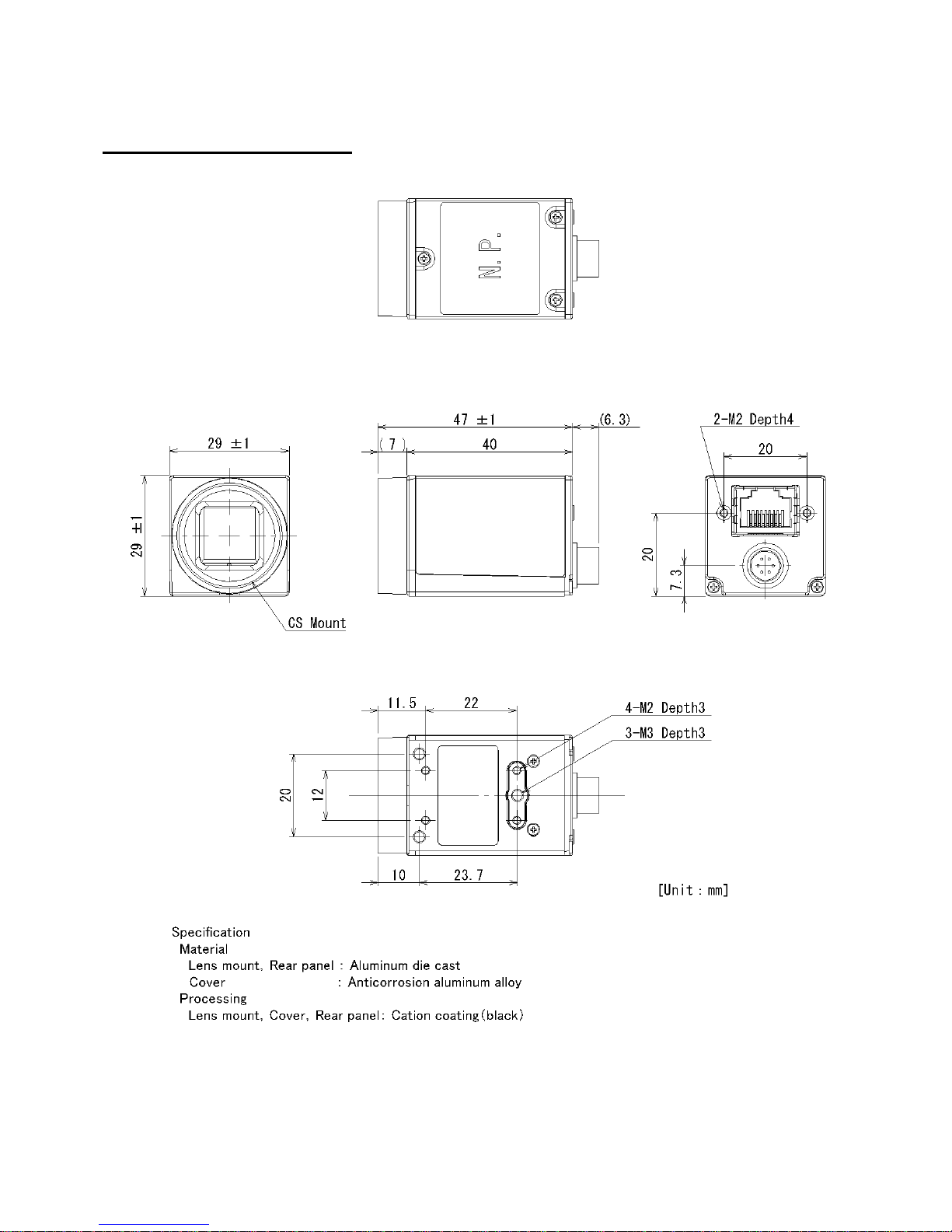
Outline Drawing
Fig.4-2 Outline Drawing
Page 21

20 / 80
Copyright © 2014 TOSHIBA TELI CORPORATION, All rights reserved. http://www.toshiba-teli.co.jp/index.htm
D4235067D
General Specifications
Table.4-1 Specifications
Model Name
BG205M-CS
BG205MC-CS
BG205MCF-CS
IR-cut filter
None
None
Built-in
Imager
CMOS image sensor
Number of effective pixels (H) × (V)
2048 × 1088
Optical Size
2/3 type
Scanning area (H) × (V)[mm]
11.26 × 5.98
Pixel size (H) × (V)[μm]
5.5 × 5.5
Scan method
Progressive
Electronic shutter method
Global shutter
Aspect ratio
2: 1
Sensitivity
1200lx (F11, 1/50s)
2300lx (F11, 1/50s)
2900lx (F11, 1/50s)
Minimum illuminance (*1)
2lx
3lx
4lx
Power supply
PoE (Power over Ethernet IEEE802.3af conformity)
DC12V ± 10% (ripple 100 mV(p-p) or less)
Power consumption (*2)
PoE
3.1 W Max
DC12V
2.6 W Max
Base clock frequency
29.000MHz ± 50ppm
Interface system
Gigabit Ethernet IEEE802.3ab (1000BASE-T) conformity
Transmission speed
1Gbps (Maximum)
Protocol
GigEVision Camera Interface Standard for Machine Vision Ver 1.2
Conformity LAN Cable
Twist pair (Category 5e or over)
LAN Cable length
To 100m (at the Unshielded Twist Pair (UTP) cable using)
Image format
Mono 8 bit
Bayer 8 bit
Number of Video out pixels (H) × (V)
2048 × 1088
Maximum Frame rate (*2)
50 fps
Dimensions
29mm(W) × 29mm(H) × 40mm(D) (Not including protrusion)
Mass
Approximately 50 g
Approximately 51 g
Lens mount
CS-mount
Flange back
12.5mm
Camera body grounding:
insulation status
No conductive between circuit GND and camera body
*1 F1.4, Gain: Maximum (+18dB), video level: 50%
*2 at the all pixel readout
Page 22
21 / 80
Copyright © 2014 TOSHIBA TELI CORPORATION, All rights reserved. http://www.toshiba-teli.co.jp/index.htm
D4235067D
Notes on combination of CS-mount lens:
- Depending on the lens you use, the performance of the camera may not be brought out fully due to the deterioration in
resolution and brightness in the peripheral area, occurrence of a ghost, aberration and others. When you check the
combination between the lens and camera, be sure to use the lens you actually use.
- In addition, use a mounting screw free from defects and dirt. Otherwise, the camera may be unable to be removed.
- As for the CS-mount lens used combining this camera, the projection distance from bottom of the screw should use
4.9mm or less.
4.9mm or less
CS-mount lens
Bottom of
the screw
Page 23

22 / 80
Copyright © 2014 TOSHIBA TELI CORPORATION, All rights reserved. http://www.toshiba-teli.co.jp/index.htm
D4235067D
I/O Specification
● Signal Specification
- Trigger Input
Input Circuit : Opto coupler input
Input Level : Low 0 ~ 0.5V, High 3.3 ~ 24.0V
Input Current : 5 ~ 15mA
Polarity : Positive / Negative bipolar (initial factory setting: Negative)
Pulse Width : Minimum 200μs
- GPIO Output
Output Circuit : LINE1 LVTTL output
LINE2 Opto coupler output
Output Level : LINE1 LVTTL
LINE2 Open collector
Maximum Current : LINE1 +/-24mA (drive current)
LINE2 50mA (input current)
Polarity : Positive / Negative bipolar (initial factory setting: Negative)
Signal Source : VD
TIMER0 ACTIVE
EXPOSURE ACTIVE
FRAME ACTIVE
FRAME TRANSFER
FRAME TRIGGER WAIT
Notes of external trigger signal:
Depending on cable length, cable kinds and input current of trigger input line, Random Trigger Shutter operation may not
satisfy timing specification or camera
Page 24
23 / 80
Copyright © 2014 TOSHIBA TELI CORPORATION, All rights reserved. http://www.toshiba-teli.co.jp/index.htm
D4235067D
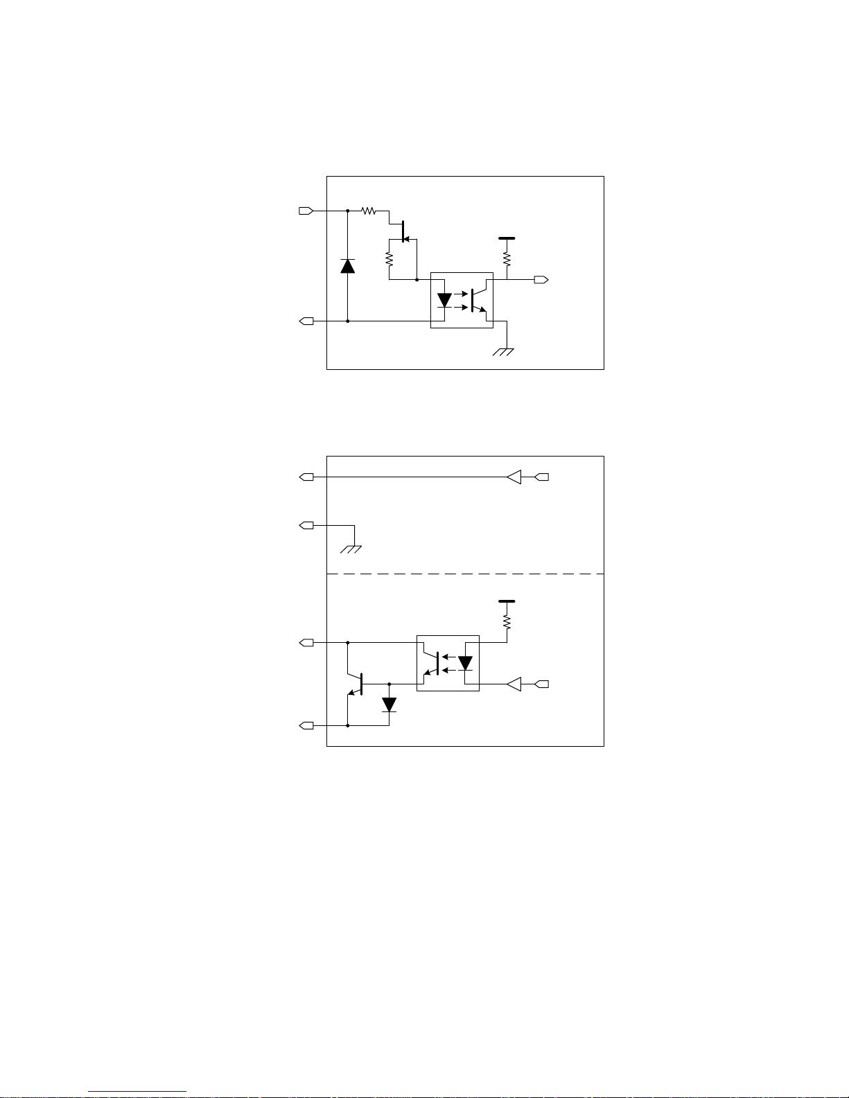
● Circuit diagram
- Trigger Input
TRIG_IN
Vcc
GND
TLP291
External Trigger Signal Input Circuit
LINE0
I/O_GND
(2pin)
(5pin)
- GPIO Output
Vcc
GND
TLP291
GPIO Signal Output Circuit
I/O_GND
(4pin)
GPIO1
LINE3
GPIO0LINE2
(5pin)
(3pin)
(6pin)
Fig.4-3 Circuit diagram
Page 25
24 / 80
Copyright © 2014 TOSHIBA TELI CORPORATION, All rights reserved. http://www.toshiba-teli.co.jp/index.htm
D4235067D
● I/O Timing
The received external trigger signal delays by internal circuit.
And LINE2 output delays from LINE1 output by the difference of internal circuit.
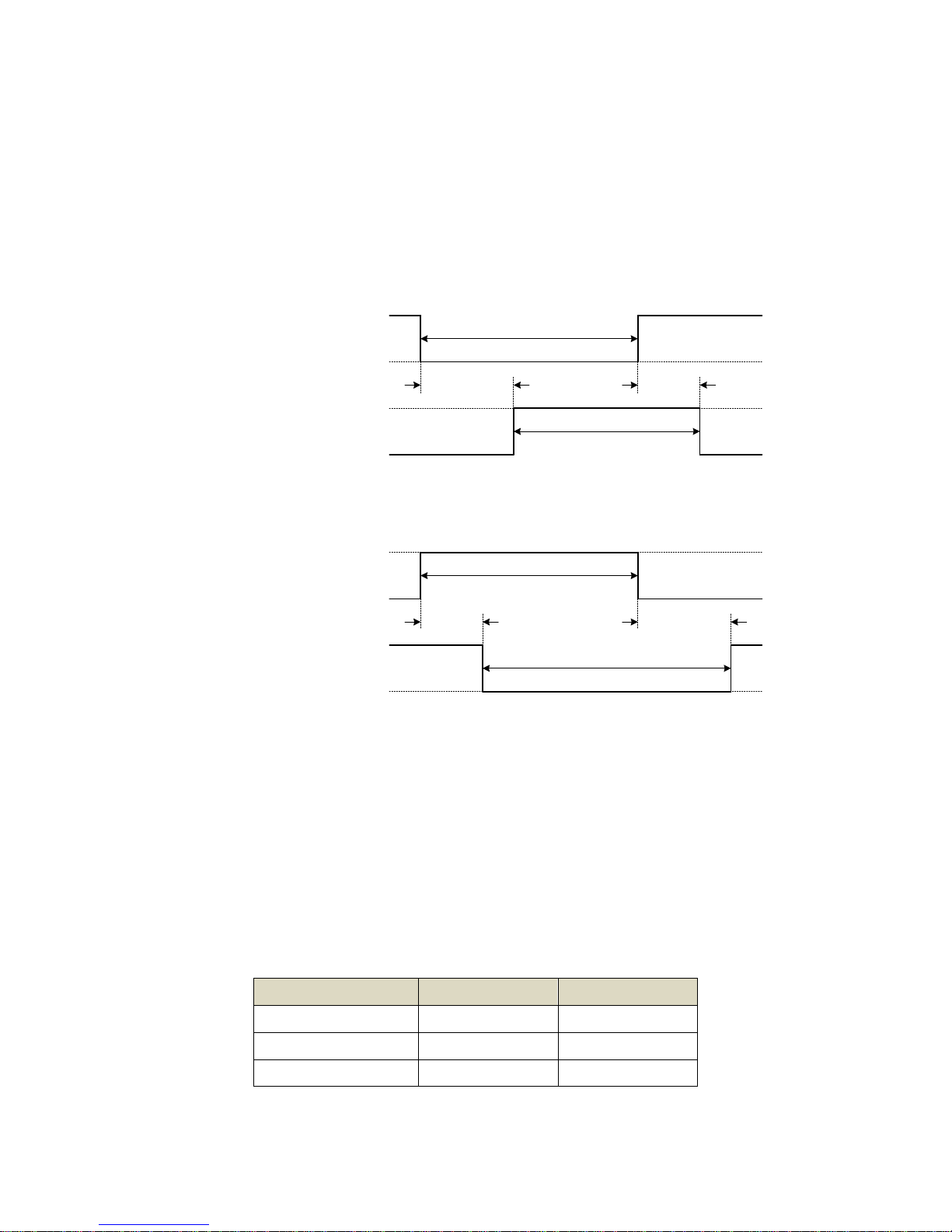
- Trigger Input
Ton
3.3 - 24V
EXT_TRIG
TRIG_IN
0V
0V
Vcc
EXT_TRIG_WIDTH
TRIG_IN_WIDTH
Toff
(internal signal)
(a) Negative
Ton
3.3 - 24V
EXT_TRIG
TRIG_IN
0V
0V
Vcc
EXT_TRIG_WIDTH
TRIG_IN_WIDTH
Toff
(internal signal)
(b) Positive
Fig.4-4 Trigger Signal Input Delay
EXT_TRIG_WIDTH: The pulse width of the external trigger input (more than 200μs).
Toff: The delay time of falling edge.
Ton: The delay time of rising edge.
TRIG_IN_WIDTH: The pulse width of the trigger signal which is received inside of the camera.
Negative trigger: TRIG_IN_WIDTH = EXT_TRIG_WIDTH - ( Ton - Toff )
Positive trigger: TRIG_IN_WIDTH = EXT_TRIG_WIDTH + ( Ton - Toff )
Table.4-2 Trigger input delay
Trigger amplitude
Toff [μs]
Ton [μs]
+3.3V
2.92
26.2
+12V
2.12
31.2
+24V
2.12
31.2
* Toff and Ton are typical value.
* These values are changed in operating environment.
Page 26

25 / 80
Copyright © 2014 TOSHIBA TELI CORPORATION, All rights reserved. http://www.toshiba-teli.co.jp/index.htm
D4235067D
- GPIO Output
Ton
OpenCollector
LINE1
LINE2
0V
0V
LVTTL
Toff
(OpenCollector)
(LVTTL)
(a) ActiveLow
Ton
LINE1
LINE2
0V
0V
LVTTL
Toff
(OpenCollector)
(LVTTL)
OpenCollector
(b) ActiveHigh
Fig.4-5 GPIO Signal Output Delay
Toff: LINE1~LINE2 falling delay time
Ton: LINE1~LINE2 rising delay time
Table.4-3 GPIO signals output delay
Pull-up amplitude
Toff [μs]
Ton [μs]
+3.3V
3
53.2
+12V
4
78.4
+24V
5
94.4
* Toff and Ton are typical value.
* These values are changed in operating environment.
Page 27

26 / 80
Copyright © 2014 TOSHIBA TELI CORPORATION, All rights reserved. http://www.toshiba-teli.co.jp/index.htm
D4235067D
● Anti-chattering process for Trigger input
In the characteristic of the open collector circuit, the signal is skewed. As a result, an unstable logic value
occurs. To filter out an unstable logic value, this camera has the anti-chattering circuit. Therefore, Random
Trigger Shutter operates only in the stable logic value.
Trig input circuit Logical circuit
I/O Connector
2pin: Line0
TGAnti Chattering
Camera inside
I/O
Ext Trig Trig in Act Trig
Trig in
(Logical)
Ext Trig
Trig in
Anti Chattering
Process
Act Trig
High threshold
Low threshold
Sampling step
Ton
3.3 - 24V
0V
0V
Vcc
Toff
Vcc / 2
High
Low
Sampling
Count
High
Low
Actual Trigger Width
External Trigger Width
Trigger in Width
Trig in
(logic)
Fig.4-6 Anti-chattering process
Page 28

27 / 80
Copyright © 2014 TOSHIBA TELI CORPORATION, All rights reserved. http://www.toshiba-teli.co.jp/index.htm
D4235067D
Timing Specification
Image data outputs of this camera series are transferred with the UDP protocol of Gigabit Ethernet. Timing
numerical value below is prescribed by absolute prerequisite that BG series use transmission band without
restriction of other node. When there is a node transferring with BG series concerned, it is not same the
numerical value prescribed below.
● Image Stream Output (normal shutter)
T2T1
GbE bus
Expose
ImageImage Image
T
DLY1
T
T2
DLY2
Fig.4-7 Image stream output
Table.4-4 Image stream output
Model
T1 [ms]
T2 [ms]
Default Framerate [ms]
BG205M-CS
see following
formula.
same as
Frame Rate.
20.0
BG205MC-CS
20.0
T
DLY1
: GVSP_BLOCK_START_DELAY
T
DLY2
: SCPD(Stream Channel Packet Delay)
* ,
B/W model: T1 = 100μs or longer, Color model: T1 = 250μs or longer
PayloadSize is total bytes of single frame.
The formula applies when SCPS (Stream Channel Packet Size) is 1500 byte / packet.
(T1 varies depending on the value of SCPS)
T1 = ( T2 / (
PayloadSize
SCPS - 36
) ) x 3
Page 29

28 / 80
Copyright © 2014 TOSHIBA TELI CORPORATION, All rights reserved. http://www.toshiba-teli.co.jp/index.htm
D4235067D
● Random Trigger Shutter Operation
TRIG_IN
0V
VCC
(internal signal)
Anti
Chattering
Exposure
T3
ExposureTime setting value
0V
VCC
T
DLY3
T
DLY4
Timed mode / FrameBurst(Bulk) mode (Image format: Mono8bit, all pixel readout)
TRIG_IN
0V
VCC
(internal signal)
Anti
Chattering
T
Exposure
T3 T4
0V
VCC
Pulse width of trigger signal
DLY3
T
DLY4
TriggerWidth mode (Image format: Mono8bit, all pixel readout)
Fig.4-8 Random Trigger Shutter operation
Table.4-5 Random Trigger Shutter operation
Model
T3 [μs]
T4 [μs]
BG205M-CS
0.26
0.26
BG205MC-CS
0.26
0.26
* TDLY3, TDLY4: TriggerSamplingPeriod (typical value)
Max TriggerSamplingPeriod x 1.625[μs], Min TriggerSamplingPeriod x 0.625[μs]
* T3 and T4 are typical value.
Page 30

29 / 80
Copyright © 2014 TOSHIBA TELI CORPORATION, All rights reserved. http://www.toshiba-teli.co.jp/index.htm
D4235067D
Notes of random trigger shutter mode:
- In the period when FRAME_TRIGGER_WAIT (GPIO signal) is inactive, user must not input external trigger signal to
this camera.
- When the interval of the input trigger signal is extremely short, or when the trigger signal is noisy, there is a possibility
of causing the malfunction. In this case, please input a proper trigger signal.
Page 31

30 / 80
Copyright © 2014 TOSHIBA TELI CORPORATION, All rights reserved. http://www.toshiba-teli.co.jp/index.htm
D4235067D
Typical Spectral Response
* The lens characteristics and light source characteristics is not reflected in table.
(a) BG205M-CS
Page 32

31 / 80
Copyright © 2014 TOSHIBA TELI CORPORATION, All rights reserved. http://www.toshiba-teli.co.jp/index.htm
D4235067D
(b) BG205MC-CS
(c) BG205MCF-CS
Fig.4-9 Spectral Response
Page 33

32 / 80
Copyright © 2014 TOSHIBA TELI CORPORATION, All rights reserved. http://www.toshiba-teli.co.jp/index.htm
D4235067D
Operating Ambient Conditions
● Ambient conditions
- Operating Assurance
Temperature: 0°C ~ 40°C, Camera housing temperature: less than 50°C
Humidity: 10% ~ 90% (no condensation)
- Storage Assurance
Temperature: -20°C ~ 60°C
Humidity: 90% or less (no condensation)
● EMC Conditions
- EMI (Electro-Magnetic Interference): EN61000-6-4
FCC Part 15 Subpart B Class A
- EMS (Electro-Magnetic Susceptibility): EN61000-6-2
Notes on Heat Radiation:
The temperature of camera housing must be kept less than 50 °C.
Please provide sufficient heat radiation depending on your installation.
Notes on Conformity of the EMC:
The adaptability of the safety standard of this camera is assured in the condition of combination with the following parts:
<< PoE operation>>
- PoE Switch GS108P-100AJS (NETGEAR Inc.)
- LAN Cable LD-TWST/BM30 (ELECOM CO., LTD)
<< DC operation>>
- DC Cable CPCBG-03
- LAN Cable LD-TWST/BM30 (ELECOM CO., LTD)
Please confirm the EMC adaptability when it combines with parts other than them.
Page 34

33 / 80
Copyright © 2014 TOSHIBA TELI CORPORATION, All rights reserved. http://www.toshiba-teli.co.jp/index.htm
D4235067D
5. Functions
This section introduces standard functions of BG series. This camera series provides following functions.
Table.5-1 List of Functions
Category
Function
DeviceControl
DeviceControl
Get device information
ImageFormatControl
Scalable
Set scalable operation
Decimation
Set decimation operation
Reverse
Set image flipping operation
PixelFormat
Select pixel format
TestImageSelector
Select test pattern
AcquisitionControl
AcquisitionControl
Execute stream start / stop
TriggerControl
Control trigger operation
ExposureControl
Control exposure
DigitalIOControl
DigitalIOControl
Control GPIO signals
CounterAndTimerControl
TimerControl
Control Timer0Active signal
EventControl
EventControl
Control event packet
AnalogControl
Gain
Set gain
BalanceRatio
Set color gain (R, B gain)
BalanceWhiteAuto
Execute auto white balance once
BlackLevel
Set black level
Gamma
Set gamma correction
BlackLevelCorrection
Set black level correction
LUTControl
LUTControl
Control LUT
TransportLayerControl
TransportLayerControl
Control transport layer
UserSetControl
UserSetControl
Load / Save user setting
ALCControl
ALCControl
Control ALC operation
Page 35

34 / 80
Copyright © 2014 TOSHIBA TELI CORPORATION, All rights reserved. http://www.toshiba-teli.co.jp/index.htm
D4235067D
Function
BG205M
BG205MC
DeviceControl
○
○
Scalable
○
○
Decimation
○
○
Reverse
○
○
PixelFormat
○
○
TestImageSelector
○
○
AcquisitionControl
○
○
TriggerControl
○
○
ExposureControl
○
○
DigitalIOControl
○
○
TimerControl
○
○
EventControl
○
○
Gain
○
○
BalanceRatio
-
○
BalanceWhiteAuto
-
○
BlackLevel
○
○
Gamma
○
○
BlackLevelCorrection
○
○
LUTControl
○
○
TransportLayerControl
○
○
UserSetControl
○
○
ALCControl
○
○
Page 36

35 / 80
Copyright © 2014 TOSHIBA TELI CORPORATION, All rights reserved. http://www.toshiba-teli.co.jp/index.htm
D4235067D
DeviceControl
Registers of this category provide various information of the camera. And you can set the free user ID to the
camera.
● Registers
Register
Visibility
Access
Description
DeviceScanType
Expert
R
Returns the scan type.
DeviceVendorName
Beginner
R
Returns the vendor name.
DeviceModelName
Beginner
R
Returns the model name.
DeviceManufacturerInfo
Beginner
R
Returns the manufacturer information.
DeviceVersion
Beginner
R
Returns the device version.
DeviceFirmwareVersion
Beginner
R
Returns the firmware version.
DeviceSFNCVersionMajor
Beginner
R
Returns the SFNC version of GenICam XML.
DeviceSFNCVersionMinor
Beginner
R
DeviceSFNCVersionSubMinor
Beginner
R
DeviceID
Beginner
R
Returns the Device ID (serial number).
DeviceUserID
Beginner
R/W
Set the free user ID.
DeviceRegistersStreamingStart
Guru
W
Executes inactivating the validation of consistency.
DeviceRegistersStreamingEnd
Guru
W
Executes activating the validation of the consistency.
DeviceRegistersCheck
Expert
W
Executes the validation of the current register set for consistency.
DeviceRegistersValid
Expert
R
Returns the result that executed “DeviceRegistersCheck”.
TRUE: Consistency, FALSE: Inconsistency
Page 37

36 / 80
Copyright © 2014 TOSHIBA TELI CORPORATION, All rights reserved. http://www.toshiba-teli.co.jp/index.htm
D4235067D
Scalable
BG series provide the scalable mode that can read out defined area of the screen.
In the scalable mode, camera reads out only necessary area at the normal speed and reads out other area
at high speed. The frame rate can be faster when the vertical height size is small. However, the frame rate
cannot be faster only when the horizontal width size is small.
Only single rectangle is selectable. Concave or convex shape is not selectable.
- Window size: {A + 4 × m (H)} × {B + 2 × n (V)}
A, B = minimum unit size
m, n = integer
The window size is equal or less than maximum image size.
- Start address: {4 x i (H)} x {2 x j (V)}
i, j = integer
The window size is equal or less than maximum image size.
⇒
( X, Y ) = ( 4 x i, 2 x j )
B + 2 x n
A + 4 x m
Fig.5-1 Scalable
● Registers
Register
Visibility
Access
Description
SensorWidth
Beginner
R
Returns effective width of the sensor in pixels.
SensorHeight
Beginner
R
Returns effective Height of the sensor in pixels.
WidthMax
Expert
R
Returns maximum width (in pixels) of the image.
HeightMax
Expert
R
Returns maximum Height (in pixels) of the image.
Width
Beginner
R/W
Sets width (in pixels) of the image data.
Height
Beginner
R/W
Sets Height (in pixels) of the image data.
OffsetX
Beginner
R/W
Sets horizontal offset (in pixels) from the origin to the region of interest.
OffsetY
Beginner
R/W
Sets vertical offset (in pixels) from the origin to the region of interest.
Page 38

37 / 80
Copyright © 2014 TOSHIBA TELI CORPORATION, All rights reserved. http://www.toshiba-teli.co.jp/index.htm
D4235067D
● Setting
- Set image size and image start position
Set the following value to “Width”, “Height”, “OffsetX”, “OffsetY” registers. Setting value is Integer type.
“Width”, “Height” registers are image size setting. “OffsetX”, “OffsetY” registers are image start position
setting.
Model
BG205M
BG205MC
Width unit size
4 4 Height unit size
2 2 OffsetX unit size
4 4 OffsetY unit size
2 2 Minimum unit size
64×64
64×64
Maximum unit size (*)
2048×1088
2048×1088
* initial factory setting
● Note
Changing “Width”, “Height”, “OffsetX”, “OffsetY” register value is invalid during image stream data output.
Page 39

38 / 80
Copyright © 2014 TOSHIBA TELI CORPORATION, All rights reserved. http://www.toshiba-teli.co.jp/index.htm
D4235067D
Decimation
In the Decimation mode, camera outputs the image that thinned out the line(s). By thinning out the line(s) of
the image, camera outputs all effective areas at high speed and decreases GigE bandwidth occupation.
2 lines vertical decimation
1088
2048
544
all pixel readout
272
8 lines vertical decimation
136
4 lines vertical decimation
Fig.5-2 Decimation operation
● Registers
Register
Visibility
Access
Description
DecimationVertical
Beginner
R/W
Set the number of vertical Decimation line(s).
Page 40

39 / 80
Copyright © 2014 TOSHIBA TELI CORPORATION, All rights reserved. http://www.toshiba-teli.co.jp/index.htm
D4235067D
● Setting
- Set Decimation lines
Set the following value to "DecimationVertical" registers. Setting value is Integer type.
"DecimationVertical" is the number of line(s) to skip.
Model
BG205M
BG205MC
Minimum (*)
1 1 Value
1, 2, 4, 8
1, 2, 4, 8
Maximum
8
8
* initial factory setting
● Note
Decimation function is disabled when the camera is running in Scalable mode.
Scalable function is disabled when the camera is running in Decimation mode.
Changing "DecimationVertical" register value is invalid during image stream data output.
Page 41

40 / 80
Copyright © 2014 TOSHIBA TELI CORPORATION, All rights reserved. http://www.toshiba-teli.co.jp/index.htm
D4235067D
Reverse
Image can be flipped in horizontal and/or vertical direction.
ReverseX
ReverseY ReverseX+ReverseY
Fig.5-3 Image Flipping
● Registers
Register
Visibility
Access
Description
ReverseX
Expert
R/W
Flip image in horizontal direction.
ReverseY
Expert
R/W
Flip image in vertical direction.
● Setting
- Set image reverse
Set the following value to "ReverseX", "ReverseY" registers. Setting value is Boolean type.
Value
Image reverse
FALSE (*)
Non reverse
TRUE
Reverse
* initial factory setting
● Note
Page 42

41 / 80
Copyright © 2014 TOSHIBA TELI CORPORATION, All rights reserved. http://www.toshiba-teli.co.jp/index.htm
D4235067D
PixelFormat
Select a pixel format of image stream data. This camera provides Mono8 bit or Bayer 8bit Pixel format.
● Registers
Register
Visibility
Access
Description
PixelFormat
Beginner
R/W
Selects a pixel format.
PixelSize
Expert
R
Returns a bit size of image pixel.
● Setting
- Selects a pixel format
Set a following value to “PixelFormat” register. Setting value is Enumeration type.
B/W model
ReverseX
ReverseY
Value
PixelFormat
PixelSize
False (*)
False (*)
Mono8
Mono 8 bit packed
Bpp8: 8 bits per pixel
True
False
False
True
True
True
* initial factory setting
Color model
ReverseX
ReverseY
Value
PixelFormat
PixelSize
False (*)
False (*)
BayerGR8
Bayer Green Red 8 bit
Bpp8: 8 bits per pixel
True
False
BayerRG8
Bayer Red Green 8 bit
False
True
BayerBG8
Bayer Blue Green 8 bit
True
True
BayerGB8
Bayer Green Blue 8 bit
* initial factory setting
● Note
Changing “PixelFormat” register value is invalid during image stream data output.
Page 43

42 / 80
Copyright © 2014 TOSHIBA TELI CORPORATION, All rights reserved. http://www.toshiba-teli.co.jp/index.htm
D4235067D
TestImageSelector
BG series support test pattern data output. Camera provides following Test patterns;
Black White
BrightGrey DarkGrey
GreyHorizontalRamp
Fig.5-4 Test pattern
Page 44

43 / 80
Copyright © 2014 TOSHIBA TELI CORPORATION, All rights reserved. http://www.toshiba-teli.co.jp/index.htm
D4235067D
● Registers
Register
Visibility
Access
Description
TestImageSelector
Beginner
R/W
Selects a test pattern.
● Setting
- Select a test pattern output
Set the following value to “TestImageSelector” register. Setting value is Enumeration type.
The camera generates a test pattern.
Value
Function
Off (*)
Test pattern disable(Normal data output)
Black
All pixel = 0 LSB
White
All pixel = 255 @Mono8
BrightGrey
All pixel = 170 @Mono8
DarkGrey
All pixel = 85 @Mono8
GreyHorizontalRamp
Horizontal Ramp
* initial factory setting
● Note
Page 45

44 / 80
Copyright © 2014 TOSHIBA TELI CORPORATION, All rights reserved. http://www.toshiba-teli.co.jp/index.htm
D4235067D
AcquisitionControl
Make a setting of image stream and control image stream output.
Camera starts image stream output by receiving AcquisitionStrat command. And there are some registers
that require camera to stop image stream output to change values.
Acquisition frame rate is variable. Maximum acquisition frame rate depends on camera operation mode
(scalable, binning, decimation, link speed, etc.)
● Registers
Register
Visibility
Access
Description
AcquisitionMode
Beginner
R
Returns acquisition mode.
AcquisitionStart
Beginner
W
Executes the image stream output start.
AcquisitionStop
Beginner
W
Executes the image stream output stop.
AcquisitionAbort
Beginner
W
Executes the image stream output abort.
AcquisitionFrameBurstCount
Beginner
R/W
Sets number of Exposures to acquire for each FrameBurstStart trigger.
AcquisitionFrameRate
Beginner
R/W
Sets frame rate of image stream.
● Setting
- Start image stream output
The camera starts image stream output by executing “AcquisitionStart” register command.
- Stop image stream output
The camera stops image stream output by executing “AcquisitionStop” register command.
The camera aborts image stream output by executing “AcquisitionAbort” register command.
- Sets number of Exposures for FrameBurstStart trigger
Set the following value to “AcquisitionFrameBurstCount” register. Setting value is Integer type.
FrameBurstCount
Value
Minimum (*)
1 [time]
Maximum
255 [times]
* initial factory setting
Page 46

45 / 80
Copyright © 2014 TOSHIBA TELI CORPORATION, All rights reserved. http://www.toshiba-teli.co.jp/index.htm
D4235067D
- Sets frame rate
Set the following value to “AcquisitionFrameRate” register. Setting value is Float type.
The range of register setting depends on camera model, and camera operation mode.
FrameRate
Value
Minimum
0.0625[Hz]
Maximum (*)
Depend on register setting of "Height", "Binning", "Decimation", "PacketSize" and "PixelFormat" or link
speed of interface.
* initial factory setting
● Note
Changing “AcquisitionFrameRate” register value is invalid during image stream data output.
When exposure time setting is longer than frame rate setting, camera operation gives priority to exposure
time setting.
Notes on Frame Drops of Image:
Depends on your PC or Gigabit Ethernet interface board configurations, images may not be captured normally (e.g.
frame drops may occur). In this case, change to frame rate setting lower.
Page 47

46 / 80
Copyright © 2014 TOSHIBA TELI CORPORATION, All rights reserved. http://www.toshiba-teli.co.jp/index.htm
D4235067D
TriggerControl
This section describes trigger control of AcquisitionControl category for the BG series.
This camera series provides two kinds of exposure synchronization.
1. Normal Shutter mode : Free run operation (internal synchronization)
2. Random Trigger Shutter mode : Synchronized with external trigger input
In Random Trigger Shutter mode, two kinds of trigger input are available.
1. Trigger signal via the I/O connector (HardwareTrigger)
2. Trigger command via the Gigabit Ethernet interface (SoftwareTrigger)
The following table shows the combination of operation mode of this camera series.
Table.5-2 Operation Mode
Trigger Mode
(TriggerMode)
Synchronization
(TriggerSource)
Exposure Control
(ExposureAuto / ExposureMode)
Trigger Type
(TriggerSelector)
Normal Shutter mode
(Off)
Free run
(Don’t Care)
“ExposureTime” register control
(Off / Timed)
Free run
(Don’t Care)
ALC control
(On / Timed)
Random Trigger Shutter mode
(On)
HardwareTrigger
(Line0)
“ExposureTime” register control
(Off / Timed)
Normal Trigger mode
(FrameStart)
FrameBurst mode
(FrameBurstStart)
Trigger pulse width control
(Off / TriggerWidth)
Normal Trigger mode
(FrameStart)
SoftwareTrigger
(Software)
“ExposureTime” register control
(Off / Timed)
Normal Trigger mode
(FrameStart)
FrameBurst mode
(FrameBurstStart)
* The camera operation not mentioned above is not guaranteed.
- Trigger Porarity
Operation point of HardwareTrigger is at the edge of trigger signal, and active edge polarity is able to
change by register setting.
Page 48

47 / 80
Copyright © 2014 TOSHIBA TELI CORPORATION, All rights reserved. http://www.toshiba-teli.co.jp/index.htm
D4235067D
- Trigger Delay
And you can add delay time from trigger edge to exposure start by register setting.
GbE bus
Exposure
Trigger signal
Image
TriggerDelay
Fig.5-5 Trigger Delay
- Trigger Type
1. FrameStart: Camera exposes and transfers a single frame by a single trigger.
Trigger
Image
GbE bus
Exposure
ExposureTime
Image Image
2. FrameBurstStart: Camera exposes and transfers multiple frames by a single trigger.
GbE bus
Exposure
ExposureTime
Image Image Image
AcquisitionBurstFrameCount = 4
Image
FrameRate
Trigger
Fig.5-6 Trigger Type
Page 49

48 / 80
Copyright © 2014 TOSHIBA TELI CORPORATION, All rights reserved. http://www.toshiba-teli.co.jp/index.htm
D4235067D
- Anti-Chattering
Anti-Chattering control filters noise and unstable logic value of the trigger input signal.
Anti
Chattering
Sampling period
VCC
0V
VCC
0V
Actual Trigger Width
TRIG_IN
(logical)
L L H H L
Fig.5-7 Anti-Chattering
Details of Random Trigger Shutter operation, refer to "Timing" of "Specification".
● Registers
Register
Visibility
Access
Description
TriggerSelector
Beginner
R/W
Selects the type of trigger.
TriggerMode
Beginner
R/W
Selects Random Trigger Shutter mode.
TriggerSoftware
Beginner
W
Executes software trigger.
TriggerSource
Beginner
R/W
Selects trigger source of Random Trigger Shutter.
TriggerActivation
Beginner
R/W
Selects trigger polarity of hardware trigger.
TriggerDelay
Expert
R/W
Sets trigger delay.
TriggerSamplingPeriod
Expert
R/W
Sets sampling period for Anti-Chattering.
Page 50

49 / 80
Copyright © 2014 TOSHIBA TELI CORPORATION, All rights reserved. http://www.toshiba-teli.co.jp/index.htm
D4235067D
● Setting
- Selects trigger type
Set the following value to “TriggerSelector” register. Setting value is Enumeration type.
Value
Operation Mode
FrameStart(*)
Normal Trigger mode
FrameBurstStart
FrameBurst mode
* initial factory setting
- Selects trigger mode
Set the following value to “TriggerMode” register. Setting value is Enumeration type.
Value
Operation Mode
Off (*)
Normal Shutter Mode
On
Random Trigger Shutter mode
* initial factory setting
- Selects trigger source
Set the following value to “TriggerSource” register. Setting value is Enumeration type.
Value
Trigger source
Line0 (*)
Hardware trigger
Software
Software trigger
* initial factory setting
- Grabs image stream by software trigger
When executes “TriggerSoftware” register command, software trigger command is generated. And the
camera starts exposure by receiving software trigger command in software trigger mode.
Page 51

50 / 80
Copyright © 2014 TOSHIBA TELI CORPORATION, All rights reserved. http://www.toshiba-teli.co.jp/index.htm
D4235067D
- Changes trigger polarity (HardwareTrigger operation only)
Set the following value to “TriggerActivation” register. Setting value is Enumeration type.
Value
Polarity
FallingEdge (*)
Negative
RisingEdge
Positive
* initial factory setting
- Sets trigger delay (HardwareTrigger operation only)
Set the following value to “TriggerDelay” register. Setting value is Float type.
Adds delay time from trigger edge to exposure start.
TriggerDelay
Value
Minimum (*)
0.00[μs]
Maximum
4095.00[μs]
* initial factory setting
- Sets sampling period for Anti-Chattering (HardwareTrigger operation only)
Set the following value to “TriggerSamplingPeriod” register. Setting value is Float type.
TriggerSamplingPeriod[μs]
Value
Minimum (*)
2.00[μs]
Maximum
1000.00[μs]
* initial factory setting
● Note
Changing “TriggerMode”, “TriggerSource”, “TriggerActivation” registers value is invalid during image stream
data output.
In SoftwareTrigger operation, it takes less than 1ms from “TriggerSoftware” command to exposure start.
When set longer value to “TriggerSamplingPeriod” register, noise immunity of trigger input line is improved,
but the delay time of receiving trigger signal become longer.
Page 52

51 / 80
Copyright © 2014 TOSHIBA TELI CORPORATION, All rights reserved. http://www.toshiba-teli.co.jp/index.htm
D4235067D
ExposureControl
BG series is able to adjust exposure time by using electric shutter control.
This camera series provides two kinds of exposure time control mode.
- MANUAL mode : The exposure time is determined by “ExposureTime” register setting value.
- AE mode : The exposure time is adjusted automatically by the photometry of the image.
By combining AE mode and AGC (ALC mode), it can adjust a wide range of brightness fluctuation of the
subject. About details of ALC mode, refer to "ALC Control" of "Functions".
When HardwareTrigger operation, you are able to control the exposure time by pulse width of external
trigger input signal.
Image
GbE bus
Exposure
Trigger
ExposureTime
GbE bus
Exposure
Trigger
Pulse Width
Image
Timed mode TriggerWidth mode
Fig.5-8 Exposure control
● Registers
Register
Visibility
Access
Description
ExposureMode
Beginner
R/W
Selects manual exposure mode.
ExposureTime
Beginner
R/W
Sets absolute exposure time(timed mode).
ExposureAuto
Beginner
R/W
Sets AE operation.
Page 53

52 / 80
Copyright © 2014 TOSHIBA TELI CORPORATION, All rights reserved. http://www.toshiba-teli.co.jp/index.htm
D4235067D
● Setting
- Selects exposure control mode
Set the following value to “ExposureMode” register. Setting value is Enumeration type.
Value
Manual exposure mode
Timed (*)
“ExposureTime” register control
TriggerWidth
Trigger pulse width control
* initial factory setting
In Normal Shutter mode, the exposure time is determined by “ExposureTime” register value regardless of
“ExposureMode” register setting.
- Sets exposure time (timed mode only)
Set the following value to “ExposureTime” register. Setting value is Float type.
Set the exposure time of Normal Shutter mode, and Random Trigger Shutter -Timed mode operation.
Model
BG205M / BG205MC
ExposureTime (*)
20000 [μs]
ExposureTimeMin
10 [μs]
ExposureTimeMax
1000000 [μs]
* initial factory setting
- Set auto exposure
Set the following value to “ExposureAuto” register. Setting value is Enumeration type.
Select the exposure control.
Value
Function
Off (*)
Manual Exposure control
On
Auto Exposure control
* initial factory setting
● Note
Changing “ExposureMode” register value is invalid during image stream data output.
Page 54

53 / 80
Copyright © 2014 TOSHIBA TELI CORPORATION, All rights reserved. http://www.toshiba-teli.co.jp/index.htm
D4235067D
DigitalIOControl
This section describes DigitalIOControl category for the BG series.
This camera provides GPIO output selected by the register setting. And the polarity of the signal is able to
switch by the register setting. The following chart shows the specifications of the selectable signals.
EXT_TRIG
Exposure
VD
Image Transfer
GigE Bus
TIMER0 ACTIVE
EXPOSURE
ACTIVE
FRAME ACTIVE
FRAME
TRANSFER
FRAME TRIGGER
WAIT
Delay Duration
* ActiveLow
Fig.5-9 Selectable signals
● Registers
Register
Visibility
Access
Description
LineSelector
Expert
R/W
Selects the Line of I/O connector.
LineMode
Expert
R
Returns the direction of each Line signal.
LineInverter
Expert
R/W
Selects the polarity of GPIO output signal.
LineSource
Expert
R/W
Selects the source of the output signal.
LineFormat
Expert
R
Returns the type of each Line signal.
Page 55

54 / 80
Copyright © 2014 TOSHIBA TELI CORPORATION, All rights reserved. http://www.toshiba-teli.co.jp/index.htm
D4235067D
● Setting
- Select the Line of the I/O connector
Set the following value to “LineSelector” register. The setting value is Enumeration type.
LineSelector
I/O connector pin assignment
LineMode
LineFormat
Line0 (*)
2 pin: External Trigger Input
Input
OptoCoupled: OpenCollector
Line1
3 pin: GPIO0 Output
Output
TTL: LVTTL
Line2
4 pin: GPIO1 Output
Output
OptoCoupled: OpenCollector
* initial factory setting
- Select the polarity of GPIO output signal
Set the following value to “LineInverter” register. The setting value is Boolean type.
Value
Polarity
FALSE (*)
ActiveLow
TRUE
ActiveHigh
* initial factory setting
- Select the source of GPIO output signal
Set the following value to “LineSource” register. Setting value is Enumeration type.
Value
Signal description
Off (*)
No output.
FrameTriggerWait
Indicating waiting a Random Trigger Shutter.
An External trigger is input during this period, exposure starts immediately.
FrameTransfer
Period of transferring image data on Ethernet bus.
FrameActive
Period from exposure start to image transfer completion.
ExposureActive
Period from exposure start to exposure end.
Timer0Active
This signal can be used as strobe control signal.
The delay time and pulse width of this signal are configurable.
VD
Internal VD sync signal.
* initial factory setting
● Note
About the details of Timer0Active signal, refer to “TimerControl” of "Functions".
Page 56

55 / 80
Copyright © 2014 TOSHIBA TELI CORPORATION, All rights reserved. http://www.toshiba-teli.co.jp/index.htm
D4235067D
TimerControl
This section describes TimerControl category for the BG series.
This camera series is able to generate Timer0Active signal, derived from exposure start, by register setting.
This signal can be used as strobe control signal.
EXT_TRIG
Exposure
TIMER0 ACTIVE
Delay Duration
* ActiveLow
EXPOSURE ACTIVE
Fig.5-10 Timer0Active
● Registers
Register
Visibility
Access
Description
TimerSelector
Expert
R
Returns the name of the timer that selected.
TimerDuration
Expert
R/W
Sets the width of Timer0Active signal.
TimerDelay
Expert
R/W
Sets the delay of Timer0Active signal.
TimerTriggerSource
Expert
R
Returns the timing that is the basic of the timer
● Setting
- Set the width of Timer0Active pulse
Set the following value to “TimerDuration” register. Setting value is Float type.
Pulse width
Value
Minimun (*)
0.00[μs]
Maximum
2000000.00[μs]
* initial factory setting
Page 57

56 / 80
Copyright © 2014 TOSHIBA TELI CORPORATION, All rights reserved. http://www.toshiba-teli.co.jp/index.htm
D4235067D
- Set the delay of Timer0Active pulse
Set the following value to “TimerDelay” register. Setting value is Float type.
Delay
Value
Minimun (*)
0.00[μs]
Maximum
2000000.00[μs]
* initial factory setting
● Note
Page 58

57 / 80
Copyright © 2014 TOSHIBA TELI CORPORATION, All rights reserved. http://www.toshiba-teli.co.jp/index.htm
D4235067D
EventControl
This section describes EventControl category for the BG series.
This camera series provides Event notifications of ALC and trigger operation information.
The detail of Event notifications is following;
- FrameTrigger : Reception of Frame Start Trigger
- FrameTriggerError : Rejection of Frame Start Trigger
- FrameTriggerWait : Start of waiting for Frame Start Trigger
- ALCLastestInformation : ALC Information is updated
- ALCConverged : ALC is converged
FrameTrigger events timing are as following chart.
A B C D E
A B C
Overlap Trigger Reception
A B C
(1) (1) (1)
FrameTriggerWait
EXT_TRIG
Exposure
Image Transfer
GbE Bus
(3) (3) (3)
FrameTriggerWait will be activated before
approx. (Sensor Read Out End - Exposure Time)
D E
D E
(1)
(3)
(2) (1)
This trigger is
ignored.
(3) FrameTriggerWait
(1) FrameTrigger
(2) FrameTriggerError
: Reception of Frame Start Trigger.
: Rejection of Frame Start Trigger.
: Start of waiting for Frame Start Trigger.
Overlap Trigger Rejection
Fig.5-11 FrameTrigger / Error / Wait Event timing
Page 59

58 / 80
Copyright © 2014 TOSHIBA TELI CORPORATION, All rights reserved. http://www.toshiba-teli.co.jp/index.htm
D4235067D
● Registers
Register
Visibility
Access
Description
EventControl
EventSelector
Expert
R/W
Selects the type of Event notifications.
EventNotification
Expert
R/W
Sets the activation of Event notifications.
EventFrameTriggerData
EventFrameTrigger
Expert
R
Returns Event ID of FrameTrigger type.
EventFrameTriggerTimestamp
Expert
R
Returns the timestamp at the time of Event.
EventFrameTriggerErrorData
EventFrameTriggerError
Expert
R
Returns Event ID of FrameTriggerError type.
EventFrameTriggerErrorTimestamp
Expert
R
Returns the timestamp at the time of Event.
EventFrameTriggerWaitData
EventFrameTriggerWait
Expert
R
Returns Event ID of FrameTriggerWait type.
EventFrameTriggerWaitTimestamp
Expert
R
Returns the timestamp at the time of Event.
EventALCLatestInformationData
EventALCLatestInformation
Expert
R
Returns Event ID of ALCLatestInformation type.
EventALCLatestInformationTimestamp
Expert
R
Returns the timestamp at the time of Event.
EventALCLatestInformationTotalLuminance
Expert
R
Returns the total luminance at the time of Event.
EventALCLatestInformationAverageLuminance
Expert
R
Returns the average luminance at the time of Event.
EventALCLatestInformationExposureTime
Expert
R
Returns the exposure time at the time of Event.
EventALCLatestInformationGain
Expert
R
Returns the gain at the time of Event.
EventALCConvergedData
EventALCConverged
Expert
R
Returns Event ID of ALCConverged type.
EventALCConvergedTimestamp
Expert
R
Returns the timestamp at the time of Event.
EventALCConvergedLuminanceTotal
Expert
R
Returns the total luminance at the time of Event.
EventALCConvergedLuminanceAverage
Expert
R
Returns the average luminance at the time of Event.
EventALCConvergedExposureTime
Expert
R
Returns the exposure time at the time of Event.
EventALCConvergedGain
Expert
R
Returns the gain at the time of Event.
Page 60

59 / 80
Copyright © 2014 TOSHIBA TELI CORPORATION, All rights reserved. http://www.toshiba-teli.co.jp/index.htm
D4235067D
● Setting
- Select the type of Event notifications
Set the following value to “EventSelector” register. The setting value is Enumeration type.
Value
Type of Event notification
FrameTrigger (*)
Information of trigger operation
FrameTriggerError
Error information of trigger operation
FrameTriggerWait
Information of wait for trigger input
ALCLatestInformation
Information of ALC update
ALCConverged
Information of ALC convergence
* initial factory setting
- Set the activation of Event notifications
Set the following value to “EventNotification” register. The setting value is Enumeration type.
Value
Event notification
Off (*)
Inactive
On
Active
* initial factory setting
● Note
This camera takes about 4 ms to event notification.
Page 61

60 / 80
Copyright © 2014 TOSHIBA TELI CORPORATION, All rights reserved. http://www.toshiba-teli.co.jp/index.htm
D4235067D
Gain
This section describes Gain control of AnalogControl category for the BG series.
This control adjusts the gain of the image.
Gain
output
signal
input signal
Fig.5-12 Gain
This camera series provides two kinds of Gain control mode.
- ManualControl (MANUAL) : The Gain value is determined by “Gain” register setting value.
- AutoGainControl (AGC) : The Gain value is adjusted automatically by the photometry of the image.
● Registers
Register
Visibility
Access
Description
GainSelector
Beginner
R
Returns the luminance component of Gain setting.
Gain
Beginner
R/W
Sets the absolute Gain.
GainAuto
Beginner
R/W
Sets activation of AGC mode.
Page 62

61 / 80
Copyright © 2014 TOSHIBA TELI CORPORATION, All rights reserved. http://www.toshiba-teli.co.jp/index.htm
D4235067D
● Setting
- Set Manual Gain
Set the following value to “Gain” register. Setting value is Float type. This setting value is valid only at
Manual Gain mode setting.
Gain
Value
Minimum (*)
0.00 [dB]
Maximum
18.00 [dB]
* initial factory setting
The formula of Gain value is as follows;
output signal = input signal x 10
Gain
20
- Select Gain control mode
Set the following value to “GainAuto” register. Setting value is Enumeration type.
Value
Mode
Off (*)
Manual Gain Control (MANUAL)
Continuous
Auto Gain Control (AGC)
* initial factory setting
● Note
About the details of AGC mode, refer to “ALCControl” of "Functions".
Notes on gain setting:
Setting the gain value too high increases noises. When you adjust the brightness of the image, I ask you to have final
image quality checked with your environment.
Page 63

62 / 80
Copyright © 2014 TOSHIBA TELI CORPORATION, All rights reserved. http://www.toshiba-teli.co.jp/index.htm
D4235067D
BalanceRatio
This section describes BalanceRatio control of AnalogControl category for the BG series.
This control adjusts the white balance gain of the image.
This function is available only in Color models.
R G B R G B
BalanceRatioRBalanceRatio
B
Input Signal Level Output Signal Level
Fig.5-13 BalanceRatio
● Registers
Register
Visibility
Access
Description
BalanceRatioSelector
Expert
R/W
Selects a color component of white balance gain to control.
BalanceRatio
Expert
R/W
Sets a white balance gain.
● Setting
- Select BalanceRatio
Select the color component of white balance gain to control in “BalanceRatioSelector” register.
Setting value is Enumeration type.
Value
Function
R (*)
BalanceRatio = R Gain
B
BalanceRatio = B Gain
* initial factory setting
Page 64

63 / 80
Copyright © 2014 TOSHIBA TELI CORPORATION, All rights reserved. http://www.toshiba-teli.co.jp/index.htm
D4235067D
- Set BalanceRatio
Set the following value to “BalanceRatio” register. The value is to be applied to selected color
component. Setting value is Float type.
BalanceRatio
Value
Minimum
x 0.5
Maximum
x 8.0
* initial factory setting = x 1.0
Notes on white balance gain setting:
Too high white balance gain increases noises. After adjusting the white balance of the image, I ask you to have final
image quality checked with your environment.
Page 65

64 / 80
Copyright © 2014 TOSHIBA TELI CORPORATION, All rights reserved. http://www.toshiba-teli.co.jp/index.htm
D4235067D
BalanceWhiteAuto
Adjust white balance gain automatically.
This function is available only in Color models.
● Registers
Register
Visibility
Access
Description
BalanceWhiteAuto
Expert
R/W
Adjust white balance gain automatically.
● Setting
- Set BalanceWhiteAuto
Set the following value to “BalanceWhiteAuto” register.
After setting “Once”, camera executes auto white balance once. If execution of auto white balance is
successful, both R and B gain are applied to BalanceRatio respectively.
Value
Function
Off (*)
No operation
Once
Execute auto white balance once.
* initial factory setting
● Note
BalanceRatio and BalanceWhiteAuto controls are available in following PixelForamt modes.
Bayer*8
Page 66

65 / 80
Copyright © 2014 TOSHIBA TELI CORPORATION, All rights reserved. http://www.toshiba-teli.co.jp/index.htm
D4235067D
BlackLevel
This section describes BlackLevel control of AnalogControl category for the BG series.
This control adjusts the black level of the image. It is adjustable from -5% to +25% as white saturation level
is 100%. However, when BlackLevel is lower than 0[%], the image level may not be saturated.
Image Signal
saturation level
0
Black
Level
255(@8bit)
Fig.5-14 Black Level
● Registers
Register
Visibility
Access
Description
BlackLevelSelector
Beginner
R
Returns the luminance component of Black Level setting.
BlackLevel
Beginner
R/W
Sets the absolute Black Level.
● Setting
- Set Black Level
Set the following value to “BlackLevel” register. Setting value is Float type.
BlackLevel
Value
Minimum
-5.00[%]
Maximum
+25.00[%]
* initial factory setting = 0.00[%]
● Note
Page 67

66 / 80
Copyright © 2014 TOSHIBA TELI CORPORATION, All rights reserved. http://www.toshiba-teli.co.jp/index.htm
D4235067D
Gamma
This section describes Gamma correction of AnalogControl category for the BG series.
This function allows you to apply a gamma correction to the output images.
input
luminance
output
luminance
Gamma
Fig.5-15 Gamma correction
● Registers
Register
Visibility
Access
Description
Gamma
Beginner
R/W
Sets the Gamma correction.
● Setting
- Set Gamma correction
Set the following value to “Gamma” register. Setting value is Float type.
Gamma
Value
Minimum
0.45
Maximum (*)
1.00
* initial factory setting
● Note
Page 68

67 / 80
Copyright © 2014 TOSHIBA TELI CORPORATION, All rights reserved. http://www.toshiba-teli.co.jp/index.htm
D4235067D
BlackLevelCorrection
Image black level of this product changes by using image sensor characteristics. Changes of the image
black level depends on the exposure time setting and temperature of the image sensor. By enabling this
function, changes of the image black level is reduced.
BlackLevel
ExposureTime
Temperature
BlackLevel
Slope
Temperature
Fig.5-16 Black level correction
● Registers
Register
Visibility
Access
Description
BlackLevelCorrectionMode
Guru
R/W
Sets the BlackLevel correction.
● Setting
- Set BlackLevel correction
Set the following value to “BlackLevelCorrectionMode” register. Setting value is Enumeration type.
Value
Mode
Off (*)
Inactivating BlackLevel Correction
On
Activating BlackLevel Correction
* initial factory setting
● Note
By enabling this function, the changing of the black level is reduced, but can not be removed completely.
If you want to further reduce the level, please set the short ExposureTime(<100ms) and lower the camera
temperature.
When enabling this function and the black level is corrected, there is the case where the saturation level
of the image brightness is lower in accordance with the correction amount. In this case, please adjust the
Gain setting.
In the case of TriggerWidth mode of RamdomTriggerShutter, this function is invalidation.
When change the ExposureTime setting or the camera temperature, may result in over-correction by
correction tracking speed.
Page 69

68 / 80
Copyright © 2014 TOSHIBA TELI CORPORATION, All rights reserved. http://www.toshiba-teli.co.jp/index.htm
D4235067D
LUTControl
This section describes LUTControl category for the BG series.
This function allows you to apply the arbitrary LUT(input: 10bit, output: 10bit) to the output images.
● Registers
Register
Visibility
Access
Description
LUTSelector
Expert
R
Returns the luminance component of LUT process.
LUTEnable
Expert
R/W
Sets the activation of LUT process.
LUTIndex
Guru
R/W
Sets the input level of LUT process.
LUTValue
Guru
R/W
Sets the output level of LUT process.
● Setting
- Set the activation of LUT
Set the following value to “LUTEnable” register. The setting value is Boolean type.
Value
Function
FALSE (*)
Inactivation
TRUE
Activation
* initial factory setting
- Set the input/output value of LUT
Set the following value to “LUTIndex”, “LUTValue” registers. These setting values are Integer type.
“LUTIndex” register value is input level of LUT process, and “LUTValue” register value is output level of
LUT process.
LUTIndex / LUTValue
Value
Minimum (*)
0
Maximum
1023
* initial factory setting
● Note
Page 70

69 / 80
Copyright © 2014 TOSHIBA TELI CORPORATION, All rights reserved. http://www.toshiba-teli.co.jp/index.htm
D4235067D
TransportLayerControl
This section describes TransportLayerControl category for the BG series.
This camera series conforms to GigE vision 1.2 and GenICam 2.3
● Registers
Register
Visibility
Access
Description
PayloadSize
Expert
R
Returns the payload size of the image data.
GevVersionMajor
Expert
R
Returns the version of the GigE Vision protocol.
GevVersionMinor
Expert
R
GevDeviceModeIsBigEndian
Guru
R
Returns the endian of the register.
True: BigEndian, False: LittleEndian
GevDeviceClass
Guru
R
Returns the device class of this camera.
GevDeviceModeCharacterSet
Guru
R
Returns the character set of the string register.
GevInterfaceSelector
Beginner
R
Returns physical network interface to control.
GevMACAddress
Beginner
R
Returns MAC address of the network interface.
GevSupportedOptionSelector
Expert
R/W
Selects the GEV option to interrogate for existing support.
GevSupportedOption
Expert
R
Returns if the selected GEV option is supported.
GevCurrentIPConfigurationLLA
Beginner
R/W
Sets the activation of LLA IP Configuration.
GevCurrentIPConfigurationDHCP
Beginner
R/W
Sets the activation of DHCP IP Configuration.
GevCurrentIPConfigurationPersistentIP
Beginner
R/W
Sets the activation of Persistent IP Configuration.
GevCurrentIPAddress
Beginner
R
Returns Current IP Address.
GevCurrentSubnetMask
Beginner
R
Returns Current IP Subnet Mask.
GevCurrentDefaultGateway
Beginner
R
Returns Current IP Default Gateway.
GevIPConfigurationStatus
Beginner
R
Returns Current IP Configuration.
GevFirstURL
Guru
R
Returns First URL of GenICam XML.
GevSecondURL
Guru
R
Returns Second URL of GenICam XML.
GevNumberOfInterfaces
Expert
R
Returns the number of physical network interfaces.
GevPersistentIPAddress
Beginner
R/W
Sets Persistent IP Address.
GevPersistentSubnetMask
Beginner
R/W
Sets Persistent IP Subnet Mask.
GevPersistentDefaultGateway
Beginner
R/W
Sets Persistent IP Default Gateway.
GevLinkSpeed
Expert
R
Returns the speed of transmission negotiated.
Page 71

70 / 80
Copyright © 2014 TOSHIBA TELI CORPORATION, All rights reserved. http://www.toshiba-teli.co.jp/index.htm
D4235067D
Register
Visibility
Access
Description
GevMessageChannelCount
Expert
R
Returns the number of message channels supported.
GevStreamChannelCount
Expert
R
Returns the number of stream channels supported.
GevHeartbeatTimeout
Guru
R/W
Sets the current heartbeat timeout [ms].
Initial factory setting: 3000[ms], Setting range: 0~4294967295[ms]
GevTimestampTickFrequency
Beginner
R
Returns the number of timestamp ticks [Hz].
GevTimestampControlLatch
Expert
W
Latches the current timestamp counter into GevTimestampValue.
GevTimestampControlReset
Expert
W
Resets the timestamp counter to 0.
GevTimestampValue
Expert
R
Returns the latched 64-bit value of the timestamp counter.
GevDiscoveryAckDelay
Expert
R/W
Sets the maximum randomized delay of the Discovery ACK command [ms].
Initial factory setting: 50 [ms], Setting range: 0~1000 [ms]
GevGVCPHeartbeatDisable
Expert
R/W
Disables the GVCP heartbeat.
True: Disable, False: Enable
GevCCP
Guru
R/W
Sets the device access privilege of an application.
GevPrimaryApplicationSocket
Guru
R
Returns the UDP source port of the primary application.
GevPrimaryApplicationIPAddress
Guru
R
Returns the address of the primary application.
GevMCPHostPort
Guru
R/W
Sets the port to which the device must send messages.
GevMCDA
Guru
R/W
Sets the destination IP address for the message channel.
GevMCTT
Guru
R/W
Sets the transmission timeout value of the message channel [ms].
Initial factory setting: 300 [ms], Setting range: 0~4294967295 [ms]
GevMCRC
Guru
R/W
Sets the number of retransmissions of the message channel.
Initial factory setting: 2, Setting range: 0~4294967295
GevMCSP
Guru
R
Returns the source port for the message channel.
GevStreamChannelSelector
Expert
R
Returns the stream channel to control.
GevSCPDirection
Guru
R
Returns the direction of the stream channel.
GevSCPInterfaceIndex
Guru
R
Returns Index of network interface of the stream channel.
GevSCPHostPort
Guru
R/W
Sets the port of the stream channel.
GevSCPSFireTestPacket
Guru
R/W
Sets the activation of the test packet.
True: Active, False: Inactive
GevSCPSDoNotFragment
Guru
R/W
Sets the "do not fragment" bit of IP header of each stream packet.
True: Enable, False: Disable
GevSCPSBigEndian
Guru
R/W
Selects the endian of multi-byte pixel data for this stream.
True: BigEndian, False: LittleEndian
GevSCPSPacketSize
Expert
R/W
Sets the stream packet size [byte/packet].
GevSCPD
Expert
R/W
Sets the delay to insert between each packet for the stream channel.
GevSCDA
Guru
R/W
Sets the destination IP address of the stream channel.
GevSCSP
Guru
R
Returns the source port of the stream channel.
BlockStartDelay
Expert
R/W
Sets the delay to insert between each image flame for the stream channel.
Page 72

71 / 80
Copyright © 2014 TOSHIBA TELI CORPORATION, All rights reserved. http://www.toshiba-teli.co.jp/index.htm
D4235067D
● Setting
- Set the IP Configuration
Set the following value to “GevCurrentIPConfigurationLLA”, “GevCurrentIPConfigurationDHCP”,
“GevCurrentIPConfigurationPersistentIP” registers. These setting values are Boolean type.
Set these registers in conformity with your system.
Value
IPConfiguration
FALSE
Inactive
TRUE
Active
- Set the camera access privilege of an application.
Set the following value to “GevCCP” register. The setting value is Enumeration type.
You can configure multi host system by using this function.
Value
Access Right
OpenAccess
Secondary access that can only monitor the image and read the register. (MonitorAccess)
ExclusiveAccess (*)
Primary access that can monitor the image and control the register.
Other host can not access the camera.
ControlAccess
Primary access that can monitor the image and control the register.
Other host can have privilege of Secondary access only.
* initial factory setting
- Set the Packet Size of the stream channel
Set the following value to “GevSCPSPacketSize” register. The setting value is Integer type.
Set the register in conformity with your system (NIC, Switching HUB and the network condition). If the
register setting is not in conformity with your system, your host can not grab the image properly.
PacketSize
Value
Minimum
72[byte/packet]
Maximum
16364[byte/packet]
* initial factory setting = 1500[byte/packet]
Notes on packet size setting:
When the packet size setting is less than 1500[byte/packet], image may not be captured properly (e.g. dropping frames).
In this case, change the packet size more than 1500[byte/packet].
And we recommend you to use network equipments (NIC, Switching HUB, etc. ) supporting Jumbo Frame.
Page 73

72 / 80
Copyright © 2014 TOSHIBA TELI CORPORATION, All rights reserved. http://www.toshiba-teli.co.jp/index.htm
D4235067D
- Set the SCPD and BlockStartDelay
Set the following value to “GevSCPD”, “BlockStartDelay” registers. These setting values are Integer type.
T1
GbE bus
Expose
Image
BlockStartDelay
Image
SCPD
T2
T1 = ( T2 / (
PayloadSize
SCPS - 36
) ) x 3
Fig.5-17 Packet delay
Value
GevSCPD
BlockStartDelay
Minimum (*)
0
0
Maximum
0xFFFFFFFF
0xFFFFE795
* initial factory setting
* unit of value = 8ns
● Note
Page 74

73 / 80
Copyright © 2014 TOSHIBA TELI CORPORATION, All rights reserved. http://www.toshiba-teli.co.jp/index.htm
D4235067D
UserSetControl
This section describes UserSetControl category for the BG series.
You are able to save a user setting to the non-volatile memory of the camera. There are three user memory
banks for user setting.
By using user memory, you are able to restore frequently used settings at the time of next start-up.
The following table is the list of registers applied by “UserSetLoad”/“UserSetSave”.
Table.5-3 The register list applied by “UserSetLoad”/“UserSetSave”
Category
Register
Category
Register
ImageFormatControl
Width
DigitalIOControl
LineInverter
Height
LineSource
OffsetX
CounterAndTimerControl
TimerDuration
OffsetY
TimerDelay
DecimationHorizontal
TimerTriggerSource
DecimationVertical
AnalogControl
Gain
ReverseX
GainAuto
ReverseY
BlackLevel
PixelFormat
BalanceRatio
AcquisitionControl
AcquisitionMode
Gamma
AcquisitionFrameRate
ALCControl
ALCPhotometricAreaSize
TriggerMode
ALCReferenceLuminance
TriggerSource
ALCExposureValue
TriggerActivation
ALCTolerance
TriggerDelay
ALCThrottle
TriggerSamplingPeriod
ALCExposureTimeMin
ExposureMode
ALCExposureTimeMax
ExposureTime
ALCGainMin
ExposureAuto
ALCGainMax
Page 75

74 / 80
Copyright © 2014 TOSHIBA TELI CORPORATION, All rights reserved. http://www.toshiba-teli.co.jp/index.htm
D4235067D
● Registers
Register
Visibility
Access
Description
UserSetSelector
Beginner
R/W
Selects a bank of user setting.
UserSetLoad
Beginner
W
Executes load of the user setting.
UserSetSave
Beginner
W
Executes to save the user setting.
UserSetDefaultSelector
Beginner
R/W
Selects a bank of user setting when camera powers up.
● Setting
- Select a bank of the user setting
Set the following value to “UserSetSelector” register. The setting value is Enumeration type.
Select the bank of user setting for “UserSetLoad” and “UserSetSave”.
Value
Description
Save
Load
Default (*)
Memory bank to read initial factory setting data.
×
○
UserSet1
Memory bank 1 for user setting.
○
○
UserSet2
Memory bank 2 for user setting.
○
○
UserSet3
Memory bank 3 for user setting.
○
○
* initial factory setting
“Default” bank is only used for loading data. If you want to restore a camera setting to the initial factory
setting, please load “Default” bank.
- Load/Save a user setting
When execute “UserSetLoad”, the camera loads the user setting of bank that is selected in
“UserSetSelector” register and applies them.
When execute “UserSetSave”, the camera saves a user setting that was applied to the bank that is
selected in “UserSetSelector” register.
- Load the user setting at the time of start-up
Set the following value to “UserSetDefaultSelector” register. The setting value is Enumeration type.
When select “UserSetDefaultSelector” register and save it, the camera loads the user setting of bank that
is selected in “UserSetDefaultSelector” register and applies them at the time of next start-up.
● Note
Changing “UserSetLoad” register value is invalid during image stream data output.
Page 76

75 / 80
Copyright © 2014 TOSHIBA TELI CORPORATION, All rights reserved. http://www.toshiba-teli.co.jp/index.htm
D4235067D
ALCControl
This section describes ALCControl category for the BG series.
This camera series provides some registers to adjust the various parameter of ALC operation. When the
camera operates at ALC, AE operation is prior to AGC operation.
output
luminance
ExposureTimeMin
ExposureTimeMax
GainMin
GainMax
Reference
Luminance
Tolerance
Throttle
AE
AE + AGC
ALCLatestInformation Event
ALCConverged Event
t
Fig.5-18 ALC operation
● Registers
Register
Visibility
Access
Description
ALCPhotometricAreaSize
Expert
R/W
Selects a photometric area size which is used to measure luminance.
ALCReferenceLuminance
Expert
R/W
Sets a value of the reference luminance when any ALC feature is running.
ALCExposureValue
Expert
R/W
Sets an EV level when any ALC feature is running.
ALCTolerance
Expert
R/W
Sets a tolerance range for the reference luminance when any ALC feature is running.
ALCThrottle
Expert
R/W
Sets a value of feedback fraction when any ALC feature runs.
ALCLock
Expert
R/W
Sets the lock of ALC operation.
ALCExposureTimeMin
Expert
R/W
Sets a minimum value of the exposure time when ALC(AE) feature is running.
ALCExposureTimeMax
Expert
R/W
Sets a maximum value of the exposure time when ALC(AE) feature is running.
ALCGainMin
Expert
R/W
Sets a minimum value of the gain when ALC(AGC) feature is running.
ALCGainMax
Expert
R/W
Sets a maximum value of the gain when ALC(AGC) feature is running.
Page 77

76 / 80
Copyright © 2014 TOSHIBA TELI CORPORATION, All rights reserved. http://www.toshiba-teli.co.jp/index.htm
D4235067D
● Setting
- Set photometric area size for measuring luminance
Set the following value to “ALCPhotometricAreaSize” register. The setting value is Enumeration type.
Value
photometric area size
Full (*)
100% (Full pixel)
Medium
64% (H: 80% x V: 80%)
Small
4% (H: 20% x V: 20%)
* initial factory setting
Fig.5-19 ALC Area
- Set a value of the reference luminance
Set the following value to “ALCReferenceLuminance” registers. These setting values are Integer type.
An Image luminance at ALC operation converges on a reference luminance.
(at ALCExposureValue = 0 [eV]).
ReferenceLuminance
Value
Minimum
0
Maximum
255
* initial factory setting = 84
Full = 100% (H:100% x V:100%)
Medium = 64% (H:80% x V:80%)
Small = 4% (H:20% x V:20%)
Page 78

77 / 80
Copyright © 2014 TOSHIBA TELI CORPORATION, All rights reserved. http://www.toshiba-teli.co.jp/index.htm
D4235067D
- Set a ExposureValue of ALC operation
Set the following value to “ALCExposureValue” register. Setting value is Float type.
When set “ALCExposureValue” register, add a correction value for a convergence value.
ExposureValue
Value
Minimum
-2.00 [eV]
Maximum
+2.00 [eV]
* initial factory setting = 0.00 [eV]
Final convergence value by setting “ALCExposureValue” register is determined by the following formula.
Final convergence value = ReferenceLuminance x 2
ExposureValue
- Set a tolerance range of ALC operation
Set the following value to “ALCTolerance” register. Setting value is Float type.
Set convergence tolerance level for the ReferenceLuminance. When tolerance level is small, convergence
level become more accurate, but it takes longer time to converge.
Tolerance
Value
Minimum
0.00 [%]
Maximum
50.00 [%]
* initial factory setting = 1.00 [%]
- Set a value of feedback fraction of ALC operation
Set the following value to “ALCThrottle” register. Setting value is Float type.
Throttle
Value
Minimum
1.00 [%]
Maximum
100.00 [%]
* initial factory setting = 75.00 [%]
- Set the lock of ALC operation
Set the following value to “ALCLock” register. The setting value is Boolean type.
You can lock ALC operation by using this function.
Value
Activation
FALSE (*)
inactive
TRUE
active
* initial factory setting
Page 79

78 / 80
Copyright © 2014 TOSHIBA TELI CORPORATION, All rights reserved. http://www.toshiba-teli.co.jp/index.htm
D4235067D
- Set a range of AE operation
Set the following value to “ALCExposureTimeMin”, “ALCExposureTimeMax” register. Setting value is
Float type. AE mode operates at a range of a register value.
You shall set “ExposureTimeMin” < “ExposureTimeMax”.
If you set “ExposureTimeMax” longer than a frame rate period, a frame rate may be slower than the
register setting.
The range of register setting depends on camera model, and camera operation mode.
AE range
ExposureTimeMin
ExposureTimeMax
Minimum
as same as maximum value of Manual mode
more than ExposureTimeMin
Maximum
less than ExposureTimeMax
as same as minimum value of Manual mode
* initial factory setting: ExposureTimeMin = minimum value, ExposureTimeMax = 1 frame
- Set a range of AGC operation
Set the following value to “ALCGainMin”, “ALCGainMax” register. Setting value is Float type. AGC mode
operates at a range of a register value.
You shall set “GainMin” < “GainMax”.
AGC range
GainMin
GainMax
Minimum
0.00[dB] (*)
more than GainMin
Maximum
less than GainMax
18.00[dB] (*)
* initial factory setting
● Note
ALC operation at Random Trigger Shutter mode is not guaranteed.
Page 80

79 / 80
Copyright © 2014 TOSHIBA TELI CORPORATION, All rights reserved. http://www.toshiba-teli.co.jp/index.htm
D4235067D
6. Warranty rules
● Warranty term
Warranty term is 36 months after your purchase. We may assume the date of the purchase from our
shipping date when the date is unidentified.
● Limited Warranty
Free warranty is not applicable for the troubles, damages or losses caused by the cases of the followings,
even if it is during the warranty term.
1. Natural exhaust, wear or degradation of a component parts
2. Handling against the instructions and conditions described in the instruction manual
3. Remodeling, adjustment and the part exchange. (including the opening of the enclosure box and the
alteration)
4. Using the accessories not included with the product or our non-designated optional articles
5. Damages caused during the transportation or deficiency of the handling such as drop or fall of the
products after the products having been transferred to customers, leaving the products to corrosive
environment such as sunlight, fire, sand, soil, heat, moisture, or an inappropriate storing method
6. A fire, an earthquake, a flood, a lightning, or other natural disasters, pollution and a short circuit,
abnormal voltage, excessive physical pressure, theft, other accident
7. When connected to a product which is not recommended
8. When connected to the power supply which is not suitable
9. Forgery product, products which does not have proper serial number, products of which serial number
is forged, damaged or deleted
10. All defects that happened after the expiration for a warranty term
Page 81

80 / 80
Copyright © 2014 TOSHIBA TELI CORPORATION, All rights reserved. http://www.toshiba-teli.co.jp/index.htm
D4235067D
7. Repair
● Repair methods
Exchange to a replacement or an equal function product.
● Repair request methods
On the occasion of a repair request, please return the defective product with the the failure situation report
sheet to be filled out.
Please read the following instructions carefully.
1. Please return our product alone, taking out of your equipment in case that our product is installed to an
equipment
2. We are unable to return the information such as your own serial numbers, control number, the
identification seal, if it is attached to the returned products. Please keep record before you return the
product.
3. As the data saved in the camera will not be kept after the repair, please take out data before return.
4. We are unable to accept the cancellation after the repair request by the customer's reason.
5. About the repair product shipping expenses, please bear the charges when you return the product to
us. We bear the charges to you from us only for a warranty period.
6. We are unable to accept your request of a delivery date and time of the product return, or the delivery
method.
7. We are unable to accept a trouble factor investigation, the request of the repair report.
8. We accept a repair of out of warranty product, if it is reparable.
9. The proprietary rights of the repair request products after the exchange repair belong to us.
10. The immunity from responsibility of the product is applied in the repair completion products.
* Please refer for the inquiry about the software to our homepage or sales personnel.
Page 82

Copyright © 2014 TOSHIBA TELI CORPORATION, All rights reserved. http://www.toshiba-teli.co.jp/index.htm
D4235067D
In order to grasp the details of failure,
please fill out the following information, and send us the defective product with this report sheet enclosed.
(1) Customer information
Company Name
Department Your Name
Telephone number E-Mail address FAX number
Postal code number Address
(3) We suggest a possible solution before your repair request.
Please ensure your safety when you check following items.
Please handle power supply w ith proper procedure, and make sure it does not impede any operation.
a) Restart the power supply of this product.
Check →
□ Tried □ Not Tried
Please turn off this produc t onc e, switch on a power su pply again after passing for a while, and confirm operation.
b) Exchange for other products.
Check →
□ Tried □ Not Tried
Please e xchange for other same products, and confirm operation.
c) Connect to other PC systems.
Check →
□ Tried □ Not Tried
Please c onnect this product t o other PCs, and confirm operation.
d) Check Specifications of this product.
Check →
□ Tried □ Not Tried
Please c onfirm that specifications of this product c onform to usage environmen t refe ring to following URL.
URL:http://www.toshiba-teli.co.jp/index.htm Please c heck o ur website for the latest information.
(4) Failure situation
Model name
Serial No.
Your dealer
Purchase date
Failure condition:
(5) From when
□ Unknown □
From the beginning
□ After a while
□ After environment was changed.
( □ Others )
(6) Occurrence frequency
□ Unknown □ It certainly occurs. □ It sometimes occurs.
□ It occurs, after time passes.
( □ Others )
Reception date : Receipt No. : JOB No. : Check :
<For dealer use>
■Entry date
(2) Return address
Please fill out this information, if the return addrrss is different from above address (1).
Ver.2.06
■Accurual date
Failure situation report sheet
(Please fill out the phenomenon in detail.)
The offered personal information is not used for any purposes other than after-sale service, such as repair of a product and an
inquiry, and the questionnaire of the improvement in customer satisfaction.
Moreover, except for the case where it commissions within limits required for the above-mentioned purpose achievement, it does not
indicate to a third party without a visitor's consent.
We pay careful attention and manage a visitor's information.
 Loading...