

Page 1

TOSHIBA Thermal Printer
B-EV4 SERIES
Printer Manual
Document No. EO18-33025
Original Nov, 2008
(Revised )
This manual includes the contents of the Product Description, and Maintenance Manual.
PRINTED IN JAPAN
Page 2

EO18-33025
A
(Revision Date: Mar. 27, 2009)
TABLE OF CONTENTS
Page
1. OUTLINE------------------------------------------------------------------------------------------------------------- 1- 1
1.1 Features of the B-EV4D/EV4T-------------------------------------------------------------------------- 1- 1
1.1.1 Front View ------------------------------------------------------------------------------------------ 1- 1
1.1.2 Rear View ------------------------------------------------------------------------------------------ 1- 1
1.1.3 Interior View---------------------------------------------------------------------------------------- 1- 2
1.2 Indications of the Model Name ------------------------------------------------------------------------- 1- 4
1.3 Basic Specifications ---------------------------------------------------------------------------------------1- 5
1.4 Key and LED ------------------------------------------------------------------------------------------------1- 8
1.5 Supply Specifications ------------------------------------------------------------------------------------- 1- 9
1.5.1 Media Type----------------------------------------------------------------------------------------- 1- 9
1.5.2 Detection Area of the Transmissive Sensor ---------------------------------------------- 1-10
1.5.3 Detection Area of the Reflective Sensor--------------------------------------------------- 1-10
1.5.4 Ribbon---------------------------------------------------------------------------------------------- 1-11
2. ELECTRONIC SPECIFICATIONS ----------------------------------------------------------------------------2- 1
2.1 Block Diagram ---------------------------------------------------------------------------------------------- 2- 1
2.2 Main PC Board Layout------------------------------------------------------------------------------------ 2- 2
2.3 Description of the MAIN PC Board -------------------------------------------------------------------- 2- 3
3. REPLACING THE IMPORTANT PARTS ------------------------------------------------------------------- 3- 1
3.1 Replacing the Top Cover--------------------------------------------------------------------------------- 3- 2
3.1.1 B-EV4T model------------------------------------------------------------------------------------- 3- 2
3.1.2 B-EV4D model ------------------------------------------------------------------------------------ 3 -3
3.2 Replacing the Lower Cover------------------------------------------------------------------------------ 3- 6
3.3 Replacing the Main PC Board -------------------------------------------------------------------------- 3- 7
3.4 Replacing the Platen Ass’y ------------------------------------------------------------------------------3- 9
3.5 Replacing the Print Head Ass’y------------------------------------------------------------------------ 3-10
3.5.1 B-EV4T model------------------------------------------------------------------------------------ 3-10
3.5.2 B-EV4D model ----------------------------------------------------------------------------------- 3-12
3.6 Replacing the Stepping Motor ------------------------------------------------------------------------- 3-15
3.7 Replacing the Gear Cover ------------------------------------------------------------------------------ 3-17
3.8 Replacing the Feed Button PC Board---------------------------------------------------------------- 3-19
3.9 Replacing the Cover Open Sensor ------------------------------------------------------------------- 3-20
3.10 Replacing the Ribbon Sensor -------------------------------------------------------------------------- 3-21
3.11 Replacing the Black Mark Sensor--------------------------------------------------------------------- 3-22
3.12 Replacing the Feed Gap Sensor (Lower) ----------------------------------------------------------- 3-24
3.13 Replacing the Feed Gap Sensor (Upper) ----------------------------------------------------------- 3-26
4. TROUBLESHOOTING -------------------------------------------------------------------------------------------4- 1
4.1 LED Status--------------------------------------------------------------------------------------------------- 4- 1
4.2 Print Quality-------------------------------------------------------------------------------------------------- 4- 2
5. MAINTENANCE---------------------------------------------------------------------------------------------------- 5- 1
6. FIRMWARE DOWNLOAD MODE----------------------------------------------------------------------------- 6- 1
CAUTION!
1. This manual may not be copied in whole or in part without prior written permission of TOSHIBA
TEC.
2. The contents of this manual may be changed without notification.
Copyright © 2008
by TOSHIBA TEC CORPORATION
ll Rights Reserved
570 Ohito, Izunokuni-shi, Shizuoka-ken, JAPAN
Page 3
1. OUTLINE EO18-33025
t
t
1.1 Feature of the B-EV4D/EV4T
1. OUTLINE
1.1 Feature of the B-EV4D/EV4T
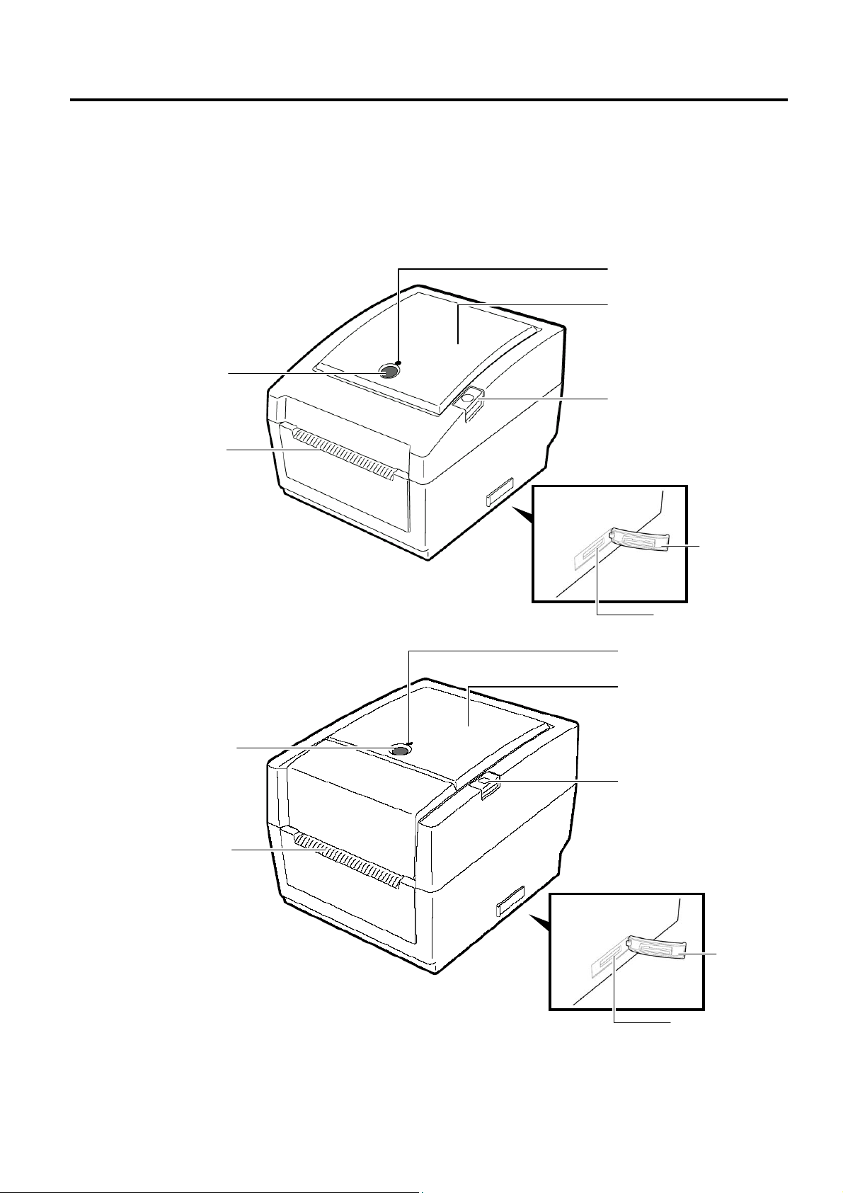
1.1.1 Front View
(1) B-EV4D
FEED Button
Media Outle
(2) B-EV4T
FEED Button
Media Outle
STATUS Lamp
Media View Window
Top Cover Release Button
SD Card
Slot Cover
SD Card Slot
STATUS Lamp
Media View Window
Top Cover Release Button
SD Card
Slot Cover
SD Card Slot
1-1
Page 4
1. OUTLINE EO18-33025
t
r
r
Adj
r
1.1 Feature of the B-EV4D/EV4T
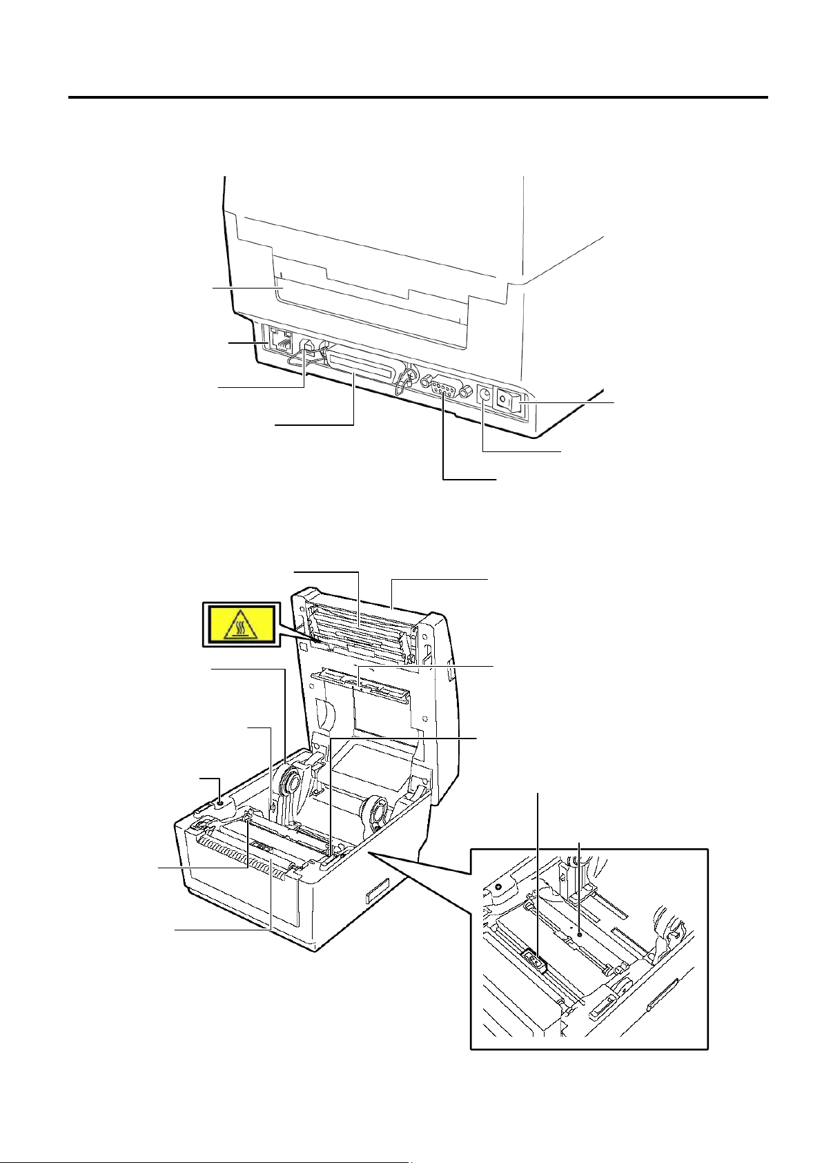
1.1.2 Rear View
Fanfold paper slo
Ethernet interface
USB Interface
Connecto
Parallel Interface
Connector (Centronics)
Power Switch
Power Jack
Serial Interface Connector (RS-232C)
1.1.3 Interior
(1) B-EV4D
Print Head
Top Cover
Media Holde
Feed Gap Sensor
(Receiver)
Media Holder Lock Switch
Cover Open Senso
Media Guide
ustment Dial
Black Mark Sensor
Feed Gap Sensor
(Transmitter)
Media Guide
Platen
1-2
Page 5
1. OUTLINE EO18-33025
r
r
r
r
r
1.1 Feature of the B-EV4D/EV4T
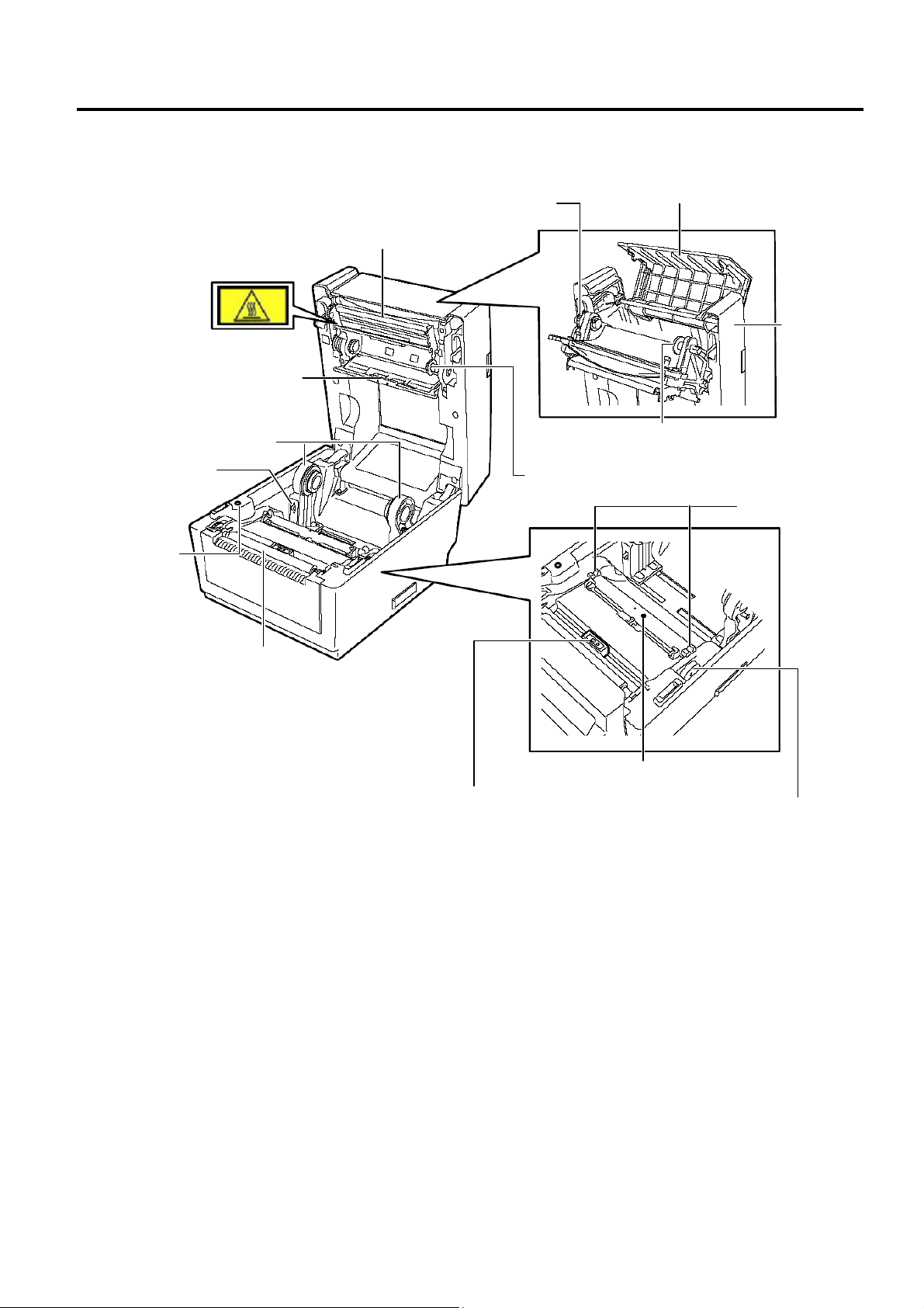
(2) B-EV4T
Ribbon Rewind Gea
Ribbon Access Cover
Print Head
Top Cover
Feed Gap Senso
(Receiver)
Media Holde
Lock Switch
Cover Open
Senso
Media Holde
Spring Guide Wheel (Supply side)
Spring Guide Wheel (Take-up side)
Media Guide
Platen
Black Mark Sensor
Feed Gap Sensor (Transmitter)
Media Guide
Adjustment Dial
1-3
Page 6

1. OUTLINE EO18-33025
1.2 Indication of the Model Name
1.2 Indication of the Model Name
B - E V 4 D - G S 14 - QM - R
RoHS compliance model
Destination country/Region code
QM: Standard for World Wide
Interface
14: USB, Serial, Parallel and Ethernet
Issue mode
S: Standard
Dot density of the print haed.
G: 8dots/mm (203dpi)
T: 12dots/mm (300dpi)
Print mode
D: Direct thermal print
T: Thermal transfer print
Print width
4: 4inch
1-4
Page 7
1. OUTLINE EO18-33025
1.3 Basic Specifications
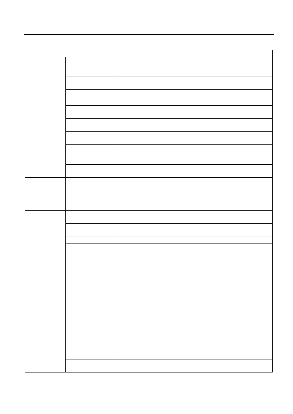
1.3 Basic Specifications
Model B-EV4D B-EV4T
General
Characteristics
Printer
characteristics
Construction Double walled casing & Clam shell design
Maintenance No tool required to repair thermal head and platen
Paper holder No roll spindle & No paper holder spring
Print method
Resolution
Print width
Direct thermal printing Direct thermal/thermal transfer
printing
GS model: 203 dpi (8 dots/mm)
TS model 300 dpi (12 dots/mm)
GS model: 203 dpi Max. 4.25” (108 mm)
TS model: 300 dpi Max. 4.17”(106mm)
Print length
Print Speed
RAM 8 MB SDRAM
Flash ROM 4 MB
User area 832 KB
Optional memory SD Card
Media sensors Feed gap sensor
I/F (User installable) RS-232C (Max. 115.2Kbps)
Barcode Linear
(Same as B-SA4
series)
Printer Language TPCL (Refer to External Equipment I/F manual)
2D Barcode
(Same as B-SV4
series)
GS model: 203 dpi, Max. 39” (999 mm)
TS model: 300 dpi, Max. 39” (999 mm)
GS model: 203 dpi, 2, 3, 4, 5”/sec, 2, 3 ips for peel-off
TS model: 300 dpi, 2, 3, 4”/sec, 2 ips for peel-off
Black mark sensor
Cover open (Reflective)
Ribbon end (Reflective encoder sensor)
Centronics (SPP)
USB 2.0 (Support Full Speed)
LAN 10/100Base
UPC-A, UPC-E, EAN8/13,
UPC-A add on 2&5,
EAN-8/13 add on 2&5,
Code39, Code93,
Code128, EAN128,
NW7, MSI,
Industrial 2 of 5,
ITF, Postnet,
RM4SCC, KIX-code,
Plessey, RSS14
Data Matrix, PDF417
Maxicode, QR code
Micro PDF417
1-5
Page 8
1. OUTLINE EO18-33025
(Revision Date: Mar. 27, 2009)
1.3 Basic Specifications
Model B-EV4D B-EV4T
Printer
characteristics
Fonts
Bitmap: Alpha-numeric 20 types + Kanji 4 types
Outline: 2 types
Writable characters, Optional TTF
LED One LED w/ 3 colors (w/ silk screen print of “STATUS”)
Key Feed key (w/ silk screen print of “ FEED”)
Switch Power S/W
Media
characteristics
Label width 1” (25.4 mm) to 4.41” (112 mm)
Label length
Label length (Strip
mode)
Label length (Cutter
mode)
203 dpi: 0.6” (15 mm) to 39” (999 mm)
300 dpi: 0.6” (15mm) to 39” (999 mm)
25.4~152.4 mm (1”~6”)
25.4~999 mm (1”~39”)
Roll diameter Max. 5” (127 mm)
Core diameter 1” (25.4 mm) to 1.5” (38 mm)
Media thickness 0.0024” (0.06 mm) to 0.0075” (0.19 mm)
Roll-fed, Fanfold, Die-cut,
Continuous, Tag stock, Receipt
1.33” (33.8 mm) to 4.30” (110
mm)
Ribbon
characteristics
Media types
Outside diameter ---------- Max. 40 mm
Standard length ---------- 110 m
Ribbon width ----------
ID core ---------- 0.5” (12.7 mm)
Operating
characteristics
Operating
temperature
41 degF (5 degC) to 104 degF (40 degC)
Storage temperature -40 degF (-40 degC) to 140 degF (60 degC)
Operating humidity 25 to 85 % (Non-condensing R.H)
Storage humidity 10 to 90 % (Non-condensing R.H)
AC Adapter: 100-240 VAC, 50/60 Hz ± 10%
Power consumption
G Type (203dpi) During standby: 100mA (2.4W)
Electrical
During a print job: 3A (72W)
T Type (300dpi) During standby: 100mA (2.4W)
During a print job: 2.5A (60W)
Rush Current
110V input: ≤45A
220V inpt: ≤90A
Agency approvals FCC Class B
C-Tick
CE
TUV
UL, cUL
CCC
VCCI Class B (Japanese model), PSE (AC adapter, Japanese
model)
Environmental
complaint
RoHS
WEEE
1-6
Page 9

1. OUTLINE EO18-33025
1.3 Basic Specifications
Model B-EV4D B-EV4T
Physical
characteristics
Width 7.8” (198 mm) 7.8” (198 mm)
Height 6.7” (169.5 mm) 6.8” (173 mm)
Depth 10.2” (258 mm) 10.2” (258 mm)
Weight 2.5Kg or less 2.5Kg or less
Related products
Options
Full cutter module (B-EV204-F-QM-R)
Partial cutter module (B-EV204-P-QM-R)
Strip module (B-EV904-H-QM-R)
External Media Holder (B-EV904-PH-QM-R)
AC Adapter Cover Kit (B-EV904-AC-QM-R)
Accessories Start–up CDROM
Power Adapter
Supply Loading Instruction
Safety Precautions
1-7
Page 10
1. OUTLINE EO18-33025
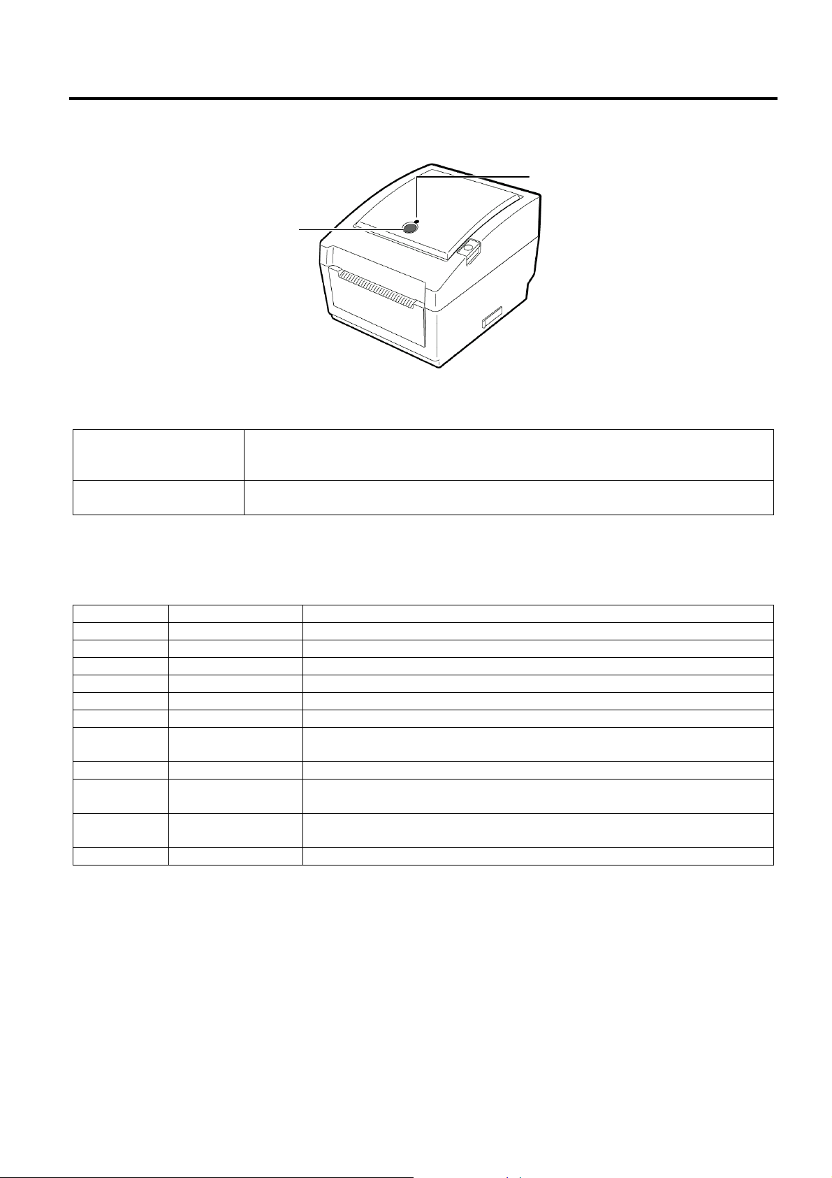
1.4 Key and LED
1.4 Key and LED
STATUS Lamp
FEED Button
The [FEED] button operates as FEED button or PAUSE button depending on the printer statuses.
Pressing this button when the printer is in online state causes a media feed.
As the FEED button
As the PAUSE button
The indicator lamp lights up or flashes in different colors depending on the printer statuses. The main
indicator lamp statuses and the corresponding printer statuses are shown inside the top cover.
Pressing this button after removing a cause of an error returns the printer to
online state.
Pressing this button during printing stops printing after completing the current
label. The printer resumes printing when this button is pressed again.
Color Status Printer status
Green Lights up Stand-by
Green Flashes fast Communicating with a host.
Green Flashes slowly Printing is temporarily stopped (paused).
Green/Red Flashes slowly The print head temperature exceeded the upper limit.
Red Lights up A communication error occurred. (Only when the RS-232C is used.)
Red Flashes fast A paper jam occurred.
Red
Red Flashes slowly An issue or feed was attempted with the top cover opened.
Orange Flashes fast
Orange
None Unlit The top cover is open.
Flashes at
medium speed
Flashes at
medium speed
The media is ended.
A paper jam occurred din the cutter unit. (Only when the cutter unit is
fitted.)
The ribbon is ended.
1-8
Page 11
1. OUTLINE EO18-33025
d
1.5 Supply Specifications
1.5 Supply Specifications
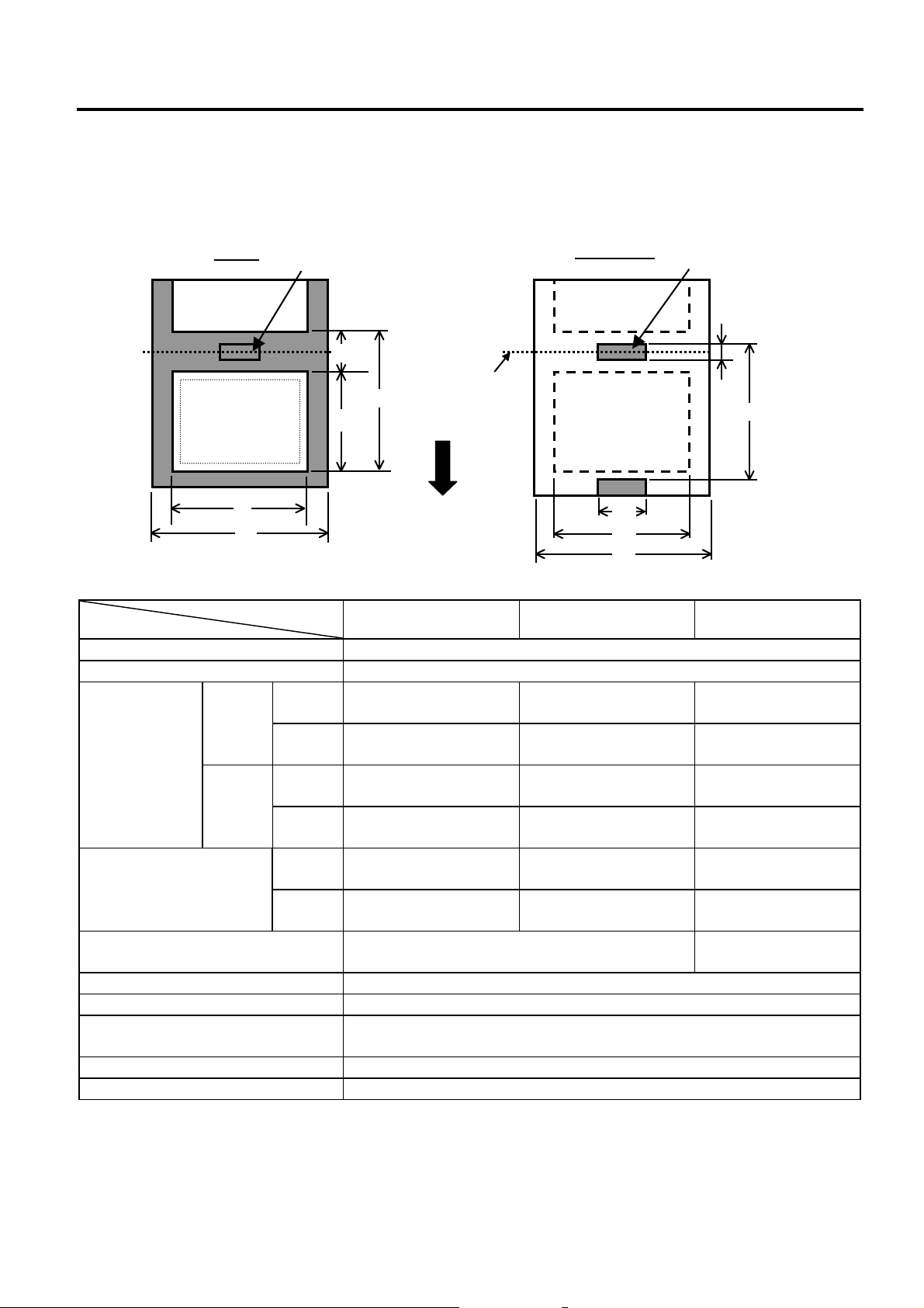
1.5.1 Media Type
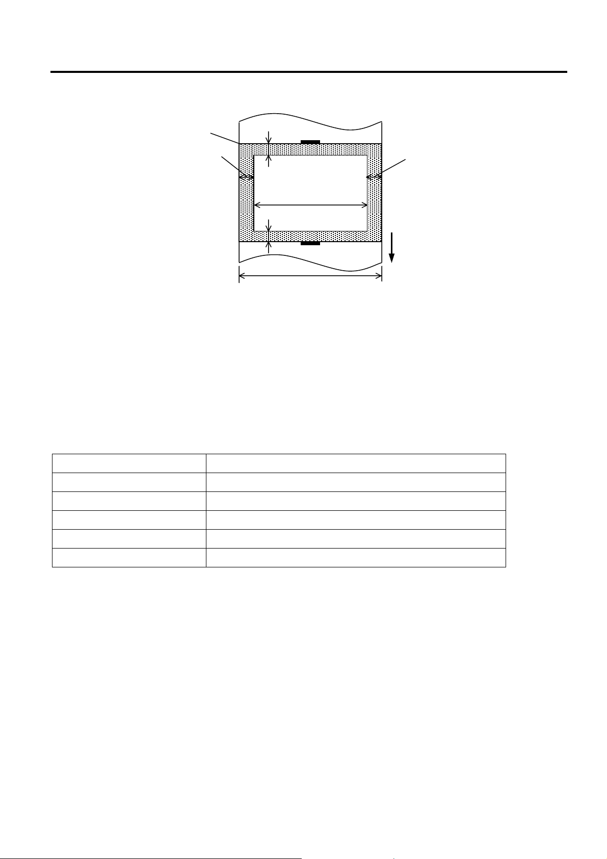
The table below shows the size and shape of the media that can be used on this printer.
Unit: mm (inch)
Item
c Width including backing paper 25.4 to 112 (1.0 to 4.41)
d Media width 22.4 to 109 (0.88 to 4.29)
e Media pitch
f Media length
g Gap/black mark length 2.0 to 10.0 (0.08 to 0.39)
h Black mark width Min. 8.0 (0.31)
Thickness 0.06 to 0.19 (0.0024 to 0.0075)
Max. outer roll diameter
Roll direction Outside (standard), Inside (Refer to NOTE 3)
Inner core diameter 25.4 to 38.1, or 76.2 (1 to 1.5, or 3)
Label
c
Issue mode
Label
Tag
Black Mark
(on reverse side)
f
203 dpi
300 dpi
203 dpi
300 dpi
203 dpi
300 dpi
Tag paper
g
Cut position
Black Mark
(on reverse side)
g
e
e
Feed Direction
h
d
c
Batch mode Strip mode Cut mode
10 to 999
(0.39 to 39.3)
10 to 457.2
(0.39 to 18.0)
10 to 999
(0.39 to 39.3)
10 to 457.2
(0.39 to 18.0)
8 to 997
(0.31 to 39.25)
8 to 455.2
(0.31 to 17.9)
Ø214 (8.42): When the optional External Media Roll Hanger is used.
25.4 to 152.4
(1.0 to 6)
25.4 to 152.4
(1.0 to 6)
-----
-----
23.4 to 150.4
(0.92 to 5.92)
23.4 to 150.4
(0.92 to 5.92)
Ø127 (5)
25.4 to 999
(1.0 to 39.3)
25.4 to 457.2
(1.0 to 18.0)
25.4 to 999
(1.0 to 39.3)
25.4 to 457.2
(1.0 to 18.0)
19.4 to 993
(1.0 to 39.1)
19.4 to 451.2
(1.0 to 17.76)
6.0 to 10.0
(0.24 to 0.39)
(See NOTE 2.)
1-9
Page 12
1. OUTLINE EO18-33025
A
±
±
1.5 Supply Specifications
NOTES:
1. To ensure print quality and print head life use only TOSHIBA TEC approved media.
2. When using a media roll of 76.2-mm (3”) inner core diameter, the 3”-Diameter Media Shaft included in
the optional External Media Roll Hanger is required.
3. Precaution for use of labels
When labels are used for printing, please only use outside wound labels.
Use of an inside wound label causes a paper jam.
Outside wound Inside wound
Label Usable Not usable
Tag Paper Usable Usable
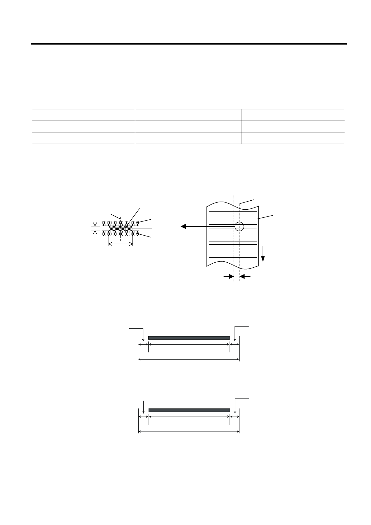
1.5.2 Detection Area of the Transmissive Sensor
The Transmissive sensor is fixed and positioned at 6.35 mm right of the center of the media path.
The Transmissive Sensor detects a gap between labels, as illustrated below.
Sensor position
Min. 2 mm
(Min. 6 mm:
cut mode)
Min. 8 mm
rea to be detected.
Label
Gap
Label
Sensor position
Print side
Media feed direction
6.35mm
1.5.3 Detection Area of the Reflective Sensor
The figure below illustrates the relation between the head effective print width and media width.
(for GS14 Type)
Out of print range
Print head element
2 mm
108.0 mm
(Head Effective Print Range)
112.0 mm (Max. media width)
0.2mm
2 mm
Out of print range
(for TS14 Type)
Out of print range
Print head element
3 mm
106.0 mm
(Head Effective Print Range)
112.0 mm (Max. media width)
0.2mm
Out of print range
3 mm
1-10
Page 13
1. OUTLINE EO18-33025
1.5 Supply Specifications
The figure below shows the effective print area on the media.
1.5mm from the left edge of media
Start line
1mm
1.5mm from the right edge of media
Guaranteed print area
1mm
Media feed direction
(Backing paper width is not included.)
Media width
NOTES:
1. Be sure not to print on the 1.5-mm wide area from the media edges (shaded area in the above figure).
2. The centre of media should be positioned at the centre of the print head.
3. Print quality is not guaranteed within 3 mm from the print head stop position (including 1-mm slow-up.)
4. Average print (black) rate should be 15% or less. For bar code print area, the print rate should be 30%
or less.
5. Line weight should be 3 to 12 dots.
1.5.4 Ribbon
Type Spool type
Width 33.8 mm to 110 mm
Length Depends on its thickness and outside diameter of core.
Max. outside diameter
∅40 mm
Inside diameter of core 12.7 mm
Roll direction Outside
NOTES:
1. To ensure print quality and print head life use only TOSHIBA TEC specified ribbons.
2. Too much difference in width between media and ribbon may cause ribbon wrinkles. To avoid ribbon
wrinkles use a ribbon for proper media width shown in the above table. Do not use a ribbon that is
narrower than media.
3. When discarding ribbons, please follow the local rule.
1-11
Page 14
2. ELECTRONICS SPECIFICATIONS EO18-33025
2.1 Block Diagram
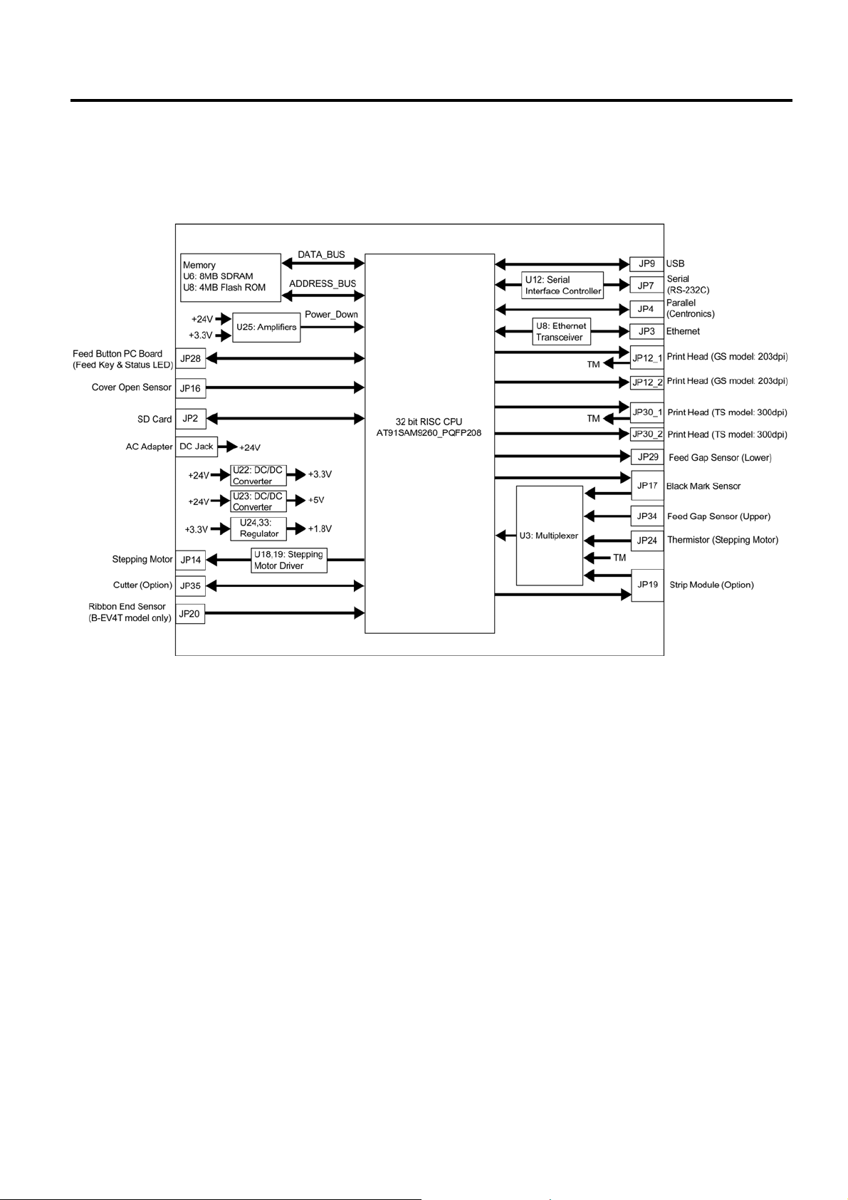
2. ELECTRONIC SPECIFICATIONS
2.1 Block Diagram
2-1
Page 15
2. ELECTRONICS SPECIFICATIONS EO18-33025
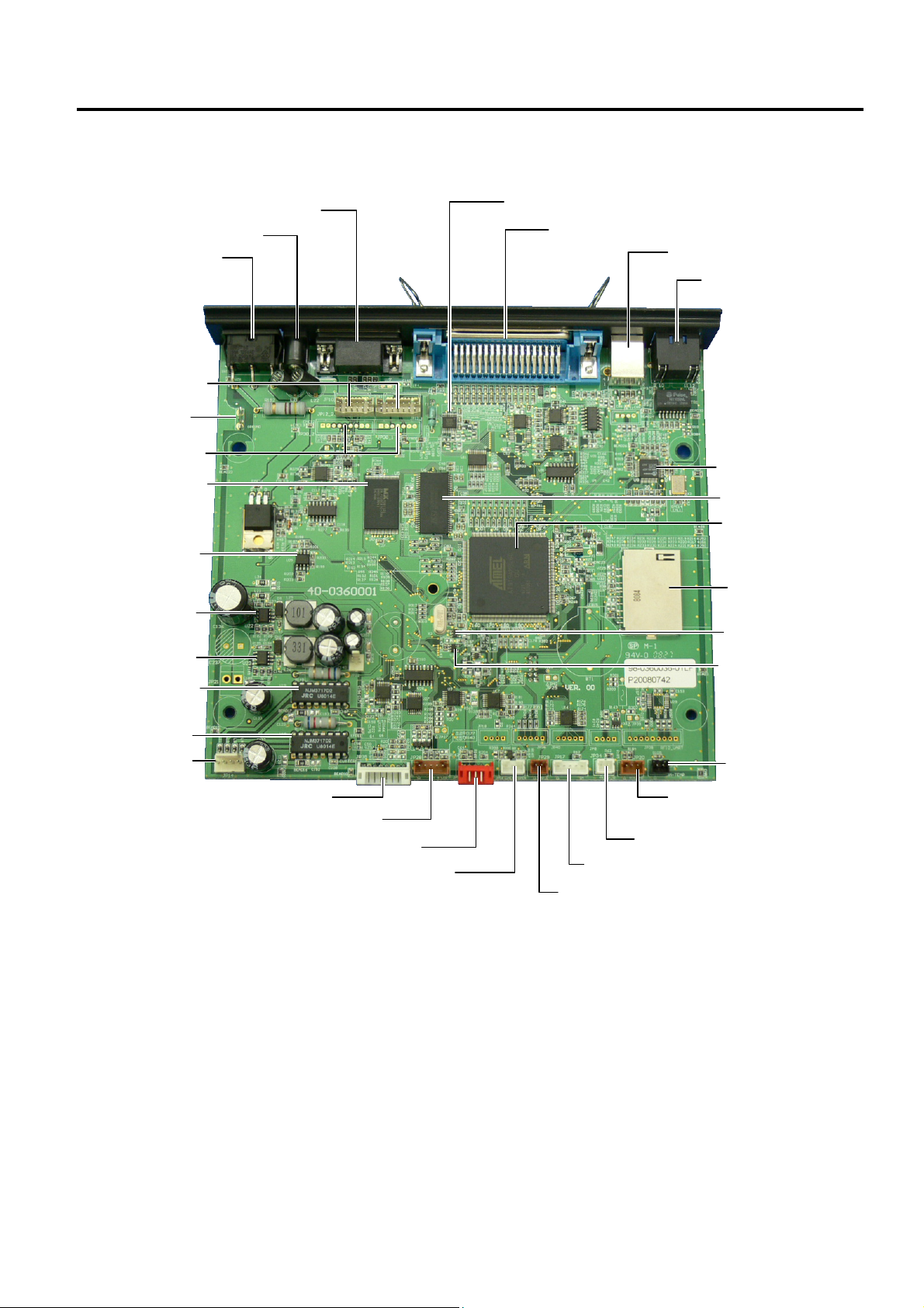
2.2 Main PC Board Layout
SW1: Power Switch
JP12: Print Head
GS model: 203dpi
Ground Terminal
JP30: Print Head
TS model: 300dpi
U5: Flash ROM
U25: Amplifier
(Reset Detect)
U22: DC/DC Converter
U23: DC/DC Converter
U19: Stepping Motor Driver
U18: Stepping Motor Driver
JP14: Stepping Motor
JP7: Serial (RS-232C)
DC Jack
JP35: Cutter Module
JP28: Feed Key/Status LED
JP19: Strip Module
JP16: Cover Open Sensor
U12: Serial Interface Controller
JP4: Parallel (Centronics)
JP34: Feed Gap Sensor (Upper)
JP17: Black Mark Sensor
JP29: Feed Gap Sensor (Lower)
2.2 Main PC Board Layout
JP9: USB
JP3: Ethernet
(10BASET/100BASETX)
U8: Ethernet Transceiver
U6: SDRAM
U2: 32bit RISC CPU
AT91SAM9260
JP2: SD Card Slot
U33: Regulator
U24: Regulator
JP24: Thermistior
(Stepping Motor)
JP20: Ribbon End Sensor
(B-EV4T model)
2-2
Page 16
2. ELECTRONICS SPECIFICATIONS EO18-33025
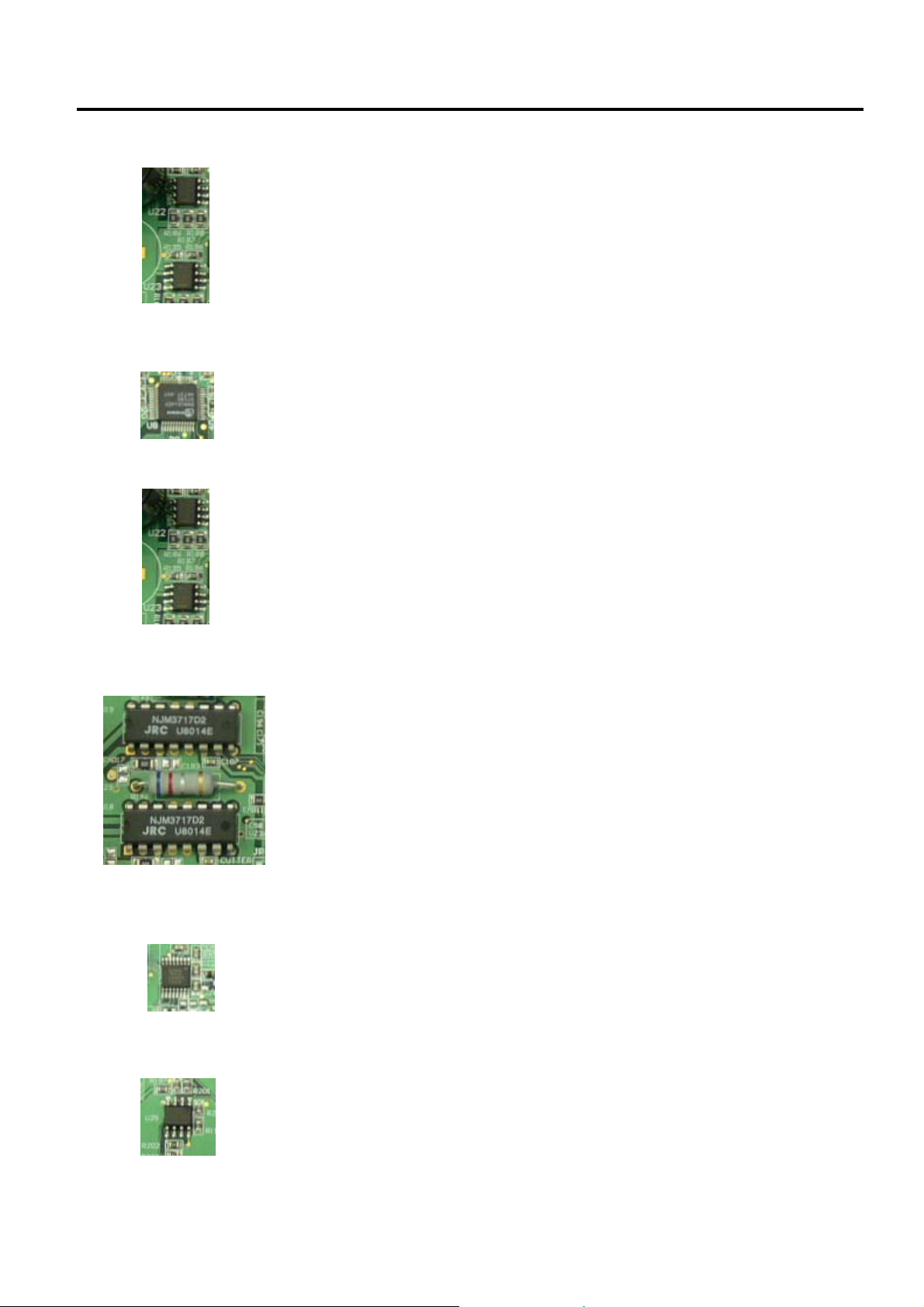
2.3 Description of the Main PC Board
2.3 Description of the MAIN PC Board
This PC board, the brain of the printer, is comprised of the following components.
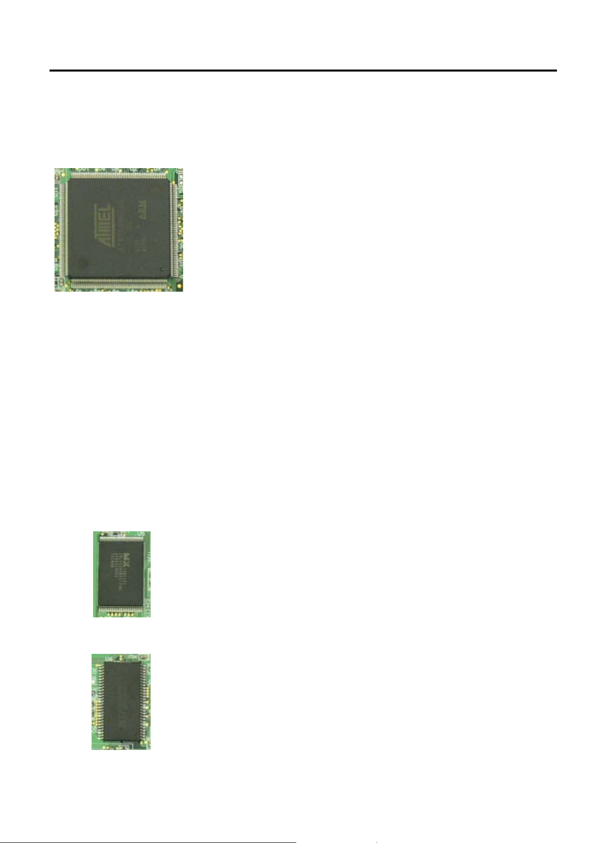
32bit RISC CPU (U2): Type: AT91SAM9260
The 32bit RISC CPU operates the following processing:
Controlling the interfaces
• Serial Interface (RS-232C)
• Parallel Interface (Centronics)
• Eternet (10BASET/100BASETX)
Controlling the Status LED
Detect the [Feed] key
Controlling the read/write operation on the memory
• Flash ROM
• SDRAM
• SD Card
Controlling the options
• Cutter Module
• Strip Module
Control and detect sensor statuses
• Ribbon Sensor
• Cover Open Sensor
• Feed Gap Sensor
• Black Mark Sensor
• Motor Temperature Thermistor
Controlling the Print Head
Flash ROM (U5): Type: MX29LV320CBTC-70G
Capacity: 32M bit
The programmed data of the boot program, main program, C/G, writable
character are written into the flash ROM.
SDRAM (U6): Type: IS42S16400B-6TL
Capacity: 64M bit
It is used for drawing the print data and used as a work area.
2-3
Page 17
2. ELECTRONICS SPECIFICATIONS EO18-33025
2.3 Description of the Main PC Board
DC/DC Converter (U22, 23): Type: TS34063
It generates the voltages (+5V, +3.3V) from the power supply voltage
(AC adapter).
+5V and +3.3V are used as the operating voltage for each circuit.
Eternet Transceiver (U8): Type: DM9161
This IC is used for controlling the Ethernet (10BASET/10BASETX).
Regulator (U24, U33): Type: TS68N28CX5, TS9007DCX
It generates the voltages (+1.8) from the DC/DC converter voltage
(+3.3V).
Stepping Motor Driver (U18, U19): Type: PBL3717
This IC is used for controlling the Stepping Motor.
Serial Interface Controller (U12): Type: SP3232ECY
This IC is used for controlling the Serial Interface (RS-232C).
Reset detect circuit (U25): Type: TS358
This IC is single supply dual operation amplifiers.
It detects the voltage depression from +24V and +3.3V and outputs the
Power Down signal to the CPU.
2-4
Page 18
2. ELECTRONICS SPECIFICATIONS EO18-33025
2.3 Description of the Main PC Board
JP2 (SD Card Slot): Type: MS3B11-KAA-0
This connector is connected to the SD Card.
Note: Recommended SD card specification.
• Supported DOS FAT file system.
SD V 2.0 (SDHC): 4GByte Class 6
Signal
CD/DAT3 1
CMD 2
VSS1 3
VDD 4
CLK 5
VSS2 6
DAT0 7
DAT1 8
DAT2 9
GND 10
GND 11
CD 12
WP 13
Pin
No.
• Folders stored in the SD card should be in the 8.3 filename format.
• Approved SD card manufacturers: SanDisk, Transcend.
SD V 1.0, V 1.1: 128MByte, 256MByte, 512MByte, 1GByte
JP3 (Ethernet): Type: RJ45 with 2LEDs (Yellow and Green)
This connector is used for the Ethernet (10BASET/100BASETX).
Signal
Tx+ 1
Tx- 2
Rx+ 3
N/C 4
N/C 5
Rx- 6
N/C 7
N/C 8
Cathode of
the Yelleo LED
+3.3V (Anode of
the Yellow LED
Cathode of
the Green LED
+3.3V (Anode of
the Green LED
Pin
No.
9
10
11
12
2-5
Page 19

2. ELECTRONICS SPECIFICATIONS EO18-33025
2.3 Description of the Main PC Board
JP4 (Parallel Interfcae): This connector is used for the Parallel (Centronics) interface.
Signal
Strobe 1
Data0 2
Data1 3
Data2 4
Data3 5
Data4 6
Data5 7
Data6 8
Data7 9
Ack 10
Busy 11
Paper Out / End 12
Select 13
GND 14
No Defined 15
GND 16
GND 17
No Defined 18
GND 19
GND 20
GND 21
GND 22
GND 23
GND 24
GND 25
GND 26
GND 27
GND 28
GND 29
GND 30
No Defined 31
Error / Fault 32
GND 33
GND 34
GND 35
No Defined 36
Pin
No.
Pin SPP Mode Nibble Mode I/O Function
A low on this line indicates that there
1 Strobe N/A I
2-9 Data 0-7 N/A I Data Bus. Single-directional.
10 Ack N/A O
11 Busy N/A Ot
12 Paper Out / End N/A O
13 Select N/A O Extensibility flag
14 Ground N/A GND Ground
15 No Defined N/A N/A
16-17 Ground N/A GND Ground
18 No Defined N/A N/A
19-30 Ground N/A GND Ground
31 No Defined N/A N/A
32 Error / Fault N/A O
33-35 Ground N/A GND Ground
36 No Defined N/A N/A
are valid data at the host. When this
pin is de-asserted, the +ve clock edge
should be used to shift the data into
the device.
A low on this line indicates that there
are valid data at the Device. When this
pin is de-asserted, the +ve clock edge
should be used to shift the data into
the host.
When in reverse direction, a high
indicates data, while a low indicates a
command cycle. In forward direction, it
functions as PtrBusy.
When low, device acknowledges
reverse request.
A low set by the device indicates that
the reverse data is available
JP7 (Serial Interface): Type: D-Sub 9pin
This connector is used for the Serial (RS-232C) interface.
+5V is output from the pin 1.
The TXD signal is a serial signal and output from the pin 2.
The RXD signal is a serial signal and input into the pin 3.
Signal
+5 V 1
TXD 2
RXD 3
CTS 4
GND 5
RTS 6
N/C 7
RTS 8
N/C 9
Pin
No.
2-6
Page 20

2. ELECTRONICS SPECIFICATIONS EO18-33025
2.3 Description of the Main PC Board
JP9 (USB): Type: Type B Connector
This connector is used for the USB interface.
Signal
+5 V 1
D- 2
D+ 3
N/C 4
GND 5
Pin
No.
JP12 (Print Head): This connector is connected to the print head (for GS model, 203dpi).
The voltages and signals for controlling the print head are input/output
JP12-1
into/from the connector.
Signal
VH (+24V) 1
VH (+24V) 2
VH (+24V) 3
VH (+24V) 4
GND 5
GND 6
/STB2 7
NC 8
TM 9
TM 10
VDD (+5V) 11
GND 12
/STB1 13
GND 14
Pin
No.
JP12-2
Signal
CLK 1
GND 2
GND 3
GND 4
DI 5
/LAT 6
GND 7
GND 8
VH (+24V) 9
VH (+24V) 10
VH (+24V) 11
VH (+24V) 12
Pin
No.
2-7
Page 21

2. ELECTRONICS SPECIFICATIONS EO18-33025
2.3 Description of the Main PC Board
JP14 (Stepping Motor): This connector is connected to the Stepping Motor.
Signal
MB (PHASE1) 1
MA (PHASE1) 2
MB (PHASE2) 3
MA (PHASE2) 4
Pin
No.
JP16 (Cover Open Sensor): This connector is connected to the Cover Open Sensor.
Signal
+3.3V 1
HEAD 2
GND 3
Pin
No.
JP17 (Black Mark Sensor): This connector is connected to the Black Mark Sensor.
Signal
N.C. 1
+3.3V 2
BM_E 3
BM_R 4
+3.3V 5
Pin
No.
JP19 (Strip Module): This connector is connected to the Strip Module.
Signal
+3.3V 1
PEEL_SW 2
PEEL_E 3
PEEL_R 4
GND 5
Pin
No.
JP20 (Ribbon End Sensor): This connector is connected to the Ribbon End Sensor. (B-EV4T model
Signal
+3.3V 1
RIB_END 2
GND 3
Pin
No.
only)
2-8
Page 22

2. ELECTRONICS SPECIFICATIONS EO18-33025
2.3 Description of the Main PC Board
JP24 (Stepping Motor Thermistior): This connector is connected to the Stepping Motor Thermistor.
MOTOR TEMP signal is temperature of the stepping motor.
Signal
MOTOR TEMP 1
GND 2
Pin
No.
JP28 (Feed Key/Status LED): This connector is connected to the Feed Key and Status LED.
Signal
+3.3V 1
GREEN_LED 2
RED_LED 3
T_KEY 4
GND 5
Pin
No.
JP29 (Feed Gap Sensor, Lower): This connector is connected to the Lower Feed Gap Sensor (Photo
Diode).
Signal
+3.3V 1
GAP_E 2
Pin
No.
Print Head (JP30): This connector is connected to the print head (for TS model, 300dpi).
The voltages and signals for controlling the print head are input/output
JP30-1
Signal
VH (+24V) 1
VH (+24V) 2
TM 3
TM 4
/STB2 5
GND 6
GND 7
JP30-2
Signal
GND 1
GND 2
VDD (+5V) 3
/STB1 4
/LAT 5
CLK 6
DI 7
VH (+24V) 8
VH (+24V) 9
Pin
No.
Pin
No.
into/from the connector.
2-9
Page 23

3. REPLACING THE IMPORTANT PARTS EO18-33025
!
(Revision Date: Mar. 27, 2009)
3.1 Replacing the Top Cover
3. REPLACING THE IMPORTANT PARTS
1. Turn off the power switch and disconnect the DC plug of the AC Adapter and the
RS-232C cable before replacing any parts.
2. Follow all manual instructions. Failure to do so could create safety hazards such as
fire or electrocution.
CAUTION!
1. To protect the connector pins or component from static discharge, do not touch them
with bear hand.
2. Use electrostatic free form and the original carton for transportation.
3. Keep your work environment static free to avoid damage to the printer.
4. Do not remove any connectors from the printer within 10 sec. after unplugging the
power cord.
WARNING
NOTES:
1. Manual instructions must be followed when installing option kits or adding cables to
avoid system failures and to insure proper performance and operation.
2. Failure to follow manual instructions or any unauthorized modifications, substitution or
change to this product will void the limited product warranty.
Lubrication
CAUTION!
1. Lubrication: During parts replacement
2. Kinds of oil: FLOIL G-488: 1kg can (part No.: 19454906001)
Any machine is generally in its best condition when delivered; therefore, it is necessary to try to
keep this condition. Unexpected failure occurs due to lack of oil, debris, or dust. To keep its
best condition, periodically clean the machine and apply proper kinds of oil to each part in
which lubrication is needed. Although the frequency of lubrication varies according to how
much the machine is used, at least it is necessary to lubricate before the machine becomes dry.
It is also necessary to wipe off excessive oil as it collects dirt.
NOTE: Before replacing the important parts, store the printer parameter data on a PC with the B-EV4
setting tool. Uploading the data from the PC to the printer after replacement restores the
printer parameter setting to the status prior to replacement. Regarding the details of B-EV4
setting tool, refer to the B-EV4 Setting Tool Specification posted on the Barcode Knowledge Pot.
URL of Barcode Knowledge Pot
http://barcode.toshibatec.co.jp/Ris/products/barcode/support/en/index.php
3-1
Page 24

3. REPLACING THE IMPORTANT PARTS EO18-33025
r
T
r
r
r
(Revision Date: Mar. 27, 2009)
3.1 Replacing the Top Cover
3.1 Replacing the Top Cover
3.1.1 B-EV4T model
1. Press down the top cover release button to unlock the top cover, then fully open the top
cover.
Top Cove
Top Cover
Release Button
2. Use the Phillips screwdriver to remove the 6 screws from the top inner cover.
Top Cove
-3x6 Screw
Top Inner Cove
3. Disconnect the connector from the feed button PC board.
Feed Button PC Board
Connecto
3-2
Page 25

3. REPLACING THE IMPORTANT PARTS EO18-33025
r
T
r
(Revision Date: Mar. 27, 2009)
3.1 Replacing the Top Cover
4. Remove the top cover.
5. Replace the top cover with a new one, then reassemble in the reverse order of
removal.
Top Cover
3.1.2 B-EV4D model
1. Press down the top cover release button to unlock the top cover, then fully open the top
cover.
Top Cove
Top Cover
Release Button
2. Use the Phillips screwdriver to remove the 6 screws from the top inner cover.
Top Cover
Top Inner Cove
-3x10 Screw
3-3
Page 26

3. REPLACING THE IMPORTANT PARTS EO18-33025
r
r
r
(Revision Date: Mar. 27, 2009)
3.2 Replacing the Lower Cover
3. Release the media view window hooks which hold the top cover together with the top
inner cover.
Top Inner Cover
Top Cove
Hook
Media View Window
4. Upward move the top cover release levers, and then release the top cover from the top
inner cover.
Top Inner Cove
Top Cover
Top Cover Release Leve
3-4
Page 27

3. REPLACING THE IMPORTANT PARTS EO18-33025
(Revision Date: Mar. 27, 2009)
3.2 Replacing the Lower Cover
5. Disconnect the connector from the feed button PC board.
Feed Button PC Board
Connector
6. Remove the top cover.
7. Replace the top cover with a new one, then reassemble in the reverse order of
removal.
3-5
Page 28

3. REPLACING THE IMPORTANT PARTS EO18-33025
T
r
(Revision Date: Mar. 27, 2009)
3.2 Replacing the Lower Cover
3.2 Replacing the Lower Cover
1. Turn the printer upside down and use the Phillips screwdriver to remove the 6 screws.
2. Remove the lower cover.
3. Replace the lower cover with a new one, then reassemble in the reverse order of
Lower Cove
removal.
-3x12 Screw
3-6
Page 29

3. REPLACING THE IMPORTANT PARTS EO18-33025
T
(Revision Date: Mar. 27, 2009)
3.3 Replacing the Main PC Board
3.3 Replacing the Main PC Board
1. Refer to section 3.2 to remove the lower cover.
2. Remove the screw from the main PC board.
3. Disconnect all connectors from the main PC board.
Main PC Board
-3x6 Screw
4. Use the Phillips screwdriver to remove the 2 screws and use the socket wrench to
remove the 2 bolts.
P-2x7 Screw
Bolt
5. Detach the interface plate and the black mylar from the main PC board.
Main PC Board Black Mylar
Interface Plate
3-7
Page 30

3. REPLACING THE IMPORTANT PARTS EO18-33025
(Revision Date: Mar. 27, 2009)
3.3 Replacing the Main PC Board
6. Replace the main PC board with a new one, then reassemble in the reverse order of
removal.
7. After replacement, perform the following operations.
● Perform a media sensor calibration with the button of the printer or B-EV4 Setting
Tool.
Regarding the media sensor calibration, refer to the Owner’s Manual or the B-EV4
Setting Tool Specification posted on the Barcode Knowledge Pot.
URL of Barcode Knowledge Pot:
http://barcode.toshibatec.co.jp/Ris/products/barcode/support/en/index.php
● Perform a printer parameter setting with the B-EV4 Setting Tool.
● Perform an interface setting (RS-232C, Eternet) with the B-EV4 Setting Tool.
NOTE: It is possible to save/upload the printer parameter and interface setting
into/from the PC with the B-EV4 Setting Tool.
8. Also, make sure the printer performs correctly for the following points.
• The sensor adjustment is performed correctly.
• Printing is performed correctly during the diagnostic test print.
• When the PC connected to the printer sends sample data to the printer, printing is
performed correctly.
NOTE: Firmware download onto the Main PC board
Perform a firmware download onto the Main PC board if necessary (in the case of
alteration/addition to the specification).
Regarding the download procedure, refer to Firmware Down Loading Procedure
which is posted on the Barcode Knowledge Pot. The firmware program to be
downloaded is also available from this website.
3-8
Page 31

3. REPLACING THE IMPORTANT PARTS EO18-33025
(Revision Date: Mar. 27, 2009)
3.4 Replacing the Platen Ass’y
3.4 Replacing the Platen Ass’y
1. Refer to section 3.1 to open the top cover.
2. Release the platen holder tabs from the lower inner cover and vertically raise them.
3. Remove the platen ass’y.
Platen Holder Tab
Platen Ass’y
4. Replace the platen ass’y with a new one, then reassemble in the reverse order of
removal.
5. After replacing, perform a diagnostic test print or print a sample label to make sure the
printer performs correctly for the following points.
• The label is issued correctly.
• No noise is generated during the print operation.
• None of blurred print, smudge, etc. is generated.
3-9
Page 32

3. REPLACING THE IMPORTANT PARTS EO18-33025
r
(Revision Date: Mar. 27, 2009)
3.5 Replacing the Print Head Ass’y
3.5 Replacing the Print Head Ass’y
CAUTION!
1. NEVER touch the element when handling the Print Head.
2. NEVER touch the connector pins to avoid a breakdown of the Print Head by static
electricity.
3.5.1 B-EV4T model
1. Refer to section 3.1 to open the top cover.
2. Open the ribbon access cover.
Ribbon Access Cove
3. Remove the two screws which secure the print head ass’y.
Print Head Ass’y
Screw
Screw
3-10
Page 33

3. REPLACING THE IMPORTANT PARTS EO18-33025
r
(Revision Date: Mar. 27, 2009)
3.5 Replacing the Print Head Ass’y
4. Remove the connector from the print head ass’y.
5. Remove the print head ass’y.
Connecto
Print Head Ass’y
6. Replace the print head ass’y with a new one, then reassemble in the reverse order of
removal.
[ Print head element side ] [ Print head bracket side ]
Bracket
Spring Plate
NOTE: Do not disassemble the print head ass'y which contains the bracket and the spring
plate.
7. After replacing, perform a diagnostic test print or print a sample label to make sure the
printer performs correctly for the following points.
• Printing is performed correctly.
• None of dot missing is generated.
• None of blurred print, stain, chipped bar code or characters, wrinkle, smudge,
uneven print, etc. is generated.
• Reading the bar code is possible.
3-11
Page 34

3. REPLACING THE IMPORTANT PARTS EO18-33025
r
(Revision Date: Mar. 27, 2009)
3.5 Replacing the Print Head Ass’y
3.5.2 B-EV4D model
1. Refer to section 3.1 to open the top cover.
2. The print head block is secured to the top inner cover with the latches.
Push both sides of the bracket and pull the print head block.
Bracket
Print Head Block
Top Inner Cove
Latch
3-12
Page 35

3. REPLACING THE IMPORTANT PARTS EO18-33025
r
(Revision Date: Mar. 27, 2009)
3.5 Replacing the Print Head Ass’y
3. Remove the two pins which secure the print head ass’y.
Pin
Print Head Ass’y
4. Remove the connector from the print head ass’y.
5. Remove the print head ass’y.
Print Head Ass’y
Pin
Connecto
NOTE: Do not bend or damage the spring plates when removing and reassembling the
print head ass’y.
Spring Plate
Print Head Ass’y
3-13
Page 36

3. REPLACING THE IMPORTANT PARTS EO18-33025
(Revision Date: Mar. 27, 2009)
3.5 Replacing the Print Head Ass’y
6. Replace the print head ass’y with a new one, then reassemble in the reverse order of
removal.
[ Print head element side ] [ Print head bracket side ]
Head
Element
Bracket
Spring Plate
Be careful of the following points when reassembling the print head ass’y. Hook both
openings on the bracket to the bosses. It is easy to assemble the bracket by hooking one
opening at a time. Also, do not touch or scratch the print head element.
Bracket
Boss Bracket
NOTE: Do not disassemble the print head ass'y which contains the bracket and the spring
plate.
7. After replacing, perform a diagnostic test print or print a sample label to make sure the
printer performs correctly for the following points.
• Printing is performed correctly.
• None of dot missing is generated.
• None of blurred print, stain, chipped bar code or characters, wrinkle, smudge,
uneven print, etc. is generated.
• Reading the bar code is possible.
3-14
Page 37

3. REPLACING THE IMPORTANT PARTS EO18-33025
r
(Revision Date: Mar. 27, 2009)
3.6 Replacing the Stepping Motor
3.6 Replacing the Stepping Motor
1. Refer to section 3.2 to remove the lower cover.
2. Disconnect the stepping motor connector from the main board.
3. Use the Phillips screwdriver to remove the 2 screws.
Stepping Moto
Stepping Motor
Connector (JP14)
4. Remove the stepping motor. The plastic parts for mounting the stepping motor and
thermistor appear.
SM-3x10 Screw
Thermistor
300 DPI model
motor mounting
location
203 DPI model
motor mounting
location
3-15
Page 38

3. REPLACING THE IMPORTANT PARTS EO18-33025
(Revision Date: Mar. 27, 2009)
3.6 Replacing the Stepping Motor
5. Replace the stepping motor with a new one, then reassemble in the reverse order of
removal. Be sure to apply FLOIL to the gear when reassembling.
LUBRICATION
Gear: FLOIL
NOTE:
Make sure that the stepping motor is mounted in the correct position and the thermal
conductive grease is applied to the thermistor to keep good contact with the stepping
motor case.
6. After replacing, perform a diagnostic test print or print a sample label to make sure the
printer performs correctly for the following points.
• Printing is performed correctly.
• No noise is generated during the print operation.
3-16
Page 39

3. REPLACING THE IMPORTANT PARTS EO18-33025
(Revision Date: Mar. 27, 2009)
3.7 Replacing the Gear Cover
3.7 Replacing the Gear Cover
1. Refer to section 3.2 to remove the lower cover.
2. Use the Phillips screwdriver to remove the 4 screws.
3. Remove the gear cover.
4. Remove the each gear.
Gear Cover
NOTE: Between 200 dpi printer and 300 dpi printer, the number of gears and the position
SM-3x6 Screw
of the motor pulley differ. Be careful of the orientation of the gear when replacing.
300dpi model
Motor Pulley
LUBRICATION
Gear: FLOIL
200dpi model
Motor Pulley
LUBRICATION
Gear: FLOIL
3-17
Page 40

3. REPLACING THE IMPORTANT PARTS EO18-33025
(Revision Date: Mar. 27, 2009)
3.7 Replacing the Gear Cover
5. Replace the gear cover and the each gears with a new one, then reassemble in the
reverse order of removal. Be sure to apply FLOIL to the gear when reassembling.
3-18
Page 41

3. REPLACING THE IMPORTANT PARTS EO18-33025
r
T
3.8 Replacing the Feed Button PC Board
(Revision Date: Mar. 27, 2009)
3.8 Replacing the Feed Button PC Board
1. Refer to section 3.1 to remove the top cover.
2. Remove the screws which fix the feed button PC board and the mylar sheet to the
mechanism.
-3x6 Screw
B-EV4D model
Feed Button PC Board
B-EV4T model
Mylar Sheet
Top Cove
Mylar Sheet
3. Replace the feed button PC board with a new one, then reassemble in the reverse
order of removal.
4. After replacing, make sure the printer performs correctly for the following points.
• When the printer is turned on and then the top cover is opened, the status lamp gets
unlit.
• Next, when the top cover is closed, the status lamp lights up in green.
• When the [FEED] button is pressed during the unloading of a media, the status lamp
flashes in red.
3-19
Page 42

3. REPLACING THE IMPORTANT PARTS EO18-33025
T
r
(Revision Date: Mar. 27, 2009)
3.9 Replacing the Cover Open Sensor
3.9 Replacing the Cover Open Sensor
1. Refer to section 3.1 to remove the top cover.
2. Remove the sensor connector from the main PC board.
Main PC Board
Sensor Connector(JP16)
3. Use the Phillips screwdriver to remove the screw from the cover open sensor.
-2x4 Screw
Cover Open Senso
4. Replace the cover open sensor with a new one, then reassemble in the reverse order
of removal.
5. After replacing, make sure the printer performs correctly for the following points.
• When the printer is turned on and then the top cover is opened, the status lamp gets
unlit.
• Next, when the top cover is closed, the status lamp lights up in green.
3-20
Page 43

3. REPLACING THE IMPORTANT PARTS EO18-33025
T
(Revision Date: Mar. 27, 2009)
3.10 Replacing the Ribbon Sensor (B-SV4T model only)
3.10 Replacing the Ribbon Sensor (B-SV4T model only)
1. Refer to section 3.1 to remove the top cover.
2. Remove the sensor connector from the main PC board.
Main PC Board
Sensor Connector (JP20)
3. Use the Phillips screwdriver to remove the screw from the ribbon sensor.
-2x4 Screw
Ribbon Sensor
4. Replace the ribbon sensor with a new one, then reassemble in the reverse order of
removal.
5. After replacing, make sure the printer performs correctly for the following points.
• Printing is performed correctly and the ribbon is not slack or wrinkled.
• When the ribbon is unloaded and the thermal transfer printing is performed, an error
occurs. (The ribbon sensor detects the status correctly.)
3-21
Page 44

3. REPLACING THE IMPORTANT PARTS EO18-33025
(Revision Date: Mar. 27, 2009)
3.11 Replacing the Black Mark Sensor
3.11 Replacing the Black Mark Sensor
1. Refer to section 3.1 to remove the top cover.
2. Remove the sensor connector from the main PC board.
3. Use the Phillips screwdriver to remove the 2 screws from the mylar sheet.
4. Remove the mylar sheet.
Sensor Connector (JP17)
Main PC Board
Mylar Sheet
FLT-3x6 Screw
5. Use the Phillips screwdriver to remove the screw from the sensor plate.
6. Remove the sensor plate.
Sensor Plate
7. Remove the black mark sensor.
Black Mark Sensor
T-1.5x4 Screw
3-22
Page 45

3. REPLACING THE IMPORTANT PARTS EO18-33025
(Revision Date: Mar. 27, 2009)
3.11 Replacing the Black Mark Sensor
8. Replace the black mark sensor with a new one, then reassemble in the reverse order
of removal.
9. After replacing, perform a black mark sensor calibration with the button of the printer or
the B-EV4 Setting Tool. Failure to do this may cause a sensor error.
Regarding the calibration with the button of the printer, refer to the Owner’s Manual.
Regarding the calibration with the B-EV4 Setting Tool, refer to the B-EV4 Setting Tool
Specification posted on the Barcode Knowledge Pot.
URL of Barcode Knowledge Pot
http://barcode.toshibatec.co.jp/Ris/products/barcode/support/en/index.php
10. Also, make sure the black mark sensor performs correctly for the following points.
• When the PC connected to the printer sends sample data to the printer, printing is
performed correctly. (Specify the black mark sensor as the media sensor.)
• When the [FEED] button is pressed during the unloading of a media, the status lamp
flashes in red.
3-23
Page 46

3. REPLACING THE IMPORTANT PARTS EO18-33025
T
T
3.12 Replacing the Feed Gap Sensor (Lower)
(Revision Date: Mar. 27, 2009)
3.12 Replacing the Feed Gap Sensor (Lower)
1. Refer to section 3.1 to remove the top cover.
2. Use the Phillips screwdriver to remove the 2 screws from the mylar sheet.
3. Remove the mylar sheet.
Mylar Sheet
-3x6 Screw
FL
4. Remove the sensor connector from the main PC board.
5. Use the Phillips screwdriver to remove the screw from the sensor plate.
6. Remove the sensor plate.
7. Remove the feed gap sensor (lower).
Main PC
Board
Sensor Connector
(JP29)
8. Replace the feed gap sensor (lower) with a new one, then reassemble in the reverse
order of removal.
-1.5x4 Screw
Sensor plate
Feed Gap Sensor (lower)
3-24
Page 47

3. REPLACING THE IMPORTANT PARTS EO18-33025
(Revision Date: Mar. 27, 2009)
3.12 Replacing the Feed Gap Sensor (Lower)
9. After replacing, perform a feed gap sensor (lower) calibration with the button of the
printer or the B-EV4 Setting Tool. Failure to do this may cause a sensor error.
Regarding the calibration with the button of the printer, refer to the Owner’s Manual.
Regarding the calibration with the B-EV4 Setting Tool, refer to the B-EV4 Setting Tool
Specification posted on the Barcode Knowledge Pot.
URL of Barcode Knowledge Pot
http://barcode.toshibatec.co.jp/Ris/products/barcode/support/en/index.php
10. Also, make sure the feed gap sensor performs correctly for the following points.
• When the PC connected to the printer sends sample data to the printer, printing is
performed correctly. (Specify the feed gap sensor as the media sensor.)
• When the [FEED] button is pressed during the unloading of a media, the status lamp
flashes in red.
3-25
Page 48

3. REPLACING THE IMPORTANT PARTS EO18-33025
T
r
3.13 Replacing the Feed Gap Sensor (Upper)
(Revision Date: Mar. 27, 2009)
3.13 Replacing the Feed Gap Sensor (Upper)
1. Refer to section 3.1 to remove the top cover.
2. Refer to section 3.2 to remove the lower cover.
3. Remove the sensor connector from the main PC board.
Main PC Board
Sensor Connecto
4. Use the Phillips screwdriver to remove the screw from the sensor plate.
5. Remove the sensor plate.
(JP34)
6. Remove the feed gap sensor (upper).
-1.5x4 Screw
Sensor Plate
Feed Gap Sensor (Upper)
3-26
Page 49

3. REPLACING THE IMPORTANT PARTS EO18-33025
(Revision Date: Mar. 27, 2009)
3.13 Replacing the Feed Gap Sensor (Upper)
7. Replace feed gap sensor (upper) with a new one, then reassemble in the reverse order
of removal.
8. After replacing, perform a feed gap sensor (upper) calibration with the button of the
printer or the B-EV4 Setting Tool. Failure to do this may cause a sensor error.
Regarding the calibration with the button of the printer, refer to the Owner’s Manual.
Regarding the calibration with the B-EV4 Setting Tool, refer to the B-EV4 Setting Tool
Specification posted on the Barcode Knowledge Pot.
URL of Barcode Knowledge Pot
http://barcode.toshibatec.co.jp/Ris/products/barcode/support/en/index.php
9. Also, make sure the feed gap sensor performs correctly for the following points.
• When the PC connected to the printer sends sample data to the printer, printing is
performed correctly. (Specify the feed gap sensor as the media sensor.)
• When the [FEED] button is pressed during the unloading of a media, the status lamp
flashes in red.
3-27
Page 50

4. TROUBLESHOOTING EO18-33025
4.1 LED Status
4. TROUBLESHOOTING
The following guide lists the most common problems that might be encountered when operating this bar
code printer. If the printer still does not function after all suggested solutions have been invoked, please
contact the Customer Service Department of your purchased reseller or distributor for assistance.
4.1 LED Status
This section lists the common problems that according to the LED status and other problems you may
encounter when operating the printer. Also, it provides solutions.
LED Status / Color Printer Status Possible Cause Recovery Procedure
OFF No response No power * Turn on the power switch.
* Check if the green LED is lit on power supply. If it
is not lit on, power supply is broken.
* Check both power connections from the power
cord to the power supply and from the power
supply to the printer power jack if they are
connected securely.
Solid Green ON The printer is ready
to use
Green with blinking Pause The printer is paused * Press the FEED button to resume for printing.
Red with blinking Error The out of label or
ribbon or the printer
setting is not correct
* No action necessary.
Out of label or ribbon
* Load a roll of label and follow the instructions in
loading the media then press the FEED button to
resume for printing.
* Load a roll of ribbon and follow the instructions in
loading the ribbon then press the FEED button to
resume for printing.
4-1
Page 51

4. TROUBLESHOOTING EO18-33025
4.2 Print Quality
4.2 Print Quality
Problem Possible Cause Recovery Procedure
Check if interface cable is well
connected to the interface connector.
The serial port cable pin configuration
is not pin to pin connected.
Not Printing
No print on the label
Continuous feeding labels The printer setting may go wrong.
Paper Jam
The serial port setting is not consistent
between host and printer.
The port specified in the Windows
driver is not correct.
The Ethernet IP, subnet mask,
gateway is not configured properly.
Label or ribbon loaded not correctly.
Ribbon run out. Loading the ribbon.
Gap/black mark sensor sensitivity is
not set properly (sensor sensitivity is
not enough)
Make sure label size is set properly. Set label size exactly as installed paper
Labels may be stuck inside the printer
mechanism near the sensor area.
Re-connect cable to interface.
Please replace the cable with pin to pin
connected.
Please reset the serial port setting.
Select the correct printer port in the
driver.
Configure the IP, subnet mask and
gateway.
Follow the instructions in loading the
media or loading the ribbon.
Please do the initialization and gap/black
mark calibration.
Calibrate the gap/black mark sensor.
in the labeling software or program.
Remove the stuck label.
Poor Print Quality
Top cover is not closed properly. Close the top cover completely and make
sure the right side and left side levers are
latched properly
Check if supply is loaded correctly. Reload the supply.
Ribbon and media are incompatible. Change the ribbon or label combination.
Check if dust or adhesives are
accumulated on the print head.
Check if print density is set properly. Adjust the print density and print speed.
Check print head test pattern if head
element is damaged.
Clean the print head.
Run printer self-test and check the print
head test pattern if there is dot missing in
the pattern.
4-2
Page 52

5. MAINTENANCE EO18-33025
5. MAINTENANCE
5. MAINTENANCE
WARNING!
DO NOT USE a spray cleaner containing flammable gas for cleaning this product, as this may cause a fire.
This section presents the clean tools and methods to maintain your printer.
1. Please use one of following material to clean the printer.
• Cotton swab (Head cleaner pen)
• Lint-free cloth
• Vacuum / Blower brush
• 100% ethanol
2. The cleaning process is described as following
Printer Part Method Interval
1. Always turn off the printer before
cleaning the print head.
2. Allow the print head to cool for a
minimum of one minute.
3. Use a cotton swab (Head cleaner
pen) and 100% ethanol to clean the
print head surface.
Clean the print head when changing a new
label roll.
Print Head
Platen Roller
Tear Bar/Peel Bar
Sensor Compressed air or vacuum Monthly
Exterior Wipe it with water-dampened cloth As needed
Interior Brush or vacuum As needed
1. Turn the power off.
2. Rotate the platen roller and wipe it
thoroughly with 100% ethanol and a
cotton swab, or lint-free cloth.
Use the lint-free cloth with 100%
ethanol to wipe it.
Clean the platen roller when changing a new
label roll.
As needed
5-1
Page 53

5. MAINTENANCE EO18-33025
5. MAINTENANCE
Notes:
1. Do not touch printer head by hand. If you touch it careless, please use ethanol to clean it.
2. Please use 100% Ethenol. DO NOT use medical alcohol, which may damage the printer head.
3. Regularly clean the print head and supply sensors once change a new ribbon to keep printer
performance and extend printer life.
4. Continuous printing will cause printer motor overheat. Printer will stop printing automatically about
10~15 minutes until motor is cooling down. Please don't turn off power when printer pauses or the data
transfered to printer buffer will be lost.
5. The maximum printing ratio per dot line is 15% for this printer. To print the full web black line, the
maximum black line height is limited to 40 dots, which is 5mm for 203 DPI resolution printer and 3.3mm
for 300 DPI resolution printer.
5-2
Page 54

6. SYSTEM MODE EO18-33025
y
(Revision Date: Mar. 27, 2009)
6.1 FIRMWARE DOWNLOAD
6. SYSTEM MODE
When the [FEED] button is held and the B-EV4 series is turned on, the printer is ready to start the
system mode. As the STATUS lamp turns in the following order every 1.5 seconds, release the
[FEED] button while the STATUS lamp indicates your desired mode to go into it.
Note: To go into the firmware download mode, release the [FEED] button and then immediately press it
again.
(1) Lights in green then blinks in green: System Mode Start
(2) Blinks in red: Firmware Download Mode
(3) Blinks in orange: Abort of Label Format Auto Call
(4) Lights in orange: Parameter Clear
(5) Lights in red: Sensor Adjustment
(6) Lights in green: Diagnostic Test Print/DUMP Mode
Status LED
[FEED] Ke
6.1 FIRMWARE DOWNLOAD
CAUTION: Do not turn off the PC and the printer while the firmware downloading is being performed.
For the firmware version V1.0D and greater, it is possible to perform an auto download with the SD card.
For the download procedure and recommended SD card, refer to the Firmware Downloading Procedure
and the Recommended SD Card List which are posted on the Barcode Knowledge Pot.
(URL: http://barcode.toshibatec.co.jp/Ris/products/barcode/support/en/index.php)
B-EV4D Series B-EV4T Series
SD Card Slot SD Card Slot
For the firmware version V1.0C or less, follow the procedures below.
1. Copy the firmware file onto the drive C of the PC.
2. Connect the PC and the printer via the parallel interface.
3. Hold the [FEED] button and turn on the printer to go into the system mode.
4. While the STATUS lamp blinks in red, release the [FEED] button and then immediately press it again
to go into the download mode.
5. Place the PC into MS DOS Prompt mode, and then type in the following command to copy the
firmware file, which was copied onto the drive C, onto the parallel port.
C: >COPY xxxxxx.xxx /B LPT1
Firmware File Name
6. The STATUS lamp lights in green and then blinks in orange and red every one second.
When the firmware downloading is successfully completed, the printer resets automatically. Now the
firmware downloading is terminated.
SD Card Slot
SD Card
6-1
Page 55

6. SYSTEM MODE EO18-33025
6.2 ABORT OF LABEL FORMAT AUTO CALL
(Revision Date: Mar. 27, 2009)
6.2 ABORT OF LABEL FORMAT AUTO CALL
When the STATUS lamp blinks in orange during the system mode, releasing the [FEED] button aborts a
label format auto call.
6.3 PARAMETER CLEAR
When the STATUS lamp lights in orange during the system mode, releasing the [FEED] button performs
a Parameter Clear.
Parameter Initial Setting
TONE ADJUST +00
FEED ADJUST +0.0mm
CUT POSITION ADJUST +0.0mm
BACKFEED ADJUST +0.0mm
Character Code PC-850
Zero Font 0 (without slash)
Baud Rate 9600 bps
Data Length 8 bits
Stop Bit 1 bit
Parity None
Flow Control Code XON/XOFF + READY / BUSY (DTR) method
Control Code Auto
[FEED] Key Function FEED
Euro Font Code B0H
X axis Fine Adjustment 0mm
Sensor Selection Feed Gap Sensor
Print Speed 203dpi model: 5inch/sec.
300dpi model: 3inch/sec.
IP Address 192.168.010.020
Subnet Mask 255.255.255.000
Gateway 000.000.000.000
DHCP Disable
DHCP Client ID FFFFFFFFFFFFFFFFFFFFFFFFFFFFFFFF
Socket COMM. Enabled
Socket COMM. Port 08000
6-2
Page 56

6. SYSTEM MODE EO18-33025
(Revision Date: Mar. 27, 2009)
6.4 SENSOR ADJUSTMENT
6.4 SENSOR ADJUSTMENT
Adjust the sensor to the proper position and set the label or tag paper.
When the STATUS lamp lights in red during the system mode, releasing the [FEED] button performs an
auto sensor adjustment and measurement of the label length.
For the details of the sensor adjustment, refer to the Owner’s Manual.
6.5 DIAGNOSTIC TEST PRINT/DUMP MODE
When the STATUS lamp lights in green during the system mode, releasing the [FEED] button makes a
Diagnostic Test Print and the printer goes into the dump mode.
Test Print Sample
PRINTER INFO.
PROGRAM VERSION V1.0C 0A9D
TONE ADJUST +00
FEED ADJUST +0.0mm
CUT POSITION ADJUST +0.0mm
BACKFEED ADJUST +0.0mm
PARAMETER [ PC-850 ] [ 0 ]
[ 9600 ] [ 8 ] [ 1 ] [ NONE ] [ 2 ]
[ ON ] [ AUTO ] [ FEED ] [ B0 ]
X-COORDINATE ADJUST +0.0mm
SENSOR SELECTION TRANSMISSIVE
SENSOR ADJ. VALUE TRANSMISSIVE [19] REFLECTIVE [47]
PRINT SPEED 5 IPS
FLASH ROM 4 MB
SDRAM 8 MB
USER MEMORY [ 704 KB][ 0 KB]
TTF AREA [ 0 KB][ 0 KB]
EXT CHAR AREA [ 0 KB][ 0 KB]
BASIC AREA [ 0 KB][ 0 KB]
PC SAVE AREA [ 704 KB][ 0 KB]
INFORMATION B-EV4-Gx-QM 00000000001
TOTAL FEED 0.0 km
TOTAL PRINT 0.0 km
TOTAL CUT 0
IP ADDRESS 192.168.10.20
SUBNET MASK 255.255.255.0
GATEWAY 0.0.0.0
MAC ADDRESS 00-1B-82-FF-0C-E8
DHCP Disabled
DHCP CLIENT ID FFFFFFFFFFFFFFFFFFFF
FFFFFFFFFFFF
SOCKET COMM. Enabled
SOCKET COMM. PORT 8000
6-3
Page 57

PRINTED IN JAPAN
E
EO18-33025
 Loading...