

Page 1
TOSVERT VF-FS1 series
E6581371c
L
ONWORKS
®
Communication option LIU007Z
Instruction Manual
NOTICE
1.
Make sure that this instruction manual is delivered to the end user of
LONWORKS communication option.
2.
Read this manual before installing or operating the LONWORKS communication
option. Keep it in a safe place for reference.
3.
All information contained in this manual are subject to change without notice.
Please confirm the latest information on our web site “www.inverter.co.jp”.
Page 2
E6581371c
Safety precautions
On the inverter and in its instruction manual, important information is contained for preventing
injuries to users, damages to assets, and for proper use of the device.
Read the instruction manual attached to the inverter along with this instruction manual to
completely understand the safety precautions, the symbols and indications shown below. Please
adhere to the contents of these manuals at all times.
Explanation of markings
Marking Meaning of marking
Danger
Warning
(*1) Such things as injury, burns or shock that will not require hospitalization or long periods of outpatient
(*2) Physical property damage refers to wide-ranging damage to assets and materials.
Meanings of symbols
Marking Meaning of marking
Indicates that errors in operation may lead to death or serious injury.
Indicates that errors in operation may lead to injury (*1) to people or that these errors may
cause damage to physical property. (*2)
treatment.
Indicates prohibition (Do not do it).
What is prohibited will be described in or near the symbol in either text or picture
form.
Indicates something mandatory (must be done).
What is mandatory will be described in or near the symbol in either text or picture form.
Indicates danger.
What is dangerous will be described in or near the symbol in either text or picture form.
Indicates warning.
What the warning should be applied to will be described in or near the symbol in
either text or picture form.
- 1 -
Page 3
E6581371c
Limitation of use
Safety precaution
Never use this unit with any device other than TOSVERT VF-FS1 series inverters. Doing so may cause
an accident.
Handling in general
Danger
Never disassemble, modify or repair the product.
Never
Disassemble
Prohibited
Mandatory
Disassembling the product may cause electric shocks, fire or injuries.
For repairs, call your sales/repair agency.
Do not open the front cover on the inverter while the inverter power is on.
It may lead to electric shocks.
Do not remove this option from VF-FS1 while the power is on.
It may lead to electric shocks.
Do not put or insert foreign objects such as waste cable, bars or wires into the product.
It may lead to electric shocks or fire.
Do not splash water over the product, and do not wipe the body with a wet cloth.
It may lead to electric shocks or fire.
Turn off the power immediately in case of any abnormalities such as smoke, smell or
abnormal noise.
Neglect of these conditions may lead to fire.
For repairs, call your sales/repair agency.
Do not touch the sharp portions (such as leads of parts on the board, the corner of board,
or etc.) on this option
It may lead to injuries.
This option is an electrostatic discharge sensitive device. Handle it, where the
Mandatory
Transportation and installation
Prohibited
Mandatory
environment is protected against electrostatic electricity.
Otherwise, permanent damage to device will result.
Do not apply a dropping shock or other physical shocks.
Otherwise, damage or malfunction will result.
Do not install or operate the inverter if it is damaged or any part of it is missing.
Operating a defective inverter may lead to electric shocks or fire.
For repairs, call your sales/repair agency.
Do not put any flammable material near the product.
It may catch fire due to the product sparking in the case of a malfunction.
Use this product under the environmental conditions prescribed in the instruction manual.
Usage it under any other conditions may result in malfunction.
An emergency stop device must be installed that fits with system specifications
(e.g. shut off input power then engage mechanical brake).
Operation cannot be stopped immediately by the inverter or this unit alone, thus risking
an accident or injuries.
Install this option into VF-FS1 and secure it by tightening the terminal board fixing screws
to the specified torque. Otherwise, it may cause the product falling, the damage, or
malfunctions.
When installing this option, do not touch its sharp portions such as leads of parts on the
board, the corner of board or etc.
Doing so may result in injury.
Warning
Danger
- 2 -
Page 4
Wiring
Mandatory
Operations
Prohibited
Mandatory
E6581371c
Warning
Electrical construction work must be done by a qualified expert.
Connection of input power by someone who does not have expert knowledge may result
in electric shocks or fire.
Turn off input power before wiring.
Wait at least 10 minutes and make sure that the charge lamp (on the inverter unit) is no
longer lit. Otherwise, it may lead to electric shocks.
Tighten the screws on the terminal blocks to the specified torque when connecting cables
to terminal blocks.
Otherwise, it may lead to fire.
Danger
Do not pull on the cable and connector.
It may cause damage or malfunctions.
Use this option under the environment specified in the instruction manual.
Usage under the environment other than them may cause damages or malfunctions or
an accident.
Use an additional safety device with your inverter or system to prevent a serious accident
due to the unit malfunctions.
Usage without an additional safety device may cause an accident.
Mandatory
Disposal
Mandatory
Warning
Set up “Communication error trip function (see below)” to stop the inverter when the
option unit is deactivated by an unusual event such as an operating error, power outage,
failure, etc.
- Communication error trip time
(f803, see the inverter instruction manual for details)
- Receive heart beat timer
(See the VF-FS1
Deactivated option unit may cause an accident, if the “Communication error trip function”
is not properly set up.
Make sure that the operation signals are STOP before clearing the inverter’s fault. The
motor may suddenly start and that may result in injuries.
LONWORKS Communication Function Manual for details)
Warning
If you dispose off this unit, have it done by a specialist in industrial waste disposal*.
Improper disposal may result in explosion of capacitors or produce noxious gases,
resulting in injuries.
(*) Persons who specialize in the processing of waste and known as “Industrial Waste
Product Collectors and Transporters” or “Industrial Waste Disposal Persons.” If the
collection, transport and disposal of industrial waste is done by someone who is not
licensed for that job, it is a punishable violation of the law (Laws in regard to cleaning and
processing of waste materials).
Notes on operation
Avoidinstalling in a place where ambient temperature or/and humidity change sharply.
Keep the transmission cable separate from the power cable of the inverter to prevent the
inverter from malfunctioning due to electromagnetic noise.
Ground of SHLD terminal on this option at the grounding terminal separated from those of
inverters and motors. It may cause malfunction due to noise.
Notes
- 3 -
Page 5
E6581371c
Preface
Thank you for purchasing the “LONWORKS communication option (LIU007Z)” for TOSVERT VF-
FS1 inverter. By Installing this board into the VF-FS1, data communication can be made with a host
computer or other device via L
Before using this unit, carefully read this instruction manual in order to completely and correctly
utilize excellent performance of this unit. Besides this instruction manual, the “VF-FS1 L
Communication Function Manual” which includes the contents to install into LONWORKS network is
prepared. If it is required, please contact with our branch offices, sales offices or web site
“www.inverter.co.jp”.
(“VF-FS1 L
ONWORKS Communication Function Manual”: E6581373)
After reading this instruction manual, please keep it handy for future reference.
ONWORKS network.
ONWORKS
* Echelon
®
, LONWORKS®, LonTalk®, Neuron®, LONMARK®, LONMARK Logo® are the registered
trademarks or the trademarks of Echelon Corporation in the USA and other countries.
ONMARK and LONMARK Logo are managed, granted, and used by LONMARK International
* L
under a license granted by Echelon Corporation.
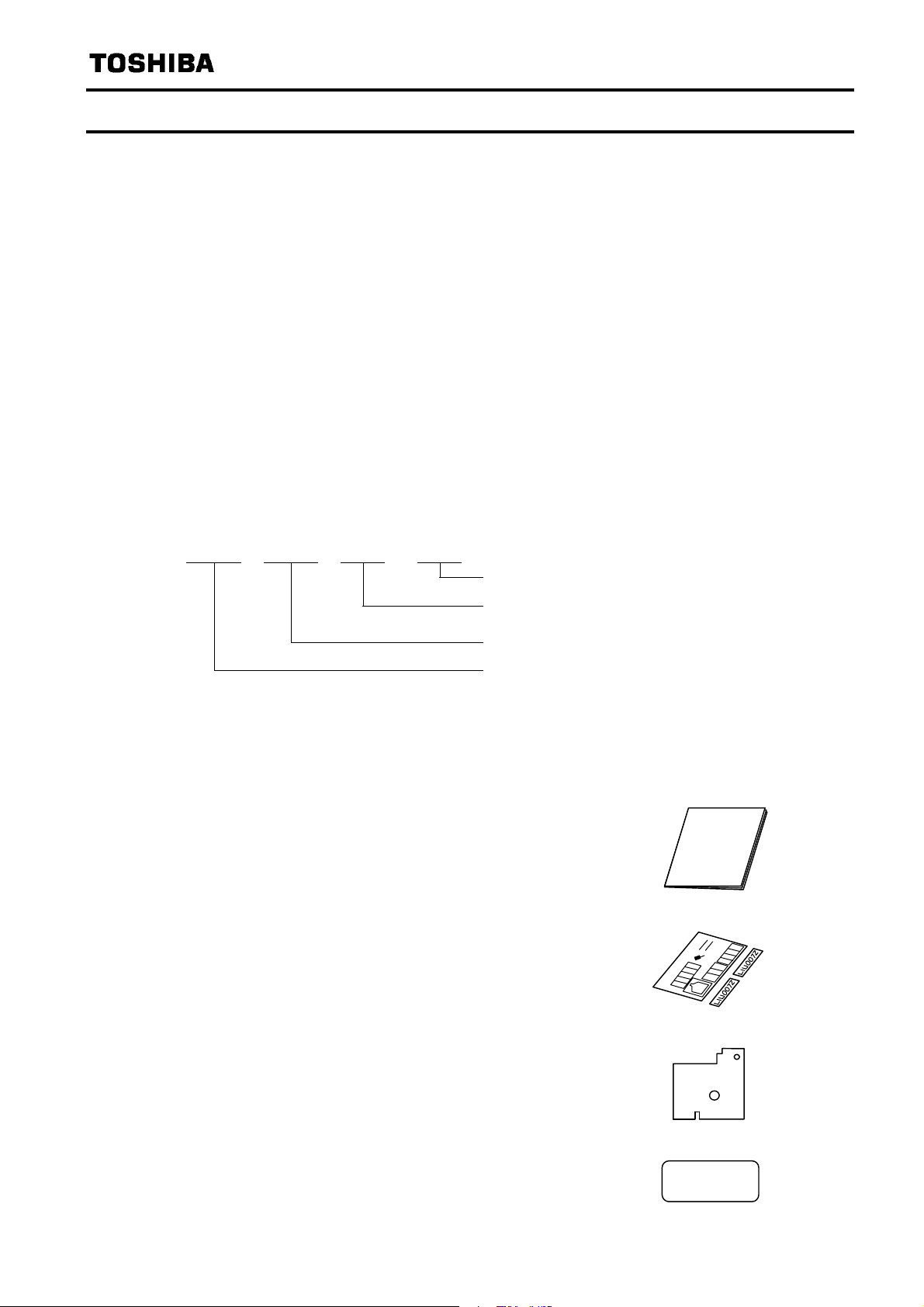
- Part numbering
LIU 007 Z
0
–
Revision number
Cable length ( “Z” means “without cable” )
Model number of LONWORKS option
Symbol of LONWORKS option
- Accessory check list
L
ONWORKS communication option is shipped together with the following accessories. On
opening the packing case, check to see if the following accessories are contained or not.
(1) Instruction manual
English (E6581371) ......................................1 copy (This book)
Instruction
Manual
(2) Cabling label & Name plate ............................1 sheet.
(1 cabling label and 2 name plates)
(3) Insulating sheet...............................................1 sheet.
(4) Neuron ID Label..............................................4 sheets.
(These are stuck on the unit)
- 4 -
||||||||||||||||||||
xxxxxxxxxx
Page 6

E6581371c
Table of Contents
1. Overview ・・・・・・・・・・・・・・・・・・・・・・・・・・・・・・・・・・・・・・・・・・・・・・・・・・・・・・・・・・・・・・・・・・・・・・・・ 6
2. Names and functions・・・・・・・・・・・・・・・・・・・・・・・・・・・・・・・・・・・・・・・・・・・・・・・・・・・・・・・・・・・・・・ 6
2.1. Service pin ・・・・・・・・・・・・・・・・・・・・・・・・・・・・・・・・・・・・・・・・・・・・・・・・・・・・・・・・・・・・・・・・・・ 6
2.2. Use of RS485 communication port ・・・・・・・・・・・・・・・・・・・・・・・・・・・・・・・・・・・・・・・・・・・・・ 6
2.3. Description of terminals ・・・・・・・・・・・・・・・・・・・・・・・・・・・・・・・・・・・・・・・・・・・・・・・・・・・・・・・ 7
3. Installation and Setup ・・・・・・・・・・・・・・・・・・・・・・・・・・・・・・・・・・・・・・・・・・・・・・・・・・・・・・・・・・・・・ 8
3.1. Installation method ・・・・・・・・・・・・・・・・・・・・・・・・・・・・・・・・・・・・・・・・・・・・・・・・・・・・・・・・・・・ 8
3.2. VF-FS1 communication parameters ・・・・・・・・・・・・・・・・・・・・・・・・・・・・・・・・・・・・・・・・・・・・ 9
3.3. Network cable connection ・・・・・・・・・・・・・・・・・・・・・・・・・・・・・・・・・・・・・・・・・・・・・・・・・・・・・ 9
3.4. Network configuration・・・・・・・・・・・・・・・・・・・・・・・・・・・・・・・・・・・・・・・・・・・・・・・・・・・・・・・・ 10
3.5. Termination resistor ・・・・・・・・・・・・・・・・・・・・・・・・・・・・・・・・・・・・・・・・・・・・・・・・・・・・・・・・・ 11
3.6. Wiring of a control terminal ・・・・・・・・・・・・・・・・・・・・・・・・・・・・・・・・・・・・・・・・・・・・・・・・・・・ 11
4. Before making a service call ・・・・・・・・・・・・・・・・・・・・・・・・・・・・・・・・・・・・・・・・・・・・・・・・・・・・・・ 12
4.1. Display of service LED ・・・・・・・・・・・・・・・・・・・・・・・・・・・・・・・・・・・・・・・・・・・・・・・・・・・・・・・ 12
4.2. Other problems ・・・・・・・・・・・・・・・・・・・・・・・・・・・・・・・・・・・・・・・・・・・・・・・・・・・・・・・・・・・・・ 12
5. Specifications ・・・・・・・・・・・・・・・・・・・・・・・・・・・・・・・・・・・・・・・・・・・・・・・・・・・・・・・・・・・・・・・・・・・ 13
6. Warranty ・・・・・・・・・・・・・・・・・・・・・・・・・・・・・・・・・・・・・・・・・・・・・・・・・・・・・・・・・・・・・・・・・・・・・・・ 14
- 5 -
Page 7

E6581371c
1. Overview
LONWORKS technology is a network control system concept developed by Echelon Corporation,
ONWORKS network provides Local Operating Network that is superior in the distributed control.
L
Each device works in a peer-to-peer fashion on LONWORKS network. This LONWORKS option is
equipped with the L
ONWORKS Smart Transceiver (Neuron Chip).
2. Names and functions
The drawing below shows names and functions of main parts.
Selector switch (SW1)
- Logic for F, R terminal
(SINK/SOURCE)
- VIB function
(VIB/PTC)
Optional RS485 communication port
RS485 communication option can be
used. However it makes L
Communication be disabled.
ONWORKS
NETA
SHLD
G/E
FLA
FLB
LONWORKS network detachable terminal
NETB
2.1. Service pin
Service pin is used for commissioning device. Use SW2 on the option board.
Danger
Service pin (SW2)
Service LED
Terminal board fixing
screw hole
(M3 screw)
FLC
Operate Service switch only when a cover for the main circuit terminal is attached.
Otherwise, it may lead to electric shocks.
Mandatory
Operate Service switch using the non-conductive stick. When it is operated with a
conductive stick.
Otherwise, it may lead to electric shocks.
2.2. Use of RS485 communication port
Serial communication (2-wire RS485) option can be used. However, while it is connected, the
internal communication line is switched to RS485 then the communication via L
is disabled. In this case, communication error trip time (f803) is also active. Use RS485 serial
communication option specified by Toshiba.
- 6 -
ONWORKS network
Page 8

2.3. Description of terminals
<Control terminals specification>
E6581371c
Terminal
symbol
NETA
NETB
SHLD
ONWORKS
L
data / reception data
ONWORKS
L
shield terminal.
Function Electrical specifications Internal circuits
transmission
communication
no polarity
This terminal is not
connected to other circuits in
this board.
G/E Grounding terminal Connect to network ground
F
R
VIB
Multifunctional programmable
contact input.
SINK/SOURCE can be
selected with SW1.
Multifunction programmable
analog input.
with internal pull-up resistor
for PTC
No voltage contact input
, 5mA or less
24V
DC
N.B. Use contact parts for low
current.
0 to 10V
DC
input
Using this terminal as PTC
input, set SW1 to PTC side
and set the parameters
(f645 and f646) to
proper value.
CC
Control circuit’s equipotential
terminal
P24 24 VDC power supply output 24VDC-50mA
P24
F, R
CC
NETA
NETB
SHLD
VIB
G/E
P24
PTC
4.7k
PTC
Spark
gap
P24
820
PTC
FT-X1
SOURCESINK
15k
15k
P10
VIB
3.3k
P24
FLA
FLB
FLC
Prohibited
Mandatory
FLA
FLB
FLC
Multifunctional programmable
relay contact outputs
1c contact
-0.5A
30V
DC
250V
250V
-1A (cosφ =1)
AC
-0.5A (cosφ =0.4)
AC
Danger
Do not change switches settings while the power is on.
It may lead to electric shocks or damage.
Turn off the motor operation signals before setting the parameter and the switch
(SW1), when changing the VIB function. Otherwise, the motor may suddenly
start and that may result in injuries.
- 7 -
Ry
Page 9

E6581371c
(
)
3. Installation and Setup
3.1. Installation method
Install the LONWORKS communication option to VF-FS1 as follows.
(1) Turn off the input power of VF-FS1 and wait for at least 10 minutes and then check that the
CHARGE lamp on VF-FS1 is no longer lit.
(2) Open the VF-FS1 front cover, remove the terminal board fixing screw and take off the VF-FS1
standard terminal board.
(Be careful not to lose the terminal board fixing screw when removed since it may be used again.)
(3) Perform wiring an inverter before installing L
(4) Please attach the insulating sheet in VF-FS1.
(Fix to the terminal board fixing screw hole and PWB catch pin.)
(5) Install the L
ONWORKS communication option over the insulating sheet and secure it with the
board fixing screw (tightening torque of M3 tapping screw: 0.7 to 0.8Nm).
(6) Stick the cabling label for L
ONWORKS communication option on the standard cabling label stuck
on the reverse side of the VF-FS1 front cover. And stick the L
nameplate near the standard nameplate. (Be careful not to cover slits on the VF-FS1 enclosure.
N.B.: To install or remove the terminal board, make it slide in or out in parallel with board.
ONWORKS communication option.
ONWORKS communication option
Cabling label position
Example
VF-FS1 unit
Board catching pin
Terminal board fixing screw
(M3 screw tightening torque: 0.7 to 0.8Nm)
Board fixing screw hole
Stick the LIU007Z nameplate like
bellow figure.
LIU007Z
VF-FS1 name plate
LIU007Z
VF-FS1 Standard terminal board
Insulating seat
(attached)
LONWORKS communication option
LIU007Z
- 8 -
Page 10

E6581371c
A
3.2. VF-FS1 communication parameters
Set up the inverter parameters as follows. To update, reset the power of inverter. If these
parameters are not set to correct value, this unit can not work normally.
Title Function Description
cmod Command mode selection
fmod Setpoint mode selection
f800 Communication speed Set “1: 19200bps” (default).
f801 Parity Set “1: Even” (default).
f803 Communication error trip time Set communication time out period.
f829 Communication protocol Set “1: MODBUS-RTU”
f851 Operation at network error
While L
into VF-FS1, The network command and setpoint are
prior to cmod/fmod. VF-FS1 front panel operation
is prior when LOC lamp on the front panel turns on.
Set the behavior when “Receive heart beat timer”
overflow occurred.
ONWORKS communication option is installed
Warning
Set up “Communication error trip function (f803, see the inverter instruction
manual for details)” to stop the inverter when this option unit is deactivated by an
unusual event such as tripping, an operating error, power outage, failure, etc.
Mandatory
Deactivated option unit may cause an accident, if the “Communication error trip
function” is not properly set up.
3.3. Network cable connection
Connect the LONWORKS network cable to LONWORKS communication option as follows.
(1) Cable selection (a twisted pair cable with shield)
Use Level 4/22 AWG cable for the network cable.
- Recommended cable
Manufacturer: Showa Electric Wire & Cable Co., Ltd.
Model name: LW221S, 22AWG, 1P, With shield, Standard 300m/reel
Use 0.75mm
(2) Terminal blocks
Catches
- Communication terminal NETA, NETB
Connect L
Polarity of the communication terminals NETA and NETB does not have to be considered.
- Communication shield terminal SHLD
Connect the shield of network cable. Refer to next section for grounding.
- G/E terminal
Connect the network ground.
(3) Connection
Cable sheath should be peeled off by about 7mm.
For wiring work, use a flat blade screwdriver with a 0.6mm thick and 3.5mm width blade.
Tightening torque for the terminal block is 0.5Nm.
2
wire for grounding to the earth terminal (G/E) of the board.
Manufacturer: PHOENIX CONTACT
Model name: MSTB 2,5/3-ST-5.08
SHLD
NET
ONWORKS
NETB
transmission/reception data cable.
- 9 -
Page 11

3.4. Network configuration
A
A
A
Make up the network as follows.
- Transmission/reception signals (NETA, NETB)
Make up the communication path by connecting all transmission/reception data cables (No polarity).
- Grounding the shield of cable (SHLD)
Connect the all shield lines of network cable. Ground through a metal film resistor of 470k ohm,
1/4W, 10% or more accurate so that static electricity does not increase (at the point where it
separated from the power ground of inverters or motors).
- Termination resistor (Please refer to “3.5. Termination resistor”)
Only one terminal resistor is needed for the segment of the free topology. It can also be placed
wherever it is on the free topology segments. (2 termination resistors in case of Bus topology)
- Network cable length (for recommended cable usage)
Free-Topology: device-to-device distance is 400m or less, total wire length is 500m or less
Bus-Topology: total wire length is 1400m or less, stub length is 3m or less.
E6581371c
- Connection image
Host computer
/ Router
Terminal 1
Terminal 2
Shield grounding
resistor
Twisted pair cable with shield
LIU007Z
NET
NETB
SHLD
LIU007Z
NET
NETB
SHLD
LIU007Z
NET
NETB
SHLD
Terminal resistor
52.3ohm, 1/8W
Network configuration is shown in the figures below. This LONWORKS communication option has
TP/FT-10 channel type transceiver. The free topology wiring supported by the TP/FT-10 channel
type accommodates bus, star, loop, or several combinations of these topologies shown in below
- Network configuration example
Host computer
Router
LIU007Z
VF-FS1
Number of connected units to the router: 63 nodes at maximum
Free topology: 63 units connected at maximum
Router Router
LIU007Z
VF-FS1
- The free topology wiring example.
Complex topology can be configured
Termination
resistor
means a node
N.B.: Do not connect the SHLD terminal to the power ground of inverters or other units.
Keep the network cables 20cm or more separate from the power cables to prevent from
malfunctioning due to electromagnetic noise.
- 10 -
Page 12

E6581371c
r
3.5. Termination resistor
Terminate the network bus with about 52.3ohm impedance to minimize the reflections. There are
two choices for the termination.
1. Free Topology Network Segment
Only one termination and may be placed anywhere on the free topology segment.
RC network (Following figure), with R1 = 52.3ohm +/-1%, 1/8W
2. Doubly Terminated Bus Topology Segment.
It is necessary to terminate at both ends of a twisted pair bus.
RC network (Following figure), with R1 = 105ohm +/-1%, 1/8W
Terminal circuit
R1
C1
C2
+
+
C1 and C2 are required for connection to link power network.
C1, C2: Aluminum-electrolytic type
100uF, 50V min
3.6. Wiring of a control terminal
Observe the following when wiring.
2
- Use 0.3 to 1.5mm
- Remove the sheath of a cable about 7mm (6mm for FLA, FLB, FLC and G/E) from the end of cable.
- Use a flat-headed screwdriver with its blade 0.6mm in thickness and 3.5mm in width.
- Screw tightening torque for the terminal block screws should be 0.5 to 0.6Nm.
N.B.: Keep the control signal cables 20cm or more separate from the power cables to prevent from
malfunctioning due to electromagnetic noise.
N.B.: Provide an inter-lock system stated in below, when using a programmable controller that has
the open collector output.
When the programmable controller is turned off with the inverter is on, the difference
between each control power potential will cause wrong signals to the inverter as shown in
below figure. Provide an inter-lock so that the programmable controller cannot be turned off
when the inverter power is alive.
solid/stranded wire (AWG 22 to 16) for control cables.
VF-FS1 + LIU007ZProgrammable controller
+24V
Input terminal
External
Fuse blowout
detection
circuit
Fuse
+24V supply
Inverte
internal +24V
COM
- 11 -
Page 13

E6581371c
4. Before making a service call
If a problem arises, please see the following trouble-shooting tables. If the problem can not be
solved, please contact a Toshiba distributor.
4.1. Display of service LED
Service LED indicates the condition of nodes.
1
2
3
4
5
6
Power
ON
No Phenomenon
Although the inverter is turned
1
on, LED remains OFF.
LED continues to be ON after
2
the inverter is turned on.
LED is ON then OFF when
3
the inverter is turned on, and
it continues to be ON.
4 LED blinks every 0.5 second.
5 LED blinks every 1 second.
LED momentarily turns ON
6
then continues to be OFF.
1 3452
Continues to be OFF
Continues to be ON
Momentarily OFF then continues to be ON
Repeats ON and OFF
Repeats ON and OFF
Continues to be OFF
Time (second)
OFFON
Problem & Solutions
Check the connection the inverter and the optional unit. If
abnormality is not found after checking, it needs to be repaired.
Internal application program is abnormal.
It needs to be repaired.
A watch dog is suspected. If the same indication appears after
resetting the power, it needs to be repaired.
This is a normal action of the "Unconfigured" device. If the device
is not "Unconfigured", Internal application program is broken. It
needs to be repaired.
When the program is in the condition of "Configured" status, LED
momentarily turns ON when the inverter is turned on. Then the
LED continues to be OFF for some seconds. The node indicates
"Configured" status that means the normal condition.
- LED Flickers CPU is abnormal. It needs to be repaired.
LED is turned on while
-
pushing service pin.
4.2. Other problems
Phenomenon
No replying from LONWORKS
communication option
Communication error
in network variable
Normal operation while pushing service pin.
Problem and Solutions
Check proper termination resister is installed on the network.
(See section 3.5.)
After checking the service LED status, see the previous section.
Remove RS485 communication option from RJ45.
Check the inverter parameter setting (refer to section 3.2).
Check the network cables are not near the power cables.
- 12 -
Page 14

5. Specifications
A
< Environmental specification >
Item Specification
Service environment Conforms to VF-FS1
Operation temperature Conforms to VF-FS1
Storage temperature
Relative humidity 20 to 93% (free from condensation and vapor)
Vibration 5.9m/s2 (0.6G) or less (10 to 55 Hz) (To be complied with JIS C0040.)
< LONWORKS communication option (LIU007Z) side >
Item Specification Note
Applicable
Commun
ication
between
inverter
model
Communication
method
Baud rate 19200bps
Parity Even number
Control power supply 5 V
Logic input terminal
Logic output terminal Nothing
Relay contact output
terminal
Analog input terminals 1 circuit (VIB): 10VDC (R
Analog output terminals Nothing
Power supply output 24VDC-50mA Current limit function
-25 to +65℃
VF-FS1
MODBUS-RTU
DC
2 circuits (F,R)
Slide switch (SW1) enable to select
logical configurations (Source/Sink).
250V
250V
-0.5A
DC
-1A (cosφ =1)
AC
-0.5A (cosφ =0.4)
C
= 30kohm) Not isolated
IN
1 circuit (FL): 30V
Only one board connection is
available.
Set the inverter parameter
(refer to section 3.2)
Supplied from inverter
Not isolated
Isolated
E6581371c
< Network side >
Item Specification Notes
Transceiver
Channel type
TP/FT-10 type
(Free topology transceiver
78kbps
ANSI/EIA/CEA 709.3
Communication signal 2 wires plus shield NETA, SHLD, NETB
Transmission distance
(Free topology)
Transmission distance
(Bus topology)
Number of connected
nodes
Between devices: 400m at maximum
Total cable length: 500m at maximum
Total cable length: 1400m at maximum
Stub length: 3m at maximum
Free topology 63 nodes at maximum
When recommended cable is used:
Level 4/22AWG
When recommended cable is used:
Level 4/22AWG
Because a host and routers are
counted as one board, the option can
be connected up to 63 nodes.
Protocol LonTalk ANSI/EIA 709.1
Address and related
items
Network variables
Service pin Mechanical switch (SW2)
Number of domains: 2
Number of address entries: 37
Number of alias tables: 8
Number of transmission data: 17
Number of receiving data: 8
Number of configuration property: 12
ONMARK Variable Speed Motor Drive
L
functional profile.
Used for notification of Neuron ID to
the host.
Applicable terminal block
Terminal block Detachable terminal block 3-pole
Manufacturer: PHOENIX CONTACT
Type-Form : MSTB 2,5/3-ST-5.08
- 13 -
Page 15

E6581371c
6. Warranty
Any part of LONWORKS communication option that is proved to be defective will be repaired free of
charge under the following conditions:
1. This product will be repaired free of charge, if problem/fault occurs under normal handling
within one year of delivery and is caused obviously by a design or manufacturing defect.
2. The warranty applies only to the delivered product.
3. For the following kinds of failure or damage, the repair cost shall be borne by the customer
even within the warranty period.
i) Failure or damage caused by improper or incorrect use or handling, or unauthorized repair
or modification of the inverter.
ii) Failure or damage caused by the unit falling or an accident during transportation after the
purchase.
iii) Failure or damage caused by fire, salty water or wind, corrosive gas, earthquake, storm or
flood, lightning, abnormal voltage supply, or other natural disasters.
iv) Damage due to the use of L
4. If an additional warranty is provided then those conditions will also apply.
ONWORKS communication option for non-intended purposes.
- 14E -
Page 16

 Loading...