

Toshiba 57HX93, 65HX93 Owner's Manual
51HX93
57HX93
65HX93
23566005
Projection Television
OWNER'S MANUAL
Owner’s Record
The model number and serial number are on the back
of your TV. Record these numbers in the spaces below.
Refer to these numbers whenever you communicate
with your Toshiba dealer about this TV.
Model number:
Serial number:
I
S
O
1
4
0
0
1
F
I
L
E
N
o
.
A
9
6
4
5
T
O
S
H
I
B
A
A
M
E
R
I
C
A
C
O
N
S
U
M
E
R
P
R
O
D
U
C
T
S
,
I
N
C
.
For an overview of steps for
installing, setting up, and using
your new TV, see page 8.
2
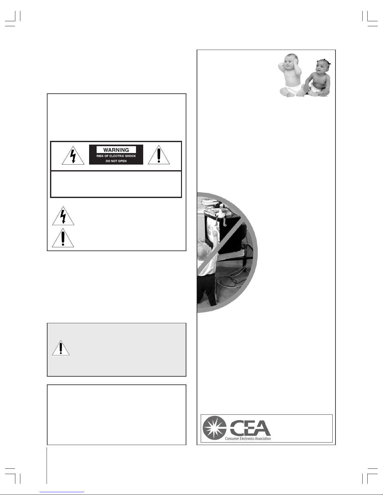
Child Safety
It Makes A Difference
Where Your TV Stands
Congratulations on your purchase! As you enjoy
your new TV, keep these safety tips in mind:
The Issue
If you are like most consumers, you have a TV in your home.
Many homes, in fact, have more than one TV.
The home theater entertainment experience is a growing
trend, and larger TVs are popular purchases; however, they
are not always supported on the proper TV stands.
Sometimes TVs are improperly secured or inappropriately
situated on dressers, bookcases, shelves, desks, audio
speakers, chests, or carts. As a result, TVs may fall over,
causing unnecessary injury.
Toshiba Cares!
The consumer electronics industry
is committed to making home
entertainment enjoyable and safe.
The Consumer Electronics
Association formed the Home
Entertainment Support Safety
Committee, comprised of TV and
consumer electronics furniture
manufacturers, to advocate
children’s safety and educate
consumers and their families about
television safety.
Tune Into Safety
One size does NOT fit all! Use appropriate
furniture large enough to support the weight of your
TV (and other electronic components).
Use appropriate angle braces, straps, and anchors to secure
your furniture to the wall (but never screw anything directly
into the TV).
Carefully read and understand the other enclosed
instructions for proper use of this product.
Do not allow children to climb on or play with furniture
and TVs.
Avoid placing any item on top of your TV (such as a VCR,
remote control, or toy) that a curious child may reach for.
Remember that children can become excited while watching
a program and can potentially push or pull a TV over.
Share our safety message about this hidden hazard of
the
home with your family and friends. Thank you!
2500 Wilson Blvd.
Arlington, VA 22201 U.S.A.
Tel. 703-907-7600 Fax 703-907-7690
www.CE.org
CEA is the Sponsor, Producer and
Manager of the International CES
®
Safety Precautions
WARNING
TO REDUCE THE RISK OF FIRE OR ELECTRIC SHOCK,
DO NOT EXPOSE THIS APPLIANCE TO RAIN OR
MOISTURE.
Dear Customer,
Thank you for purchasing this Toshiba TV. This manual will
help you use the many exciting features of your new TV.
Before operating the TV, please read this manual
completely, and keep it nearby for future reference.
NOTE TO CATV INSTALLERS IN THE USA
This is a reminder to call the CATV system installer’s
attention to Article 820-40 of the NEC, which provides
guidelines for proper grounding and, in particular, specifies
that the cable ground shall be connected to the grounding
system of the building, as close to the point of cable entry
as practical. For additional antenna grounding information,
see items 25 and 26 on page 4.
The lightning symbol in the triangle tells you that the
voltage inside this product may be strong enough to
cause an electric shock. DO NOT TRY TO SERVICE
THIS PRODUCT YOURSELF.
The exclamation mark in the triangle tells you that
important operating and maintenance instructions
follow this symbol.
WARNING: TO REDUCE THE RISK OF ELECTRIC
SHOCK, DO NOT REMOVE COVER (OR BACK).
NO USER-SERVICEABLE PARTS INSIDE. REFER
SERVICING TO QUALIFIED SERVICE PERSONNEL.
NOTICE OF POSSIBLE TV STAND INSTABILITY
DANG ER: RISK OF SERIOUS PERSONAL
INJURY OR DEATH!
Use this TV with
the TOSHIBA TV stand recommended in the
“Specifications” section only.
Use with other stands may
result in instability, causing possible injury or death.
NOTICE OF POSSIBLE ADVERSE EFFECTS
ON TV PICTURE TUBE
If a fixed (non-moving) pattern remains on the TV
screen for long periods of time, the image can become
permanently engrained in the picture tube. This type of
damage is NOT COVERED BY YOUR WARRANTY.
See item 33 on page 4.
0303
3
Installation, Care, and Service
Installation
Follow these recommendations and precautions and heed all
warnings when installing your TV:
16) Never modify this equipment. Changes or modifications
may void: a) the warranty, and b) the user’s authority to
operate this equipment under the rules of the Federal
Communications Commission.
17) DANG ER: RISK OF SERIOUS PERSONAL
INJURY, DEATH, OR EQUIPM ENT
DAMAGE! Never place the TV on
an unstable cart, stand, or table. The TV
may fall, causing serious personal injury,
death, or serious damage to the TV.
18) Never place or store the TV in direct
sunlight; hot, humid areas; areas
subject to excessive dust or vibration;
or locations with temperatures at or
below 41°F (5°C).
19) Always place the TV on the floor
or a sturdy, level, stable surface that
can support the weight of the unit.
20) Never place items such as vases,
aquariums, or candles on top of the TV.
21) Never block or cover the slots or
openings in the TV cabinet back,
bottom, and sides. Never place
the TV:
• on a bed, sofa, rug, or similar
surface;
• too close to drapes, curtains,
or walls; or
• in a confined space such as a
bookcase, built-in cabinet, or any
other place with poor ventilation.
The slots and openings are provided
to protect the TV from overheating
and to help maintain reliable
operation of the TV.
22) Never allow anything to rest on or roll over the power
cord, and never place the TV where the power cord is
subject to wear or abuse.
23) Never overload wall outlets and
extension cords.
Important Safety Instructions
1) Read these instructions.
2) Keep these instructions.
3) Heed all warnings.
4) Follow all instructions.
5) Do not use this apparatus near
water.
6) Clean only with a dry cloth.
7) Do not block any ventilation
openings. Install in accordance with
the manufacturer’s instructions.
8) Do not install near any heat
sources such as radiators,
heat registers, stoves, or other
apparatus (including amplifiers)
that produce heat.
9) Do not defeat the safety purpose of the polarized or
grounding type plug. A polarized plug has two blades
with one wider than the other. A grounding type plug has
two blades and a third grounding
prong. The wide blade or the third
prong are provided for your safety.
If the provided plug does not fit into
your outlet, consult an electrician
for replacement of the obsolete outlet.
10) Protect the power cord from being
walked on or pinched, particularly at
plugs, convenience receptacles, and
the point where it exits the apparatus.
11) Only use attachments/accessories specified by the
manufacturer.
12) Use only with the cart, stand, tripod,
bracket, or table specified by the
manufacturer, or sold with the
apparatus. When a cart is used, use
caution when moving the cart/apparatus
combination to avoid injury from tip-over.
13) Unplug this apparatus during
lightning storms or when
unused for long periods
of time.
14) Refer all servicing to qualified service personnel.
Servicing is required when the apparatus has been
damaged in any way, such as power supply
cord or plug is damaged, liquid has
been spilled or objects have fallen into
the apparatus, the apparatus has been
exposed to rain or moisture, does not
operate normally, or has been dropped.
15) CAUTION: To reduce the risk of electric shock, do not
use the polarized plug with an extension cord, receptacle,
or other outlet unless the blades can be inserted
completely to prevent blade exposure.
Wide plug
QUALIFIED
SERVICE
TECHNICIAN
0303
4
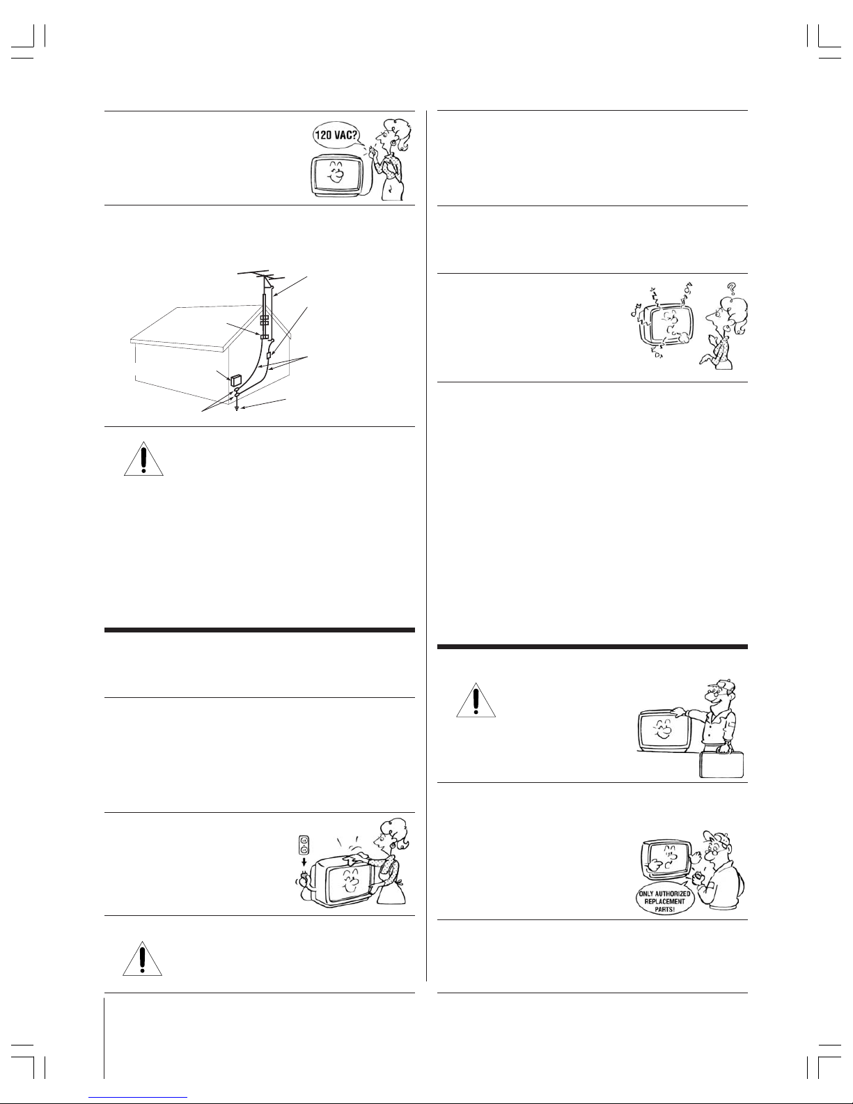
Ground clamp
Antenna discharge unit
(NEC Section 810-20)
Grounding conductors
(NEC Section 810-21)
Power service grounding
electrode system (NEC Art 250 Part H)
Ground clamps
Antenna lead-in wire
Electric service equipment
QUALIFIED
SERVICE
TECHNICIAN
24) Always operate this equipment from
a 120 VAC, 60 Hz power source only.
25) Always make sure the antenna system is properly
grounded to provide adequate protection against voltage
surges and built-up static charges (see Section 810 of the
National Electric Code).
26) DANGER: RISK OF SERIOUS PERSONAL
INJURY OR DEATH!
• Use extreme care to make sure you are never in
a position where your body (or any item you are in contact
with, such as a ladder or screwdriver) can accidentally
touch overhead power lines. Never locate the antenna
near overhead power lines or other electrical circuits.
• Never attempt to install any of the following during
lightning activity:
a) an antenna system; or b) cables, wires, or any home
theater component connected to an antenna or phone
system.
Care
For better performance and safer operation of your TOSHIBA
TV, follow these recommendations and precautions:
27) Always sit approximately 10–25 feet away from the TV and
as directly in front of it as possible. The picture can appear
dull if you sit too far to the left or right of the TV, or if
sunlight or room lights reflect on the screen. Turn the TV
off to check for reflections on the screen, and then remove
the source of reflections while viewing the TV.
28) Always unplug the TV before
cleaning. Never use liquid or
aerosol cleaners.
29) WARNING: RISK OF ELECTRIC SHOCK!
Never spill liquids or push objects of any kind
into the TV cabinet slots.
30) [This item applies to projection TVs only.] If the air
temperature rises suddenly (for example, when the TV is
first delivered), condensation may form on the lenses. This
can make the picture appear distorted or the color appear
faded. If this happens, turn off the TV for 6 to 7 hours to
allow the condensation to evaporate.
31)For added protection of your TV from lightning and power
surges, always unplug the power cord and disconnect the
antenna from the TV if you leave the TV unattended or
unused for long periods of time.
32) During normal use, the TV may make
occasional snapping or popping
sounds. This is normal, especially
when the unit is being turned on or
off. If these sounds become frequent
or continuous, unplug the power cord
and contact a Toshiba Authorized Service Center.
33) Possible Adverse Effects on TV Picture Tube: If a fixed
(non-moving) pattern remains on the TV screen for long
periods of time, the image can become permanently
engrained in the picture tube and cause subtle but
permanent ghost images. This type of damage is NOT
COVERED BY YOUR WARRANTY. Never leave your TV
on for long periods of time while it is displaying the
following formats or images:
• Fixed Images, such as PIP/POP windows, stock tickers,
video game patterns, TV station logos, and websites.
• Special Formats that do not use the entire screen. For
example, viewing letterbox style (16:9) media on a
normal (4:3) display (gray bars at top and bottom of
screen); or viewing normal style (4:3) media on a
widescreen (16:9) display (gray bars on left and right
sides of screen).
Service
34) WARNING: RISK OF ELECTRIC
SHOCK! Never attempt to service the
TV yourself. Opening and
removing the covers may expose
you to dangerous voltage or other
hazards. Refer all servicing to a
Toshiba Authorized Service Center.
35) If you have the TV serviced:
• Ask the service technician to use only replacement parts
specified by the manufacturer.
• Upon completion of service, ask
the service technician to perform
routine safety checks to determine
that the TV is in safe operating
condition.
36)When the TV reaches the end of its useful life, ask a
qualified service technician to properly dispose of the TV.
Improper disposal may result in a picture tube implosion
and possible personal injury.
0303
Copyright © 2003 TOSHIBA CORPORATION. All rights reserved.
5
Important Safety Precautions for Split Cabinet Feature
(Models 57HX93 and 65HX93 only)
Toshiba TV models 57HX93 and 65HX93 have a split
cabinet feature that allows disassembly of the cabinet into
two sections during installation.
For details, please refer to the insert titled “Disassembly/
Reassembly Instructions for Split Cabinet Feature” that
accompanied this owner’s manual in the accessory pack.
If you do not have the insert, you can download a copy of
it from our Web site (www.toshiba.com/tacp in the U.S.A.
or www.toshiba.ca in Canada). If you do not have access
to the Internet, call 1-800-631-3811 in the U.S.A. or 1-800268-3404 in Canada.
WARNING: If you split the cabinet for any
purpose, NEVER energize the bottom section
until it is completely and properly installed.
Energizing the disassembled bottom section and
subjecting it to intentional misuse (for example, exposing it to
a foreign object) creates the potential for an electrical shock
hazard that could result in death or serious injury.
CAUTION: If you use the split cabinet feature, ALWAYS
handle and treat the top section of the TV cabinet, which
contains a glass mirror, with great care. If subjected to
excessive mechanical abuse (for example, if bumped or
dropped), the mirror may break, creating exposed glass
fragments with sharp edges. Contact with these glass
fragments may result in injury.
Installation, Care, and Service
CAUTION: The split cabinet feature allows disassembly of
the cabinet into two sections during installation. If you use
the split cabinet feature, follow these precautions while
the two sections of the TV cabinet are disassembled:
1) Always handle and treat the top section of the TV cabinet
(with the viewing screen), which contains a glass mirror,
with great care. If subjected to excessive mechanical
abuse (for example, if bumped or dropped), the mirror
may break, creating exposed glass fragments with sharp
edges. Contact with these glass fragments may result in
injury.
2) Never temporarily locate the disassembled bottom section
in an area where it may be exposed to foreign objects or
abuse (for example, areas where children may be playing,
where items may fall on top of the unit, or where liquids
may spill into the unit). Failure to follow this instruction
may result in damage to the optic components of the TV.
SUCH DAMAGE IS NOT COVERED UNDER THE
TOS HIBA LIMITED WARRANTY.
3) Always keep the top and bottom sections of the TV
cabinet in an upright position while disassembled. Failure
to follow this instruction may result in damage to the TV,
including but not limited to the optic components, cabinet,
bezel, and glass mirror. SUCH DAMAGE IS NOT
COVERED UNDER THE TOSHIBA LIMITED WARRANTY.
4) Never energize the bottom section of the TV cabinet
while disassembled. Failure to follow this instruction
could result in death or serious injury.
5) Never place anything on top of the bottom section of the
TV cabinet. Failure to follow this instruction may result in
damage to the optic components. SUCH DAMAGE IS NOT
COVERED UNDER THE TOSHIBA LIMITED WARRANTY.
6) Never store or transport the unit while it is disassembled.
Failure to follow this instruction may result in damage to
the TV, including but not limited to the optic components,
cabinet, bezel, and glass mirror. SUCH DAMAGE IS NOT
COVERED UNDER THE TOSHIBA LIMITED WARRANTY.
Contents
Important Safety Information ....................................... 2-5
Chapter 1: Introduction .................................................... 7
Welcome to Toshiba....................................................... 7
Features of your new TV ................................................ 7
Note regarding the Quick Connect Guide .................. 7
Overview of steps for installing, setting up, and
using your new TV.................................................. 8
Chapter 2: Connecting your TV ...................................... 9
TV front panel controls and connections ....................... 9
TV back panel connections ............................................10
Overview of cable types ................................................. 11
About the connection illustrations ................................. 12
Connecting a VCR and antenna or Cable TV
(no Cable box) ........................................................... 12
Connecting a VCR and Cable box .................................13
Connecting a VCR and satellite receiver ........................ 14
Connecting a DVD player S-video video and a VCR ..... 15
Connecting a DVD player with component video
and a VCR ................................................................. 16
Connecting two VCRs ................................................... 17
Connecting a VCR to the REC OUT jacks ................... 17
Connecting a DVI/HDCP device .................................. 18
Connecting a camcorder ................................................ 18
Connecting a digital audio system.................................. 19
Connecting an analog audio system ............................... 19
Connecting an A/V receiver ........................................... 20
Controlling infrared remote-controlled devices
through the TV (IR pass-through) ............................. 21
Connecting IEEE-1394 (Firewire
™
) video devices ......... 22
G-LINK™ connection ..................................................25
Chapter 3: Using the remote control ............................ 26
Learning about the remote control ................................. 26
Installing the remote control batteries ............................ 27
Using the remote control MODE button to
control other devices .................................................. 27
Remote Control functional key chart .............................28
Programming the remote control to operate
your other devices ...................................................... 30
Multi-brand remote control device codes ....................... 32
Chapter 4: Menu layout and navigation ...................... 34
Main menu layout ......................................................... 34
Setup/installation menu layout ...................................... 35
Navigating the menu system .......................................... 35
(continued on next page)

Copyright © 2003 TOSHIBA CORPORATION. All rights reserved.
6
Contents (continued)
Chapter 5: Quick Connect Guide & TV Guide
On Screen™ setup ........................................................ 36
Starting the Quick Connect Guide assisted setup ........... 36
Setting up the TV Guide On Screen system ................... 37
Completing the Quick Setup Guide assisted setup .........40
Chapter 6: Setting up your TV ........................................ 41
Selecting the menu language .......................................... 41
Configuring the antenna input sources .......................... 41
Programming channels into the TV’s channel memory .. 42
Programming channels automatically ......................42
Manually adding and deleting channels in the
channel memory ................................................. 43
Programming your favorite channels .............................. 44
Setting up and using TheaterNet on-screen
device control ............................................................ 45
Setting up TheaterNet ............................................ 45
Using the TheaterNet control icons ........................ 46
TheaterNet IR device codes .................................... 47
Adjusting the color convergence..................................... 50
Setting the time and date ............................................... 51
Viewing the digital signal meter ..................................... 52
Checking system status .................................................. 52
Chapter 7: Using the TV Guide On Screen™
interactive program guide .......................................... 53
Setting up the TV Guide On Screen
™
system ................ 53
About the TV Guide On Screen
™
menus ....................... 54
Navigating the TV Guide On Screen
™
system ............... 55
LISTINGS menu ........................................................... 56
Viewing program listings and descriptions .............. 56
INFO windows ....................................................... 56
Direct tuning .......................................................... 57
Video Window ....................................................... 57
Setting programs as favorites ................................... 57
One-touch and VCR Plus+
®
recording ................... 57
Viewing panel ads and channel ads ......................... 58
Using the Menu Bar to access other menus ............. 58
SORT menu .................................................................. 58
SCHEDULE menu ....................................................... 59
Favorites schedule ................................................... 59
Record schedule ...................................................... 59
SETUP menu ................................................................ 59
Change system settings ........................................... 59
Change channel display .......................................... 59
Review options (change the auto display setting) .... 59
PROMOTIONS menu ................................................. 60
MESSAGES menu......................................................... 60
Chapter 8: Using the TV’s features ............................... 61
Selecting the video input source to view ......................... 61
Using the digital tuner hold ........................................... 61
Labeling the video input sources .................................... 62
Tuning channels............................................................. 63
Tuning to the next programmed channel ................ 63
Using SpeedSurf to change to a specific
programmed channel .......................................... 63
Tuning to a specific channel (programmed or
unprogrammed) .................................................. 63
Switching between two channels using
Channel Return .................................................. 63
Selecting the picture size ................................................ 64
Natural picture size ................................................. 65
Theater Wide 1 picture size .................................... 65
Theater Wide 2 picture size .................................... 65
Theater Wide 3 picture size .................................... 65
Full picture size ....................................................... 65
Scrolling the Theater Wide picture ................................ 66
Using the auto aspect feature (480i signals only) ............ 66
Selecting the cinema mode ............................................. 67
Selecting the display format (480p signals only) .............67
Using the POP features .................................................. 68
Using the POP double-window feature ................... 68
Switching the main and POP pictures..................... 69
Freezing the main picture in the
POP double-window .......................................... 69
Adjusting the size of the main and POP pictures..... 69
POP double-window aspect ratio ............................70
Using the programmed channel scan feature ........... 70
Using the favorite channel search feature................. 71
Adjusting the picture ..................................................... 72
Selecting the picture mode ...................................... 72
Adjusting the picture quality ................................... 72
Resetting the picture settings .................................. 72
Using the ALS (ambient light sensor)...................... 73
Using the flesh tone feature..................................... 73
Using CableClear
™
DNR (digital noise reduction) . 74
Adjusting the velocity scan modulation (VSM) .......74
Selecting the color temperature ............................... 74
Resetting the advanced picture settings ................... 74
Using the closed caption mode ...................................... 75
Advanced closed captions ........................................ 75
Adjusting the audio........................................................ 76
Muting the sound ................................................... 76
Using the sub-bass system (SBS) ............................. 76
Selecting stereo/SAP broadcasts .............................. 76
Adjusting the audio quality ..................................... 77
Using the StableSound
™
feature .............................. 77
Resetting your audio adjustments ........................... 77
Using the SRS WOW
™
surround sound feature...... 78
Resetting the advanced audio settings ..................... 78
Using the Dolby Virtual SRS TruSurround feature ...
78
Turning off the built-in speakers ............................. 79
Selecting the optical audio output format ............... 79
Selecting the AUDIO OUT sound ......................... 79
Using the SmartMedia
™
memory card picture viewer..... 80
Memory card specifications ..................................... 80
Viewing digital photos on your TV ......................... 80
Memory card care and handling.............................. 81
Setting the ON/OFF timer ............................................ 82
Setting the sleep timer.................................................... 82
Displaying TV setting information on-screen................. 83
Viewing the demo mode ................................................ 83
Understanding the auto power off feature ...................... 83
Understanding the last mode memory feature ................ 83
Chapter 9: Using the Locks menu ................................. 84
Entering the PIN code ................................................... 84
If you cannot remember your PIN code ......................... 84
Changing your PIN code ............................................... 84
Blocking TV programs and movies by rating (V-Chip) .... 85
Blocking channels .......................................................... 86
Unlocking programs temporarily ................................... 86
Locking video inputs ..................................................... 86
Using the game timer ..................................................... 87
Using the front panel lock feature .................................. 87
Chapter 10: Troubleshooting .......................................... 88
General troubleshooting ................................................ 88
TV Guide On Screen FAQs........................................... 90
Chapter 11: Appendix ...................................................... 93
Specifications ................................................................. 93
Limited United States Warranty ..................................... 94
Limited Canada Warranty .............................................. 95
Index .................................................................................... 98
Copyright © 2003 TOSHIBA CORPORATION. All rights reserved.
7
Thank you for purchasing this Toshiba TV, one of the most innovative projection TVs on the market.
The goal of this manual is to guide you through setting up and operating your TV as quickly as
possible.
• This manual applies to models 51HX93, 57HX93, and 65HX93. B efore you start reading, check
the model number on the back of your TV.
• Instructions in this manual are based on using the remote control. You also can use the controls
on the TV front panel if they have the same name as those referred to on the remote control.
• The front panel (behind the door) and back panel provide all the terminal connections you will
need to connect other equipment to your TV. See page 9 for front panel details. See page 10 for
back panel details. See pages 11–25 for instructions on connecting other devices to your TV.
• Model 57HX93 is used in this manual for illustration purposes.
• Please read all safety and operating instructions in this manual carefully, and keep this
manual for future reference.
Note regarding the
Quick Connect Guide
The Quick Connect Guide
automatically appears the first
time the TV is turned on. This
feature provides on-screen
instructions for configuring your
TV’s settings, including setting
up the TV Guide On Screen™
interactive program guide.
See page 36 for details.
To stop the Quick Connect
Guide, press EXIT or POWER.
______________
In the United States, TV GUIDE and other related marks are registered marks of Gemstar-TV Guide International, Inc. and/or one of its affiliates. In Canada, TV GUIDE is a
registered mark of Transcontinental Inc., and is used under license by Gemstar-TV Guide International, Inc. TV Guide On Screen, G-LINK, VCR Plus+ and PlusCode are
registered trademarks of Gemstar-TV Guide International and/or one of its affiliates. The TV Guide On Screen and VCR Plus+ systems are manufactured under license from
Gemstar-TV Guide International, Inc. and/or one of its affiliates.
GEMSTAR-TV GUIDE INTERNATIONAL, INC., AND/OR ITS RELATED AFFILIATES, AND/OR TOSHIBA AMERICA CONSUM ER
PRODUCTS ARE NOT IN ANY WAY LIABLE FOR THE ACCURACY OF THE PROGRAM SCHEDULE INFORMATION PROVIDED BY
THE TV GUIDE ON SCREEN SYSTEM. IN NO EVENT SHALL GEMSTAR-TV GUIDE INTE RNATIONAL, INC., AND/OR ITS RELATED
AFFILIATES, AND/OR TOSHIBA AMERICA CONSUMER PRODUCTS BE LIABLE FOR ANY AMOUNTS REPRESENTING LOSS OF
PROFITS, LOSS OF BUSINESS, OR INDIRECT, SPECIAL, OR CONSEQUENTIAL DAMAGES I N CONNECTION WITH THE
PROVISION OR USE OF ANY INFORMATION, EQUIPME NT, OR SERVICES RELATING TO THE TV GU IDE ON SCRE EN SYSTEM.
The TV Guide On Screen system is protected by one or more issued United States patents such as 6,331,877; 6,239,794; 6,154,203; 5,940,073; 4,908,713; 4,751,578;
4,706,121. The TV Guide On Screen and VCR Plus+ systems are protected by one or more issued United States patents such as 6,331,877; 6,239,794; 6,154,203; 5,940,073;
4,908,713; 4,751,578; 4,706,121; 6,466,734; 6,430,359; 6,091,882; 6,049,652; 5,335,079; 5,307,173.
A recording device is required for recording. Over-the-air or cable access to stations carrying TV Guide On Screen data is required for the TV Guide On Screen system to
operate. TV Guide On Screen data is not provided by Toshiba America Consumer Products, Inc. The provider of the data may elect to discontinue the service or it may cease
to be (or never be) available in your area. In any of these circumstances, the TV Guide On Screen feature will not function.
SRS WOW, SRS and the symbol are trademarks of SRS Labs, Inc. SRS WOW technology is incorporated under license from SRS Labs, Inc.
*Manufactured under license from Dolby Laboratories. “Dolby,” “Pro Logic,” and the double-D symbol are trademarks of Dolby Laboratories.
Features of your new TV
The following are just a few of the many exciting features of your new Toshiba widescreen projection TV:
•
Integrated digital tuning (8VSB ATSC and QAM)
eliminates the need for a separate digital converter set-top box
•
TV Guide On Screen
™
no-fee interactive program guide (page 37)
•
SD SmartMedia
™
multi-card memory card slot for viewing JPEG format photos as a “slide show” on your TV (page 80)
•
TheaterNet
™
on-screen icons for control of external
IR
and
IEEE-1394
devices (page 45)
•
Two IEEE-1394 ports (DTVLink)
for multi-device connection and control (page 24)
•
DVI/HDCP
high-definition digital device input (page 18)
•
Two sets of ColorStream® HD
high-resolution component video inputs (page 14, 16)
•
Dolby Digital*
(page 19),
Virtual Dolby Digital (SRS TruSurround)
(page 78),
SRS® WOW
(page 78), and
SBS
(page 76) audio technologies
•
Digital Audio Out
optical audio connection (page 19)
•
TouchFocus
™
automatic color convergence (page 50)
•
CrystalScan HDSC
(all-time 1080i) with user-selectable 540p
•
CableClear DNR™
(page 74)
• Multi-format, double-window
POP
features (page 68)
Introduction
1
Welcome to Toshiba
To get started, see
“Overview of steps for
installing, setting up,
and using your new TV”
on page 8.
Copyright © 2003 TOSHIBA CORPORATION. All rights reserved.
8
1. Carefully read the important safety, installation,
care, and service information on pages 2–4.
Keep this manual for future reference.
2. Do not plug in any power cords until AFTER you have
connected all cables and devices to your TV.
3. If you need to split your TV into two sections during
moving or installation, read the “Important Safety Precautions
for Split Cabinet Feature” on page 5.
4. Consider the following when selecting a location
foryour TV:
• Place the TV on the floor only.
• Place the TV in a location where light does not reflect on
the screen.
• Place the TV far enough from walls and other objects to
allow proper ventilation. Inadequate ventilation may cause
overheating, which will damage the TV. THIS TYPE OF
DAM AGE IS N OT COVERED UNDER THE TOSHIBA
WAR R ANT Y BE CA U S E IT IS A R ES ULT OF MISUSE.
• Read “Installation” on pages 3–4.
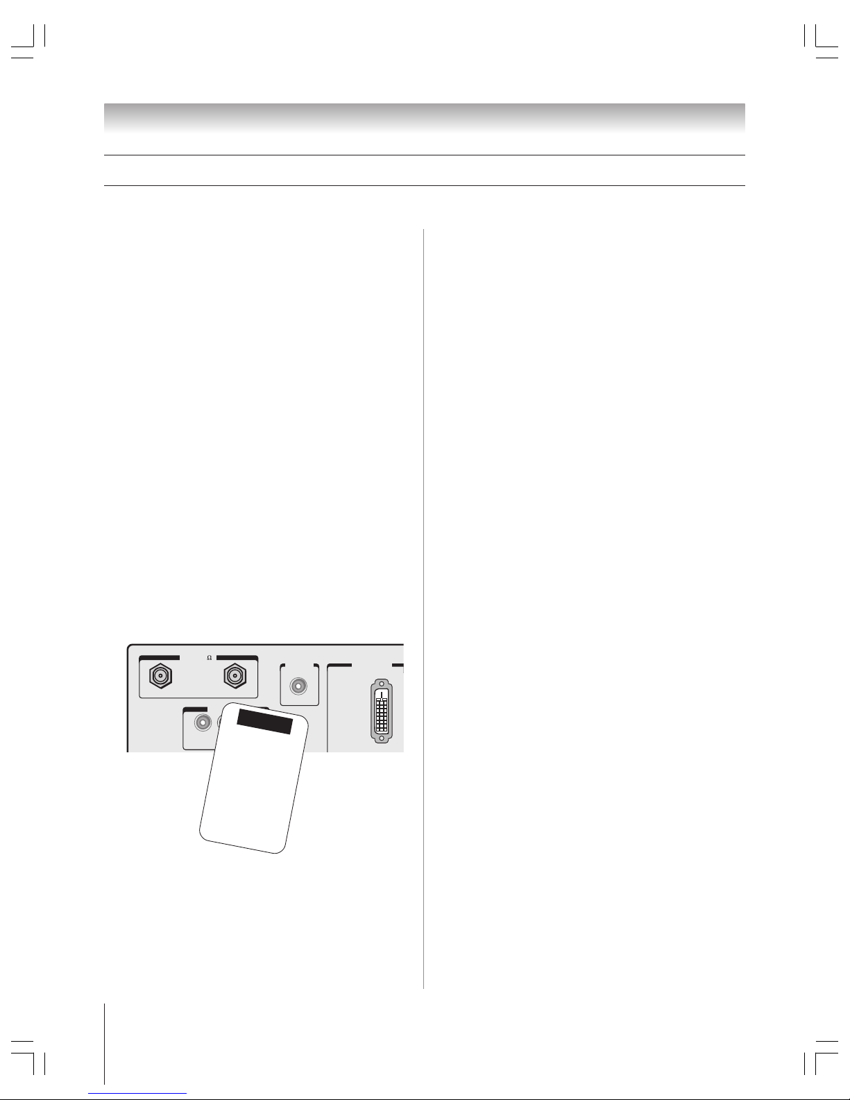
5. Remove the demo pin from the G-LINK jack on the
back of the TV (see illustration below).
8. Connect the G-LINK cable (either one of the enclosed
IR blaster cables) from your VCR and/or Cable box to the
G-LINK jack so you can use the TV Guide On Screen™ device
control and one-touch recording features. See page 25.
9. AFTER connecting all cables and devices, plug in
the power cords for your TV and other devices.
10. Install the batteries in the remote control (page 27).
11. See “Learning about the remote control” for an
overview of the buttons on the remote control
(page 26).
12. Program the remote control to operate your other
device(s) (pages 27–33).
13. Turn on the TV and other device(s).
14. Follow the on-screen Quick Connect Guide for
assistance in configuring the TV’s settings and setting up
the TV Guide On Screen™ program guide. (The Quick
Connect Guide starts automatically the first time you turn on
the TV.) See page 36 for details.
15. Program channels into the TV’s channel memory
(page 42), if you did not already do so during the Quick
Connect Guide setup.
16. See “Menu layout and navigation” for a quick
overview of the TV’s menu structure and navigation
(pages 34–35).
17. See Chapter 7 for details on using the TV Guide On
Screen™ program guide (if available in your area)
(page 53).
18. Set up the TheaterNet™ on-screen device control
feature (if applicable to your particular home theater system
components) (page 45).
19. See page 80 for details on using the
SmartMedia™/SD JPEG picture viewer.
20. See Chapter 8 for details on using the TV’s features
(page 61).
21. For technical specifications, see page 93.
22. For help, refer to the Troubleshooting Guide on
pages 88–92.
23. For warranty information, see page 94-95.
24. Enjoy your new TV!
Overview of steps for installing, setting up, and using your new TV
Follow these steps to set up your TV and begin using its many exciting features.
Chapter 1: Introduction
ANT( 75
)
REC OUT
ANT-1 ANT-2
L
AUDIO
VIDEO
R
DVI/HDCP IN
G-LINK
TV back panel
DEMO PIN
This Demo Pin
automatically activates the
TV Guide On Screen demo.
RETAILERS:
Do not remove this Demo Pin.
Removal will disable
the automatic demo.
CONSUMERS:
Remove this Demo Pin
and insert the IR blaster cable
here before using your TV.
6. BEFORE connecting cables or devices to the TV,
learn the functions of the TV’s connections and controls
(page 10).
7. Connect your other electronic device(s) to the TV
(pages 12–25).
➚
➚
Copyright © 2003 TOSHIBA CORPORATION. All rights reserved.
9
2 3 4 5 6 789 0 !¡ !™
1
{
{
{
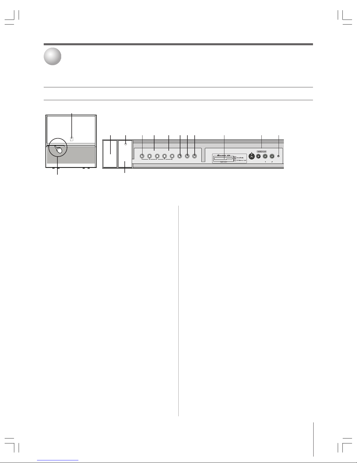
TV front panel controls and connections
1
Remote control sensor
(behind the screen)
— Point the
remote control toward this area of the TV screen.
2
POWER
— Press to turn the TV on and off.
3
Power indicator light
— When illuminated, this light
indicates that the TV is on.
4
MENU
— Press to access the menu system (see page 35).
When the TV Guide On Screen program guide is open, this
button functions as the ENTER button.
5
VOLUME
x • — When no menu is on-screen, these
buttons adjust the volume level. When a menu is on-screen,
these buttons function as left/right menu navigation
buttons.
6
CHANNEL
yz — When no menu is on-screen, these
buttons change the channel (programmed channels only).
When a menu is on-screen, these buttons function as
up/down menu navigation buttons.
7
EXIT
— Press to close an on-screen menu instantly.
8
TV/VIDEO
— Repeatedly press to change the source you are
viewing (ANT 1, ANT 2, VIDEO 1, VIDEO 2, VIDEO 3,
DVI/HDCP, ColorStream HD1, ColorStream HD2).
Press/lift to open
control panel door.
9
TouchFocus™
— Press to automatically adjust the color
convergence (see page 50).
0
SD SmartMedia™ slot
— Insert a memory card to view
JPEG files from a digital camera (see page 80).
!¡
VIDEO-3
— The front panel A/V connections are referred
to as “VIDEO 3” and include standard A/V connections
plus optional S-video. (The VIDEO 1 and VIDEO 2 A/V
connections are on the TV’s back panel. See page 10.)
!™
RESET
— If the TV stops responding to the controls on
the remote control or TV front panel and you cannot turn
off the TV, press this button to reset the TV.
Note: The RESET button is recessed, so you will need to use
the end of a paper clip or similar object to press the button.
!£
Ambient light sensor (ALS)
— The ALS detects the room’s
ambient light and automatically adjusts the contrast. If you
use the ALS feature (page 73), make sure you do not block
the ALS on the front panel or it will not work properly.
Connecting your TV
2
!£
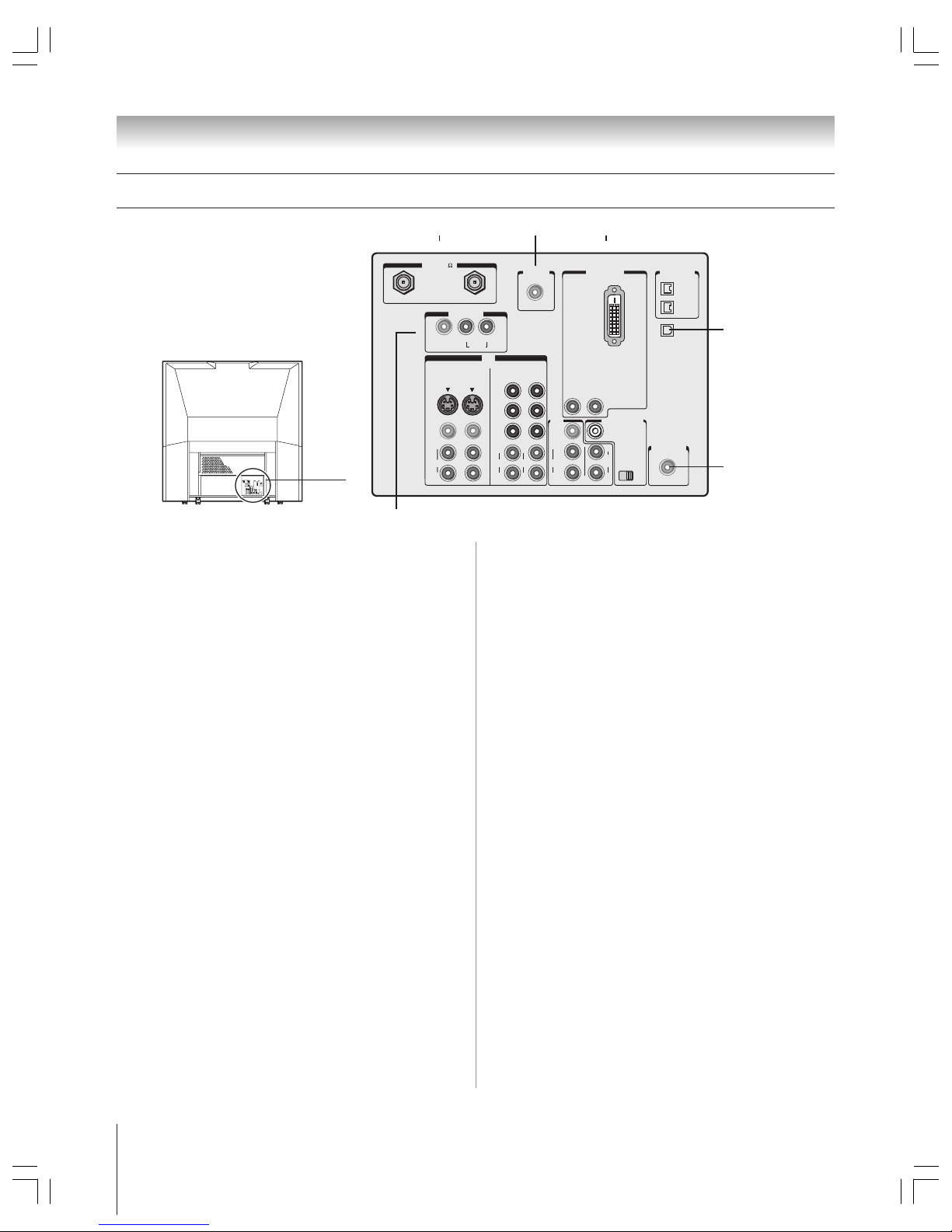
Copyright © 2003 TOSHIBA CORPORATION. All rights reserved.
10
IN
ANT( 75
)
REC OUT
ANT-1 ANT-2
PB
PR
Y
L/
MONO
AUDIO
S-VIDEO
VIDEO 1 VIDEO 2
COLOR
STREAM
HD-1
COLOR
STREAM
HD-2
VIDEO
R
L
AUDIO
VIDEO
R
L
AUDIO
R
PB
PR
Y
L
AUDIO
R
VIDEO
L/
MONO
ON OFF
L
AUDIO
AUDIO
VAR
R R
OUT
CHANNEL IN
AUDIO CENTER
DVI/HDCP IN
R
AUDIO
L
G-LINK
IR OUT
DIGITAL
AUDIO OUT
IEEE1394
1
IEEE1394
2
TheaterNet
TheaterNet
___________
Apple and FireWire are trademarks of Apple Computer, Inc., registered in the U.S. and other countries.
IN
ANT( 75
)
Rec Out
ANT-1 ANT-2
P
B
P
R
Y
L/
MONO
AUDIO
S-VIDEO
VIDEO 1
VIDEO 2
COLOR
STREAM
HD-1
COLOR
STREAM
HD-2
VIDEO
R
L/'MONO
AUDIO
VIDEO
R
L
AUDIO
R
P
B
P
R
Y
L
AUDIO
R
VIDEO
L/
MONO
ONOFF
L
AUDIO
AUDIO
VAR
R R
OUT
CHANNEL IN
AUDIO CENTER
DVI/HDCP IN
R
AUDIO
L
TheaterLink
DIGITAL
AUDIO OUT
IEEE1394
1
IEEE1394
2
TV back panel connections
For an explanation of cable types, see page 11.
4
5
789
{
{
}
{
1 ANT-1 IN and ANT-2 IN — Two inputs that support
analog (NTSC) and digital (ATSC) off-air antenna signals
and analog and digital (QAM) Cable TV signals.
Note: If you have an antenna only, connect it to ANT-1. If you have
both Cable TV and an antenna, connect the Cable TV to ANT-1 and
the antenna to ANT-2.
2 G-LINK™ — For use with one of the enclosed IR blaster/
G-LINK cables to enable the TV Guide On Screen
™
device
control and one-touch recording features. See page 25.
3 DVI/HDCP IN — Digital DVI/HDCP single-link video
plus standard audio inputs for connecting high-definition
devices with single-link DVI/HDCP output. See page 18.
Note: DVI-D cable carries only video information; separate
audio cables are required for a complete connection.
4 IEEE-1394 — Two bi-directional digital IEEE-1394 (also
known as Firewire
™
) ports for connecting multiple devices
with compressed digital video. Because these ports are
bi-directional, they can be used for playback and recording.
You can control your IEEE-1394 devices using the TV’s
TheaterNet on-screen control icons. See page 45.
Note: IEEE-1394 cable carries both audio and video information;
no separate audio cables are required for a complete connection.
5 Digital Audio OUT — Optical audio ouput in Dolby
Digital or PCM (pulse-code modulation) format for
connecting an external Dolby Digital decoder, amplifier,
AV receiver, or home theater system with optical audio
input. See page 19.
6 IR OUT — For controlling infrared remote-controlled
devices through the TV. You can connect up to two devices
with either one of the enclosed IR blaster cables, and then
control the devices using the TV’s IR pass-through or
TheaterNet
™
(on-screen device control) features. See pages
21 and 45.
7 REC (record) OUT — Composite video and audio outputs
for recording down-converted digital off-air antenna
(ATSC), digital Cable TV (QAM), or IEEE-1394 programs
to an analog VCR. See page 17.
Note: The REC OUT jacks will not output a DVI signal and
cannot be used for timed recordings.
8 VIDEO 1 IN and VIDEO 2 IN — Two sets of standard
(composite) video and standard audio inputs plus optional
S-video inputs for connecting devices with composite video
or S-video output.
Note: Standard (composite) video and S-video cables carry
only video information; separate audio cables are required for a
complete connection.
9 ColorStream HD-1 and ColorStream HD-2 — Two sets
of ColorStream
®
high-definition component video and
standard stereo audio inputs for connecting devices with
component video output, such as a Toshiba DVD player
with ColorStream.
®
See pages 14 and 16.
Note: Component video cables carry only video information;
separate audio cables are required for a complete connection.
0 A/V OUT — Standard (composite) video and standard
audio outputs for connecting a VCR for editing and
dubbing. See page 17 for details.
!¡ Variable Audio OUT — Standard audio ouputs for
connecting an analog amplifier with external speakers. See
page 19.
!™ Audio Center Channel IN plus ON/OFF switch — For
use with an external A/V receiver to enhance your TV’s
audio. When the switch is set to OFF, the TV’s audio is
output through the TV’s internal speakers. When the switch
is set to ON, the TV’s audio is output through the A/V
receiver and the TV’s speakers are used as a center channel.
See page 20.
6
1
}
2 3
}
Chapter 2: Connecting your TV
!¡
{
!º
{
!™
{
Copyright © 2003 TOSHIBA CORPORATION. All rights reserved.
11
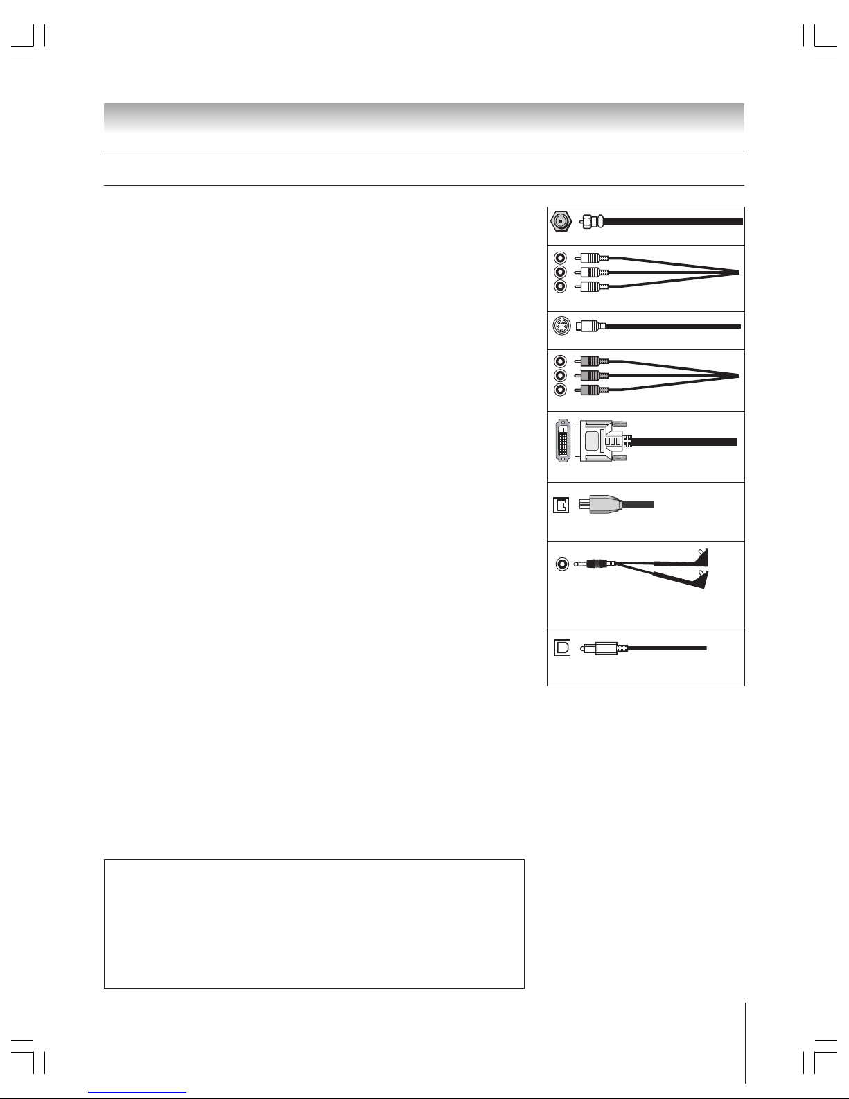
Overview of cable types
Component video cables (red/green/blue)
Coaxial (F-type) cable
Standard A/V cables (red/white/yellow)
S-video cable
CAUTION: Do not plug in any power cords
until you have finished connecting all
equipment.
DVI-D digital single-link cable
Dual-wand IR blaster/G-LINK cable
(2 included)
Note: Two dual-wand IR blaster/G-LINK cables are included with your TV. All other required
cables, if not provided with your other devices, can be purchased at many electronics
accessory suppliers.
●
Coaxial (F-type) cable is used for connecting your antenna, cable TV service,
and/or cable converter box to the ANT-1 and/or ANT-2 RF inputs on your TV.
●
Standard A/V cables (composite video) usually come in sets of three, and are for use
with video devices with standard audio and standard (composite) video output. These
cables (and the related inputs on your TV) are typically color-coded according to use:
yellow for video, red for stereo right audio, and white for stereo left (or mono) audio.
●
S-video cable is for use with video devices with S-video output. Separate audio cables
are required for a complete connection.
Note: An S-video cable provides better picture performance than a composite video cable.
If you connect an S-video cable, be sure to disconnect the standard (composite) video cable or
the picture performance will be unacceptable.
●
Component video cables come in sets of three and are for use with video devices with
component video output. These cables are typically color-coded red, green, and blue.
(ColorStream
®
is Toshiba’s brand of component video.) Separate audio cables are
required for a complete connection.
Note: Component video cables provide better picture performance than a standard (composite)
video or S-video cable.
●
DVI-D digital single-link cable is for use with video devices with uncompressed
DVI-D digital single-link output. DVI-D cable delivers digital video in its native
format (see page 18). Separate audio cables are required for a complete connection.
Note: DVI-D digital single-link cable provides better picture performance than a standard
(composite) video or S-video cable.
●
IEEE-1394 cable is for use with video devices with compressed digital video output
that meets CEA specifications for IEEE-1394 (also known as Firewire
™
). IEEE-1394
cables carry both video and audio information; therefore, no separate audio cables are
needed for a complete connection. See pages 22 and 24.
Note: IEEE-1394 cable provides better picture performance than a standard (composite) video
or S-video cable.
●
Dual-wand IR blaster/G-LINK cable is for use with video devices with IR (infrared)
remote control. Two of these cables are included with your TV. One is for connection
to the G-LINK jack (page 25) to enable TV Guide On Screen™ device control and
one-touch recording (page 53). The other can be used with the TV’s IR pass-through
feature (page 21) and TheaterNet on-screen device control feature (page 45).
Important note: The two IR blaster/G-LINK cables included with your TV have specific
characteristics that allow them to work properly with this TV’s IR OUT and G-LINK ports.
Never use other aftermarket IR blaster or G-LINK cables with this TV. Other cables
may not function properly and could cause damage. THIS TYPE OF DAMAGE IS NOT COVERED
BY YOUR TOSHIBA WARRANTY because it is a result of misuse.
●
Optical audio cable is for connecting receivers with Dolby Digital or PCM
(pulse-code modulation) optical audio input to the TV’s DIGITAL AUDIO OUT
jack. See pages 10 and 19.
IEEE-1394 cable (4-pin)
Optical audio cable
Note regarding picture quality
●
For GOOD picture quality: Use standard (composite) video cables.
●
For BETTER picture quality: If your equipment has S-video, use an S-video cable
instead of a standard (composite) video cable.
●
For BEST picture quality: If your equipment has component video (ColorStream),
DVI, or IEEE-1394 (Firewire) ouput, use component video cables, a DVI-D cable, or
an IEEE-1394 cable, respectively.
For a complete connection, be sure to connect the audio cables, where necessary.
Chapter 2: Connecting your TV
Note: Although your TV includes both
DVI/HDCP and IEEE-1394 connections,
it may not operate with another device you
have that includes such a connection. For
example, the IEE E-1394 ports are not
intended to operate with current model
Mini DV camcorders, and the DVI/HDCP
input is not intended for connection to a
computer. Copyright protection requirements
may also prohibit or limit connectivity. See
page 18 for details about the DVI/HDCP
input. See pages 22–24 for details about
the IEEE-1394 ports. You should confirm that
the devices you want to use with the TV will
operate with the appropriate connections.
Copyright © 2003 TOSHIBA CORPORATION. All rights reserved.
12
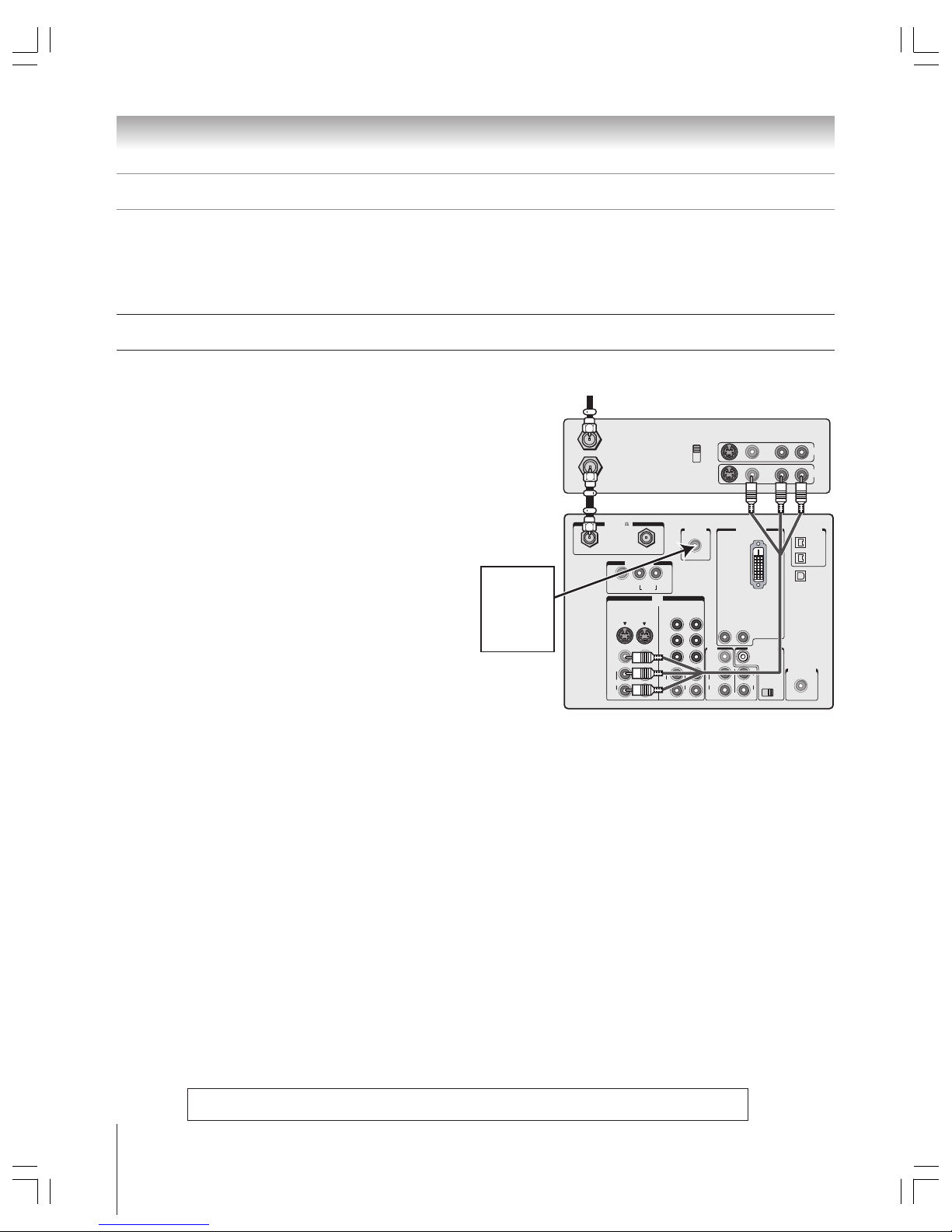
Chapter 2: Connecting your TV
IN
ANT( 75
)
REC OUT
ANT-1 ANT-2
PB
PR
Y
L/
MONO
AUDIO
S-VIDEO
VIDEO 1 VIDEO 2
COLOR
STREAM
HD-1
COLOR
STREAM
HD-2
VIDEO
R
L
AUDIO
VIDEO
R
L
AUDIO
R
PB
PR
Y
L
AUDIO
R
VIDEO
L/
MONO
ON OFF
L
AUDIO
AUDIO
VAR
R R
OUT
CHANNEL IN
AUDIO CENTER
DVI/HDCP IN
R
AUDIO
L
G-LINK
IR OUT
DIGITAL
AUDIO OUT
IEEE1394
1
IEEE1394
2
TheaterNet
TheaterNet
IN from ANT
VIDEO AUDIO
OUT to TV
CH 3
LR
LR
CH 4
IN
OUT
You will need:
two coaxial cables
one set of standard A/V cables
• For better picture performance, if your VCR has S-video, use an
S-video cable (plus the audio cables) instead of the standard video
cable. However, do not connect both types of video cables to
VIDEO 1 (or VIDEO 2) at the same time or the picture
performance will be unacceptable.
• If you have a mono VCR, connect L/MONO on the TV to your
VCR’s audio out jack using the white audio cable only.
To view the antenna or Cable signal:
Turn off the VCR.
Select the ANT 1 video input source.*
• If you have both an off-air antenna and Cable TV, connect the
antenna to ANT-2 and the Cable TV to ANT-1 (because
ANT-1 is the only source for the TV Guide On Screen
program guide).
To view the VCR:
Turn ON the VCR. Select the VIDEO 1 video input source
on the TV.*
or…Turn ON the VCR. Select the ANT 1 video input source.*
Tune the TV to channel 3 or 4 (whichever channel is vacant
in your area).
_____________
* To select the video input source, press INPUT on the remote control
(see page 61). To program the TV remote control to operate other
devices, see pages 30–33.
The unauthorized recording, use, distribution, or revision of television programs, videotapes, DVDs, and other materials is
prohibited under the Copyright Laws of the United States and other countries, and may subject you to civil and criminal liability.
Connecting a VCR and antenna or Cable TV (no Cable box)
From Cable TV or antenna
Stereo VCR
TV
About the connection illustrations
You can connect different types and brands of devices to your TV in several different configurations. The suggested connection
illustrations in this manual are representative of typical device connections only. The input/output jacks on your devices may differ
from those illustrated herein. For details about connecting and using your specific devices, refer to each device’s owner’s manual.
Connect
the G-LINK
cable to the
G-LINK jack
(see page 25)
Copyright © 2003 TOSHIBA CORPORATION. All rights reserved.
13
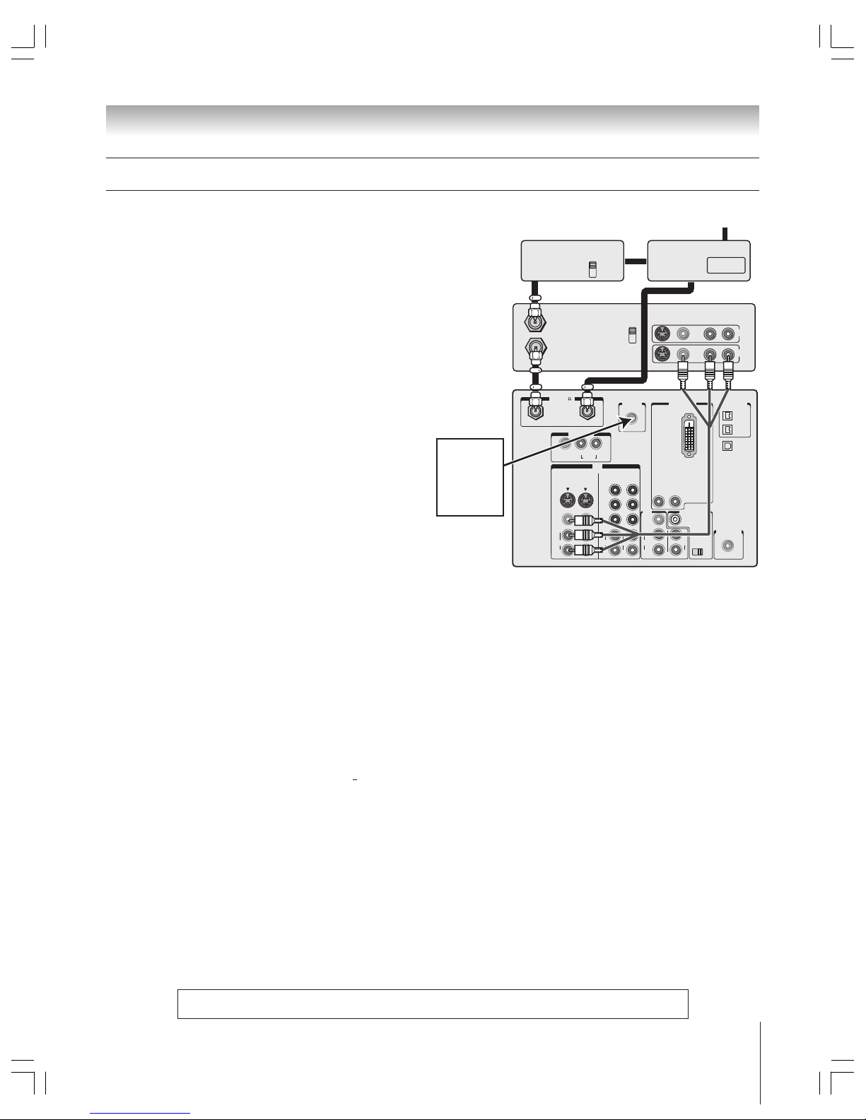
Chapter 2: Connecting your TV
IN
ANT( 75
)
REC OUT
ANT-1 ANT-2
PB
PR
Y
L/
MONO
AUDIO
S-VIDEO
VIDEO 1 VIDEO 2
COLOR
STREAM
HD-1
COLOR
STREAM
HD-2
VIDEO
R
L
AUDIO
VIDEO
R
L
AUDIO
R
PB
PR
Y
L
AUDIO
R
VIDEO
L/
MONO
ON OFF
L
AUDIO
AUDIO
VAR
R R
OUT
CHANNEL IN
AUDIO CENTER
DVI/HDCP IN
R
AUDIO
L
G-LINK
IR OUT
DIGITAL
AUDIO OUT
IEEE1394
1
IEEE1394
2
TheaterNet
TheaterNet
OUT
IN from ANT
VIDEO AUDIO
OUT to TV
CH 3
LR
LR
CH 4
IN
OUT
OUT
OUT
IN
IN
CH 3
CH 4
Cable box Cable splitter
You will need:
one Cable signal splitter
five coaxial cables
one set of standard A/V cables
• For better picture performance from your VCR: If your VCR has
S-video, connect an S-video cable (plus the audio cables) instead
of the standard video cable. Do not connect an S-video cable and a
standard video cable to VIDEO 1 (or VIDEO 2) at the same time
or the picture performance will be unacceptable.
• If you have a mono VCR, connect L/MONO on the TV to your
VCR’s audio out jack using the white audio cable only.
• For better picture performance from your Cable box: If your Cable
box has component video, you can connect component video
cables (plus the audio cables) instead of the standard video cable
from the Cable box to the ColorStream HD-1 inputs on the TV. You
would then select ColorStream HD-1 as the video input source.*
•When you use a Cable box, you may not be able to use the
remote control to program or access certain features on
the TV.
To view basic Cable channels and use the TV’s features:
Select the ANT 2 video input source.* Use the TV front
panel controls or remote control to change channels and
access the TV’s features.
To view basic and premium Cable channels:
Turn OFF the VCR. Select the ANT 1 video input source.*
Tune the TV to channel 3 or 4 (whichever channel is vacant
in your area). Use the Cable box controls to change
channels.
or…Turn ON the VCR. Tune the VCR to channel 3 or 4
(whichever channel is vacant in your area). Select the
VIDEO 1 video input source.* Use the Cable box controls
to change channels.
To view the VCR:
Select the VIDEO 1 video input source.*
Note: This will provide better picture performance if you
connected an S-video cable as mentioned in the first bulleted
item on this page.
or…Turn ON the VCR. Select the ANT 1 video input source.*
Tune the TV to channel 3 or 4 (whichever channel is vacant
in your area).
_____________
* To select the video input source, press INPUT on the remote control
(see page 61). To program the TV remote control to operate other
devices, see pages 30–33.
From Cable TV
Stereo VCR
TV
Connecting a VCR and Cable box
The unauthorized recording, use, distribution, or revision of television programs, videotapes, DVDs, and other materials is
prohibited under the Copyright Laws of the United States and other countries, and may subject you to civil and criminal liability.
Connect
the G-LINK
cable to the
G-LINK jack
(see page 25)
Copyright © 2003 TOSHIBA CORPORATION. All rights reserved.
14
Chapter 2: Connecting your TV
The unauthorized recording, use, distribution, or revision of television programs, videotapes, DVDs, and other materials is
prohibited under the Copyright Laws of the United States and other countries, and may subject you to civil and criminal liability.
Connecting a VCR and satellite receiver
You will need:
three coaxial cables
one set of component video cables (if your satellite
receiver does not have component video, connect
the standard A/V cables only)
two sets of standard A/V cables
• For better picture performance, if your satellite receiver
and VCR have S-video, connect S-video cables (plus the
audio cables) instead of the standard video cables from
the satellite receiver to the VCR and then from the VCR to
VIDEO1 on the TV. Do not connect both types of video
cable to VIDEO 1 (or VIDEO 2) at the same time or the
picture performance will be unacceptable.
• If you have a mono VCR, connect L/MONO on the TV
(VIDEO 1) to your VCR’s AUDIO OUT jack using the
white audio cable only.
To view satellite programs using the component
video connections:
Select the ColorStream HD-1 video input source on
the TV.*
To view satellite programs using the standard
video connections or to record satellite
programs:
Turn on all three devices. Select “LINE IN” on the
VCR. Select the VIDEO 1 video input source on
the TV.*
To view the VCR or view and record antenna
channels:
Select the ANT-1 video input source on the TV.*
Tune the TV to channel 3 or 4 (whichever channel
is vacant in your area).
or... Tune the VCR to the channel you want to watch.
Select the VIDEO 1 video input source on the TV.*
_____________
* To select the video input source, press INPUT on the remote
control (see page 61). To program the TV remote control to
operate other devices, see pages 30-33.
IN
ANT( 75
)
REC OUT
ANT-1 ANT-2
P
B
P
R
Y
L/
MONO
AUDIO
S-VIDEO
VIDEO 1 VIDEO 2
COLOR
STREAM
HD-1
COLOR
STREAM
HD-2
VIDEO
R
L
AUDIO
VIDEO
R
L
AUDIO
R
P
B
P
R
Y
L
AUDIO
R
VIDEO
L/
MONO
ON OFF
L
AUDIO
AUDIO
VAR
R R
OUT
CHANNEL IN
AUDIO CENTER
DVI/HDCP IN
R
AUDIO
L
G-LINK
IR OUT
DIGITAL
AUDIO OUT
IEEE1394
1
IEEE1394
2
TheaterNet
TheaterNet
S-VIDEO
OUT
VIDEO
OUT
AUDIO
OUT
COMPONENT VIDEO
LRL
R
IN from ANT
VIDEO AUDIO
OUT to TV
CH 3
L
R
L
R
LR
CH 4
IN
OUT
Satellite
IN
PBP
R
Y
From antenna
From
satellite dish
Satellite receiver
TV
Stereo VCR
Connect
the G-LINK
cable to the
G-LINK jack
(see page 25)
Copyright © 2003 TOSHIBA CORPORATION. All rights reserved.
15
Chapter 2: Connecting your TV
IN
ANT( 75
)
REC OUT
ANT-1 ANT-2
PB
PR
Y
L/
MONO
AUDIO
S-VIDEO
VIDEO 1 VIDEO 2
COLOR
STREAM
HD-1
COLOR
STREAM
HD-2
VIDEO
R
L
AUDIO
VIDEO
R
L
AUDIO
R
PB
PR
Y
L
AUDIO
R
VIDEO
L/
MONO
ON OFF
L
AUDIO
AUDIO
VAR
R R
OUT
CHANNEL IN
AUDIO CENTER
DVI/HDCP IN
R
AUDIO
L
G-LINK
IR OUT
DIGITAL
AUDIO OUT
IEEE1394
1
IEEE1394
2
TheaterNet
TheaterNet
OUT
Cable box
IN from ANT
VIDEO AUDIO
OUT to TV
CH 3
LR
LR
CH 4
IN
OUT
S-VIDEO
OUT
VIDEO
OUT
AUDIO
OUT
L
R
OUT
OUT
Cable splitter
IN
IN
CH 3
CH 4
Connecting a DVD player with S-video and a VCR
You will need:
five coaxial cables
one set of standard A/V cables
Note: If you have a mono VCR, connect L/MONO on the TV
(VIDEO 1) to your VCR’s audio out jack using the white audio
cable only.
one S-video cable
one pair of standard audio cables
Note:
• If your DVD player does not have S-video, use a standard video
cable instead. Do not connect an S-video cable and a standard
video cable to VIDEO 1 (or VIDEO 2) at the same time or the
picture performance will be unacceptable.
• If your DVD player has component video, see page 16.
• Do not connect the DVD player and VCR to the same set of
A/V inputs on the TV. (See the illustration, which shows the
VCR connected to VIDEO 1 on the TV, and the DVD player
connected to VIDEO 2.)
To view basic channels and access the TV’s features:
Select the ANT 2 video input source.* Use the TV
controls to change channels and access the TV’s features.
To view premium Cable channels:
Turn OFF the VCR. Select the ANT 1 video input source.*
Tune the TV to channel 3 or 4 (whichever channel is vacant
in your area). Use the Cable box controls to change
channels.
or…Turn ON the VCR. Tune the VCR to channel 3 or 4
(whichever channel is vacant in your area). Select the
VIDEO 1 video input source.* Use the Cable box controls
to change channels.
Note: When you use a Cable box, you may not be able to
use the remote control to program or access certain features
on the TV.
To view the DVD player:
Select the VIDEO 2 video input source.*
To view the VCR:
Select the VIDEO 1 video input source on the TV.*
or…Turn ON the VCR. Select the ANT 1 video input source.*
Tune the TV to channel 3 or 4 (whichever channel is vacant
in your area).
_____________
* To select the video input source, press INPUT on the remote control
(see page 61). To program the TV remote control to operate other
devices, see pages 30–33.
DVD player with S-video
TV
Stereo VCR
From antenna or Cable TV
The unauthorized recording, use, distribution, or revision of television programs, videotapes, DVDs, and other materials is
prohibited under the Copyright Laws of the United States and other countries, and may subject you to civil and criminal liability.
Connect
the G-LINK
cable to the
G-LINK jack
(see page 25)
Copyright © 2003 TOSHIBA CORPORATION. All rights reserved.
16
Chapter 2: Connecting your TV
IN
ANT( 75
)
REC OUT
ANT-1 ANT-2
P
B
P
R
Y
L/
MONO
AUDIO
S-VIDEO
VIDEO 1 VIDEO 2
COLOR
STREAM
HD-1
COLOR
STREAM
HD-2
VIDEO
R
L
AUDIO
VIDEO
R
L
AUDIO
R
P
B
P
R
Y
L
AUDIO
R
VIDEO
L/
MONO
ON OFF
L
AUDIO
AUDIO
VAR
R R
OUT
CHANNEL IN
AUDIO CENTER
DVI/HDCP IN
R
AUDIO
L
G-LINK
IR OUT
DIGITAL
AUDIO OUT
IEEE1394
1
IEEE1394
2
TheaterNet
TheaterNet
IN from ANT
VIDEO AUDIO
OUT to TV
CH 3
LR
LR
CH 4
IN
OUT
S-VIDEO
OUT
VIDEO
OUT
AUDIO
OUT
COMPONENT VIDEO
L
R
PBP
R
Y
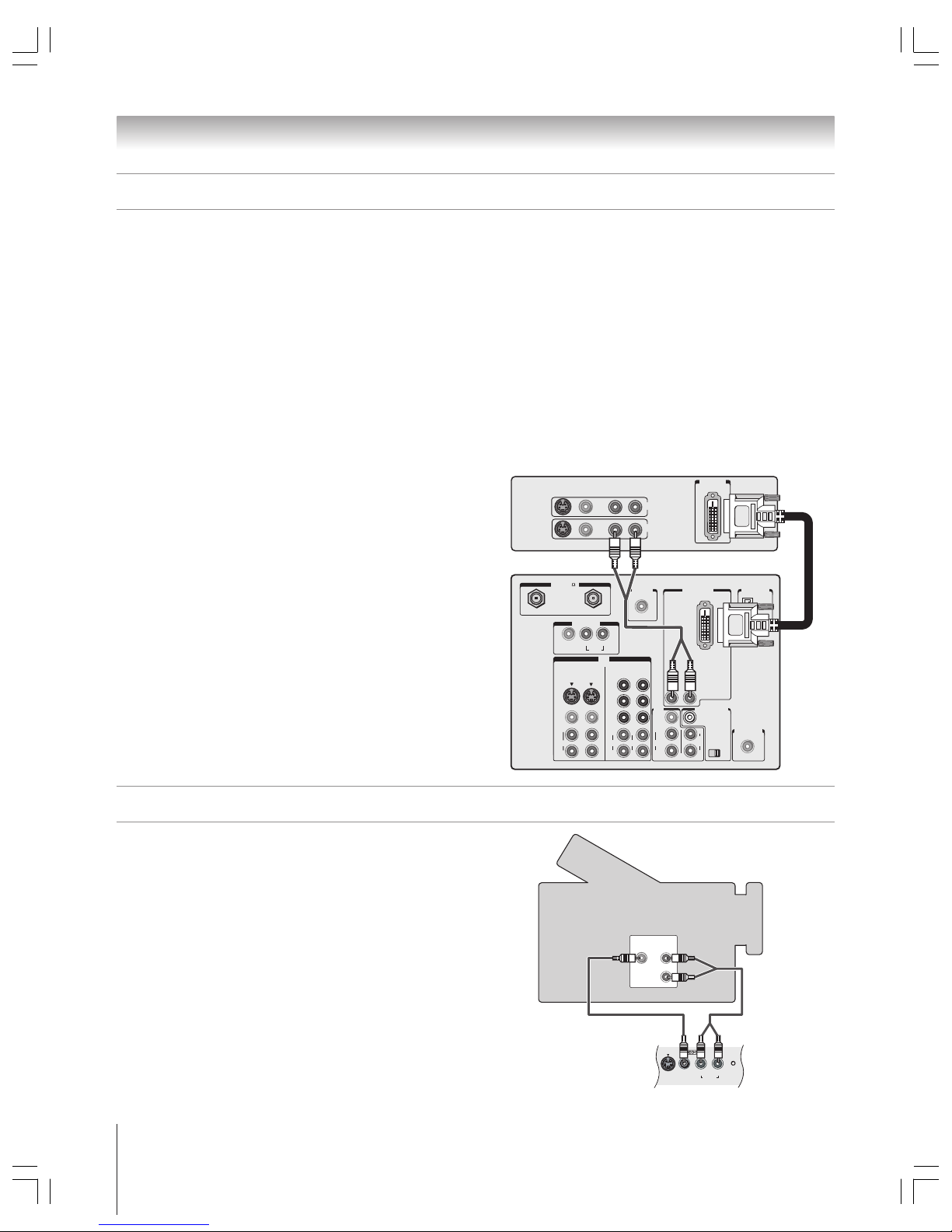
Connecting a DVD player with component video and a VCR
From antenna or Cable
Your TV has ColorStream® (component video) inputs.
Connecting a DVD player with component video output (such
as a Toshiba DVD player with ColorStream
®
) can greatly
enhance picture quality.
You will need:
two coaxial cables
two sets of standard A/V cables
• For better picture performance, if your VCR has S-video, use an
S-video cable (plus the audio cables) instead of the standard video
cable. However, do not connect both types of video cable to
VIDEO 1 (or VIDEO 2) at the same time or the picture
performance will be unacceptable.
• If you have a mono VCR, connect L/MONO on the TV (VIDEO 1)
to your VCR’s audio out jack using the white audio cable only.
one pair of standard audio cables
one set of component video cables
•You can connect the component video cables (plus audio
cables) from the DVD player to either set of ColorStream jacks
on the TV (HD-1 or HD-2). The ColorStream HD-1 and HD-2
jacks can be used with Progressive (480p, 720p) and
Interlaced (480i, 1080i) scan systems. A 1080i signal will
provide the best picture performance.
• If your DVD player does not have component video, see
page 15. If your DVD player has DVI/HDCP video, see
page 18.
To view antenna or Cable channels:
Turn OFF the VCR. Select the ANT 1 video input
source on the TV.*
To view the DVD player:
Select the ColorStream HD-1 video input source on
the TV.*
To view the VCR:
Select the VIDEO 1 video input source on the TV.*
or…Turn ON the VCR. Select the ANT 1 video input source.*
Tune the TV to channel 3 or 4 (whichever channel is vacant
in your area).
To record a TV program while watching a DVD:
Tune the VCR to the channel to record. Select the
ColorStream HD-1 video input source on the TV* to view
the DVD.
_____________
* To select the video input source, press INPUT on the remote control
(see page 61). To program the TV remote control to operate other
devices, see pages 30–33.
DVD player with component video
Stereo VCR
TV
The unauthorized recording, use, distribution, or revision of television
programs, videotapes, DVDs, and other materials is prohibited under the
Copyright Laws of the United States and other countries, and may subject
you to civil and criminal liability.
Connect
the G-LINK
cable to the
G-LINK jack
(see page 25)
Copyright © 2003 TOSHIBA CORPORATION. All rights reserved.
17
Chapter 2: Connecting your TV
Connecting two VCRs
You will need:
two coaxial cables
two sets of standard A/V cables
• For better picture performance, if VCR 1 has S-video, use an
S-video cable (plus the audio cables) instead of the standard video
cable. However, do not connect both types of video cable to
VIDEO 1 (or VIDEO 2) at the same time or the picture
performance will be unacceptable.
• If VCR 1 has mono audio, connect L/MONO on the TV (VIDEO 1)
to the audio out jack on VCR 1 using the white audio cable only.
• Do not connect the same VCR to the output and input jacks on the
TV at the same time.
To view the antenna or Cable signal:
Turn OFF the VCR. Select the ANT-1 video input source.*
• If you have both an off-air antenna and Cable TV, connect the
antenna to ANT-2 and the Cable TV to ANT-1 (ANT-1 and
VIDEO1 are the only sources for the TV Guide On Screen
program guide).
To view VCR 1:
Select the VIDEO 1 video input source.*
To dub or edit from VCR 1 to VCR 2:
VCR 2 must select “line IN.”
Select the VIDEO 1 video input source.*
Note: If you have a Cable box, connect the Cable box and splitter to
VCR1 as shown on page 13.
Connecting a VCR to the REC OUT jacks
If you connect an ATSC antenna or digital Cable service to ANT 1 or
ANT 2, or a digital device to one of the IEEE-1394 ports, you can use
the REC OUT jacks to record down-converted programs to an analog
VCR.
Note:
•The REC OUT jacks output only down-converted signals from an ATSC,
digital Cable, or IEEE-1394 source in an analog signal format.
The REC OUT jacks will not output a DVI video signal.
• For the best possible audio/video performance, when using an ATSC, digital
Cable, or IEEE-1394 source, it is recommended that you use the REC OUT jacks
(instead of A/V OUT or VAR AUDIO OUT) to connect to an external A/V system.
•This connection cannot be used for timed recordings.
• Because of copy protection requirements, the REC OUT jacks may be blocked
during playback of some IEEE-1394 content.
• See “Using the digital tuner hold” on page 61.
You will need:
one set of standard A/V cables
one coaxial cable
The Video OUT jack does not output the POP picture.
The AUDIO OUT jacks can output the sound of either the Main or
POP picture (see “Selecting the AUDIO OUT sound” on page 79).
b
a
IN
ANT( 75
)
REC OUT
ANT-1 ANT-2
P
B
P
R
Y
L/
MONO
AUDIO
S-VIDEO
VIDEO 1 VIDEO 2
COLOR
STREAM
HD-1
COLOR
STREAM
HD-2
VIDEO
R
L
AUDIO
VIDEO
R
L
AUDIO
R
P
B
P
R
Y
L
AUDIO
R
VIDEO
L/
MONO
ON OFF
L
AUDIO
AUDIO
VAR
R R
OUT
CHANNEL IN
AUDIO CENTER
DVI/HDCP IN
R
AUDIO
L
G-LINK
IR OUT
DIGITAL
AUDIO OUT
IEEE1394
1
IEEE1394
2
TheaterNet
TheaterNet
IN from ANT
VIDEO AUDIO
OUT to TV
CH 3
L
R
L
R
LR
CH 4
IN
OUT
IN from ANT
VIDEO AUDIO
OUT to TV
CH 3
L
R
L
R
LR
CH 4
IN
OUT
VCR1 (plays)
From
antenna
or Cable
TV
VCR2 (records)
b
a
IN
ANT( 75
)
REC OUT
ANT-1 ANT-2
PB
PR
Y
L/
MONO
AUDIO
S-VIDEO
VIDEO 1 VIDEO 2
COLOR
STREAM
HD-1
COLOR
STREAM
HD-2
VIDEO
R
L
AUDIO
VIDEO
R
L
AUDIO
R
PB
PR
Y
L
AUDIO
R
VIDEO
L/
MONO
ON OFF
L
AUDIO
AUDIO
VAR
R R
OUT
CHANNEL IN
AUDIO CENTER
DVI/HDCP IN
R
AUDIO
L
G-LINK
IR OUT
DIGITAL
AUDIO OUT
IEEE1394
1
IEEE1394
2
TheaterNet
TheaterNet
IN from ANT
VIDEO AUDIO
OUT to TV
CH 3
L
R
L
R
LR
CH 4
IN
OUT
TV
VCR
From
ATSC antenna
or digital Cable
_____________
* To select the video input source, press INPUT on the remote control (see page 61).
To program the TV remote control to operate other devices, see pages 30–33.
The unauthorized recording, use, distribution, or revision of television
programs, videotapes, DVDs, and other materials is prohibited under the
Copyright Laws of the United States and other countries, and may subject
you to civil and criminal liability.
Connect
the G-LINK
cable to the
G-LINK jack
(see page 25)
Copyright © 2003 TOSHIBA CORPORATION. All rights reserved.
18
Chapter 2: Connecting your TV
VIDEO
AUDIO
OUT
L
R
VIDEO
S-VIDEO
AUDIO
L/MONO R
RESET
The DVI/HDCP1 input on your TV is designed to accept
HDCP program material in digital form from EIA/CEA-861–
compliant
2
consumer electronic devices, such as a set-top box or
DVD player with a DVI-D digital single-link output
connection.
3
The DVI/HDCP input is designed for best performance with
1080i high-definition video signals. The DVI/HDCP input also
will accept and display 480p, 480i, and 720p signals.
Note: The DVI/HDCP input on this TV is not intended
for connection to and should not be used with a PC
(personal computer).
You will need:
one pair of standard audio cables
one DVI-D digital single-link cable
• For proper operation, the DVI-D cable length should not
exceed 3m (9.8 ft). The recommended length is 2m (6.6 ft).
To view the DVI/HDCP device:
Select the DVI video input source.*
To ensure that the DVI/HDCP device is reset properly, it is recommended
that you follow these procedures:
•When turning on your electronic components, turn on the TV first,
and then the DVI/ HDCP device.
•When turning off your electronic components, turn off the DVI/HDCP
device first, and then the TV.
_____________
* To select the video input source, press INPUT on the remote control
(see page 61). To program the TV remote control to operate other
devices, see pages 30–33.
IN
ANT( 75
)
REC OUT
ANT-1 ANT-2
PB
PR
Y
L/
MONO
AUDIO
S-VIDEO
VIDEO 1 VIDEO 2
COLOR
STREAM
HD-1
COLOR
STREAM
HD-2
VIDEO
R
L
AUDIO
VIDEO
R
L
AUDIO
R
PB
PR
Y
L
AUDIO
R
VIDEO
L/
MONO
ON OFF
L
AUDIO
AUDIO
VAR
R R
OUT
CHANNEL IN
AUDIO CENTER
DVI/HDCP IN
R
AUDIO
L
G-LINK
IR OUT
DIGITAL
AUDIO OUT
IEEE1394
1
IEEE1394
2
TheaterNet
TheaterNet
VIDEO AUDIO
L
R
L
R
R
IN
OUT
DVI/HDCP
OUT
1
DVI/HDCP = Digital Visual Interface/ High-bandwidth Digital Content
Protection.
2
EIA/CEA-861 compliance covers the transmission of uncompressed
digital video with high-bandwidth digital content protection, which is
being standardized for reception of high-definition video signals. Because
this is an evolving technology, it is possible that some source devices may
not operate properly with the TV. You should confirm that the devices you
want to use with the DVI/H DCP input will operate with that input
3
Consult your consumer electronics dealer for availability.
Connecting a DVI/HDCP device
TV
DVI/HDCP device
You will need:
one set of standard A/V cables
• For better picture performance, if your camcorder has S-video, use
an S-video cable (plus the audio cables) instead of the standard
video cable. Do not connect both an S-video cable and a standard
video cable to VIDEO 3 at the same time or the picture
performance will be unacceptable.
To view the camcorder video:
Select the VIDEO 3 video input source.*
_____________
* To select the video input source, press INPUT on the remote control
(see page 61). To program the TV remote control to operate other
devices, see pages 30–33.
VIDEO 3 inputs on TV front panel
Camcorder
Connecting a camcorder
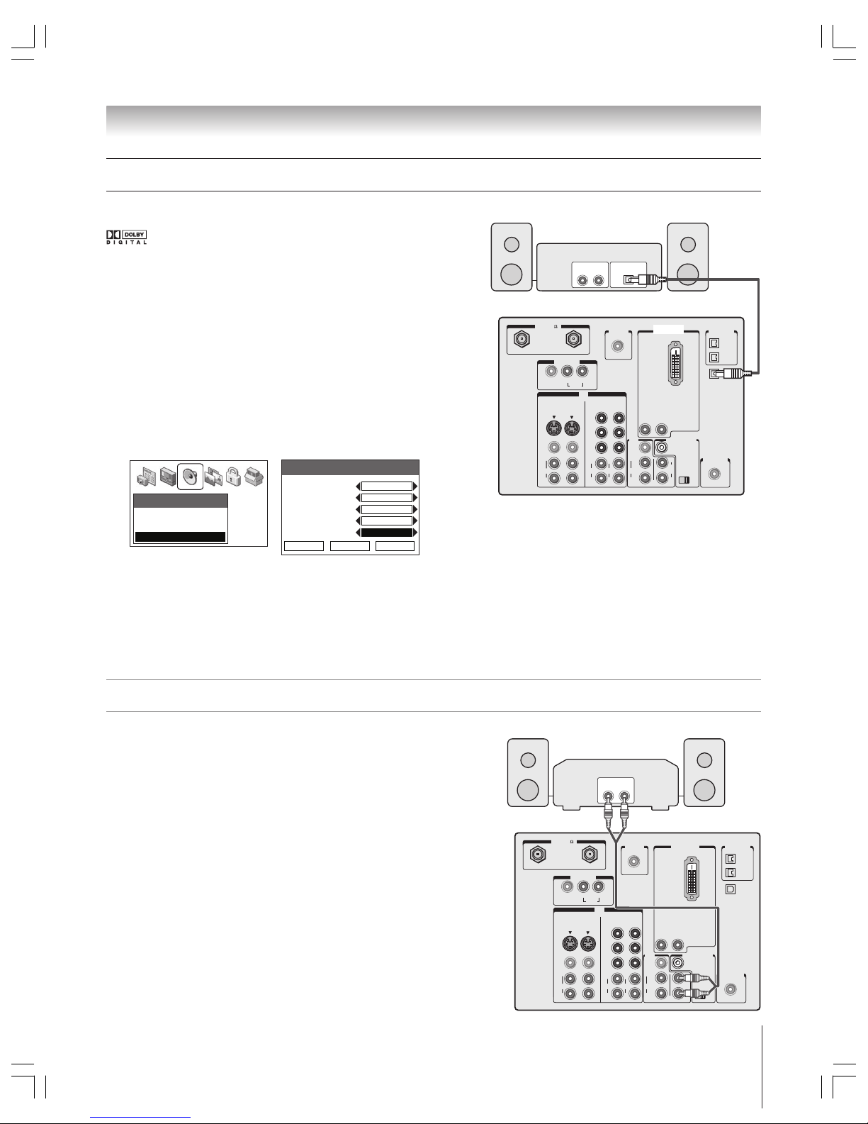
Copyright © 2003 TOSHIBA CORPORATION. All rights reserved.
19
Chapter 2: Connecting your TV
Connecting a digital audio system
This connection allows you to use external speakers with an
external audio amplifier to adjust the sound level.
You will need:
one pair of standard audio cables
To control the audio:
Turn on the TV and the stereo amplifier.
Turn off the TV’s built-in speakers (see “Turning off the built-in
speakers” on page 79).
Note: To hear sound when using an external audio amplifier,
the volume of both the TV and the amplifier must be set to a
reasonable listening level.
IN
ANT( 75
)
REC OUT
ANT-1 ANT-2
PB
PR
Y
L/
MONO
AUDIO
S-VIDEO
VIDEO 1 VIDEO 2
COLOR
STREAM
HD-1
COLOR
STREAM
HD-2
VIDEO
R
L
AUDIO
VIDEO
R
L
AUDIO
R
PB
PR
Y
L
AUDIO
R
VIDEO
L/
MONO
ON OFF
L
AUDIO
AUDIO
VAR
R R
OUT
CHANNEL IN
AUDIO CENTER
DVI/HDCP IN
R
AUDIO
L
G-LINK
IR OUT
DIGITAL
AUDIO OUT
IEEE1394
1
IEEE1394
2
TheaterNet
TheaterNet
LINE IN
LR
TV
Analog audio amplifier
Connecting an analog audio system
The TV’s DIGITAL AUDIO OUT jack outputs a
or 2-channel down-mixed PCM (pulse-code
modulation) signal for use with an external Dolby Digital
decoder or other external audio system with optical audio input.
You will need:
one optical audio cable
To control the audio:
Turn on the TV and the digital audio device.
Press MENU on the TV’s remote control and open the AUDIO
menu.
Highlight AUDIO SETUP and press ENTER.
In the OPTICAL OUTPUT FORMAT field, select either
DOLBY DIGITAL or PCM, depending on your device (see
“Selecting the optical audio output format” on page 79).
Audio
Audio Settings
Advanced Audio Settings
Audio Setup
Audio Setup
MTS
Language
Speakers
Audio Out
Optical Output Format
Save Done Reset
English
Stereo
On
Main
Dolby Digital
Turn off the TV’s built-in speakers (in the same AUDIO
SETUP menu, above; also see “Turning off the built-in
speakers” on page 79).
Or you can use the TV’s built-in speakers as center channel
speakers by following the connection instructions on page 20.
IN
ANT( 75
)
REC OUT
ANT-1 ANT-2
PB
PR
Y
L/
MONO
AUDIO
S-VIDEO
VIDEO 1 VIDEO 2
COLOR
STREAM
HD-1
COLOR
STREAM
HD-2
VIDEO
R
L
AUDIO
VIDEO
R
L
AUDIO
R
PB
PR
Y
L
AUDIO
R
VIDEO
L/
MONO
ON OFF
L
AUDIO
AUDIO
VAR
R R
OUT
CHANNEL IN
AUDIO CENTER
DVI/HDCP IN
R
AUDIO
L
G-LINK
IR OUT
DIGITAL
AUDIO OUT
IEEE1394
1
IEEE1394
2
TheaterNet
TheaterNet
LINE IN Optical IN
LR
TV
Dolby Digital decoder or
other digital audio system
Optical Audio
IN
Note:
• Some audio systems may not be compatible with Dolby
Digital bitstream signals. Older audio systems that are not
compatible with standard optical out signals may not work
properly, creating a high noise level, which may damage
speakers or headphones.
•The DIGITAL AUDIO OUT jack may not output some
digital audio sources because of copy restrictions.
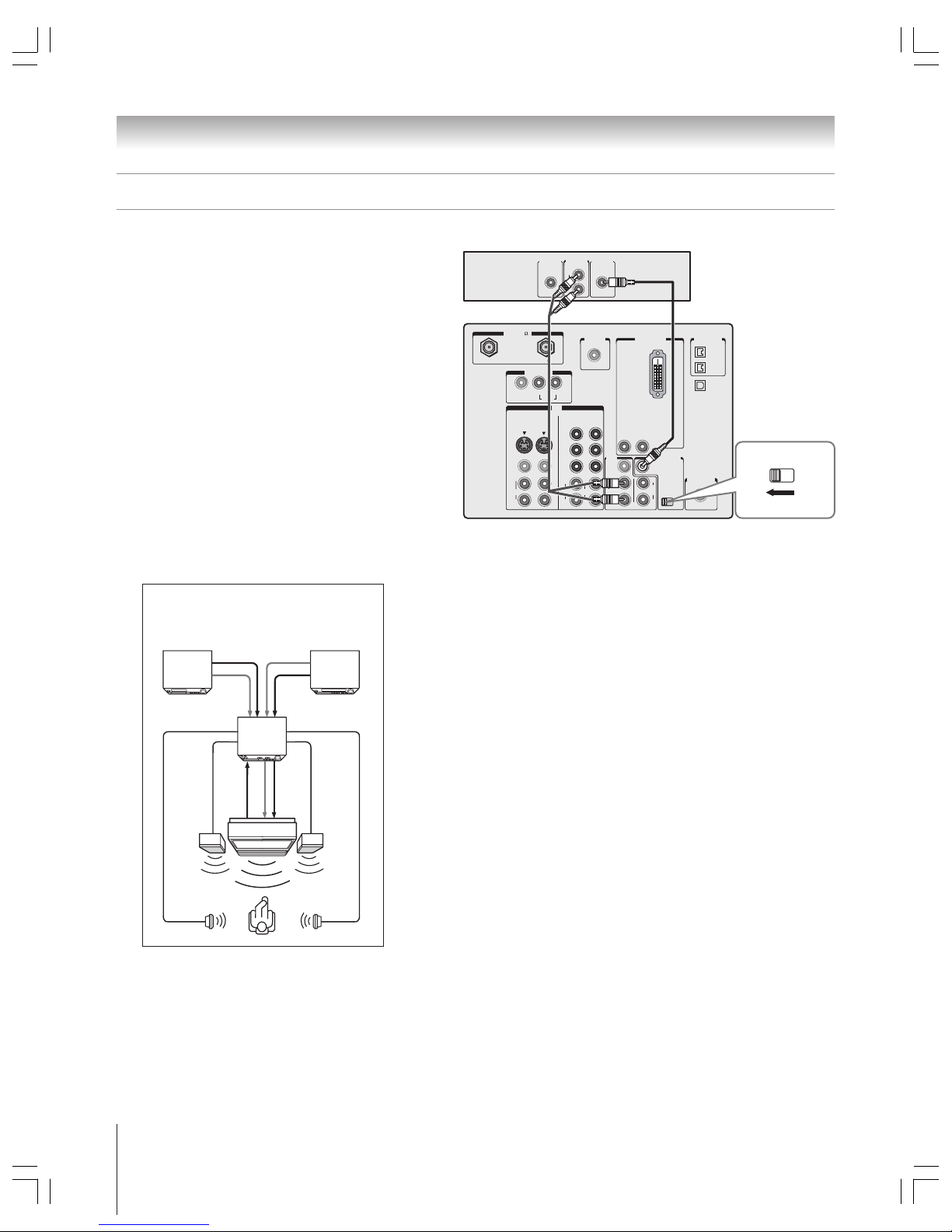
Copyright © 2003 TOSHIBA CORPORATION. All rights reserved.
20
Chapter 2: Connecting your TV
IN
ANT( 75
)
REC OUT
ANT-1 ANT-2
P
B
P
R
Y
L/
MONO
AUDIO
S-VIDEO
VIDEO 1 VIDEO 2
COLOR
STREAM
HD-1
COLOR
STREAM
HD-2
VIDEO
R
L
AUDIO
VIDEO
R
L
AUDIO
R
P
B
P
R
Y
L
AUDIO
R
VIDEO
L/
MONO
ON OFF
L
AUDIO
AUDIO
VAR
R R
OUT
CHANNEL IN
AUDIO CENTER
DVI/HDCP IN
R
AUDIO
L
G-LINK
IR OUT
DIGITAL
AUDIO OUT
IEEE1394
1
IEEE1394
2
TheaterNet
TheaterNet
L
AUDIO
R
ON OFF
Video
OUT
AudioINCenter
OUT
Dolby Pro Logic surround sound
system connection example
Connecting an A/V receiver
T V
Right
speaker
Left
speaker
Surround
speaker L
Surround
speaker R
VCR
A/V receiver
Audio Video
Video
Audio
Video
Audio
center
channel
Audio
LDP/DVD
TV
A/V receiver
This connection allows you to use an A/V (audio/video)
receiver to enhance your TV’s sound. If your sound system
has Dolby Pro Logic surround sound, you can add to the
realism of the sound by using the TV’s internal speakers as
center channel speakers.
You will need:
one set of standard A/V cables
one single audio cable for the audio center channel
Note:
•When the Audio Center Channel ON/OFF switch is in the
ON position, the TV speakers will function as center channel
speakers only.
•To use the TV speakers as normal speakers, set the Audio Center
Channel ON/OFF switch to the OFF position.
• Adjust the volume for the center channel speakers using the
center level control on your A/V receiver.
• Refer to your A/V receiver’s user manual for details about your
surround sound system.
CAUTION—To avoid damaging the TV’s speakers:
•Turn off the TV before connecting or disconnecting the Audio Center
Channel cable.
• Do not connect from the A/V receiver’s amplified center OUT jack to the
TV’s Audio Center Channel IN jack.
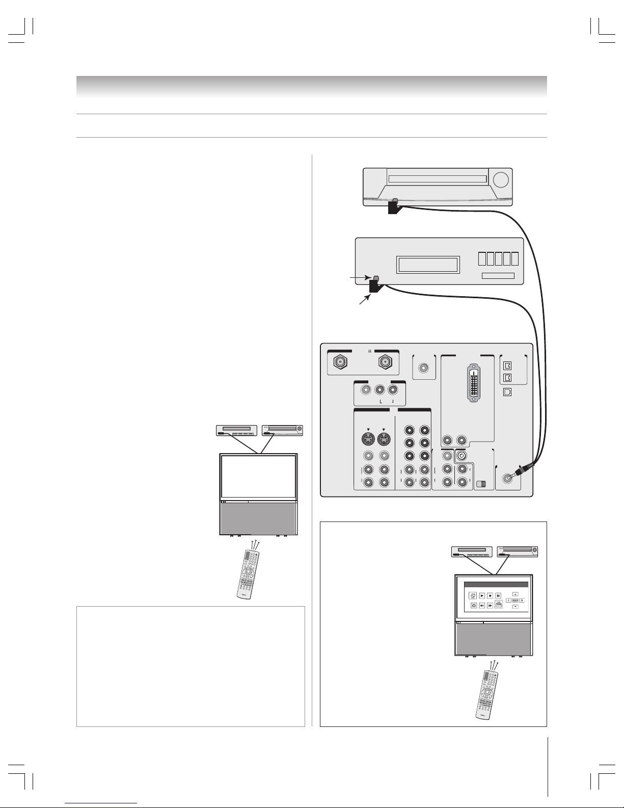
Copyright © 2003 TOSHIBA CORPORATION. All rights reserved.
21
Chapter 2: Connecting your TV
For additional control options
for your home theater system,
set up the TheaterNet on-screen
device control feature. You can
use this feature to control many
IR remote-controlled devices
(and IEEE-1394 devices) using
the on-screen control icons.
You can use the TV’s IR OUT jack (infrared pass-through)
to remotely operate (through the TV) many infrared
remote-controlled devices (such as a Toshiba infrared
remote-controlled VCR or DVD player) enclosed within
an entertainment center or similar cabinet. Without the
IR OUT connection, the device typically would need to be
visible to operate it remotely.
You will need:
one dual-wand IR blaster cable (included with your TV)
other audio/video cables as required to connect the device(s)
to the TV (see pages 12–20)
To connect the IR blaster cable:
1. Locate the infrared sensor on the front of your device.
This sensor is marked on some devices.*
2. Align one of the IR blaster cable’s wands about 1 inch away
from the infrared sensor on the front of the device and
attach it using the enclosed mounting tape. If you have a
second device, attach the second wand in a similar manner.
(See illustration at right.)
Note: If you do not have a second device, coil the second wand
with a rubber band and leave it behind the TV.
3. Plug the IR blaster cable’s plug into the TV’s IR OUT jack.
Controlling infrared remote-controlled devices through the TV (IR pass-through)
To control the device(s):
Point the TV remote control
(programmed to operate the device;
see pages 47–49) or the device’s
remote control at the front of the TV
and press the button for the desired
function. The signal passes from the
remote control through the TV to
the device via the IR blaster cable.
Note:
• If you use the device’s remote control
to operate the device, you also will
need to use the TV’s remote control to
operate the TV.
• For additional control options, see
“TheaterNet on-screen device control”
at right.
1
2
3
4
56
7
8
9
100/
0
E
NT
T
V
C
A
B
L
E
/S
A
T
V
C
R
P
O
W
ER
+
1
0
DVD
AUDIO
1
AUDIO2
AC
T
I
O
N
M
OD
E
P
IC S
I
Z
E
M
E
N
U
LIGHT
S
LEEP
EN
T
E
R
F
A
V
CH
T
V
/
V
C
R
V
O
L
E
X
I
T
D
I
SC
C
H
R
TN
DV
D
RTN
D
V
D
C
L
E
A
R
S
L
OW/
D
I
R
P
A
US
E
/
S
TE
P
A
M
/
F
M
S
K
I
P
/
S
E
A
R
C
H
P
L
A
Y
RE
W
F
F
S
T
O
P
P
O
P
D
I
R
E
C
T
C
H
F
R
E
E
Z
E
S
P
LIT
C
H
SC
A
N
SO
U
R
C
E
S
W
A
P
P
O
P CH
RE
C
I
N
P
U
T
R
E
C
A
LL
M
U
T
E
L
I
N
K
T
H
E
A
T
E
R
F
A
V
O
R
I
T
E
I
N
F
O
G
U
I
D
E
S
E
T
U
P
T
I
T
L
E
S
U
B
T
I
T
L
E
A
U
D
I
O
F
A
V
IN
ANT( 75
)
REC OUT
ANT-1 ANT-2
P
B
P
R
Y
L/
MONO
AUDIO
S-VIDEO
VIDEO 1 VIDEO 2
COLOR
STREAM
HD-1
COLOR
STREAM
HD-2
VIDEO
R
L
AUDIO
VIDEO
R
L
AUDIO
R
P
B
P
R
Y
L
AUDIO
R
VIDEO
L/
MONO
ON OFF
L
AUDIO
AUDIO
VAR
R R
OUT
CHANNEL IN
AUDIO CENTER
DVI/HDCP IN
R
AUDIO
L
G-LINK
IR OUT
DIGITAL
AUDIO OUT
IEEE1394
1
IEEE1394
2
TheaterNet
TheaterNet
Back of TV
Front of IR-controlled audio device (for example)
Front of IR-controlled DVD player (for example)
IR blaster cable wand
(approx. 1 inch from device)
Infrared
sensor
TheaterNet™ on-screen device control
See pages 45–49 for details on
setting up and using TheaterNet.
See pages 22–24 for details on
connecting IEEE-1394 devices.
Note: The TheaterNet icon controls are the
only device functions available when the icons
are on-screen. To access other device
functions, close the TheaterNet icon window.
1
2
3
4
56
7
8
9
100/
0
ENT
TV
C
A
B
L
E
/S
A
T
VCR
P
O
W
ER
+
1
0
DVD
AUDIO
1
AUDIO
2
AC
T
I
O
N
M
OD
E
P
IC S
I
Z
E
M
E
N
U
LI
GHT
S
LEEP
EN
TE
R
F
A
V
CH
T
V
/
V
C
R
V
O
L
E
X
I
T
D
ISC
C
H
R
TN
DV
D
RTN
D
V
D
C
L
E
A
R
S
L
OW/
D
I
R
P
A
US
E
/
S
T
E
P
A
M
/
F
M
S
K
I
P
/
S
E
A
R
C
H
P
L
A
Y
RE
W
F
F
S
T
O
P
P
O
P
D
I
R
E
C
T
C
H
F
R
E
E
Z
E
S
P
LIT
C
H
SC
A
N
SO
U
R
C
E
S
W
A
P
P
O
P
CH
RE
C
I
N
P
U
T
R
E
C
A
LL
M
U
T
E
L
I
N
K
T
H
E
A
T
E
R
F
A
V
O
R
I
T
E
I
N
F
O
G
U
I
D
E
S
E
T
U
P
T
I
T
L
E
S
U
B
T
I
T
L
E
A
U
D
I
O
F
A
V
IR Home-TheaterLink
DVD
*
If you cannot locate the device’s infrared sensor:
1. Turn OFF the device.
2. Starting at the lower left corner of the device, place the end of the
device’s remote control (with the infrared emitter) so it touches the
front of the device and press POWE R. (Do not use the TV’s remote
control for this step.)
3. If the device turns on, the place the remote control touched the
device is the location of the sensor.
4. If the device does not turn on, move the remote control slightly to the
right and press POWER again.
5. Repeat step 4 until you locate the device’s infrared sensor.
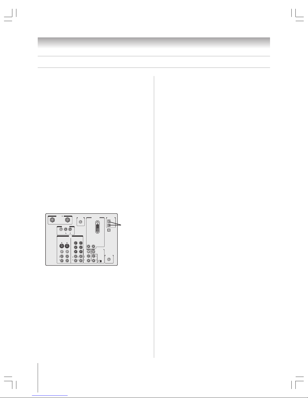
Copyright © 2003 TOSHIBA CORPORATION. All rights reserved.
22
Chapter 2: Connecting your TV
Connecting IEEE-1394 (Firewire™) video devices
You can use the two bi-directional IEEE-1394 ports on the back
of your TV to connect digital video devices that meet CEA
specifications for IEEE-1394 (also known as Firewire).
Because these ports are bi-directional, they can be used for both
playback and recording.
• This TV is not intended for connection to and should not be
used with a PC (personal computer).
• Because IEEE-1394 is an evolving technology, it is possible that some
or all of the connectivity features of a device you connect to the TV
through the IEE E-1394 ports may not operate. You should confirm
that the devices you desire to use with the IEEE-1394 ports will
operate with those ports.
•This TV does not support all possible IEEE-1394 signal types. For
information on signals supported by the IEEE-1394 ports, see
“Supported signals” at right.
•IEEE-1394 cable carries both audio and video information;
no separate audio cables are required for a complete connection.
• See “Using the digital tuner hold” on page 61.
You will need:
one (or two) IEEE-1394 cables
additional A/V cables if your device is analog-compatible
(see “Using analog-compatible IEEE-1394 devices” below).
IN
ANT( 75
)
REC OUT
ANT-1 ANT-2
PB
PR
Y
L/
MONO
AUDIO
S-VIDEO
VIDEO 1 VIDEO 2
COLOR
STREAM
HD-1
COLOR
STREAM
HD-2
VIDEO
R
L
AUDIO
VIDEO
R
L
AUDIO
R
PB
PR
Y
L
AUDIO
R
VIDEO
L/
MONO
ON OFF
L
AUDIO
AUDIO
VAR
R R
OUT
CHANNEL IN
AUDIO CENTER
DVI/HDCP IN
R
AUDIO
L
G-LINK
IR OUT
DIGITAL
AUDIO OUT
IEEE1394
1
IEEE1394
2
TheaterNet
TheaterNet
Two bi-directional
IEEE-1394 ports
TV back panel
Using analog-compatible IEEE-1394
devices
Some digital IEEE-1394 devices are compatible with analog
signals. For example, some D-VHS VCRs can record and play
VHS or S-VHS format videos. Such devices allow you to play
analog tapes that you rented or recorded, or record analog
programs from antenna or Cable TV systems. To use the
IEEE-1394 device’s analog features, you need to connect the
device to the TV using standard A/V cables (or S-video plus
audio cables) in addition to connecting the IEEE-1394 cable.
Note: If you have an IEEE-1394 device connected to both
digital and analog inputs on the TV, the TV automatically
switches between analog and digital modes as needed, when
the initial device access is initiated using the TheaterNet button.
See page 45 for details on using the TheaterNet feature.
Supported signals
The IEEE-1394 ports support the signals listed below only.
Although incompatible video, audio, and digital control signals
cannot be decoded by the TV, these signals may be passed
through the IEEE-1394 cable to other compatible devices.
Incompatible devices may not appear in the TheaterNet menu.
• MPEG-2 digital video signals
Other digital video signals—such as DV video—are
incompatible and must be decoded by the source device and
sent to the TV as analog video (composite or S-video).
• Dolby Digital and MPEG digital audio signals
Other digital audio signals—such as DPM, MP3, and DTS—
are incompatible and cannot be decoded by the TV.
• EIA-775 and D-VHS A/VC digital control
Your TV can serve as the control center for many devices
that are compatible with EIA-775 or A/VC IEEE-1394
control standards (described below).
The TV cannot control IEEE-1394 devices that use any other
control standards.
– EIA-775 digital control allows tuning devices (such as
Cable boxes) to send simple graphics; however, this
standard does not allow the TV to control the Cable box
through IEEE-1394.
– D-VHS A/VC (audio/video control) provides basic
control (such as power, play, stop rewind, fast-forward,
pause, and record), as applicable to the specific device.
Using TheaterNet™ on-screen device
control
You can use the TheaterNet feature to control some IEEE-1394
devices using on-screen control icons. See page 45 for details on
setting up and using the TheaterNet feature.
Note: If the TheaterNet feature does not control your
IEEE-1394, you can try using I R pass-through with the TV’s
remote control (page 21) or use the device’s remote control.
Copyright © 2003 TOSHIBA CORPORATION. All rights reserved.
23
Chapter 2: Connecting your TV
Connecting IEEE-1394 (Firewire™) video devices (continued)
IEEE-1394 device initialization
When you connect a new IEEE-1394 device to the TV and turn
it on, the device immediately announces its presence to the TV
(and other networked IEEE-1394 devices, if any), and the
following device initialization screen automatically appears.
Note: With some devices, it may take up to one minute for this
screen to appear.
New IEEE1394 Device Initialization
Manufacturer
Device Type
Analog Input Used
Custom Label
Edit Label Save
None
Brandname
VCR
1. If you connected your IEEE-1394 device to an analog input
also, use the
yzx •
buttons to select the input in the
ANALOG INPUT USED field; otherwise, leave it set to
“None.” (See “Using analog-compatible IEEE-1394
devices” on page 22.)
2. If you want to label the device, highlight EDIT LABEL,
press ENTER, and then use the
yzx •
buttons to input
the label.
3. Highlight SAVE and press ENTER to save the information.
New IEEE1394 Device Initialization
Manufacturer
Device Type
Analog Input Used
Custom Label
Edit Label Save
VIDEO 1
Brandname
VCR
My D-VHS
Note:
•The TV may not recognize non-A/V or non-compatible
IEEE-1394 devices; however, these devices may still be available
to other compatible IEEE-1394 devices on the network.
•You may be able to use the TV’s remote control to operate some
compatible IEEE-1394 devices. You must first program the
remote control to recognize the device (see pages 30–33).
If you have an IEE E-1394 Cable box or satellite receiver, you
may need to use the remote control that came with the device.
IEEE-1394 device management
The IEEE-1394 device information is saved permanently in the
TV’s memory. You can edit this device information (for
example, to edit the device name, change the analog input
information, or delete the device information from the TV’s
memory if you no longer use that device).
To edit the IEEE-1394 device information:
1. Press MENU and open the SETUP menu.
2. Highlight INSTALLATION and press ENTER. (A new set
of INSTALLATION menu icons will appear on-screen, as
shown in step 3 below).
Setup
Installation
Sleep Timer
On/Off Timer
Digital Tuner Hold
• • • • • • •
Off
Slide Show Interval
• • •
2 Sec
Convergence
3. Open the DEVICES menu, highlight IEEE-1394
DEVICES, and press ENTER.
Devices
IEEE1394 Devices
TheaterNet Devices
4. Highlight the device you want to edit, and follow the
on-screen prompts.
IEEE1394 Device Management
Analog
Brand Type Label Input Connected
Exit
Delete All
Brandname VCR None Yes
Brandname STB VIDEO 2 No
Brandname VCR ColorStr Yes
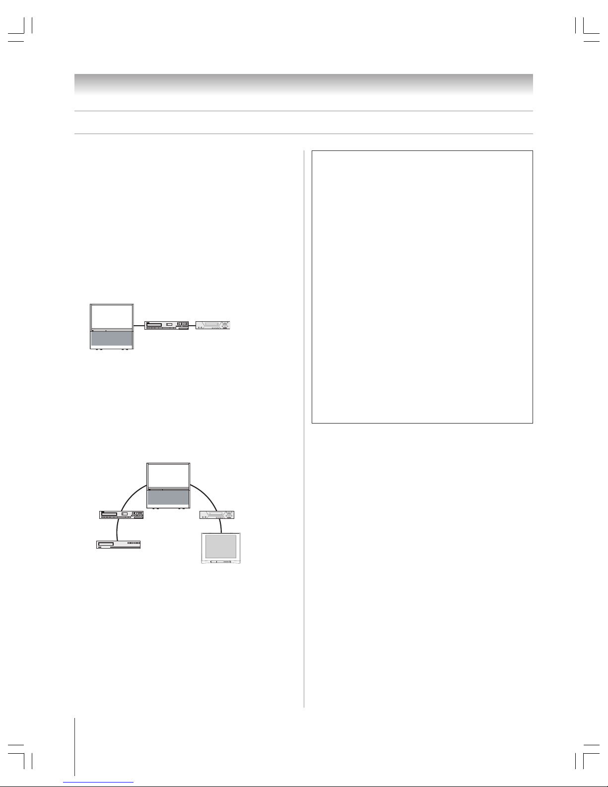
Copyright © 2003 TOSHIBA CORPORATION. All rights reserved.
24
Chapter 2: Connecting your TV
IEEE-1394 device interconnection
IEEE-1394 devices can be interconnected (instead of each
device having to be connected to a separate input on the TV) in
either of two ways: (1) a device-to-device chain connection or
(2) a hub connection.
Chain connection
Connect the first IEEE-1394 device to one of the TV’s
IEEE-1394 inputs, and then connect each subsequent device to
the preceeding device in the chain.
• Read the “Important information” at right.
• Devices in the middle of the chain will need two IEEE-1394
ports for this connection to work as illustrated.
Hub connection
You can connect a chain of IEEE-1394 devices to each of the
TV’s two IEEE-1394 jacks. The TV will then serve as a hub in
your A/V system. Each device can send audio and video
information to any other device in the system.
• Read the “Important information” at right.
• Devices in the middle of the chain will need two IEEE-1394
ports for this connection to work as illustrated.
Connecting IEEE-1394 (Firewire™) video devices (continued)
Important information regarding
IEEE-1394 device interconnection
• Do not loop the last device in the chain back to the TV.
If the device chain is looped, the TV may not work properly with the
other devices in the chain.
• Place devices with the slowest communication speed at
the end of each chain. If a device with a slower communication
speed is placed ahead of a faster device in the chain, the signal
from the slower device will interfere with the signal from the faster
device. To determine the communication speed of an IEEE-1394
device, look for an “S” number near the device’s IEE E-1394
connector. The higher the “S” number, the faster the device. If your
device is not marked with an “S” number, look in the device’s user
manual or call the device manufacturer’s technical support number.
• If your IEEE-1394 device has a two-position power
switch, place the device at the end of the chain or leave
the power switch ON at all times. If the power switch is OFF,
it will interfere with signals from devices behind it in the chain.
• The maximum length for an IEEE-1394 cable between
each device is 15 feet.
•This TV is an IEEE-1394A device. The IEEE-1394B protocol is
faster and intended to allow for longer distances between devices
and multi-room systems. IEEE-1394A–to–IE EE-1394B converters
(available at some electronics suppliers) may allow compatibility of
IEEE-1394B devices with your existing I EEE-1394A devices.
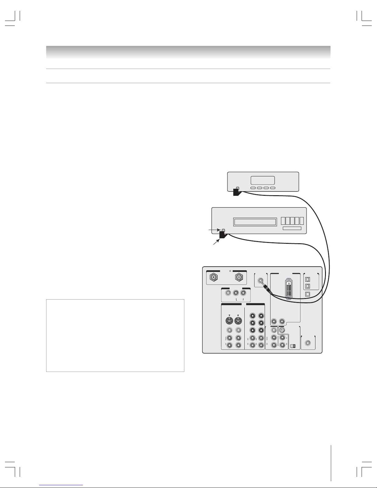
Copyright © 2003 TOSHIBA CORPORATION. All rights reserved.
25
Chapter 2: Connecting your TV
After you connect your devices to the TV (pages 12–24), you will need to connect the G-LINK cable (either of the dual-wand IR
blaster cables included with your TV) from your VCR and Cable box (if applicable) to the G-LINK jack on the TV. This connection
is necessary to enable the following features of your TV Guide On Screen
™
system:
• If you have a Cable box, you need to connect the G-LINK cable from the Cable box to the G-LINK jack to receive the TV Guide
On Screen system’s program listings for your Cable service.
• If you have a VCR, you need to connect the G-LINK cable from the VCR to the G-LINK jack to use the TV Guide On Screen
system’s one-touch recording feature.
G-LINK connection
This connection is necessary to enable the TV Guide On Screen™ system’s device control and one-touch recording features.
IN
ANT( 75
)
REC OUT
ANT-1 ANT-2
PB
PR
Y
L/
MONO
AUDIO
S-VIDEO
VIDEO 1 VIDEO 2
COLOR
STREAM
HD-1
COLOR
STREAM
HD-2
VIDEO
R
L
AUDIO
VIDEO
R
L
AUDIO
R
PB
PR
Y
L
AUDIO
R
VIDEO
L/
MONO
ON OFF
L
AUDIO
AUDIO
VAR
R R
OUT
CHANNEL IN
AUDIO CENTER
DVI/HDCP IN
R
AUDIO
L
G-LINK
IR OUT
DIGITAL
AUDIO OUT
IEEE1394
1
IEEE1394
2
TheaterNet
TheaterNet
Back of TV
Front of VCR
Front of Cable box
Infrared
sensor
G-LINK (IR blaster) cable wand
(approx. 1 inch from device)
To connect to the G-LINK jack:
1. Locate the infrared sensor on the front of your VCR or
Cable box. The sensor is marked on some devices.*
2. Align one of the G-LINK (IR blaster) cable’s wands about
1 inch away from the infrared sensor on the front of the
VCR and attach it using the included mounting tape.
If you have a Cable box, attach the other wand in a similar
manner. (See illustration at right.)
Note: If you do not have a Cable box, coil the second wand
with a rubber band and leave it behind the TV.
3. Plug the G-LINK (IR blaster) cable’s plug into the TV’s
G-LINK jack.
For details on setting up the TV Guide On Screen system:
See page 36.
For details on using the TV Guide On Screen interactive
program guide:
See page 53.
*
If you cannot locate the device’s infrared sensor:
1. Turn OFF the device.
2. Starting at the lower left corner of the device, place the end of the
device’s remote control (with the infrared emitter) so it touches the
front of the device and press POWE R. (Do not use the TV’s remote
control for this step.)
3. If the device turns on, the place the remote control touched the
device is the location of the sensor.
4. If the device does not turn on, move the remote control slightly to the
right and press POWER again.
5. Repeat step 4 until you locate the device’s infrared sensor.
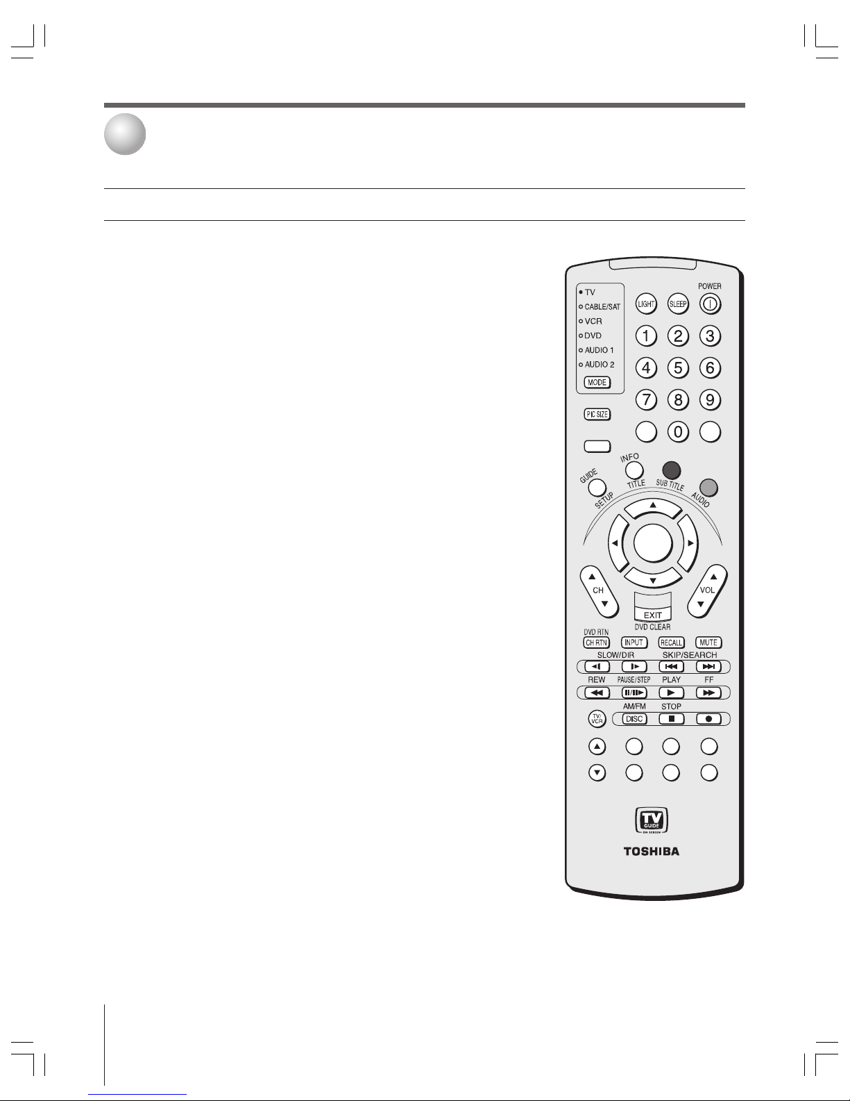
Copyright © 2003 TOSHIBA CORPORATION. All rights reserved.
26
Using the remote control
3
Note:
The error message “Not Available” will
appear if you press a key for a function
that is not available.
CT-90168
VCR+REC
+
PAG E –
ACTION
ENTER
MENU
THEATER
NET
F
A
V
SPLIT POP DIRECT CH FREEZE
SWAP CH SCAN SOURCE
POP CH
–
100
+10
The buttons used for operating the TV only are described here. For a complete list
of the remote control’s functions, see the remote control functional key chart on
pages 28–29.
POWER
turns the TV on and off
SLEEP
accesses the sleep timer (page 82)
LIGHT
The first press of the LIGHT button lights the keypad and turns on the
Illumination mode. With the Illumination mode on, pressing any other key lights the
keypad for 5 seconds (10 seconds if you’re in programming mode). Subsequent presses
of the LIGHT button toggle between turning the Illumination mode on and off.
Channel Numbers (0–9, 100)
directly access channels (page 42)
MODE
cycles through the six device modes: TV, CABLE/SAT, VCR, DVD, AUDIO1,
and AUDIO2. The mode indicator light will remain lit for a few seconds (page 27).
PIC SIZE
cycles through the five pictures sizes: Natural, Theater Wide 1/2/3, and Full
(page 64)
THEATER NET
accesses the on-screen IR device control icons (page 46)
MENU
accesses the menu system (page 35)
GUIDE
opens the TV Guide On Screen system (page 53)
INFO
provides detailed information on highlighted items in the TV Guide On Screen
system (page 56)
BLUE and GREEN buttons
select menu-specific functions in the TV Guide On Screen
system (page 55)
ENTER
activates highlighted items in the main menu system and the TV Guide
On Screen system
yz x •
select or adjust programming menus
FAV
accesses the favorite channel search function (page 44)
CH yz
cycles through programmed channels when no menu is on-screen (page 42);
functions as page up/down when a menu is on-screen or when the TV Guide
On Screen system is open (page 53)
VOL yz
adjusts the volume level
EXIT
closes on-screen menus and the TV Guide On Screen system
CH RTN
returns to the last viewed channel (page 63)
INPUT
selects the video input source (page 61)
RECALL
displays TV setting information on-screen (page 83)
MUTE
reduces or turns off the sound (page 76)
TV/VCR
press to select TV mode to view one program while recording another
SPLIT
turns the POP feature on and off (page 68)
POP CH yz
selects the POP (picture-out-picture) channel (page 68)
POP DIRECT CH
allows direct access to POP channels (page 68)
FREEZE
freezes the main picture in the double-window (page 69)
SWAP
switches the main and POP pictures (page 69)
CH SCAN
allows access to the programmed channel search function (page 70)
SOURCE
selects the POP picture source (page 68)
Learning about the remote control
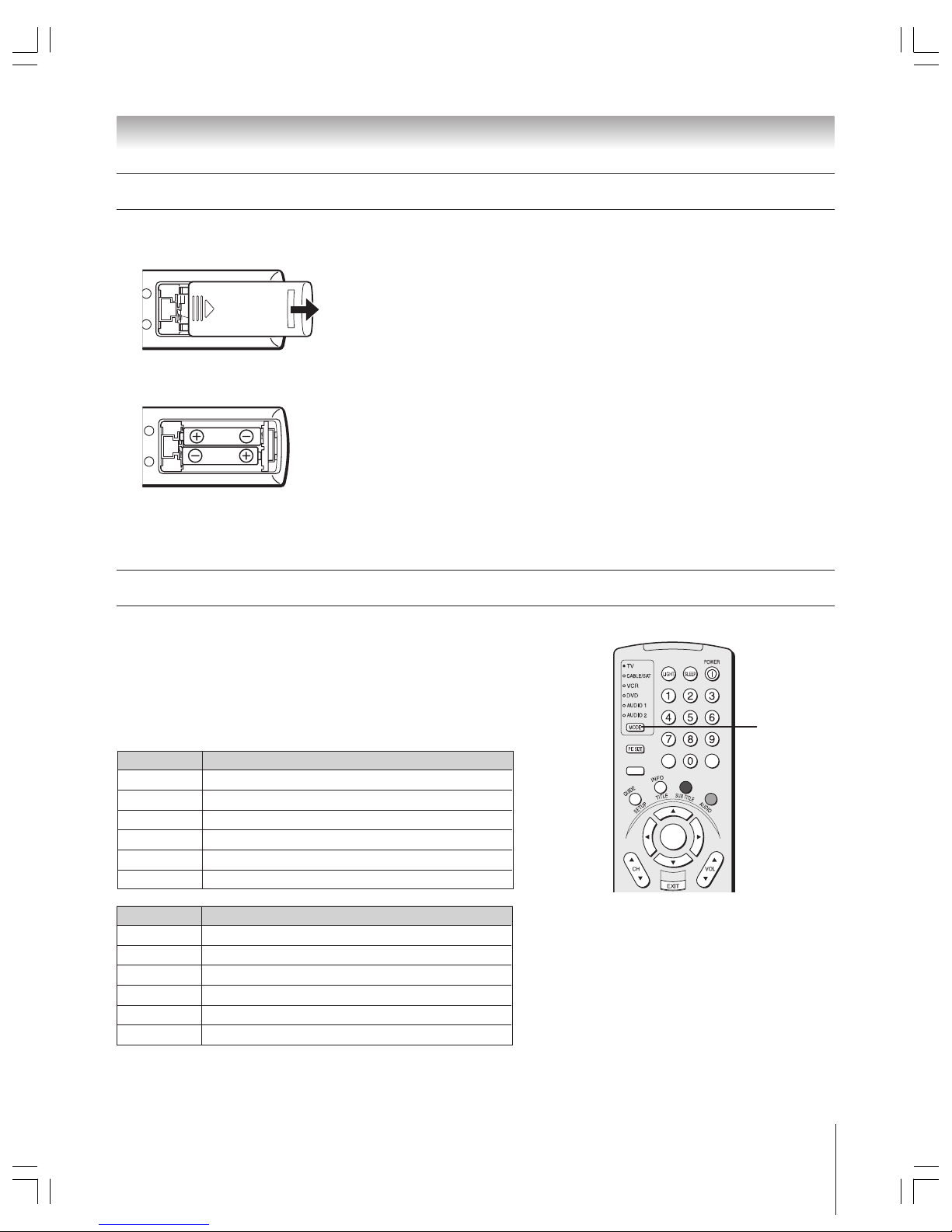
Copyright © 2003 TOSHIBA CORPORATION. All rights reserved.
27
Chapter 3: Using the remote control
MODE Device mode control after programming
TV Toshiba TV
CABLE/SAT Multi-brand Cable, Satellite
VCRMulti-brand VCR, DVD, LD, Cassette
DVDMulti-brand DVD, VCR, LD, Cassette
AUDIO 1 Multi-brand Audio: Amp., Tuner, Misc.Audio, CD/MD
AUDIO 2 Multi-brand Audio: CD/MD, Amp., Tuner, Misc.Audio
Note:
Although your new TV’s remote control includes
codes for many devices, it may not include
codes for some or all of the features on certain
devices you wish to control. If you are unable to
program the TV’s remote control to operate
your device or some of the features on that
device, use the device’s remote control or the
controls on the device.
MODE
+
PAGE –
ACTION
ENTER
MENU
THEATER
NET
F
A
V
–
100
+10
Your TV remote control has one dedicated TV mode and five programmable
multi-brand modes: CABLE/SAT, VCR, DVD, AUDIO 1, and AUDIO 2.
The default device modes and programmable device modes are listed below.
Note: The TV remote control is preprogrammed to operate most Toshiba devices.
If you own a non-Toshiba device or a Toshiba device that the remote control is not
preprogrammed to operate, you will need to program the remote control. See
“Programming the remote control to operate your other devices” on page 30.
MODE Default device mode control (before programming)
TV Toshiba TV
CABLE/SAT Toshiba Satellite receiver
VCRToshiba VCR
DVDToshiba DVD
AUDIO 1 Pioneer Audio receiver
AUDIO 2 Pioneer LD
Using the remote control MODE button to control other devices
Caution:
• Dispose of batteries in a designated disposal
area. Do not throw batteries into a fire.
• Do not mix battery types or combine used
batteries with new ones.
• If the remote control does not operate
correctly, or if the operating range becomes
reduced, replace both batteries with new
ones.
• If the batteries are dead or if you will not use
the remote control for a long time, remove
the batteries to prevent battery acid from
leaking into the battery compartment.
To install the remote control batteries:
1. Slide the battery cover off the back of the remote control.
2. Install two “AA” size alkaline batteries. Match the + and – symbols on the
batteries to the symbols on the battery compartment.
3. Slide the battery cover on to the remote control until the lock snaps.
Installing the remote control batteries

Copyright © 2003 TOSHIBA CORPORATION. All rights reserved.
28
Chapter 3: Using the remote control
Key Label
Toshiba TV Cable Satellite VCR DVD/LD Receiver CD/MD Cassete
(TV) (CBL/SAT) (CBL/SAT) (AUDIO) (AUDIO) (VCR)
LIGHT Lights the remote key, and toggles between enabled and disabled Illumination mode.
SLEEP Sleep timer --- --- --- --- --- --- --POWER Power Power Power Power Power Power Power Power
1Digit 1 Digit 1 Digit 1 Digit 1 Digit 1 AV input 1 Digit 1 Digit 1
2Digit 2 Digit 2 Digit 2 Digit 2 Digit 2 AV input 2 Digit 2 Digit 2
3Digit 3 Digit 3 Digit 3 Digit 3 Digit 3 AV input 3 Digit 3 Digit 3
4Digit 4 Digit 4 Digit 4 Digit 4 Digit 4 AV input 4 Digit 4 Digit 4
5Digit 5 Digit 5 Digit 5 Digit 5 Digit 5 CD Digit 5 Digit 5
6Digit 6 Digit 6 Digit 6 Digit 6 Digit 6 Tuner Digit 6 Digit 6
MODE Remote control device mode selection
PIC SIZE Selects the TV TV TV TV TV TV TV
image shape.
7Digit 7 Digit 7 Digit 7 Digit 7 Digit 7 Phono Digit 7 Digit 7
8Digit 8 Digit 8 Digit 8 Digit 8 Digit 8 Cassette Digit 8 Digit 8
9Digit 9 Digit 9 Digit 9 Digit 9 Digit 9 Aux Digit 9 Digit 9
100/– - (Digital --- - (Sub CH) 100 +10 --- --- ---
- separator)
0Digit 0 Digit 0 Digit 0 Digit 0 Digit 0 --- Digit 0, 10 --GUIDE/SETUP
Guide --- Guide --- DVD setup --- --- ---
INFO/TITLE Guide Info --- INFO --- TITLE= --- --- ---
Top menu
(BLUE) / Blue --- --- --- Subtitle --- --- ---
SUBTITLE Guide Key
(GREEN) / Green --- --- --- Audio --- --- ---
AUDIO Guide Key
THEATERNET
TheaterNet
--- --- --- --- --- --- ---
MENU/ Menu/ --- Action, --- Menu --- --- --ACTION Guide Menu Menu
y (FAV) Menu select --- Menu select --- Menu select --- --- ---
up (FAV) up up
z Menu select --- Menu select --- Menu select --- --- ---
down down down
x • Menu select --- Menu select --- Menu select --- --- ---
left/right left/right left/right
ENTER Enter --- Select --- Enter --- --- --VOL
yz Volume Volume Volume Volume Volume Volume Volume Volume
up/down* up/down* up/down* up/down* up/down* up/down* up/down* up/down*
EXIT/ Exit --- Exit --- DVD clear --- --- ---
DVD CLEAR
CH
yz Channel Channel Channel Channel --- Channel --- ---
PAGE +/– up/down up/down up/down up/down up/down
INPUT TV/Video TV TV VCR input TV --- TV TV
select
MUTE
Sound mute* Sound mute* Sound mute* Sound mute* Sound mute* Sound mute* Sound mute* Sound mute*
RECALL On-screen
--- ---
On-screen On-screen --- --- ---
display display display
Remote Control functional key chart
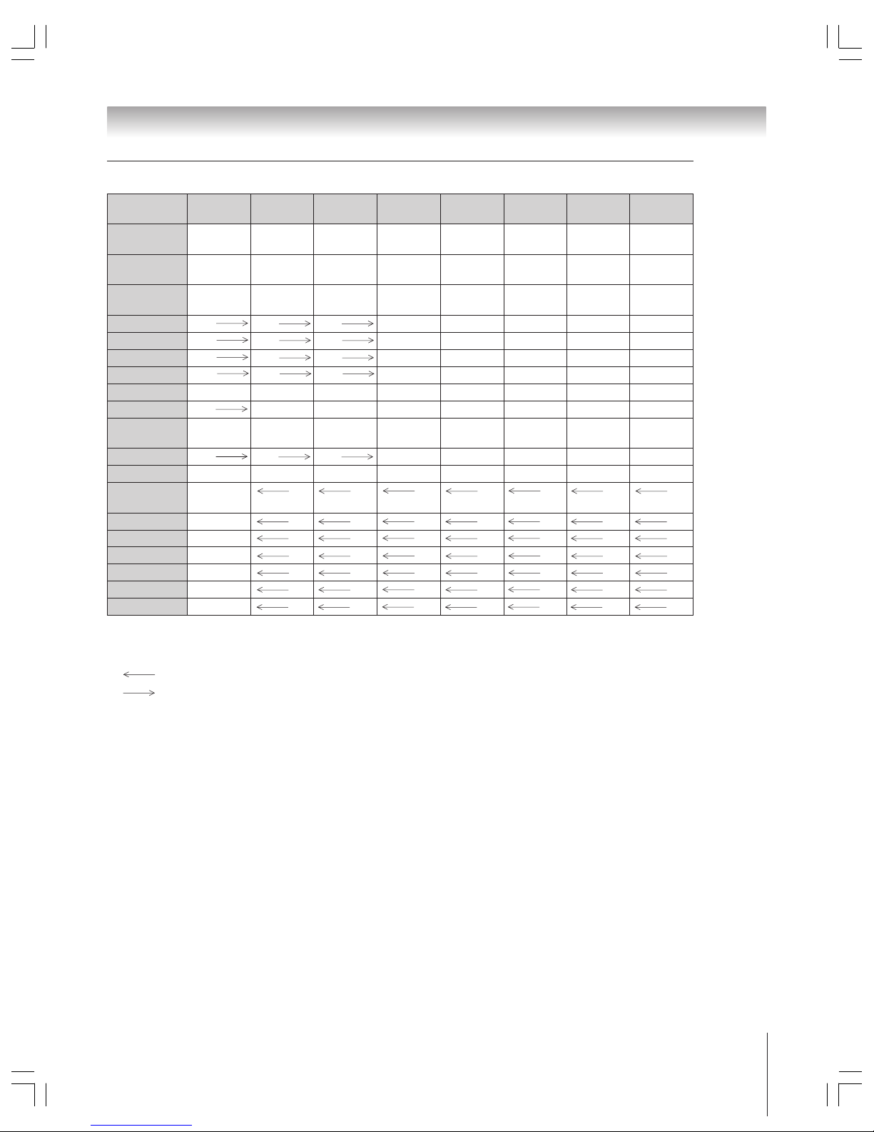
Copyright © 2003 TOSHIBA CORPORATION. All rights reserved.
29
Chapter 3: Using the remote control
Key Label
Toshiba TV Cable Satellite VCR DVD/LD Receiver CD/MD Cassete
(TV) (CBL/SAT) (CBL/SAT) (AUDIO) (AUDIO) (VCR)
CH RTN/ Previous Previous Previous --- DVD --- --- --DVD RTN channel channel channel return
SLOW/
•
--- --- --- Slow FWD Slow FWD --- --- ---
DIR x--- --- --- --- Slow REV --- --- --SKIP/
•
--- --- --- --- Skip FWD
---
Skip FWD
---
SEARCH x--- --- --- --- Skip REV
---
Skip REV
---
REW VCR VCR VCR Rewind Rewind
---
Rewind Rewind
PAUSE/STEP VCR VCR VCR Pause Pause
---
Pause Pause
PLAY VCR VCR VCR Play Play
---
Play Play
FF VCR VCR VCR Fast FWD Fast FWD --- Fast FWD Fast FWD
TV/VCR VCR
---
TV/SAT TV/VCR --- --- --- Reverse
AM/FM --- --- --- --- Disc shift AM/FM Disc shift Deck side
DISC A/B switch
STOP VCR VCR VCR Stop Stop --- Stop Stop
REC
/VCR+
VCR+/REC --- --- Record --- --- --- Record
POP CH
yz
POP channel TV TV TV TV TV TV TV
up/down
SPLIT POP Split TV TV TV TV TV TV TV
POP DIRECT CH POP Direct ch
TV TV TV TV TV TV TV
FREEZE POP Freeze TV TV TV TV TV TV TV
SWAP POP Swap TV TV TV TV TV TV TV
CH SCAN POP
Ch scan
TV TV TV TV TV TV TV
SOURCE POP Source TV TV TV TV TV TV TV
Notes:
• “---” will send nothing.
•“ TV” will jump to TV.
•“ VCR” will jump to last active VCR or DVD. Active VCR/DVD is defined as the mode that remains for a minimum of 5 seconds,
or if a key is pressed in that mode.
1) Backlight key is toggle. Does not send IR.
2) Volume will punch thru to TV by default. When the volume is unlocked, all the devices will have their own volume if their ID has volume
data. The AUD (Receiver, CD) Modes will have its own volume if Volume lock is done to TV, CBL/SAT, VCR, or DVD. See “Using the
volume lock feature” on page 31.
3) Will punch thru to last active VCR or DVD. Active VCR/ DVD is defined as the Mode that remains for a minimum of 5 Seconds, or if a
key is pressed in that Mode.
Remote Control functional key chart (continued)
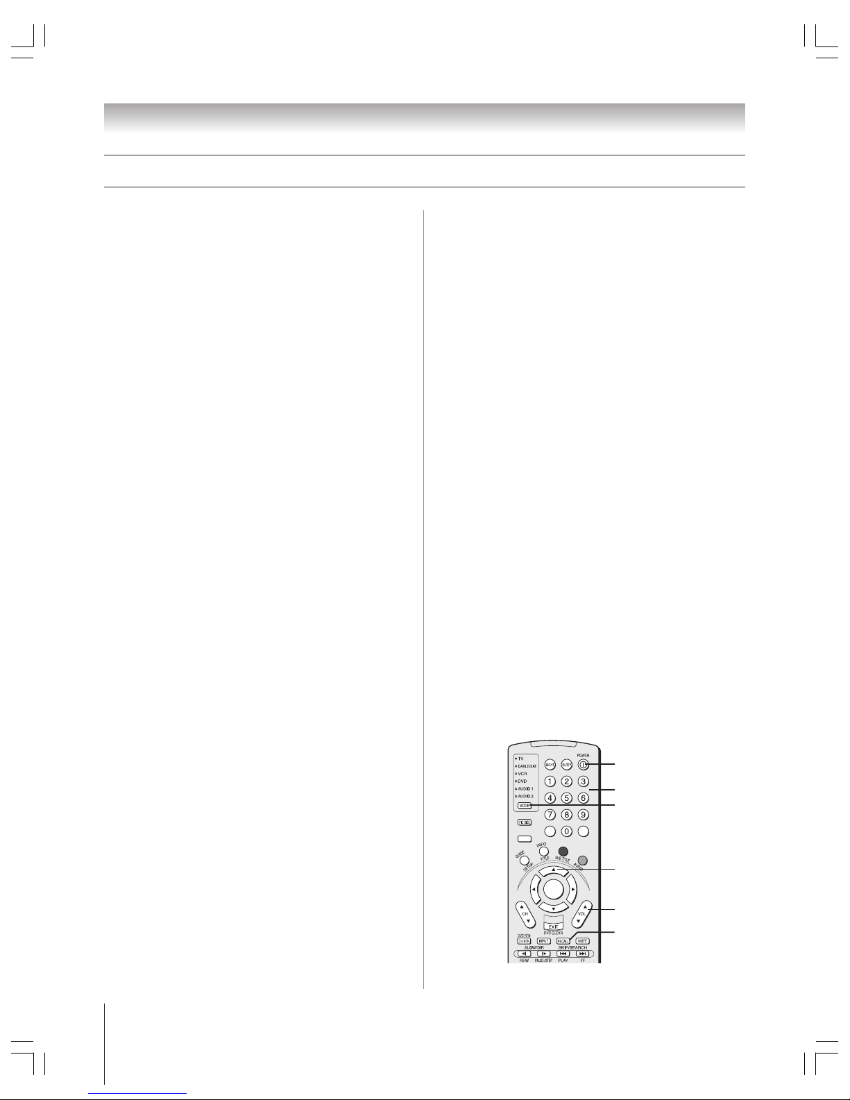
Copyright © 2003 TOSHIBA CORPORATION. All rights reserved.
30
Chapter 3: Using the remote control
Programming the remote control to operate your other devices
Searching and sampling the code
of a device (8500)
If you do not know the device code for a particular device, you
can cycle the remote control through the available codes for that
device mode and sample the functions to find the code that
operates the target device. The keys available to be sampled,
provided they are applicable to that mode, are POWER, 1,
VOL y, CH y, and PLAY. Invalid keys will be ignored while in
program mode.
To cycle through each available device code and sample its
functions:
1. Press MODE to select the mode you want to set up.
2. While holding down RECALL, press 8 – 5 – 0 – 0.
The remote control will enter program mode.
3. Point the remote control at the target device and press
POWER (or other function buttons that are available to be
sampled).
4. If the device responds to the remote control:
Press RECALL to store the device code. The mode
indicator will blink twice and the remote control will exit
the program mode.
If the device does not respond to the remote control:
Press y, and then press POWER.
Repeat this step until the device responds to the remote
control, and then press RECALL.
Note: When a search cycle is completed, the mode
indicator will blink three times. The remote control will
begin to cycle through the available codes again. If no key
is pressed within 10 seconds while programming, the
remote control will exit the program mode and return to the
previous code.
Device code setup
1. Refer to the multi-brand remote control device code table
on pages 32–33 to find the code for the brand of your
device.
If more than one code is listed, try each one separately until
you find the one that works.
2. Press MODE until the Mode indicator for the device
(CABLE/SAT, VCR, DVD, AUDIO 1, AUDIO 2) lights
up.
3. While holding down the RECALL button, press the
Channel Number buttons to enter the four-digit code for
your brand of device. If a valid code is entered, the mode
indicator will blink twice. If an invalid code is entered, the
mode indicator will blink one long blink.
4. Point the remote control at the device and press POWER to
test the code.
If the device responds to the remote control:
You have entered the correct code.
If the device does not respond to the remote control:
You may have entered the wrong code. Repeat steps 3
and 4 using another code.
Note: In addition to POWER, confirm that all necessary keys
on the TV remote control operate your device. If some keys
are not operational, repeat the device code setup using
another code (if other codes are listed for your device).
If, after trying all listed codes, the necessary keys do not
operate your device, use the device’s original remote control.
5. Press MODE to select the TV mode to control the TV.
Note:
• Although the TV remote control includes codes for many devices, it may
not include codes for some or all of the features on certain devices you
wish to control. If you are unable to program the TV remote control to
operate your device or some of the features on that device, use the
device’s remote control or the controls on the device.
• Each time you change the batteries you will need to reprogram the
remote control.
• Some newer VCRs respond to either of two codes. These VCRs have a
switch labeled “VCR1/VCR2.” If your VCR has this kind of switch and
does not respond to the codes for your VCR brand, set the switch to the
other position (“VCR1” or “VCR2”) and reprogram the remote control.
+
PAGE –
ACTION
ENTER
MENU
THEATER
NET
F
A
V
–
100
+10
POWER
Numbers
MODE
y
VOL y/z
RECALL
 Loading...