

Page 1

STE 58769–
INSTRUCTION MANUAL
TOSHIBA MACHINE'S FA SCHOOL TEXTBOOK
FOR
ROBOT TRAINING COURSE
INDUSTRIAL ROBOT SR–H SERIES
(ROBOT CONTROLLER: SR7000)
May, 1998
TOSHIBA MACHINE CO., LTD.
TOKYO, JAPAN
Page 2

Preface
The training session you are going to attend this time is the FA school robot course.
This textbook describes the robot language and basic operating procedures for the user
who will operate the SR–H series industrial robot (robot controller SR7000) in his plant
or factory.
For the detailed specifications and usage of the robot, see the appropriate specifications
manual and instruction manual. When the shipment has reached your office, confirm
the following instruction manuals which are attached to the robot. You are also
requested to read through them before the use.
List of instruction manuals
• Industrial robot SR
series
Startup manual ·········· Simple operating procedures
• Industrial robot SR
series
• Industrial robot SR
series
• Industrial robot SR
series
• Industrial robot SR
series
• Industrial robot SR
series
• Industrial robot SR
series
• Industrial robot SR
series
Copyright 1998 by Toshiba Machine.
All rights reserved.
Operating manual ·········· Detailed operating
Robot language
manual
Interface manual ·········· External I/O, electrical
Transportation and
installation manual
Maintenance manual ·········· Regular inspection and
Communication
manual
Safety manual ·········· Safety measures
procedures
·········· Descriptions of SCOL
language
specifications
·········· Mounting hand and wiring &
piping
maintenance
·········· Communication protocol
No part of this document may be reproduced in any form without obtaining prior written
permission from Toshiba Machine.
The information contained in this manual is subject to change without prior notice to
effect improvements of the robot functions and training details.
STE 58769
– 2 –
Page 3
Industrial Robot Training Schedule
C Course (SR–H Robot): 2.5 Days
Time Descriptions Place
1st day 13:30 ~ 13:40 Greetings at starting the course. Classroom
13:40 ~ 15:00 Explaining the outline. Classroom
15:00 ~ 15:15 Break
15:15 ~ 16:25 Explaining the programming. Classroom
16:25 End
2nd day 8:30 ~ 9:30 Explaining the programming. Classroom
9:30 ~ 10:15 Instructing the safety. Classroom
10:15 ~ 10:25 Move to the training room.
10:25 ~ 11:50 Explaining the operation. Training room
11:50 ~ 12:00 Move to the classroom.
12:00 ~ 13:00 Lunch
13:00 ~ 13:10 Move to the training room.
13:10 ~ 14:45 Training the operation. Training room
14:45 ~ 15:00 Break
15:00 ~ 16:15 Training the operation.
16:15 ~ 16:25 Move to the classroom.
16:25 End Classroom
3rd day 8:30 ~ 8:40 Move to the training room. Classroom
8:40 ~ 9:45 Training the programming. Training room
9:45 ~ 10:00 Break
10:00 ~ 11:50 Training the programming Training room
11:50 ~ 12:00 Move to the classroom.
12:00 ~ 13:00 Lunch
13:00 ~ 13:10 Move to the practical training room.
13:10 ~ 14:45 Training the programming Training room
14:45 ~ 15:00 Break
15:00 ~ 15:50 Explaining the maintenance. Training room
15:50 ~ 16:00 Move to the classroom.
16:00 ~ 16:15 Questions and answers Classroom
16:15 ~ 16:25 Awarding a certificate of completing
the course and greetings at finishing
the course.
16:25 End
– 3 –
STE 58769
Page 4

Robot SR–654HSP
Robot controller SR7000 Teach pendant
– 4 –
STE 58769
Page 5

Table of Contents
Page
1. General Descriptions ...................................................................................... 7
1.1 Basic Robot and Controller .................................................................. 7
1.2 Coordinate System of the Robot .......................................................... 13
1.3 External Input/Output Signals............................................................... 15
1.4 Mode System ....................................................................................... 21
1.5 File ....................................................................................................... 22
2. Robot Language ............................................................................................. 24
2.1 Robot Program..................................................................................... 24
2.2 Robot Language................................................................................... 24
2.3 Subprogram ......................................................................................... 40
2.4 Multi-task.............................................................................................. 42
2.5 List of Robot Language SCOL Instruction Words................................. 45
3. Safety Measures............................................................................................. 49
3.1 Cautions on Safety............................................................................... 49
3.2 Safety Functions .................................................................................. 50
3.3 Safety Measures .................................................................................. 52
4. Training Materials ........................................................................................... 55
4.1 Operating Procedures .......................................................................... 55
4.2 Starting up the Robot ........................................................................... 56
4.3 Program Entry and Position Teaching.................................................. 58
4.4 Test Operation ..................................................................................... 65
4.5 Internal Automatic Operation................................................................ 68
4.6 Ending an Operation ............................................................................ 70
4.7 File Operation....................................................................................... 71
4.8 Error Display and Reset ....................................................................... 76
4.9 Utility .................................................................................................... 78
4.10 Operation of Auxiliary Signals .............................................................. 81
4.11 File Selection........................................................................................ 82
– 5 –
STE 58769
Page 6

Page
5. Maintenance and Inspection ........................................................................... 85
5.1 Maintenance Schedule......................................................................... 85
5.2 Maintenance/Inspection Items.............................................................. 87
6. Exercises of Robot Language SCOL .............................................................. 95
Appendixes
Appendix 1 Example Answers to Exercises of Robot Language SCOL ....... 99
Appendix 2 Creating an Error Insertion Monitor Program............................. 108
Appendix 3 Mounting the Hand, Wiring & Piping.......................................... 111
Appendix 4 Mass of Load and Load Offset .................................................. 113
Appendix 5 Restoring Zero Position Data .................................................... 115
– 6 –
STE 58769
Page 7
1. General Descriptions
1.1 Basic Robot and Controller
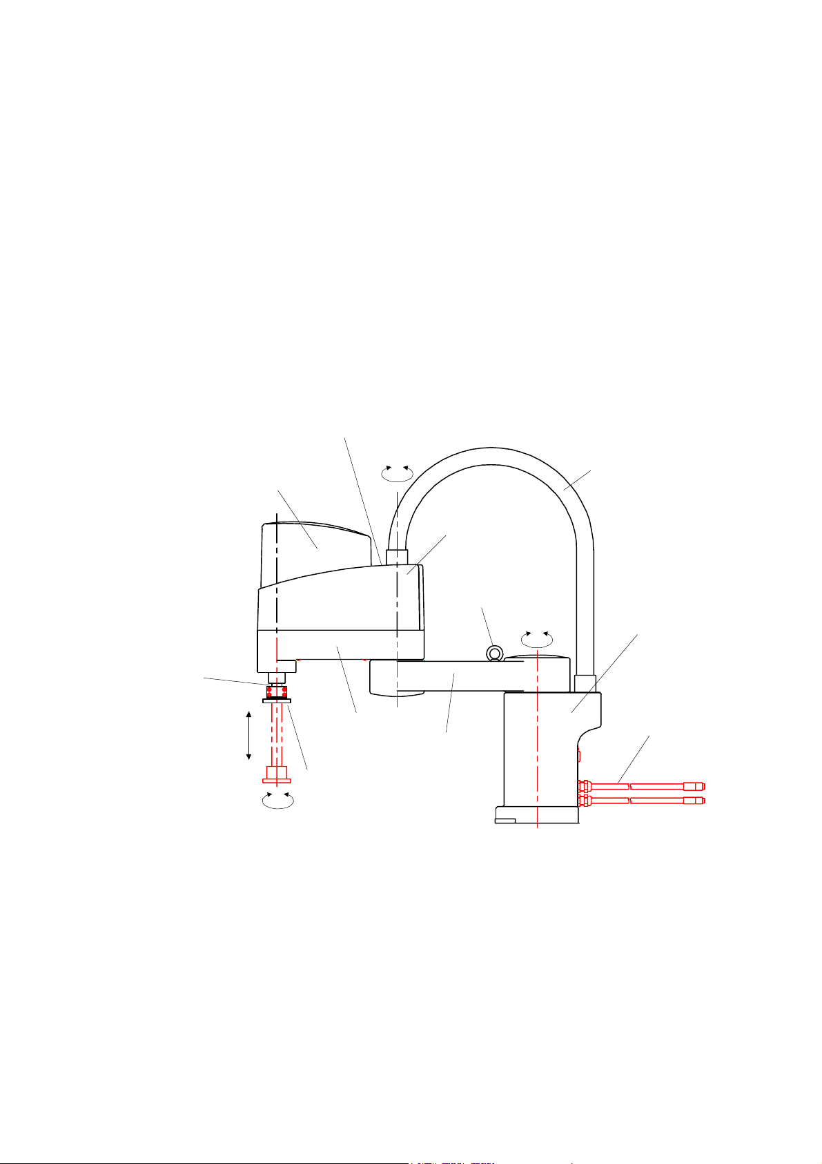
a) Names of the parts of the robot
The SR-H series is a group of robots having four degrees of freedom. Having
two degrees of freedom for positioning in a horizontal plane, one degree of
freedom for positioning in a vertical direction and one for the rotation of the tool
mounting flange, it is good at assembling and handling parts.
• Tool wiring
intake port
• Air fitting for user
Tool shaft
Axis 3
Arm 2 cover
Tool set flange
Axis 4
Arm 2
Axis 2
Connector for user
(built in the cover)
Eye bolt
Axis 1
Arm 1
Cable duct
Fixed base
Controller
connection cable
SR–654HSP
STE 58769
– 7 –
Page 8

b) Names of the parts of the controller
(1) Controller
⑮⑯
⑧⑨⑩⑪
⑦
SERVO POWER EMERGENCY
POWER
10AT
① ②
DC24V
C.P.
POWER
FAULT
EXT
INT
MANU
ONOFF
STARTSTOP
CYCLE STOP
BATTERY
⑫⑭
ALARM
⑰⑱
1) Main power switch
2) Circuit protector
3) J1 connector: connector for communication channel 1
4) J2 connector: connector for communication channel 2
J1
J2
PC
FDD
③
④
⑬
⑥
TP
⑤
5) TP connector: connector for connecting the teaching pendant
6) FDD connector: connector for connecting the floppy disk drive unit
7) Emergency switch
8) Servo power off switch
9) Servo power on switch
10) Stop switch: switch to stop automatic operation
11) Start switch: switch to start automatic operation
12) Cycle stop switch: switch to select the mode of performing 1 cycle of
automatic operation
13) PC connector: connector to connect a PC
STE 58769
– 8 –
Page 9

14) Master mode key switch: switch to select a robot mode
EXT: External automatic mode
INT: Internal automatic mode
MANU: Manual mode
15) Power lamp
16) Fault lamp: controller’s fault lamp
17) Buzzer: it sounds continuously when a fault is detected (since built in, it
is not visible from outside).
18) Battery alarm lamp: turns on or blinks when replacement of batteries is
necessary.
(2) Teaching pendant
17
21 1161514137652424
TOSHIBA
F1 F2 F3 F4 F5 F6
{}
Error
Ins Del
Esc
!;:,%^&,,()
QWERTYUIOP
Ctrl
ASDFGHJKL
Shift
ZXCVBNM
+/ <>?
Alt Exec
Utility
][
=.,*-
AUX
5500
SR-
Move
TEACH PEDANT
Servo ON
World
Work
Tool
Joint
Coordinate
High
X
Med
Low
Free
Inching
Jog
Y
Z
C
T
+-
+-
Teach
098Bs7654321
Speed
Control
Feed
Hold
8 9 10 3 11 12 18 19 20 22 23
1) Emergency stop switch
2) Function keys: Keys to select functions displayed at the
lowermost section of the liquid crystal display
3) Alphanumeric keys
4) Esc (escape) key: Key to cancel an inputted letter and operation
5) Insert key: Key to switch between the insert mode and the
replace mode
Insert mode: Inserts a letter anew between already inserted
letters.
Replace mode: A newly-inserted letter replaces one inputted
before.
STE 58769
– 9 –
Page 10

6) Delete key: Key to delete a letter on which the cursor is
placed.
7) Bs (backspace) key: Key to delete a letter just before the cursor.
8) Ctrl (control) key:
9) Shift key
10) Alt key
11) Run key
12) Cursor keys
13) Error display key: Key to display the description of an error on the
liquid crystal display
14) Utility key: Key to use auxiliary functions of the controller
15) Auxiliary signal key: Key to operate the hand and pneumatic- control
shaft of the robot
16) Move key: Key to move the robot to a position which is
taught to the robot
17) Guide coordinate key: Key to select a coordinate system along which
the robot is guided
18) Guide rate key: Key to select a traveling speed of the robot
when it is guided manually.
19) Guide mode key: To select a method for guiding the robot
Free: Mode to move the robot manually
Inching: Mode to move the robot by a certain amount
every time the guide key is pressed.
Jogging: Mode to move the robot while the guide key is
depressed
20) Feed hold key: Key to stop the operation of the robot
temporarily
21) Servo power on switch
22) Guide key: Key to guide the robot manually
23) Deadman switch:
24) Liquid crystal display
– 10 –
STE 58769
Page 11

c) Composition of robot system
Basic composition: Composed of the robot body, controller, teaching pendant,
and the FDD unit
SERVO POWER EMERGENCY
ONOFF
POWER
STARTSTOP
Robot
Basic robot
cable
FAULT
INT
MANU
EXT
CYCLE STOP
BATTERY
ALARM
Portable
(option)
Robot controller
CC24V
C.P.
POWER
10AT
SERVO POWER EMERGENCY
POWER
FAULT
INT
MANU
EXT
CYCLE STOP
FDD cable
ONOFF
STARTSTOP
BATTERY
ALARM
J1
J2
PC
FDD
TP cable
TP
FDD unit (option)
SR7000
FDD UNIT
Teach pendant (option)
TOSHIBA SR-5500
Operation
panel
Operating panel: Panel for starting and stopping automatic operation.
Detachable from the controller (optional), it is convenient
when the controller is stored under a rack. The CP cable
(cable between the operating panel and the controller) is
less than 30 m long.
– 11 –
STE 58769
Page 12

Teach pendant: Detachable from the connector and usable for multiple
robots commonly. Inserting a dummy plug (accessory)
allows automatic operation without the teaching pendant.
Body cable: 3 cables. Standard cable is 5 m long. Optional cables
can be 30 m at the maximum.
TP cable: Standard cable is 7 m long and a 30 m cable is available
as optional.
FDD cable: Standard cable is 2 m long and a 50 m cable is available
as optional.
– 12 –
STE 58769
Page 13

1.2 Coordinate System of the Robot
Coordinate systems include the world, base, tool and workpiece coordinate systems.
In the initial state, the world and workpiece coordinate systems match the base
coordinate system, and the tool coordinate system is a coordinate system whose
origin is a hand mounting flange. The world coordinate system, workpiece
coordinate system and the tool coordinate systems are set in accordance with work
and used. When coordinate systems are set, the robot is guided along the set
coordinate system and can be operated with the same position data to different tools.
There is no need for setting coordinate systems when the robot is guided to positions
where it actually operates and taught the positions. Setting coordinate systems
unnecessarily complicates position teaching operations. If there is no trouble, the
robot should be used at the initial condition without setting coordinate systems.
a) World coordinate system (absolute coordinate system)
Only one coordinate system for the whole of an work area where a robot is installed.
Generally, it is matched to the base coordinate system whose origin is the
cardinal point of installation of the robot.
b) Base coordinate system (machine coordinate system)
The coordinate system based on the center of the robot. Based on the origin posture
where each joint axis is zero. The base coordinate system is the natural
coordinate system determined from the structure of the robot.
c) Workpiece coordinate system (work coordinate system)
The coordinate system to be set for workpieces the robot work on and pallets. Different
workpiece coordinate systems are set for different workpieces.
d) Tool coordinate system
The coordinate system based on the hand mounting frange of the robot.
Depending on hands mounted on the robot, a tool coordinate system can be set
in a manner of matching it to the work point of the robot. The coordinate system
also moves with the operation of the robot.
Positions of the robot are expressed by X, Y, Z, C and T.
X, Y, Z: X, Y, Z coordinate values in an orthogonal coordinate system (in mm)
C: Rotation of the head of the tool (in degrees)
T: Rotation or direct advance of the 5th axis (in degrees or mm)
STE 58769
– 13 –
Page 14

A
A
Zt
0t
Xt
Yt
Tool coordinate system
ZB
Xw
Zw
Yw
0w
Wo rld c oordina te
system
Xw
Zw
0w
Wo rk c oordina te syste m
Yw
XB
0B
YB
Base coordinate system
Note) A plural number of work coordinate
system and tool coordinate system
can be set.
STE 58769
– 14 –
Page 15

1.3 External Input/Output Signals
A
a) External interface
Panel is separated (option).
Operation panel
7 m
Teach pendant
(option)
FDD
FDD unit
(option)
Personal
computer
For serial
communication
2 m
PC
J1
J2
C/P
TP
Controller
CN4
CN3
CN2
CN5
CN6
CN12
J3
CN13
CN1
Robot
body
5 m
External I/O and
operation I/O signals
For serial communication
TC200/terminal block I/O
Power supply
For end
effector
ir
Note: Cables for connecting the operating panel, teaching pendant, FDD unit, and
robot to the controller can be extended up to 30 m long at the maximum.
CN1: Power supply
CN2: Power cable for the main body of the robot
CN3: Robot body encoder wire
CN4: Robot body sensor signal, hand control signal
CN5: External operation input signal
CN6: External operation output signal
C/P: Signal wire for the operating panel (used to draw out the operating panel)
TP: Serial port for the teaching pendant
J1 to J3: Serial ports for users
CN12: External input output signals
CN13: RS485 port for connecting TC200/terminal board I/O
STE 58769
– 15 –
Page 16

a) Input output signals
1) External operation input signal (CN5)
External operation input signals are those to control the start and stop of the
robot controller SR7000 from external equipment such as a sequencer.
• "Stop," "Cycle operation mode," and "Low speed command" are b contact
point input. If this signal is not used, connect CN5-16, CN5-35, CN5-36 to
either of CN5-18, CN5-19 or CN5-37.
SR7000 robot
controller
(X8C1 printed
board)
CN5
1
20
2
21
3
22
4
23
5
24
6
25
7
26
8
27
9
28
10
29
11
30
12
31
13
32
14
33
15
34
16
35
17
36
18
37
19
Case
Customer's side
DI1
DI2
DI3
DI4
DI5
DI6
DI7
DI8
DI9
DI10
DI11
DI12
DI13
DI14
DI15
DI16
DI17
DI18
DI19
DI20
DI21
DI22
DI23
DI24
PG
PG
PG
Dsub-37S
Shown in parentheses is
the I/O port number.
(001)
(002)
(003)
(004)
(005)
(006)
(007)
(008)
(009)
(010)
(011)
(012) Digital
(013) Input signal
(014)
(015)
(016)
(017)
(018)
(019)
(020)
(021)
(022)
(023)
(024)
Strobe (245)
Program reset (236)
Step reset (237)
Cycle reset (238)
Output signal reset (239) external operation
Start (208) input signal
Stop (203)
Cycle operation mode (211)
Low speed command (212)
FG
Connection of external input signal wire
– 16 –
STE 58769
Page 17

2) External operation output signal (CN6)
A
3
A
External operation output signals are those which output operating conditions
of the robot controller SR7000.
• When input signals such as "servo off" and "emergency stop" are open, "servo
on" is not feasible.
• User output is open collector output of capacity of DC 24 V, 100 mA.
• Output signals "servo on" and "emergency stop" are 2 output non voltage
output.
• Use the 24 V power supply at a total capacity of 2 A or less including CN12.
CN6
SR7000
Robot controller
(X8C2 printed board)
20
21
22
23
24
25
26
27
28
10
29
11
30
12
31
13
32
14
33
15
34
16
35
17
36
18
37
19
Case
FG
User side
1
2
3
4
5
6
7
8
9
17JE-23370-02(D8A)
(Dsub-37P)
DO1
DO2
DO3
DO4
DO5
DO6
DO7
DO8
DO9
DO10
DO11
DO12
DO13
DO14
DO15
DO16
P24V
P24V
P24V
Signal name in
parenthses.
(1)
(2)
(3)
(4)
(5)
(6)
(7)
(8)
(9)
(10)
(11)
(12)
(13)
(14)
(15)
(16)
Manual mode ON (222)
External automatic mode ON (22
Operation ready (221)
Fault (216)
Cycle finish (219)
Low speed mode ON (218)
During servo ON.
Emergency stop ON
P24V
Servo ON
Servo OFF
Emergency stop
Digital
output signals
cknowledge (217)
utomatic mode ON (220)
In total, 2 A or less,
including CN12.
Connection of external output signal wire
STE 58769
– 17 –
Page 18

3) External output signals (CN12)
External input output signals are those which input and output the operating
condition of the robot controller SR7000.
• User output is open collector output with a capacity of DC 24 V, 100 mA.
• Use the 24 V power supply at 2A or less including CN6.
CN12
SR7000
Robot controller
(X8C1) printed board
User side
1
14
2
15
3
16
4
17
P24V
5
P24V
18
6
19
7
20
8
21
9
22
10
23
11
24
12
25
13
Case
17JE-23250-02(D8A)
(Dsub-25P)
DI25
DI26
DI27
DI28
DI29
DI30
DI31
DI32
DO17
DO18
DO19
DO20
DO21
DO22
DO23
DO24
PG
PG
Signal name in
parentheses.
(25)
(26)
(27)
(28) Digital
(29) input signals
(30)
(31)
(32)
2 A or less in total (including CN6)
(17)
(18)
(19)
(20) Digital
(21) output signals
(22)
(23)
(24)
FG
Connection of external I/O signal wire
– 18 –
STE 58769
Page 19

4) Auxiliary input and output signals
DC 24 V wires, including five for input signals from sensors and 4 for control
output signals to electromagnetic valves, are routed to the second arm of the
robot, and allow the opening and closing of the hand and the monitoring of
on/off of sensors.
• Output is open collector output and has a capacity of DC24V, 1 A.
• Signal numbers of auxiliary input signals are as given below.
Input: Signal number 220 ··· GRP1 OPN Output: Signal number 214 ··· GRP1
219 ··· GRP1 CLS 213 ··· GRP1
218 ··· GRP2 OPN 212 ··· GRP2
217 ··· GRP2 CLS 211 ··· GRP2
216 ··· WORK
Remove the upper cover of the second
arm and connect your connectors to the
JOES
JOFS
JOFP
JOFS
CN4
JOEP
JOES
two connectors JOES, JOFS inside it.
To control the hand with your sequencer,
remove the connectors and connect a
separate cable from the outside.
– 19 –
STE 58769
Page 20

JOES SM connector 7 poles
Signal
Pin
name
1
GRP1 OPN
2
GRP1 CLS
3
GRP2 OPN
4
GRP2 CLS
5
6
7
WORK
PGND
Shield
Sensor
Color
Yellow
White (yellow)
Green
White (green)
Red
White (red)
Green
JOEP SM connector 7 poles JOES
Signal
Color
Yellow
White (yellow)
Green
White (green)
Red
White (red)
Green
Pin
1
2
3
4
5
6
7
name
GRP1 OPN
GRP1 CLS
GRP2 OPN
GRP2 CLS
WORK
PGND
Shield
Green
Yellow
Brown
Blue
Gray
Green
Color
Red
JOFS SM connector 7 poles
Signal
Pin
name
1
GRP1
2
GRP1
3
P24
GRP2
4
5
GRP2
6
Solenoid valve, etc.
P24
Color
Purple
White
Blue
Brown
Yellow
Brown
JOFP SM connector 7 poles JOFS
Color
Purple
White (purple)
Blue
Brown
Yellow
Brown
Pin
1
2
3
4
5
6
Signal
name
GRP1
GRP1
P24
GRP2
GRP2
P24
Orange
Purple
Pink
Light green
Light blue
Black/white
Color
Connector type
JOES
JOEP
JOFS
JOFP
---- SMP–07V–BC (J.S.T Corporation)
---- SMR–07V–B (J.S.T Corporation)
---- SMR–06V–BC (J.S.T Corporation)
---- SMR–06V–B (J.S.T Corporation)
Provided by the customer.
Provided by the customer.
5) Serial communication
The SR7000 controller is furnished with hardware and software for
communication with external equipment as standard components.
Controller
• Port: there are four ports including one exclusively used for the teaching
pendant.
J1 and J2 are switchable. Switching is made by operation mode or robot
language instructions.
Equipment to be connected to J1 to J3 is registered in the system
configuration file.
Teach pendant
J1
J3 J1, J3: RS–232C
J2: RS–232C or RS422
J2
Front Controller Back
STE 58769
– 20 –
Page 21

1.4 Mode System
Operation modes include the following.
Master mode: Switching is made by the key switch on the operating panel.
Sub mode: Switching is made by specifying the teaching pendant or system
configuration file.
Master mode Sub mode Description
External automatic Communication mode Operation of the robot by serial
communication.
I/O mode Operation of the robot by external
operation signals.
Internal automatic Operation of the robot from the controller
operating panel.
Manual Test run Running the program at lower speed.
Edit Editing of programs, teaching of
positions, editing of data.
File manipulation Saving, reading and copying of files.
Teaching of joint limits, setting of
coordinates.
Computer
(Internal automatic
operation)
(External automatic
operation)
External operation box
(Manual
operation)
Operation panel
SERVO POWER EMERGENCY
ONOFF
POWER
STARTSTOP
FAULT
INT
EXT
Teach pendant
TOSHIBA SR-5500
BATTERY
ALARM
MANU
CYCLE STOP
– 21 –
STE 58769
Page 22

1.5 File
a) File names
File: Unit of storage for a program, etc.
A maximum of 248 program files used by a user can be stored.
However, memory is limited. 3,000 program steps and 150 points of
position data are a rule of thumb for measuring the size of a file.
File name: “$$$$$$$$.$$$”
Extensions (omission is allowed.)
Up to three alphanumerics
File name
Up to eight alphanumerics (headed by an English letter)
Drive name: Suffixed to a file name and specifies the location of the file.
"A": FDD (floppy disk)
"R": RAM drive (controller memory)
If the drive name is omitted, it is regarded as a file in the RAM
drive.
Floppy disks must be 3.5-inch 2HD. For the SR–5500, 2DD type is used.
b) Types of files
1) Program file “$$$$$$$$.$$$”
File storing robot language programs and position data
2) Batch file “$$$$$$$$.BAT”
File to run multiple commands together
Operations which are performed frequently are registered in the batch file and
run.
To run a batch file, enter the file name of the batch file as a command.
(entering the extension "BAT" is not needed)
Example: "FLOAD.BAT"
LOAD PROG1
LOAD PROG2
LOAD PROG3
LOAD PROG4
→ When FLOAD is run, PROG1 to PROG4 are read out
to the RAM drive.
STE 58769
– 22 –
Page 23

3) System configuration file "CONSTRC.SYS."
File storing an optional configuration of the robot, equipment connected to the
serial port, settings of signals used for selecting files by external signals.
(When necessary, users may change the content. After change, save the
change in a floppy disk).
4) Automatic execution file "AUTOSTR.BAT"
Batch file which is run automatically when the power is turned on (when
necessary, users may change the content. Store it on a floppy disk after
change)
5) System parameter file "SYSTEM.PAR"
File storing control parameters of the robot
6) User parameter file "USER.PAR"
File storing the home position and soft limits of the robot.
When these settings are changed, the content of the file is changed
automatically. (After changed, save the change on a floppy disk)
7) System file "SVPMTX.SYS", "MCPMTX.SYS"
File storing a system to operate the robot.
It is stored only on a system disk. (LOAD, SAVE, COPY commands can not
be used.)
8) Message file "ALARM.MES"
Error messages to be display on the teaching pendant are stored in the file.
They are read out only by the COPY command.
9) External selection file "EXTRNSEL.SYS"
File to be selected by external signals are stored in the file.
10) Library file "SCOL.LIB"
Some instruction words of the robot language are stored in the file.
Sub programs created in the library file can be run in all files.
– 23 –
STE 58769
 Loading...