

Page 1

FILE NO. 020-200420
REVISION 1
SERVICE MANUAL
Projection Television
46HM94
52HM94
62HM94
DOCUMENT CREATED IN JAPAN, Oct., 2004
Page 2

TABLE OF CONTENTS
CHAPTER 1 GENERAL ADJUSTMENTS
SAFETY INSTRUCTIONS .............................................................................................................................................. 3
SERVICE MODE ............................................................................................................................................................ 4
CHAPTER 2
SPECIFIC INFORMATIONS
SETTING & ADJUSTING DATA ...................................................................................................................................... 7
LAMP UNIT REPLACEMENT ......................................................................................................................................... 8
LIGHT ENGINE REPLACEMANT.................................................................................................................................
PARTS REPLACEMENT IN LIGHT ENGINE...............................................................................................................
EXPLODED VIEW ........................................................................................................................................ ................ 15
MECHANICAL DISASSEMBLY .................................................................................................................................... 16
CHASSIS REPLACEMENT PARTS LIST ..................................................................................................................... 17
PC BOARDS TOP AND BOTTOM VIEW ..................................................................................................................... 26
TERMINAL VIEW OF TRANSISTORS ......................................................................................................................... 44
CIRCUIT BLOCK DIAGRAM ........................................................................................................................................ 48
SPECIFICATIONS .................................................................................................................................................... END
APPENDIX:
CIRCUIT DIAGRAM
11
13
-
2
-
Page 3

CHAPTER 1 GENERAL ADJUSTMENTS
SAFETY INSTRUCTIONS
SAFETY PRECAUTION
WARNING: Service should not be attempted by anyone unfamiliar with the necessary precautions on this receiver. The following
are the necessary precautions to be observed before servicing this chassis.
1. An isolation transformer should be connected in the power line between the receiver and the AC line before any service is
performed on the receiver.
2. When the replacing a chassis in the cabinet, always be certain that all the prospective devices are put back in place, such
as; non-metallic control knobs,insulating covers, shields, isolation resistor-capacitor network etc.
PRODUCT SAFETY NOTICE
Many electrical and mechanical parts in this chassis have special safety-related characteristics. These characteristics are
often passed unnoticed by a visual inspection and the protection afforded by them cannot necessarily be obtained by using
replacement components rated for higher voltage, wattage, etc. Replacement parts which have these special safety characteristics are identified in this manual and its supplements; electrical components having such features are identified by the
international hazard symbols on the schematic diagram and the parts list.
Before replacing any of these components, read the parts list in this manual carefully. The use of substitute replacement
parts which do not have the same safety character istics as specified in the parts list may create shock, fire, or other hazards.
-
3
-
Page 4
SERVICE MODE
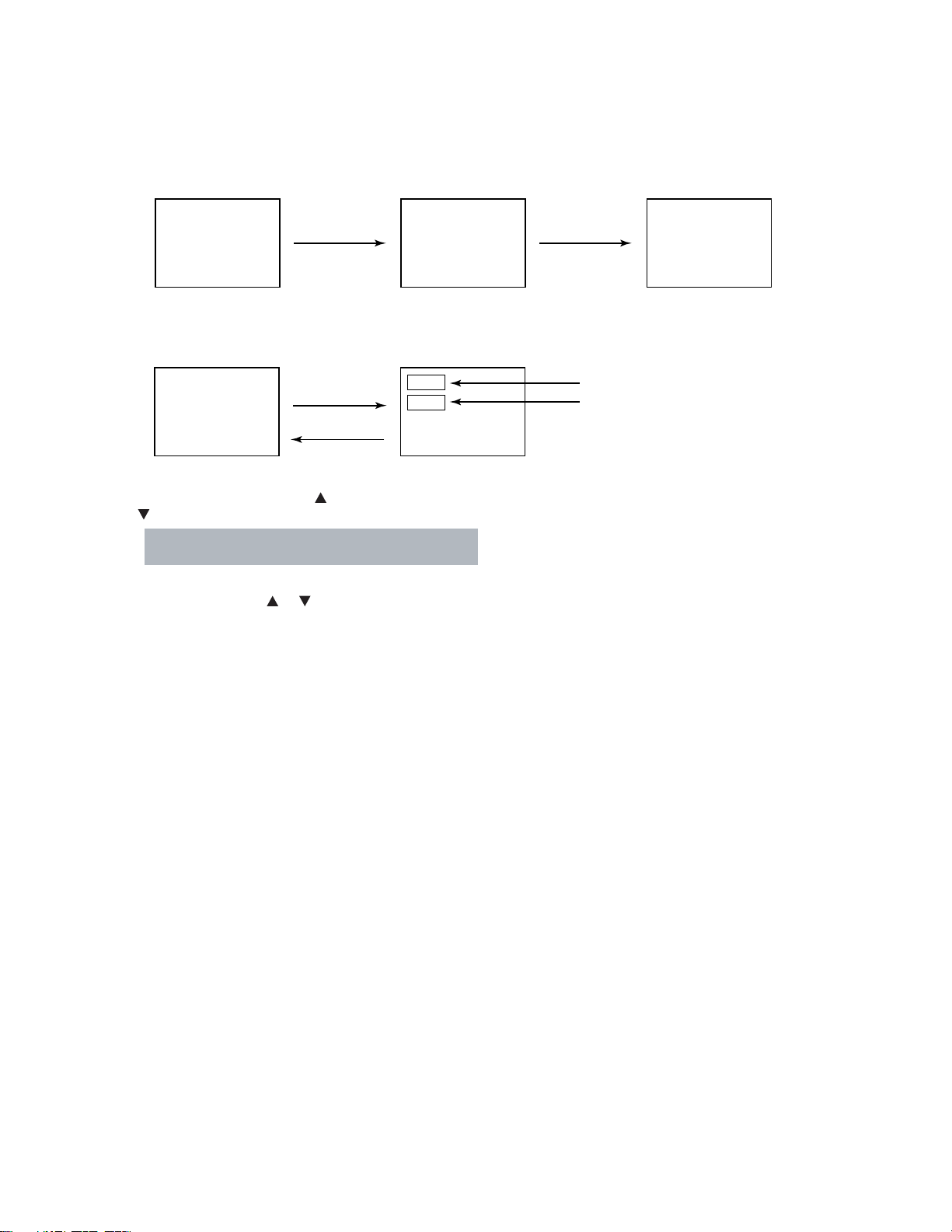
1. ENTERING TO SERVICE MODE
1) Press MUTE button twice
on Remote Control.
MUTE
2) Press MUTE button
again to keep pressing.
2. DISPLAYING THE ADJUSTMENT MENU
1) Press MENU button on TV.
Service mode
S
Press
Press
Adjustment mode
3. SELECTING THE ADJUSTING ITEMS
1) Every pressing of CHANNEL button in the service mode changes the adjustment items in the order of table-2.
( button for reverse order)
Refer to table-1 for preset data of adjustment mode.
(See SETTING & ADJUSTING DATA on page 7)
3) While pressing the MUTE button,
press MENU button on TV set.
S
(Service mode display)
Item
Data
4. ADJUSTING THE DATA
1) Pressing of VOLUME or button will change the value of data in the range from 00H to FFH. The variable range
depends on the adjusting item.
5. EXIT FROM SERVICE MODE
1) Pressing POWER button to turn off the TV once.
-
4
-
Page 5
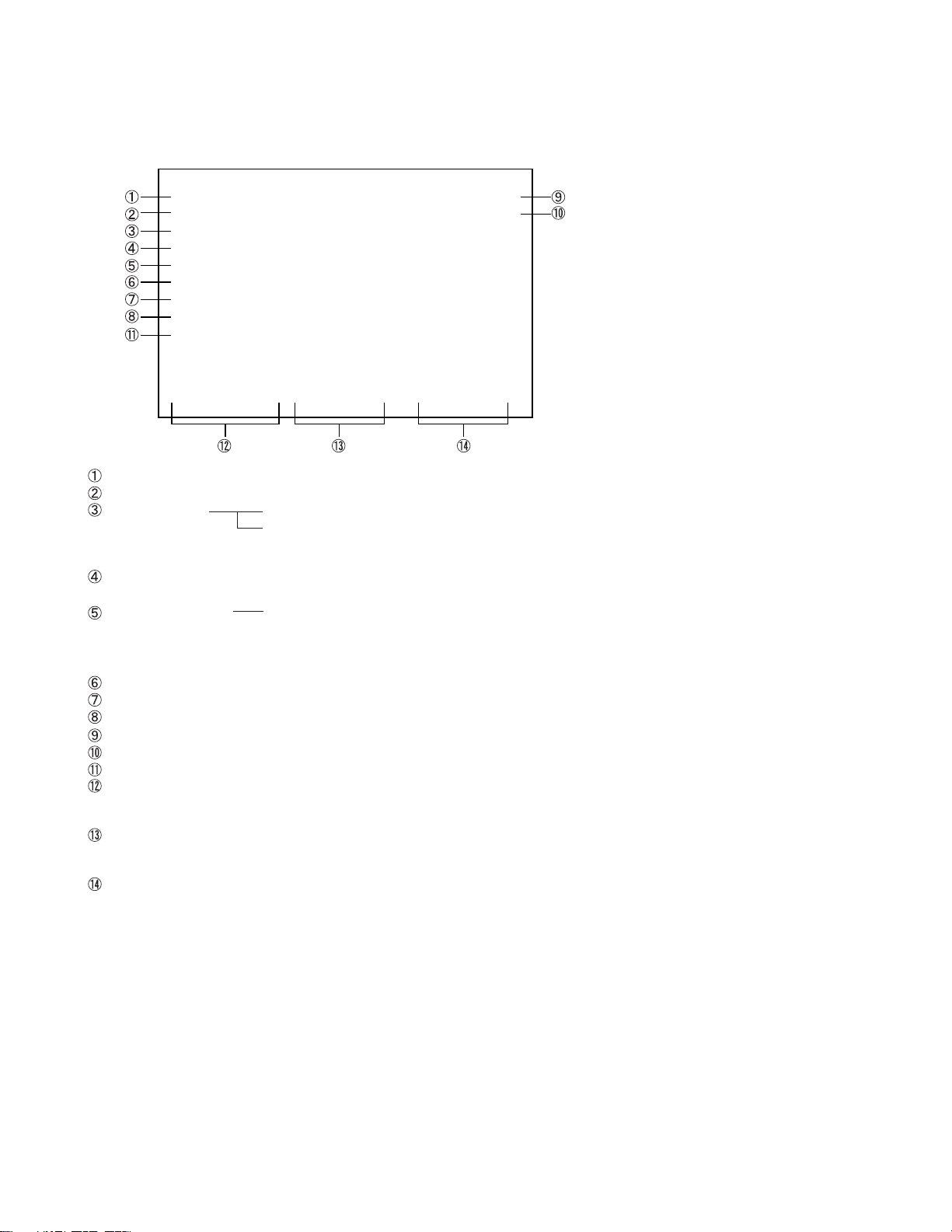
6. SELF DIAGNOSTIC FUNCTION
1) Press “9” button on Remote Control during display of adjustment menu in the service mode.
The diagnosis will begin to check if interface among IC’s are executed properly.
2) During diagnosis, the following displays are shown.
SELF CHECK
NO. 23 * * * * * *
POWER : 000
BUS LINE : OK
BUS CONT : OK
BLOCK : MAIN SUB
SET ID : 80
E2P VER : 08
OPT1 : 00 OPT2 : A0
SW VER : DLE May 13 2004 17:**:**
HDMI
NO ********
ERR CDDE : 00
BEP
SW VER : 42
E2R VER : 02
Thermo1 : +51
Thermo2 : +50
TIME
TV : ******
LAMP :
****
Part number of microprocessor (IC609)
Operation number of protection circuit (The number of times of the power supply OFF by fan stop) . . . . “000” is normal.
BUS line check “OK” ................... Normal
“SCL-GND” or “NG” ........... SCL-GND short circuit
“SDA-GND” or “NG” ........... SDA-GND short circuit
“SCL-SDA” or “NG” ............ SCL-SDA short circuit
BUS line ACK (acknowledge) check
“OK” ................... Normal
Sync. signal check Green display ..... Normal
Red display ........ NG
MAIN ........ Main sync
SUB .......... Sub sync (when turn on the PIP)
ID code for TV Set
Version of "EEP"
Data for "OPT"
Temperature of DMD
Temperature of the color wheel neighborhood
Software version history
HDMI Software
NO ***** .....Serial No.
ERR CODE .....Error Code
BEP Software Version
SW VER : **..... Version
E2P VER : ** EEP ROM Version
Use time
TV .....TV set on time (hour)
LAMP.....LAMP set on time (hour)
(It may shift from TV set on time.)
-
5
-
Page 6
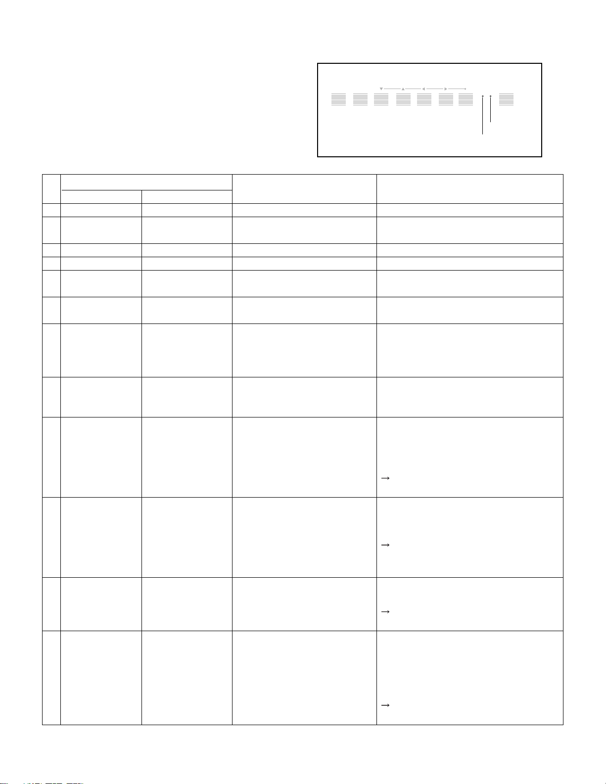
7. LED indicationsn
The green and red LED lights on the TV control touchpad
(on the lower right corner of the TV screen)
indicate the TV's current status, as follows:
.
Green ON = Control touchpad being pressed.
.
Red ON = Power ON.
.
Green and/or Red blinking
(see table below for condition and solution).
Control touchpad on TV front
MENUVOLUMECHANNELEXITTV/VIDEO POWER
Red indicator
Green indicator
LED Indication
Red LED Green LED
1
OFF OFF
2
OFF OFF
3
ON (Solid) OFF
4
ON (Solid) ON (Solid)
5
OFF Blinks
(1sec. intervals)
6
ON Blinks
(Solid) (0.3sec. intervals)
7
Blinks ON
(0.5sec. intervals) (Solid)
8
Blinks Blinks
(1sec. intervals) (1sec. intervals)
9
Blinks OFF
(0.5sec. intervals)
10
Blinks OFF
(1sec. intervals)
11
Blinks OFF
(3times)
12
Blinks Blinks
(3times) (3times)
Condition
Power supply OFF. (AC)
Power supply OFF. (Standby)
(North America)
Power supply ON.
Touched the touchpad
Lamp LPS mode
The lamp is not working properly.
The lamp unit door is not seated
properly. (U)
The lamp is not working properly
after the third automatic reset (see
item #7). (U)
FAN (Light engine unit) has
stopped.
BUS line is damaged
The collar wheel has stopped.
Temperature rises abnormally.
(U) is restoration by the user.
Solution
The TV automatically will try to reset itself
three times.
Turn the POWER OFF and unplug the power
cord. Review “How to replace the lamp unit”
on pages 13-15 to ensure that the lamp unit
door is installed securely.
Turn the POWER OFF and then ON again. If
the problem persists, replace“the lamp unit
(see pages 13-15).
• Is the output voltage of the supply voltage
regulator for the FAN in the power circuit
normal?
• Has dust accumulated in the FAN?
If the output voltage is not abnormal,
replace the faulty FAN with a new one.
• Check the faulty device through the self
diagnostics function under SERVICE mode.
• Does BUS line (SOL, SDA) work normally?
If the BUS line is under abnormal
conditions, replace the faulty device with
a new one.
• Is the output voltage of the power supply
circuit normal?
If the output voltage is normal, replace the
engine with a new one.
• Is the ventilating hole in the set (exhaust
slot on the rear) blocked or covered?
• Is FAN rotating normally?
• Has dust accumulated in the ventilating
hole?
If no abnormally conditions are found,
replace the engine with a new one.
-
6
-
Page 7
CHAPTER 2 SPECIFIC INFORMATIONS
SETTING & ADJUSTING DATA
SERVICE MODE
ADJUSTING ITEMS AND DATA IN THE SERVICE MODE:
Item Name of adjustment
RCUT R CUT OFF
GCUT G CUTOFF
BCUT B CUT OFF
GDRV G DRIVE
BDRV B DRIVE
BRTC BRIGHT CENTER
SCNT
COLC COLOR CENTER
UVTT BASE BAND TINT
CNTX SUB CONTRAST MAX
HPOS H-POSITION (PAL/DFS)
VPOS
CWDH
CWDL
DMDB DMD BIAS
OPT1 TV SET OPTION
OPT2 TV SET OPTION
Note:
The image system data of RCUT-CNTX is different by each image format.
The NTSC value is indicated in the table.
SUB CONTRAST FOR TV
V-POSITION DC SHIFT (PAL/DFS)
COLOR WHEEL DELAY (HIGH)
COLOR WHEEL DELAY (LOW)
Preset Data
80H
80H
80H
40H
40H
80H
10H
4BH
43H
7FH
00H
00H
00H
FAH
03H
04H
A0H
Table-1
Item Name of adjustment
TVOP TV OPTION
PLLW0 PLL WAIT TIME
PLLW1 PLL WAIT TIME
PLLW2 PLL WAIT TIME
PLLW3 PLL WAIT TIME
PLLW4 PLL WAIT TIME
PLLW5 PLL WAIT TIME
V01 VOLUME (DATA)
V25 VOLUME (DATA)
V50 VOLUME (DATA)
V75 VOLUME (DATA)
V100 VOLUME (DATA)
MODH MODUS DATA HIGH
MODL MODUS DATA LOW
PRES FMAM PRESCALE
SCTH
SCTL
VOLUME SCART OPTION HIGH
VOLUME SCART OPTION LOW
Preset Data
40H
14H
03H
0FH
05H
14H
04H
23H
4AH
63H
6FH
23H
20H
91H
24H
73H
01H
-
7
-
Page 8

LAMP UNIT REPLACEMENT
Cautions when replacing LAMP UNIT
The light source for this TV is a mercury lamp with internal atmospheric
pressure that increases during use. The lamp has a limited service life
that varies depending on user settings. If you use the lamp beyond its
service life:
.
you may notice a reduction in the colors and/or brightness of the picture; and
.
the strength of the quartz glass in the lamp will be reduced and the
lamp may rupture (often making a loud noise when this happens). If
the lamp reputres, the TV will operate until the lamp unit is replaced.
Note: The lamp unit is designed so broken lamp glass remains se-
curely inside the lamp unit.
CAUTION: Always handle the lamp unit with care.
The lamp unit in this TV was designed for safe replacement by consumers; however, if the lamp unit is subjected to intentional abuse (such as excessive mechanical abuse or handling by
children or pets), the unit may break, exposing edges or pinch points.
When to replace the lamp unit
You should replace the lamp unit:
.
if the picture darkens and/or colors fade;
.
if the lamp does not light; or
.
If you hear a loud noise and the picture goes black, which may indicate a lamp rupture.
-
8
-
Page 9
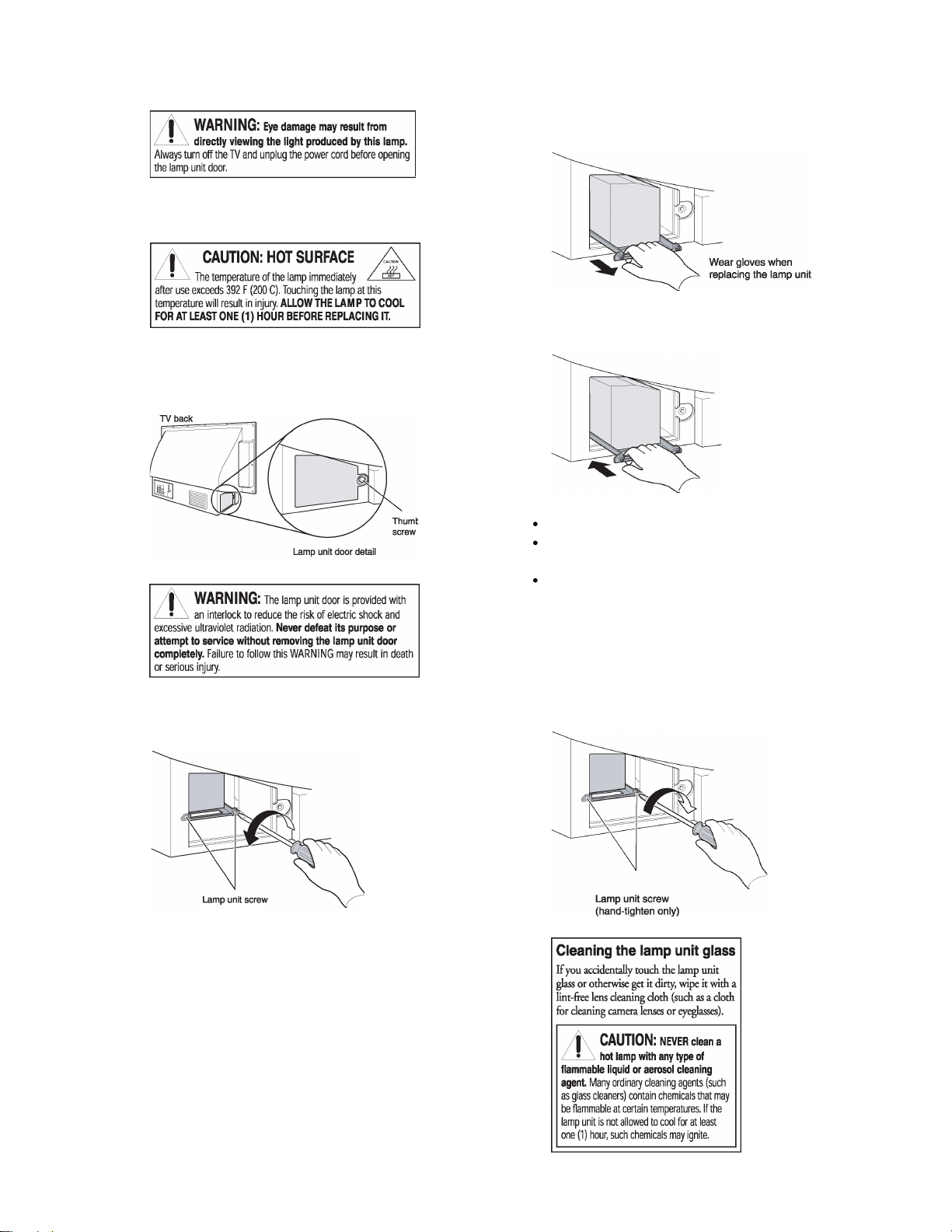
1. Turn off the TV and unplug the power cord.
2. STOP! Allow the lamp to cool for at least one (1) hour
before replacing it.
3. On the back of the TV, loosen the thumb screw (by hand)
on the lamp unit door, and then remove the lamp unit
door.
5. Grasp the lamp unit handle and gently pull the lamp unit
straight out of the TV. Set the old lamp unit aside.
6. Carefully insert the new lamp unit straight into the TV
until it is fully seated.
Note :
Never subject the lamp unit to excessive shock.
Never touch the lamp unit glass or otherwise get it
dirty.
Doing so may affect the image quality and reduce
the service life of the lamp. See “Cleaning the lamp
unit glass” below.
4. Using a manual screwdriver, loosen two screws on the
lamp unit.
7. Using a manual screwdriver, tighten two lamp unit
screws.
Note:Hand-tighten only. Do not use an electric screwdriver.
-
9
-
Page 10
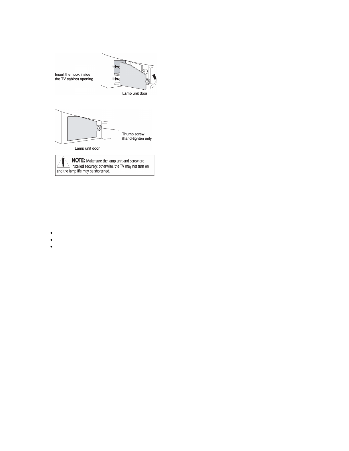
8. Reattach the lamp unit door, making sure to insert the
hook on the left side of the lamp unit door inside the
opening in the TV cabinet.
9. Replace the thumb screw and hand-tighten.
10. Plug in the power cord and turn on the TV. After the
initial warmup period (which may take up to 45 seconds
for full picture brightness), the TV should operate normally. If any of the following conditions exist, turn off the
TV, unplug the power cord, and repeat steps 1-9 to ensure that the lamp unit and lamp unit door are installed
correctly:
No picture
Dark picture
TV will not turn on
-
10
-
Page 11
LIGHT ENGINE REPLACEMENT
Cautions when replacing LIGHT ENGINE
LIGHT ENGINE is a heart of TV which emits high heat.
Make sure to replace it after turning off the TV and wait
for sufficient cool down. (More than one hour is recommended.)
Do not add any impact during replacement; otherwise,
some parts may be damaged.
Do not touch any optical lens. Adhesion of dirt may
deteriorate its performance.
Do not loosen any screw other than those to be removed
for adjustment or replacement.
LIGHT ENGINE emits ultraviolet rays when the TV is
ON. Make sure to be careful.
1. Replacement of Light Engine Unit
1-1. When Light Engine Unit is replaced with a new one, the
adjustment is required. Adjusted values are described
in bar code, and the values of bar code must be converted to the adjusted values for the setup.
There are 2 types of bar code.
1-2. Adjustment is made by service mode. The adjusting
items consist of CWDL, CWDH and DMDB.
CWDL CWDH
When CW delay number of the data bar code is 0450:
0450 indicates 450 45.0
Double 45.0 to form hexadecimal number (HEX).
45.0 x 2=90 5A (hexadecimal)
The adjusted value becomes “5A” for CWDL and “00”
for CWDH.
If hexadecimal number forms 3 or 4 digits, the latter 2
digits indicate CWDL while the first 2 digits indicate
CWDH.
(For 3 digits, CWDH=0*)
Note:
For converting decimal number to hexadecimal number, see the conversion table on the next page.
Serial bar code
Data bar code
Serial bar code
Ex. 52A000A111111
Inch size
Data bar code (CW: color wheel)
Ex. A111111B1111
Serial numbers
CWdelay number: 4digits
DMD bias value
Substrate serial numbers
DMDB
Read DMD bias value described in alphabet from the
data bar code. In service mode, DMDB value is converted and fixed by the following table.
DMD value in bar
code
B00
C01
D02
E03
F04
Refer to Service Mode for adjusting the service mode.
Adjusted value
(Hex)
-
11
-
Page 12

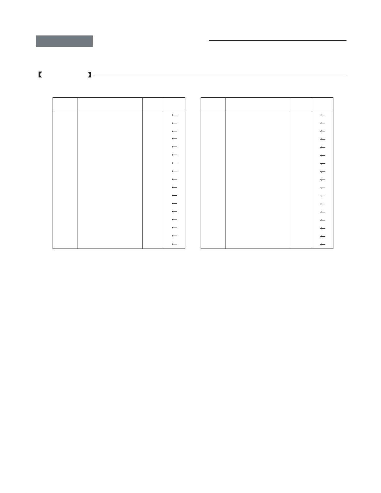
Conversion Table for Decimal and Hexadecimal Numbers
CW delay number CWDH CWDL
0000 00 00
0005 00 01
0010 00 02
0015 00 03
0020 00 04
0025 00 05
0030 00 06
0035 00 07
0040 00 08
0045 00 09
0050 00 0A
0055 00 0B
0060 00 0C
0065 00 0D
0070 00 0E
0075 00 0F
0080 00 10
0085 00 11
0090 00 12
0095 00 13
0100 00 14
0105 00 15
0110 00 16
0115 00 17
0120 00 18
0125 00 19
0130 00 1A
0135 00 1B
0140 00 1C
0145 00 1D
0150 00 1E
0155 00 1F
0160 00 20
0165 00 21
0170 00 22
0175 00 23
0180 00 24
0185 00 25
0190 00 26
0195 00 27
0200 00 28
0205 00 29
0210 00 2A
0215 00 2B
0220 00 2C
0225 00 2D
0230 00 2E
0235 00 2F
0240 00 30
0245 00 31
0250 00 32
0255 00 33
0260 00 34
0265 00 35
0270 00 36
0275 00 37
0280 00 38
0285 00 39
0290 00 3A
0295 00 3B
0300 00 3C
0305 00 3D
0310 00 3E
0315 00 3F
0320 00 40
0325 00 41
0330 00 42
0335 00 43
0340 00 44
0345 00 45
0350 00 46
0355 00 47
0360 00 48
0365 00 49
0370 00 4A
CW delay number CWDH CWDL
0375 00 4B
0380 00 4C
0385 00 4D
0390 00 4E
0395 00 4F
0400 00 50
0405 00 51
0410 00 52
0415 00 53
0420 00 54
0425 00 55
0430 00 56
0435 00 57
0440 00 58
0445 00 59
0450 00 5A
0455 00 5B
0460 00 5C
0465 00 5D
0470 00 5E
0475 00 5F
0480 00 60
0485 00 61
0490 00 62
0495 00 63
0500 00 64
0505 00 65
0510 00 66
0515 00 67
0520 00 68
0525 00 69
0530 00 6A
0535 00 6B
0540 00 6C
0545 00 6D
0550 00 6E
0555 00 6F
0560 00 70
0565 00 71
0570 00 72
0575 00 73
0580 00 74
0585 00 75
0590 00 76
0595 00 77
0600 00 78
0605 00 79
0610 00 7A
0615 00 7B
0620 00 7C
0625 00 7D
0630 00 7E
0635 00 7F
0640 00 80
0645 00 81
0650 00 82
0655 00 83
0660 00 84
0665 00 85
0670 00 86
0675 00 87
0680 00 88
0685 00 89
0690 00 8A
0695 00 8B
0700 00 8C
0705 00 8D
0710 00 8E
0715 00 8F
0720 00 90
0725 00 91
0730 00 92
0735 00 93
0740 00 94
0745 00 95
CW delay number CWDH CWDL
0750 00 96
0755 00 97
0760 00 98
0765 00 99
0770 00 9A
0775 00 9B
0780 00 9C
0785 00 9D
0790 00 9E
0795 00 9F
0800 00 A0
0805 00 A1
0810 00 A2
0815 00 A3
0820 00 A4
0825 00 A5
0830 00 A6
0835 00 A7
0840 00 A8
0845 00 A9
0850 00 AA
0855 00 AB
0860 00 AC
0865 00 AD
0870 00 AE
0875 00 AF
0880 00 B0
0885 00 B1
0890 00 B2
0895 00 B3
0900 00 B4
0905 00 B5
0910 00 B6
0915 00 B7
0920 00 B8
0925 00 B9
0930 00 BA
0935 00 BB
0940 00 BC
0945 00 BD
0950 00 BE
0955 00 BF
0960 00 C0
0965 00 C1
0970 00 C2
0975 00 C3
0980 00 C4
0985 00 C5
0990 00 C6
0995 00 C7
1000 00 C8
1005 00 C9
1010 00 CA
1015 00 CB
1020 00 CC
1025 00 CD
1030 00 CE
1035 00 CF
1040 00 D0
1045 00 D1
1050 00 D2
1055 00 D3
1060 00 D4
1065 00 D5
1070 00 D6
1075 00 D7
1080 00 D8
1085 00 D9
1090 00 DA
1095 00 DB
1100 00 DC
1105 00 DD
1110 00 DE
1115 00 DF
1120 00 E0
CW delay number CWDH CWDL
1125 00 E1
1130 00 E2
1135 00 E3
1140 00 E4
1145 00 E5
1150 00 E6
1155 00 E7
1160 00 E8
1165 00 E9
1170 00 EA
1175 00 EB
1180 00 EC
1185 00 ED
1190 00 EE
1195 00 EF
1200 00 F0
1205 00 F1
1210 00 F2
1215 00 F3
1220 00 F4
1225 00 F5
1230 00 F6
1235 00 F7
1240 00 F8
1245 00 F9
1250 00 FA
1255 00 FB
1260 00 FC
1265 00 FD
1270 00 FE
1275 00 FF
1280 01 00
1285 01 01
1290 01 02
1295 01 03
1300 01 04
1305 01 05
1310 01 06
1315 01 07
1320 01 08
1325 01 09
1330 01 0A
1335 01 0B
1340 01 0C
1345 01 0D
1350 01 0E
1355 01 0F
1360 01 10
1365 01 11
1370 01 12
1375 01 13
1380 01 14
1385 01 15
1390 01 16
1395 01 17
1400 01 18
1405 01 19
1410 01 1A
1415 01 1B
1420 01 1C
1425 01 1D
1430 01 1E
1435 01 1F
1440 01 20
1445 01 21
1450 01 22
1455 01 23
1460 01 24
1465 01 25
1470 01 26
1475 01 27
1480 01 28
1485 01 29
1490 01 2A
1495 01 2B
CW delay number CWDH CWDL
1500 01 2C
1505 01 2D
1510 01 2E
1515 01 2F
1520 01 30
1525 01 31
1530 01 32
1535 01 33
1540 01 34
1545 01 35
1550 01 36
1555 01 37
1560 01 38
1565 01 39
1570 01 3A
1575 01 3B
1580 01 3C
1585 01 3D
1590 01 3E
1595 01 3F
1600 01 40
1605 01 41
1610 01 42
1615 01 43
1620 01 44
1625 01 45
1630 01 46
1635 01 47
1640 01 48
1645 01 49
1650 01 4A
1655 01 4B
1660 01 4C
1665 01 4D
1670 01 4E
1675 01 4F
1680 01 50
1685 01 51
1690 01 52
1695 01 53
1700 01 54
1705 01 55
1710 01 56
1715 01 57
1720 01 58
1725 01 59
1730 01 5A
1735 01 5B
1740 01 5C
1745 01 5D
1750 01 5E
1755 01 5F
1760 01 60
1765 01 61
1770 01 62
1775 01 63
1780 01 64
1785 01 65
1790 01 66
1795 01 67
-
12
-
Page 13

PARTS REPLACEMENT IN LIGHT ENGINE
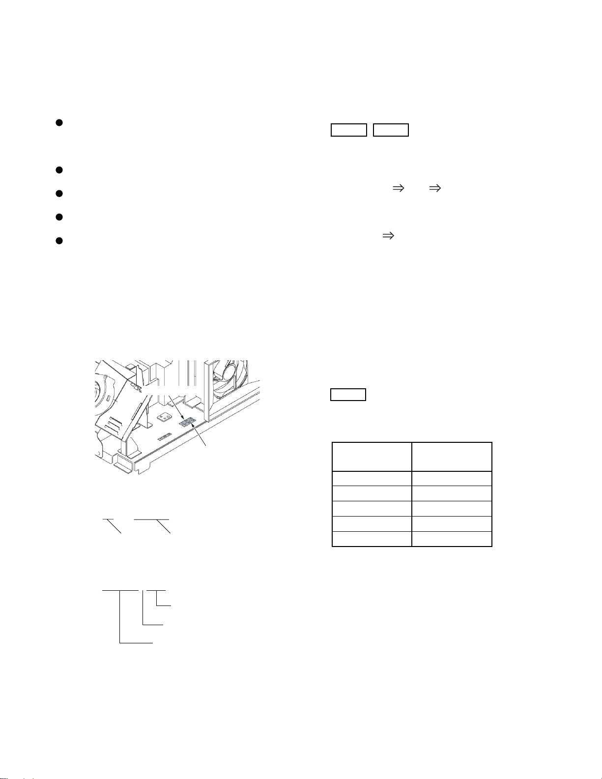
1 FAN Replacement
1-1. For replacing FAN for cooling heatsink, remove 2
screws.
For replacing FAN for cooling lamp, detach FAN hood
located on LIGHT ENGINE by removing 2 screws and
then remove 4 screws.
FAN for cooling lamp
FAN for cooling heatsink
2. Replacement of Ballast Power Unit
2-1. Remove lamp unit by loosening 2 screws.
(Refer to pages 13 to 15)
2-2. Remove 2 screws holding chassis of ballast power unit
to detach the chassis.
Note:
Treat with enough care so as not to damage the
cable for lamp power.
2-3. Detach the ballast power unit by removing 4 substrate
stoppers that hold the ballast power unit.
CAUTION
Precautions When Exchanging Ballast Power Units
When you install a new ballast power unit, install it
while pushing the four corners of the board directly.
Installation while pressing the heatsink may cause
the pattern crack.
3. Replacement of Temperature Breaker
3-1. Remove 2 screws for replacing the temperature breaker
for lamp.
Ballast power unit
4 Replacement of Sensor Unit (Photo Detector
Substrate) & Motor Unit (Motor Substrate)
4-1. Remove 2 screws fixing a color wheel cover and UV
filter box.
-
13
-
Page 14

4-2. Remove one screw for motor unit.
Motor substrate
4-3. Remove 2 screws holding Photo Detector substrate.
Color wheel
Photo Detector substrate
Caution
When removing screws, do not damage the
color wheel with drivers, etc. Even a small impact may damage the color wheel.
Make sure not to touch the color wheel.
Don’t remove other screws by any means.
-
14
-
Page 15

EXPLODED VIEW
4 screws
K601
12 screws
W661
12 screws
12 screws
A101
W662
4 screws
4 screws
A201
A215
2 screws
A101
3 screws
A278
A271
2 screws
A222
A204
A227
2 screws
UV03
1 screw
A333
-
15
13 screws
-
Page 16

MECHANICAL DISASSEMBLY
1 Bezel Ass'y Removal 2 Mirror Removal
12 screws
K601 (MIRROR)
4 screws
A201
A101
12 screws
3 Back Cover Removal 4 Speaker & Touchpad Removal
A101
4 screws
A204
4 screws
A227
13 screws
A222
5 Bracket Removal 6 Optical Engine Removal
A278
2 screws
1 screw
A333
A271
2 screws
A215
3 screws
-
16
A333
2 screws
-
Page 17

CHASSIS AND CABINET REPLACEMENT PARTS LIST
WARNING: BEFORE SERVICING THIS CHASSIS, READ THE “X-RAY RADIATION PRECAUTION”, “SAFETY PRECAUTION”
AND “PRODUCT SAFETY NOTICE” ON PAGE 3 OF THIS MANUAL.
CAUTION: The international hazard symbols " " in the schematic diagram and the parts list designate com-ponents which
have special characteristics important for safety and should be replaced only with types identical to those in the original
circuit or specified in the parts list. The mounting position of replacements is to be identical with originals. Before replacing
any of these components, read carefully the PRODUCT SAFETY NOTICE. Do not degrade the safety of the receiver through
improper servicing.
NOTICE:
•
The part number must be used when ordering parts, in order to assist in processing, be sure to include the Model
number and Description.
•
The PC board assembly with ∗ mark is no longer available after the end of the production.
Model : 46HM94/52HM94/62HM94
Capacitors ............. CD : Ceramic Disk PF : Plastic Film EL : Electrolytic
Resistors ............... CF : Carbon Film CC : Carbon Composition MF : Metal Film
OMF : Oxide Metal Film VR : Variable Resistor FR : Fusible Resistor
(All CD and PF capacitors are ±5%, 50V and all resistors, ±5%, 1/6W unless otherwise noted.)
Location
No.
Parts No. Description
[#1:46HM94]
[#2:52HM94]
[#3:62HM94]
CAPACITORS
C101 24797339 ELECTROLYTIO CE04G, 50V 3.3UF M
C102 24665221 ELECTROLYTIC CE04Q, 10V 220UF M 3A
C105 24100102 CERAMIC CHIP, 50V F 1000PF Z
C106 24669479 ELECTROLYTIC, 50V 4.7UF M 3A
C107 24666221 ELECTROLYTIC 04Q, 16V 220UF M 3A
C108 24665221 ELECTROLYTIC CE04Q, 10V 220UF M 3A
C109 24100104 CERAMIC CHIP, 25V F 0.1UF Z
C110 24794101 ELECTROLYTIC, 16V 100UF M
C502 24092730 CERAMIC CHIP, 16V B 0.1UF K
C508 24092730 CERAMIC CHIP, 16V B 0.1UF K
C515 24092730 CERAMIC CHIP, 16V B 0.1UF K
C516 24109103 CERAMIC CHIP, 50V B 0.01UF K
C517 24092731 CERAMIC CHIP, 16V B 1UF K
C524 24092730 CERAMIC CHIP, 16V B 0.1UF K
C538 24630727 ELECTROLYTIC, 6.3V 330UF M 7L 3A
C582 24105101 CERAMIC CHIP, 50V CH 100PF J
C601 24109122 CERAMIC CHIP, 50V B 1200PF K
C602 24109122 CERAMIC CHIP, 50V B 1200PF K
C603 24073084 ELECTROLYTIC, 50V 4.7UF M 3A
C604 24073084 ELECTROLYTIC, 50V 4.7UF M 3A
C605 24073086 ELECTROLYTIC, 50V 10UF M 3A
C606 24073086 ELECTROLYTIC, 50V 10UF M 3A
C607 24073053 ELECTROLYTIC, 25V 100UF M 3A
C608 24073086 ELECTROLYTIC, 50V 10UF M 3A
C612 24073054 ELECTROLYTIC CE04P 25V 220UF M 3A
C621 24109822 CERAMIC CHIP, 50V B 8200PF K
C622 24109822 CERAMIC CHIP, 50V B 8200PF K
C661 24073084 ELECTROLYTIC, 50V 4.7UF M 3A
C662 24073086 ELECTROLYTIC, 50V 10UF M 3A
C663 24073086 ELECTROLYTIC, 50V 10UF M 3A
C665 24109103 CERAMIC CHIP, 50V B 0.01UF K
C666 24073084 ELECTROLYTIC, 50V 4.7UF M 3A
C667 24794100 ELECTROLYTIC, 16V 10UF M
C668 24105560 CERAMIC CHIP, 50V CH 56PF J
C669 24105560 CERAMIC CHIP, 50V CH 56PF J
C680 24073073 ELECTROLYTIC, 35V 2200UF M 3A
Location
No.
C681 24109103 CERAMIC CHIP, 50V B 0.01UF K
C682 24073082 ELECTROLYTIC, 50V 2.2UF M 3A
C683 24073053 ELECTROLYTIC, 25V 100UF M 3A
C684 24795470 ELECTROLYTIC 04G, 25V 47UF M
C801 24503004 PLASTIC FILM, AC275V 0.47UF M
C802 24503002 PLASTIC FILM, AC275V 0.22UF M
C803 24503002 PLASTIC FILM, AC275V 0.22UF M
C805 24092281 CERAMIC DISC, AC250V E 4700PF
C809 24073103 200V 680UF RUBIKON CE692Q2D681M
C810 24073103 200V 680UF RUBIKON CE692Q2D681M
C811 24092557 CERAMIC DISC, AC250V E 2200PF M
C812 24092557 CERAMIC DISC, AC250V E 2200PF M
C816 24092555 CERAMIC DISC, AC250V E 1000PF M
C861 24092342 CERAMIC DISC, 2KV R 560PF K
C862 24503045 PLASTIC FILM, 63V 0.22UF J
C863 24212221 CERAMIC DISC, 50V B 220PF K
C864 24590681 PLASTIC FILM CQ922M 50V 680PF J
C865 24073063 ELECTROLYTIC CE04P 35V 4.7UF M 3A
C866 24820223 PLASTIC FILM, 630V 0.022UF J
C868 24073068 ELECTROLYTIC, 35V 100UF M 3A
C883 24567104 PLASTIC FILM, 50V 0.1UF J
C884 24214331 CERAMIC DISC, 500V B 330PF K
C885 24073191 ELECTROLYTIC CE04P 35V 1500UF M 3A
C890 24214331 CERAMIC DISC, 500V B 330PF K
C891 24073161 ELECTROLYTIC CE04P 16V 3900UF M 3A
C892 24214331 CERAMIC DISC, 500V B 330PF K
C893 24073173 ELECTROLYTIC CE04P 10V 3900UF M 3A
C894 24214331 CERAMIC DISC, 500V B 330PF K
C895 24073095 ELECTROLYTIC, 50V 2200UF M 3A
C898 24503041 PLASTIC FILM , 63V 0.1UF J
C8200 24073067 ELECTROLYTIC CE04P 35V 47UF M 3A
C8201 24503047 PLASTIC FILM, 63V 0.33UF J
C8202 24073169 ELECTROLYTIC CE04P 25V 470UF M 3A
C8210 24073037 ELECTROLYTIC, 16V 47UF M 3A
C8211 24503047 PLASTIC FILM, 63V 0.33UF J
C8212 24503047 PLASTIC FILM, 63V 0.33UF J
C8214 24073169 ELECTROLYTIC CE04P 25V 470UF M 3A
C8220 24073068 ELECTROLYTIC, 35V 100UF M 3A
C8221 24073169 ELECTROLYTIC CE04P 25V 470UF M 3A
C8223 24073086 ELECTROLYTIC, 50V 10UF M 3A
C8224 24073087 ELECTROLYTIC, 50V 22UF M 3A
Parts No. Description
-
17
-
Page 18

Location
No.
C8225 24073141 ELECTROLYTIC CE04P 10V 1000UF M 3A
C8240 24073038 ELECTROLYTIC, 16V 100UF M 3A
C8241 24503047 PLASTIC FILM, 63V 0.33UF J
C8242 24073141 ELECTROLYTIC CE04P 10V 1000UF M 3A
C8250 24073141 ELECTROLYTIC CE04P 10V 1000UF M 3A
C8251 24567334 PLASTIC FILM, 50V 0.33UF J
C8252 24073141 ELECTROLYTIC CE04P 10V 1000UF M 3A
C8253 24669339 ELECTROLYTIC, 50V 3.3UF M
C8905 24073002 ELECTROLYTIC CE04P 6.3V 220UF M 3A
C8911 24503047 PLASTIC FILM, 63V 0.33UF J
C8912 24503047 PLASTIC FILM, 63V 0.33UF J
C8930 24073067 ELECTROLYTIC CE04P 35V 47UF M 3A
C8931 24503047 PLASTIC FILM, 63V 0.33UF J
C8932 24073152 ELECTROLYTIC CE04P 16V 330UF M 3A
C8933 24073069 ELECTROLYTIC CE04P 35V 220UF M 3A
C8940 24073067 ELECTROLYTIC CE04P 35V 47UF M 3A
C8941 24503047 PLASTIC FILM, 63V 0.33UF J
C8942 24073152 ELECTROLYTIC CE04P 16V 330UF M 3A
C8943 24073069 ELECTROLYTIC CE04P 35V 220UF M 3A
CA81 24109183 CERAMIC CHIP, 50V B 18000PF K
CA82 24109183 CERAMIC CHIP, 50V B 18000PF K
CA83 24109102 CERAMIC CHIP, 50V B 1000PF K
CA84 24109183 CERAMIC CHIP, 50V B 18000PF K
CA85 24109183 CERAMIC CHIP, 50V B 18000PF K
CA86 24109183 CERAMIC CHIP, 50V B 18000PF K
CA87 24109183 CERAMIC CHIP, 50V B 18000PF K
CA88 24109102 CERAMIC CHIP, 50V B 1000PF K
CA89 24109183 CERAMIC CHIP, 50V B 18000PF K
CA90 24109183 CERAMIC CHIP, 50V B 18000PF K
CA91 24092730 CERAMIC CHIP, 16V B 0.1UF K
CA92 24092730 CERAMIC CHIP, 16V B 0.1UF K
CA93 24619040 ELEC. CHIP, 16V 10UF M 3A
CA94 24619040 ELEC. CHIP, 16V 10UF M 3A
CA95 24092730 CERAMIC CHIP, 16V B 0.1UF K
CA96 24092730 CERAMIC CHIP, 16V B 0.1UF K
CA97 24105330 CERAMIC CHIP, 50V CH 33PF J
CA98 24105330 CERAMIC CHIP, 50V CH 33PF J
CB01 24794470 ELECTROLYTIC, 16V 47UF M
CB51 24590103 PLASTIC FILM, 50V 0.01UF J
CB52 24794470 ELECTROLYTIC, 16V 47UF M
CB53 24503041 PLASTIC FILM , 63V 0.1UF J
CB54 24436221 CERAMIC DISC, 50V SL 220PF J
CB55 24797010 ELECTROLYTIC, 50V 1UF M
CB56 24794470 ELECTROLYTIC, 16V 47UF M
CB58 24794470 ELECTROLYTIC, 16V 47UF M
CB59 24590103 PLASTIC FILM, 50V 0.01UF J
CB60 24794100 ELECTROLYTIC, 16V 10UF M
CB61 24503041 PLASTIC FILM , 63V 0.1UF J
CB81 24092730 CERAMIC CHIP, 16V B 0.1UF K
CB504 24794100 ELECTROLYTIC, 16V 10UF M
CB505 24092398 CERAMIC DISC, 25V 0.1UF Z
CC01 24092730 CERAMIC CHIP, 16V B 0.1UF K
CC02 24092730 CERAMIC CHIP, 16V B 0.1UF K
CC03 24092730 CERAMIC CHIP, 16V B 0.1UF K
CC04 24619100 ELECTROLYTIC, 16V 10UF M
CC05 24092730 CERAMIC CHIP, 16V B 0.1UF K
CC06 24092730 CERAMIC CHIP, 16V B 0.1UF K
CC07 24619100 ELECTROLYTIC, 16V 10UF M
CC08 24092730 CERAMIC CHIP, 16V B 0.1UF K
CC09 24092730 CERAMIC CHIP, 16V B 0.1UF K
CC10 24092730 CERAMIC CHIP, 16V B 0.1UF K
CC11 24619100 ELECTROLYTIC, 16V 10UF M
CC12 24092538 CERAMIC CHIP, 10V F 1UF Z
CC13 24092730 CERAMIC CHIP, 16V B 0.1UF K
CC14 24092730 CERAMIC CHIP, 16V B 0.1UF K
CC15 24619100 ELECTROLYTIC, 16V 10UF M
Parts No. Description
Location
No.
CC16 24092730 CERAMIC CHIP, 16V B 0.1UF K
CC17 24619100 ELECTROLYTIC, 16V 10UF M
CC18 24092730 CERAMIC CHIP, 16V B 0.1UF K
CC19 24092730 CERAMIC CHIP, 16V B 0.1UF K
CC20 24619100 ELECTROLYTIC, 16V 10UF M
CC22 24092538 CERAMIC CHIP, 10V F 1UF Z
CC24 24092538 CERAMIC CHIP, 10V F 1UF Z
CC25 24092538 CERAMIC CHIP, 10V F 1UF Z
CC26 24092730 CERAMIC CHIP, 16V B 0.1UF K
CC27 24092730 CERAMIC CHIP, 16V B 0.1UF K
CC28 24619102 ELECTROLYTIC, 16V 47UF M
CC30 24619100 ELECTROLYTIC, 16V 10UF M
CC31 24092730 CERAMIC CHIP, 16V B 0.1UF K
CC32 24619100 ELECTROLYTIC, 16V 10UF M
CC33 24092730 CERAMIC CHIP, 16V B 0.1UF K
CC34 24092730 CERAMIC CHIP, 16V B 0.1UF K
CC35 24092730 CERAMIC CHIP, 16V B 0.1UF K
CC36 24619100 ELECTROLYTIC, 16V 10UF M
CC40 24092538 CERAMIC CHIP, 10V F 1UF Z
CC41 24092730 CERAMIC CHIP, 16V B 0.1UF K
CC42 24109103 CERAMIC CHIP, 50V B 0.01UF K
CE01 24503002 PLASTIC FILM, AC275V 0.22UF M
CE04 24092281 CERAMIC DISC, AC250V E 4700PF
CE05 24092281 CERAMIC DISC, AC250V E 4700PF
CE07 24092565 CERAMIC DISC, AC250V B 470PF K
CE08 24092565 CERAMIC DISC, AC250V B 470PF K
CE09 24092565 CERAMIC DISC, AC250V B 470PF K
CE10 24073217 ELECTROLYTIC 692Q 200V 560UF M
CE11 24591332 PLASTIC FILM, 50V 3300PF J
CE12 24073053 ELECTROLYTIC, 25V 100UF M 3A
CE13 24503213 PLASTIC FILM CF92 T 1500VH 1500PF H
CE14 24591471 PLASTIC FILM, 50V 470PF J
CE15 24092339 CERAMIC DISC, 2KV 330PF K
CE16 24212102 CERAMIC DISC, 50V B 1000PF K
CE17 24503041 PLASTIC FILM , 63V 0.1UF J
CE43 24503041 PLASTIC FILM , 63V 0.1UF J
CE50 24676100 ELECTROLYTIC CE04Q, 100V 10UF M 3A
CE51 24073155 ELECTROLYTIC, 16V 1000UF M 3A
CE52 24503041 PLASTIC FILM , 63V 0.1UF J
CE53 24214221 CERAMIC DISC, 500V B 220PF K
CE54 24503041 PLASTIC FILM , 63V 0.1UF J
CE55 24617006 ELECTROLYTIC 04CH, 25V 820UF M
CE56 24665221 ELECTROLYTIC CE04Q, 10V 220UF M 3A
CE57 24073038 ELECTROLYTIC, 16V 100UF M 3A
CE58 24073038 ELECTROLYTIC, 16V 100UF M 3A
CE59 24666331 ELECTROLYTIC 04Q, 16V 330UF M 3A
CE61 24073020 ELECTROLYTIC, 10V 1000UF M 3A
CE63 24666470 ELECTORLYTIC, 16V 47UF M 3A
CE64 24503047 PLASTIC FILM, 63V 0.33UF J
CE65 24666470 ELECTORLYTIC, 16V 47UF M 3A
CE66 24073138 ELECTROLYTIC CE04P 10V 220UF M 3A
CE67 24503047 PLASTIC FILM, 63V 0.33UF J
CE68 24073138 ELECTROLYTIC CE04P 10V 220UF M 3A
CE69 24669339 ELECTROLYTIC, 50V 3.3UF M
CE71 24214331 CERAMIC DISC, 500V B 330PF K
CE72 24214331 CERAMIC DISC, 500V B 330PF K
CE73 24214331 CERAMIC DISC, 500V B 330PF K
CE74 24214331 CERAMIC DISC, 500V B 330PF K
CE75 24214331 CERAMIC DISC, 500V B 330PF K
CE76 24214331 CERAMIC DISC, 500V B 330PF K
CE79 24669220 ELECTROLYTIC, 50V 22UF M 3A
CE80 24073157 ELECTROLYTIC CE04P 16V 1500UF M 3A
CE81 24073157 ELECTROLYTIC CE04P 16V 1500UF M 3A
CE82 24676470 ELECTROLYTIC, 100V 47UF M 3A
CE83 24073155 ELECTROLYTIC, 16V 1000UF M 3A
CE84 24073141 ELECTROLYTIC CE04P 10V 1000UF M 3A
Parts No. Description
-
18
-
Page 19

Location
No.
CE85 24073158 ELECTROLYTIC CE04P 16V 2200UF M 3A
CE86 24073133 ELECTROLYTIC CE04P 6.3V 3300UF M 3A
CE87 24073141 ELECTROLYTIC CE04P 10V 1000UF M 3A
CE88 24073155 ELECTROLYTIC, 16V 1000UF M 3A
CF01 24073152 ELECTROLYTIC CE04P 16V 330UF M 3A
CR509 24203101 ELECTROLYTIC, 16V 100UF M 7L 3A
CS01 24092795 CERAMIC CHIP, 6.3V B 2.2UF K
CS02 24092795 CERAMIC CHIP, 6.3V B 2.2UF K
CS05 24092795 CERAMIC CHIP, 6.3V B 2.2UF K
CS06 24092795 CERAMIC CHIP, 6.3V B 2.2UF K
CS07 24092795 CERAMIC CHIP, 6.3V B 2.2UF K
CS08 24092795 CERAMIC CHIP, 6.3V B 2.2UF K
CS09 24092795 CERAMIC CHIP, 6.3V B 2.2UF K
CS10 24092795 CERAMIC CHIP, 6.3V B 2.2UF K
CS11 24092795 CERAMIC CHIP, 6.3V B 2.2UF K
CS12 24092795 CERAMIC CHIP, 6.3V B 2.2UF K
CS13 24092795 CERAMIC CHIP, 6.3V B 2.2UF K
CS14 24092795 CERAMIC CHIP, 6.3V B 2.2UF K
CS15 24092795 CERAMIC CHIP, 6.3V B 2.2UF K
CS16 24092795 CERAMIC CHIP, 6.3V B 2.2UF K
CS19 24092795 CERAMIC CHIP, 6.3V B 2.2UF K
CS20 24092795 CERAMIC CHIP, 6.3V B 2.2UF K
CS21 24085987 ELEC. NONPOLAR, 16V 4.7UF M 7L NP
CS22 24085987 ELEC. NONPOLAR, 16V 4.7UF M 7L NP
CS25 24109103 CERAMIC CHIP, 50V B 0.01UF K
CS26 24794470 ELECTROLYTIC, 16V 47UF M
CS27 24794220 ELECTROLYTIC, 16V 22UF M
CS28 24794100 ELECTROLYTIC, 16V 10UF M
CS29 24794100 ELECTROLYTIC, 16V 10UF M
CS30 24794100 ELECTROLYTIC, 16V 10UF M
CS33 24092795 CERAMIC CHIP, 6.3V B 2.2UF K
CS34 24092795 CERAMIC CHIP, 6.3V B 2.2UF K
CV01 24092621 CERAMIC CHIP, 10V B 1UF K
CV02 24092621 CERAMIC CHIP, 10V B 1UF K
CV03 24092621 CERAMIC CHIP, 10V B 1UF K
CV04 24100104 CERAMIC CHIP, 25V F 0.1UF Z
CV05 24092621 CERAMIC CHIP, 10V B 1UF K
CV06 24092621 CERAMIC CHIP, 10V B 1UF K
CV11 24092621 CERAMIC CHIP, 10V B 1UF K
CV13 24100104 CERAMIC CHIP, 25V F 0.1UF Z @U103
CV14 24092621 CERAMIC CHIP, 10V B 1UF K @U103
CV15 24100104 CERAMIC CHIP, 25V F 0.1UF Z @U103
CV27 24762471 ELECTROLYTIC, 04G 10V 470UF M
CV29 24763101 ELECTROLYTIC, 16V 100UF M
CV30 24092730 CERAMIC CHIP, 16V B 0.1UF K
CV38 24109102 CERAMIC CHIP, 50V B 1000PF K
CV39 24109102 CERAMIC CHIP, 50V B 1000PF K
CV46 24092621 CERAMIC CHIP, 10V B 1UF K
CV70 24794101 ELECTROLYTIC, 16V 100UF M
CV71 24092730 CERAMIC CHIP, 16V B 0.1UF K
CV72 24794220 ELECTROLYTIC, 16V 22UF M
CV73 24092730 CERAMIC CHIP, 16V B 0.1UF K
CV74 24092730 CERAMIC CHIP, 16V B 0.1UF K
CV75 24092730 CERAMIC CHIP, 16V B 0.1UF K
CV245 24092621 CERAMIC CHIP, 10V B 1UF K
CV246 24092621 CERAMIC CHIP, 10V B 1UF K
CV247 24092621 CERAMIC CHIP, 10V B 1UF K
CV249 24092621 CERAMIC CHIP, 10V B 1UF K
CV250 24092621 CERAMIC CHIP, 10V B 1UF K
CV251 24092621 CERAMIC CHIP, 10V B 1UF K
CY504 24109222 CERAMIC CHIP, 50V B 2200PF K
CY505 24105120 CERAMIC CHIP, 50V CH 12PF J
CY512 24092463 CERAMIC CHIP, 16V B 0.22UF K
Parts No. Description
24794100 ELECTROLYTIC, 16V 10UF M @UV03
24232103 CERAMIC DISC, 50V F 0.01UF Z @UV03
24232103 CERAMIC DISC, 50V F 0.01UF Z @UV03
Location
No.
Parts No. Description
RESISTORS
R010 24011102 CHIP, METAL FILM, 1/20W 1K OHM J
R150 24011101 CHIP, METAL FILM, 1/20W 100 OHM J
R153 24011101 CHIP, METAL FILM, 1/20W 100 OHM J
R264 24011750 CHIP, METAL FILM, 1/20W 75 OHM J
R265 24011750 CHIP, METAL FILM, 1/20W 75 OHM J
R266 24011750 CHIP, METAL FILM, 1/20W 75 OHM J
R286 24011750 CHIP, METAL FILM, 1/20W 75 OHM J
R287 24011750 CHIP, METAL FILM, 1/20W 75 OHM J
R288 24011750 CHIP, METAL FILM, 1/20W 75 OHM J
R347 24011101 CHIP, METAL FILM, 1/20W 100 OHM J
R502 24011101 CHIP, METAL FILM, 1/20W 100 OHM J
R504 24011103 CHIP, METAL FILM, 1/20W 10K OHM J
R505 24011123 CHIP, METAL FILM, 1/20W 12K OHM J
R506 24011222 CHIP, METAL FILM, 1/20W 2.2K OHM J
R510 24011123 CHIP, METAL FILM, 1/20W 12K OHM J
R511 24011103 CHIP, METAL FILM, 1/20W 10K OHM J
R512 24011123 CHIP, METAL FILM, 1/20W 12K OHM J
R513 24011222 CHIP, METAL FILM, 1/20W 2.2K OHM J
R514 24011332 CHIP, 1/20W 3.3K OHM J
R516 24011472 CHIP, 1/20W 4.7K OHM J
R520 24011101 CHIP, METAL FILM, 1/20W 100 OHM J
R521 24011101 CHIP, METAL FILM, 1/20W 100 OHM J
R523 24011332 CHIP, 1/20W 3.3K OHM J
R524 24011182 CHIP, METAL FILM, 1/20W 1.8K OHM J
R545 24011101 CHIP, METAL FILM, 1/20W 100 OHM J
R548 24011102 CHIP, METAL FILM, 1/20W 1K OHM J
R550 24011332 CHIP, 1/20W 3.3K OHM J
R552 24011152 CHIP, METAL FILM, 1/20W 1.5K OHM J
R560 24011332 CHIP, 1/20W 3.3K OHM J
R561 24011471 CHIP, 1/20W 470 OHM J
R574 24011222 CHIP, METAL FILM, 1/20W 2.2K OHM J
R575 24011103 CHIP, METAL FILM, 1/20W 10K OHM J
R576 24011123 CHIP, METAL FILM, 1/20W 12K OHM J
R601 24011822 CHIP, 1/20W 8.2K OHM J
R602 24011822 CHIP, 1/20W 8.2K OHM J
R603 24011122 CHIP, METAL FILM, 1/20W 1.2K OHM J
R604 24011122 CHIP, METAL FILM, 1/20W 1.2K OHM J
R605 24011101 CHIP, METAL FILM, 1/20W 100 OHM J
R606 24011101 CHIP, METAL FILM, 1/20W 100 OHM J
R609 24011563 CHIP, 1/20W 56K OHM J
R610 24011223 CHIP, 1/20W 22K OHM J
R611 24011103 CHIP, METAL FILM, 1/20W 10K OHM J
R612 24011222 CHIP, METAL FILM, 1/20W 2.2K OHM J
R613 24011223 CHIP, 1/20W 22K OHM J
R614 24011103 CHIP, METAL FILM, 1/20W 10K OHM J
R615 24011104 CHIP, METAL FILM, 1/20W 100K OHM J
R616 24011822 CHIP, 1/20W 8.2K OHM J
R621 24011391 CHIP, 1/20W 390 OHM J
R622 24011391 CHIP, 1/20W 390 OHM J
R626 24011223 CHIP, 1/20W 22K OHM J
R627 24011223 CHIP, 1/20W 22K OHM J
R661 24011102 CHIP, METAL FILM, 1/20W 1K OHM J
R662 24011333 CHIP, METAL FILM, 1/20W 33K OHM J
R663 24011822 CHIP, 1/20W 8.2K OHM J
R665 24011223 CHIP, 1/20W 22K OHM J
R666 24011473 CHIP, 1/20W 47K OHM J
R667 24011223 CHIP, 1/20W 22K OHM J
R668 24011473 CHIP, 1/20W 47K OHM J
R671 24011102 CHIP, METAL FILM, 1/20W 1K OHM J
R672 24011333 CHIP, METAL FILM, 1/20W 33K OHM J
R673 24011822 CHIP, 1/20W 8.2K OHM J
R674 24011472 CHIP, 1/20W 4.7K OHM J
R676 24011104 CHIP, METAL FILM, 1/20W 100K OHM J
R677 24011104 CHIP, METAL FILM, 1/20W 100K OHM J
R681 24011222 CHIP, METAL FILM, 1/20W 2.2K OHM J
-
19
-
Page 20

Location
No.
R682 24011473 CHIP, 1/20W 47K OHM J
R683 24011223 CHIP, 1/20W 22K OHM J
R684 24011223 CHIP, 1/20W 22K OHM J
R687 24011103 CHIP, METAL FILM, 1/20W 10K OHM J
R688 24011224 CHIP, METAL FILM, 1/20W 220K OHM J
R693 24000445 CHIP JUMPER, 1608TYPE
R697 24553561 OXIDE METAL FILM, 1W 560 OHM J
R698 24011103 CHIP, METAL FILM, 1/20W 10K OHM J
R699 24011103 CHIP, METAL FILM, 1/20W 10K OHM J
R810 24568479 CERAMIC COVERED, 7W 4.7 OHM J
R811 24007061 CERAMIC COVERED, 2W 1.8 OHM K
R842 24376563 CARB0N FILM, 1/2W 56K OHM J
R843 24376563 CARB0N FILM, 1/2W 56K OHM J
R844 24366103 CARBON FILM, 1/6W 10K OHM J
R845 24366102 CARBON FILM, 1/6W 1K OHM J
R846 24366471 CARBON FILM, 1/6W 470 OHM J
R847 24366473 CARBON FILM, 1/6W 47K OHM J
R848 24366102 CARBON FILM, 1/6W 1K OHM J
R849 24552470 OXIDE METAL FILM, 1/2W 47 OHM J
R850 24366103 CARBON FILM, 1/6W 10K OHM J
R860 24382101 OXIDE METAL FILM, 1W 100 OHM J
R861 24383333 OXIDE METAL FILM, 2W 33K OHM J
R862 24019463 METAL PLATE RK99 2W R22 J
R863 24019461 METAL PLATE, 2W 0.15 OHM J
R864 24321828 METAL FILM, 1/2W 0.82 OHM J
R865 24381221 OXIDE METAL FILM, 1/2W 220 OHM J
R866 24366681 CARBON FILM, 1/6W 680 OHM J
R867 24366152 CARBON FILM, 1/6W 1.5K OHM J
R868 24555473 METAL OXIDE FILM B 3W 47K J
R869 24366152 CARBON FILM, 1/6W 1.5K OHM J
R870 24366154 CARBON FILM, 1/6W 150K OHM J
R881 24366222 CARBON FILM, 1/6W 2.2K OHM J
R882 24366471 CARBON FILM, 1/6W 470 OHM J
R885 24366102 CARBON FILM, 1/6W 1K OHM J
R886 24000525 METAL FILM, 1/4W 4.7K OHM F
R887 24367683 CARBON FILM, 1/6W 68K OHM G
R888 24000525 METAL FILM, 1/4W 4.7K OHM F
R891 24555331 OXIDE METAL FILM, 3W 330 OHM J
R892 24555331 OXIDE METAL FILM, 3W 330 OHM J
R899 24005014 METAL FILM, 1W 8.2M OHM J
R8200 24367390 CARBON FILM 1/6W 390 G
R8210 24000370 METAL FILM, 1/4W 3.3K OHM F
R8211 24000527 METAL FILM, 1/4W 5.6K OHM F
R8215 24366224 CARBON FILM, 1/6W 220K OHM J
R8220 24367390 CARBON FILM 1/6W 390 G
R8222 24367820 CARBON FILM, 1/6W 82 OHM G
R8240 24000366 METAL FILM, 1/4W 2.2K OHM F
R8241 24000360 METAL FILM, 1/4W 1.2K OHM F
R8242 24367101 CARBON FILM, 1/6W 100 OHM G
R8250 24000145 METAL FILM, 1/4W 330 OHM F
R8251 24000145 METAL FILM, 1/4W 330 OHM F
R8252 24367392 CARBON FILM, 1/6W 3.9K OHM G
R8902 24366332 CARBON FILM, 1/6W 3.3K OHM J
R8903 24366332 CARBON FILM, 1/6W 3.3K OHM J
R8904 24366472 CARBON FILM, 1/6W 4.7K OHM J
R8905 24366681 CARBON FILM, 1/6W 680 OHM J
R8908 24366104 CARBON FILM, 1/6W 100K OHM J
R8910 24366472 CARBON FILM, 1/6W 4.7K OHM J
R8911 24366103 CARBON FILM, 1/6W 10K OHM J
R8912 24366223 CARBON FILM, 1/6W 22K OHM J
R8913 24366334 CARBON FILM, 1/6W 330K OHM J
R8914 24366223 CARBON FILM, 1/6W 22K OHM J
R8915 24366102 CARBON FILM, 1/6W 1K OHM J
R8931 24367123 CARBON FILM, 1/6W 12K OHM G
R8932 24367152 CARBON FILM, 1/6W 1.5K OHM G
R8934 24367472 CARBON FILM, 1/6W 4.7K OHM G
Parts No. Description
Location
No.
R8941 24367123 CARBON FILM, 1/6W 12K OHM G
R8942 24367152 CARBON FILM, 1/6W 1.5K OHM G
R8944 24367472 CARBON FILM, 1/6W 4.7K OHM G
R8950 24366103 CARBON FILM, 1/6W 10K OHM J
R8951 24366103 CARBON FILM, 1/6W 10K OHM J
RA71 24011822 CHIP, 1/20W 8.2K OHM J
RA72 24011153 CHIP, METAL FILM, 1/2OW 15K OHM J
RA73 24011273 CHIP, 1/20W 27K OHM J
RA75 24011822 CHIP, 1/20W 8.2K OHM J
RA76 24011153 CHIP, METAL FILM, 1/2OW 15K OHM J
RA77 24011114 CHIP, METAL FILM, 1/20W 110K OHM J
RA78 24000445 CHIP JUMPER, 1608TYPE
RA79 24000445 CHIP JUMPER, 1608TYPE
RA81 24011102 CHIP, METAL FILM, 1/20W 1K OHM J
RA82 24011102 CHIP, METAL FILM, 1/20W 1K OHM J
RA84 24011102 CHIP, METAL FILM, 1/20W 1K OHM J
RA85 24011102 CHIP, METAL FILM, 1/20W 1K OHM J
RA86 24011102 CHIP, METAL FILM, 1/20W 1K OHM J
RA87 24011102 CHIP, METAL FILM, 1/20W 1K OHM J
RA89 24011102 CHIP, METAL FILM, 1/20W 1K OHM J
RA90 24011102 CHIP, METAL FILM, 1/20W 1K OHM J
RA91 24011470 CHIP, 1/20W 47 OHM J
RA92 24011470 CHIP, 1/20W 47 OHM J
RA93 24011103 CHIP, METAL FILM, 1/20W 10K OHM J
RA94 24011332 CHIP, 1/20W 3.3K OHM J
RA95 24011332 CHIP, 1/20W 3.3K OHM J
RB15 24366471 CARBON FILM, 1/6W 470 OHM J
RB19 24366470 CARBON FILM, 1/6W 47 OHM J
RB51 24366224 CARBON FILM, 1/6W 220K OHM J
RB52 24366123 CARBON FILM, 1/6W 12K OHM J
RB53 24366123 CARBON FILM, 1/6W 12K OHM J
RB54 24366123 CARBON FILM, 1/6W 12K OHM J
RB55 24366224 CARBON FILM, 1/6W 220K OHM J
RB56 24366151 CARBON FILM, 1/6W 150 OHM J
RB57 24366103 CARBON FILM, 1/6W 10K OHM J
RB58 24366103 CARBON FILM, 1/6W 10K OHM J
RB59 24366122 CARBON FILM, 1/6W 1.2K OHM J
RB60 24366224 CARBON FILM, 1/6W 220K OHM J
RB61 24366100 CARBON FILM, 1/6W 10 OHM J
RB62 24366272 CARBON FILM, 1/6W 2.7K OHM J
RB63 24366271 CARBON FILM, 1/6W 270 OHM J
RB67 24366221 CARBON FILM, 1/6W 220 OHM J
RB69 24366272 CARBON FILM, 1/6W 2.7K OHM J
RB70 24366331 CARBON FILM, 1/6W 330 OHM J
RB81 24011222 CHIP, METAL FILM, 1/20W 2.2K OHM J
RB82 24011471 CHIP, 1/20W 470 OHM J
RB83 24011102 CHIP, METAL FILM, 1/20W 1K OHM J
RB84 24011473 CHIP, 1/20W 47K OHM J
RB87 24011102 CHIP, METAL FILM, 1/20W 1K OHM J
RB88 24011102 CHIP, METAL FILM, 1/20W 1K OHM J
RB89 24011103 CHIP, METAL FILM, 1/20W 10K OHM J
RB90 24011103 CHIP, METAL FILM, 1/20W 10K OHM J
RB92 24011473 CHIP, 1/20W 47K OHM J
RB93 24011102 CHIP, METAL FILM, 1/20W 1K OHM J
RB504 24366104 CARBON FILM, 1/6W 100K OHM J
RB505 24366101 CARBON FILM, 1/6W 100 OHM J
RB506 24366390 CARBON FILM, 1/6W 39 OHM J
RB558 24366223 CARBON FILM, 1/6W 22K OHM J
RB559 24366223 CARBON FILM, 1/6W 22K OHM J
RB561 24366101 CARBON FILM, 1/6W 100 OHM J
RB562 24366104 CARBON FILM, 1/6W 100K OHM J
RB563 24366390 CARBON FILM, 1/6W 39 OHM J
RB567 24366223 CARBON FILM, 1/6W 22K OHM J
RC01 24011223 CHIP, 1/20W 22K OHM J
RC02 24011220 CHIP, METAL FILM, 1/20W 22 OHM J
RC03 24011220 CHIP, METAL FILM, 1/20W 22 OHM J
Parts No. Description
-
20
-
Page 21

Location
No.
RC04 24011220 CHIP, METAL FILM, 1/20W 22 OHM J
RC05 24011220 CHIP, METAL FILM, 1/20W 22 OHM J
RC06 24011220 CHIP, METAL FILM, 1/20W 22 OHM J
RC07 24011220 CHIP, METAL FILM, 1/20W 22 OHM J
RC08 24011220 CHIP, METAL FILM, 1/20W 22 OHM J
RC09 24011270 CHIP, 1/20W 27 OHM J
RC10 24011270 CHIP, 1/20W 27 OHM J
RC13 24000824 CHIP JUMPER, 2125TYPE
RC14 24000824 CHIP JUMPER, 2125TYPE
RC15 24000824 CHIP JUMPER, 2125TYPE
RC16 24011103 CHIP, METAL FILM, 1/20W 10K OHM J
RC17 24000824 CHIP JUMPER, 2125TYPE
RC18 24000824 CHIP JUMPER, 2125TYPE
RC19 24000824 CHIP JUMPER, 2125TYPE
RC20 24000824 CHIP JUMPER, 2125TYPE
RC21 24011103 CHIP, METAL FILM, 1/20W 10K OHM J
RC22 24011104 CHIP, METAL FILM, 1/20W 100K OHM J
RC23 24011103 CHIP, METAL FILM, 1/20W 10K OHM J
RC25 24011103 CHIP, METAL FILM, 1/20W 10K OHM J
RC26 24011103 CHIP, METAL FILM, 1/20W 10K OHM J
RC27 24011102 CHIP, METAL FILM, 1/20W 1K OHM J
RC32 24011331 CHIP, 1/20W 330 OHM J
RC33 24011103 CHIP, METAL FILM, 1/20W 10K OHM J
RC34 24011331 CHIP, 1/20W 330 OHM J
RC35 24011103 CHIP, METAL FILM, 1/20W 10K OHM J
RC36 24011331 CHIP, 1/20W 330 OHM J
RC37 24011103 CHIP, METAL FILM, 1/20W 10K OHM J
RC38 24011331 CHIP, 1/20W 330 OHM J
RC39 24011103 CHIP, METAL FILM, 1/20W 10K OHM J
RC40 24011102 CHIP, METAL FILM, 1/20W 1K OHM J
RC41 24011105 CHIP, METAL FILM, 1/20W 1M OHM J
RC49 24011103 CHIP, METAL FILM, 1/20W 10K OHM J
RC50 24011123 CHIP, METAL FILM, 1/20W 12K OHM J
RC51 24011103 CHIP, METAL FILM, 1/20W 10K OHM J
RC52 24011103 CHIP, METAL FILM, 1/20W 10K OHM J
RC53 24011103 CHIP, METAL FILM, 1/20W 10K OHM J
RC54 24011220 CHIP, METAL FILM, 1/20W 22 OHM J
RC58 24011104 CHIP, METAL FILM, 1/20W 100K OHM J
RC60 24011103 CHIP, METAL FILM, 1/20W 10K OHM J
RC61 24011564 CHIP, 1/20W 560K OHM J
RC62 24011103 CHIP, METAL FILM, 1/20W 10K OHM J
RE10 24382223 OXIDE METAL FILM, 1W 22K OHM J
RE11 24322568 OXIDE METAL FILM, 1W 0.56 OHM J
RE12 24322568 OXIDE METAL FILM, 1W 0.56 OHM J
RE13 24381681 OXIDE METAL FILM, 1/2W 680 OHM J
RE14 24383330 OXIDE FILM 2W 33. J
RE15 24383330 OXIDE FILM 2W 33. J
RE16 24366682 CARBON FILM, 1/6W 6.8K OHM J
RE17 24366152 CARBON FILM, 1/6W 1.5K OHM J
RE18 24381101 OXIDE METAL FILM, 1/2W 100 OHM J
RE22 24366102 CARBON FILM, 1/6W 1K OHM J
RE40 24366471 CARBON FILM, 1/6W 470 OHM J
RE43 24366102 CARBON FILM, 1/6W 1K OHM J
RE44 24000529 METAL FILM, 1/4W 6.8K OHM F
RE45 24000356 METAL FILM, 1/4W 820 OHM F
RE46 24000529 METAL FILM, 1/4W 6.8K OHM F
RE48 24366222 CARBON FILM, 1/6W 2.2K OHM J
RE50 24000147 METAL FILM, 1/4W 470 OHM F
RE51 24000155 METAL FILM 1/4W 15 F
RE52 24000167 METAL FILM, 1/4W 56 OHM F 50P
RE53 24000135 METAL FILM 1/4W 120 F
RE54 24000220 METAL FILM, 1/4W 390 OHM F
RE55 24366223 CARBON FILM, 1/6W 22K OHM J
RE60 24382332 OXIDE FILM 1W 3.3K J
RE80 24000245 METAL FILM, 1/4W 33K OHM F
RE81 24000250 METAL FILM, 1/4W 56K OHM F
Parts No. Description
Location
No.
RF01 24366103 CARBON FILM, 1/6W 10K OHM J
RF02 24366122 CARBON FILM, 1/6W 1.2K OHM J
RF03 24366103 CARBON FILM, 1/6W 10K OHM J
RF04 24366472 CARBON FILM, 1/6W 4.7K OHM J
RF05 24382680 OXIDE METAL FILM, 1W 68 OHM J
RS01 24011562 CHIP, 1/20W 5.6K OHM J
RS02 24011562 CHIP, 1/20W 5.6K OHM J
RS05 24011562 CHIP, 1/20W 5.6K OHM J
RS06 24011562 CHIP, 1/20W 5.6K OHM J
RS07 24011562 CHIP, 1/20W 5.6K OHM J
RS08 24011562 CHIP, 1/20W 5.6K OHM J
RS09 24011562 CHIP, 1/20W 5.6K OHM J
RS10 24011562 CHIP, 1/20W 5.6K OHM J
RS11 24011562 CHIP, 1/20W 5.6K OHM J
RS12 24011562 CHIP, 1/20W 5.6K OHM J
RS13 24011562 CHIP, 1/20W 5.6K OHM J
RS14 24011562 CHIP, 1/20W 5.6K OHM J
RS15 24011562 CHIP, 1/20W 5.6K OHM J
RS16 24011562 CHIP, 1/20W 5.6K OHM J
RS19 24011562 CHIP, 1/20W 5.6K OHM J
RS20 24011562 CHIP, 1/20W 5.6K OHM J
RS21 24011101 CHIP, METAL FILM, 1/20W 100 OHM J
RS22 24011101 CHIP, METAL FILM, 1/20W 100 OHM J
RS23 24011101 CHIP, METAL FILM, 1/20W 100 OHM J
RS24 24011101 CHIP, METAL FILM, 1/20W 100 OHM J
RS27 24011101 CHIP, METAL FILM, 1/20W 100 OHM J
RS28 24011101 CHIP, METAL FILM, 1/20W 100 OHM J
RS29 24011682 CHIP, METAL FILM, 1/20W 6.8K OHM J
RS30 24011182 CHIP, METAL FILM, 1/20W 1.8K OHM J
RS31 24011100 CHIP, METAL FILM, 1/20W 10 OHM J
RS32 24011222 CHIP, METAL FILM, 1/20W 2.2K OHM J
RS33 24011222 CHIP, METAL FILM, 1/20W 2.2K OHM J
RS34 24011102 CHIP, METAL FILM, 1/20W 1K OHM J
RS35 24011102 CHIP, METAL FILM, 1/20W 1K OHM J
RS36 24011102 CHIP, METAL FILM, 1/20W 1K OHM J
RS37 24011223 CHIP, 1/20W 22K OHM J
RS38 24011223 CHIP, 1/20W 22K OHM J
RS39 24011101 CHIP, METAL FILM, 1/20W 100 OHM J
RS40 24011101 CHIP, METAL FILM, 1/20W 100 OHM J
RV007 24011222 CHIP, METAL FILM, 1/20W 2.2K OHM J
RV008 24011101 CHIP, METAL FILM, 1/20W 100 OHM J
RV009 24011101 CHIP, METAL FILM, 1/20W 100 OHM J
RV011 24011102 CHIP, METAL FILM, 1/20W 1K OHM J
RV012 24011101 CHIP, METAL FILM, 1/20W 100 OHM J
RV013 24011271 CHIP, 1/20W 270 OHM J
RV023 24011821 CHIP, 1/20W 820 OHM J
RV024 24011222 CHIP, METAL FILM, 1/20W 2.2K OHM J
RV025 24011101 CHIP, METAL FILM, 1/20W 100 OHM J
RV073 24011102 CHIP, METAL FILM, 1/20W 1K OHM J
RV01 24011101 CHIP, METAL FILM, 1/20W 100 OHM J
RV03 24011101 CHIP, METAL FILM, 1/20W 100 OHM J
RV06 24011101 CHIP, METAL FILM, 1/20W 100 OHM J
RV07 24011562 CHIP, 1/20W 5.6K OHM J
RV08 24011101 CHIP, METAL FILM, 1/20W 100 OHM J
RV09 24011101 CHIP, METAL FILM, 1/20W 100 OHM J
RV10 24011101 CHIP, METAL FILM, 1/20W 100 OHM J
RV11 24011101 CHIP, METAL FILM, 1/20W 100 OHM J
RV12 24011101 CHIP, METAL FILM, 1/20W 100 OHM J
RV14 24011562 CHIP, 1/20W 5.6K OHM J
RV15 24011101 CHIP, METAL FILM, 1/20W 100 OHM J
RV17 24011101 CHIP, METAL FILM, 1/20W 100 OHM J
RV19 24011101 CHIP, METAL FILM, 1/20W 100 OHM J
RV20 24366750 CARBON FILM, 1/6W 75 OHM J
RV21 24011562 CHIP, 1/20W 5.6K OHM J @U103
RV22 24366750 CARBON FILM, 1/6W 75 OHM J
Parts No. Description
24366750 CARBON FILM, 1/6W 75 OHM J @UV03
-
21
-
Page 22

Location
No.
RV23 24366101 CARBON FILM, 1/6W 100 OHM J
RV32 24011104 CHIP, METAL FILM, 1/20W 100K OHM J
RV33 24011104 CHIP, METAL FILM, 1/20W 100K OHM J
RV34 24011104 CHIP, METAL FILM, 1/20W 100K OHM J
RV35 24011750 CHIP, METAL FILM, 1/20W 75 OHM J
RV36 24011750 CHIP, METAL FILM, 1/20W 75 OHM J
RV37 24011101 CHIP, METAL FILM, 1/20W 100 OHM J
RV38 24011223 CHIP, 1/20W 22K OHM J
RV40 24011750 CHIP, METAL FILM, 1/20W 75 OHM J
RV41 24011750 CHIP, METAL FILM, 1/20W 75 OHM J
RV42 24011750 CHIP, METAL FILM, 1/20W 75 OHM J
RV43 24011750 CHIP, METAL FILM, 1/20W 75 OHM J
RV44 24011101 CHIP, METAL FILM, 1/20W 100 OHM J
RV61 24011101 CHIP, METAL FILM, 1/20W 100 OHM J
RV70 24011101 CHIP, METAL FILM, 1/20W 100 OHM J
RV74 24011101 CHIP, METAL FILM, 1/20W 100 OHM J
RV76 24011102 CHIP, METAL FILM, 1/20W 1K OHM J
RV85 24366471 CARBON FILM, 1/6W 470 OHM J
RV86 24366471 CARBON FILM, 1/6W 470 OHM J
RV88 24000445 CHIP JUMPER, 1608TYPE
RV89 24011680 CHIP, METAL FILM, 1/20W 68 OHM J
RV91 24011330 CHIP, 1/20W 33 OHM J
RV92 24000445 CHIP JUMPER, 1608TYPE
RV93 24000445 CHIP JUMPER, 1608TYPE
RV94 24000445 CHIP JUMPER, 1608TYPE
RV95 24000445 CHIP JUMPER, 1608TYPE
RV96 24000445 CHIP JUMPER, 1608TYPE
RV97 24000445 CHIP JUMPER, 1608TYPE
RV146 24011101 CHIP, METAL FILM, 1/20W 100 OHM J
RV147 24011101 CHIP, METAL FILM, 1/20W 100 OHM J
RV323 24011101 CHIP, METAL FILM, 1/20W 100 OHM J
RV324 24011101 CHIP, METAL FILM, 1/20W 100 OHM J
RV325 24011101 CHIP, METAL FILM, 1/20W 100 OHM J
RV326 24011101 CHIP, METAL FILM, 1/20W 100 OHM J
RV346 24011101 CHIP, METAL FILM, 1/20W 100 OHM J
RV578 24011332 CHIP, 1/20W 3.3K OHM J
RV579 24011332 CHIP, 1/20W 3.3K OHM J
RY501 24011303 CHIP, METAL FILM, 1/20W 30K OHM J
Parts No. Description
COIL & TRANSFORMERS
L101 23289845 COIL, PEAKING, TRF4680AT
L103 23289844 COIL, PEAKING, TRF4470AT
L520 23246253
L522 23246253
L861 23103145 FERRITE CHOKE, TEM2011AA
L862 23103775 FERRITE CHOKE, TEM2014
L881 23103145 FERRITE CHOKE, TEM2011AA
L884 23103145 FERRITE CHOKE, TEM2011AA
L885 23103145 FERRITE CHOKE, TEM2011AA
L886 23103145 FERRITE CHOKE, TEM2011AA
L888 23248321 COIL, CHOKE, TLN3462AH
L890 23248292 COIL, CHOKE, TLN3499GH
L892 23248292 COIL, CHOKE, TLN3499GH
L893 23248213 COIL, CHOKE, TLN3481AH
L8930 23248292 COIL, CHOKE, TLN3499GH
L8931 23248292 COIL, CHOKE, TLN3499GH
L8940 23248292 COIL, CHOKE, TLN3499GH
L8941 23248292 COIL, CHOKE, TLN3499GH
LB51 23237987 COIL, PEAKING, TRF4100AC
LC02 23103887 INDUCTOR, CHIP BEAD, TEM2130AM
LC03 23103271
LC04 23103271
LC05 23103887 INDUCTOR, CHIP BEAD, TEM2130AM
LC06 23103887 INDUCTOR, CHIP BEAD, TEM2130AM
LE11 23103145 FERRITE CHOKE, TEM2011AA
LE12 23103145 FERRITE CHOKE, TEM2011AA
INDUCTOR, CHIP 10MMH K COLTRF4100CN
INDUCTOR, CHIP 10MMH K COLTRF4100CN
FILTER, EMI 2012 201OHM 0.35A TEM2033AD
FILTER, EMI 2012 201OHM 0.35A TEM2033AD
Location
No.
LE13 23103145 FERRITE CHOKE, TEM2011AA
LE50 23289843 COIL, PEAKING, TRF4330AT
LE51 23280019 COIL, PEAKING, TRF4330AZ
LE53 23248257 COIL, CHOKE, TLN3503AH
LE54 23248213 COIL, CHOKE, TLN3481AH
LE55 23248247 COIL, CHOKE, TLN3499AH
LE56 23280016 COIL, PEAKING, TRF4100AZ
LE57 23248320
LE58 23248247 COIL, CHOKE, TLN3499AH
LE59 23280019 COIL, PEAKING, TRF4330AZ
LE60 23248247 COIL, CHOKE, TLN3499AH
LE71 23103145 FERRITE CHOKE, TEM2011AA
LE72 23103145 FERRITE CHOKE, TEM2011AA
LE73 23103145 FERRITE CHOKE, TEM2011AA
LE74 23103145 FERRITE CHOKE, TEM2011AA
LE75 23103145 FERRITE CHOKE, TEM2011AA
LE76 23103145 FERRITE CHOKE, TEM2011AA
LF01 23280022 COIL, PEAKING, TRF4101AZ
LF02 23280022 COIL, PEAKING, TRF4101AZ
LV13 23246253
LV20 23238705 COIL, PEAKING, TRF4560AJ
LY503 23246253
T801 23211776
T802 23211776
T803 23211765 COIL, LF LH35V TRF3239AH
T804 23211725 COIL, LINE FILTER, TRF3228AQ
T862 23217682
TE01 23211725 COIL, LINE FILTER, TRF3228AQ
TE60 23217662
Parts No. Description
COIL, CHOKE 15X23H 100MMH 2.5A TLN3441AH
INDUCTOR, CHIP 10MMH K COLTRF4100CN
INDUCTOR, CHIP 10MMH K COLTRF4100CN
COIL, LINE FILTER 37X44H 6.8MH TRF3197AH
COIL, LINE FILTER 37X44H 6.8MH TRF3197AH
TRANSFORMER, CONVERTER TPW3553AS
TRANSFORMER, CONVERTER TPW3547AS
SEMICONDUCTORS
Q501 23009929 IC, VCD NTSC SOP30 TA1383FG(DRY,EL)
Q502 23205014 TRANSISTOR, 2SC4667-O
Q511 23314994 TRANSISTOR, 2SA1576A106
Q515 23314994 TRANSISTOR, 2SA1576A106
Q516 23314994 TRANSISTOR, 2SA1576A106
Q518 23314993 TRANSISTOR, 2SC4081 Q
Q519 23314993 TRANSISTOR, 2SC4081 Q
Q601 23009603 IC, AN7580
Q612 23205005 TRANSISTOR, KTA2014Y
Q613 23205006 TRANSISTOR, KTC4075Y
Q614 23205236
Q661 23205204 TRANSISTOR, KTC2875B-RTK
Q662 23205204 TRANSISTOR, KTC2875B-RTK
Q663 23906596 IC, BA4558
Q664 23205246
Q681 23205204 TRANSISTOR, KTC2875B-RTK
Q682 23205204 TRANSISTOR, KTC2875B-RTK
Q801 23135037 IC, STR-F6268S
Q841 23000823 IC, PHOTO COUPLER, TLP421F(GR)
Q845 23314965 TRANSISTOR, KTC3198 Y
Q846 23314965 TRANSISTOR, KTC3198 Y
Q847 23314965 TRANSISTOR, KTC3198 Y
Q862 23000823 IC, PHOTO COUPLER, TLP421F(GR)
Q881 23000701 IC, NJM431L
Q8200 23085050 IC, +12V 2% REG. TO220 SI-3120J(LF1101)
Q8210 23000469 IC, PQ5EV3
Q8220 23904163 IC, SI-3090CA
Q8230 23009546 IC, REGULATOR +5V 3% NJM2396F05D
Q8240 23009998
Q8250 23000469 IC, PQ5EV3
Q8251 70200563 IC, RESET VS=2.9V PST9129 PST9129
Q8901 23314965 TRANSISTOR, KTC3198 Y
Q8902 23314965 TRANSISTOR, KTC3198 Y
Q8904 23314962 TRANSISTOR, KTA1266 Y
Q8911 23314965 TRANSISTOR, KTC3198 Y
TRANSISTOR, NPN R1=4.7K R2=47K KRC106S (SOT-23)
TRANSISTOR, PNP R1=R2=47K KRA104S (SOT-23)
IC, ADJ REG. VO=1.5V-12.0V BA00JC5WT-V5
-
22
-
Page 23

Location
No.
Q8912 23314965 TRANSISTOR, KTC3198 Y
Q8930 23009998
Q8940 23009998
Q8950 23119747 IC, OPE AMP, TA75358P
QA91 23900992 SENSOR, TOUCH QT2C01-AS QT2C01-AS
QA92 23900992 SENSOR, TOUCH QT2C01-AS QT2C01-AS
QA93 23000283 IC, R1121N
QB51 23319808 IC, M5218AP
QB52 23314965 TRANSISTOR, KTC3198 Y
QB53 23314962 TRANSISTOR, KTA1266 Y
QB81 23314204 TRANSISTOR, 2SC2412K,Q
QB83 70200849 IC, DUAL COMPARATOR BA10393F
QB84 23314204 TRANSISTOR, 2SC2412K,Q
QB502 23114422 TRANSISTOR, 2SA562TM-Y
QB508 23114422 TRANSISTOR, 2SA562TM-Y
QB509 23114623 TRANSISTOR, 2SC2878-A(TEM
QB510 23114460 TRANSISTOR, RN1204
QB511 23114460 TRANSISTOR, RN1204
QB512 23114623 TRANSISTOR, 2SC2878-A(TEM
QB513 23114460 TRANSISTOR, RN1204
QC01 23085057 IC, USB CONTROLLER
QC02 23085062 IC, UPA1813
QC03 23085062 IC, UPA1813
QC04 23085062 IC, UPA1813
QC05 23085062 IC, UPA1813
QC08 23085061 IC, REG PQ033EZ01ZP
QE01 23135010 IC, STR-G6653
QE05 23009270 IC, PHOTO COUPLER, PS2581L1(D)
QE40 23000701 IC, NJM431L
QE50 23000806 IC, SI-8033SS
QE52 23009998
QE53 23000469 IC, PQ5EV3
QE54 23314141 TRANSISTOR, 2SC3852
QF01 23114735 TRANSISTOR, 2SA102-Y(C)
QF02 23314965 TRANSISTOR, KTC3198 Y
QS01 23009916 IC, MM1631AJBE
QS02 23314993 TRANSISTOR, 2SC4081 Q
QS03 23314993 TRANSISTOR, 2SC4081 Q
QS04 23314993 TRANSISTOR, 2SC4081 Q
QS05 23205246
QS06 23205204 TRANSISTOR, KTC2875B-RTK
QS07 23205204 TRANSISTOR, KTC2875B-RTK
QV001 23314993 TRANSISTOR, 2SC4081 Q
QV002 23314993 TRANSISTOR, 2SC4081 Q
QV003 23314993 TRANSISTOR, 2SC4081 Q
QV004 23314994 TRANSISTOR, 2SA1576A106
QV008 23314994 TRANSISTOR, 2SA1576A106
QV01 23009940 IC, VIDEO S/W MM1630AQ
QV48 23114528 TRANSISTOR, 2SC1740S
QV70 23314993 TRANSISTOR, 2SC4081 Q
QV71 23314993 TRANSISTOR, 2SC4081 Q
D601 23316231 DIODE, 1SS355
D602 23316231 DIODE, 1SS355
D603 23316231 DIODE, 1SS355
D604 23316231 DIODE, 1SS355
D605 23316231 DIODE, 1SS355
D606 23316231 DIODE, 1SS355
D607 23316231 DIODE, 1SS355
D608 23316231 DIODE, 1SS355
D609 23316231 DIODE, 1SS355
D611 23316231 DIODE, 1SS355
D612 23316231 DIODE, 1SS355
D613 23316231 DIODE, 1SS355
D614 23316231 DIODE, 1SS355
D615 23316231 DIODE, 1SS355
D616 23316231 DIODE, 1SS355
Parts No. Description
IC, ADJ REG. VO=1.5V-12.0V BA00JC5WT-V5
IC, ADJ REG. VO=1.5V-12.0V BA00JC5WT-V5
IC, ADJ REG. VO=1.5V-12.0V BA00JC5WT-V5
TRANSISTOR, PNP R1=R2=47K KRA104S (SOT-23)
Location
No.
D617 23316231 DIODE, 1SS355
D628 23316597 DIODE, ZENER, MA8120-M
D801 23316393 DIODE, D5SB60, 4009 F05
D821 23118859 DIODE, 1SS133
D844 23316673 DIODE, ZENER, MTZJ5.6C
D845 23118859 DIODE, 1SS133
D848 23118859 DIODE, 1SS133
D849 23118859 DIODE, 1SS133
D850 23118513 DI0DE, ZENER, RD11ESA B3
D861 23316672 DIODE, ZENER, MTZJ5.6B
D863 23118859 DIODE, 1SS133
D864 23357366 DIODE, FR105-B5
D865 23118859 DIODE, 1SS133
D866 23316381 DIODE, RU1P
D867 23316754 DIODE, ZENER, MTZJ33B
D883 23316184 DIODE, FML-G12S
D886 23357042 DIODE, FMX-12S(023-108)
D887 23316768 DIODE, FMB-26L
D888 23357353 DIODE, FML-G22S
D894 23316677 DIODE, ZENER, MTZJ6.8A
D895 23316677 DIODE, ZENER, MTZJ6.8A
D896 23316677 DIODE, ZENER, MTZJ6.8A
D897 23316677 DIODE, ZENER, MTZJ6.8A
D898 23316677 DIODE, ZENER, MTZJ6.8A
D899 24019485 VARISTOR, TNR10V431K
D8200 23118859 DIODE, 1SS133
D8902 23118859 DIODE, 1SS133
D8903 23118859 DIODE, 1SS133
D8904 23316673 DIODE, ZENER, MTZJ5.6C
D8905 23316673 DIODE, ZENER, MTZJ5.6C
D8911 23316673 DIODE, ZENER, MTZJ5.6C
D8912 23316673 DIODE, ZENER, MTZJ5.6C
D8913 23316673 DIODE, ZENER, MTZJ5.6C
D8914 23118859 DIODE, 1SS133
D8915 23118859 DIODE, 1SS133
D8922 23118530 DIODE, ZENER, RD5.6ESA B1
D8930 23118859 DIODE, 1SS133
D8931 23118859 DIODE, 1SS133
D8940 23118859 DIODE, 1SS133
D8941 23118859 DIODE, 1SS133
D8950 23118528 DIODE, ZENER, RD5.6ESA B3
D8951 23118528 DIODE, ZENER, RD5.6ESA B3
DB03 23358522 DIODE, LED, SIR-56SB3F
DB51 23358573 PHOTO DIODE, PIN 940NM HPI-2FER4
DB52 23118859 DIODE, 1SS133
DB54 23118859 DIODE, 1SS133
DB55 23118859 DIODE, 1SS133
DB56 23118859 DIODE, 1SS133
DB81 23358584
DB82 23358585
DB501 23118859 DIODE, 1SS133
DB504 23118859 DIODE, 1SS133
DE01 23316391 DIODE, D3SB60(4103)
DE10 23316672 DIODE, ZENER, MTZJ5.6B
DE12 23118859 DIODE, 1SS133
DE13 23118859 DIODE, 1SS133
DE14 23118859 DIODE, 1SS133
DE15 23357366 DIODE, FR105-B5
DE18 23316269 DIODE, AK04
DE19 23316746 DIODE, ZENER, MTZJ27B
DE52 23118213 DIODE, RK44,
DE54 23316734 DIODE, ZENER, MTZJ20B
DE55 23316746 DIODE, ZENER, MTZJ27B
DE60 23357366 DIODE, FR105-B5
DE61 23118052 DIODE, RU4Z LF-L1
DE71 23357434 DIODE, YG801C04RF119
Parts No. Description
LED, LAMP RED SML-810UTT86 SML-811UTT86
LED, LAMP GREEN SML-810MTT86 SML-810MTT86
-
23
-
Page 24

Location
No.
DE72 23316714 DIODE, RL2Z
DE73 23357434 DIODE, YG801C04RF119
DE74 23357434 DIODE, YG801C04RF119
DE75 23316184 DIODE, FML-G12S
DE76 23357434 DIODE, YG801C04RF119
DE79 23316666 DIODE, ZENER, MTZJ4.7B
DV07 23316577 DIODE, ZENER, MA8068-M
DV14 23316577 DIODE, ZENER, MA8068-M
KB01 23000852 IC, REMOCON RECEIVER, PIC-37043TE2
Parts No. Description
MISCELLANEOUS
B110 23059128 BACK TERMINAL BOARD, DIGI 52HM94
B112 23059129 PIECE COVER
BB10 23713014 CONNECTOR, BRIDGE PLUG 16P 1.5
BB11 23713013 CONNECTOR, SOCKET, B-B 16P 1.5
BB20 23713014 CONNECTOR, BRIDGE PLUG 16P 1.5
BB21 23713013 CONNECTOR, SOCKET, B-B 16P 1.5
BB70 23713309 PLUG , TAC-A46P-B1
BB71 23903159 SOCKET, TAC A46X B1 TAC-A46X-B1
F801 23144684 FUSE, CARTRIDGE 5X20 125V 8.0A
F801A 23165433 FUSE HOLDER, 5.2 SOC
F860 23144714 FUSE, AXIAL 125V 4.0A
F880 23144714 FUSE, AXIAL 125V 4.0A
F883 23144715 FUSE, AXIAL 125V 5.0A
F884 23144715 FUSE, AXIAL 125V 5.0A
F899 23144691 FUSE, CARTRIDGE 5X20 250V 2.0A
F899A 23165433 FUSE HOLDER, 5.2 SOC
FE01 23144710 FUSE, AXIAL 125V 2.0A
FE72 23144708 FUSE, AXIAL 125V 1.0A
FE73 23144715 FUSE, AXIAL 125V 5.0A
FE74 23144715 FUSE, AXIAL 125V 5.0A
FE75 23144714 FUSE, AXIAL 125V 4.0A
FE76 23144715 FUSE, AXIAL 125V 5.0A
FE77 23144715 FUSE, AXIAL 125V 5.0A
FE79 23144709 FUSE, AXIAL 125V 1.5A
G101 23103828 INDUCTOR, BEAD, TEM2121M
G102 23103828 INDUCTOR, BEAD, TEM2121M
GJ105 24000445 CHIP JUMPER, 1608TYPE
GJ150 23103828 INDUCTOR, BEAD, TEM2121M
GJ151 23103828 INDUCTOR, BEAD, TEM2121M
GR103 24000445 CHIP JUMPER, 1608TYPE
H002 23148084 IF MODULE, US WOW MSP4440G MVUS53
H003 23344497 SWITCH, 2I3O US POD JALCO RSU142
H003A 23740989 NUT, F-CONNECTOR 2H BS
JR001 24000445 CHIP JUMPER, 1608TYPE
JR002 24000445 CHIP JUMPER, 1608TYPE
JR003 24000445 CHIP JUMPER, 1608TYPE
JR004 24000445 CHIP JUMPER, 1608TYPE
JR005 24000445 CHIP JUMPER, 1608TYPE
JR006 24000445 CHIP JUMPER, 1608TYPE
JR007 24000445 CHIP JUMPER, 1608TYPE
JR008 24000445 CHIP JUMPER, 1608TYPE
JR009 24000445 CHIP JUMPER, 1608TYPE
JR010 24000445 CHIP JUMPER, 1608TYPE
JR011 24000445 CHIP JUMPER, 1608TYPE
JR012 24000445 CHIP JUMPER, 1608TYPE
JR013 24000445 CHIP JUMPER, 1608TYPE
JR014 24000445 CHIP JUMPER, 1608TYPE
M802A 23103839 FERRITE CORE, TFE1012
M811A 23103839 FERRITE CORE, TFE1012
MA01 23389246 CABLE, FFC P1.25-15-300 P1.25-15-300
MJ900 23389245 CABLE, FFC P1.00-18-387 P1.00-18-387
MJ901 23389244 CABLE, FFC P1.00-14-396 P1.00-14-396
MV01 23368868 CABLE, LVDS 300MM LVDS
MV01A 23103840 FERRITE CORE, TFE1013
MX18 23389257 CABLE, FFC P1.25-11-515 P1.25-11-515
Location
No.
MX19 23389258 CABLE, FFC P1.25-17-491 P1.25-17-491
P105 23368578
P800 23368013
P800A 23103840 FERRITE CORE, TFE1013
P801 23372117
P802 23368249 POWER CORD, 2P 11.88MM VH-JST
P805 23164965 CONNECTOR, PLUG 4P, W-P3504-#02
P811A 23368274 PLUG, 2P 3.96MM VH-JST VH
P891 23367068
P901 23368577
P902A 23164563 CONNECTOR, PLUG 3P
P903 23368578
P906 23367070 PLUG , NP 2.5MM G JST-EH B10B-EH-F1A
P907 23367072
PA01 23713240
PB22 23368578
PB501 23365772 JACK, EARPHONE, HSJ1406-01-020
PB502 23365772 JACK, EARPHONE, HSJ1406-01-020
PB503 23368584
PB51 23368577
PC01 23368579
PE05 23367069
PE06 23367071
PE55A 23368577
PF01 23368581
PF02 23368577
PJ60 23368579
PJ61 23367071
PJ63 23368579
PJ64 23368580
PV01 23023132 JACK, PIN 2S6P SMK LAP5030-0111GC
PV02 23023205 JACK, PIN 10P SMK KARI2 @U103
PV03 23023211 JACK, PIN 7P SMK KARI04
PX18 23713270
PX19 23713110
Q893B 70391355
Q894B 70391355
S701 23145430 SWITCH, PUSH, SKHHLMA010
S810 70145484 SWITCH, SPVF11
SK01 #1 23405384
SK02 23587201
SK03 23122468 P0WER UNIT, RPB-4434ZA RPB-4434ZA
SK06 23125920 FAN, D09A-12PS6 01B(K)
SK07 23125919 FAN, D07F-12SS18 01B(EX)
SK08 23144199 BREAKER, US-603UXTLQE-H
SR81 23146574 RELAY, DLS5D1-O(M) 0.15W
SR82 23146564 RELAY, DC12V, TV5, DG-3
UF02 23125924 DC FAN, D06A-12TM 05B(K)
W661 23351244
W662 23351245
X502 23153721 CERAMIC RESONATOR, 503KHZ
XC01 23153589 CRYSTAL RESONATOR, XTAL 12MHZ
XY501 23153961 CRYSTAL, 3.58MHZ
Z105 23103840 FERRITE CORE, TFE1013
ZC01 24019479 CHIP BLOCK, 1/32W 22 OHM J X-8
ZC02 24019479 CHIP BLOCK, 1/32W 22 OHM J X-8
ZC03 24019479 CHIP BLOCK, 1/32W 22 OHM J X-8
ZC04 24019479 CHIP BLOCK, 1/32W 22 OHM J X-8
ZC05 24019479 CHIP BLOCK, 1/32W 22 OHM J X-8
ZC06 24019479 CHIP BLOCK, 1/32W 22 OHM J X-8
ZC07 24019479 CHIP BLOCK, 1/32W 22 OHM J X-8
ZC08 24019479 CHIP BLOCK, 1/32W 22 OHM J X-8
ZC09 24019479 CHIP BLOCK, 1/32W 22 OHM J X-8
Parts No. Description
CONNECTOR, PLUG 4P, 2.5MM G JST-EH, B4B-EH-F1-TV4
CONNECTOR, PLUG, 2P 11.88MM W VT-JST
POWER CORD, U/C 125V10A HSV 5 CMC-02P 5
CONNECTOR, PLUG 8P, 2.5MM G JST-EH B8B-EH-F1-TV4
CONNECTOR, PLUG, 3P 2.5MM G JST-EH, B3B-EH-F1-TV4
CONNECTOR, PLUG 4P, 2.5MM G JST-EH, B4B-EH-F1-TV4
CONNECTOR, PLUG, NP 2.5MM G JST-EH, B12B-EH-F1A
CONNECTOR, 15FE-BT-VK-N JST 15FE-BT-VK-N
CONNECTOR, PLUG 4P, 2.5MM G JST-EH, B4B-EH-F1-TV4
CONNECTOR, PLUG, 3P2.5MM W EH-JST S3B-EH
CONNECTOR, PLUG, 3P 2.5MM G JST-EH, B3B-EH-F1-TV4
CONNECTOR, PLUG 5P, 2.5MM G JST-EH, B5B-EH-F1-TV4
CONNECTOR, PLUG, NP 2.5MM G JST-EH, B9B-EH-F1A
CONNECTOR, PLUG, NP 2.5MM G JST-EH, B11B-EH-F1A
CONNECTOR, PLUG, 3P 2.5MM G JST-EH, B3B-EH-F1-TV4
CONNECTOR, PLUG 7P, 2.5MM G JST-EH B7B-EH-F1-TV4
CONNECTOR, PLUG, 3P 2.5MM G JST-EH, B3B-EH-F1-TV4
CONNECTOR, PLUG 5P, 2.5MM G JST-EH, B5B-EH-F1-TV4
CONNECTOR, PLUG, NP 2.5MM G JST-EH, B11B-EH-F1A
CONNECTOR, PLUG 5P, 2.5MM G JST-EH, B5B-EH-F1-TV4
CONNECTOR, PLUG 6P, 2.5MM G JST-EH B6B-EH-F1-TV4
23365819 JACK, 1S3P @UV03
CONNECTOR, 11FE-ST-VK-N 11FE-ST-VK-N
CONNECTOR, FE-ST-VK-N 17P JST FE-ST-VK-N 17PR
SCREW, BIND HEAD TAP-TITE B, BITTB 3X8 SZN
SCREW, BIND HEAD TAP-TITE B, BITTB 3X8 SZN
OPTICAL ENGINE, PJ-TB25-46S PJ-TB25-46S
#2 23405385
#3 23405386
OPTICAL ENGINE, PJ-TB25-52S PJ-TB25-52S
OPTICAL ENGINE, PJ-TB25-62S PJ-TB25-62S
SERVICE KIT, SHP66 LAMP UNIT SHP66 LAMP UNIT
SPEAKER, SPBOX(L) 8-OHM 20W SPK-1455AM
SPEAKER, SPBOX(R) 8-OHM 20W SPK-1456AM
-
24
-
Page 25

Location
No.
ZC10 24019479 CHIP BLOCK, 1/32W 22 OHM J X-8
ZC11 24019479 CHIP BLOCK, 1/32W 22 OHM J X-8
ZC12 24019479 CHIP BLOCK, 1/32W 22 OHM J X-8
ZC13 24019479 CHIP BLOCK, 1/32W 22 OHM J X-8
ZC14 24019404 CHIP BLOCK, 1/16W P-8 10K OHM J
ZC15 24019404 CHIP BLOCK, 1/16W P-8 10K OHM J
ZC16 24019479 CHIP BLOCK, 1/32W 22 OHM J X-8
ZC17 24019404 CHIP BLOCK, 1/16W P-8 10K OHM J
ZC18 24019479 CHIP BLOCK, 1/32W 22 OHM J X-8
ZC19 24019404 CHIP BLOCK, 1/16W P-8 10K OHM J
ZC20 #1,#2 24019404 CHIP BLOCK, 1/16W P-8 10K OHM J
ZC21 #1,#2 24019404 CHIP BLOCK, 1/16W P-8 10K OHM J
Parts No. Description
PC BOARD ASSEMBLIES
E045Z 23788823PC BOARD ASSY, IR BLASTER PU PD1289
*
SK04 23762354 PC BOARD ASSY, SENSOR UNIT PD1823
*
SK05 23762355 PC BOARD ASSY, MOTOR UNIT PD1824
*
U101 23762703
*
U103 23762702 PC BOARD ASSY, BACK AV PU PD1939A
*
U802 23762704
*
UA02 23762705
*
UA03 23762706
*
UA06 23761341 PC BD ASSY, FRONT KEY PU PD1503
*
UC01 23762334
*
UD02 #1 23148141
*
*
*
*
*
*
#2 23148136
#3 23148140
UE01 23762333
UF01 23762779 PC BOARD ASSY, FAN UNIT PU PD1953A
UV03 23762707
PC BOARD ASSY, IF AUD ACIN PU PD1775C
PC BOARD ASSY, MAIN POWER PU PD1773B-1
PC BOARD ASSY, REMORT SENSOR PU PD1773B-3
PC BOARD ASSY, DOOR SW PU PD1773B-4
PC BOARD ASSY, MULTICARD PU PD1821A
PC BOARD ASSY DIGITAL, 46HM94 DSB-SHU153C
PC BOARD ASSY DIGITAL, 52HM94 DSB-SHU153A
PC BOARD ASSY DIGITAL, 62HM94 DSB-SHU153B
PC BOARD ASSY, SUB POWER PU PD1820A
PC BOARD ASSY, FRONT AV PU PD1773B-2
TUNER
H001 23321495
TUNER, US864M IIC PH 5V PANA ENV56DF3G3F
ACCESSORIES
A701 #1 23067799 CARTON, CARTON 46HM94
#2 23067800 CARTON, CARTON 52HM94
#3 23067802 CARTON, CARTON 62HM94
A703 #1 23946773 PACKING, TOP PACKING
#2 23946771 PACKING, TOP PACKING
#3 23946772 PACKING, TOP PACKING
A708 #1,#2 23946768 PACKING, BOTTOM PACKING
#3 23946769 PACKING, BOTTOM PACKING
A709 #1 23067696 CARTON, BASE TRAY
#2 23067694 CARTON, BASE TRAY
#3 23067695 CARTON, BASE TRAY
A710 #1 23946776 PACKING, SUPPORT POST
#2 23946774 PACKING, SUPPORT POST
#3 23946775 PACKING, SUPPORT POST
K912 23306562
K913 23306531 REMOCON IR, BLASTER GLINK VTR CONT
Y101E 23566511 OWNERS MANUAL, ENGLISH 52HM94 ENG
Y101F 23566512 OWNERS MANUAL, FRENCH 52HM94 FRE
REMOCON HAND UNIT IR, DTVUSA CT-90216
Location
No.
A205 #1 23532783 COVER, BACKCOVER PURCHASE ASSY
A215 23940083 PIECE, PIECE ENCLOSURE,DLE
A220 23451976 PUSH CATCH, CLICK
A222 #1,#2 23532770 COVER, PEDESTAL PURCHASE ASSY
A225 23940084 PIECE, STRIKER
A227 #1,#2 23450845 PANEL, PIECE TRIM TOUCH PAD 52HM94
A231 #3 23940100 PIECE, PIECE SIDE RIGHT
A232 #3 23940099 PIECE, PIECE SIDE LEFT
A271 #1 23405378 OPTICAL ENGINE, PJ-TB25-46 PJ-TB25-46
A278 23084267 BRACKET, SPEED CLIP
A305 23717197 SCREW, THUMB SCREW
A306 23717198 SCREW, THUMB SCREW RETAINER
A333 23532895 COVER, AV MOUNT PURCHASE
A401 23532768 COVER, REAR COVER PURCHASE ASSY
A421 23532738 COVER, REAR COVER,DLE
A422 23084265 BRACKET, VENT, REAR DLE
A516 23717192 SCREW, SCREW, AV BOARD
A721 23943628 PLYETHLENE COVERING 46GM88T
K501 #1 23311074 SCREEN, 46K4M LENTICULAR SHEET
K502 #1 23311075 SCREEN, 46K4M FRESNEL SHEET
K601 #1 23405382 MIRROR, 46C4M3 1047/503*536*3
Y102 23589650 SHEET, IMPORTANT NOTES
Parts No. Description
#2 23532782 COVER, BACKCOVER PURCHASE ASSY
#3 23532784 COVER, BACKCOVER PURCHASE ASSY
#3 23532885 COVER, PEDESTAL ASSY
#3 23450846 PANEL, PIECE TRIM TOUCH PAD 62HM94
#2 23405372 OPTICAL ENGINE, PJ-TB25-52 PJ-TB25-52
#3 23405379 OPTICAL ENGINE, PJ-TB25-62 PJ-TB25-62
#2 23311071 SCREEN, 52K4ML LENTICULAR SHEET
#3 23311080 SCREEN, 62K4M LENTICULAR SHEET
#2 23311072 SCREEN, 52K4M FRESNEL SHEET
#3 23311081 SCREEN, 62K4MF FRESNEL SHEET
#2 23405371 MIRROR, 52C4M3 1197/578*612*3
#3 23405383 MIRROR, 62C4M3 1426/695*725*3
CABINET PARTS
A025 23532769 COVER, LAMP TUNNEL PURCHASE ASSY
A026 23428292 DOOR, DOOR LAMP PURCHASE ASSY
A101 23532766 COVER, BASE PURCHASE ASSY
A201 #1 23532777 COVER, BEZEL,PURCHASE ASSEY
#2 23532767 COVER, BEZEL PURCHASE ASSY
#3 23532781 COVER, BEZEL PURCHASE ASSEY
A204 #1 23532764 COVER, BACK COVER
#2 23532684 COVER, BACK COVER
#3 23532763 COVER, BACK COVER
-
25
-
Page 26

BACK AV BOARD PD1939A (U103)
BOTTOM (FOIL) SIDE
CR509
Q502
CS10
RS10
R560
CS10
RS10
+
CS21
R510
CS26
-
RS21
L523
RS09
L523
R571
R570
C517
CS09
RS21
Q519
R512
R560
RS22
CS22
R510
R571
C517
RS09
RS22
R511
L522
C516
CS09
+
R503
RV073
RV073
RV95
CV73
RV70
RV96
RV90
RV96
R514
R514
RV90
R513
R513
RV88
RV88
R606
C518
CS15
RS15
R511
C582
Q518
C502
CS15
RS15
R561
R561
R502
R502
R504
R575
R574
R506
CS16
RS16
C582
R577
CY505
+
C538
RS17
R605
Q502
RV578
R505
R505
R576
Q518
R574
R575
R577
X502
CY505
L521
L521
-
CS16
CS17
CS18
RS16
CS19
CS17
CS18
RS19
RS17
RS18
Q519
R506
R512
R504
L522
R570
C518
R503
C516
C502
RS18
CS25
CS25
RS02
RS02
RS01
RS24
RS01
CS01
RS24
RS23
RS23
CS02
CS02
R606
RV023
RV578
CV74
RV579
QV004
RV579
XY501
L520
CS19
CS20
CS20
RS20
R605
R576
L520
CV74
RV008
RV013
RV013
QV004
RV008
RS20
RS19
+
RV91
RV023
RV007
QS04
QS03
RV91
QV003
QV003
RV76
RV94
RV94
RV76
R010
R010
RV92
QV71
RV93
RV93
RV92
RV009
RV011
RV011
RV012
QV001
QV002
RV012
QV002
RV007
RV024
RV024
QV008
RV025
RV025
RV97
RV97
QV008
CV247
PV03
-
CS27
RS33
+
QS04
RS33
RS32
QS03
+
RS32
CV73
RV74
RV74
QV001
RV326
CS29
RV95
RV009
DV257
DV256
R347
RV326
CV247
CV246
CS30
QV71
-
-
QV70
R347
CV246
RS36
RV70
QV70
DV258
DV258
DV257
DV256
DV243
DV243
RV346
RV346
RV325
RV325
CV251
CV245
CV251
CV245
QS06
RS36
QS06
RS37
RS35
RS37
RS35
CS01
QS07
RS38
QS07
RS38
DV24 2
RV324
QS05
PB60
11
CV71
CV71
DV241
RV37
DV242
DV241
RV323
+
CV72
RV324
RV323
10 9
DV11
DV14
-
DV09
6
7
8
DV01
RV38
DV01
RV38
CV75
DV05
CV75
DV07
DV09
DV10
DV11
RV37
DV19
DV21
DV15
DV02
-
DV21
DV19
R264
R264
R265
R265
R266
R266
E
RS34
RS34
QS05
CS28
-
+
CV27
+
RV89
RV89
-
5
DV03
DV07
DV10
DV14
DV02
R288
PV02
4
CV249
QV48
RV85
CV250
32
DV03
DV05
RV33
CV70
R286
R287
RV86
1
RV15
RV15
RV17
RV32
RV32
RV33
CV14
DV15
+
PX18
1
RV44
RV44
RV17
CV06
CV06
2
CV14
11
5324
34 65
1
1
PJ64
PX19
1
PJ61
11
10
9
PJ63
8
7
6
5
42
3
45
23
1
17
9
PJ60
DB504
1
PB501
DB501
PB502
CV38
CV38
RV42
RV42
R288
CV30
CV249
CV250
CV30
R286
CV39
RV35
SW
RV35
C
R287
B
RV61
RV61
+
LV13
LV13
-
Y
G
GG
DS-1107
CV39
RV36
RV41
RV36
RV40
RV40
PV01
RV41
SW
C
Y
G
G
RV43
RV43
23547709
CV29
BB70
57
86
E
QB511
QB510
E
RB559
PB507
4
B
B
PB503
2
3
B
E
1
QB513
2
1
3
E
QB512
CB505
B
RB558
RB567
B
CB504
QB502
RB561
+
E
RB505
RB562
RB563
RB504
QB509
QB508
RB506
46
-
26
- -
27
-
Page 27

BACK AV BOARD PD1939A (U103)
TOP (COMPONENT) SIDE
1
PB503
CB505
QB509
RB562
RB563
2
3
E
RB504
QB512
RB558
RB505
CB504
RB506
R551
1
CS08
RS08
CS33
CS33
CS22
P901
14
P901
CR509
+
C508
C508
Q501
R552
R550
Q511
Q501
C515
C515
3016
C524
C524
R548
R548
Q516
R552
RS07
36
CS34
Q516
R550
R547
R547
C537
C537
R516
R516
R545
R545
R524
R524
CS06
CS05
CS05
CS07
CS06
RS05
RS05
RS06
1
RS06
QS01
+
CS26
CS21
GJ03
CS27
P900
18
P900
X502
15 1
R520
R520
R521
R521
B4
CY504
CY504
+
19
RS28
RY501
CY512
CY512
RY501
Q515
Q515
C536
C536
R551
R523
R523
Q511
CS08
CS07
RS11
RS12
RS13
RS14
RS08
RS07
QS01
RS39
RS27
RS39
RS27
RS28
RS40
CS34
RS40
XY501
B2
C538
A2
CS11
RS11
CS12
RS12
CS13
RS13
RS14
CS14
CS11
CS12
CS13
A1
CS14
18
RS30
RS31
+
RS31
RS30
QS02
RS29
RS29
QS02
1
17
9
B
4
B
5
QB511
QB510
DB504
876
E
E
PB501
DB501
PB502
PJ60
5
4
23
1
PJ61
PV01
PX19
SW
C
Y
2
3
1
PB507
E
B
QB513
E
B
RB559
RB567
B
B
RB561
QB508
E
+
QB502
B
E
G
G
PD1939
23590106A
11
10
9
8
7
65
4
32
1
PX18
PJ63
11
1
5
4
123
PJ64
1
1
2
RV01
RV01
RV03
CV03
CV03
RV03
6
5
4
3
12
RV06
RV08
CV05
RV11
CV11
CV04
RV07
RV06
RV07
RV08
RV11
CV11
RV12
CV13RV12
RV14
+
CV70
PV02
3
CV01
7
4
CV15
865
CV15
RV21
RV19
LY5 0 3
LY503
LY504
CV01
CV04
CV05
CV13
RV14
PB60
11
10
9
RV147
RV39
RV34
CV02
LY504
QV01
RV146
CV72
A
CV46
CV46
RV21
RV19
RV146
QV01
+
1
RV10
RV09
RV10
RV09
RV147
RV39
RV34
CV02
PV03
A
B
A5
A6
SW
C
Y
G
G
G
GJ01
-1
CV29
A3
A1
B3
B1
QV48
B
+
RV86
BB70
A4
A2
GJ02
B4
B2
E
CV27
+
+
RV85
CS28
B5
B3
A4
A3
B1
CS30
+
+
CS29
46
-
28
- -
B
29
-
Page 28

MAIN POWER BOARD PD1773B-1 (U802)
BOTTOM (FOIL) SIDE
F8210
1.5A 125V
-
Q821A
Q8210
C8213
C8211
L8210
+
C8210
-
R8241
R8242
R8240
+
1
2
C8242
3
3.4V
4
-
+
5
C8202
6
7
8
9
10
P906
-
+
C8940
Q894A
Q8940
C8942
D8940
R8941
R8942
L8940
L8941
R8943
2
1
+
C8943
P901
-
Q8901
E
B
R8902
R8903
R8904
D8903
D8902
R8910
B
Q8902
E
- +
R8908
C8905
P892
13 12 11
D8210
R8210
C8212
DMD
12V
DMD
-
R8211
R8215
Q824A
Q8240
C8240
-
R8202
C8200
+
Q8200
Q820A
+
-
C8930
C8941
L8930
-+
3
Q8904
D8912
L8931
R8944
C8933
+
R8933
P903
15
B
D8915
R8905
E
1
C8912
D8914
D8905
D8904
23547618
P891
2
8
10
3
54
6
7
8
9
1
7
32
4
5
6
+
L8211
+
C8214
D8211
DDcon 3.4V
C8215
L890
B1-V-0
1
-
L8213
-
C8241
B
+
Q8241
C8201
E
-
R8201
R8200
D8921
Q893A
Q8930
-
D8950
R8951
4132
PA01
B
Q8921
R8922
R8923
E
+
C8921
D8922
-
C8931
R8932
C8932
-
+
R8934
D8930
R8950
5
4
D8951
R8915
Q8912
D8913
16
1
2
PV13
3
4
5
R8921
7
8
B
9
Q8922
E
R8931
R8911
1
2
8
Q8950
3
1
B
C8911
E
BB11
D8911
R8913
Q8911
+
C885
13.5V
4A 125V
F880
-
L892
F881
500mA 125V
+
C891
5.15V
-
+
B
Q8251
E
Q825A
P902
R8912
R8914
1
-
C887
50V
C893
+
-
R889
L893
C8250
+
+
-
C8253
+
C8252
-
2.6VDMD
R8253
1
2
3
4
5
6
7
P907
8
9
10
11
12
C8225
D883A
-
C8251
Q8250
R8250
L895
D883
AK
D886
D886A
D887A
F883
5A 125V
L891
6754321
-
R8222
R8252
+
C8221
R8251
9V-1
-
R8223
D8221
R8224
D8222
16
R888
R885
C884
L881
C886
D884
L885
D887
D885
F882
4A 125V
C889
1
R887
R886
L882
C890
L884
C892
C888
L883
+
10.5V
C883
3
Q881
C816
2
1
Q862
R882
R881
3
4
C866
D866
R860
L862
D864
R868
B
L861
5
C861
R866
D865
3
4
F860
4A 125V
T862
F899
2A 250V
(GND)
1
(+)
P811A
2
+
D867
R863
R862
C809
-
C862
+
C868
R861
-
D861
R864
+
C810
C864
R869
D863
Q801A
C863
1
Q801
2
R865
R811
R810
-
-
D801
PE50B
C8220
R8221
+
Q822A
R8220
Q8220
C898
+
-
C8223
Q823A
-
1
Q8230
4
+
5V-2
C8224
F884
5A 125V
R894
+
1
BB21
C848
D888
L886
C894
L888
R891
4
3
AK
C812
D888A
C811
AUDIO
+
R844
-
C895
C803
T803
R842
D848
1
2
R843
Q841
C805
D801A
P805
2
3
1
D840
4
4
1
2
C802
C840
3
C843
P807A
31
SR81
+
-
F840
200mA 125V
R840
4
1
C842
Q840
Q842
4
5
3
8
C814
-
C865
+
R870
R867
SR82
D849
R849
D850
R846
R845
T840
1
2
-
C845
D841
B
E
Q845
E
Q846
L841
+
R841
B
R848
E
R847
Q847
B
D845
R850
D844
D843
5V1
-
C841
+
D847
D846
D842
L840
-
-
30
-
31
-- 32
-
Page 29

IF AUDIO AC IN BOARD PD1775C (U101)
BOTTOM (FOIL) SIDE
LY101
R173
Q172
QY160
CY161
CY102
CY161
RY160
RY161
Q172
QY160
DY102
DY102
RY160
D614
1211109
GR103
13
1
GJ104
GJ104
14
C109
GR103
GJ105
C109
2
R693
D617
GJ106
GJ106
16
GJ105
D613
D617
1
D616
C108
2
16
D614
D613
C612
R693
R688
R688
D611
D611
D615
D612
D616
Q612
R687
D615
R687
Q612
20191817
D612
+
R612
R612
BB20
15
+
C110
24
232221
272625
+
BB71
10
5
15
2
Q614
Q663
R673
D607
D607
D604
D603
D608
D603
D608
Q613
12
R627
R673
+
R616
R616
C608
R601
Q681
R601
C603
C621R621
C621R621
R662
1
4
R663
R663
R667
+
Q662
R683
R662
Q681
R699
R666
R699
R666
C684
+
C666
+
R677
35
Q613
+
8
5
C662
30
1
R697
R614
R614
R611
R611
R613
Q614
R613
+
C683
D628
D628
C665
C665
R698
R698
R672
R672
R668
R668
+
C663
20
25
D894
P105
D895
D896
D898
D897
D101
+
HY01
C105
C105
C103
G101
P803
G102
D102
C103
G102
G101
D102
H001
R174
R174
R173
GR175
GR175
RY161
CY160
CY105
CY160
CY105
LY102
LY103
PV35
SDA
SCL
ADR
AGC
Q151
C106
+
C107
IF
NC
32V
NC
+5V
NC
Vt
+
C101
+
2431
R152
R152
C102
GJ150
GJ150
+
L101
16
Q154
15
R155
R154
R155
Q154
R151
Q151
Q152
R151
L103
1
GJ151
Q152
Q153
GJ151
GR02
GR02
R154
65432
Q153
R150
R150
BB10
R153
R153
GJ103
GJ103
87
H002
L104
TP-12
R615
R667
R677
D604
R627
R603
R615
C606
R603
R683
40
4
321
D605
C601
C605
R610
R610
R626
+
D605
D602
D602
D606
D606
Q601A
R626
+
+
C607
P106
C601
+
C682
+
R602
C604
R602
R622
R622
+
C661
Q664
R676
R661
R671
R661
R676
R671
Q662
R665
R665
Q661
Q661
45
D601
D601
1
C681
C681
R609
R609
D609
D609
+
R604
R604
C602
C602
Q682
R684
C622
C622
R675
C667
+
Q664
46
R892
Q601
C680
Q682
R682
R684
R682
R681
R681
R674
R675
R674
B1-V-0
23547620
T802
3
P802
1
T801
P807B
T804
1
3
LIVE AREA
C801
CAUTION
D899
R899
WHT
1
P800
P804
8A 125V
F801
2
BLK
FRONT AV BOARD PD1773B-2 (UV03)
BOTTOM (FOIL) SIDE
PV02
CV14
RV21
LV20
CV15
S701
B1-V-0
RV23
2143
CV13
+
5
PV60
6
78
910
11
RV20
RV22
23547618
REMOTE SENSOR BOARD PD1773B-3 (UA02)
BOTTOM (FOIL) SIDE
DB30
KB01
CB01
+
4
DB31
RB15
DB05
3
2
RB19
DB03A
DB03
1
23547618
B1-V-0
PB22
PD1503
23599865C
TF
CA98
XA92
CA86
RA86
DOOR SWITCH BOARD PD1773B-4 (UA03)
BOTTOM (FOIL) SIDE
B1-V-0
11
23547618
12
P902A
13
S810
FRONT KEY BOARD PD1503 (UA06)
BOTTOM (FOIL) SIDE
RA92
CA79
RA92
RA79
RA71
1
CA87
QA92
RA71
RA76
15
RA76
RA77
QA92
CA90
RA77
RA90
RA90
CA90
CA89
CA89
CA88
CA87
RA89
RA89
CA88
RA79
RA95
CA98
CA79
RA95
XA92
CA92
CA92
CA86
RA86
RA87
RA87
JR007
JR008
JR009JR008JR007
JR009
JR014JR013
JR005
JR005
RB88
JR014
JR013
RB88
JR010JR006
JR010
JR006
RA93
RA94
RA93
XA91
CA97
RA78
CA91
RA81
RA82
QA91
28
CA78
CA78
RA94
CA97
XA91
CA91
1
RA81
RA82
CA81
RB87
CA85
RA85
JR001
JR011
RA75
JR011
JR001
JR004
RA72
RA73
RB87
CA94
RA72
RA73
RA84
CA94
RA84
CA93
JR004
CA96
CA96
DB82
JR002
JR002
JR003
JR003
RB90
QA93
QA93
CA95
CA95
CA93
5
DB82
RB82
RB82
QB81
RB90
1
QB81
RB81
RB89
RB81
RB84
QB83
8
QB83
RB89
DB81
DB81
PB91 RA78
9
RB83
RB84
QB84
RB93
RB92
RB92
RB93
QB84
JR012
RA75
JR012
15
RA91
RA91
CA85
QA91
RA85
CA84
CA81
CA82
CA83
CA84
CA82
CA83
TF
1
PB91
CB81
RB83
CB81
23547491
- -
33
-
Page 30

SUB POWER BOARD PD1820A (UE01)
BOTTOM (FOIL) SIDE
MULTI CARD BOARD PD1821A (UC01)
BOTTOM (FOIL) SIDE
IR BLASTER BOARD PD1289 (E045Z)
BOTTOM (FOIL) SIDE
QE05
RE40
4
1
RE43
CE43
CB54
RB70
RB56
RB52
RB69
3
CCP-3400
RB51
RB54
CB52
RB55
4
CB51
CB53
1
CB61
RB58
RB57
RB59
LB51
RB67
RB19
+
CB58
2
1
+
4
1
CB56
RB53
QB51
5
RB63
8
+
+
CB01
5
CB60
8
DB54
RB60
CB55
+
+
CB59
RB61
RB62
QB52
KB01
RB15
4
32
DB03
DB03A
B
DB56
PB22
1
E
DB55
23547648
-
CE76
DE76
CE87
+
DE74A
FE74
5A 125V
+
-
LE74
5A 125V
FE76
CE86
CE74
CE84
+
DE74
-
5A 125V
FE73
DE76A
-+
LE76
CE80
CE71
DE71
CE81
2
3
RE18
RE48
CE17
3
CE09
-
DE71A
LE71
QE40
RE45
RE44
RE46
5A 125V
FE77
+
1
-
DE73A
4A 125V
B1-V-0
-
LE60
DE61
CE73
DE75
DE73
LE75
CE83
+
-
AK
CE55
CE52
DE79
RE50
CE54
+
DE75A
1.5A 125V
LE51
FE79
QE50
CE88
+
LE73
CE75
FE75
+
CE85
-
-
FE72
1A 125V
RE51
+
-
LE53
QE50A
DE52
CE53
CE51
CE82
CE72
LE72
LE54
+
RE52
+
CE63
+
DE72
-
LE50
RE60
-
CE56
LE57
+
+
LE56
CE68
+
QE54A
CE59
CE61
PE06
QE54
-
CE79
E
DE55
54321
-
+
876
11109
-
CE58
+
-
+
1
3
-
+
3
1
2
QE52
QE52A
PE05
-
LE55
-
+
CE57
CE66
-
CE67
5
CE65
5
4
987654321
1
-
23
4
56
PE50A
7
RE80
1
PE55A
32
CE50
RE55
+-
C
DE54
B
LE58
+
QE53A
QE53
RE53
+
-
DE60
CE69
CE64
2
4
RE54
-
LE59
B
DS-7405
PC02
23547649
RC18
DB51
DB51A
CC02
CC02
RC17
RC16
RC17
RC16
RC15
ZC16
8
QC04
RC04
RC15
RC04
8
CC25
5
QC04
CC25
RC38
1
41
RC39
QC02
RC38
RC39
ZC16
PC02
RC19
RC20
ZC18
RC18
RC19
RC20
CC13
ZC18
CC13
RC08
RC08
25 20 15 10 5 1
32
30
ZC06
ZC06
33
35
ZC05
40
ZC05
ZC07
45
ZC07
50
ZC08
ZC08
ZC09
50
55
25
ZC09
60
ZC10
64
ZC10
ZC11
45
ZC11
ZC12
20
ZC12
CC08
CC08
ZC13
CC14
40
15
CC14
35
10
530
26
RC27
1
RC27
RC33
RC33
8
5
QC02
1
4
QC03
RC37
ZC01
ZC01
ZC13
ZC21
ZC21
ZC19
CC35
ZC19
CC22
RC36
RC36
CC22
RC32
RC34
RC34
CC24
RC32
CC24
4
1
5
QC05
QC03
8
5
4
QC05
RC37
128
QC01
125
120
115
QC01
858065 70 75
ZC04
ZC02
ZC04
ZC02
RC23
RC23
RC26
RC26
CC42
CC35
CC41
RC35
RC35
CC40
CC40
RC09
RC09
110
RC10
RC10
105
RC50
RC50
100
97
95
90
ZC03
ZC03
RC54
RC54
4
3
XC01
XC01
2
1
CC42
CC41
PC01
CC27
CC27
QC08
43
51
521
QC08
LC05
CC34
CC34
LC05
DB52
QB53
EB
23547370
PB51
CE11
DE14
RE22
LE12
RE17
DE13
DE12
CE14
RE16
DE15
CE16
CE12
-+
DE19
CE15
DE18
LE13
TE60
LE11
RE13
QE01
QE01A
CE13
RE14
RE12
DE10
RE15
RE11
2A 125V
CAUTION
LIVE AREA
FE01
CE10
RE81RE82
3
1
PE01
CE01
FAN UNITCARD BOARD PD1953A (UF01)
TE02
PF01
BOTTOM (FOIL) SIDE
E
LF01
QF01
RF01 RF02
321
RF03
7654
RF04
BBE
LF02
QF02
CF01
+
-
RF05
CCP-3400S
PF02
1
32
CE04
+
CE05
DE01
CE08
CE07
-
CE02
-+
RE10
TE01
23547716
-
34
- -
35
-
Page 31

OPSS SCALER BOARD (46HM94:SHU153C 52HM94:SHU153A 62HM94:SHU153B) (UD02)
SEINE_PJTV (PD1941)
BOTTOM (FOIL) SIDE
DS301
PJ18
C64
FL219
PJ201
PJ401 PJ402
C69
PJ202
C1289
L407
W216
L406
C303
R65
L405
DP208
FL222
FL220
FL221
IC403
DP210
C312
IC302
FL223
FL203 FL204
C422
FL401
DP207
DP209
C1280
Q15
FL402
C1281
DP206
IC223
109
144
FL209 FL210
C408
R419
R418
45
88
IC22
108
89
C436
D209
IC221
DP205
IC402
Q210
Q209
25 1
26
50
51
RM215
C63
C2200
1
44
RM400
C435
FL30
PJ10
RM214
IC401
C2207
IC214
X401
R125
C2206
75
IC202
132
73
100
76
IC217
36
C423
1
X203
72
37
IC318
176
C425
RM209
X200
R1307
C1323
133
R421
R422
RM269
DP258DP259
DP256DP257
L409
C427
Q205
Q206
C2202
DP211
DP212
C1300
C414
RM402
RM401
R420
W247
Q202
100
1
R215 R221
30
31
IC203
144
1
DP213
36
37
C231
C286
C399
L315
C1298
15
PJ203
C417
A5A001175010 A
109
C97
R90
C98
144
IC17
108
C90
Q201
1
C202
C1208
C285
D210
Q204
81
50
C1278
80
51
C2203
IC208
DP282
DP280
DP278
DP276
72
D207
DP204
DP202
109
73
IC200
108
L902
C1250
D206
C238
80
DP283
DP281
DP279
DP277
RM228
RM229
RM230
R235
R284
PD1941
C95C96
73
37
36
R132
C1247
C1248
C1252
C1249
60
DP203
61
1
52
53
C1239
104
105
RM232 RM233
RM231
72
C93 C94
R91
C92
RM61
RM60
RM62
RM204
R237
Lead
Free
C1246
R236
R238
41
21
20
IC211
RM223
RM48
C1295
C1251
C736
40
RM222
RM224RM225
RM49
RM50
C20
C23
C748
C21
RM51
IC18
IC23
C749
C1357
C1225
C737
RM270
IC16
156
W18
157
R136
C10
R11
IC219
208
DP705
DP704
DP707
L725L726L727
C1299
DP5
DP4
R75
IC10
D204
C1229C1228
DP703
DP706
PJ900
C738
C735
C1296
R21
DP11
R59
R58
R34
PJ14
C733
C734
D301
15
PJ205
IC205
R26 R29
RM39
L901
C739
C1276
RM19
RM17
RM38
IC317
DP306
DP307
R16
RM37
R323
C338
R719
R86
C304
C986 C985
L924
R717
RM35
C309
RM304
C302
IC301
RM20
RM18
R85
RM36
IC305
X901
IC910
IC308
R310
DP708
DP709
R17
W31
C313
R939
R84
IC320
RM302
C326
R82
C317
IC303
R793
DP710
D307
C311
RM715
R791
DP711
RM111
L316
IC702
RM702
W40
C318
R33
RM112
R83
C320
W24
W25
W23
RM113
C82
C83
L229
D308
C319
IC11
DP15
X15
IC306
C321
R93
R92
L317
R160
L916
C354
C325
DP908
R817
R800
IC1
IC20
RM11
RM810
RM809
DP909
R50
R930
R81
R80
C750
R794
IC701IC706
W13
RM801
RM815
RM803
DP14
C353
IC307
C701
R712
C70
R94
RM708
C1303
RM866
RM811
W32
W34
C372
C367
RM707
C805
RM808
RM862
RM813
IC313
RM823
RM817
RM852
RM847
RM864
C85
C86
C89
C866
C861
IC801
C366
RM709
D13
L305L306 L309L310
RM710
IC310
C853
RM843
RM848
C84
IC21
C368
IC805
C833
R814
C810
C831
C879
C811
D305
LED0
DS10
R816
R806
LED1
DS11
R813
C877
L12
A L1
C806
C832
C851
PJ901
C369
R815
C830
C381
C379
C834
R808
FL15 FL18
DP907
RM840
C835
RM841
RM832
RM833
L912
C902
C907
RM839
RM842
RM831
RM834
FL24
FL26
L308
L908
C391
PJ905
91
C905
111
C906
L907
L918
C804
C829
C837
C836
PJ906
PJ15
R79
IC803
R55
R49
Q13
Q12
C58
PJ17
FL22
51
FL20
-
36
- -
37
-
Page 32

OPSS SCALER BOARD (46HM94:SHU153C 52HM94:SHU153A 62HM94:SHU153B) (UD02)
SEINE_PJTV (PD1941)
TOP (COMPONENT) SIDE
DS301
DS301
PJ18
C64
FL219
PJ201
FL219
PJ201PJ202
PJ401 PJ402
PJ401 PJ402
C69
C69
PJ18
C64
PJ202
C1289
C1289
L407
IC403
R425
W216
L406
L406
L407
C303
R65
W216
L405
L405
DP208
C303
R65
FL222
FL220
FL221
FL401 FL402
IC403
DP210
C312
C312
L11
IC302
C66
R70
C65
R69
FL222
FL220
FL207
FL201
FL206
FL200
FL223
FL223
FL221
FL210
FL204
FL209
FL203
FL203 FL204
C422
R411
R412
R414
R413
C401
R405
R406
R407
R409
FL401
R408
C402
C437
DP207
DP209
C1280
C62
R64
Q15
C422
FL402
C436
C1281
C1281
IC221
C1283
DP206
C1280
DP208
IC302
R66 R67
Q15
R1201
R1200
IC223
109
144
FL209 FL210
C408
R419
R418
C408
R419
R418
45
88
W403
DP
207
IC22
R71
108
89
C436
D209
IC221
C1282
DP205
R297
R258
R259
DP209
DP210
R281
R224
R276
C434
C435
IC402
Q210
Q209
D209
Q209 Q210
R1245R1246
DP205
C241
W256
25 1
26
DP
206
R233
50
51
RM215
R72
IC22
RM215
C24
C63
C63
R1204
R1203
C2200
IC223
C2200
C1756
C1717
C1751
R232
IC214
1
C1349
C1726
C1727
C1728
C1729
X401
C406
C405
C416
C409
44
IC401
RM400
RM400
C435
FL30
FL30
IC402
PJ10
C242
IC202
RM214
RM214
L313
W212
C1722
L312
IC401
R125
C2207
C1752
C1755
C1718
X401
C429
R125
C2207
C2206
IC217
C1753
C1757
IC214
PJ10
C2206
75
IC202
132
73
C428
100
R1251
76
IC217
36
C423
1
R1247
RM260RM261
X203
72
C1720
C1721
37
IC318
C423
176
R421
R422
C425
C425
RM209
RM209
W213
C243
X200
C244
L922
C2202
DP259
DP257
C1719
C1750
C1754
R282
DP211
DP212
IC318
C427
R417
R416
C413
R423
R420
133
R421
R422
RM269
X200
FL216
X203
R1341
DP213
R1307
C1323
L409
C414
RM401RM402
RM269
DP258DP259
DP256DP257
DP258
DP256
C415
C407
L409
C427
L903
C2202
DP211
R1322
R1338
C397
C398
C399
C1300
R1307
C1323
C414
RM402
R420
W247
Q202
R220
R217
C208
Q205
R223
Q206
C1274
R290
C279
C266
R221
R215
R215 R221
IC203
DP212
DP213
C399
C1300
L315
C417
RM401
W247
Q205
Q206
C1275
1
C280
C268
30
36
C417
Q202
144
1
L315
PJ203
R211
R214
C205
C1259
R218
31
37
C207
W217W218
C1257
100
R209
C223
C1285
C1298
144
C202
R205R206R207R208
Q201
C202
Q201
R213
R210
R219
L204L205
R216
R204
15
Q204
R222
R212
C275
C274
C231
C286
W251
C204
R298
C1263
IC208
C1278
C1258
FL225
Q204
81
C1278
80
IC203
51
50
C261
RM244
C260
FL217
C237
C262
C1286
C1287
R231
IC200
C231
C1208
C285
C286
C1208
C285
C1298
D210
D210
PJ203
A5A001175010 A
IC17
108
109
C97
C97
R90
R90
C98
C98
C90
C90
IC17
1
C2203
C2203
IC208
R264
R263
RM246
RM245
R262
RM243
DP282
DP280
DP278
DP276
72
D206
D207
D207
DP204
DP202
109
C1245
73
IC200
108
R1250
R1249
DP282
DP280
DP278
R1248
L902
L902
C1250
D206
C1250
C238
DP204
DP202
R229
R228
R227
RM201RM202
80
DP283
DP283
DP281
DP281
DP279
DP279
DP277
DP277
DP276
RM200
C1220
RM205RM206RM207
C1231
C267
RM228
RM229
RM230
R235
R235
R284
R284
PD1941
C95C96
C95C96
73
37
36
R132
R132
C1247
C1248
C1248
C1249
C1252
C1249
C211
C214
C238
C227
C228
60
DP203
61
DP203
1
RM203 RM204
C1213
52
53
C1239
C1239
RM226RM227
RM228RM229
RM230
104
105
RM231RM232 RM233
RM232 RM233
RM231
72
C94
C93 C94
C93
R91
R91
C92
C92
RM62
RM61
RM60
RM61
RM60
C1247
C212
C215
R269 R270R271
IC211
RM62
C209
C229
RM204
R237
R238
R237
Lead
Lead
Free
Free
C1246
C1246
C1251
C1252
C213
C216C217
C1216
C1221
R236
R236
R238
C1295
C230
41
W207
21
20
IC211
IC219
RM223
RM48 RM49
RM48
C1295
C1251
C749
C736
40
C226
C239
C1355
R273
R272
W208
W215
W211
C236
C1354
W234
W210
C1217
RM222RM223
RM222
RM224RM225
C21
RM49
RM50
C20
C23
C748
C736
C735
RM224RM225
C21
RM50
RM51
IC18
IC23
C20
C23
C748
C749
C1357
C1357
C1225
C16
IC23
L229
L916
W255
L229
L316
D307
R1317R1318
D308
IC306
C318
C320
C320
C318
RM713RM714RM715RM716
R792
IC708
C753
C754
IC702
W24
W24
RM702
W23
W40
W40
RM47
R33
R33
RM112
RM111RM112 RM113
C82
C83
R83
L316L317
C1311
R1320
C1312
R1315
D308
C319
C321
IC306
C319
C321
W25
IC11
W25
IC11
W23
RM113
R17
DP15
C87
C82
C88
C83
R83
W250
L916
C353
L317
C354
C354
C324
IC307
C315
C325
C325
C750
RM11
R51
R57
RM11
RM10
R52
R93
R92
R20
R93
DP908
R92
R817
R800
R160
R160
IC1
RM810
RM809
DP909
DP909
RM821
R50
R50
R930
R930
R82
R84
W31
DP15
IC20
IC20
DP14
R81
R81
R80
R80
C81
C80
X15
PJ900
L725L726L727
L725L726L727
C737
C737
C738
C733
C734
C1225
C739
W711
W712
L721
L722
C728
C729
L718
L719
W708
W709
C725
C726
PJ205
IC219
D204
L233
D204
208
C1229C1228
C1229C1228
C1299
C1299
DP705
DP703
DP704
DP706
DP707
157
156
RM270
DP5
DP5
RM270
DP4
DP4
W18
W18
RM51
R136
R136
IC16
IC16
R30
W12
C25
IC18
R75
R75
C10
C10
R97
R98
R12
IC10
C12
R14
R11
R11
IC10
IC205
L720
L717
C1276
DP11
DP11
R59
R58
R34
C738
C734
C735
W710
C727
W707
C724
C1296
C1296
R21
R21
RM301
R59
R58
R34
RM39
L901
L901
C395
R1328
R1330
R1329
R1327
C733
C739
D301
15
PJ205
IC205
C1276
R723
R727
R731
R26 R29
R26
R16
RM17
RM38
RM39
IC317
DP307
DP307
D301
IC301
L924
R734R735R736
R730
R29
R16
RM19
RM19
RM17
RM38
RM37
R323
C338
R1358
DP306
RM304
DP306
C304
DP220
R24
R722
R726
R719
R719
RM20
RM18
RM37
R1357
C302
C304
C983
C986 C985
R718
R724
R732
R717
R717
R86
RM36
PJ14
C345
IC317
RM304
C302
IC301
DP224
DP223
L924
DP221
W17
R716
R720
R728
RM20
RM18
R86
RM35
RM35
R323
C338
R321
R326
R372
C309
C309
IC305 IC308
R932
C984
R931
C986C985
R937
DP222
DP225
DP226
DP227
DP228
R85
R85
IC305
R310
C990 C991
R938
DP704
RM36
C393
C313
X901
IC910
DP705
R318
IC320
C1307
C337
D307
C336
R315
R320
IC320
C335
R314
R319
C1308
R324
C392
IC308
C326
X901
IC910
DP703
DP706
DP707
C1306
D303
IC303
RM302
R310
R939
DP708
DP709
DP709
DP708
C1304
C313
C988C989
R939
C394
IC303
RM302
C326
R703
R704
DP710
DP710DP711
C310
C317
C317
RM715
R793
R793
R791
W701
C703
DP711
IC1
C365
C311
C311
R791
IC702
RM702
DP712
C316
RM111
R17
R82
R84
W31
PJ14
C750
R794
R794
IC701IC706
IC701IC706
DS10
R22
R23
W13
RM801
RM815
RM803
RM809
RM805RM806
RM812
RM826
RM819
DP14
C353
IC307
C701
C701
DP908
R94
R817
R800
RM801
RM815
RM810
RM803
RM811
C327
C323
R712
R712
C70
C70
DS11
R94
W13
RM808
RM862
RM811
RM869
RM813
W32
W34
C372
C322
RM708
C1303
C805
RM866
RM823
W32
W34
C372
C367
C367
RM707RM708
RM707
C1303
C805
RM866
RM808
RM862
RM817
C866
C861
RM852
RM847
RM864
RM813
PJ901PJ900
IC313
RM710
IC310
RM823
RM817
RM852
RM847
RM864
C85
C86
C89
C866
C861
IC801
D13
D13
C85
C86
C89
C366
RM709
RM848
RM843
L305L306 L309L310
L305L306 L309L310
C366
C374
RM710
RM709
IC310
C853
C853
RM843
C84
C84
IC21
C368
IC21
X15
C368
IC313
IC805
C833
RM848
C833
R814
C810
C810
C352
C351
IC805
C831
C831
C879
C811
C811
L12
D305
LED0
LED0
DS10
R813
R816
R805
R806
C851
D305
LED1
LED1
DS11
R813
C877
L12
A L1
PJ901
FL24
FL26
FL15 FL18
FL15 FL18
C381
C381
FL24
FL26
L308
R386
L308
C379
C379
R376R377
C390
C380
R370
R371
R391
R392
C369
R1306
C369
R366
DP907
C806
C806
R815
RM840
C834
C835
C830
C832
RM840
R815
C830
C832
C834
C835
IC803
RM841 RM842
R814
R816
RM841
RM832
C813
C814
C815
C812
R807
IC801
RM833 RM834
R806
C877 C879
R808
RM833
R808
C851
R383
C383
DP907
C804
RM839
RM839
RM842
RM831
RM831RM832
RM834
L908
L908
C391
C391
L912
PJ905PJ906
C902
L912
C902
PJ905
91
C905C906C907
C905
111
L913
C903
C906
L906
C904
C907
L904
C901
L907
L907
L918
L918
C804
C829
C837
C836
C829
C837
C836
C838
C839
IC803
R55
R49
C807
C808
C809
C816
C817
FL22
Q12
R48
R47
PJ906
PJ15
PJ15
R79
R79
R55
R49
Q13
Q12
Q13
C58
C58
PJ17
C57
FL22
C56
PJ17
51
FL20
FL20
-
38
- -
39
-
Page 33

OPSS SCALER BOARD (46HM94:SHU153C 52HM94:SHU153A 62HM94:SHU153B) (UD02)
A L1
PD1940
A5A001258010 A
81
PJ11
9
1
PJ16
9
1
PJ18
1
11
PJ14
4
PJ17
1
6
PJ104
PJ13
PJ19
PJ20
IC301
L3009
PJ15
C3098
C600
C601
C5007
C3105
C3110
C3112
C6001
C6048
C6067
C6068
C6069
C6070
C6071
C6072
C6073
C6074
C6076
C6077
C6085
C6086
C6087
C6088
C6089
C6090
C8003
C8008C8009
C3002
C3004
C3005
C3008
C3009
C3010
C3011
C3012
C3013
C3014
C3015 C3018
C3019
C3020
C3021
C3022
C3023
C3024
C3025
C3035
C3036
C3037
C3038
D5001
D5002
C3109
C3111
C6011
C6095
C6039
C3001
C3101
D6005
D6006
D6007
D6008
D6009
D6010
D6011
D8012
D8013
D3002
D3003
IC308
IC310
IC505
IC506
IC313
IC309
IC314
IC606
FL683
FL684
FL602
FL603
FL604FL605
FL610
Q5001
Q5002
R3039
R600
R6111
R6113
R3040
R6115
R3041
R6116
R6117
R6118
R3045
R3046
R3047
R3048
R3049
R3064
R3065
R3066
R3067
R3068
R3069
R6141
R6142
R6143
R3070
R6145
R3071
R3072
R6150
R6161
R6162
R6163
R6182
R6183
R5018
R6008
R6010
R6023
R6048
R6098
R6099
R8027
R3019
R3020
R3021
R3022
R3023
R3024
R3025
R3026
R3027
R6100
R6102
RM305
RM306
RM307RM308
RM501
RM502
RM310
RM504
RM505
RM316RM317
RM318
RM321
RM322
RM325
RM327
RM328
RM329
RM330
RM331
RM332
RM333
RM334
RM346
RM347
RM348
RM349RM350
RM601
RM602
DP301
DP303
DP304
DP305
DP306
DP307
DP309
DP501
DP502
DP503
DP504
DP310
DP505
DP506DP507
DP314
DP316
DP317
DP302
DP318
DP319
DP320DP321
W8006
W8008
W3001
W3002
W3003
W3004
W3005
W3006
W3015
W3016
W3027
W3028
W3029
W3030
W3031
W3032
W3035
W3049
W3050
W6008
W600
X5001
100
76
75
51
50
26
25
1
IC501
IC603
IC611
IC612
C3113
C3114
FL301
FL501
L6001
L6002
L6003
L6004
L6005
L6008
L6009
R6127
R6128
R6129
R6130
R6132
R6133
R6134
R6135
R6136
R6149
L3005
L3006
L3007
L3008
L3010
L8058
L8063
R3008
Q3001
FL302
FL303
FL304
FL305
FL306
FL307
FL611 FL612
IS609
Q6007
Q6009
Q6010
Q6011
Q6012
C3115
DIGITAL (PD1940)
TOP (COMPONENT) SIDE
-
40
- -
41
-
Page 34

OPSS SCALER BOARD (46HM94:SHU153C 52HM94:SHU153A 62HM94:SHU153B) (UD02)
POD (PD1942)
TOP (COMPONENT) SIDE
RM629
RM630
L613
L614
IC602
C614
RM627
RM628
IC603
C615
PJ605
E605
R609
R613
DP608
DP607
R610
C601
C605 C606
R608
R614
R611
R612
R607
R606
C613
IC606
C620
RM612
R604
R603
C618
C619
RM610
C616
C603
C617
C602
R605
L605
IC604
L606
L615
L604
C611C612
C610
DP606
PJ604
RM613
IC605
16
RM607
R602
RM611
R601
L612
C641
C639
C636
C629
C679
PD1942
PJ603
A5A001176010 A
L622
C655
Lead
Free
C637
A L1
T601
-
42
- -
43
-
Page 35

TERMINAL VIEW OF TRANSISTORS
2SC5144
2SC5859
B
C
E
RN2203
RN2201
RN2004
RN1203
RN1204
RN2204
RN1205
RN1202
RN1201
B
C
E
2SC3852
2SD1763A
2SC1569
2SC4544
2SA1788
2SA1306
2SA1186A
B
C
E
2SD1554
2SD2253
2SD1556
2SD2553
2SC5143
B
C
E
2SC752GTM
2SC2482
2SC2655
2SC4721P
E
C
B
ON4409
B
C
E
2SC752
2SA562TM
2SA1015
2SC1815
2SC2878
2SC1740S
2SC2120
2SA9335
E
C
B
2SA1788
B
C
E
-
44
-
Page 36

SCHEMATIC DIAGRAM
MODEL : 46HM94/52HM94/62HM94
WARNING: BEFORE SERVICING THIS CHASSIS, READ THE "X-RAY RADIATION PRECAUTION", "SAFETY
PRECAUTION" AND "PRODUCT SAFETY NOTICE" ON THE MANUAL FOR THIS MODEL.
CAUTION: The international hazard symbols " " in the schematic diagram and the parts list designate components
which have special characteristics important for safety and should be replaced only with types identical to those in the
original circuit or specified in the parts list. The mounting position of replacements is to be identical with originals.
Before replacing any of these components, read carefully the PRODUCT SAFETY NOTICE on the MANUAL for this
model. Do not degrade the safety of the receiver through improper servicing.
NOTE:
1. RESISTOR Resistance is shown in ohm [K = 1.000, M = 1.000.000]. All resistors are 1/6W and 5% tolerance
carbon resistor, unless otherwise noted as the following marks.
1/2R = Metal or Metal oxide of 1/2 watt 1/2S = Carbon compsistion of 1/2 watt
1RF = Fuse resistor of 1 watt 10W = Cement of 10 watt
±
10% G = ±2% F = ±1%
K =
2. CAPACITOR Unless otherwise noted in schematic, all capacitor values less than 1 are expressed in
the values more than 1 in pF.
All capacitors are ceramic 50V, unless otherwise noted as the following marks.
Electolytic capacitor
Mylar capacitor
µ
F, and
3. The parts indicated with "
4. Voltages read with DIGITAL MULTI-METER from point indicated to chassing ground, using a color bar signal with
all controls at normal, line voltage at 220 volts.
5. Waveforms are taken receiving color bar signal with enough sensitivity.
6. Voltage reading shown are nominal values and may vary
" have special characteristics, and should be replaced with identical parts only.
±
20% except H.V.
-
45
-
Page 37

SCHEMATIC DIAGRAM STRUCTURE
BACK_AV (1/6) [SHEET-1/6] ................ 1/125
(AUDIO_SELECT) [SHEET-2/6] ................ 2/125
(VIDEO_SELECT1) [SHEET-3/6] ................ 3/125
(VIDEO_SELECT2) [SHEET-4/6] ................ 4/125
(IR_BLASTER) [SHEET-5/6] ................ 5/125
(WRIGHT_CONNECTION) [SHEET-6/6] ................ 6/125
FAN_CONTROL .......................................................................................................................................... 7/125
FRONT_AV ................................................................................................................................................. 8/125
FRONT_KEY (TOUCH_CONTROL_PANEL) ............................................................................ 9/125
IF_AUDIO (IF/AUDIO) [SHEET-1/4] .............. 10/125
(IF/TIF) [SHEET-2/4] .............. 11/125
(SOUND) [SHEET-3/4] .............. 12/125
(AIN) [SHEET-4/4] .............. 13/125
IR_BLA_OUT ............................................................................................................................................ 14/125
MAIN_POWER .......................................................................................................................................... 15/125
MULTI_CARD (1/4) [SHEET-1/4] .............. 16/125
(2/4) [SHEET-2/4] .............. 17/125
(3/4) [SHEET-3/4] .............. 18/125
(4/4) [SHEET-4/4] .............. 19/125
SUB_POWER (1/2) [SHEET-1/2] .............. 20/125
(2/2) [SHEET-2/2] .............. 21/125
DIGITAL (SCALER_INPUT) [SHEET-300] .............. 22/125
(CAPTURE_INPUT) [SHEET-301] .............. 23/125
(DDR_SDRAM) [SHEET-302] .............. 24/125
(SCALER_PLL_US_&_EUROPE) [SHEET-304].............. 25/125
(OSD_FOR_NORTH_AMERICA) [SHEET-305] .............. 26/125
(IIC) [SHEET-306] .............. 27/125
(SCALER_POWER) [SHEET-307] .............. 28/125
(LVDS_OUTPUT) [SHEET-308] .............. 29/125
(LVDS_OUT_CONNECTOR) [SHEET-309] .............. 30/125
(DC/DCONVERTER) [SHEET-310] .............. 31/125
(SUB_MICOM_1) [SHEET-500].............. 32/125
(SUB_MICOM_2) [SHEET-501].............. 33/125
(SUB_MICOM_3) [SHEET-502].............. 34/125
(OSD_MICON_4/4) [SHEET-503] .............. 35/125
(MICON_1/3) [SHEET-600].............. 36/125
(MICON_2/3) [SHEET-601].............. 37/125
(MICON_3/3) [SHEET-602].............. 38/125
(TV_MICON_RESET_I&_FLASH) [SHEET-603] .............. 39/125
(SYNDETECT) [SHEET-604] .............. 40/125
(PLD_US_OSD_SYNGENERATOR) [SHEET-605] .............. 41/125
(IR_BROSTER) [SHEET-606] .............. 42/125
(CONNECTOR) [SHEET-607] .............. 43/125
(POWER_CONNECTOR) [SHEET-800] .............. 44/125
(CONNECTOR_OLE_I/F) [SHEET-803].............. 45/125
(SERVICE_CONECTOR_BEP) [SHEET-804] .............. 46/125
SEINE_PJTV (RESET_CLOCK_IRG) [SHEET-1].............. 47/125
(SLOW_BUS) [SHEET-2] .............. 48/125
(SLOW_BUS_ADDRESS_REGISTER) [SHEET-3].............. 49/125
(SEINE_12C/UART) [SHEET-4].............. 50/125
(SEINE_PIO/USB) [SHEET-5] .............. 51/125
(M-SYSTEM_NAND_FLASHROM) [SHEET-6] .............. 52/125
(ROM/FLASH) [SHEET-7] .............. 53/125
(GUNK_PWM-PLD) [SHEET-8].............. 54/125
(GLINK_IR-OUT) [SHEET-9] .............. 55/125
(CLOCK_GENERATOR) [SHEET-10] .............. 56/125
(TV_MICON_I/F) [SHEET-11].............. 57/125
(HOST_BUS_CONNECTOR) [SHEET-13] .............. 58/125
(SEINE_PCI_BUS) [SHEET-14].............. 59/125
(SEINE_VDD/VSS) [SHEET-15] .............. 60/125
(EJTAG_CONNECTOR) [SHEET-16] .............. 61/125
(SEINE_TS_I/F) [SHEET-110] .............. 62/125
-
46
-
Page 38

SEINE_PJTV (SEINE_CAPTURE_IN [SHEET-200] .............. 63/125
(CPLD-VIDEO_SW) [SHEET-202] .............. 64/125
(VIDEO_LPF_VBL) [SHEET-203].............. 65/125
(VIDEO_LPF_VCD) [SHEET-204] .............. 66/125
(VIDEO_IN-NTSDECORDER1) [SHEET-205] .............. 67/125
(VIDEO_IN-NTSDECORDER2) [SHEET-206] .............. 68/125
(VIDEO_IN-MPEG_ENC1) [SHEET-208] .............. 69/125
(VIDEO_IN-MPEG_ENC2) [SHEET-209] .............. 70/125
(VIDEO_IN-MPEG_ENC3) [SHEET-210] .............. 71/125
(VIDEO_IN-MPEG_ENC4) [SHEET-211] .............. 72/125
(MPEG_AUDIO_PLL) [SHEET-212] .............. 73/125
(VIDEO_IN-CAPTURE_AMP) [SHEET-220] .............. 74/125
(VIDEO_IN-CAPTURE_LPF) [SHEET-221] .............. 75/125
(VIDEO_IN-3CH_ABC) [SHEET-222] .............. 76/125
(VIDEO_IN-CAPTURE_HD/VD) [SHEET-223] .............. 77/125
(VIDEO_IN-3D_Y/C) [SHEET-224] .............. 78/125
(VIDEO_IN-HDMI-LINK/12C) [SHEET-230] .............. 79/125
(VIDEO_IN-HDMI_P2-VIDEO/AUDIO) [SHEET-231] .............. 80/125
(VIDEO_IN-HDMI_P3-PWR/AUDIO) [SHEET-232] .............. 81/125
(HDMI_AUDIO_PLL) [SHEET-233].............. 82/125
(VIDEO_IN-VIDEO_POWER) [SHEET-250].............. 83/125
(AUDIO_POWER) [SHEET-300] .............. 84/125
(SEINE_AUDIO_I/F) [SHEET-301].............. 85/125
(AUDIO_ADC/DAC) [SHEET-302] .............. 86/125
(AUDIO_PLL/DAC) [SHEET-303] .............. 87/125
(AUDIO_DAC-01CH_OUT) [SHEET-304] .............. 88/125
(AUDIO_TV-IN/OUT) [SHEET-305] .............. 89/125
(AUDIO_VTR_OUT) [SHEET-306].............. 90/125
(AUDIO_01CH_OUT_MIX) [SHEET-307] .............. 91/125
(AUDIO_CONT) [SHEET-308] .............. 92/125
(HDMI_AUDIO_DAC) [SHEET-310] .............. 93/125
(HDMI_AUDIO_OUT) [SHEET-311] .............. 94/125
(MPEG_AUDIO_IN) [SHEET-320].............. 95/125
(MPEG_AUDIO_ADC) [SHEET-321] .............. 96/125
(IEEE1394_1) [SHEET-400] .............. 97/125
(IEEE1394_2) [SHEET-401] .............. 98/125
(IEEE1394_CPLD) [SHEET-402] .............. 99/125
(VIDEO_OUT-SEINE_DIGITAL_OUT) [SHEET-700] ............ 100/125
(VIDEO_OUT-SYNOUT) [SHEET-701] ............ 101/125
(VIDEO_OUT-SEINE_BEP_IF) [SHEET-702] ............ 102/125
(VIDEO_OUT-SEINE_BEP_IF-2) [SHEET-703] ............ 103/125
(VIDEO_OUT-SEINE_BEP_IF-3) [SHEET-704] ............ 104/125
(VIDEO_OUT-SEINE_DAOUT) [SHEET-710]............ 105/125
(VIDEO_OUT-HD_OUT_LPF) [SHEET-711]............ 106/125
(VIDEO_OUT-HD_OUT_DRIVER) [SHEET-712] ............ 107/125
(VIDEO_OUT-DOWN_CON_OUT_DRIVER) [SHEET-715] ............ 108/125
(DDR_SDRAM_I/F) [SHEET-801] ............ 109/125
(DDR_SDRAM_1) [SHEET-802]............ 110/125
(DDR_SDRAM_2) [SHEET-803]............ 111/125
(DDR_SDRAM_TERMINATOR) [SHEET-804] ............ 112/125
(DDR_SDRAM_DDR_POWER/VREF/VTT) [SHEET-805] ............ 113/125
(VCXO) [SHEET950] ............ 114/125
(TERMINAL-SIGNAL_CONNECTOR) [SHEET-960]............ 115/125
(TERMINAL-POWER_CONNECTOR) [SHEET-961] ............ 116/125
POD (POD_CONNECTOR) [SHEET-1] ............ 117/125
(POD_IF-CPLD_XILINK) [SHEET-3] ............ 118/125
(POD_IF-SLOWBUS) [SHEET-4] ............ 119/125
(POD_IF-POWER) [SHEET-5] ............ 120/125
(POD_IF) [SHEET-6] ............ 121/125
(DB_POD_IF) [SHEET-8] ............ 122/125
(TUNER_DEMO) [SHEET-200] ............ 123/125
(TUNER_DEMO-NXT2003_POWER) [SHEET-201] ............ 124/125
(TUNER_DEMO-NXT2003) [SHEET-202] ............ 125/125
-
47
-
Page 39

POD Daughter
Card Reader Board
Seine Board
IC311
LVDS TX
LVDS RX
RDRAM
Reset
ASIC
DMD
DDP1011
LAMP
Motor Driver
Color Wheel
FAN STOP
DETECT
Ballast Power
SDRAM
IC302
Seine
TS0
USB /w Power
DDR x4
128MByte
(MT64V16M16)
UART3
CPLD
Gemstar IR
IRQ5,CE4
CE0
Boot Flash
(29LV800BA)
CE1
Msystem
TS1
G-Link
DAC
2.1ch
TS
2ch
Flash
1394Ph/CP
(MB86619)
1394
SDRAM x2
(Mt48LC8M16A2)
ExtBus
IRQ4,CE2
YPbPr
(SAA7115)
2nd NTSC/
Gemstar VBI
YPbPr,HD,VD,Ys
TS2
(D61052F)
SD Encorder
ADC
IC301
PLL
D-BEP
TC90A94TB
EEPROM
8bit 27MHz
CCIR656
L/R
Capture Video
Y,Pb,Pr,HD,VD
16Kbyte
CPLD
AV-SW
IRQ2
HDMI Rx
(TC90700F)
HDMI1
HDMI2
HDMI
HDMI
Y,Pb,Pr
HD,VD
ADC
(MST9883)
DAC
L/R
PLL
ADC
PLL
DAC
UART0
Power
Thermo
Senser
Thermo
Senser
C
2
I
IC501
BEP Micro
IC503
EEPROM
CIRCUIT BLOCK DIAGRAM
Seine Board
USB Card Controller
(SMSC USB97C233)
Card Reader Board
CF
Card Holder
SD/SM/MS
Card Holder
Power
IRQ1,CE6
POD
I/F
Demodulator
(Mxt2003)
POD Daughter
POD
Slot
POD
slot
POD FAN
3DYCS
For PIP Sub,
V,Y / C
Color
48
(TC9092F)
Y(V),C
Stream HD1
Color
-
Y/Pb/Pr
Stream HD2
Single Main
HDMI AUDIO
V
A/V OUT
REC_OUT
QV01
Video SW
HD/VD
+13V (FAN) x2
+12V
+3.3V(DMD)
+3.3V(BEP)
QY501
Color Dec
Sync Det.
Y/C
Y/C
QY100
V
YC Sep
Y/C/Cb/Cr
UART
Sync(Main)
Sync(Sub)
IC607
PLD
IR
Blaster
IC601
TV Micro
IC603
EEPROM
IC609
Flash ROM
Lamp Door
Open Detect
Thermo
Breaker
POD FAN
Detect
+2.5V
Main Power
Board
Sub Power
Y(V),C
For PIP Man,
Gemstar.
Recording
Vari A
1394
Q601
Audio Amp
QS01
Audio SW
V
L/R
TV L/R
L/R
TV V
VIDEO1
VIDEO2
VIDEO3
Q663
Vari-AMP
L/R in
L/R out
H002
FAT/OOB
H001
H003
Digital Tuner
-
Page 40

TOSHIBA CORPORATION
1-1, SHIBAURA 1-CHOME, MINATO-KU, TOKYO 105-8001, JAPAN
 Loading...