

TOSHIBA 46H84, 51H84, 57H84 Service Manual

FILE NO. 020-200404
DOCUMENT CREATED IN JAPAN, July, 2004
SERVICE MANUAL
Projection Television
N4PSP Chassis
46H84
51H84
57H84

TABLE OF CONTENTS
CHAPTER 1 GENERAL ADJUSTMENTS
SAFETY INSTRUCTIONS .............................................................................................................................................. 3
CRT ASSEMBLY REPLACEMENT AND MOUNTING ................................................................................................... 4
PICTURE TUBE COMPONENTS ADJUSTMENT .......................................................................................................... 6
REPLACEMENT OF THE CRT....................................................................................................................................... 9
SERVICE MODE .......................................................................................................................................................... 10
ELECTRICAL ADJUSTMENT ...................................................................................................................................... 12
CONVERGENCE ADJUSTMENT ................................................................................................................................ 15
SCREEN AND MIRROR ALIGNMENTS ...................................................................................................................... 18
CIRCUIT CHECKS ....................................................................................................................................................... 19
CHAPTER 2 SPECIFIC INFORMATIONS
SETTING & ADJUSTING DATA .................................................................................................................................... 20
LOCATION OF CONTROLS ......................................................................................................................................... 21
ADDING CHANNELS TO THE TV'S MEMORY ............................................................................................................ 23
MECHANICAL DISASSEMBLY .................................................................................................................................... 24
CHASSIS REPLACEMENT PARTS LIST ..................................................................................................................... 26
PC BOARDS BOTTOM VIEW ...................................................................................................................................... 36
TERMINAL VIEW OF TRANSISTORS ......................................................................................................................... 50
CIRCUIT BLOCK DIAGRAM ........................................................................................................................................ 53
SPECIFICATIONS .................................................................................................................................................... END
APPENDIX:
CIRCUIT DIAGRAM
-
2
-
CHAPTER 1 GENERAL ADJUSTMENTS
SAFETY INSTRUCTIONS
WARNING: BEFORE SERVICING THIS CHASSIS, READ THE “X-RAY RADIATION PRECAUTION”, “SAFETY PRECAU-
TION” AND “PRODUCT SAFETY NOTICE” INSTRUCTIONS BELOW.
X-RAY RADIATION PRECAUTION
1. Excessive high voltage can produce potentially hazardous
X-RAY RADIATION. To avoid such hazards, the high voltage must not be above the specified limit. The nominal
value of the high voltage of this receiver is (A) kV at zero
beam current (minimum brightness) under a 120V AC
power source. The high voltage must not, under any circumstances, exceed (B) kV.
Refer to table-1 for high voltage (A), (B).
(See SETTING & ADJUSTING DATA on page 20)
Each time a receiver requires servicing, the high voltage
should be checked following the HIGH VOLTAGE CHECK
procedure in this manual. It is recommended that the reading of the high voltage be recorded as a part of the service
record. It is important to use an accurate and reliable high
voltage meter.
SAFETY PRECAUTION
WARNING : Service should not be attempted by anyone unfamiliar with the necessary precautions on this receiver. The following are the necessary precautions to be observed before
servicing this chassis.
1. An isolation Transformer should be connected in the power
line between the receiver and the AC line before any service is performed on the receiver.
2. Always discharge the picture tube anode to the CRT conductive coating before handling the picture tube. The picture tube is highly evacuated and if broken, glass fragments
will be violently expelled. Use shatter proof goggles and
keep picture tube away from the unprotected body while
handling.
3. When replacing a chassis in the cabinet, always be certain that all the protective devices are put back in place,
such as; non-metallic control knobs, insulating covers,
shields, isolation resistor-capacitor network etc.
4. Before returning the set to the customer, always perform
an AC leakage current check on the exposed metallic parts
of the cabinet, such as antennas, terminals, screwheads,
metal overlays, control shafts etc. to be sure the set is safe
to operate without danger of electrical shock. Plug the AC
line cord directly into a 120V AC outlet (do not use a line
isolation transformer during this check). Use an AC voltmeter having 5000 ohms per volt or more sensitivity in the
following manner:
PRODUCT SAFETY NOTICE
2. This receiver is equipped with a Fail Safe (FS) circuit which
prevents the receiver from producing an excessively high
voltage even if the B+ voltage increases abnormally. Each
time the receiver is serviced, the FS circuit must be checked
to determine that the circuit is properly functioning, following the FS CIRCUIT CHECK procedure in this manual.
3. The only source of X-RAY RADIATION in this TV receiver
is the picture tube. For continued X-RAY RADIATION protection, the replacement tube must be exactly the same
type tube as specified in the parts list.
4. Some part in this receiver have special safety-related characteristics for X-RAY RADIATION protection. For continued safety, parts replacement should be undertaken only
after referring to the PRODUCT SAFETY NOTICE below.
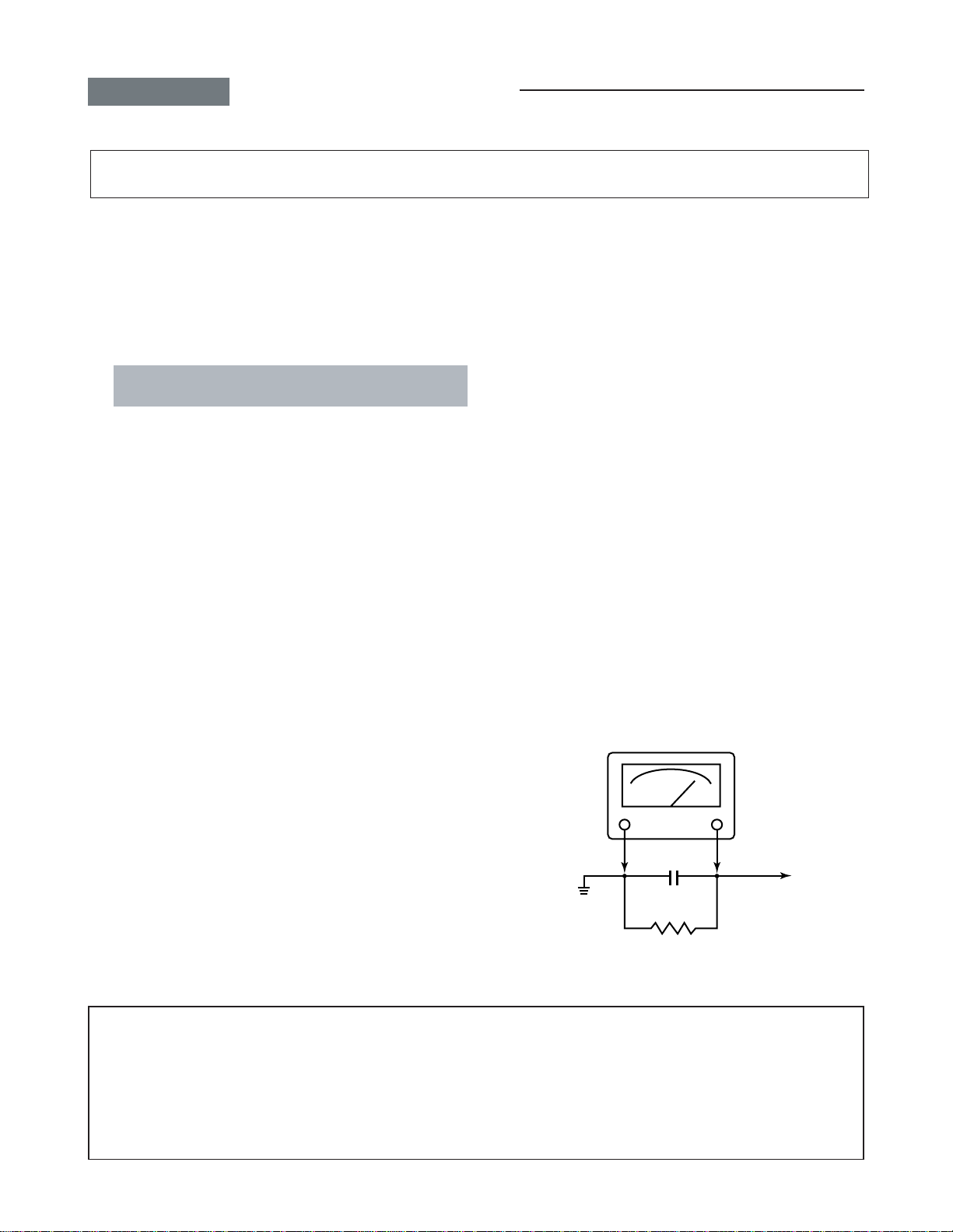
Connect a 1500 ohm 10 watt resistor, paralleled by a 0.15
µ
F, AC type capacitor, between a known good earth ground
(water pipe, conduit, etc.) and the exposed metallic parts,
one at a time. Measure the AC voltage across the combination of 1500 ohm resistor and 0.15 µF capacitor. Re-
verse the AC plug at the AC outlet and repeat AC voltage
measurements for each exposed metallic part. Voltage
measured must not exceed 0.675 volts rms. This corresponds to 0.45 milliamp. AC. Any value exceeding this limit
constitutes a potential shock hazard and must be corrected
immediately.
AC VOLTMETER
0.15 µF
Place this probe on
Good earth ground
such as a water
pipe, conduit, etc.
1500 ohm
10 watt
each exposed
metallic part.
Many electrical and mechanical parts in this chassis have special safety-related characteristics. These characteristics are
often passed unnoticed by a visual inspection and the protection afforded by them cannot necessarily be obtained by using
replacement components rated for higher voltage, wattage, etc. Replacement parts which have these special safety characteristics are identified in this manual and its supplements; electrical components having such features are identified by the
international hazard symbols on the schematic diagram and the parts list.
Before replacing any of these components, read the parts list in this manual carefully. The use of substitute replacement
parts which do not have the same safety characteristics as specified in the parts list may create shock, fire, X-ray radiation or other hazards.
-
3
-
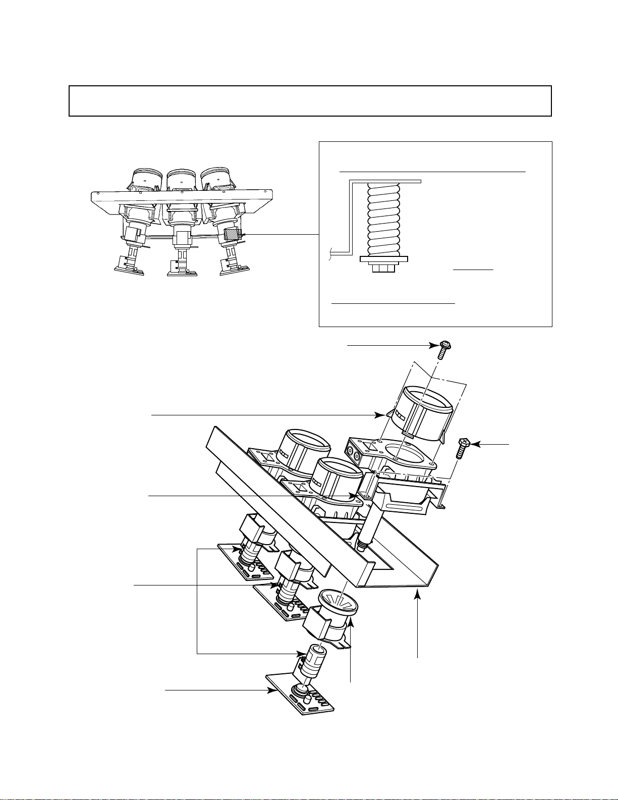
CRT ASSEMBLY REPLACEMENT AND MOUNTING
CAUTION : DO NOT LOOSEN THE HEX HEAD BOLTS WITH SPRINGS (12 PCS), BECAUSE THOSE ARE FOR
SEALING OF CRT COOLANT.
Lens Assembly
R
GB
Attention Serviceman
The Hex Head
Bolts with
Springs. (see
sketch) used on
CRT assembly,
are NOT
Adjustment Screws
DO NOT LOOSEN-FLUID
LEAKAGE WILL OCCUR.
4 Screws
4 Screws
CRT Assembly
S.V.M. Coil
CRT DRIVE Board
Deflection Yoke and Conver Yoke
Lens and Neck Components View
-
4
-
CRT Mounting
TO REMOVE CRT (Same procedure for R, G, B)
1. Remove CRT DRIVE Board, S. V. M. COIL and
DEF. YOKE from CRT.
2. Remove Lens Assembly.
3. Detach CRT Anode Cap from CRT.
4. Remove CRT Assembly from CRT Mounting.
CRT REPLACEMENT (Same procedure for R, G, B)
Reverse the removal procedures except the followings.
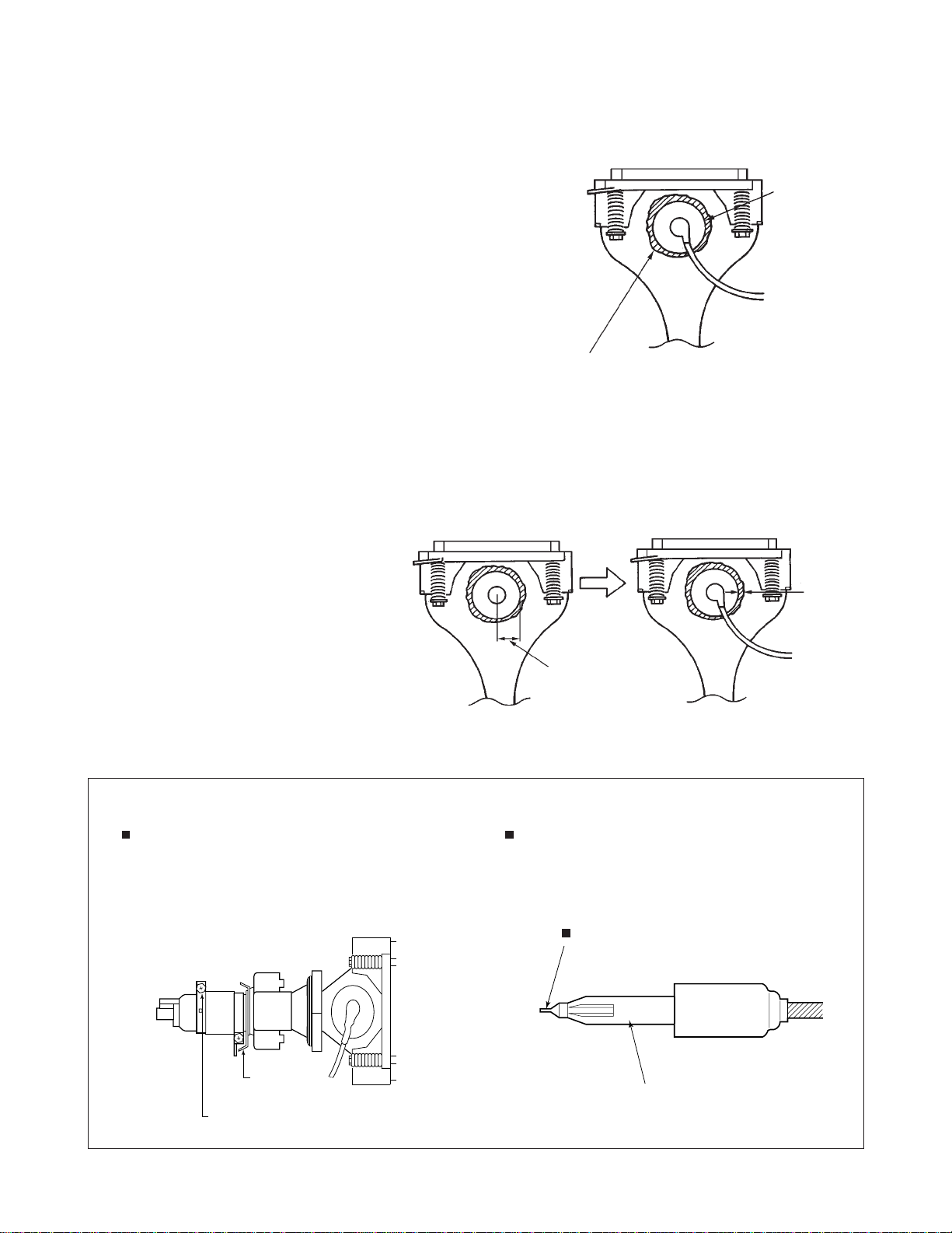
1. Anode Cable should be replaced with new one.
See “SERVICING PRECAUTIONS” shown below.
2. Install silicon (T461B) to the CRT, replace the Anode
cable and put enough silicon again on around the Anode Cap as illustrated.
Anode Cap
CAUTION: Align the Anode cable as illustrated on page
4.
ADJUSTING PROCEDURE IN REPLACING CRT
1. R.G.B. FOCUS ADJUSTMENT (page 7.)
2. PICTURE TILT ADJUSTMENT (page 7.)
3. USER CONVERGENCE CENTER CHECK
(See owner's manual.)
4. CENTERING ADJUSTMENT (page 7.)
5. CONVERGENCE ADJUSTMENT (page 15.)
6. WHITE BALANCE ADJUSTMENT (page 12.)
Adjustments are complete.
Silicon
(On shaded area)
TSE3843W #23960136
2 ~ 5 mm
15 ~ 25 mm
SERVICING PRECAUTIONS
Do not use a magnetized screw driver for screws
of Deflection Yoke and Velocity Modulation Coil to
avoid magnetization of electron gun.
Magnetization of electron gun will degrade basic
function and result in unbalance of right and left
shift of user static convergence, and result in no
variable quantity.
Screw for
D.Y
Screw for SVM coil
When replacing the anode cap assembly (CRT) or
anode lead assembly (F.B.T.), remove the anode
lead holder from old one and attach the holder
again to new anode lead.
Check the point of anode lead in a straight
line, if it is winding, please revise it.
Anode lead holder
-
5
-
WARNING : BEFORE SERVICING THIS CHASSIS, READ THE “X-RAY RADIATION PRECAUTION”, “SAFETY PRECAUTION” AND “PRODUCT SAFETY NOTICE” ON PAGE 3 OF THIS MANUAL.
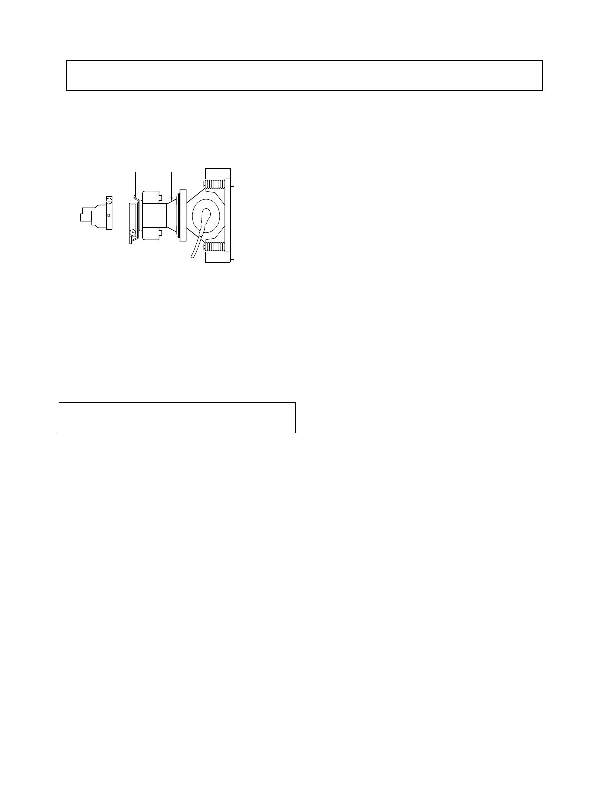
PICTURE TUBE COMPONENTS ADJUSTMENT
DESCRIPTION OF NECK COMPONENTS
Deflection yoke and convergence yoke
The position on the neck is required most front
(CRT funnel side) and the screw is fastened after
rotating yoke adjusting picture tilt.
Centering magnet
After adjusting picture tilt, picture position is finally
fixed by this magnet.
In order to get maximum margin of user convergence control for center of screen, this magnet
have to be used for center convergence adjustment.
PREPARATION
Operate the receiver for at least 5 minutes.
-
6
-
R, G, B FOCUS ADJUSTMENT
1. Before adjusting the R, G, B FOCUS, remove the 4 screws
of Lens Assembly which is fixed on the CRT Assembly.
(See page 4.)
Then turn around the Lens Assembly by 180 to adjust
the fastening screw (Fig. a) and fasten the 4 screws to
secure Lens Assembly.
2. Select the adjustment mode. (See page 10.)
3. Press “7” button to display the built-in cross-hatch.
4. Press “0” and “RTN” buttons to make the picture a single
Red color.
100 button ................ to erase Red color
0 button .................... to erase Green color
RTN button .............. to erase Blue color.
5. Loosen the fasten screw and adjust Red lens focus to best
focusing point of picture center. Then fasten the screw.
(See Fig. a.)
Fig. a
6. Adjust FOCUS VR “R” of FOCUS PACK to find best focusing point of picture center.
7. Repeat steps 3 to 5 for Green and Blue colors.
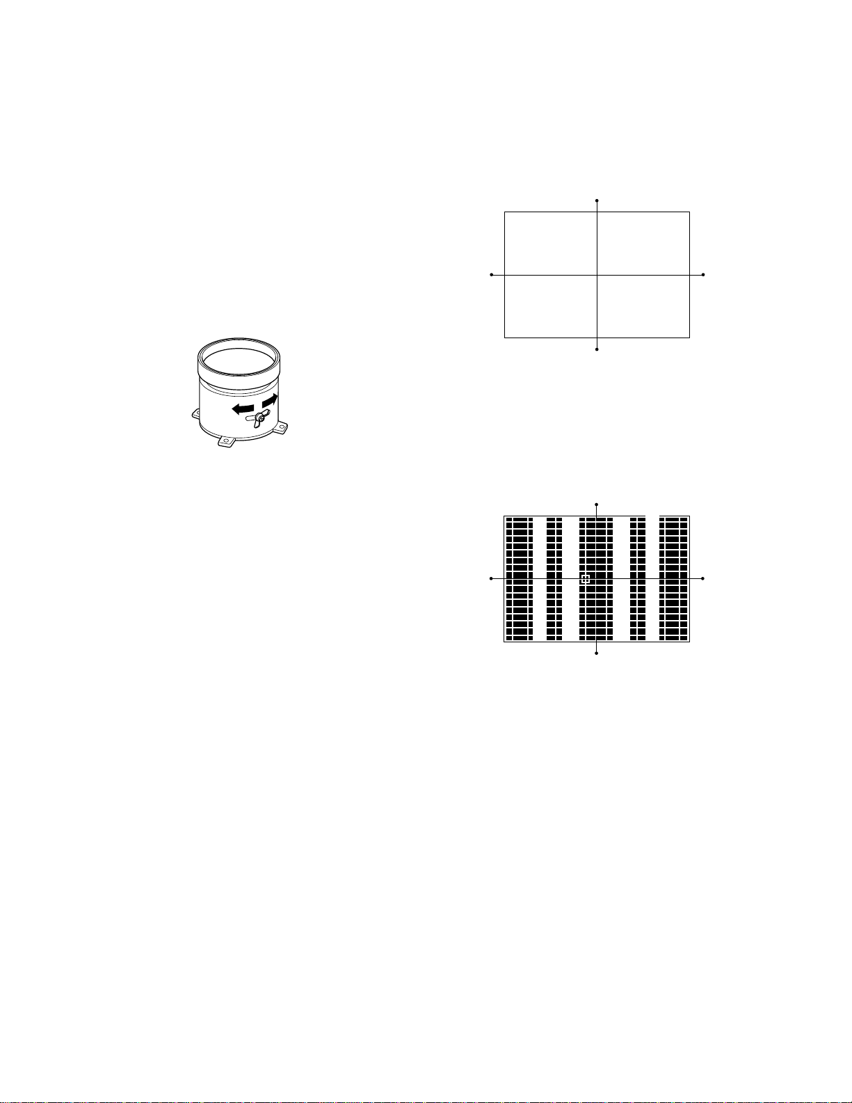
TILT ADJUSTMENT
Rotate R, G, B deflection yoke so that picture becomes horizon, then fasten screw.
CENTERING ADJUSTMENT
1. Stretch a thread between two center of screen edge (top
and bottom, left and right).
2. Receive NTSC.
Then select SERVICE MODE. (See Page 10.)
3. Select CONVERGENCE ADJUSTING mode, and press
"7" button to display the internal net pattern.
Move Cursol and recognize horizontal line indicated Y:4.
This line is vertical center. Push "9" button to display the
vertical stripes, and recognaize horizontal center.
4. Perform VCEN adjustment. (See page 16.)
5. Adjust G centering magnet so that the cross-bar pattern
center comes to screen center.
6. Perform HEIGHT adjustment .
7. Perform VERT. LINEARITY adjustment.
8. Perform WIDTH adjustment. (See page 16.)
9. Check whole quality of green line.
10
. Adjust R, B centering magnet so that the cross-bar pat-
tern center comes to screen center.
-
7
-
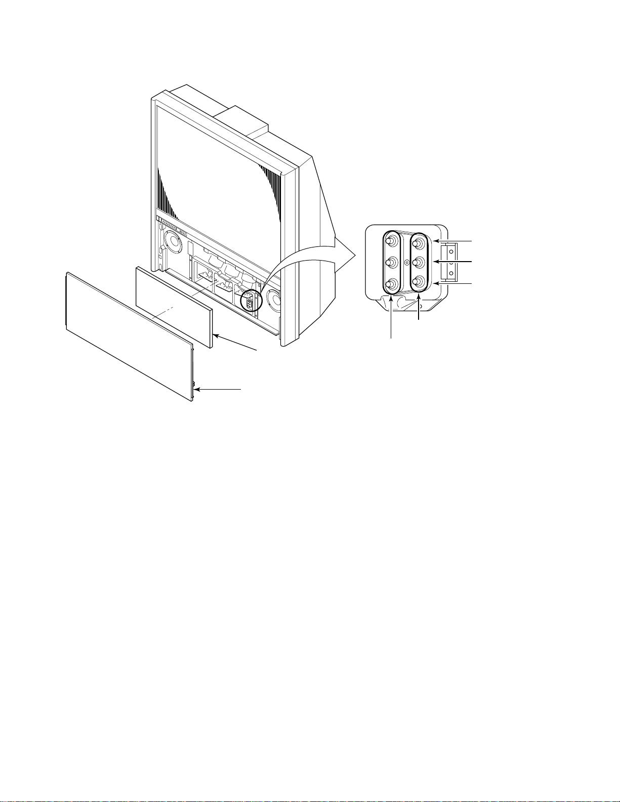
LOCATION OF SCREEN AND FOCUS VR’S
R
G
B
SCREEN
COVER
Speaker grille
FOCUS
-
8
-
REPLACEMENT OF THE CRT
Service parts are provided for each R, G and B.
The contents of the parts are as follows.
RG B
46H84/57H84 HOKUTO
51H84 HITACHI 2334122
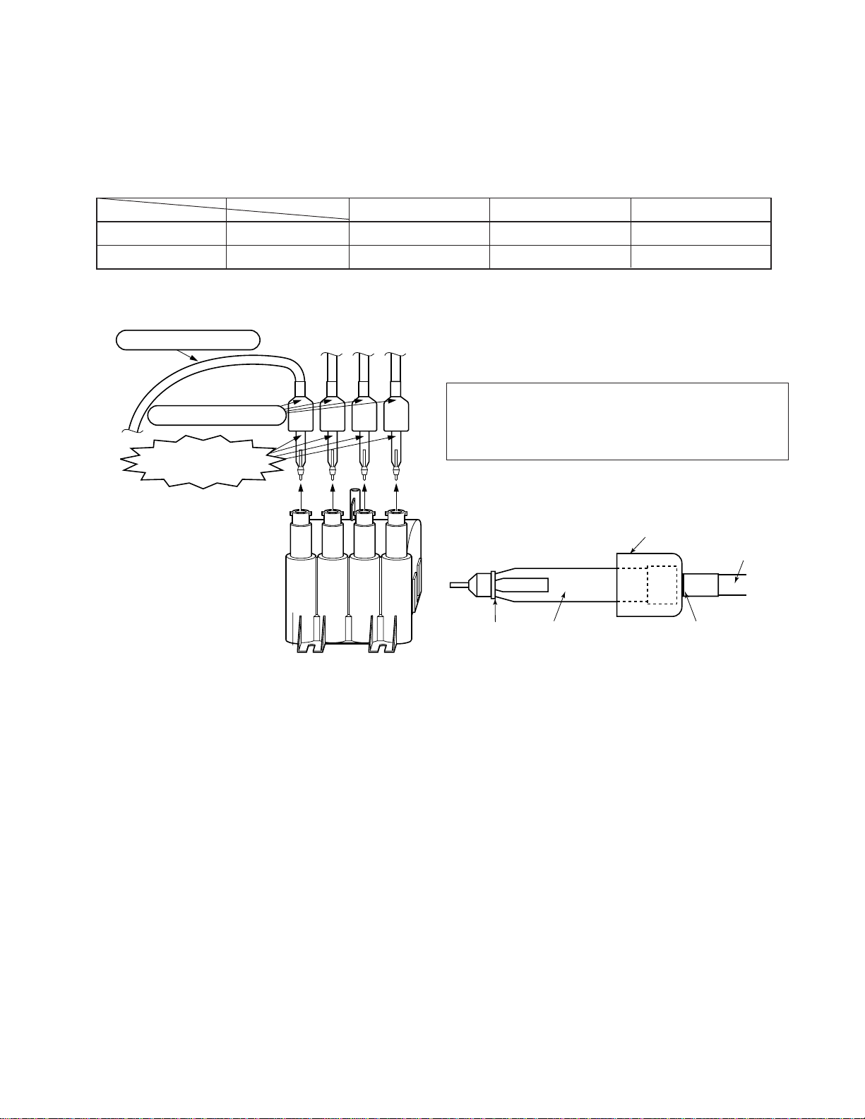
REPLACEMENT OF HIGH VOLTAGE CABLE
ANODE LEAD
RUBBER BOOT
LEAD HOLDER
Z450 TPA5011
Fig. a
2334118
2334119
2334123
1. When replacing Anode Lead or Anode Cap with new one,
remove Lead Holder from old lead as shown in figure
below, and put it on new lead. Do not throw away Lead
Holder.
NOTE : THE LEAD HOLDER IS ATTACHED TO TPA5011
(Z450), BUT IS NOT ATTACHED TO ANODE
LEAD AND ANODE CAP. RUBBER BOOT IS ATTACHED TO ANODE LEAD AND ANODE CAP.
2. Detaching Lead Holder
RUBBER BOOT
LOCK LEAD HOLDER
Fig. b
2334120
2334124
OLD
ANODE LEAD
or
ANODE CAP
Cut here rubber boot
and lead together to
detach Lead Holder.
-
9
-
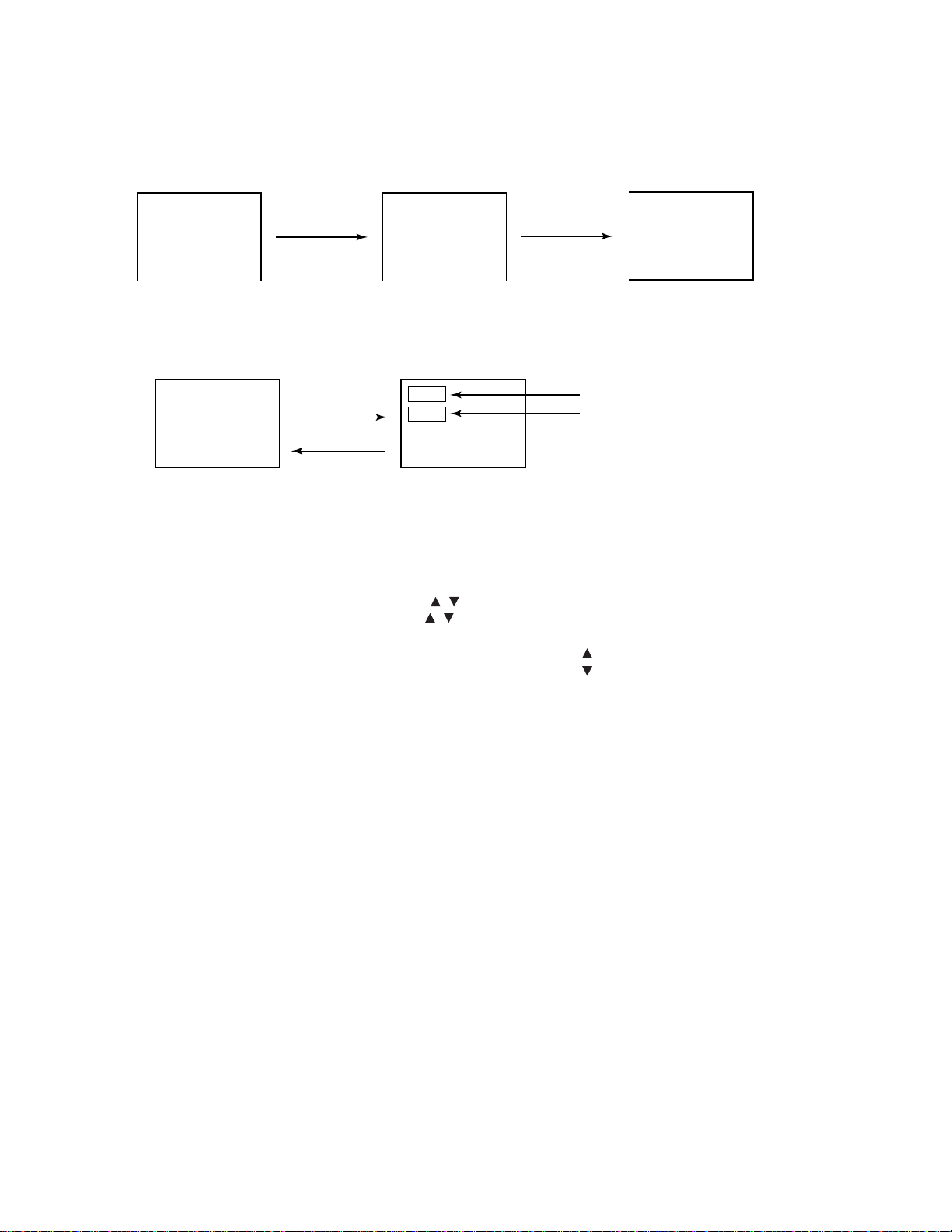
SERVICE MODE
1. ENTERING TO SERVICE MODE
1) Press MUTE button twice
on Remote Control.
MUTE
2. DISPLAYING THE ADJUSTMENT MENU
1) Press MENU button on TV.
Service mode
S
3. KEY FUNCTION IN THE SERVICE MODE
The following key entry during display of adjustment menu provides special functions.
2) Press MUTE button
again to keep pressing.
Adjustment mode
Press
Press
3) While pressing the MUTE button,
press MENU button on TV set.
S
(Service mode display)
Item
Data
Screen adjustment mode ON/OFF: TV (ANT)/VIDEO button (on TV)
Selection of the adjustment items : Channel / (on TV or Remote)
Change of the data value : Volume / (on TV or Remote)
Adjustment menu mode ON/OFF : MENU button (on TV)
Initialization of the memory (QA02) : RECALL+Channel button on TV ( )
Initialization of the self diagnostic data: RECALL+Channel button on TV ( )
“RCUT” selection : 1 button
“GCUT” selection : 2 button
“BCUT” selection : 3 button
“SCNT” selection : 4 button
“COLC” selection : 5 button
Convergence adj : 7 button
Self diagnostic display : 9 button
-
10
-
4. SELECTING THE ADJUSTING ITEMS
1) Every pressing of CHANNEL button in the service mode changes the adjustment items in the order of table-2.
( button for reverse order)
Refer to table-2 for preset data of adjustment mode.
(See SETTING & ADJUSTING DATA on page 20)
5. ADJUSTING THE DATA
1) Pressing of VOLUME or button will change the value of data in the range from 00H to FFH. The variable range
depends on the adjusting item.
6. EXIT FROM SERVICE MODE
1) Pressing POWER button to turn off the TV once.
INITIALIZATION OF MEMORY DATA OF QA02
After replacing QA02, the following initialization is required.
1. Enter the service mode, then select any register item.
2. Press and hold the RECALL button on the Remote, then press the CHANNEL button on the TV. The initialization of QA02
has been complated.
3. Check the picture carefully. If necessary, adjust any adjustment item above.
Perform “Programming Channel Memory” on the owner's manual.
CAUTION: Never attempt to initialize the data unless QA02 has been replaced.
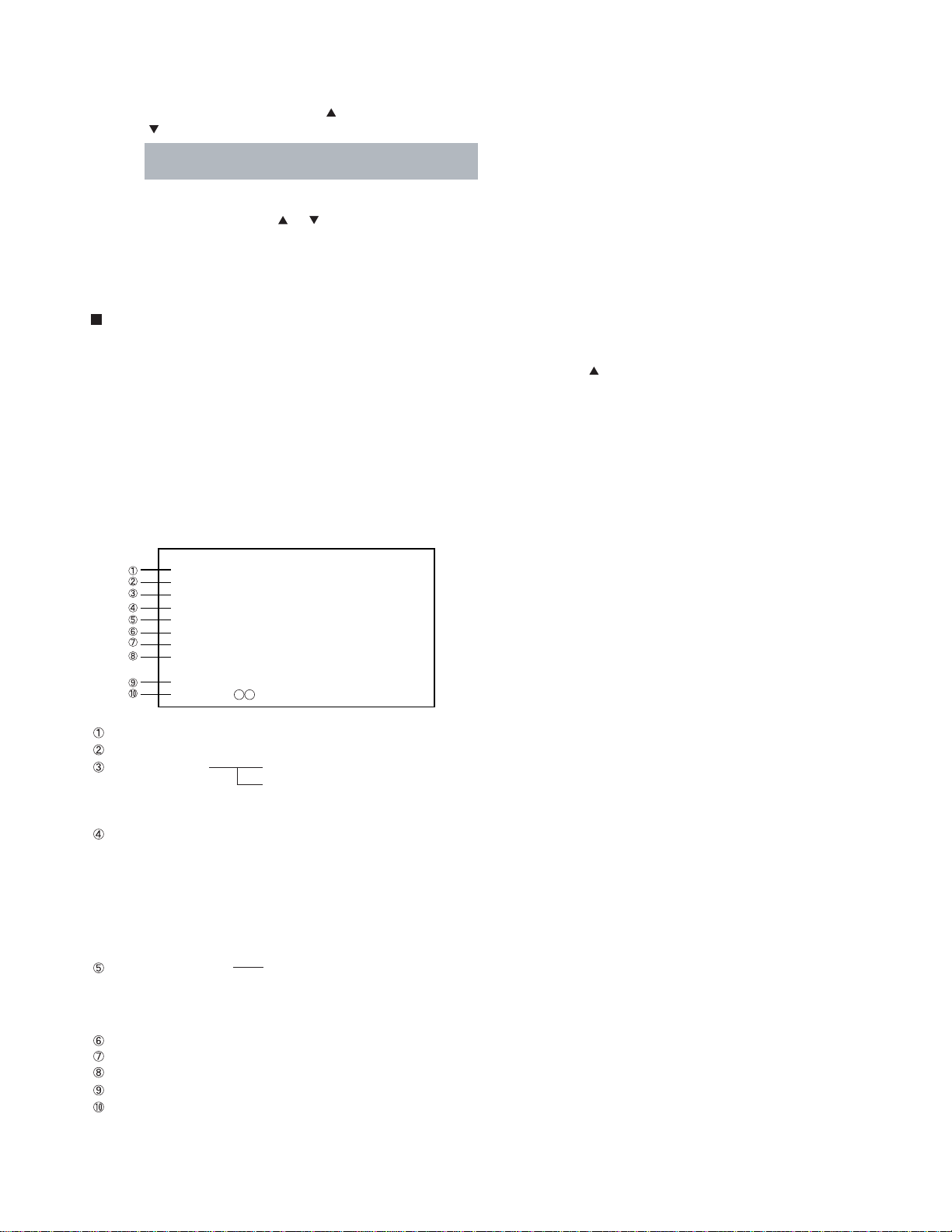
7. SELF DIAGNOSTIC FUNCTION
1) Press “9” button on Remote Control during display of adjustment menu in the service mode.
The diagnosis will begin to check if interface among IC’s are executed properly.
2) During diagnosis, the following displays are shown.
SELF CHECK
NO. 23 * * * * * *
POWER : 000
BUS LINE : OK
BUS CONT : OK
BLOCK : MAIN SUB
SET ID : 01
EEP VER : 02
OPT1 : 05 OPT2 : 70
HDMI
NO * * * * * * * *
ERR CODE :
Part number of microprocessor (QA01)
Operation number of protection circuit (current limiter) . . . . “000” is normal.
BUS line check “OK” ................... Normal
“SCL-GND” or “NG” ........... SCL-GND short circuit
“SDA-GND” or “NG” ........... SDA-GND short circuit
“SCL-SDA” or “NG” ............ SCL-SDA short circuit
BUS line ACK (acknowledge) check
“OK” ..................... Normal
Display of Location Number . . . . NG
(Display example)
“QA02 NG”, “H001 NG”, “Q501 NG” etc.
Note: The indication of failure place is only one place though failure places are plural. When
repair of a failure place finishes, the next failure place is indicated. (The order of priority of
indication is left side.)
Sync. signal check Green display ..... Normal
Red display ........ NG
MAIN ........ Main sync
SUB .......... Sub sync (when turn on the PIP)
ID code for TV Set
Version of "EEP"
Data for "OPT"
Part number of HDMI microprocessor
HDMI error code
-
11
-
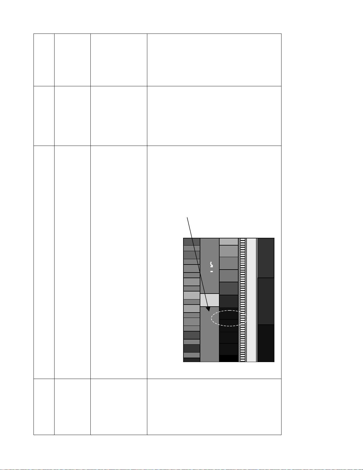
ADJUSTMENT
SPECIFICATION
ELECTRICAL ADJUSTMENT
10500k+0UV
Same spec is ap-
plied on dark area
and bright area.
1
+
-
5TH
BAR SUNK
SIGNAL
White luster signal
(Valuable input level)
CHANNEL 3
SUB-BRIGHT
SIGNAL
5th bar sunk
PROCESS INSTRUCTIONS
ADJUSTING
1. Heart run minimum 15minutes.
2. Go into screen adjustment mode.
ITEM
SCREEN ADJUST
Adjust Focus pack Screen VR of Red, Green, and Blue by looking directly into each
CRT and adjusting each screen VR until CRT is just lit on left side of CRT.
area.
BLUE DRIVE, RED BIAS and BLUE BIAS.
Adjust RED DRIVE, BLUE DRIVE for bright area, and adjust RED BIAS and BLUE
BIAS for dark area.
1. Adjust white luster level to get 4.3cd/m2 on dark area, and get 264.3cd/m2 on bright
2. Using the data up and down keys, cycle through the adjustments for RED DRIVE,
WHITE BARANCE
ADJUSTMENT
3. Continue to make adjustments color temperature to spec on each area.
1. Receive channel 3 Sub-Bright pattern.
2. Go into BRTC of service mode.
3. Press DATA UP/DOWN to adjust Sub-Bright level to spec.
SUB-BRIGHT
ADJUSTMENT
-
12
-
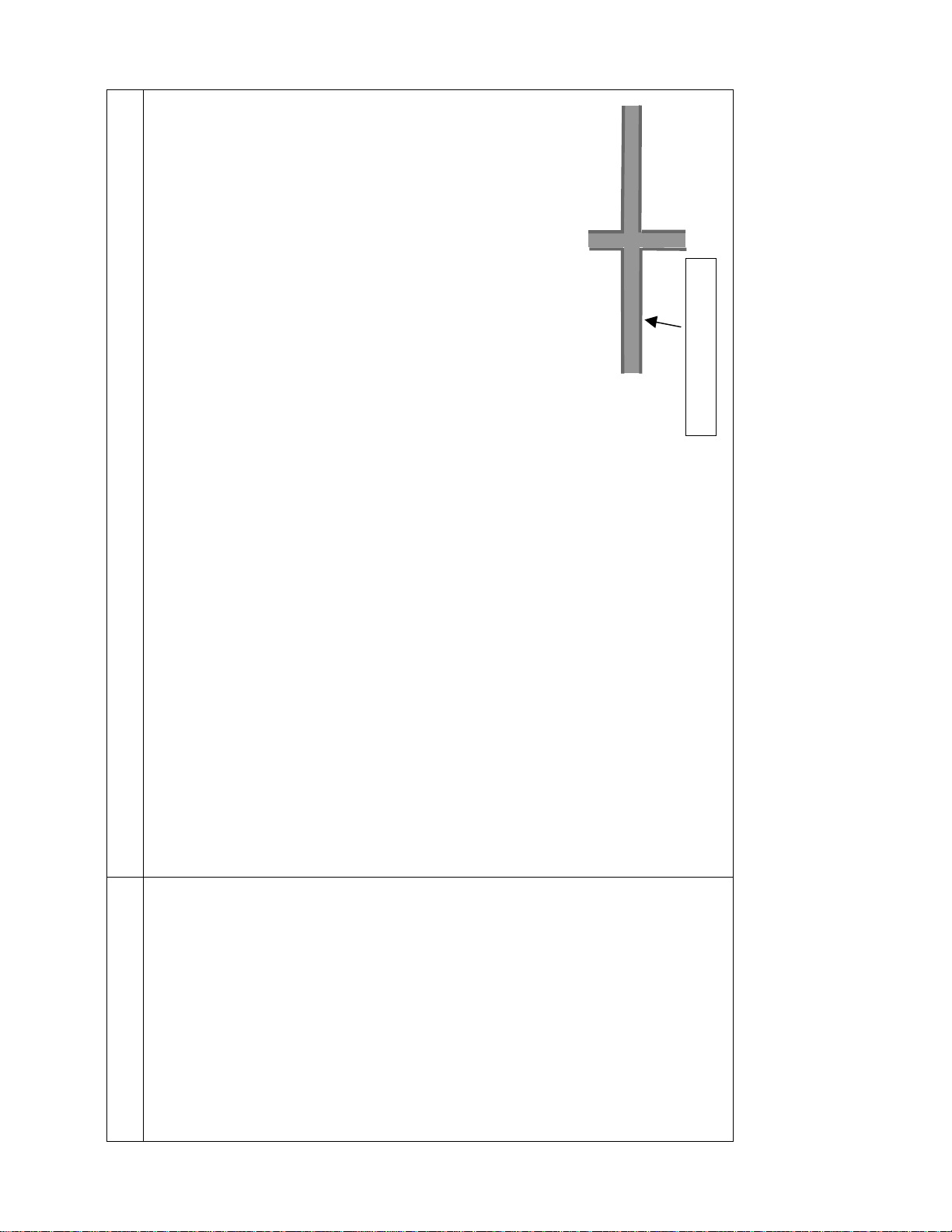
G Dot cross (NTSC)
B Dot cross (NTSC)
Electrical Focus : R Dot cross (NTSC)
• User Adjustment : SPORTS (CONTRAST MAX, BRIGHTNESS CENTER)
• Adjust after Centering Magnet adjusts.
• Signal : Lens Focus : R Dot cross (NTSC)
ADJUSTMENT METHOD
(Condition)
G Dot cross (NTSC)
B Dot cross (NTSC)
1) Rough Adjust the lens focus and electrical focus of each color(R, G, B).
(Adjustment)
1. Common Items
Adjust Green electrical focus VR on focus pack (Z410) for best center focus.
1) Receive green single color by shielding jig.
2) Receive the Dot Cross pattern.
3) Adjust Green electrical focus.
2. Green Adjustment
Red flare width : 1mm
If the focus blur on screen center and circumference, adjust the electrical focus is best point on all of screen.
Receive the Dot Cross pattern. Adjust Green lens for best center focus.
Green lens focus adjustment target
Dot-cross has red flare (red flare width :1mm)
4) Adjust Green lens focus.
5) Repeat (3)~(4),and adjust best focus point.
ITEM
FOCUS ADJUSTMENT (1/2)
Focus Adjustment
-
13
-
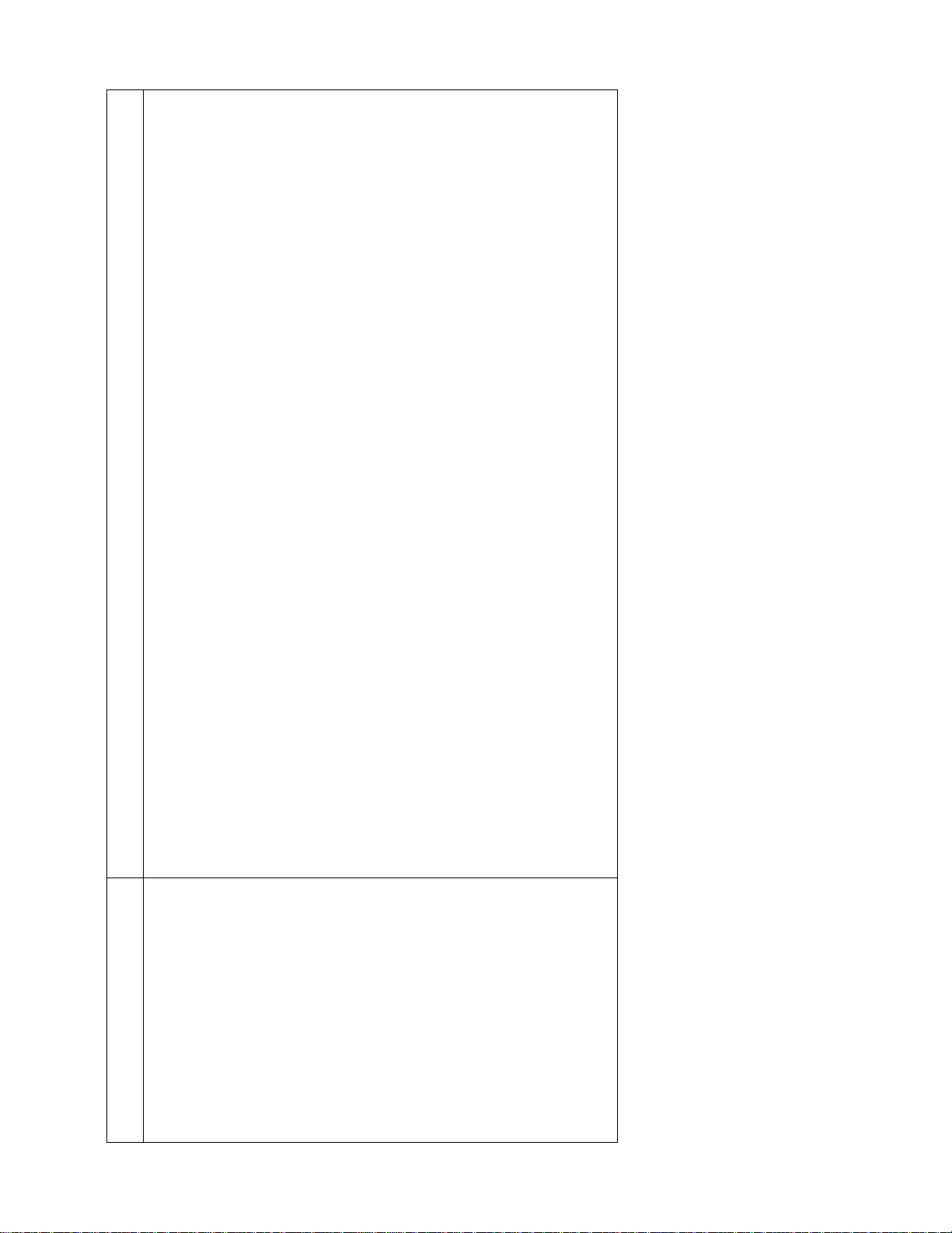
Adjust Red electrical focus VR on focus pack (Z410) for best center focus.
Receive the Dot Cross pattern. Adjust Red lens for best center focus.
1) Receive Red single color by shielding jig.
2) Receive the Dot Cross pattern.
3) Adjust Red electrical focus.
4) Adjust Red lens focus.
ADJUSTMENT METHOD
3. Red Adjustment
ITEM
FOCUS ADJUSTMENT (2/2)
Focus Adjustment
5) Repeat (3)~(4),and adjust best focus point.
1) Receive Blue single color by shielding jig.
2) Receive the Dot Cross pattern.
4. Blue Adjustment
3) Adjust Blue electrical focus.
Adjust Blue electrical focus VR on focus pack (Z410) for best center focus.
(The Brightness is minimum point of Blue.)
-
14
Receive the Dot Cross pattern. Adjust the Blue lens for best center focus.
After easy lens adjustment, turn to right side lens focus screw,
and so dot-cross has flare.
Next turn left focus screw, so flare disappears in Dot-Cross and Dot-Cross become blur.
This point is blue lens focus adjustment target. (flare disappear and become blur)
4) Adjust Blue lens focus.
-

CONVERGENCE ADJUSTMENT
1. Receive NTSC signal.
2. Enter to the service mode. (See Page 10.)
RCUT
40H
3. Press "7" button to enter the convergence adjusting mode,
and the internal net pattern will be displayed. Then, press
"9" button to display veritcal stripes.
4. Select the point and the color by pressing following buttons. (Cursor should be blinking.)
"2", "8", "4", "6" : To select point
"3" : To select color
5. Then press "5" button, and adjust the convergence by
pressing following buttons. (Cursor should not be
blingking.)
"2", "8", "4", "6" : To adjust convergence
"3" : To select color
6. Repeat from steps 3 to 4 until the convergence and the
geometry become fine. (See Page 14.)
7. Press "7" button to memorize the adjusted data.
8. Message of "PLEASE PUSH TOUCH FOCUS" will be displayed, and press TOUCH FOCUS button which is located
on the front panel.
9. TOUCH FOCUS CALIBRATION will start.
10. Soon message of "CALIBRATION FINISHED" will be displayed, and then a normal picture will be displayed.
11. Then push TOUCH FOCUS button again, and confirm that
the convergence does not change.
EXPLANATION OF KEY-FUNCTION IN THE CONVERGENCE ADJUSTMENT MODE
Load BACK UP DATA: 1 button
Up : button
Selet Green color:
Left : button
Blinking of cursor ON/OFF: 5 button
Right:
Adjust mode ON/OFF: 7 button
Down: 8 button
Vertical stripe ON/OFF 9 button
Erase Green line: 0 button
Erase Red line: 100 button
Erase Blue line: ENT button
Note: The following message will appear while pressing
"1" button.
ENTER: TO LOAD BACKUP DATA
MUTE: TO LOAD INITIAL DATA
EXIT: TO EXIT
BACKUP DATA sets in factory by performing
CALIBRATION. BACKUP DATA updates by performing CALIBRATION again. INITIAL DATA
uses the seed data on this model. Thus, it cannot
updates. INITIAL DATA is not adjusted. Therefore, convergence data operates incorrectly. Normally, BACKUP DATA operates as base data on
this model. If BACKUP DATA is incorrectly operated, INITIAL DATA is operated instead of BACKUP DATA.
2
3
button
4
6
button
Note: If message of "TOUCH FOCUS ERROR" is displayed,
1) Check the connection between four sensors and
Convergence Unit.
2) Check the geometry of internal net pattern. (See Page
14.)
If any problem cannnot be found, hardware might have
problem.
-
15
-
 Loading...