

Toshiba 44NHM84 Schematic

SERVICE MANUAL
FILE NO. 050-200423
44NHM84
PRINTED IN JAPAN, Dec., 2004
- 2 -
SAFETY PRECAUTIONS
Many electrical and mechanical parts in this chassis have special safety-related characteristics. These parts are identified by in
the Schematic Diagram and Replacement Parts List.
It is essential that these special safety parts should be replaced with the same components as recommended in this manual to
prevent X-RADIATION, Shock, Fire, or other Hazards.
Do not modify the original design without permission of manufacturer.
General Guidance
An lsolation Transformer should always be used during
the servicing of a receiver whose chassis is not isolated from
the AC power line. Use a transformer of adequate power rating
as this protects the technician from accidents resulting in
personal injury from electrical shocks.
It will also protect the receiver and it's components from being
damaged by accidental shorts of the circuitary that may be
inadvertently introduced during the service operation.
If any fuse (or Fusible Resistor) in this monitor is blown, replace
it with the specified.
When replacing a high wattage resistor (Oxide Metal Film
Resistor, over 1W), keep the resistor 10mm away from PCB.
Keep wires away from high voltage or high temperature parts.
Due to high vacuum and large surface area of picture tube,
extreme care should be used in handling the Picture Tube.
Do not lift the Picture tube by it's Neck.
Leakage Current Cold Check(Antenna Cold Check)
With the instrument AC plug removed from AC source,
connect an electrical jumper across the two AC plug prongs.
Place the AC switch in the on positioin, connect one lead of
ohm-meter to the AC plug prongs tied together and touch other
ohm-meter lead in turn to each exposed metallic parts such as
antenna terminals, phone jacks, etc.
If the exposed metallic part has a return path to the chassis, the
measured resistance should be between 1MΩ and 5.2MΩ.
When the exposed metal has no return path to the chassis the
reading must be infinite.
An other abnormality exists that must be corrected before the
receiver is returned to the customer.
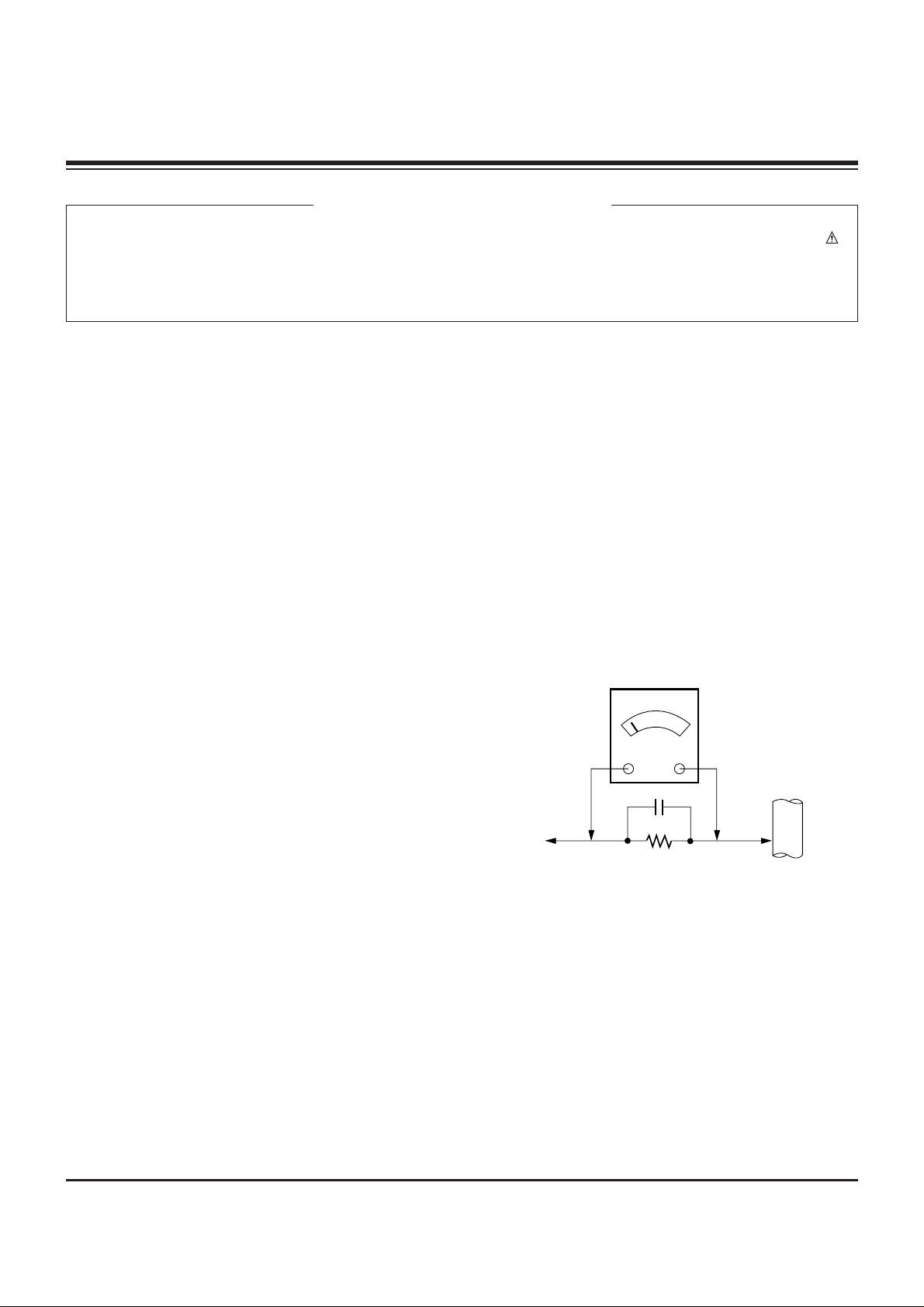
Leakage Current Hot Check (See below Figure)
Plug the AC cord directly into the AC outlet.
Do not use a line Isolation Transformer during this check.
Connect 1.5K/10watt resistor in parallel with a 0.15uF capacitor
between a known good earth ground (Water Pipe, Conduit, etc.)
and the exposed metallic parts.
Measure the AC voltage across the resistor using AC
voltmeter with 1000 ohms/volt or more sensitivity.
Reverse plug the AC cord into the AC outlet and repeat AC
voltage measurements for each esposed metallic part. Any
voltage measured must not exceed 0.75 volt RMS which is
corresponds to 0.5mA.
In case any measurement is out of the limits sepcified, there is
possibility of shock hazard and the set must be checked and
repaired before it is returned to the customer.
Leakage Current Hot Check circuit
CANADA: LG Electronics Canada, Inc. 550 Matheson
Boulevard East Mississauga, Ontario L4Z 4G3
USA : LG Customer Interactive Center
P.O.Box 240007, 201 James Record Road Huntsville,
AL 35824
Digital TV Hotline 1-800-243-0000
1.5 Kohm/10W
To Instrument's
exposed
METALLIC PARTS
Good Earth Ground
such as WATER PIPE,
CONDUIT etc.
AC Volt-meter
IMPORTANT SAFETY NOTICE
0.15uF

TABLE OF CONTENTS
SPECIFICATIONS ...................................................................................................... 4
DESCRIPTION OF CONTROLS ................................................................................ 5
ADJUSTMENT INSTRUCTION................................................................................ 12
PRINTED CIRCUIT BOARDS .................................................................................. 18
BLOCK DIAGRAM ................................................................................................... 29
EXPOLODED VIEW ................................................................................................ 30
EXPOLODED VIEW PARTS LIST......................................................................... 31
SCHEMATIC DIAGRAM .......................................................................................... 32
ELECTRICAL REPLACEMENT PARTS LIST.......................................................... 48
- 57 -
- 3 -

- 4 -
Product Specifications
Model
44NHM84 Horizontal Size (Inches) 39.92
Height (Inches) 29.19
Depth (Inches) 14.29
Weight (lbs.) 59.5
Power Requirement AC 120V, 60Hz
Television System NTSC, External STB is required for the reception of Satellite broadcasting or Digital Cable
broadcasting
Television Channels VHF: 2 - 13
UHF: 14 - 69
CATV: 1 - 125
Power Consumption (W) 230W
Antenna 75 ohm External Terminal for VHF/UHF
Audio Output (W) 12W x 2
External Input/Output Ports A/V input (3 set)
Monitor out (1 set)
S-Video input (2)
COLORSTREAM HD input (2 set)
RGB input (1)
DVI input (1)
RGB/DVI audio input (1 set)
Variable audio output (1 set)
Audio center mode input (1)
Upgrade port (1)
RF input (1)
• This model complies with the specifications listed below.
• Designs and specifications are subject to change without notice.
• This model may not be compatible with features and/or specifications that may be
added in the future.
SPECIFICATIONS
- 5 -
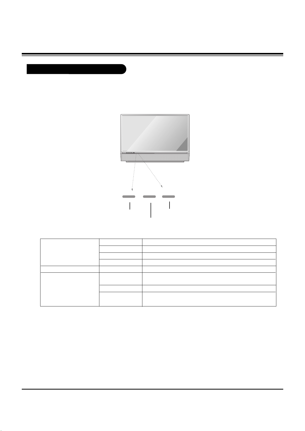
Function Status Indicators
Lamp indicator, operation indicator, and temperature indicator located below the front panel
controls, reveal the operating status of the DLP projection TV.
Operation Indicator
Lamp Indicator
Temperature Indicator
Off Power cord is not connected.
Red Power Cord is connected, TV is in standby mode.
Green TV turns on.
Orange (flashing) Preparing operation in standby mode.
Green (flashing) The lamp cover is not closed.
Orange The projection TV is overheating. Check the blocked vents of
the projection TV .
Red The projection TV shut down due to overheating.
Red (flashing) The projection TV shut down due to the cooling fan trouble.
Contact an authorized service center.
Operation Indicator
Lamp Indicator
Temperature Indicator
DESCRIPTION OF CONTROLS
- 6 -
AUDIO
CENTER
MODE IN
DVI INPUT
COLORSTREAM HD
INPUT2 INPUT1
PR
PB
Y
PC/DTV
(XGA/
480p/
720p/
1080i)
PC/DTV
(XGA/
480p/
720p/
1080i)
RGB INPUT
UPGRADE PORT
RGB/DVI INPUT
(R)
(L)
AUDIO
(R)
(L)
AUDIO
(R)
(L)
AUDIO
VARIABLE
AUDIO OUT
MONITOR
OUT
VIDEO
INPUT 2
VIDEO
INPUT 1
S-VIDEO
(R)
(L)
AUDIO
VIDEO
MONO
+75 Ω
ANT IN
DTV /DVD
(480i/
480p/
720p/
1080i)
(480i/
480p/
720p/
1080i)
Mini glossary
JACK A connection on the back of a TV, VCR, or any other A/V device. This includes the RF jack and the Audio/Video jacks that are
color-coded.
SIGNAL Picture and sound traveling through cable, or over the air, to your television screen.
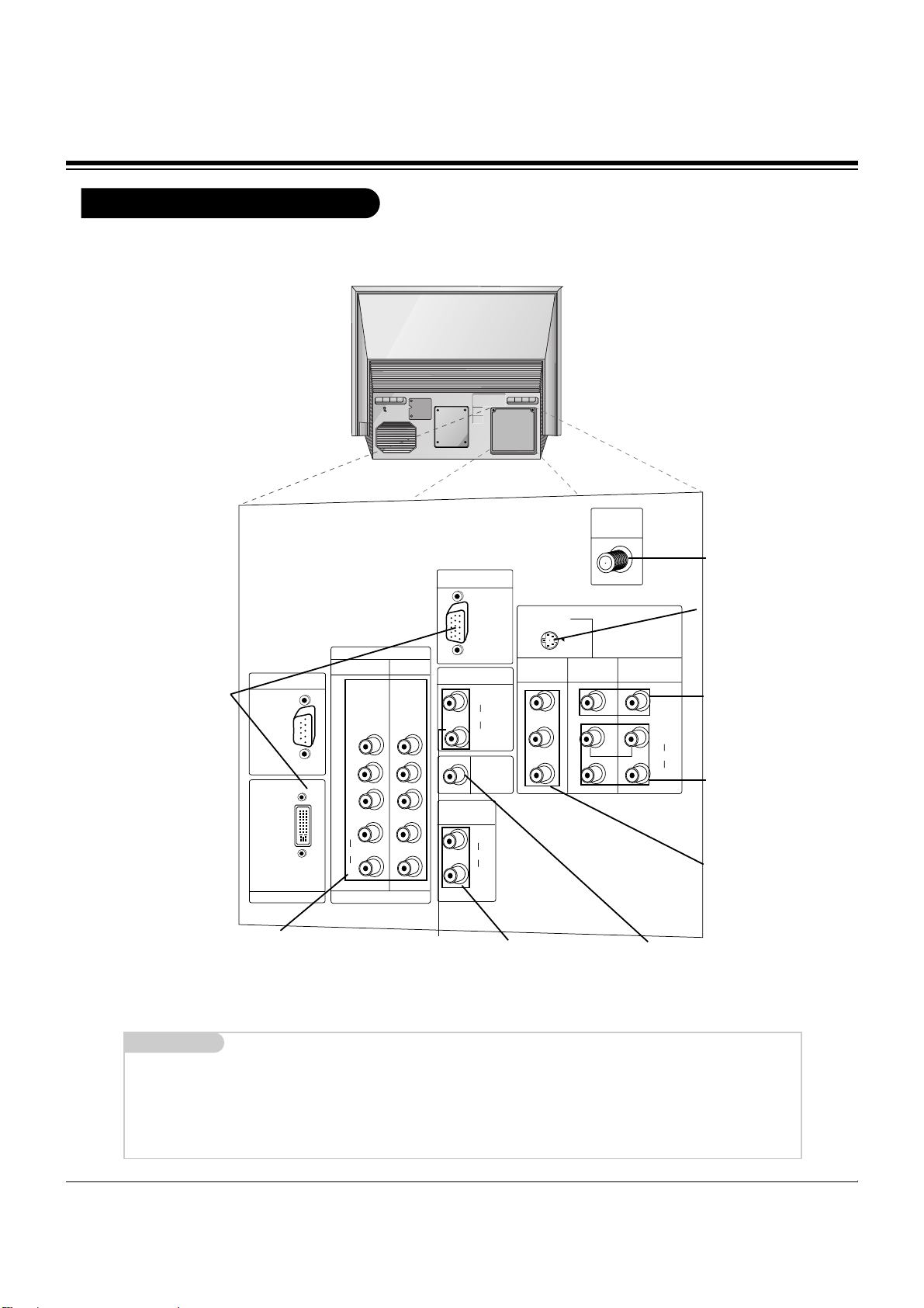
Rear Connections Panel
S-VIDEO In
A connection available with
some high-end equipment
that provides even better picture quality for Video 2.
Variable Audio Out
Used to connect either
an external amplifier, or
add a sub-woofer to your
surround sound system.
RF Connector: Antenna
Used to connect analog
cable or antenna signals
to the television, either
directly or through your
cable box.
Video 1 or 2
Connects the video signals from various types
of equipment.
COLORSTREAM HD
Connect a ColorStream HD video/audio
device to these jacks. Refer to your DVD
manual for further information.
Connecting cables and external equipment to your TV.
Monitor Out
Connects to a second TV
or Monitor.
Left/Right Audio
Used for stereo sound
from various types of
equipment.
RGB/DVI Input
Connect the TV output con-
nector from a PC/DTV to
the appropriate input port.
RGB/DVI Input
Used for audio connec-
tions from a PC source or
HD-STB Satellite system.
Audio Center Mode In
Connect to external Dolby
¨
Digital Center “preamp output.”
DESCRIPTION OF CONTROLS
- 7 -
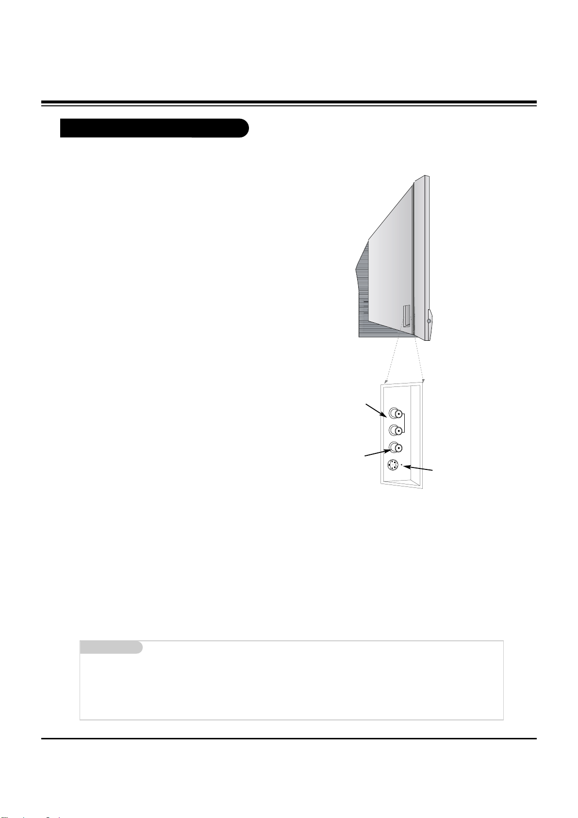
Front Connection Panel
Front A/V Panel
S-VIDEO
VIDEO
FRONT A/V
AUDIO
(R)
(L)/
MONO
There are four jacks on the left front of your projection TV
that make connecting Audio/Video devices like video games
and camcorders very simple.
The jacks are like those found on the back jack connection
panel. This means that most equipment that connects to
those types of jacks on the rear jackpack, may be connected to the front connection panel.
To use the front jacks as the signal source, select them
using Main Input menu as described on page 27. They will
be named “Front Video” in the Main Input menu.
Left/Right Audio
Used for stereo
sound from various
types of equipment.
Video
Connects the video
signals from any piece
of equipment.
S-Video
A connection available on
some very high-end equipment that provides better
picture quality than video
input.
If you input both Front Video and SVideo, only the S-Video will work.
If you’re connecting a video game
device, make sure to change the
picture settings with the Picture Mode
option in the Video menu.
Mini glossary
A/V CABLES Audio/Video cables. Three cable connectors—Right audio (red), Left audio (white), and Video (yellow). A/V cables are used
for stereo playback of videocassettes and for higher quality picture and sound from other A/V devices.
A/V DEVICE Any device that produces video or sound (VCR, DVD, cable box, or television).
W
W
DESCRIPTION OF CONTROLS
- 8 -
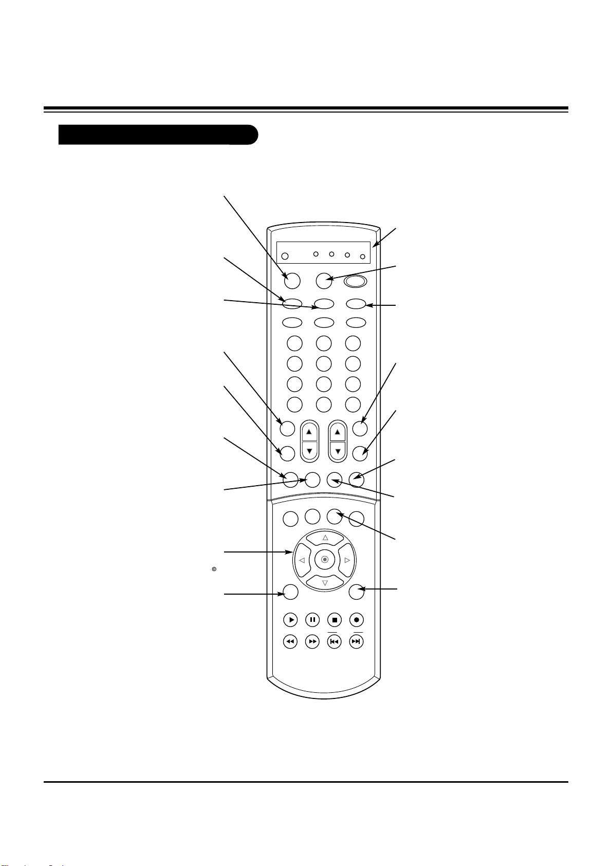
Remote Control Functions in TV Mode
1 2 3
4 5 6
7 8 9
0
TV
MODE
LIGHT
POWER
TV/VIDEO
DVI
RGB
VCR
CABLE
DVD
SAT
MUTE
SWAPPIPCH- PIPCH+
PIP
PIC SIZE
REC
STOP
PAUSE
REW
PLAY
FF
MENU EXIT
CC FREEZE
PIP INPUT
VOL
CH
SURF
SAP
VIDEO
C/S HD2C/S HD1
FRONT
SKIP
ENTER
CH RTN
SURF
Scrolls the Surf channel list.
MENU
Brings up the main
menu to the screen.
EXIT
Clears all on-screen displays and returns to TV
viewing from any menu.
FREEZE
Captures and freezes the currentlyviewed main picture.
VIDEO
Adjusts the factory preset
picture according to the
room.
PIPCH+
Changes to next higher PIP
channel.
SWAP
Switches the picture from
PIP, POP, or twin picture to
the main screen.
MUTE
Switches the sound on or off
THUMBSTICK
Allows you to navigate the on-screen
menus and to adjust the system set-
tings and preferences, by moving to an
option with
F G
and selecting the high-
lighted option with .
TV/VIDEO
Selects: Analog, Video1,
Video2, Front video,
ColorStream HD1-2, RGB, and
DVI input sources.
MODE
Selects the remote operating
mode: TV, VCR, Cable, DVD
and Satellite. Select other oper-
ating modes, for the remote to
control external devices.
FRONT
Selects the front video signal if
a device, such as a camcorder
or game player, is connected
to the front video input jack.
DVI
Selects: DVI-DTV and DVIPC input sources.
SAP
Selects: Mono, Stereo, and
SAP.
PIPCH-
Changes to next
lower PIP channel
PIP
Toggles between PIP, POP
(Picture-out-of-Picture) and
Twin picture mode.
LIGHT
Illuminates the remote control keys.
INDICATOR LIGHTS
Show active remote mode
every time any button is
pressed.
D
E
DESCRIPTION OF CONTROLS
- 9 -
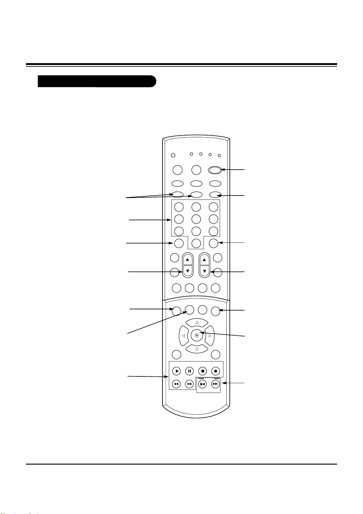
Remote Control Functions in TV Mode
1 2 3
4 5 6
7 8 9
0
TV
MODE
LIGHT
POWER
TV/VIDEO
DVI
RGB
VCR
CABLE
DVD
SAT
MUTE
SWAPPIPCH- PIPCH+
PIP
PIC SIZE
REC
STOP
PAUSE
REW
PLAY
FF
MENU EXIT
CC FREEZE
PIP INPUT
VOL
CH
SURF
SAP
VIDEO
C/S HD2C/S HD1
FRONT
SKIP
ENTER
CH RTN
POWER
Turns your TV or any other
programmed equipment on
or off, depending on mode.
CHANNEL UP/DOWN
Scrolls through available channels in CH. Scan memory.
NUMBER KEYPAD
For direct channel selection and
programming functions.
ENTER
When in the menu system
and other on-screen displays, selects highlighted
options.
RECORD, PAUSE, REW,
FFWD, PLAY, STOP
Control the functions on your VCR.
VOLUME UP/DOWN
Increases/decreases the sound
level.
PIC SIZE
Changes the screen format or
aspect ratio.
SKIP
Playing CDs: Selects
songs.
Playing DVDs: Selects
movie chapters.
C/S HD1,HD2
Selects ColorStream HD signal
sources, such as DVD or HD receiver.
ENTER
When in the menu system and
other on-screen displays,
selects highlighted options.
CH RTN
Tunes to the last channel
viewed.
CC
Selects a closed caption mode
for displaying captioning infor-
mation if available on program.
PIP INPUT
Selects the input source for the
sub picture.
RGB
Selects: RGB-DTV and
RGB-PC input sources.
DESCRIPTION OF CONTROLS
- 10 -
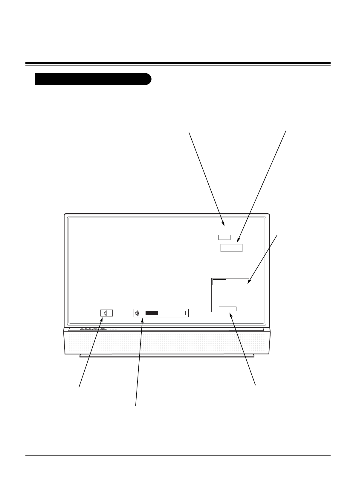
On-Screen Displays
This page describes your on-screen display and information banner options.
10
AM 3:00
TV 13
MONO
TV 6
Main Channel Display
Displays current channel number.
Channel Label
If a channel label has been
set, then it will appear here.
PIP Display
This display
appears when
PIP is active.
Volume
Volume level is displayed while
adjusting the sound.
Mute
Appears
when sound
is muted.
Time
Appears when
pressing the
enter button.
ABC
DESCRIPTION OF CONTROLS
 Loading...