

Page 1
SERVICE MANUAL
(*1), as indicated by the underlined serial number.
LCD Color Television
40LV655P
Ver. 2.01
This model is classified as a green product
This Service Manual describes replacement parts for the green product. When repairing this
green product, use the part(s) described in this manual and lead-free solder (*2).
For (*1) and (*2), refer to GREEN PRODUCT PROCUREMENT and LEAD-FREE
SOLDER.
© TOSHIBA CORPORATION
Page 2
IMPORTANT NOTICE
WARNING:
You are requested that you shall not modify or alter the information or data
provided herein without prior written consent by Toshiba. Toshiba shall not
be liable to anybody for any damages, losses, expenses or costs, if any,
incurred in connection with or as a result of such modification or alteration.
THE INFORMATION OR DATA HEREIN SHALL BE PROVIDED "AS IS"
WITHOUT ANY WARRANTY OF ANY KIND, EITHER EXPRESS OR IMPLIED
WARRANTY OF MERCHANTABILITY AND FITNESS FOR A PARTICULAR
PURPOSE.
Toshiba shall not be liable for any damages, losses, expenses or costs, if
any, incurred in connection with or as a result of use of any information or
data provided herein.
Page 3
IMPORTANT NOTICE
up windows are limited by
User's Guide
Contents:
Install Autodesk DWF Viewer
Internet Explorer Settings
Operating Environment
Functions Provided on Each Drawing Page
Using with Network
Install Autodesk DWF Viewer
Autodesk DWF Viewer is necessary to view drawings and to activate the functions of this system. Please
download and install.
Internet Explorer Settings
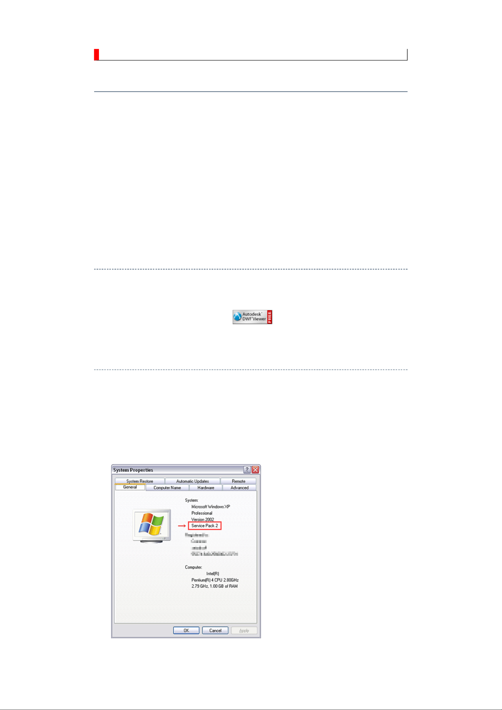
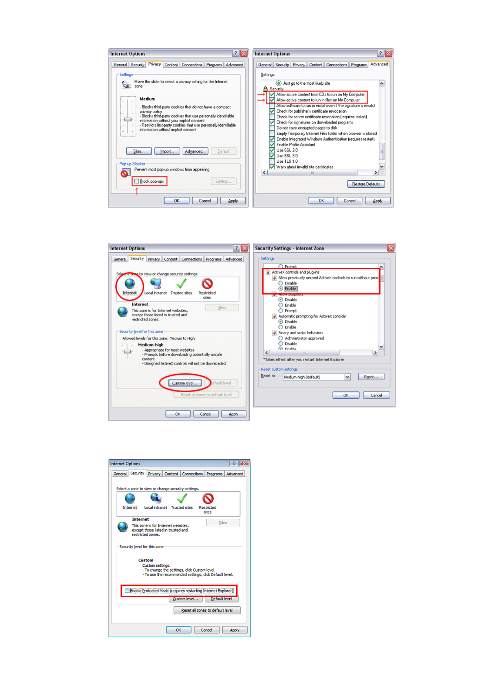
When Windows XP SP2 or Windows Vista is used, ActiveX control and popthe enhanced security function and this system may not work. In that case, perform the Internet Explorer
setting using the following procedure to restore normal operation.
1. Windows version check
[My Computer (right-click)] - [Properties]
2. Internet Explorer setting
[Tools] - [Internet Options]
Page 4
for Internet Explorer 7
for Windows Vista
Page 5

Operating Environment
PC : Pentium III or higher recommended
Monitor : 1024 x 768 or higher resolution recommended
Mouse : A mouse with wheel recommended
OS : Microsoft Windows 2000 SP4 / XP / Vista
Browser : Microsoft Internet Explorer 6.0 / 7.0
Drawing viewer : Autodesk DWF Viewer 6.0 / 7.0
* Use the software following respective license terms and conditions.
Functions Provided on Each Drawing Page
Parts Information Reference Function
When the character string of a part on the drawing is clicked, its information is popped up at the location.
You can get any parts information immediately on the screen without referring to the maintenance parts list.
Parts Search Function
You can search any part within the displayed drawing or within the whole schematic diagram/board view by
specifying a location number. The pop-up window displayed by clicking a part 's character string allows to
search the part within the applicable schematic diagram, board view or spare parts list.
A circle appears when the part is found, showing the part's location within the drawing.
Signal Line/Connector Destination Display Function
When a name at the end of a signal line in a divided schematic diagram is clicked, the destination of the
signal is searched and the display changes to the destination. Connecter destinations can also be searched in
the same way.
When two or more search results are provided, their drawing names are displayed, allowing you to choose a
desired drawing to display.
Layer Display Changing Function
When any of the color buttons on the toolbar is clicked, it can be selected to display desired layer in its color
or not to display each layer. This allows you to see the pattern layer only by setting other layers to "nondisplay".
PC Board View Pattern Highlighting Function
When a pattern on a board view is clicked, it is highlighted in green. This allows easy pattern tracing.
Specified Area Printing Function
The Autodesk DWF Viewer enables to print the displayed drawing region as it is on a printer. It also allows
to print a large-sized drawing in multiple pieces (tile printing).
Using with Network
PRECAUTION
To use ZEUS Service Manual Ver.2 with network, the file-path names written on the source files of each
Page 6
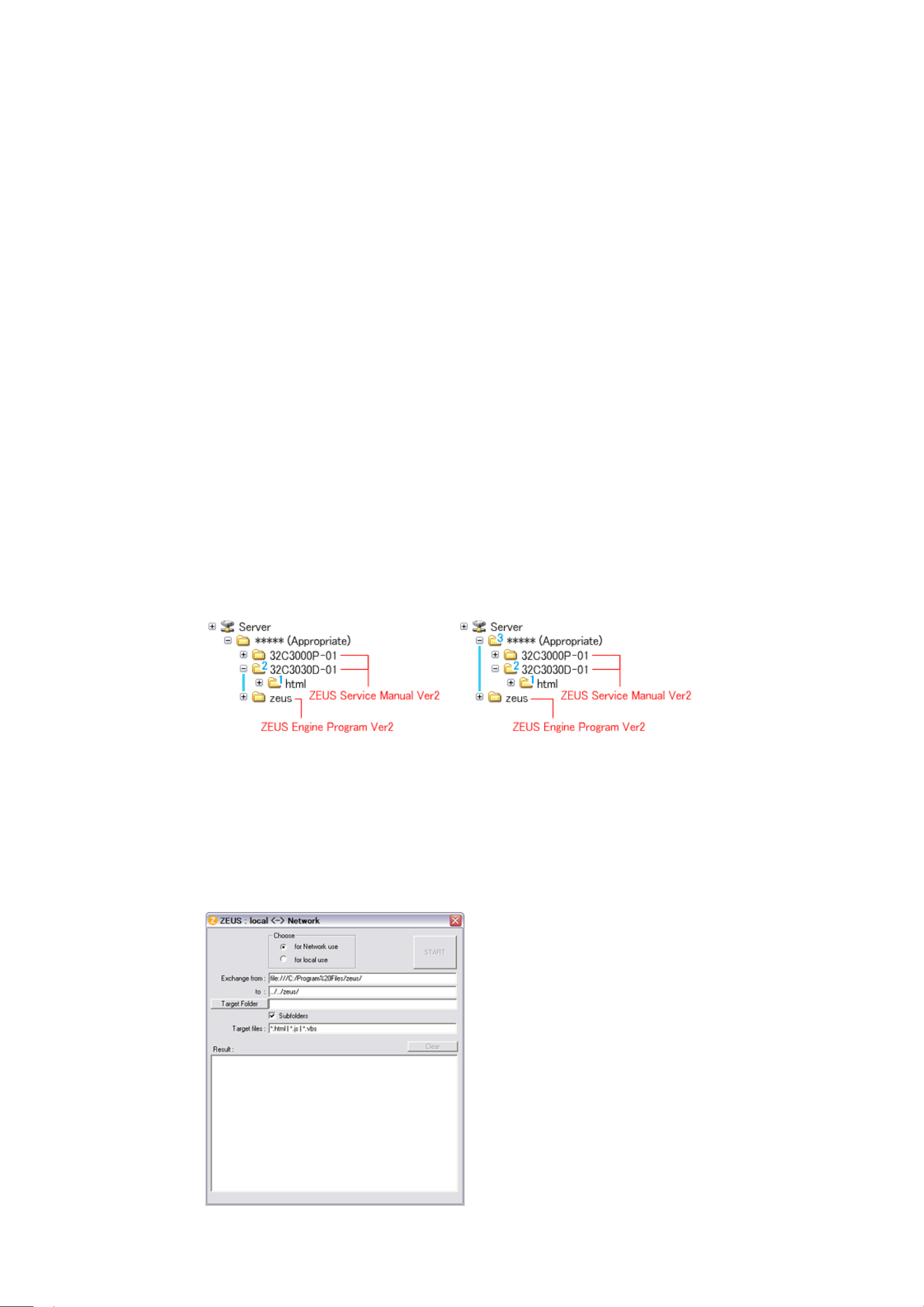
ZEUS Engine Program Ver.2 and ZEUS Service Manual Ver.2 are to be modified.
Perform the procedure described below.
Preparation
1. Run the program file zuesFPch.exe to install the program file for File-Path to the Local PC.
-> Download zeusFPch_setup.zip (2.3MB)
2. Run the program file ZeusSetup_v2.0.exe to install the ZEUS Engine Program in C:\Program
Files\zeus of the local PC. This can be done by running the installer program provided.
3. Create the appropriate folder where the ZEUS Engine Program Ver.2 and the ZEUS Service Manual
Ver.2 to be stored in the server.
4. Move the ZEUS Engine Program of step 2 to the folder created at step 3 in the Server.
5. Detach the ZEUS Service Manual Ver.2 to the folder created at step 3 in the Server.
6. Unzip the ZEUS Service Manual Ver.2 within the folder in the Server.
Example of folder
Procedure of File-Path
The zeusFPch is the exclusive program to exchange the file-path names written in both source files of ZEUS
Manual and ZEUS Engine program into those applicable to the network use.
Page 7
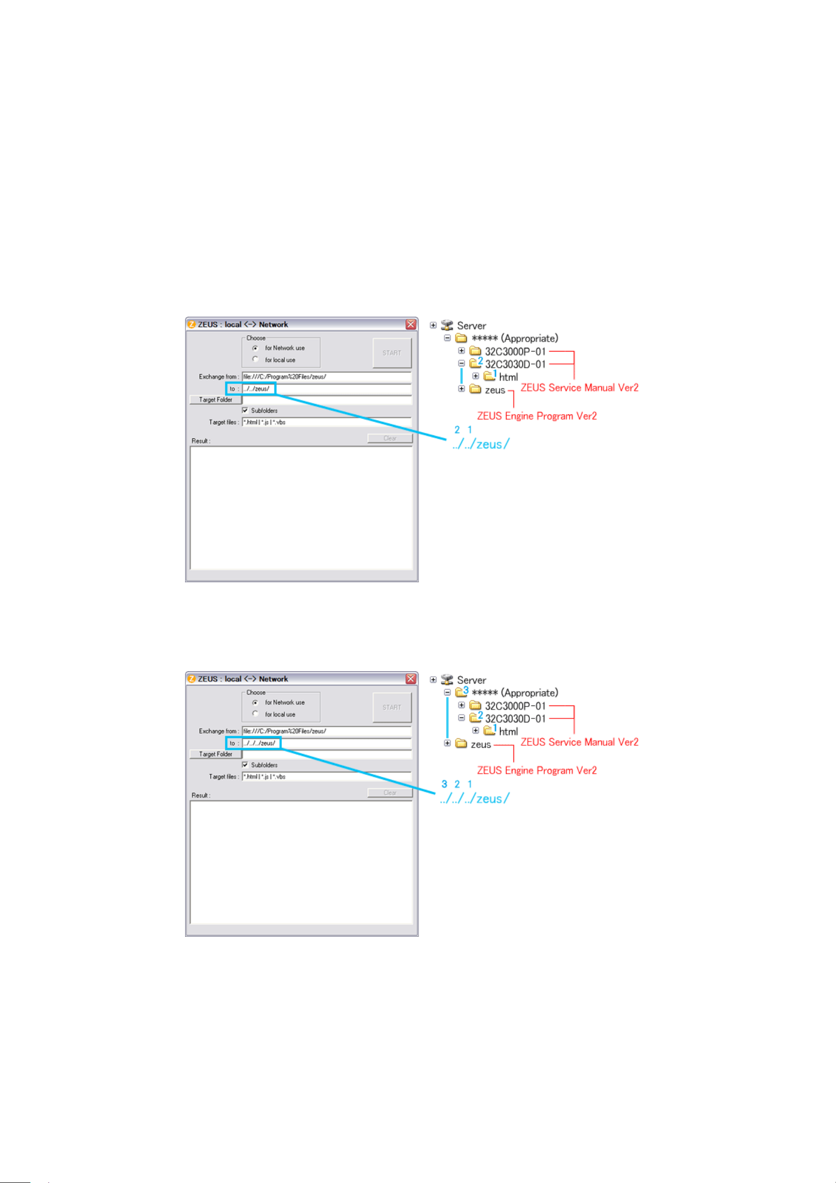
1. Whenever changing the file-
path of both ZEUS Engine Program and ZEUS Service Manual to use with
network, pay the attention to set the "Exchange to" column that should have a proper relation between
ZEUS Engine Program and ZEUS Service Manual with referring the following.
Run the zeusFPch and set "Exchange to" by referring to the examples below.
Example 1 :
In the "Exchange to" column shows the relation between ZEUS Service Manual and ZEUS Engine
Program.
../ counts the relation between.
Thus in this case, it must be ../../zeus/ (2 counts).
Example 2 :
In this case, it must be ../../../zeus/ (3 counts).
2. Run the zeusFPch to change the path in the ZEUS Engine Program Ver.2.
3. Set ZEUS Engine Program in the created folder in the server to the "Target Folder", and then press
"START".
(This procedure is one time only)
Page 8
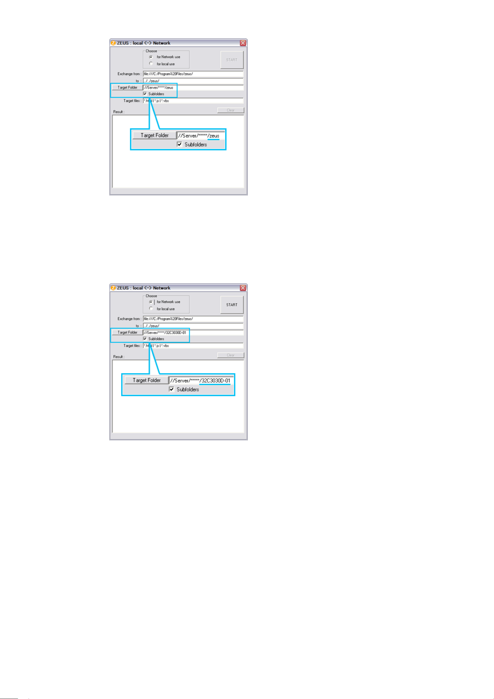
4. Run the ZeusFPch to change the path in the ZEUS Service Manual Ver2.
5. Set unzipped ZEUS Service Manual in the created folder in the server to the "Target Folder", and then
press "START".
(This procedure is required whenever placing service manual.)
Confirmation
Confirm that service manual on the server can be operated normally by client PC.
Note:
In case of accessing the ZEUS Manual through WEB site, the small pop-up window appears at the left
bottom corner on the screen whenever searching the location links. This is not malfunction.
Page 9
IMPORTANT NOTICE
Through WEB, ver. 6.5 has been released but with it, the linking function in this manual may
A Known Malfunction
Autodesk® DWF™ Viewer version
(Free software provided through WEB)
Use Autodesk DWF Viewer ver. 6.0.
not work properly.
If ver. 6.5 has been installed, uninstall it and reinstall ver. 6.0.
To get ver. 6.0, click the icon, or contact to the nearest Toshiba Service Centre for further
assistance.
Freezing windows opened
(Cannot close the open windows)
This may happen occasionally.
In case of encountering this, follow the procedure below.
1. Press [Ctrl], [Alt] and [Delete] keys at the same time to engage windows security
windows.
2. Then, choose TASK manager and Application tab, and select TOSHIBA SERVICE
MANUAL-Microsoft Internet Explorer.
3. Click TASK-end.
Main Window back forwarded
The real cause has not been found yet but with this condition, nothing disturbs the service
manual operation.
Continue to use by operating the windows.
Precaution when opening the diagrams
While opening the diagrams, the menu in the left frame changes its color to GRAY. This is
an indication that the viewer is processing.
With this condition, the menu indication color may stick to the GRAY color or Windows
may freeze if clicking other menu.
To avoid such things, do not operate any others while menu turns GRAY color.
If entering this, re-open the service manual or refresh the left frame.
Page 10

GREEN PRODUCT PROCUREMENT
Corporation recognizes environmental protection as a key management tasks, and is doing its
The EC is actively promoting the WEEE & RoHS Directives that define standards for
recycling and reuse of Waste Electrical and Electronic Equipment and for the Restriction of
the use of certain Hazardous Substances. From July 1, 2006, the RoHS Directive will
prohibit any marketing of new products containing the restricted substances.
Increasing attention is given to issues related to the global environmental. Toshiba
utmost to enhance and improve the quality and scope of its environmental activities. In line
with this, Toshiba proactively promotes Green Procurement, and seeks to purchase and use
products, parts and materials that have low environmental impacts.
Green procurement of parts is not only confined to manufacture. The same green parts used
in manufacture must also be used as replacement parts.
Page 11

LEAD-FREE SOLDER
free solder must
free solder may result in damage to the component and or PCB being
This product is manufactured using lead-free solder as a part of a movement within the
consumer products industry at large to be environmentally responsible. Leadbe used in the servicing and repair of this product.
WARNING: This product is manufactured using lead free solder.
DO NOT USE LEAD BASED SOLDER TO REPAIR THIS PRODUCT!
The melting temperature of lead-free solder is higher than that of leaded solder by 86ºF to
104ºF (30ºC to 40ºC). Use of a soldering iron designed for lead-based solders to repair
product made with leadsoldered. Great care should be made to ensure high-quality soldering when servicing this
product especially when soldering large components, through-hole pins, and on PCBs as the
level of heat required to melt lead-free solder is high.
Page 12
SAFETY INSTRUCTION
Always keep tools, components of the product, etc away from the children, These items
NEVER remodel the product in any way. Remodeling can result in improper operation,
WARNING: BEFORE SERVICING THIS CHASSIS, READ THE "SAFETY
PRECAUTION" AND "PRODUCT SAFETY NOTICE" INSTRUCTIONS BELOW.
Safety Precaution
WARNING: SERVICING SHOULD NOT BE ATTEMPTED BY ANYONE
UNFAMILIAR WITH THE NECESSARY PRECAUTIONS ON THIS RECEIVER.
THE FOLLOWING ARE THE NECESSARY PRECAUTIONS TO BE OBSERVED
BEFORE SERVICING THIS CHASSIS.
1. An isolation transformer should be connected in the power line between the receiver
and the AC line before any service is performed on the receiver.
2. Always disconnect the power plug before any disassembling of the product. It may
result in electrical shock.
3. When replacing a chassis in the cabinet, always be certain that all the protective
devices are put back in place, such as nonmetallic control knobs, insulating covers,
shields, isolation resistor-capacitor network, etc.
4.
may cause injury to children.
5. Depending on the model, use an isolation transformer or wear suitable gloves when
servicing with the power on, and disconnect the power plug to avoid electrical shock
when replacing parts. In some cases, alternating current is also impressed in the
chassis, so electrical shock is possible if the chassis is contacted with the power on.
6. Always use the replacement parts specified for the particular model when making
repairs. The parts used in products require special safety characteristics such as
inflammability, voltage resistance, etc. therefore, use only replacement parts that have
these same characteristics. Use only the specified parts when the mark is indicated
in the circuit diagram or parts list.
7. Parts mounting and routing dressing of wirings should be the same as that used
originally. For safety purposes, insulating materials such as isolation tube or tape are
sometimes used and printed circuit boards are sometimes mounted floating. Also make
sure that wirings is routed and clamped to avoid parts that generate heat and which use
high voltage. Always follow the manufactured wiring routes / dressings.
8. Always ensure that all internal wirings are in accordance before re-assembling the
external casing after a repairing completed. Do not allow internal wiring to be pinched
by cabinets, panels, etc. Any error in reassembly or wiring can result in electrical
leakage, flame, etc., and may be hazardous.
9.
malfunction, or electrical leakage and flame, which may be hazardous.
Page 13
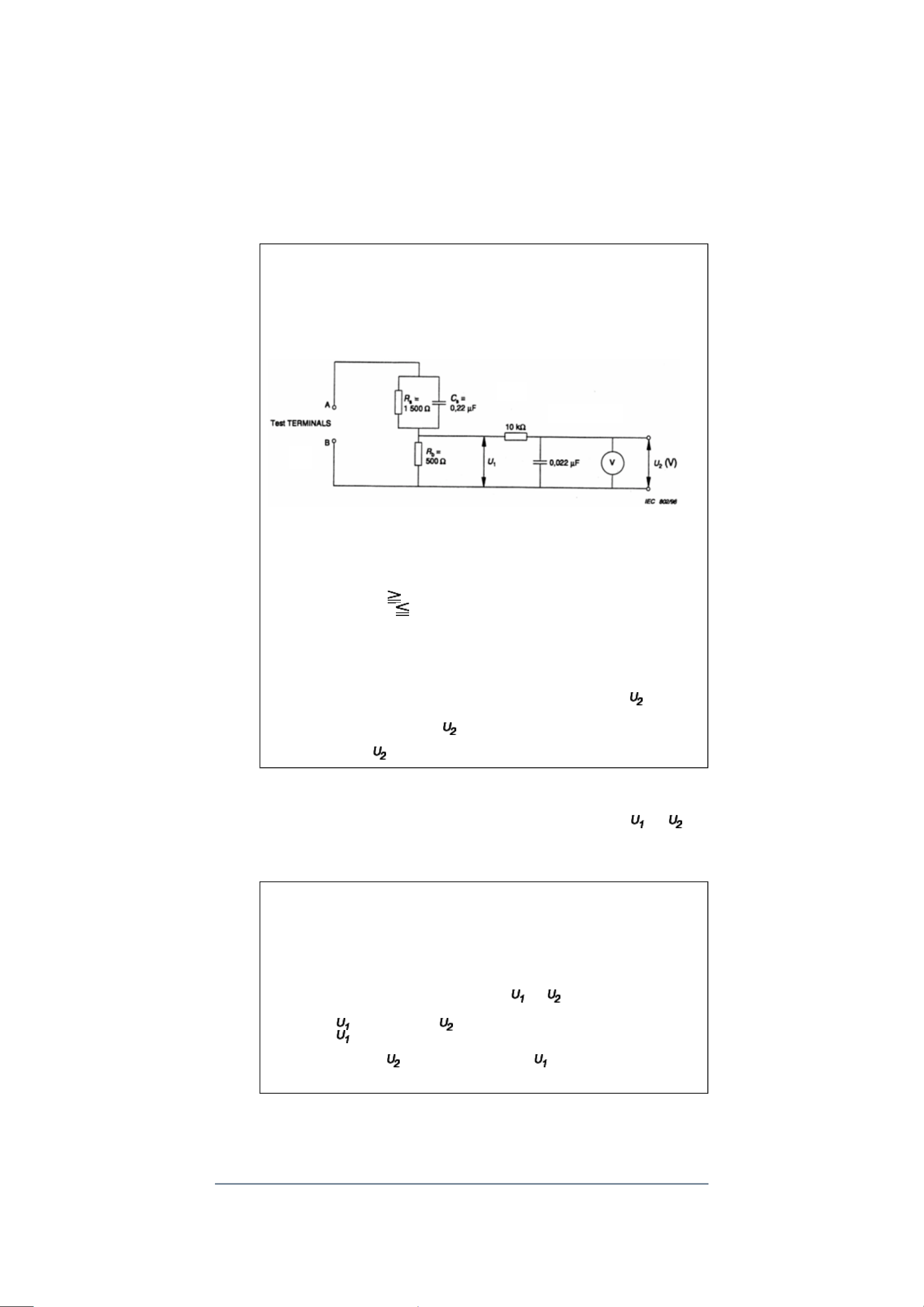
10. Touch current check. (After completing the work, measure touch current to prevent an
V: Voltmeter or oscilloscope
electric shock.)
Plug the AC cord directly into the AC outlet. Do NOT use an isolation transformer
for this check.
Connect a measuring network for touch currents between each exposed metallic part
on the set and a good earth ground such as a water pipe.
Annex D
(normative)
Measuring network for TOUCH CURRENTS
Resistance values in orms (Ω).
(r.m.s. or peak reading)
Input resistance : 1 MΩ
Input capacitance : 200 pF
Frequency range : 15 Hz to 1 MHz and d.c. respectively
Note: Appropriate measures should be taken to obtain the correct value in case of non
sinusoidal waveforms.
The measuring instrument is calibrated by comparing the frequency factor of with the
solid line in figure F.2 of IEC 60990 at various frequencies. A calibration curve is
constructed showing the deviation of from the ideal curve as a function of frequency.
TOUCH CURRENT = /500 (peak value).
The potential at any point (TOUCH CURRENT) expressed as voltage and
does not exceed the following value:
The part or contact of a TERMINAL is not HAZARDOUS LIVE if:
a) The open-circuit voltage should not exceed 35 V (peak) a.c. or 60 V d.c. or, if a) is not
met.
b) The measurement of the TOUCH CURRENT shall be carried out in accordance with
IEC 60990, with the measuring network described in Annex D of this standard.
The TOUCH CURRENT expressed as voltages and , does not exceed the
following values:
- for a.c. : = 35 V (peak) and = 0.35 V (peak);
- for d.c. : = 1.0 V
Note: The limit values of = 0.35 V (peak) for a.c. and = 1.0 V for d.c. correspond to
the values 0.7 mA (peak) a.c. and 2.0 mA d.c.
Product Safety Notice
Many electrical and mechanical parts in this chassis have special safety-related
Page 14

characteristics. These characteristics are often passed unnoticed by a visual inspection and
the protection afforded by them cannot necessarily be obtained by using replacement
components rated for higher voltage, wattage, etc. Replacement parts which have these
special safety characteristics are identified in this manual and its supplements; electrical
components having such features are identified by the international hazard symbols on the
schematic diagram and the parts list.
Before replacing any of these components, read the parts list in this manual carefully. The
use of substitute replacement parts which do not have the same safety characteristics as
specified in the parts list may create electrical shock, fire, or other hazards.
Page 15
SAFETY INSTRUCTION
should enter the mouth, rinse the mouth thoroughly with water. If the fluid should contact the
When attaching the LCD module to the LCD cover, position it appropriately and fasten
Handling the LCD Module
Safety Precaution
In the event that the screen is damaged or the liquid crystal (fluid) leaks, do not breathe in or
drink this fluid.
Also, never touch this fluid. Such actions could cause toxicity or skin irritation. If this fluid
skin or clothing, wipe off with alcohol, etc., and rinse thoroughly with water. If the fluid
should enter the eyes, immediately rinse the eyes thoroughly with running water.
Precautions for Handling the LCD Module
CAUTION: The metal edges of the LCD module are sharp, handle it with
care.
The LCD module can easily be damaged during disassembly or reassembly; therefore,
always observe the following precautions when handling the module.
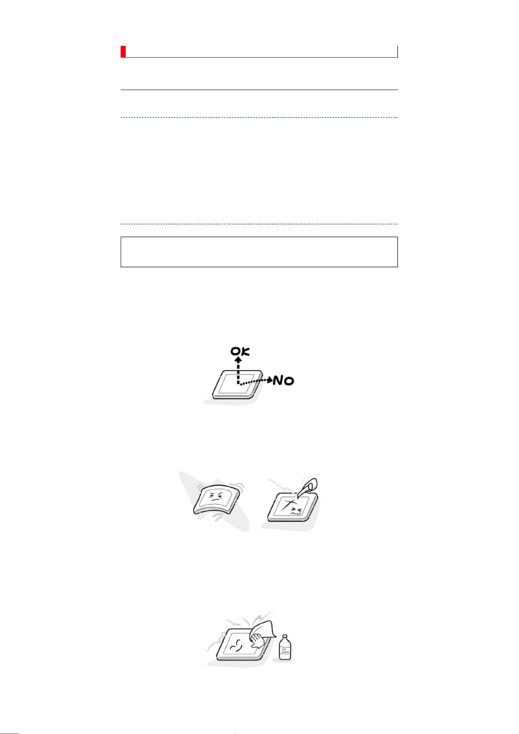
1.
at the position where the display can be viewed most conveniently.
2. Carefully align the holes at all four corners of the LCD module with the corresponding
holes in the LCD cover and fasten with screws. Do not strongly push on the module
because any impact can adversely affect the performance. Also use caution when
handling the polarized screen because it can easily be damaged.
3. If the panel surface becomes soiled, wipe with cotton or a soft cloth. If this does not
remove the soiling, breathe on the surface and then wipe again.
If the panel surface is extremely solied, use a CRT cleaner as a cleaner. Wipe off the
panel surface by drop the cleaner on the cloth. Do not drop the cleaner on the panel.
Pay attention not to scratch the panel surface.
4. Leaving water or other fluids on the panel screen for an extended period of time can
Page 16
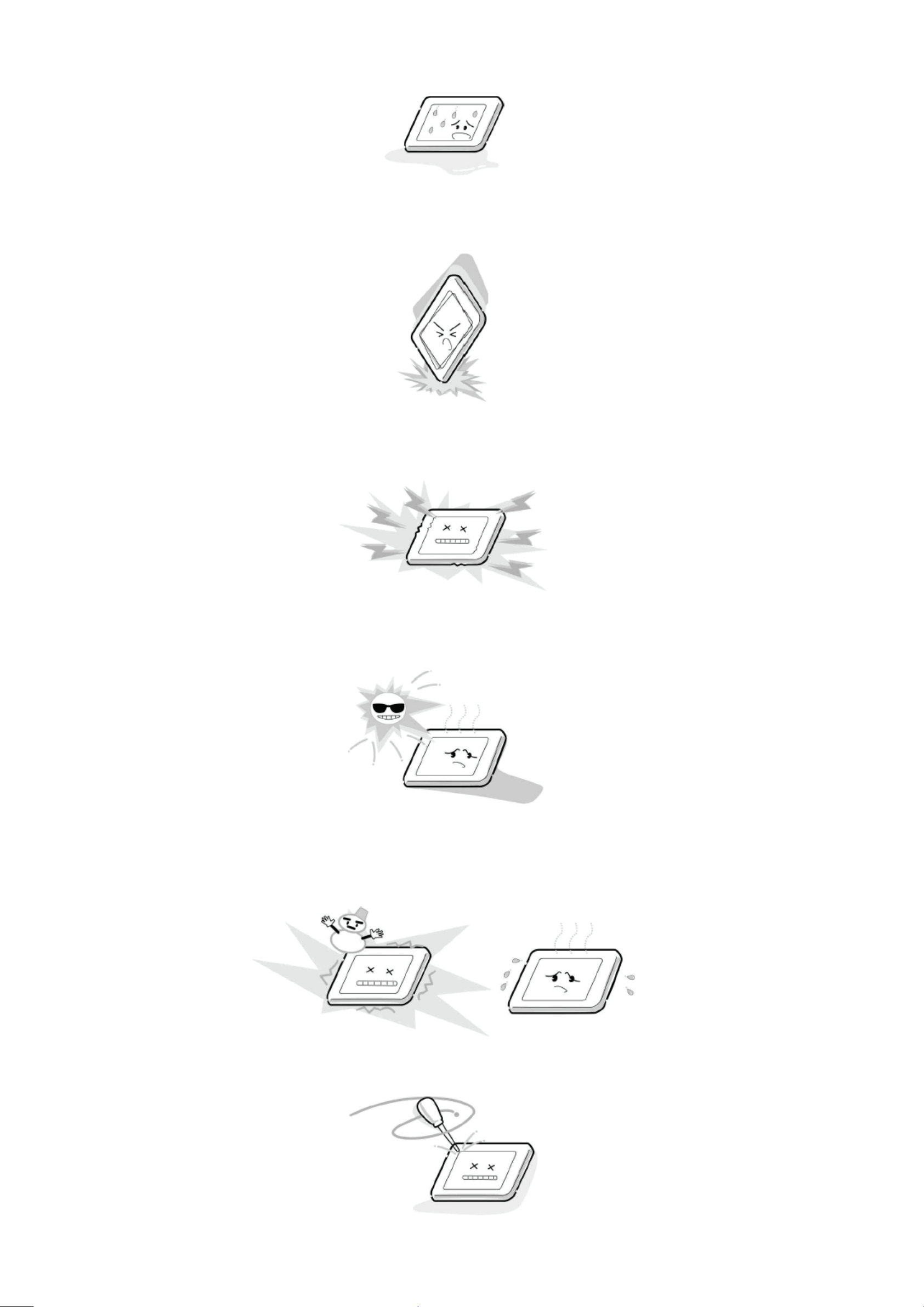
result in discoloration or stripes. Immediately remove any type of fluid from the screen.
5. Glass is used in the panel, so do not drop or strike with hard objects. Such actions can
damage the panel.
6. CMOS-LSI circuitry is used in the LCD module, so avoid damage due to static
electricity. When handling the module, use a wrist ground or anchor ground.
7. Do not expose the LCD module to direct sunlight or strong ultraviolet rays for an
extended period of time.
8. Do not store the LCD module below the temperature conditions described in the
specifications. Failure to do so could result in freezing of the liquid crystal due to cold
air or loss of resilience or other damage.
9. Do not disassemble the LCD module. Such actions could result in improper operation.
Page 17

10. When transporting the LCD module, do not use packing containing epoxy resin
(amine) or silicon resin (alcohol or oxim). The gas generated by these materials can
cause loss of polarity.
Page 18
U02A
KEY
U01A
MAIN
POWER
U03A
AC SW
U04A LED
U04B RMT
Page 19
Page 20
Page 21
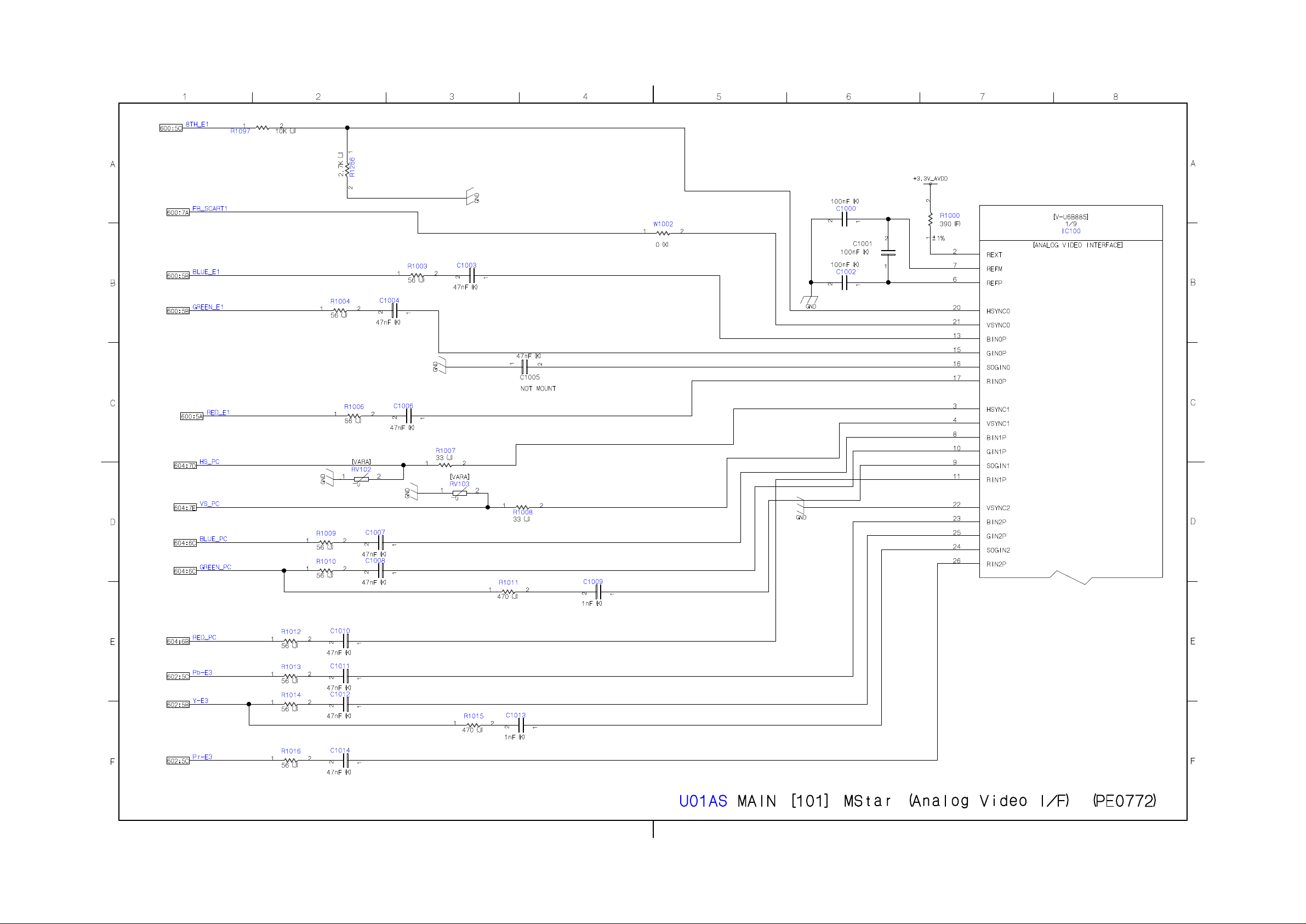
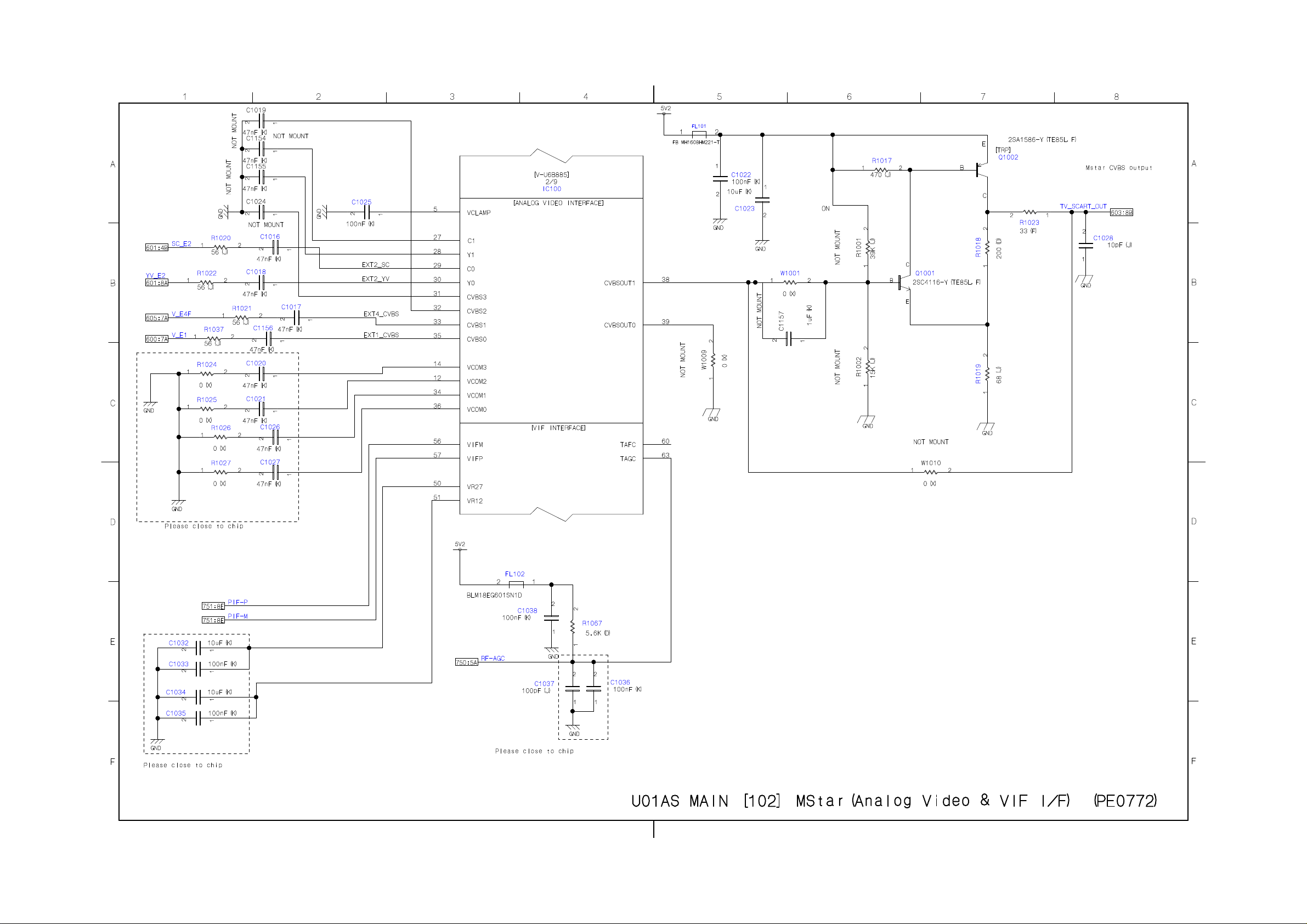
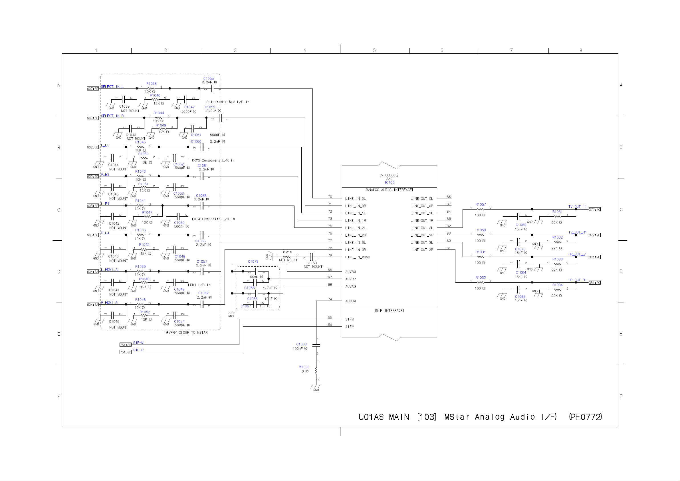
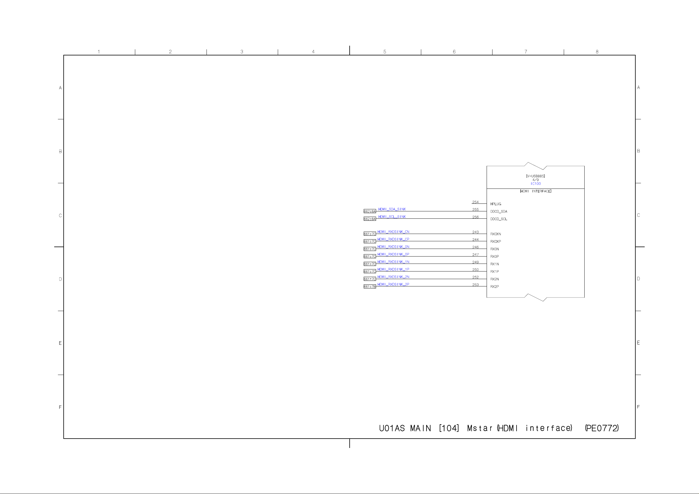
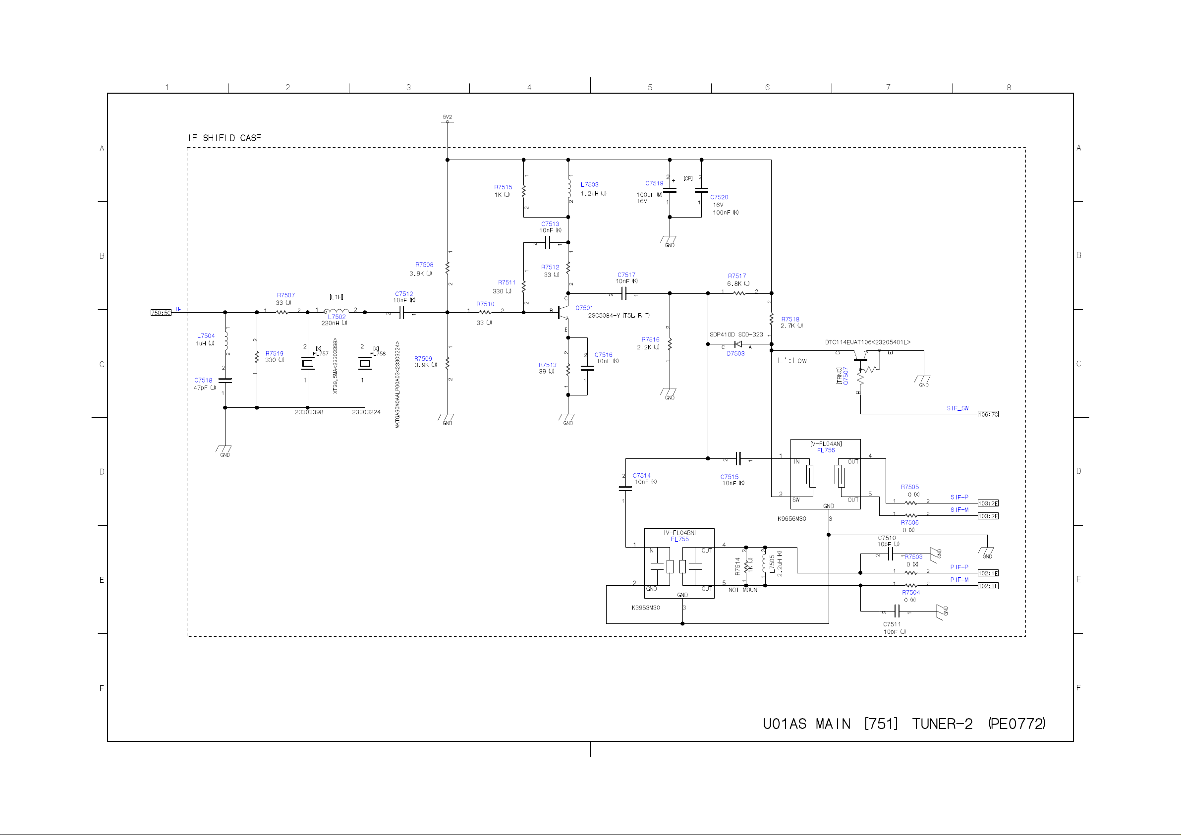
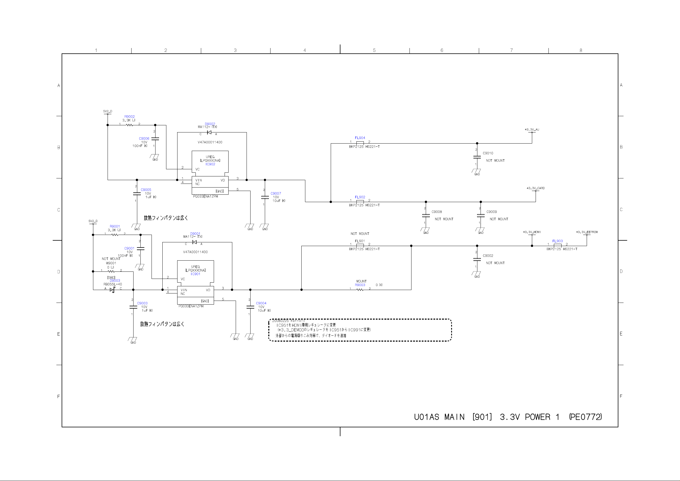
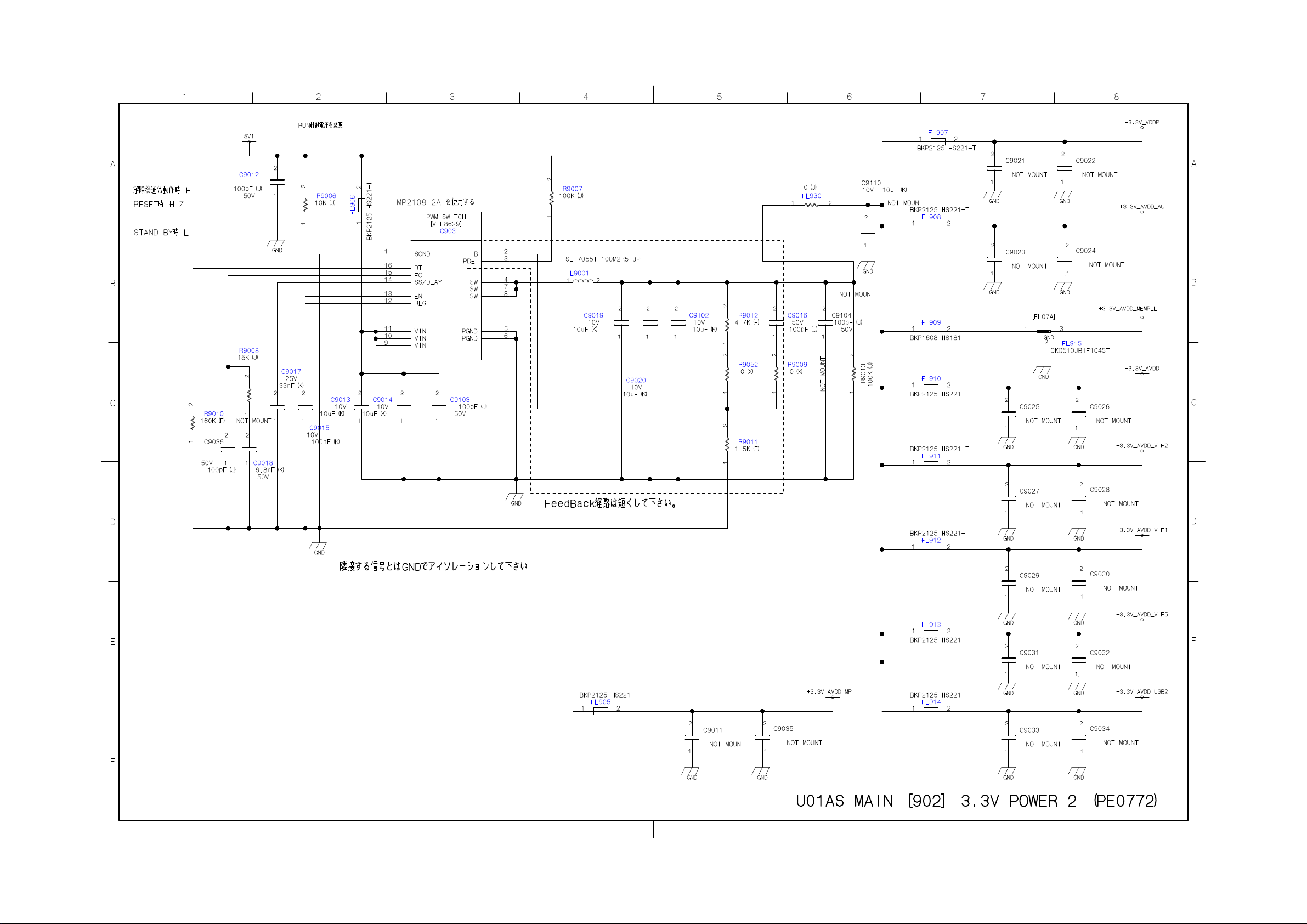
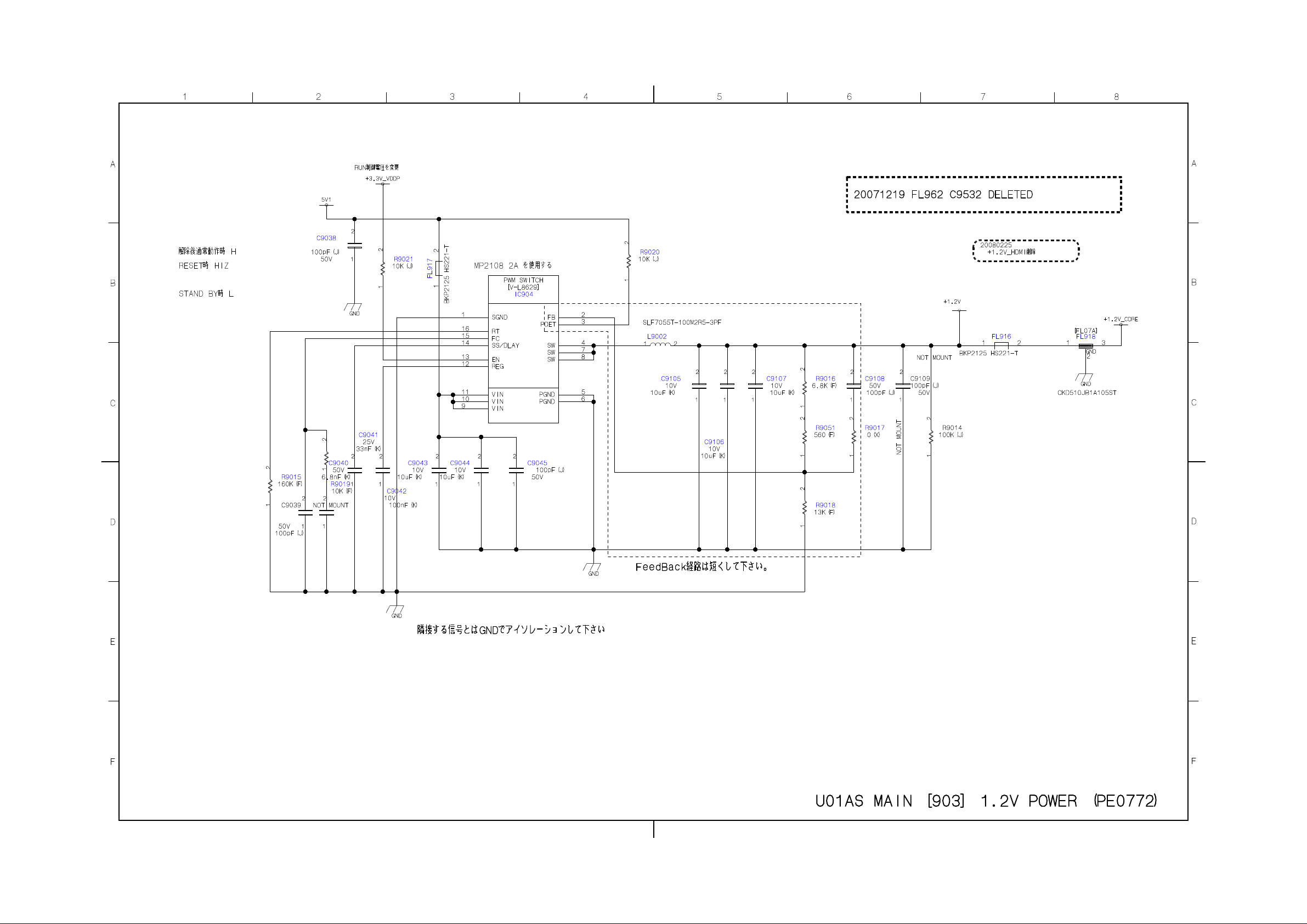
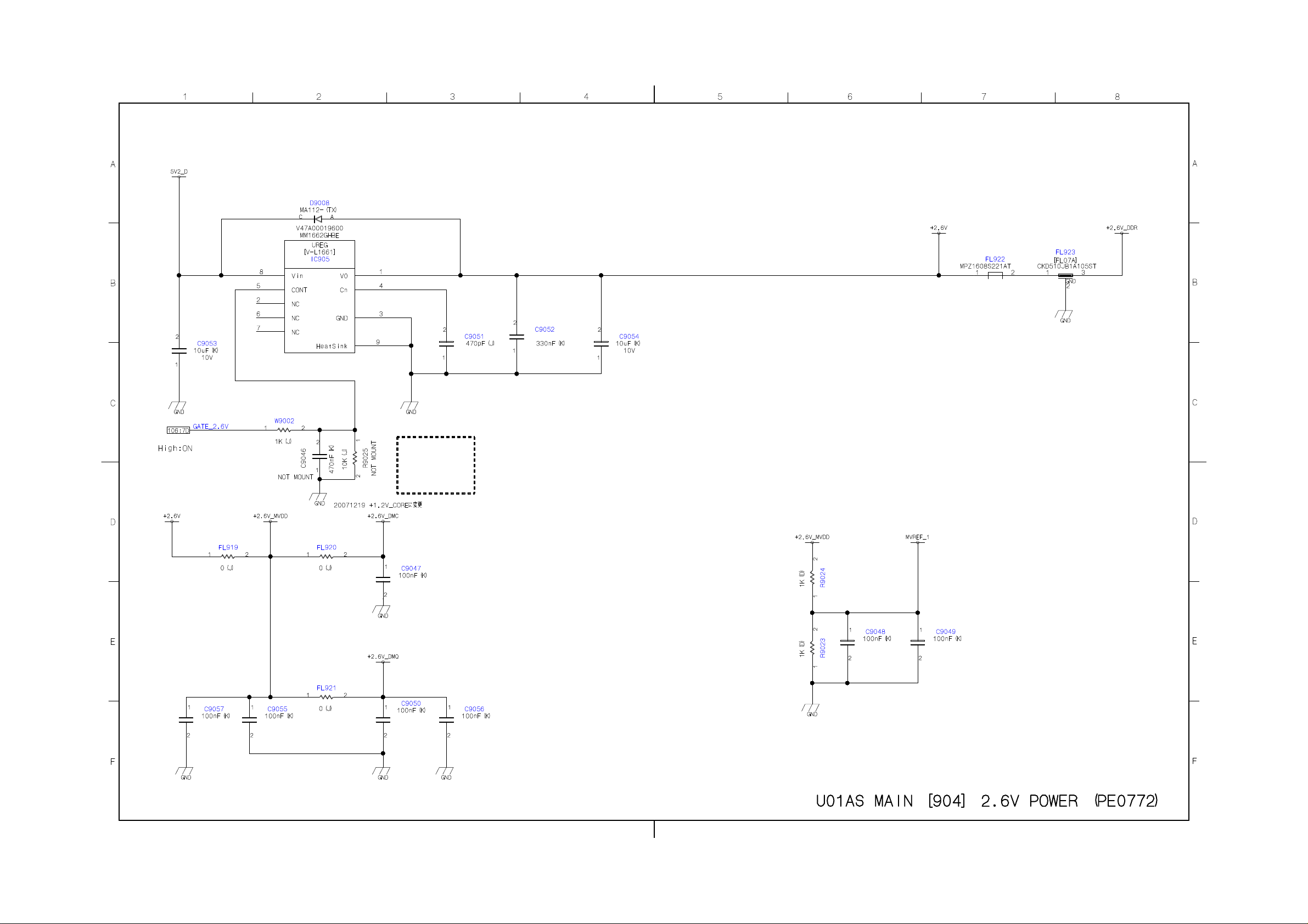
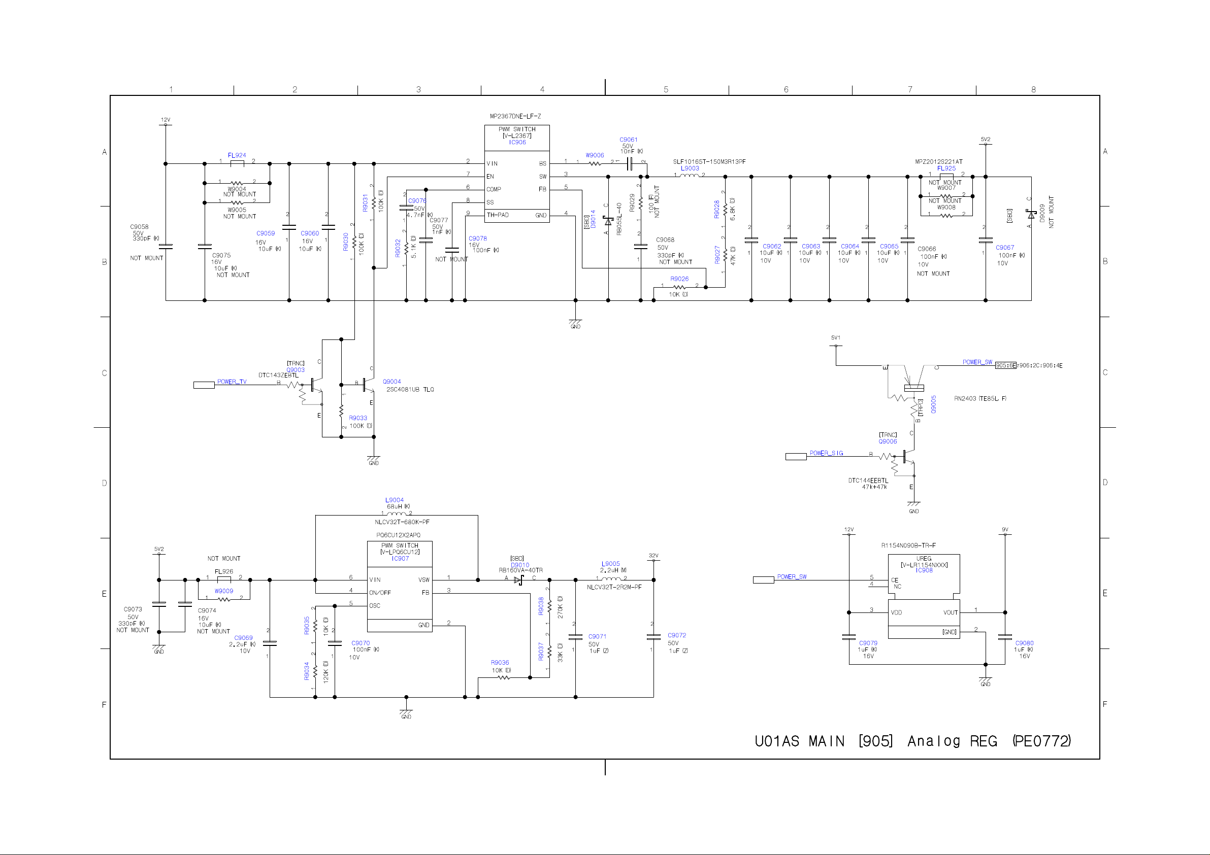
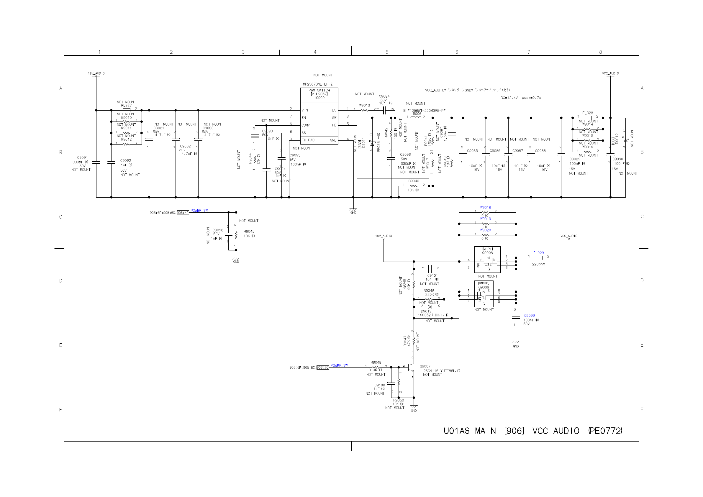
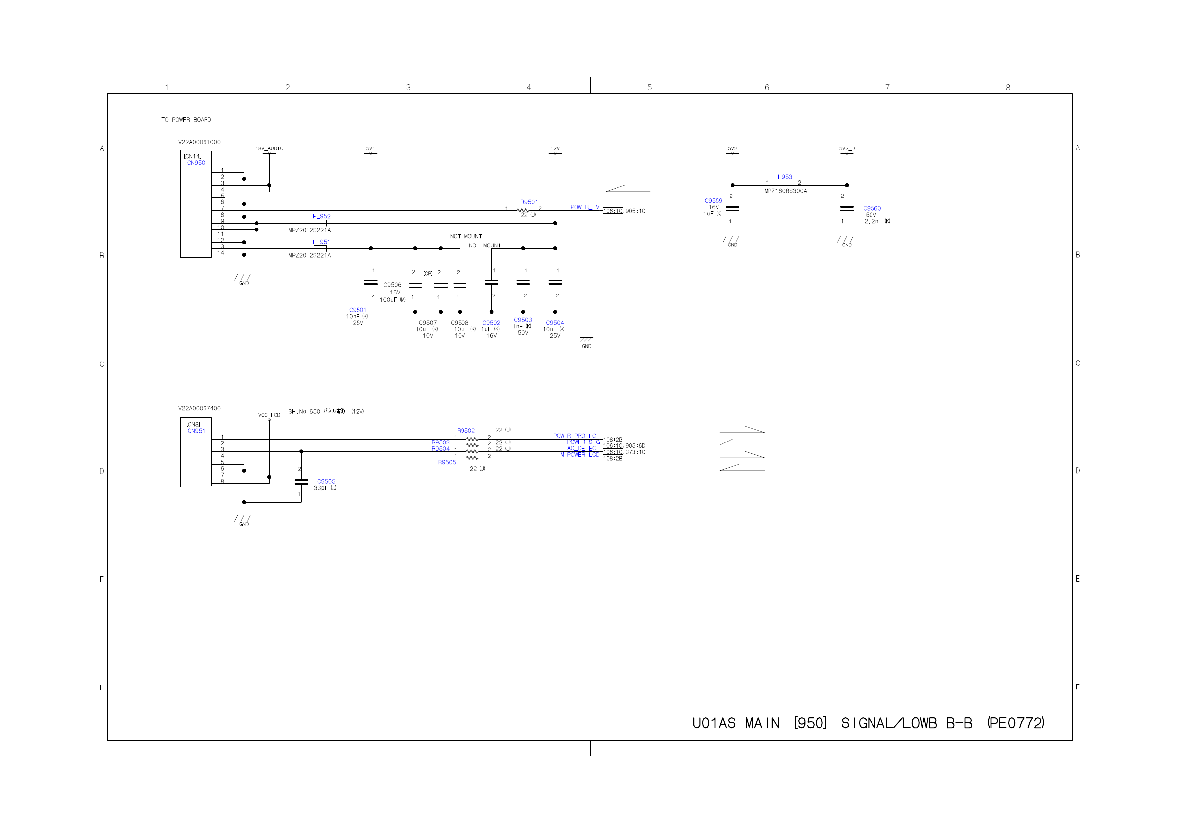
SCHEMATIC DIAGRAM
Precaution
WARNING: BEFORE SERVICING THIS CHASSIS, READ THE "X-RAY
RADIATION PRECAUTION" FOR DIRECT VIEW CTV ONLY, "SAFETY
PRECAUTION" AND "PRODUCT SAFETY NOTICE" OF THIS MANUAL.
CAUTION: The international hazard symbols " " in the schematic diagram
and the parts list designate components which have special characteristics
important for safety and should be replaced only with types identical to
those in the original circuit or specified in the parts list.
The mounting position of replacements is to be identical with originals.
Before replacing any of these components, read carefully the SAFETY
PRECAUTION and PRODUCT SAFETY NOTICE.
Do not degrade the safety of the receiver through improper servicing.
Note:
1. RESISTOR
Resistance is shown in ohm [K=1,000, M=1,000,000]. All resistors are 1/6 W and 5 %
tolerance carbon resistor, unless otherwise noted as the following marks.
1/2R : Metal or Metal oxide of 1/2 watt
1/2S : Carbon composition of 1/2 watt
1RF : Fuse resistor of 1 watt
10 W : Cement of 10 watt
K : ±10 %
G : ±2 %
F : ±1 %
2. CAPACITOR
Unless otherwise noted in schematic, all capacitor values less than 1 are expressed in
µF, and the values more than 1 in pF.
All capacitors are ceramic 50 V, unless otherwise noted as the following marks.
= Electrolytic capacitor
= Mylar capacitor
3. The parts indicated with " " have special characteristics, and should be replaced with
identical parts only.
4. Voltages read with DIGITAL MULTI-METER from point indicated to chassis ground,
using a color bar signal with all controls at normal, line voltage at nominal AC volts.
5. Waveforms are taken receiving color bar signal with enough sensitivity.
6. Voltage reading shown are nominal values and may vary ±20 % except H.V.
Page 22
Page 23
Page 24
Page 25
Page 26
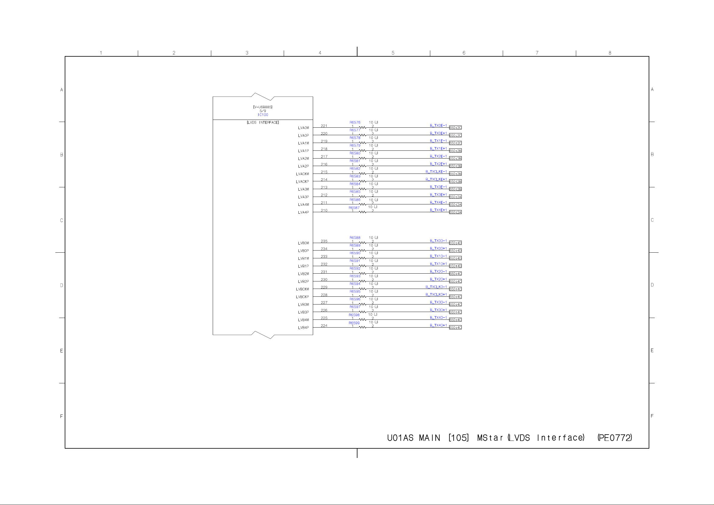
Page 27
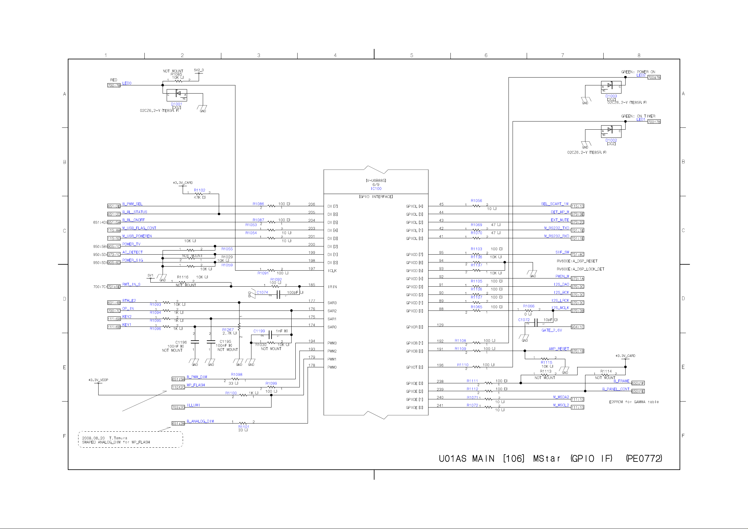
Page 28
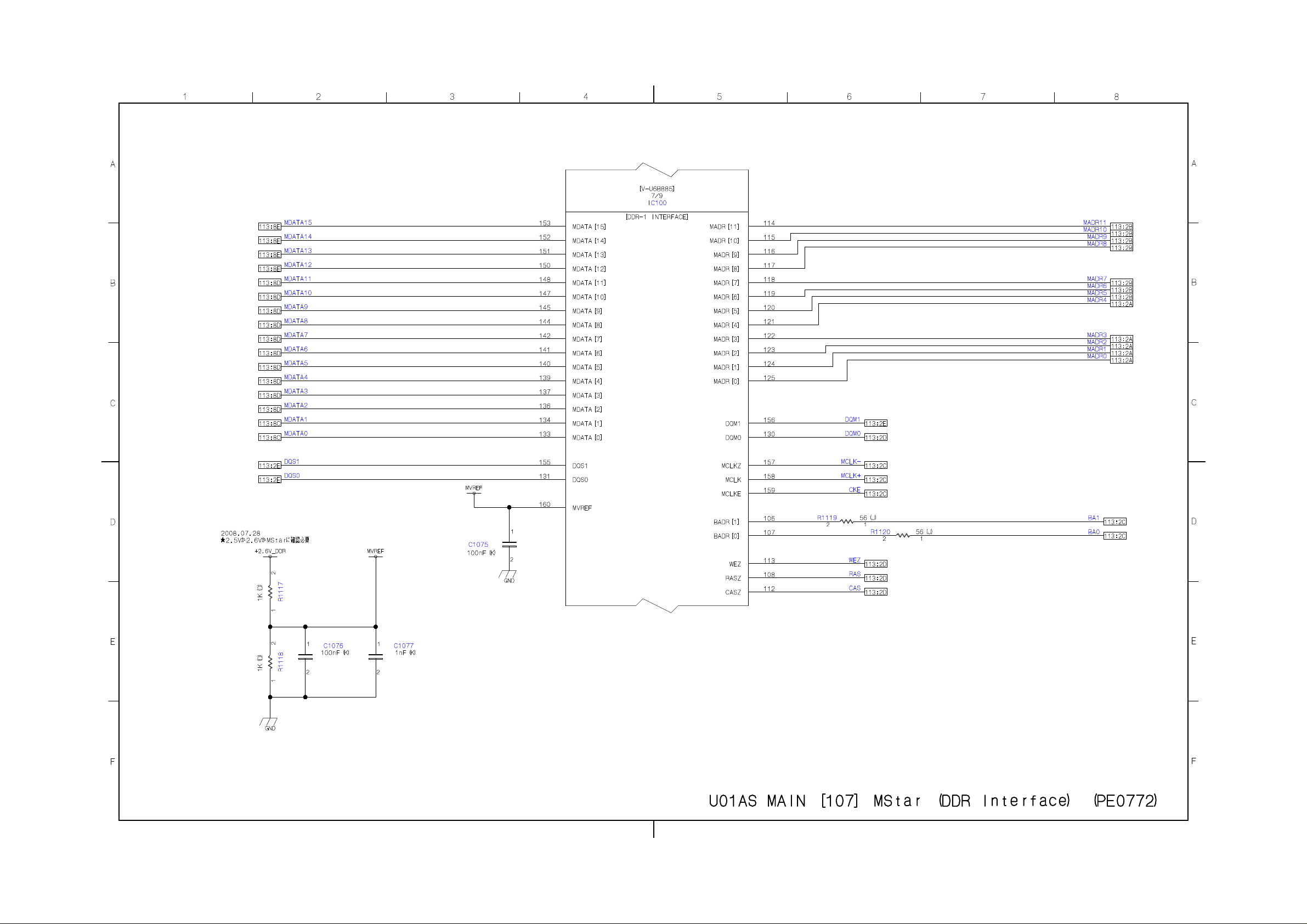
Page 29
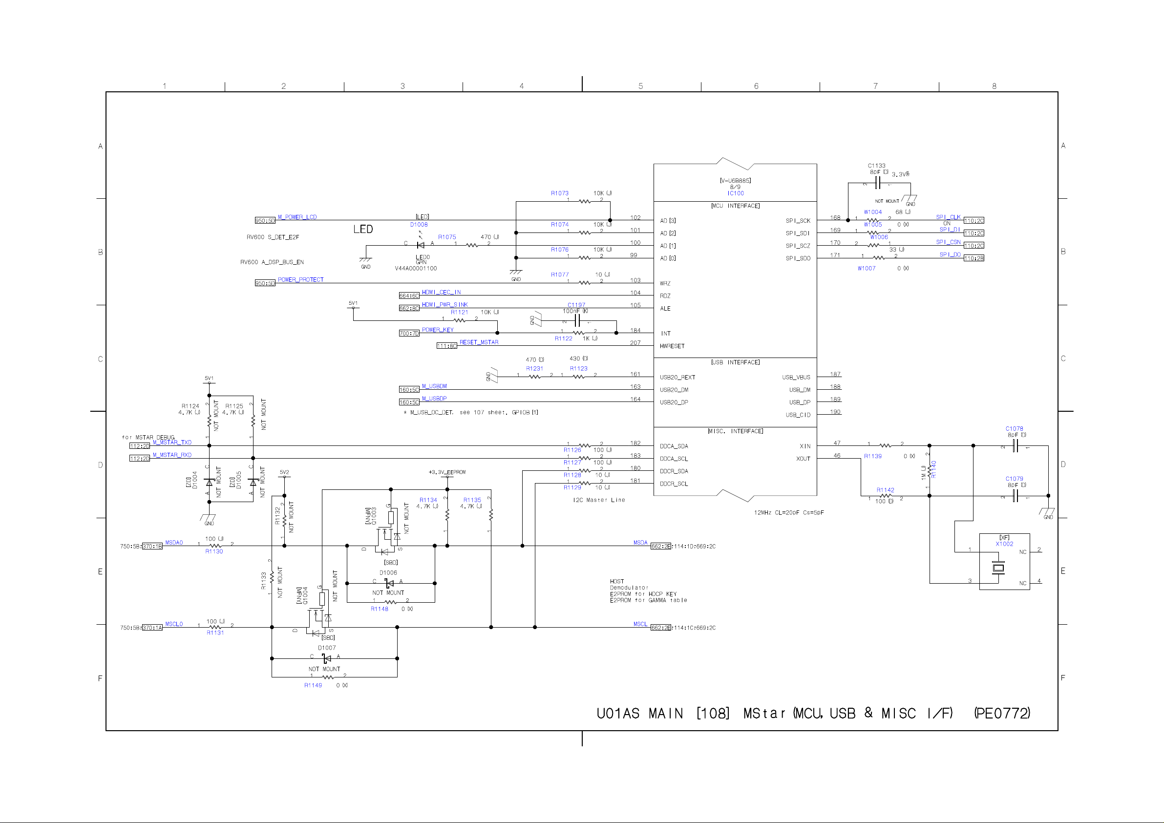
Page 30
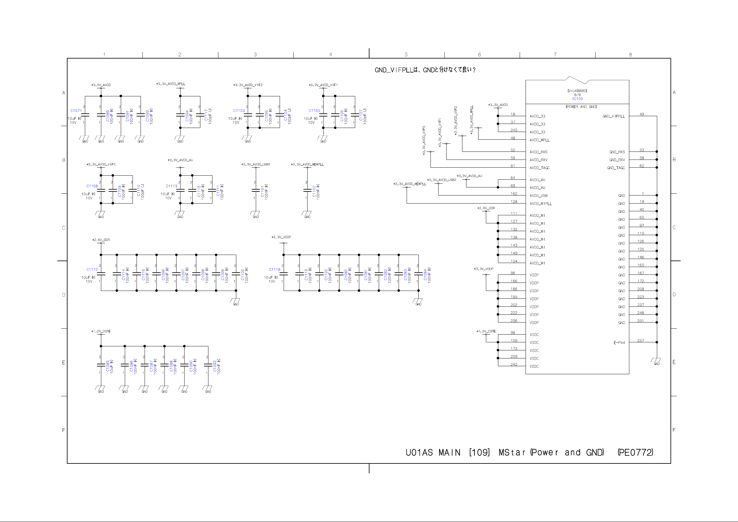
Page 31
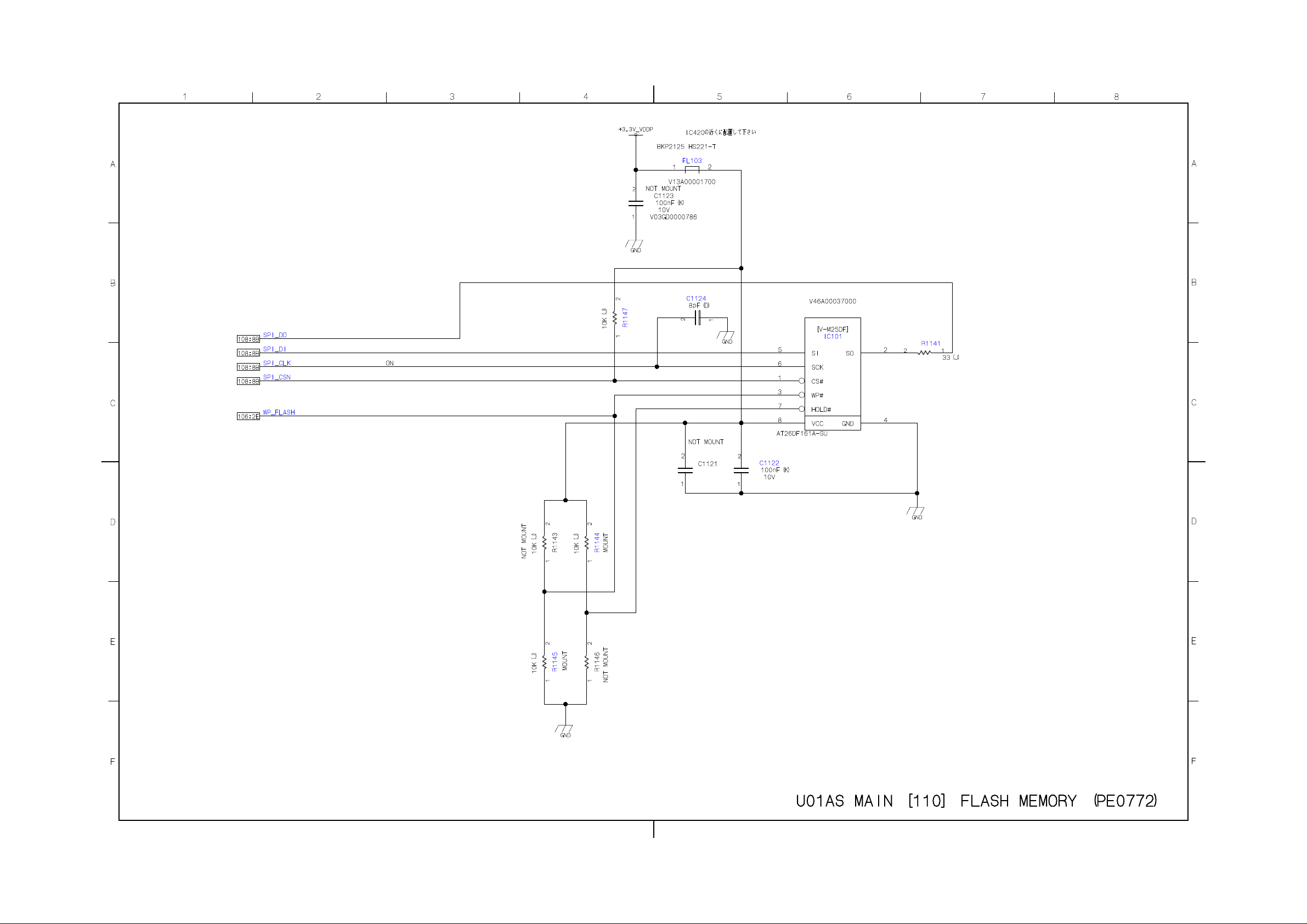
Page 32
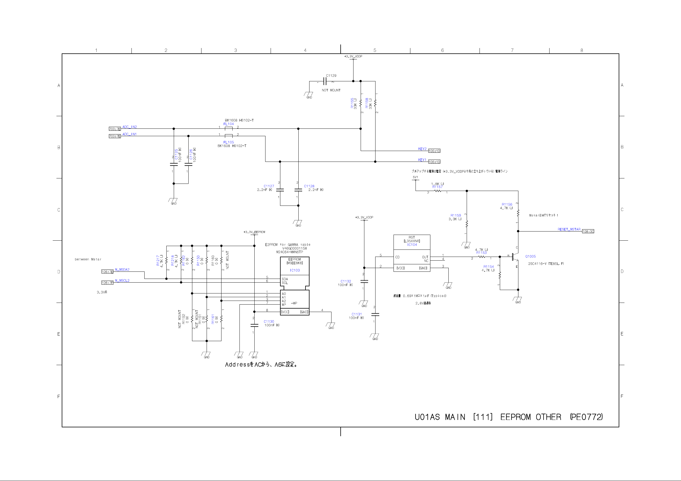
Page 33
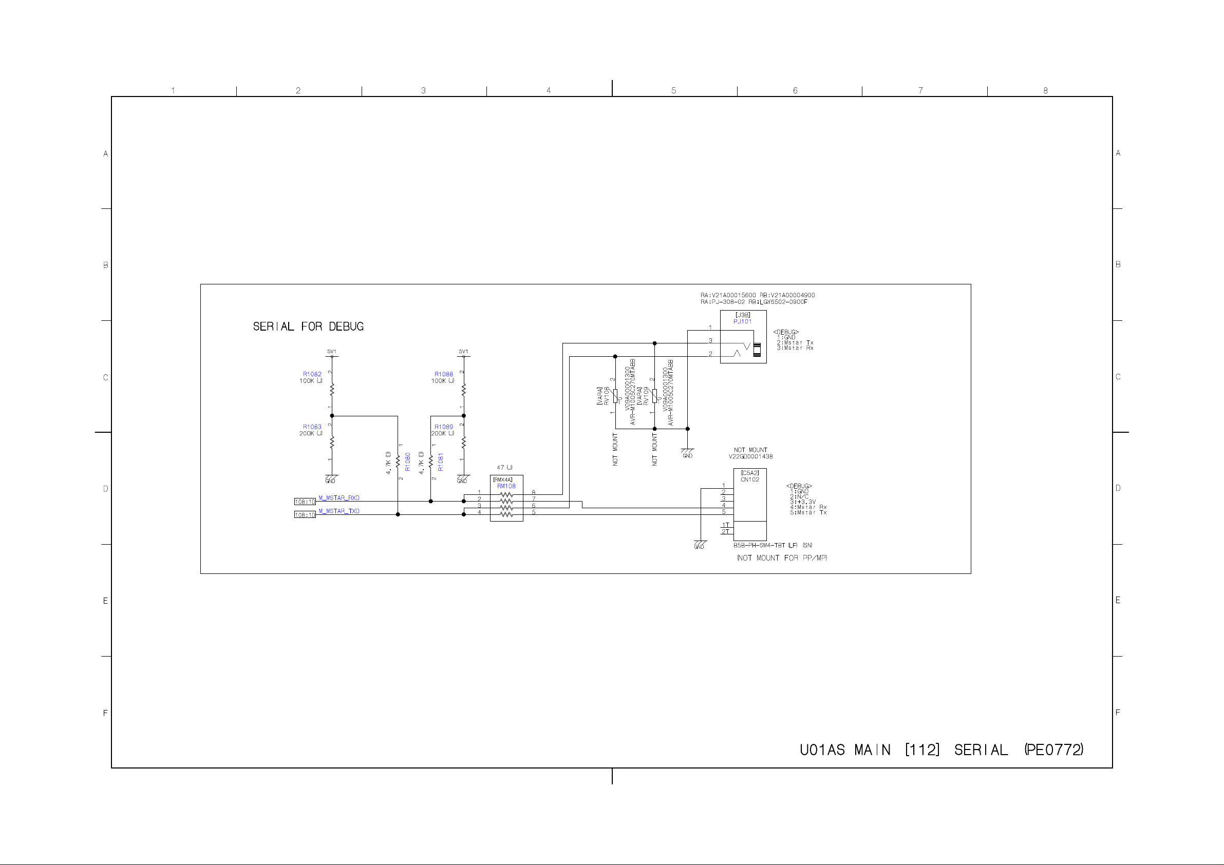
Page 34
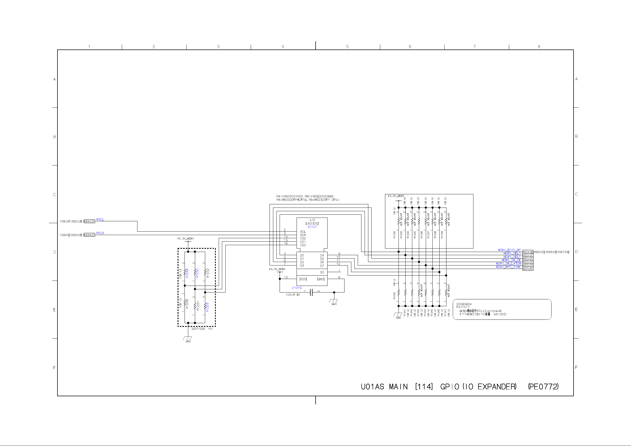
Page 35
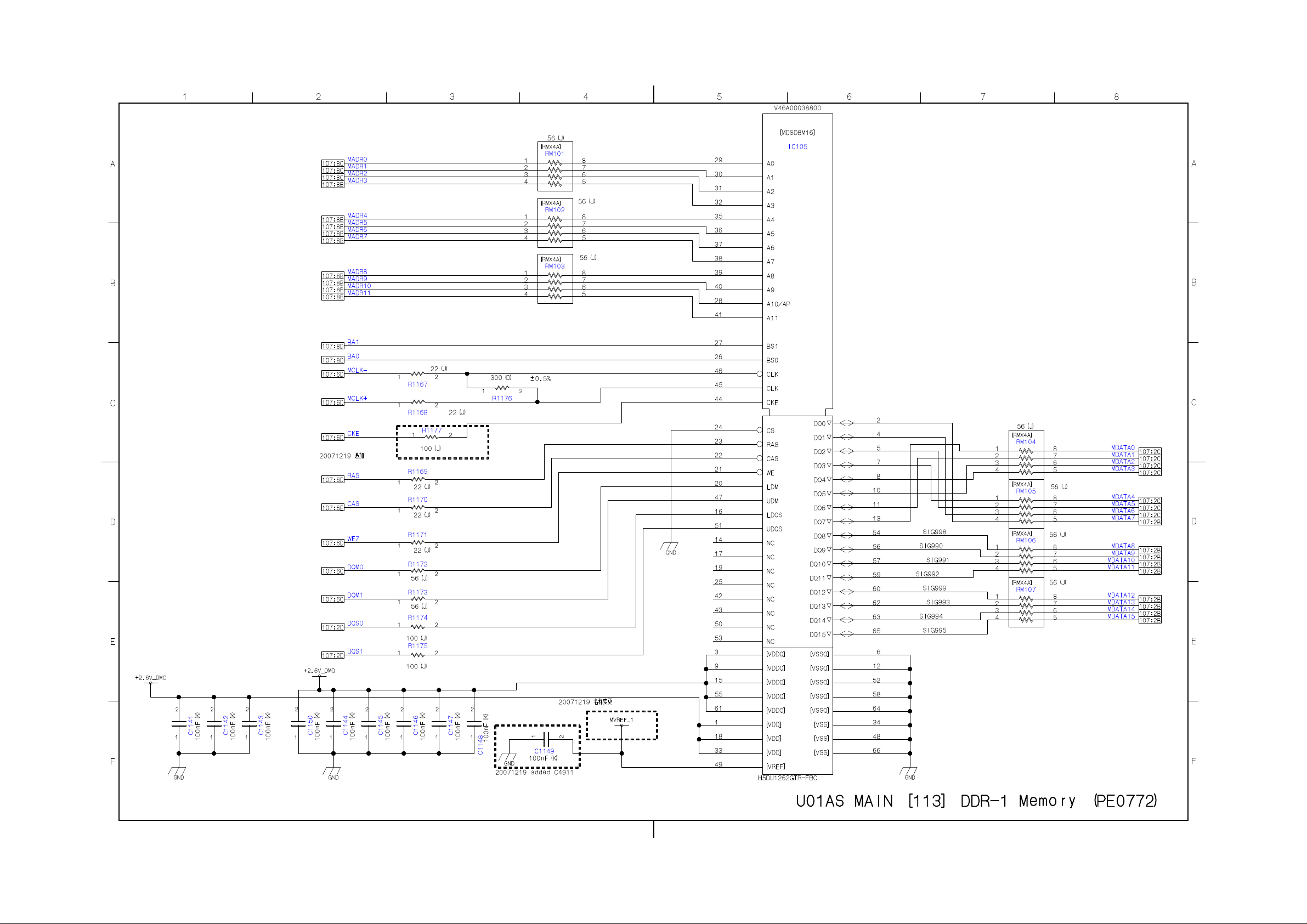
Page 36
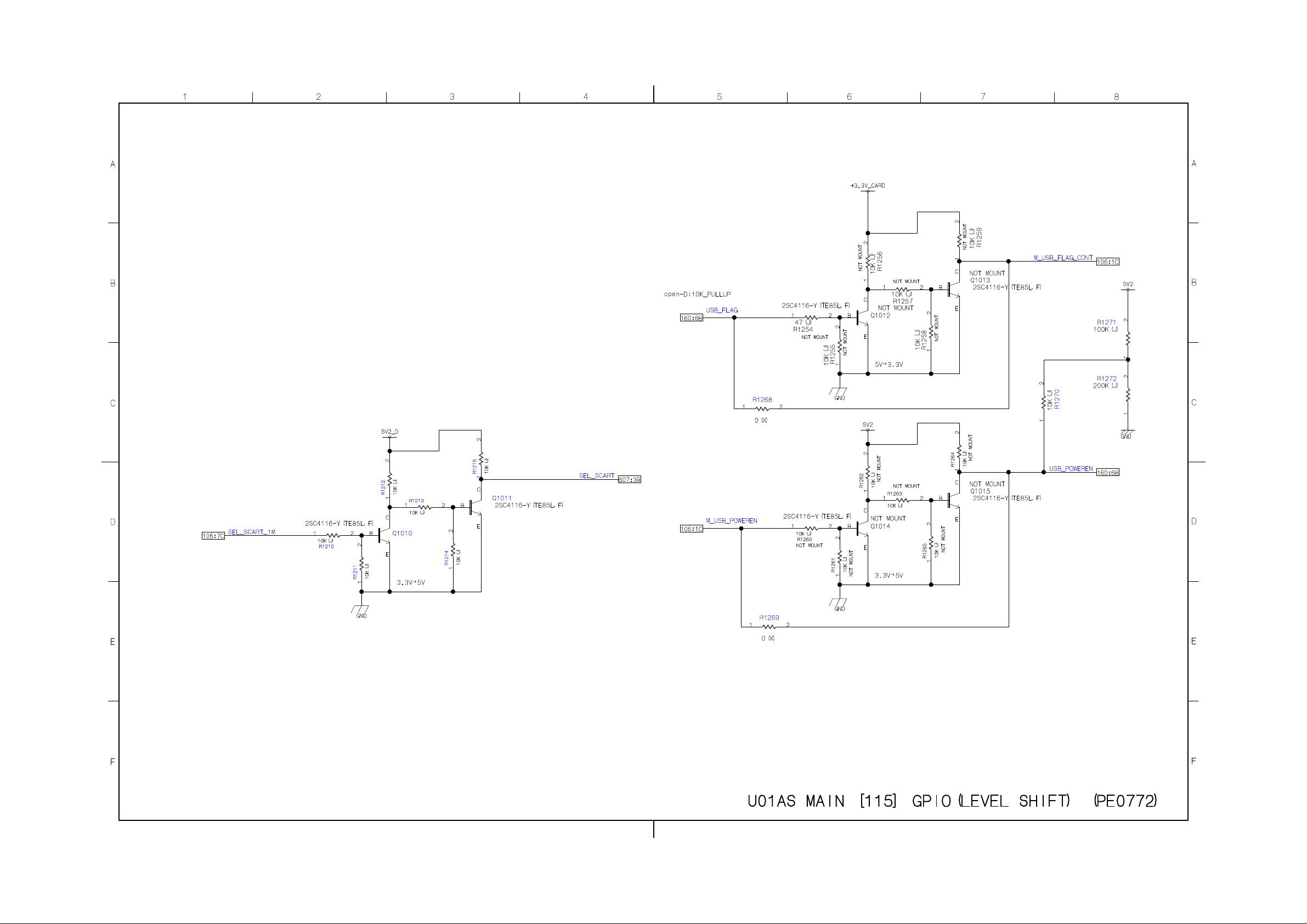
Page 37
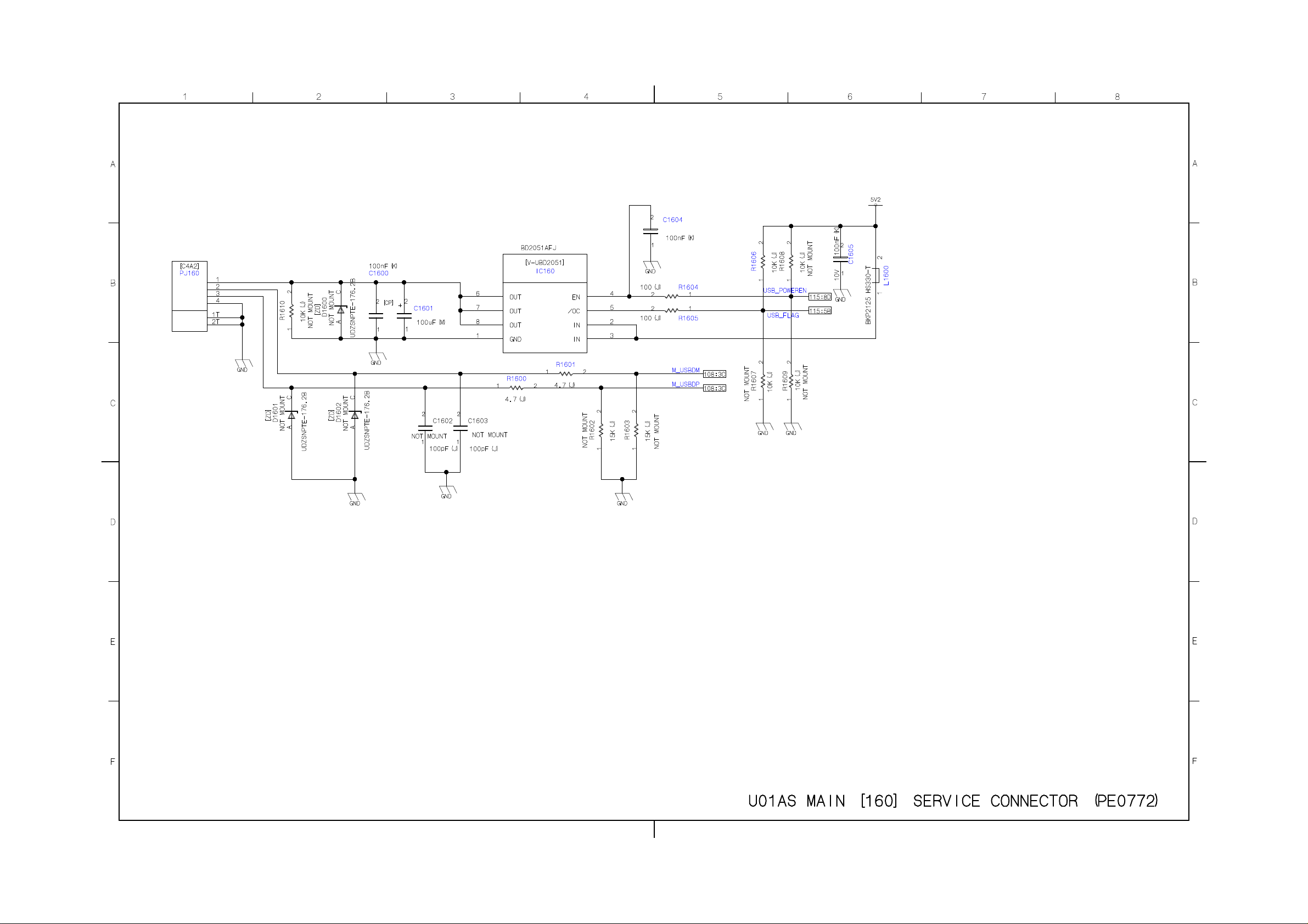
Page 38
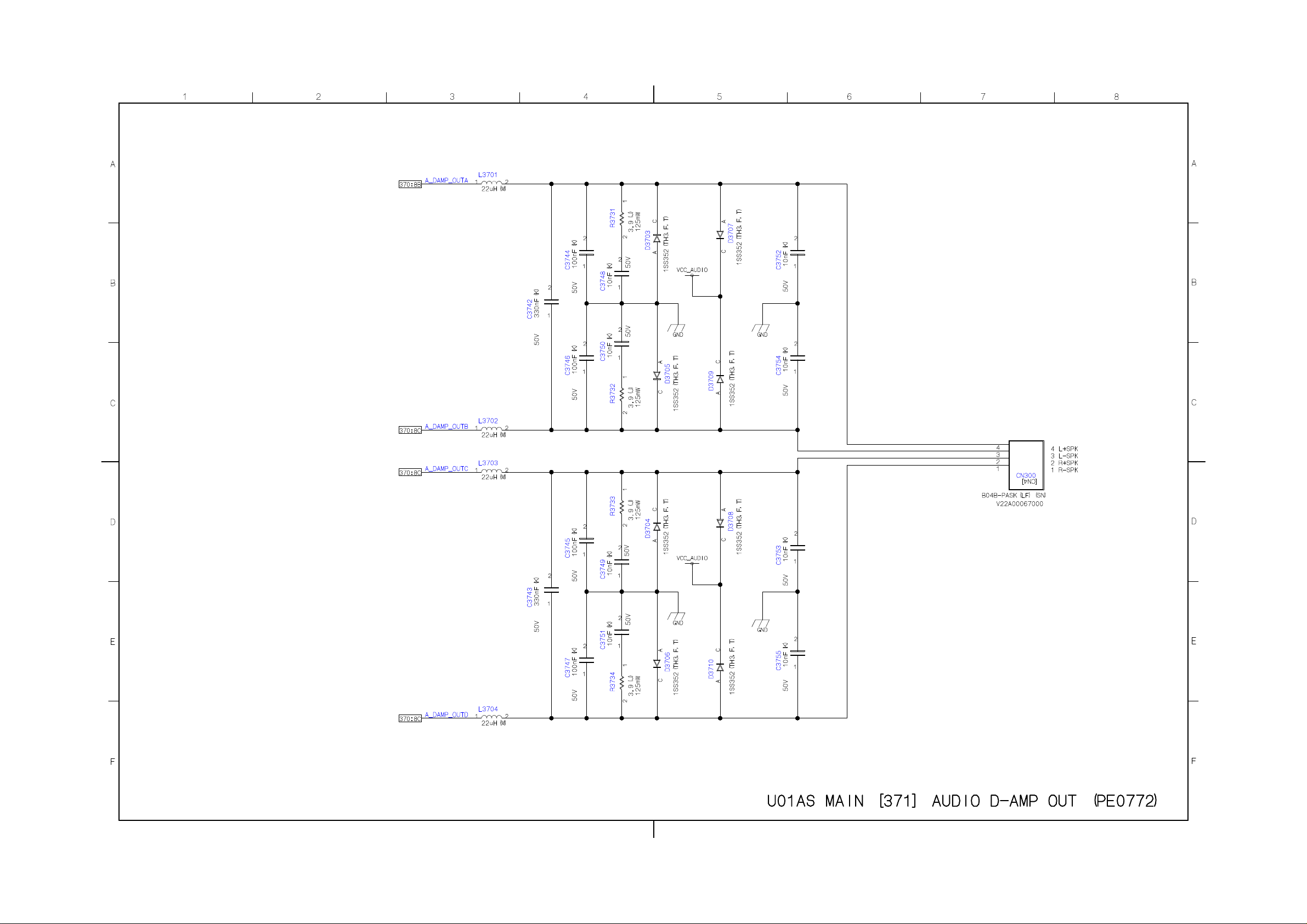
Page 39
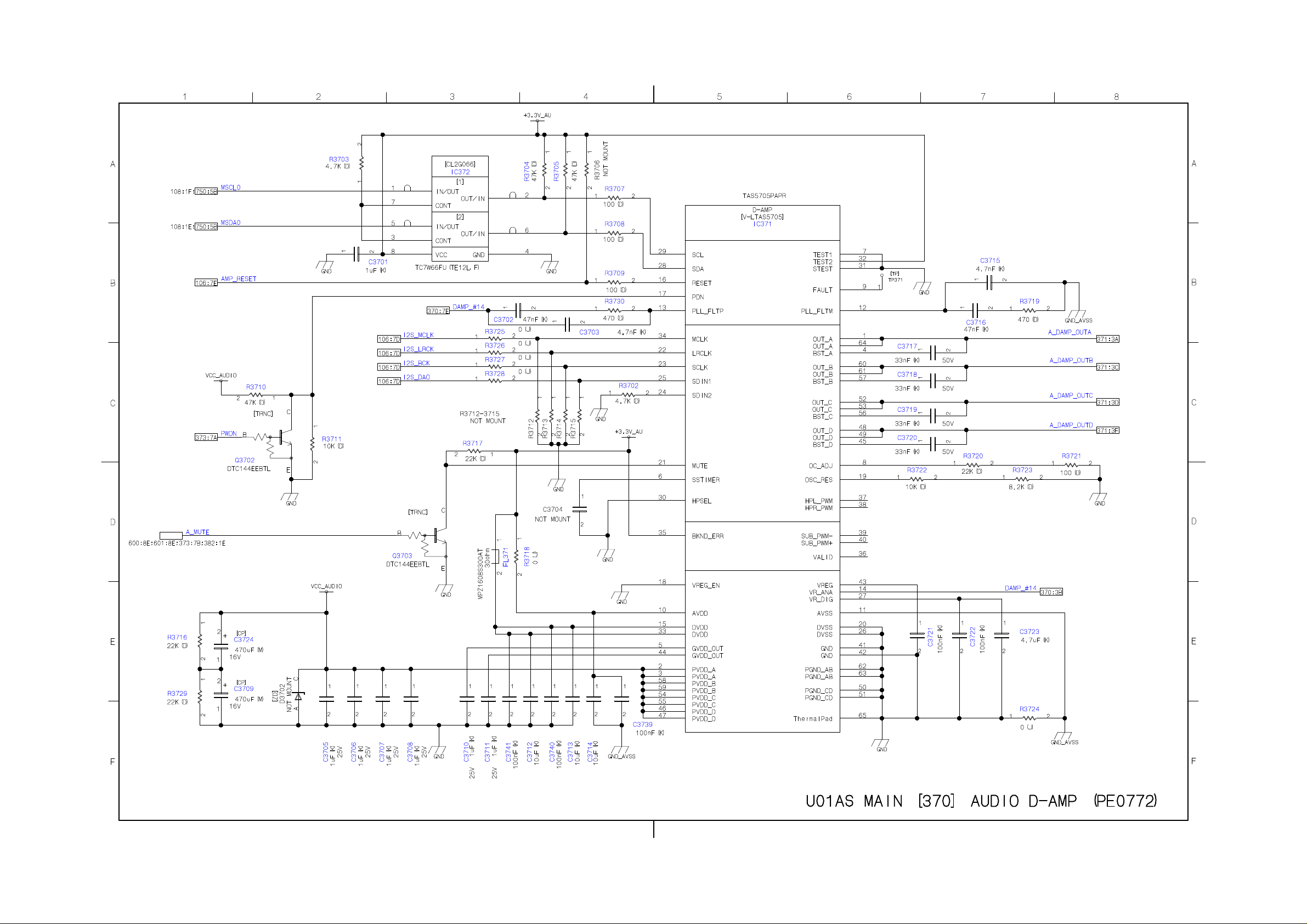
Page 40
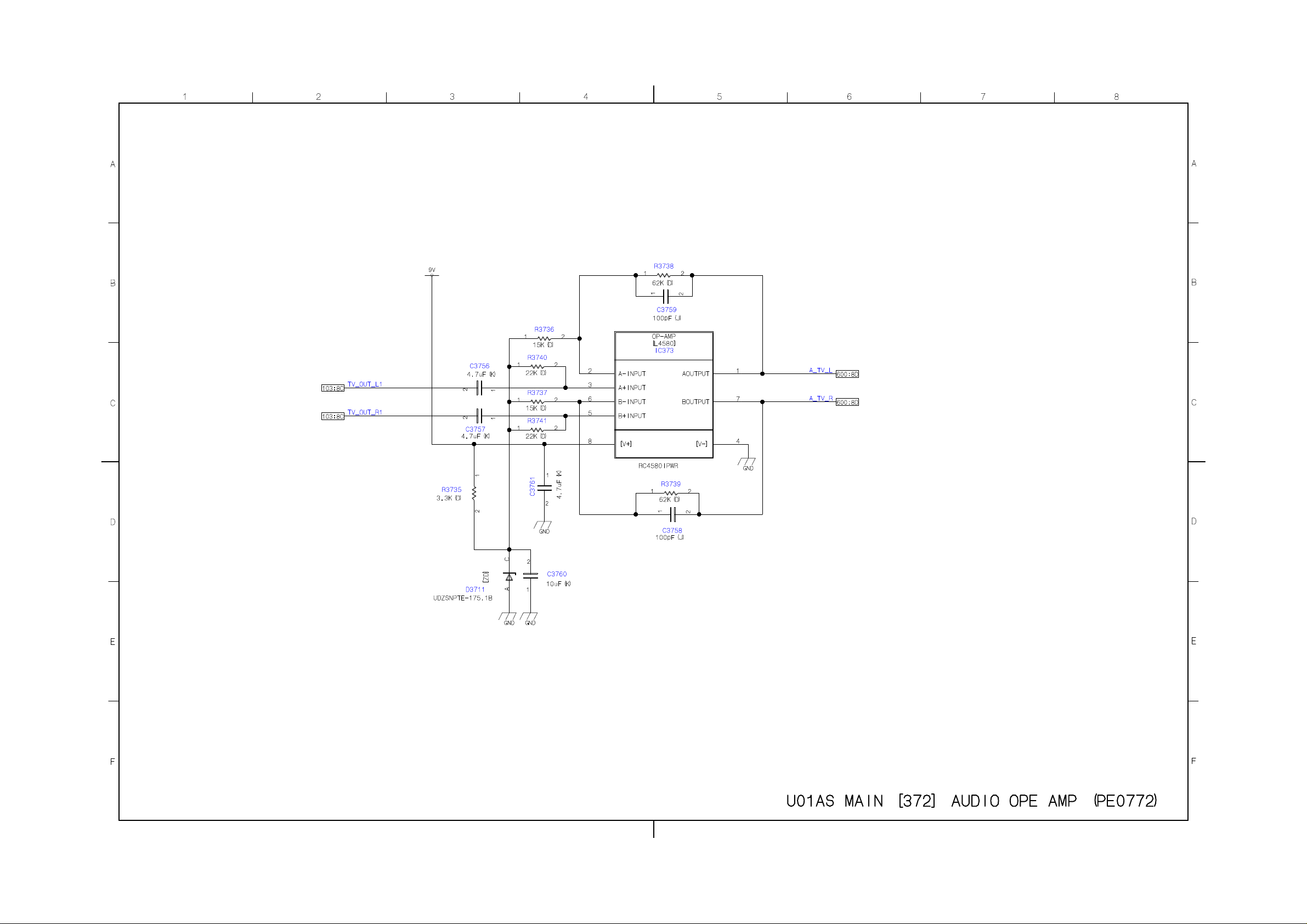
Page 41
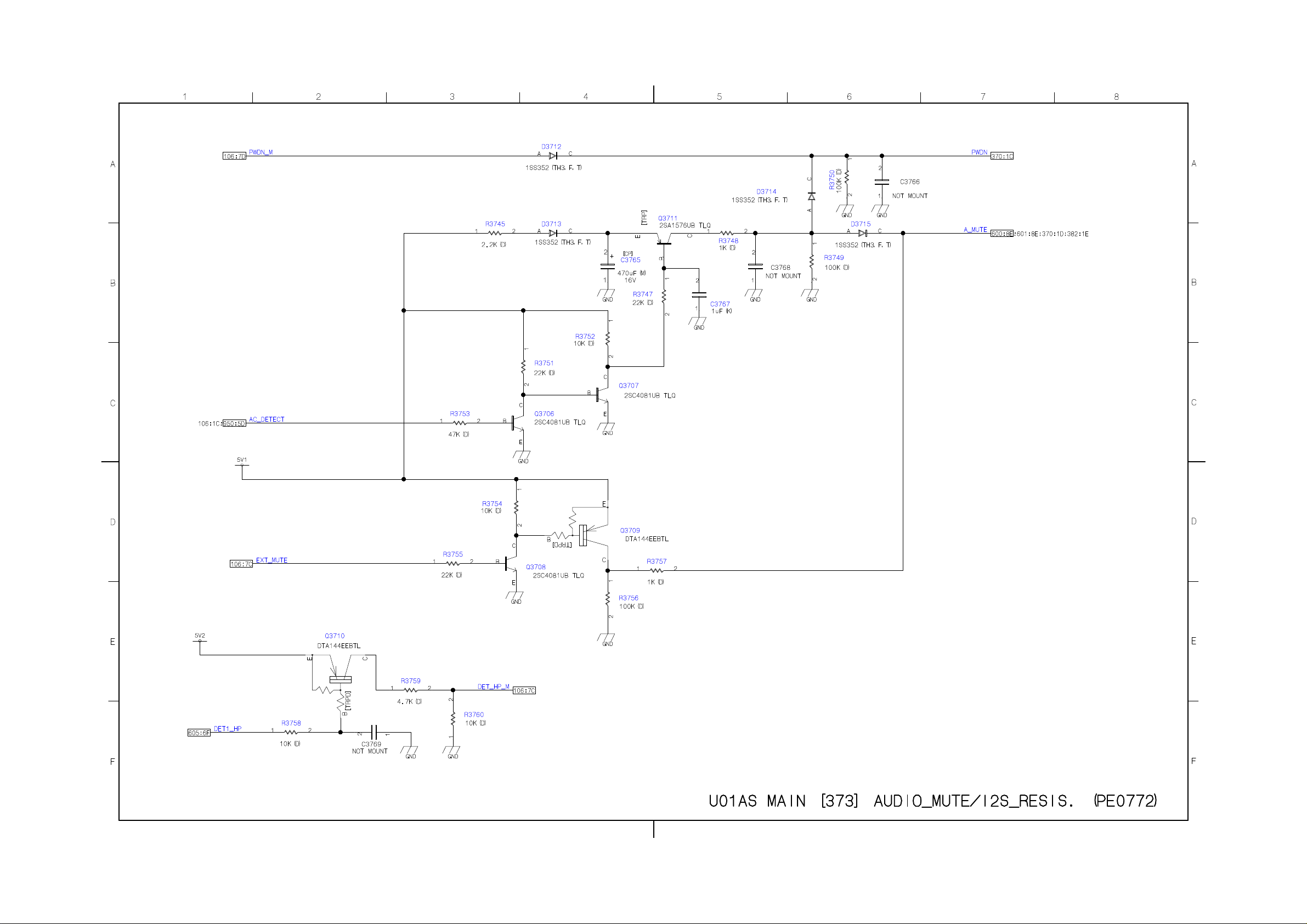
Page 42
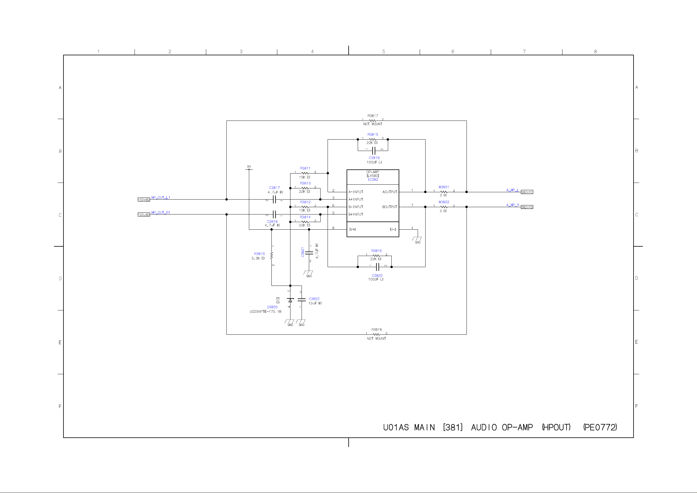
Page 43
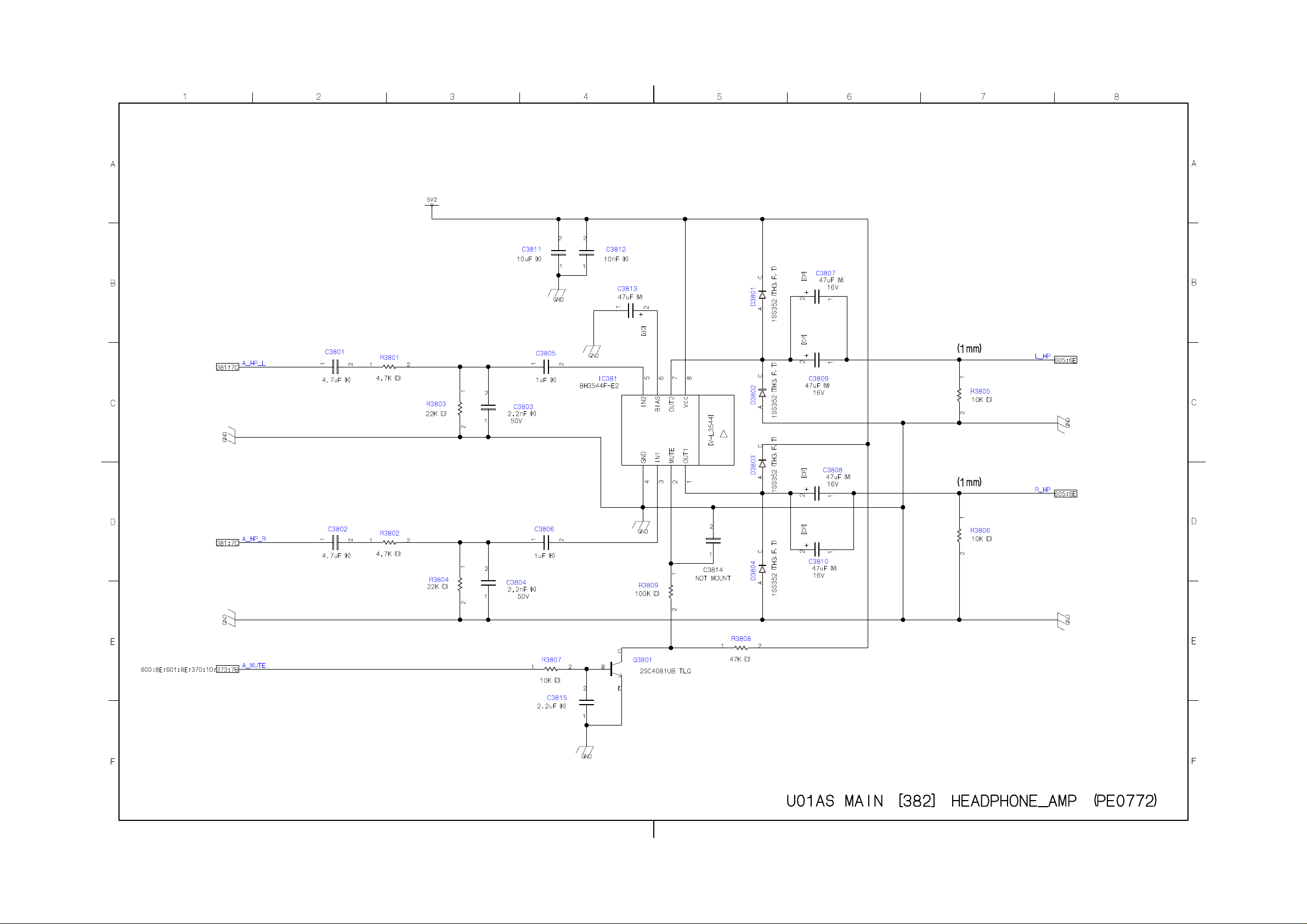
Page 44
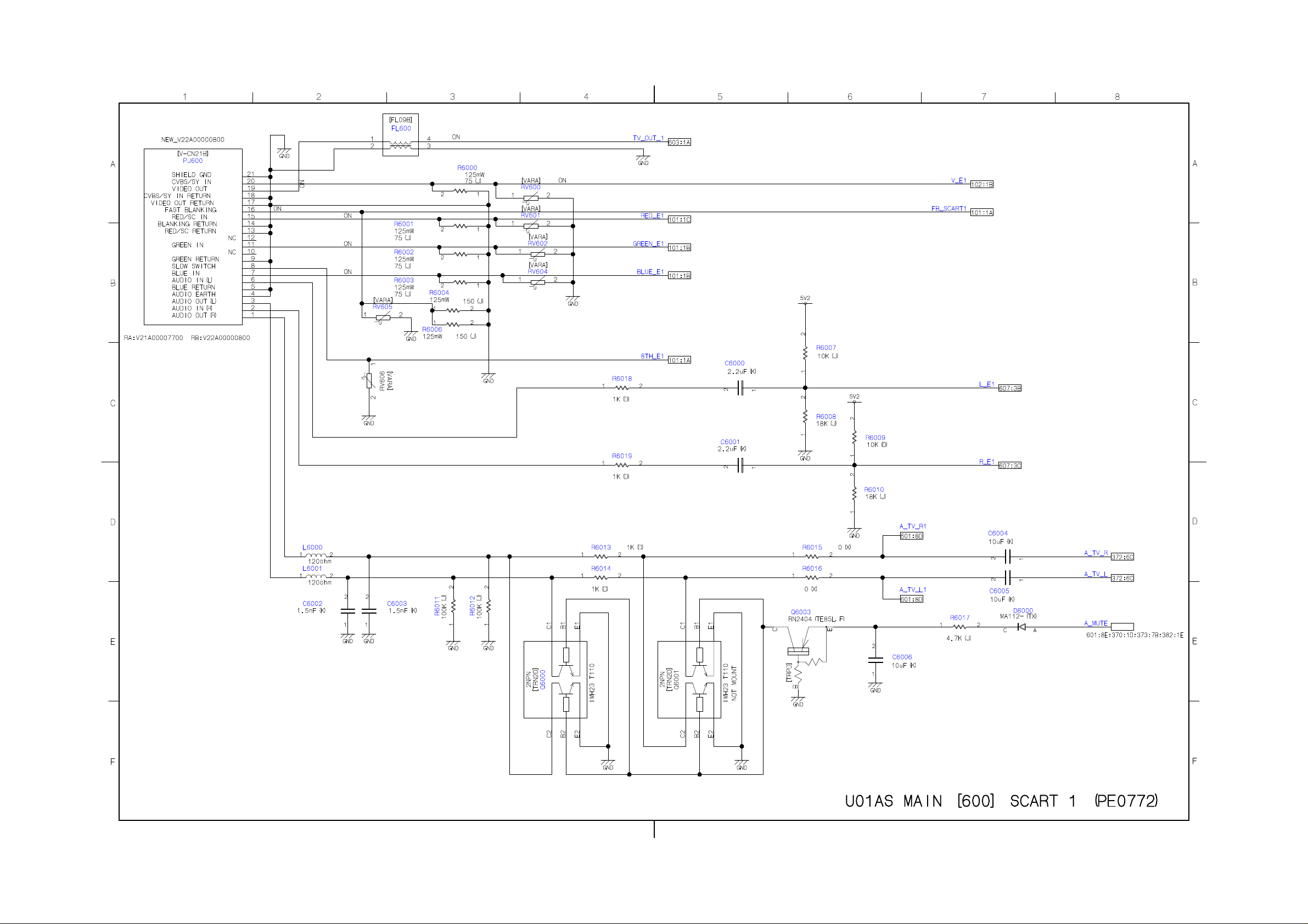
Page 45
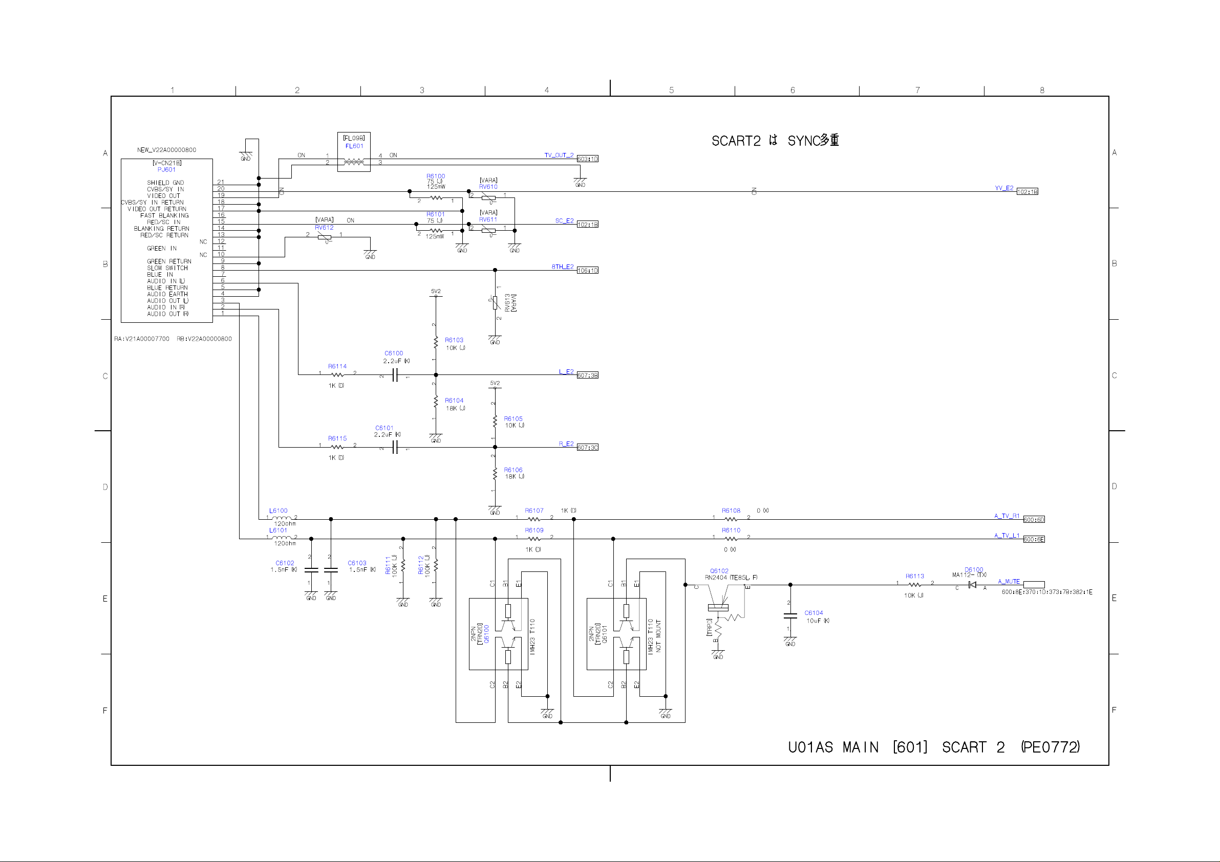
Page 46
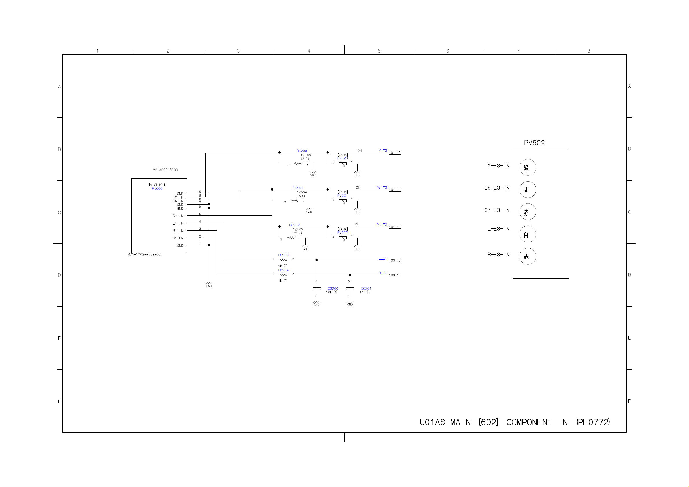
Page 47
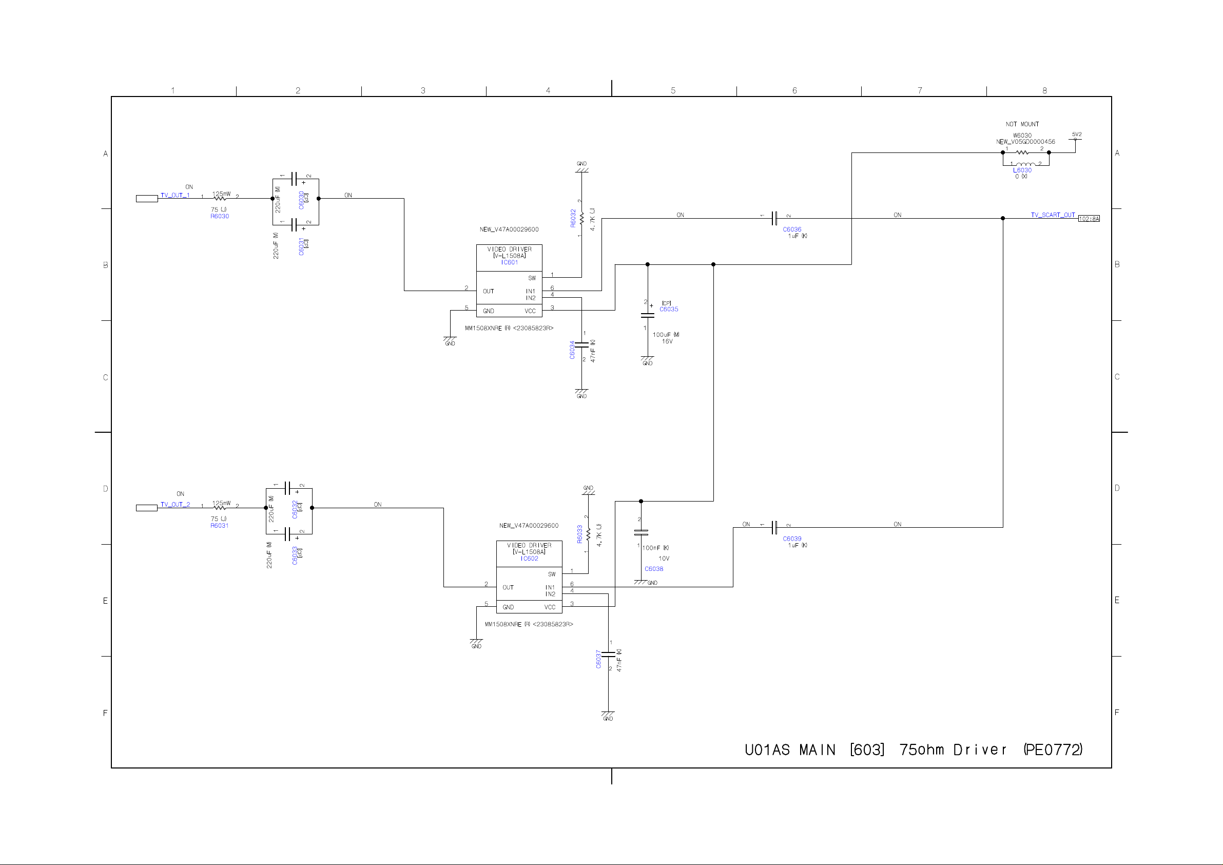
Page 48
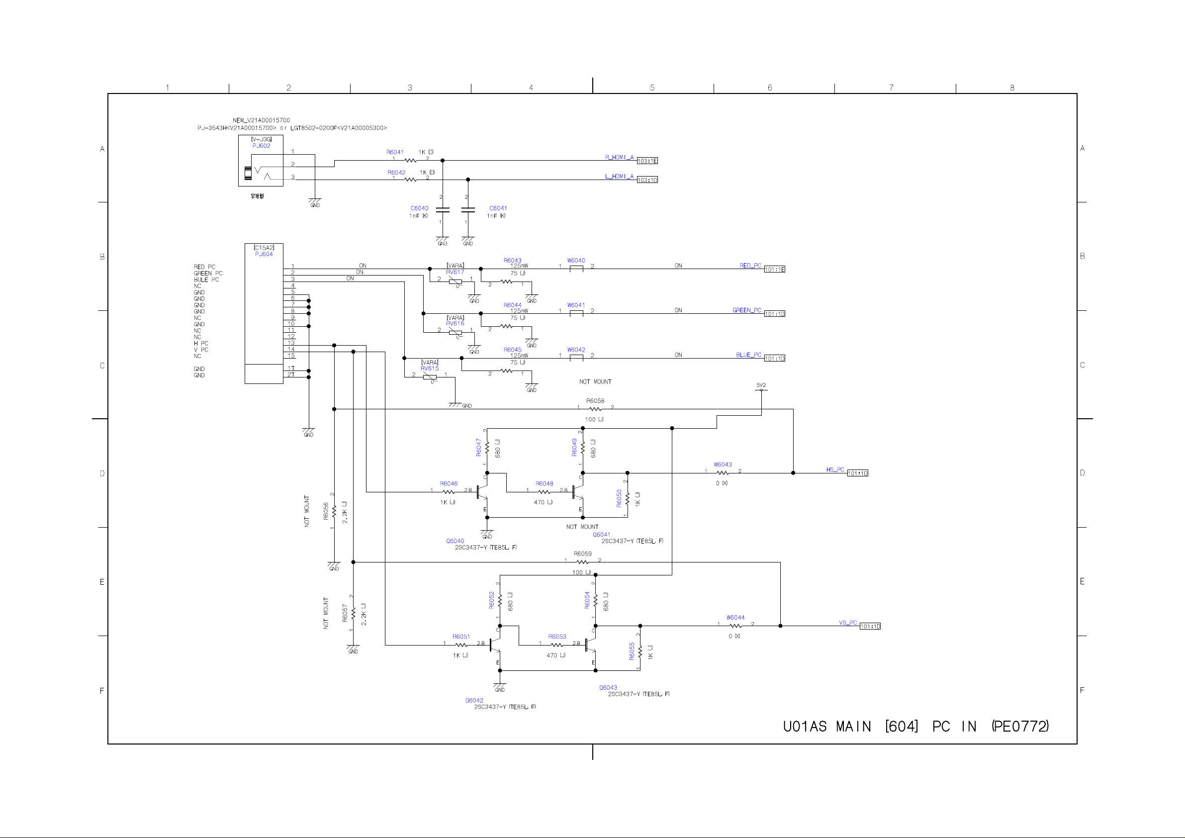
Page 49
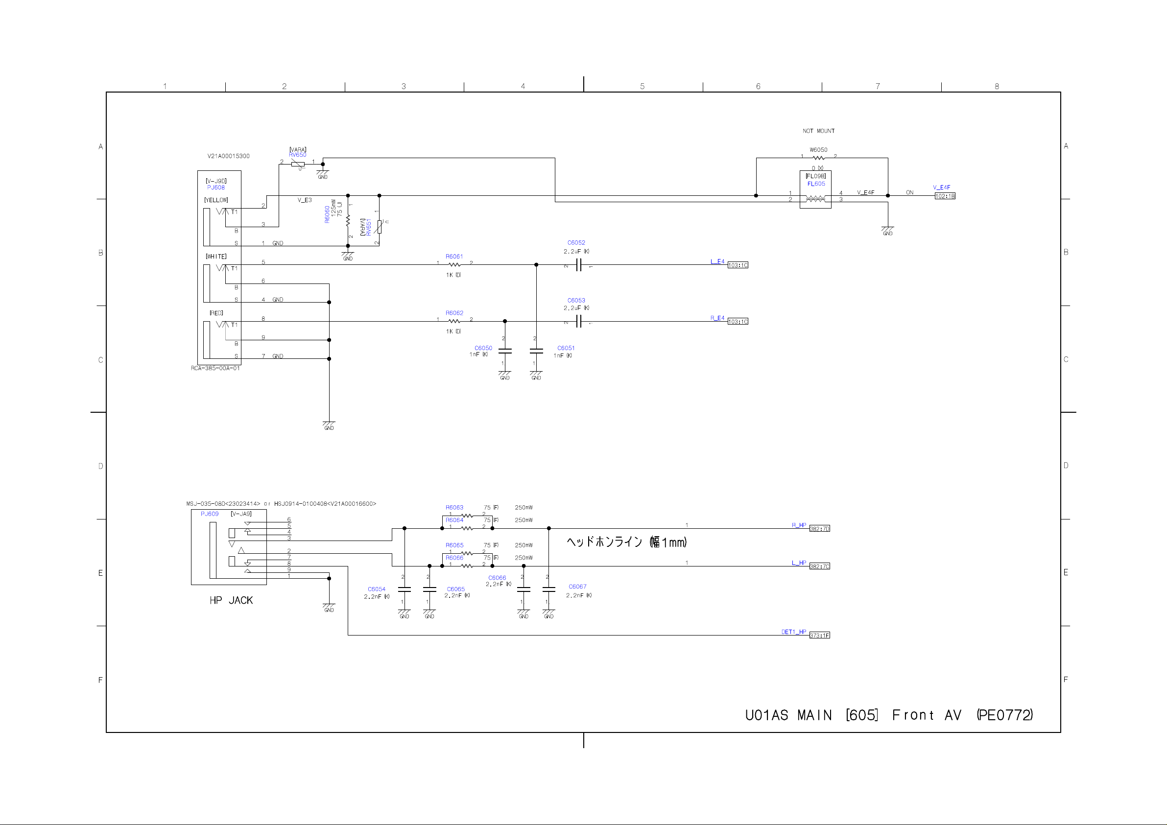
Page 50
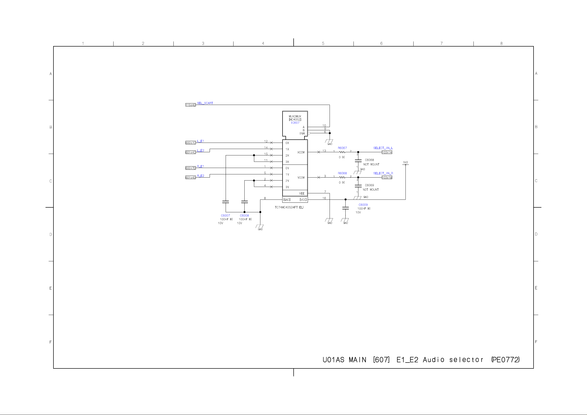
Page 51
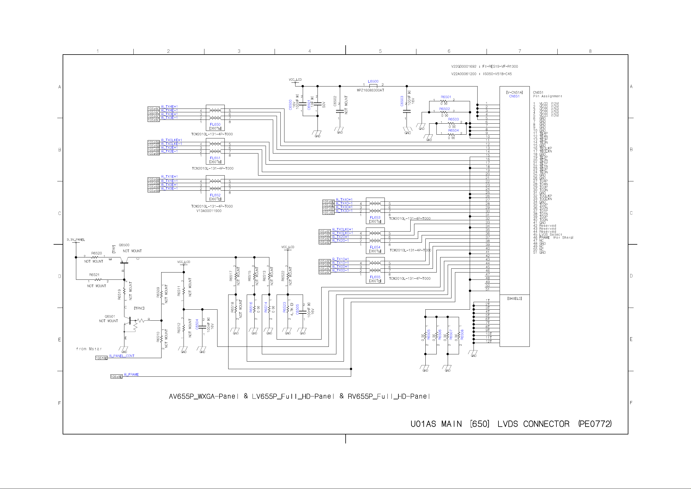
Page 52
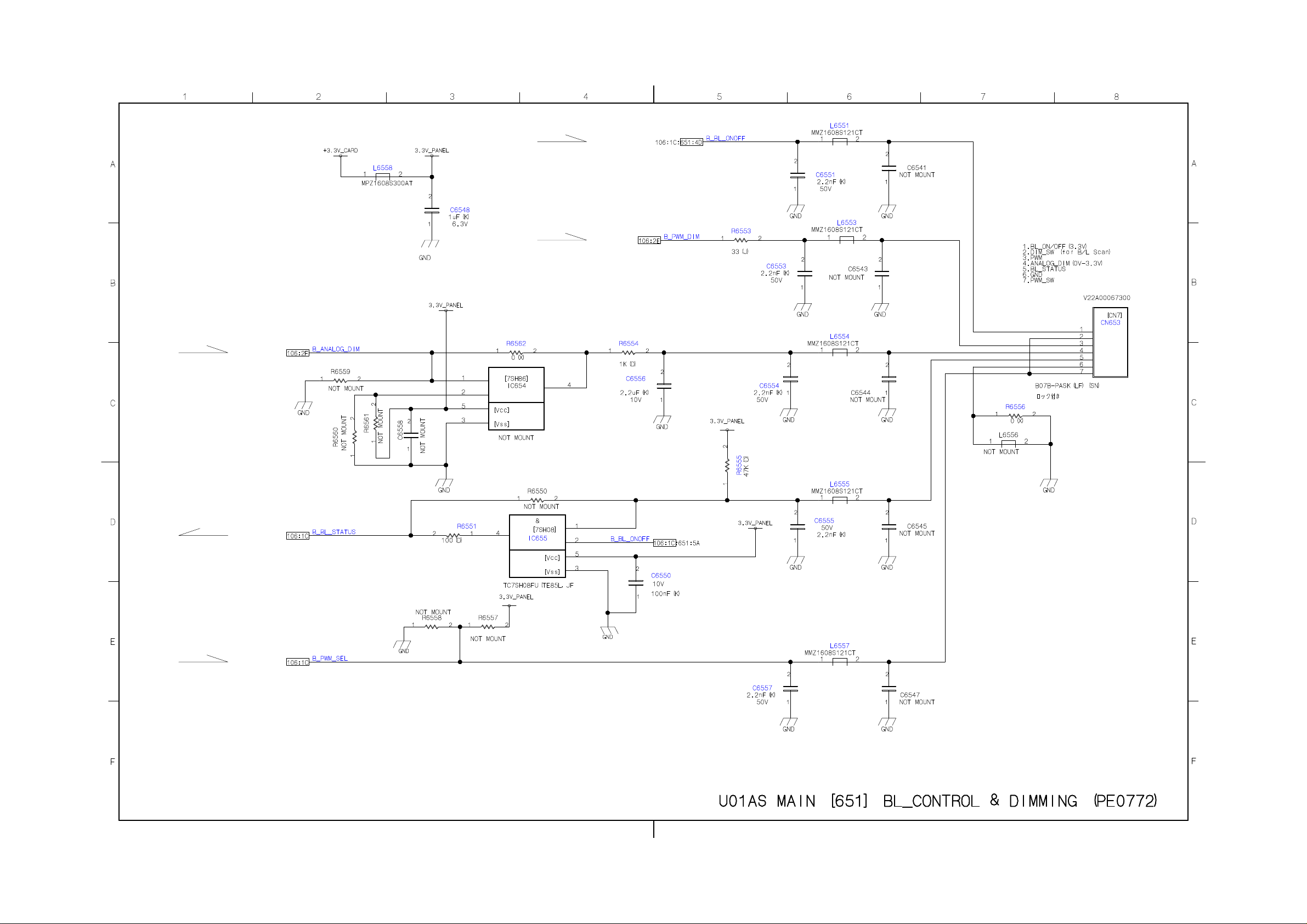
Page 53
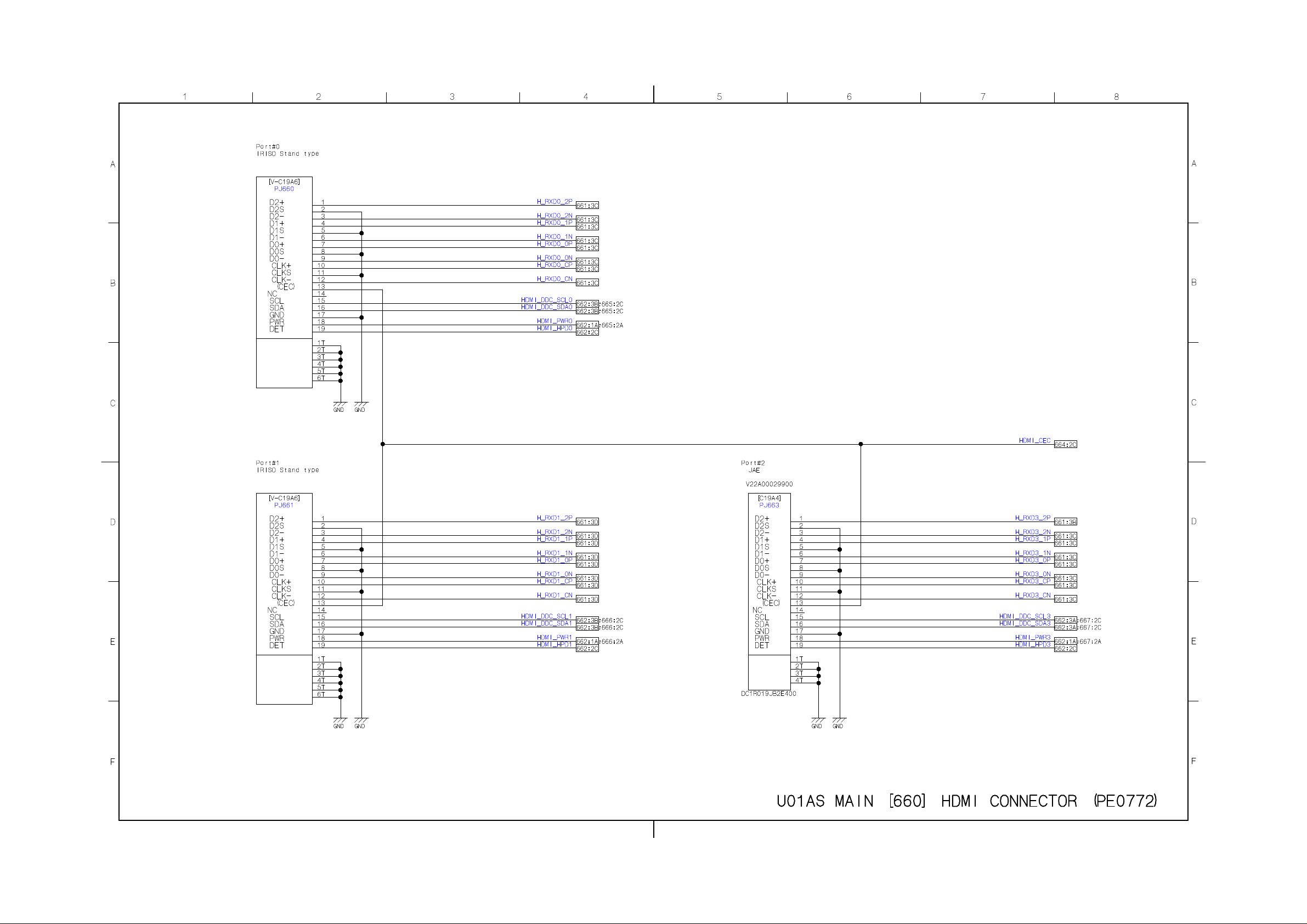
Page 54
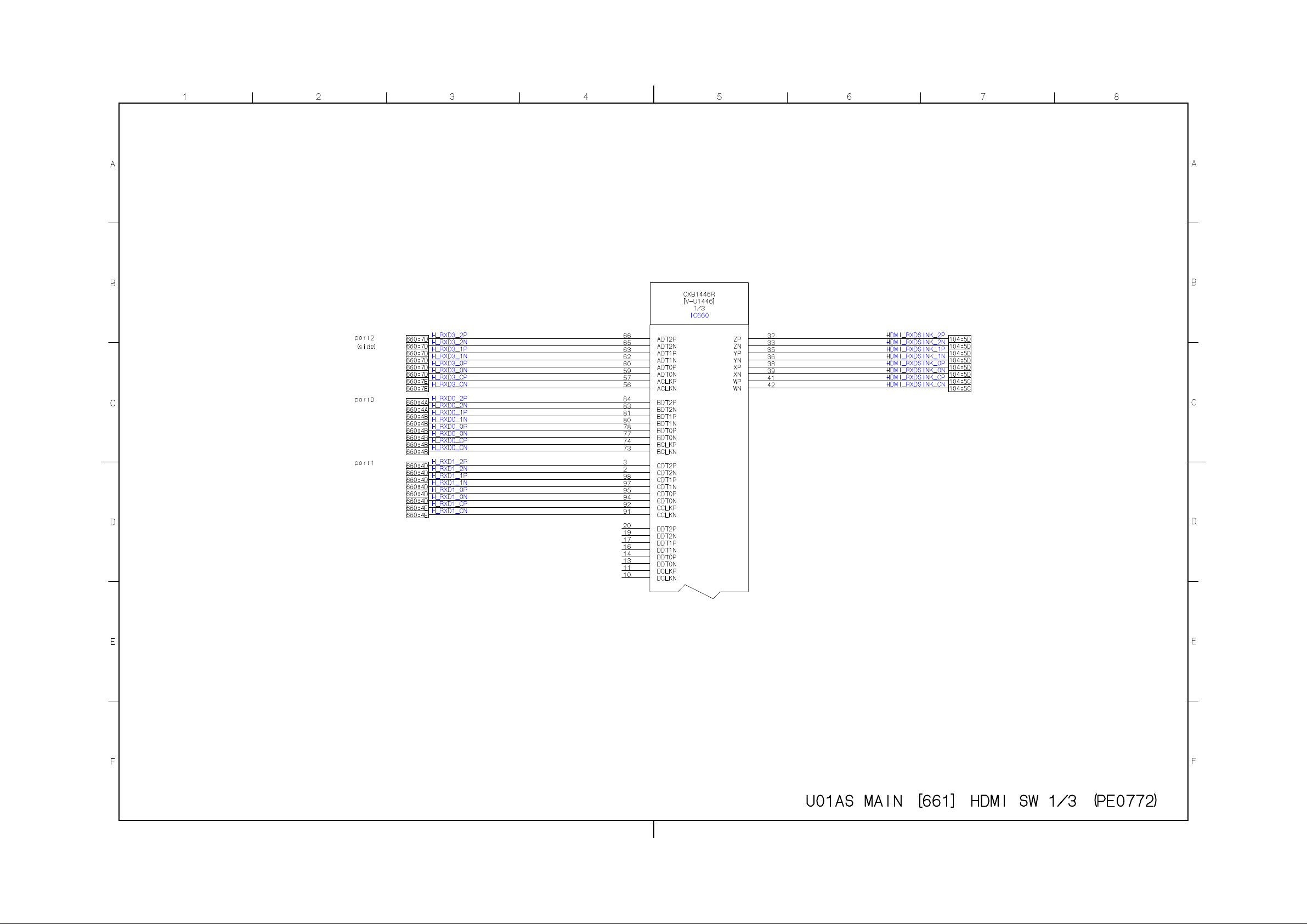
Page 55
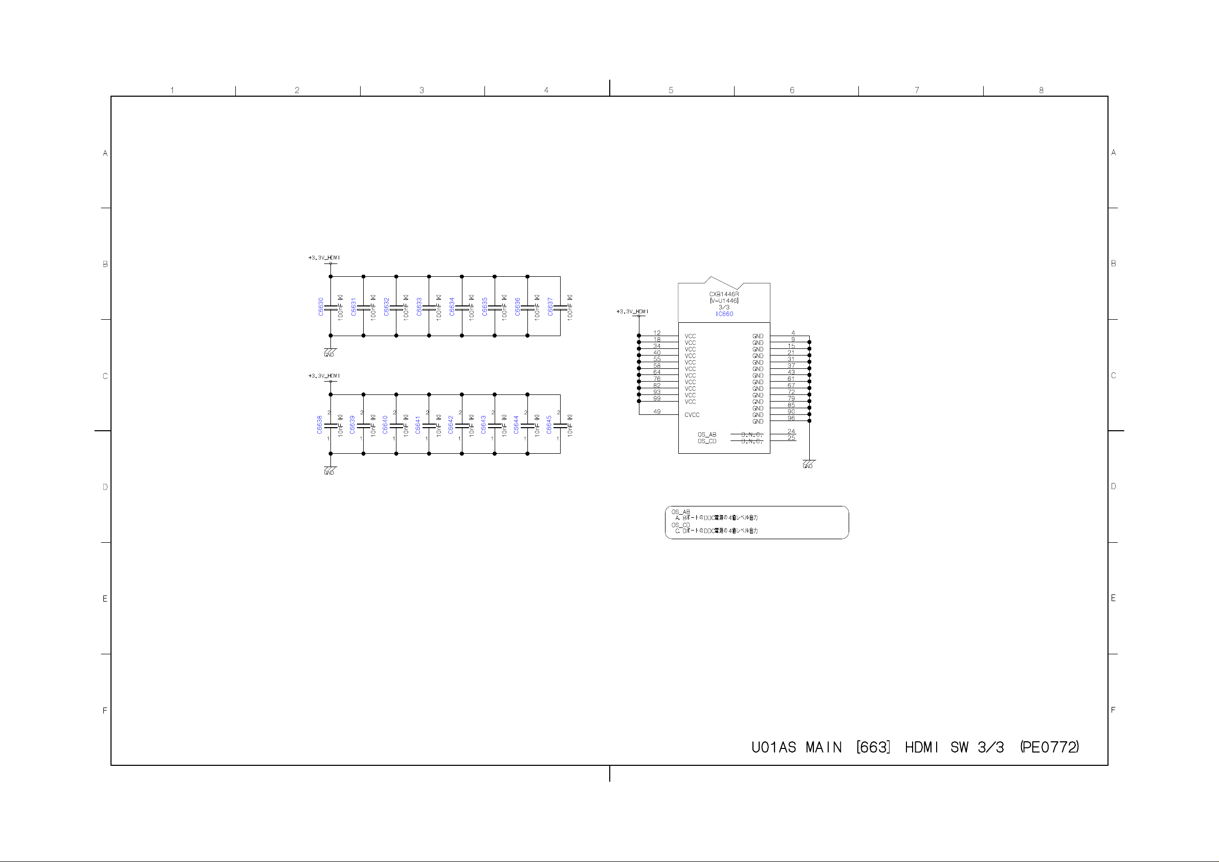
Page 56
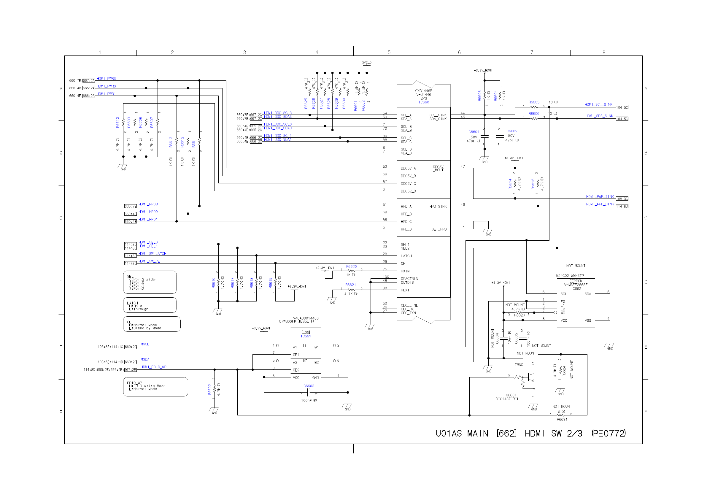
Page 57
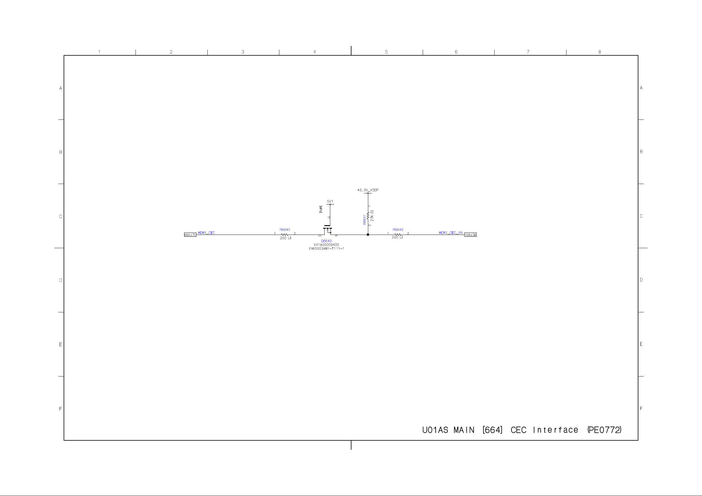
Page 58
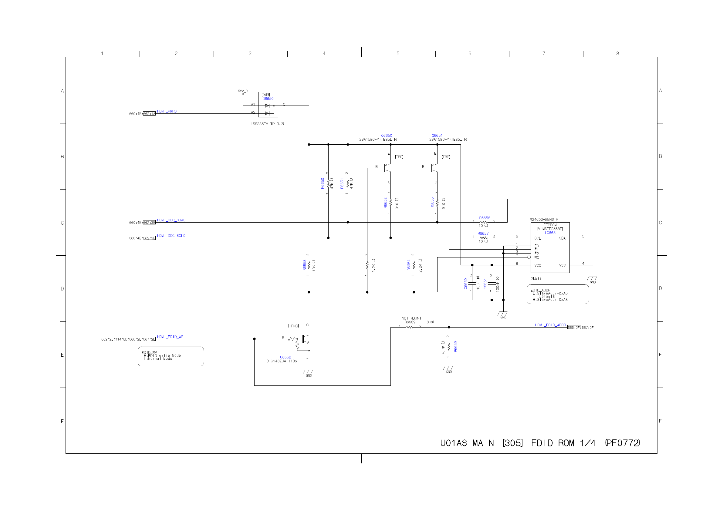
Page 59
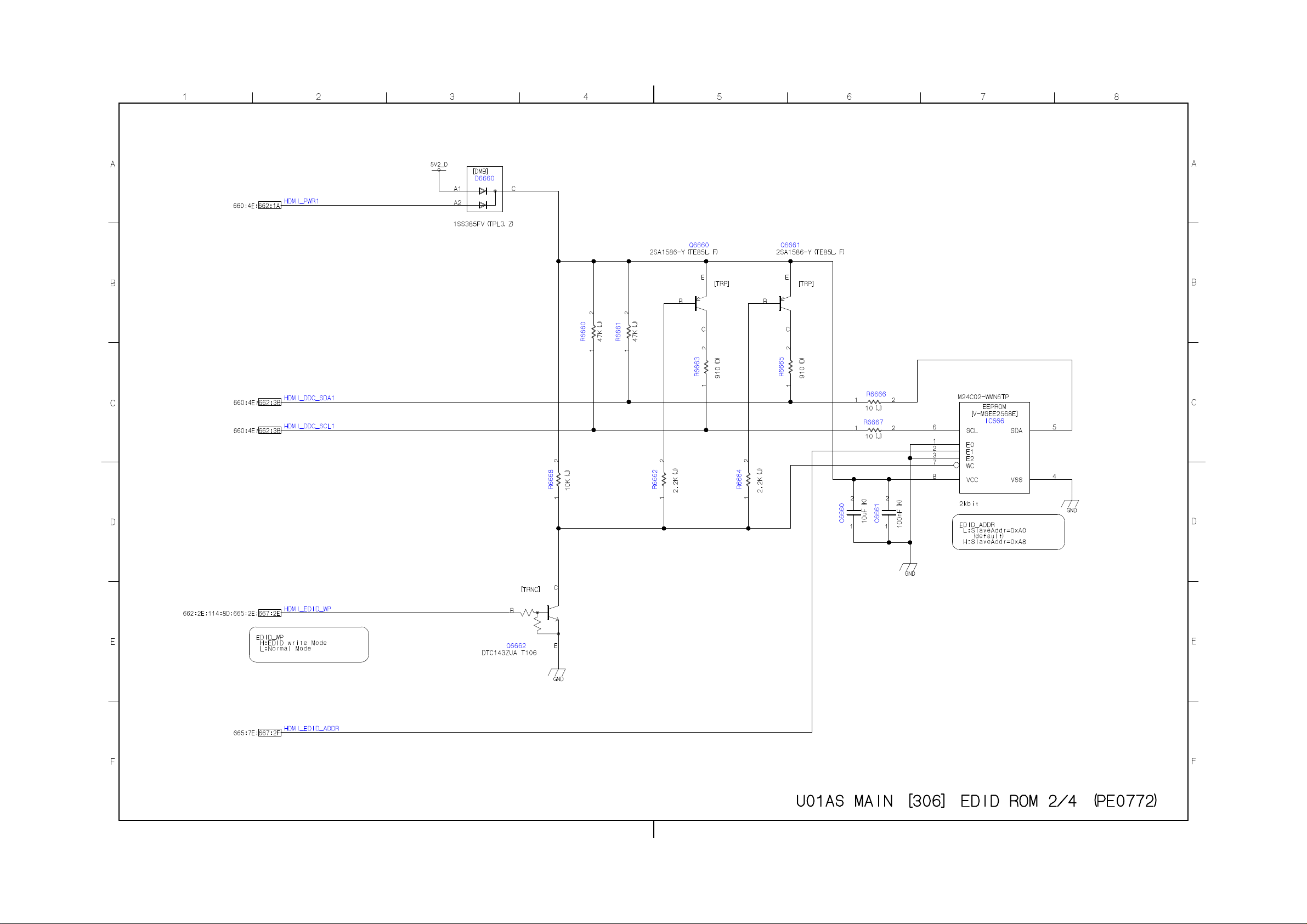
Page 60
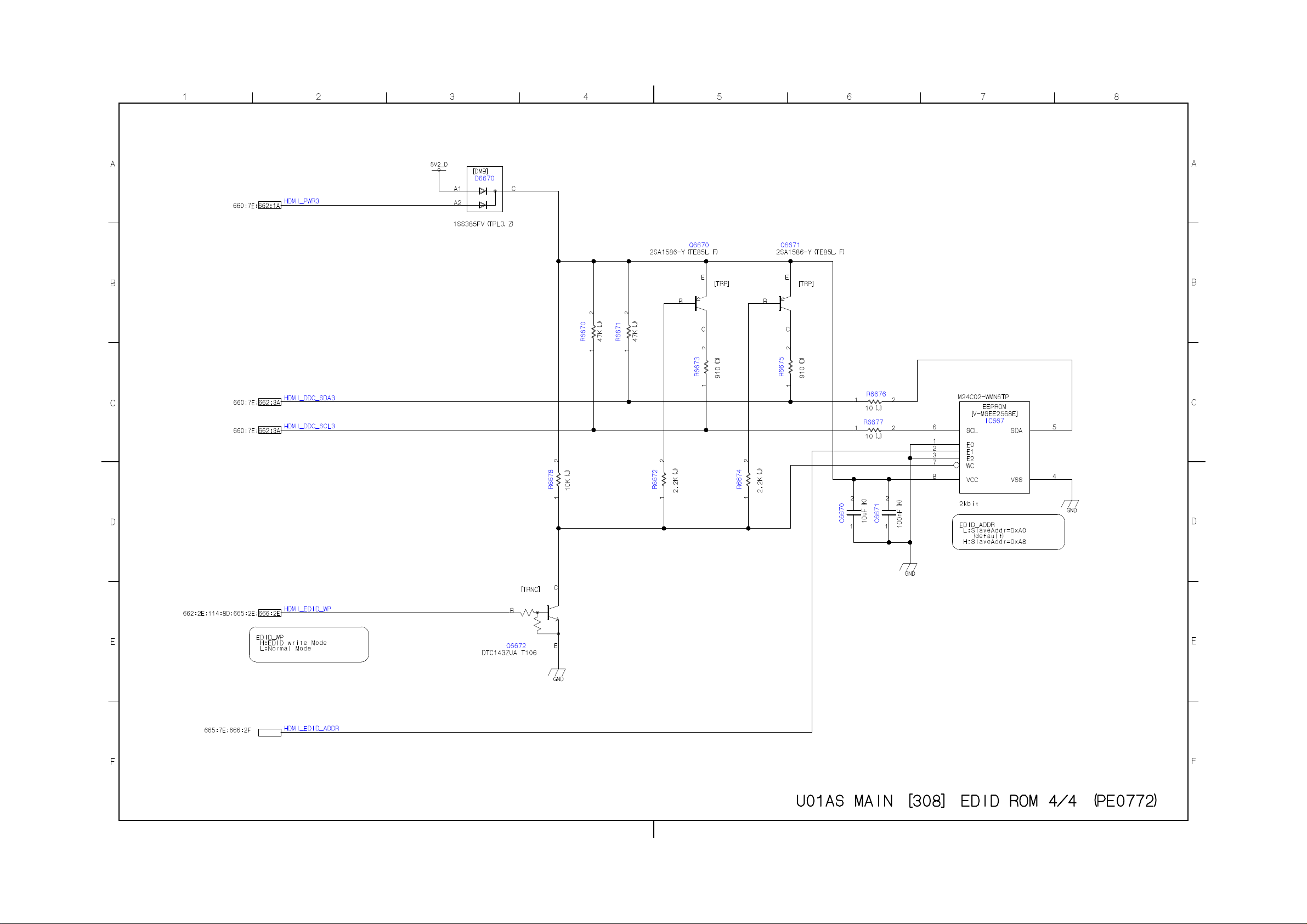
Page 61
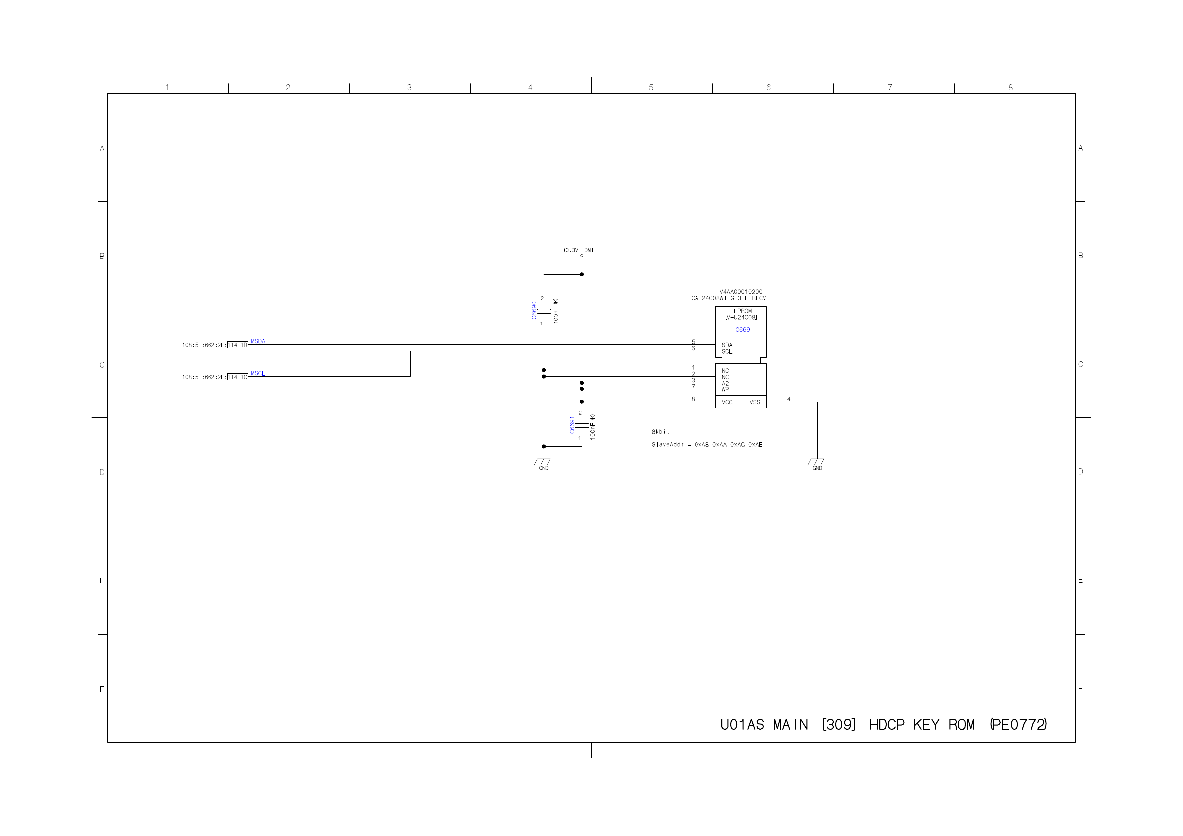
Page 62
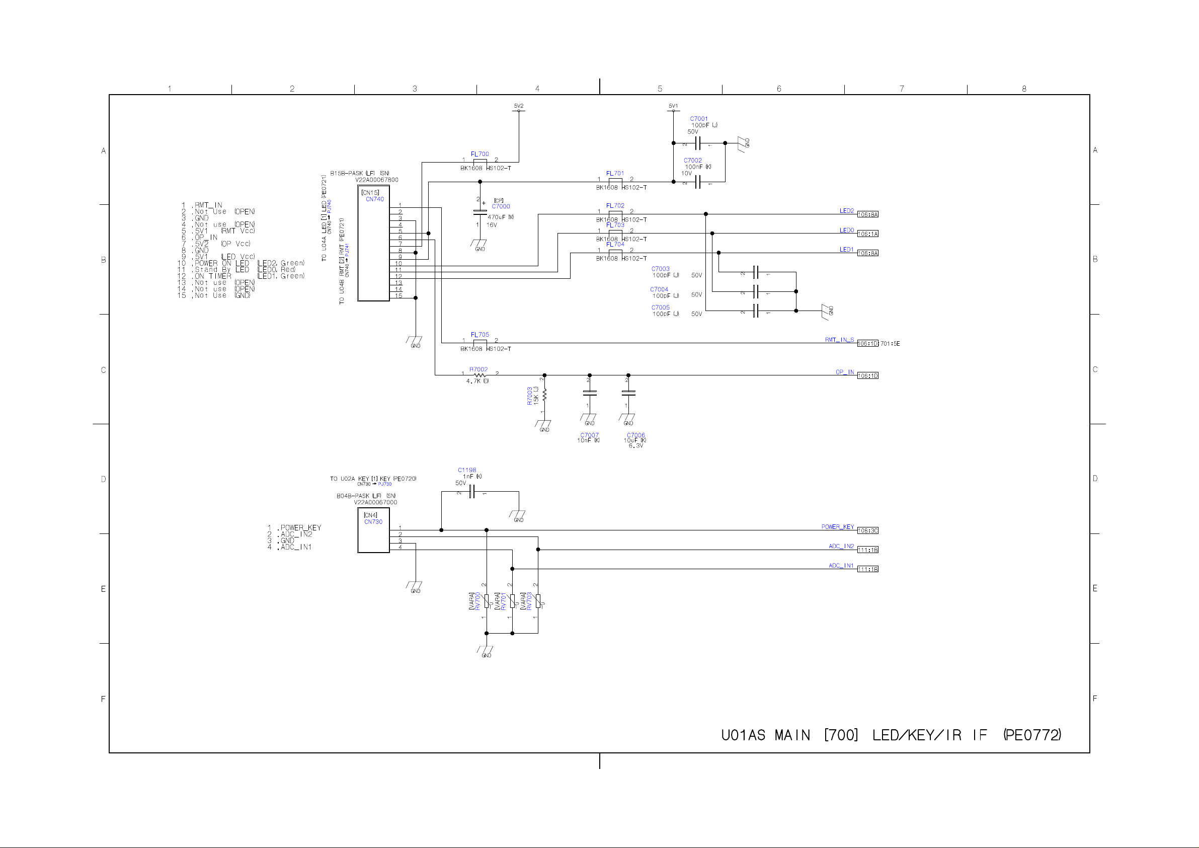
Page 63
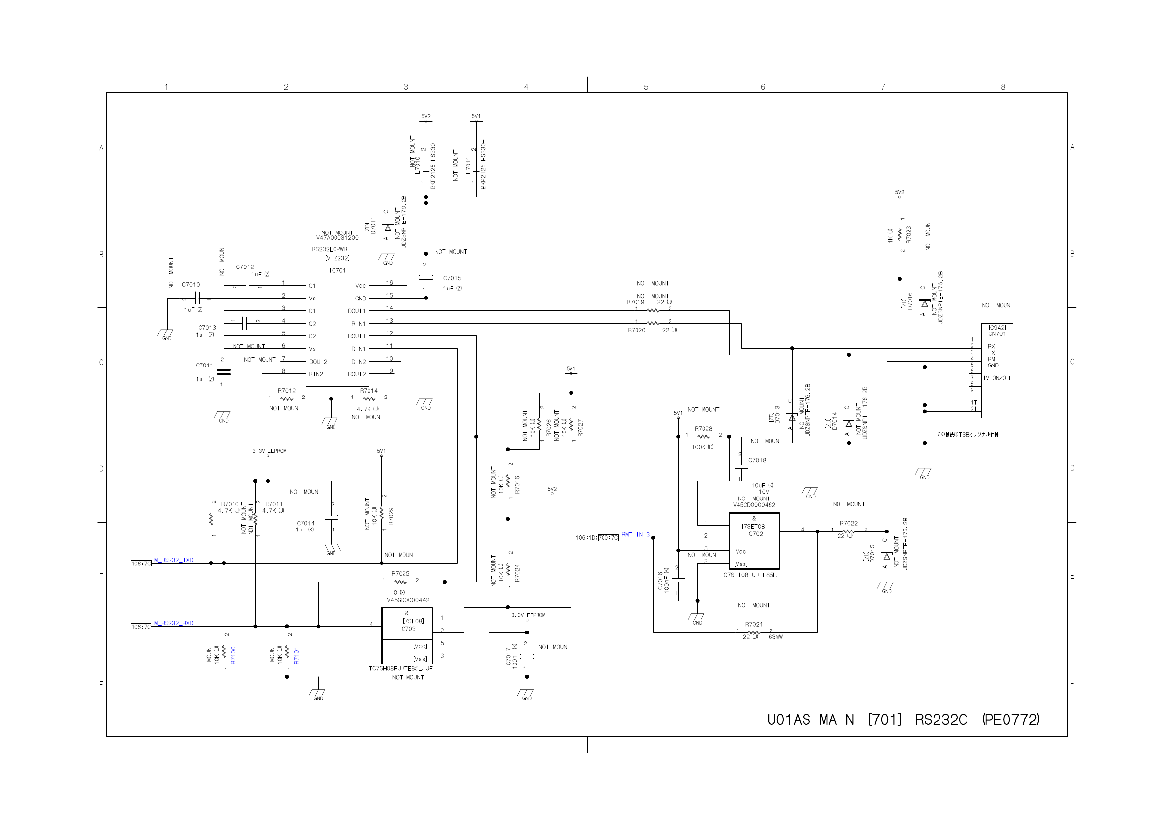
Page 64
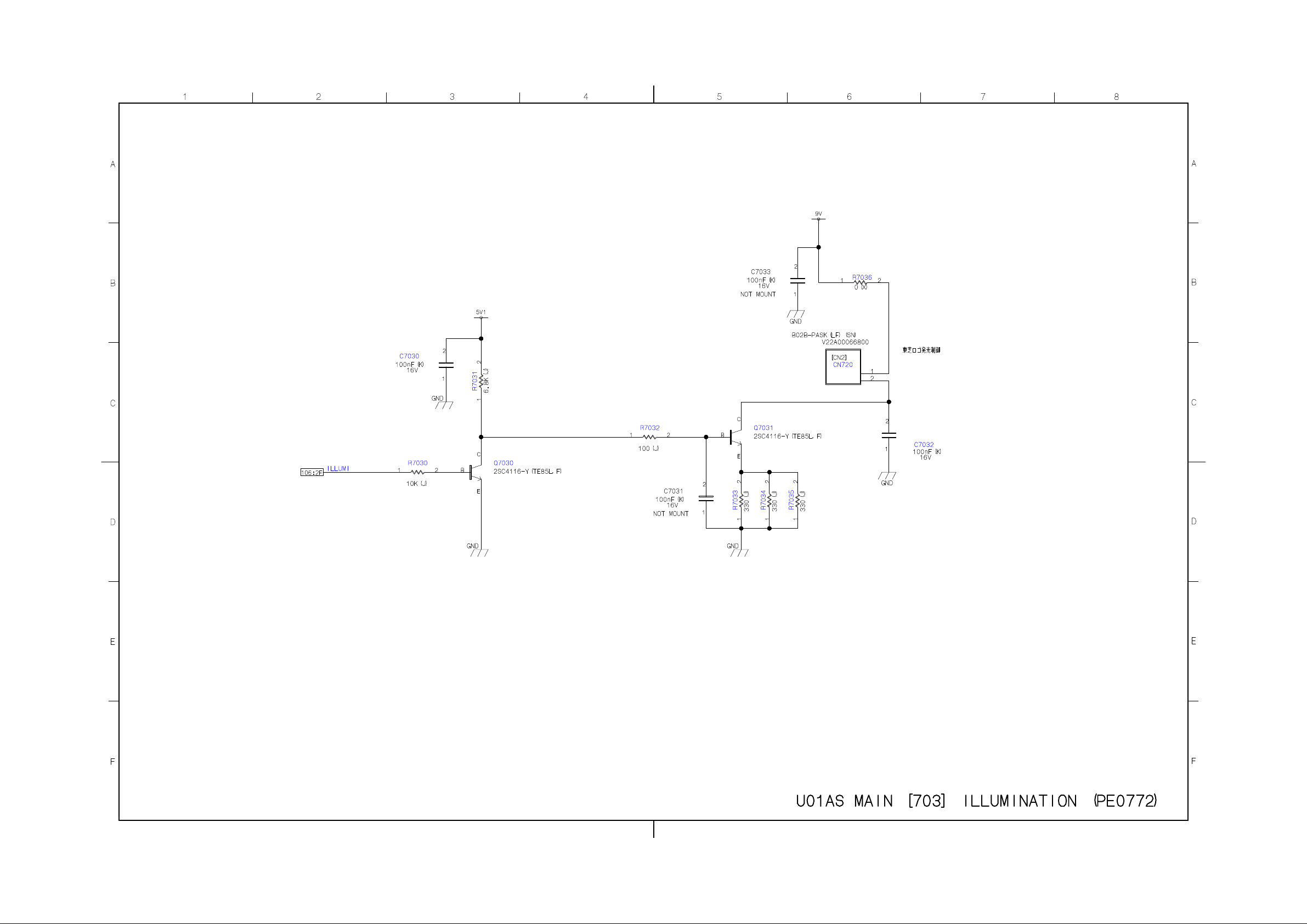
Page 65
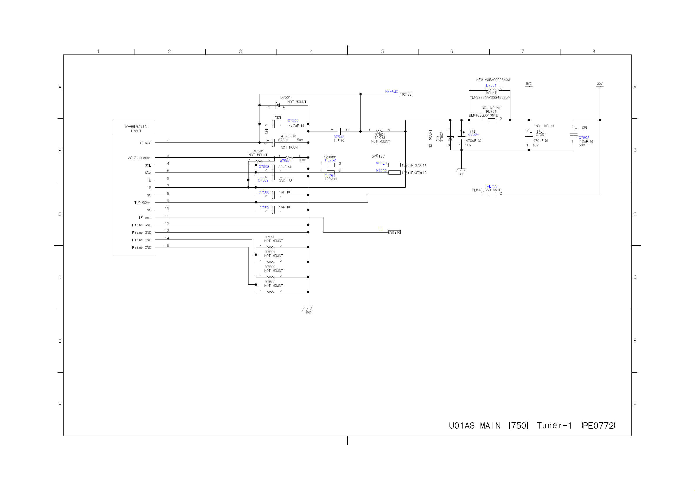
Page 66
Page 67
Page 68
Page 69
Page 70
Page 71
Page 72
Page 73
Page 74
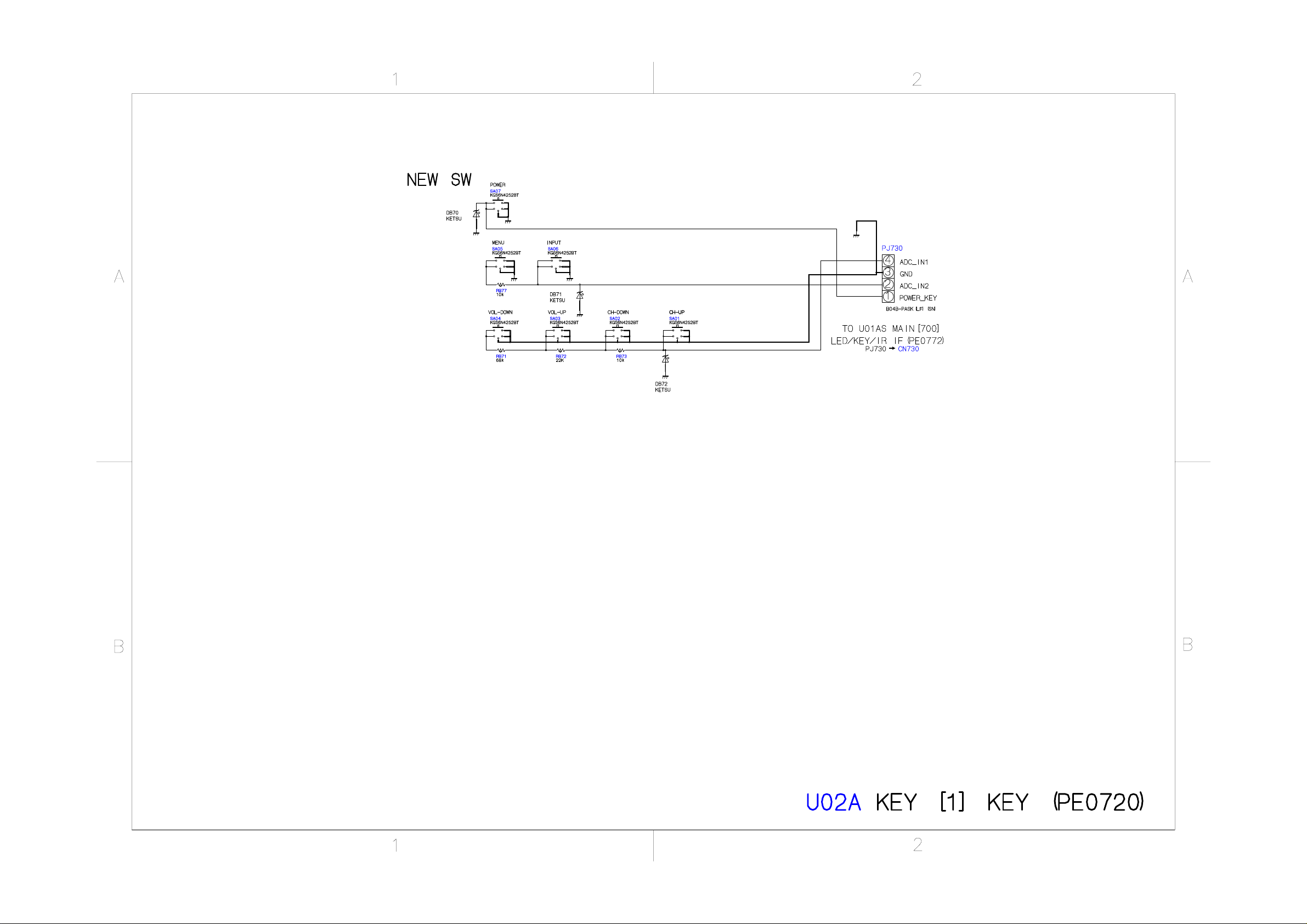
Page 75
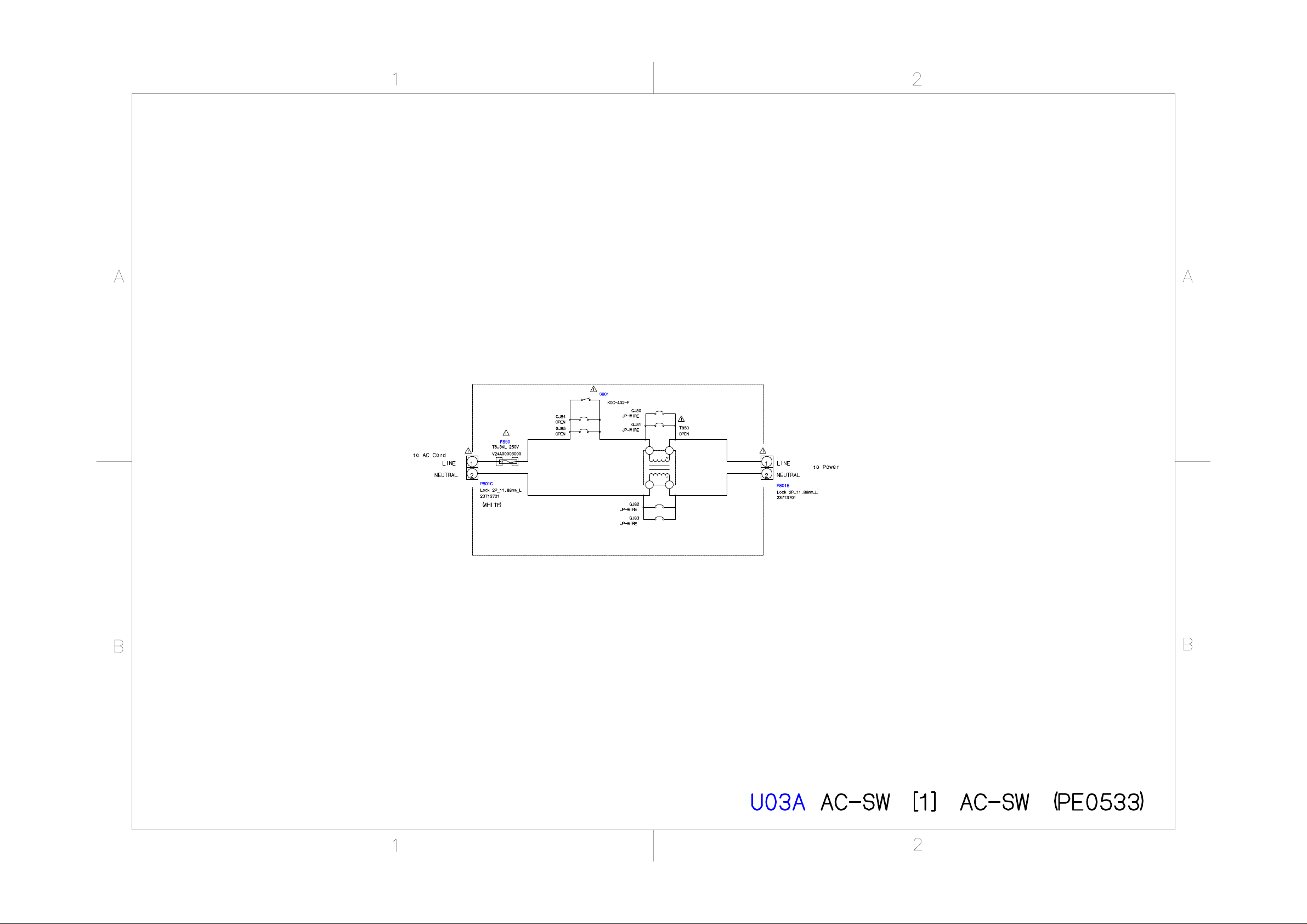
Page 76
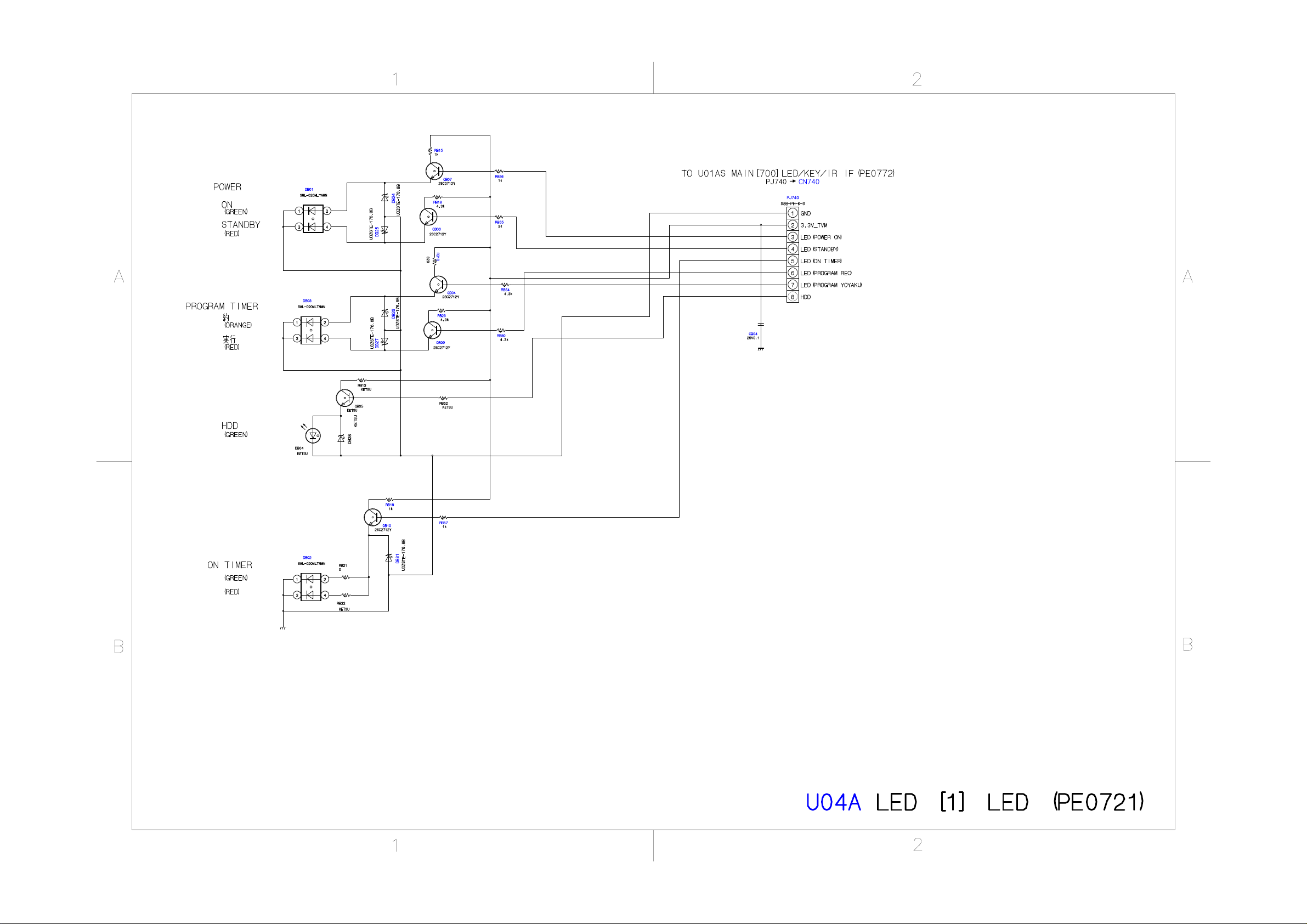
Page 77
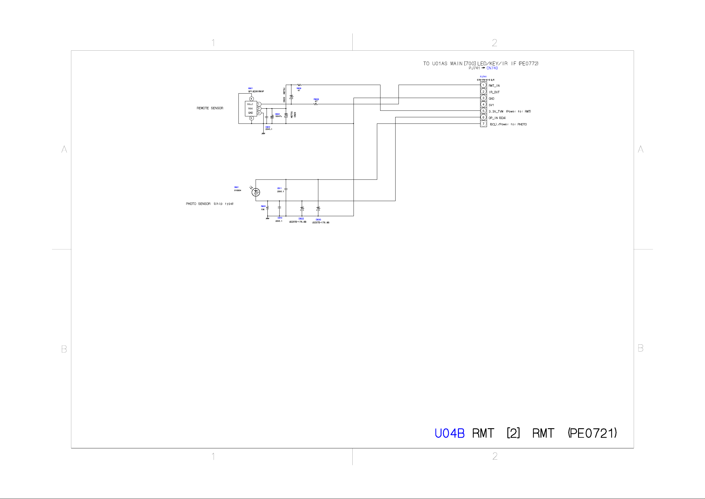
Page 78
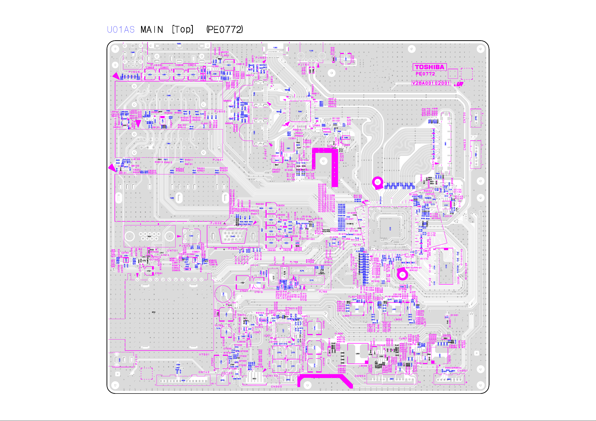
Page 79
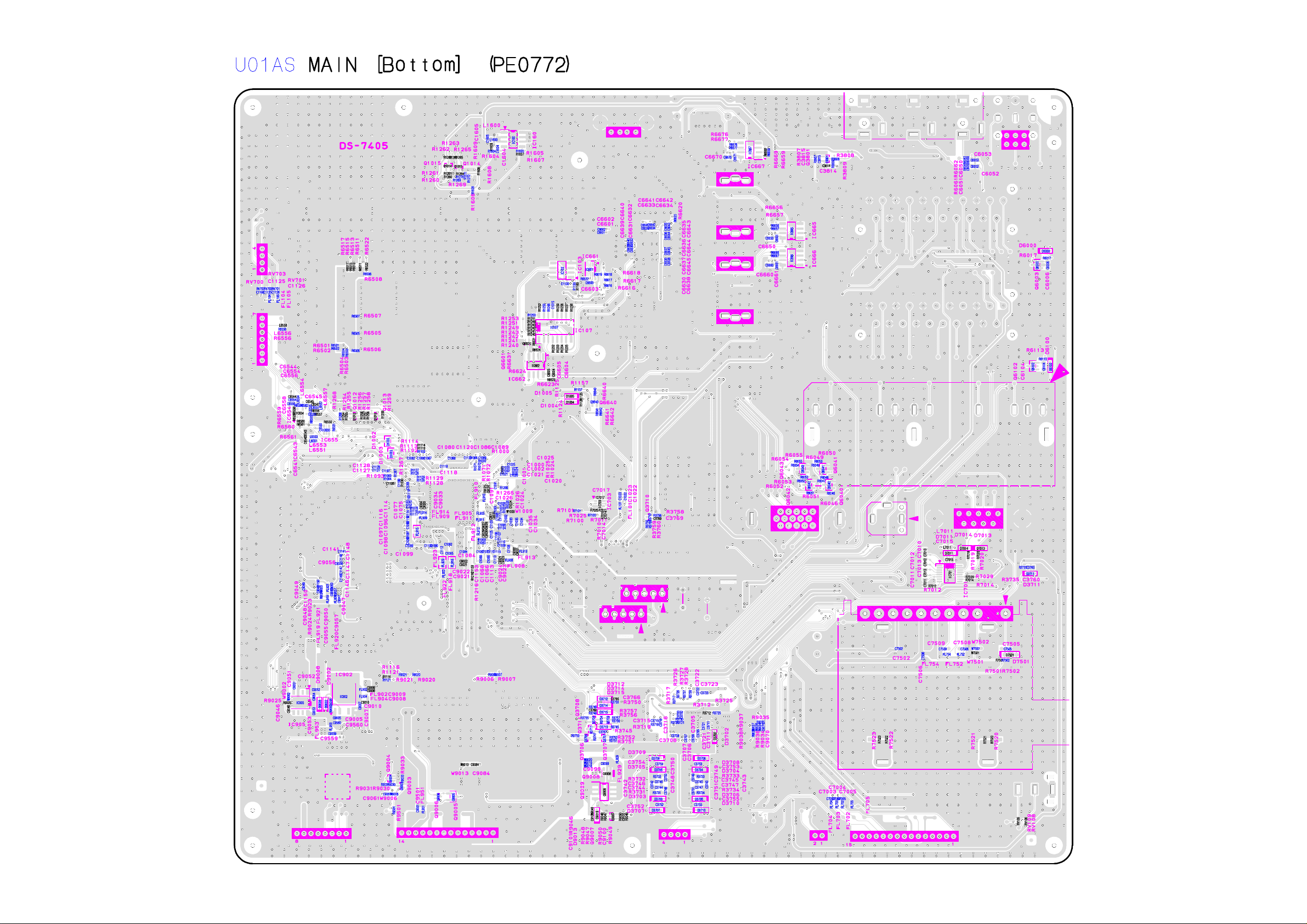
Page 80
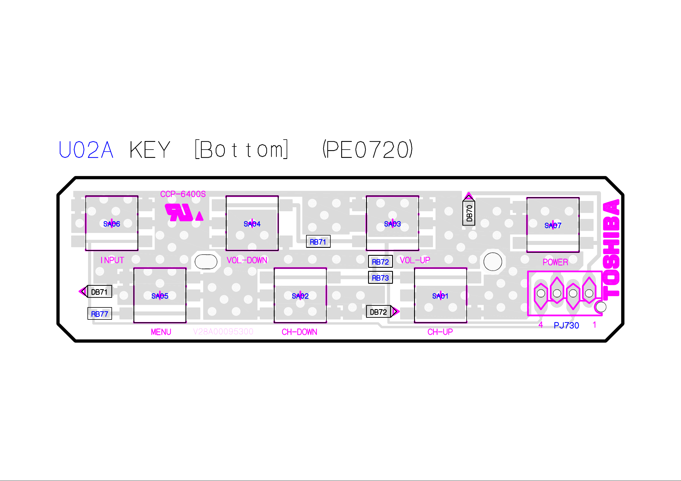
Page 81
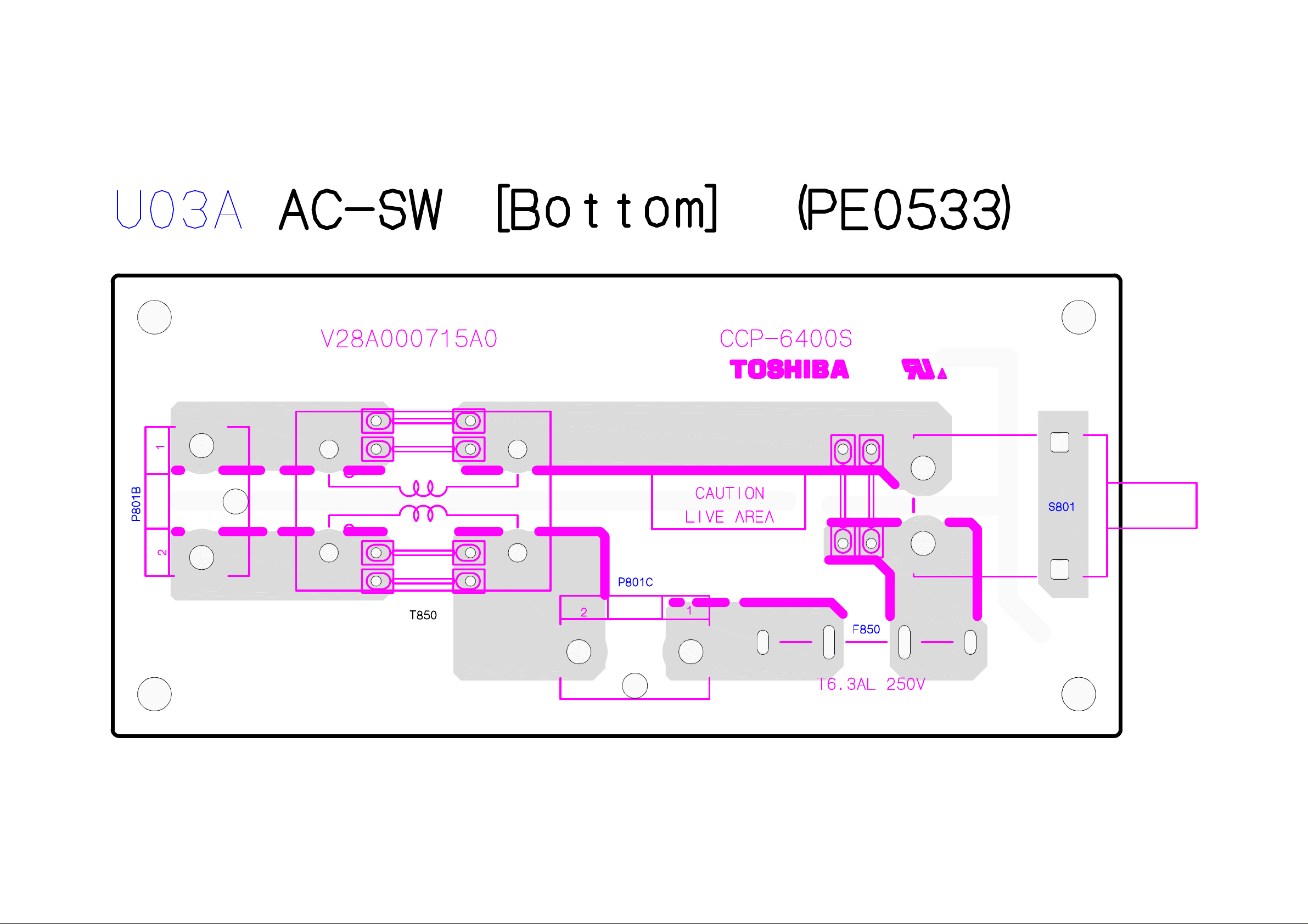
Page 82
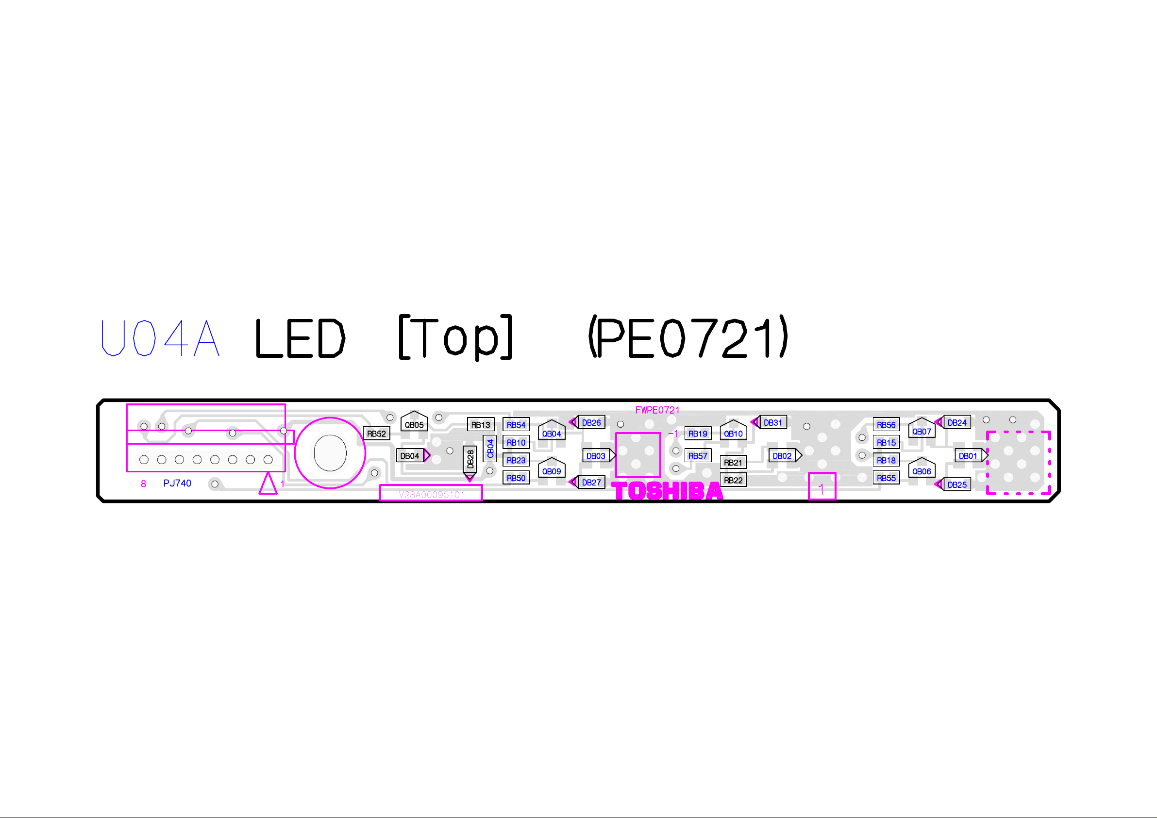
Page 83
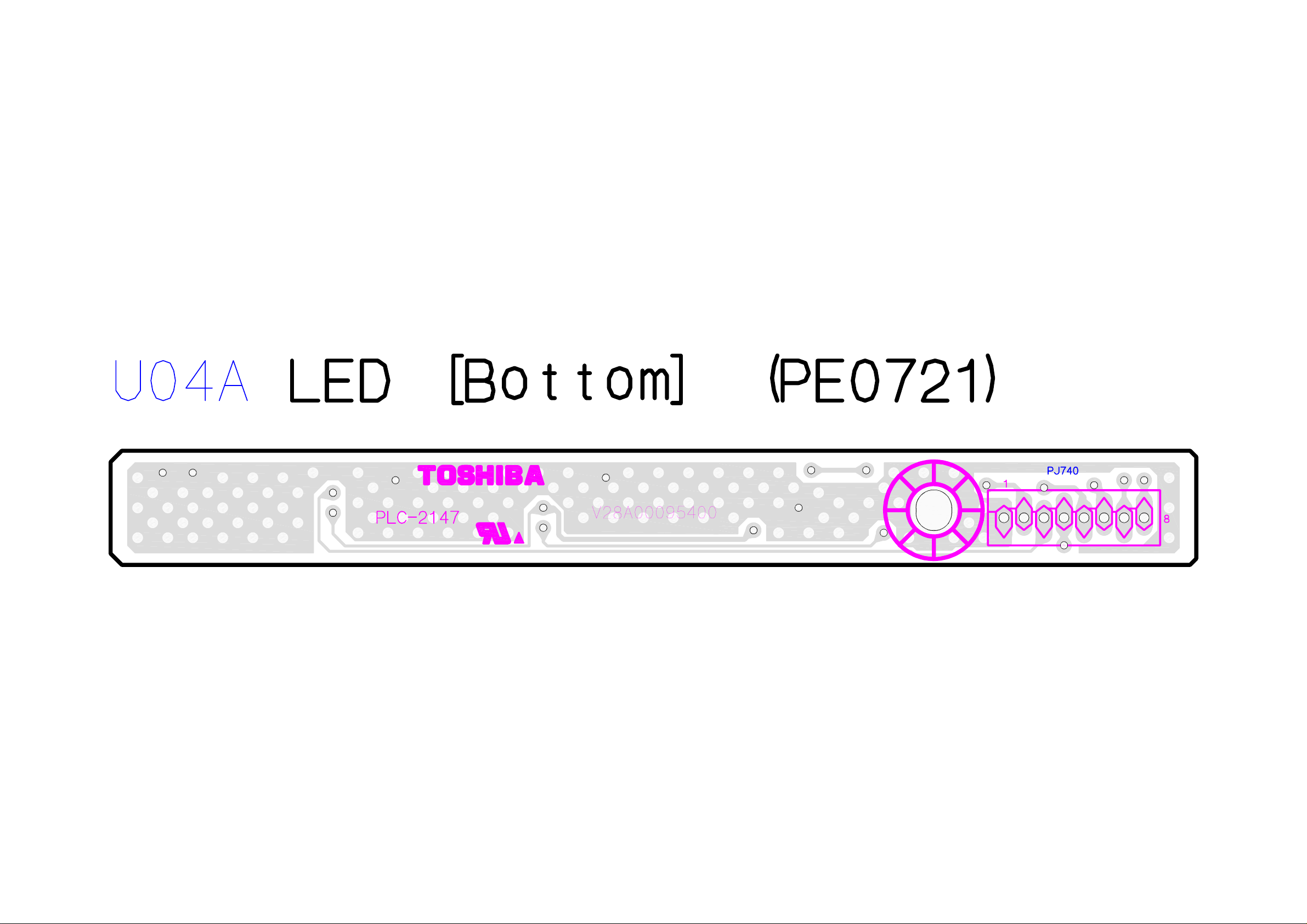
Page 84
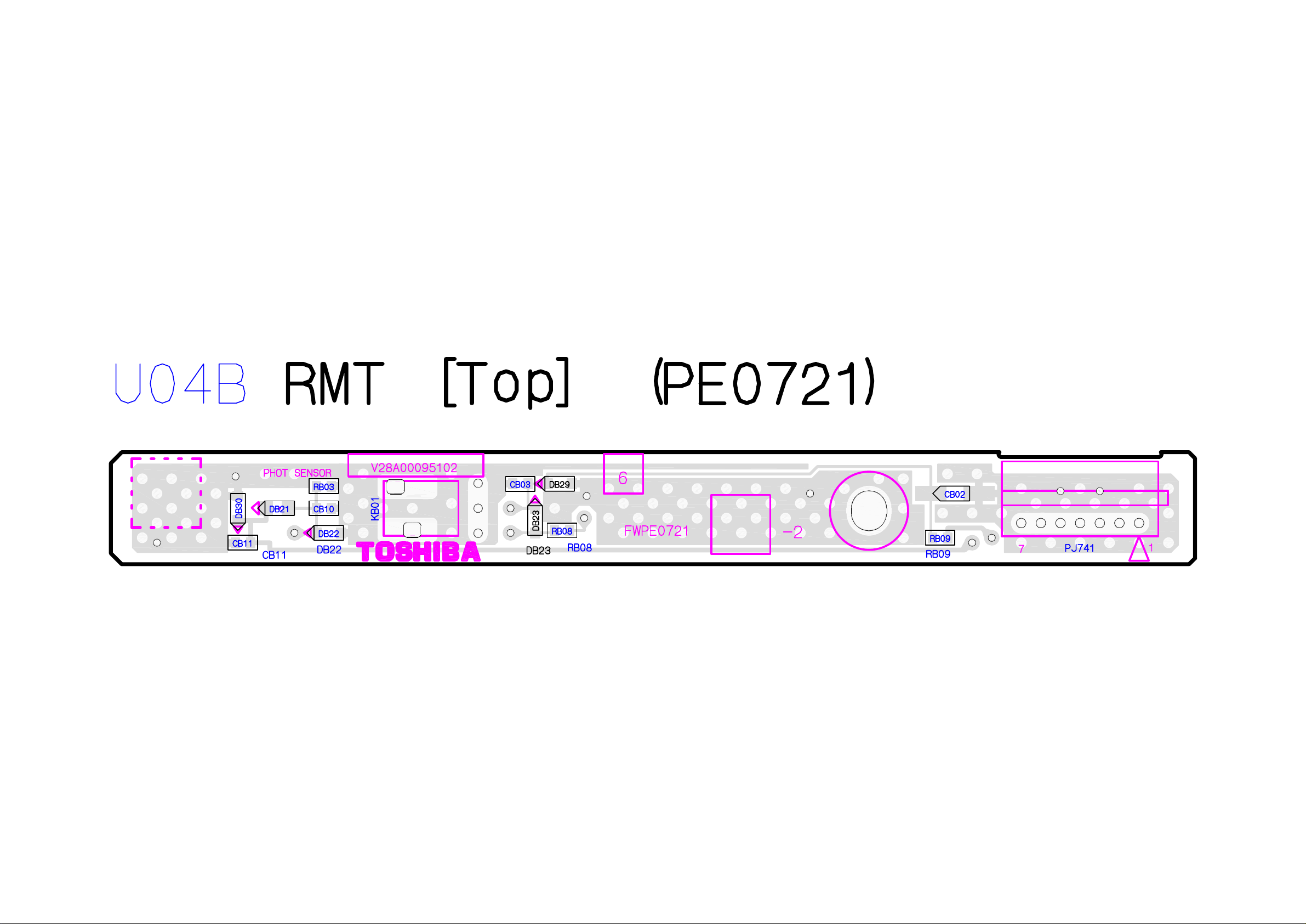
Page 85
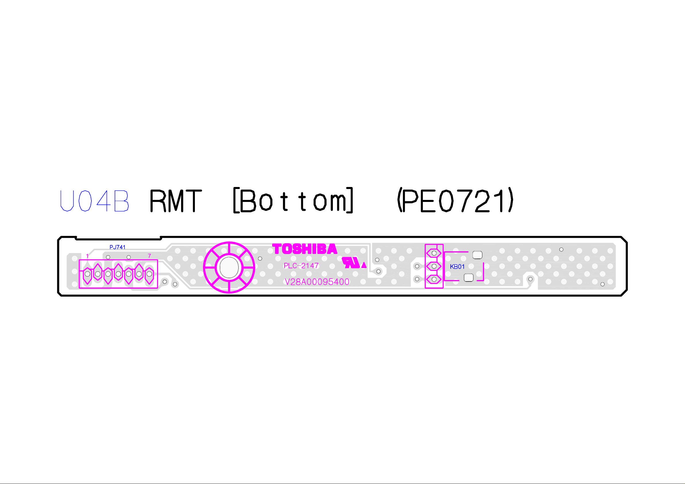
Page 86
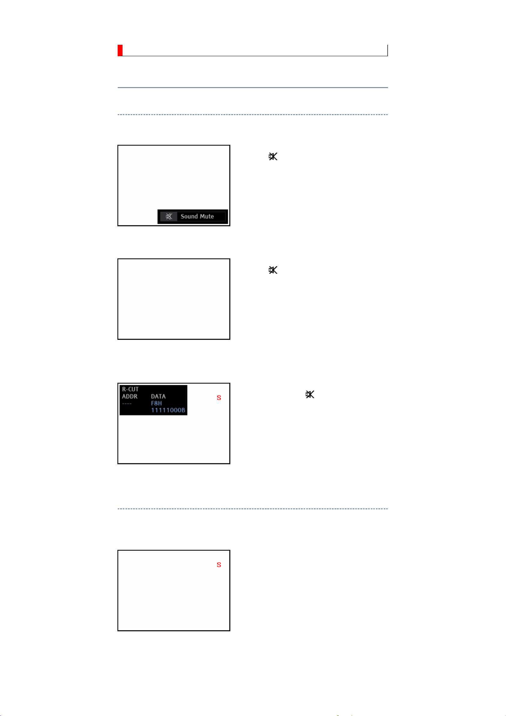
ADJUSTMENT
Service Mode
Entering to Service Mode
1. Press button once on remote control.
↓
↓
Service Mode display
2. Press button again and hold button down.
3. While holding the button, press MENU
button on TV set.
Displaying the Adjustment Menu
Press MENU button on TV.
Service Mode
Press ↑ ↓ Press
Adjustment Mode
Page 87
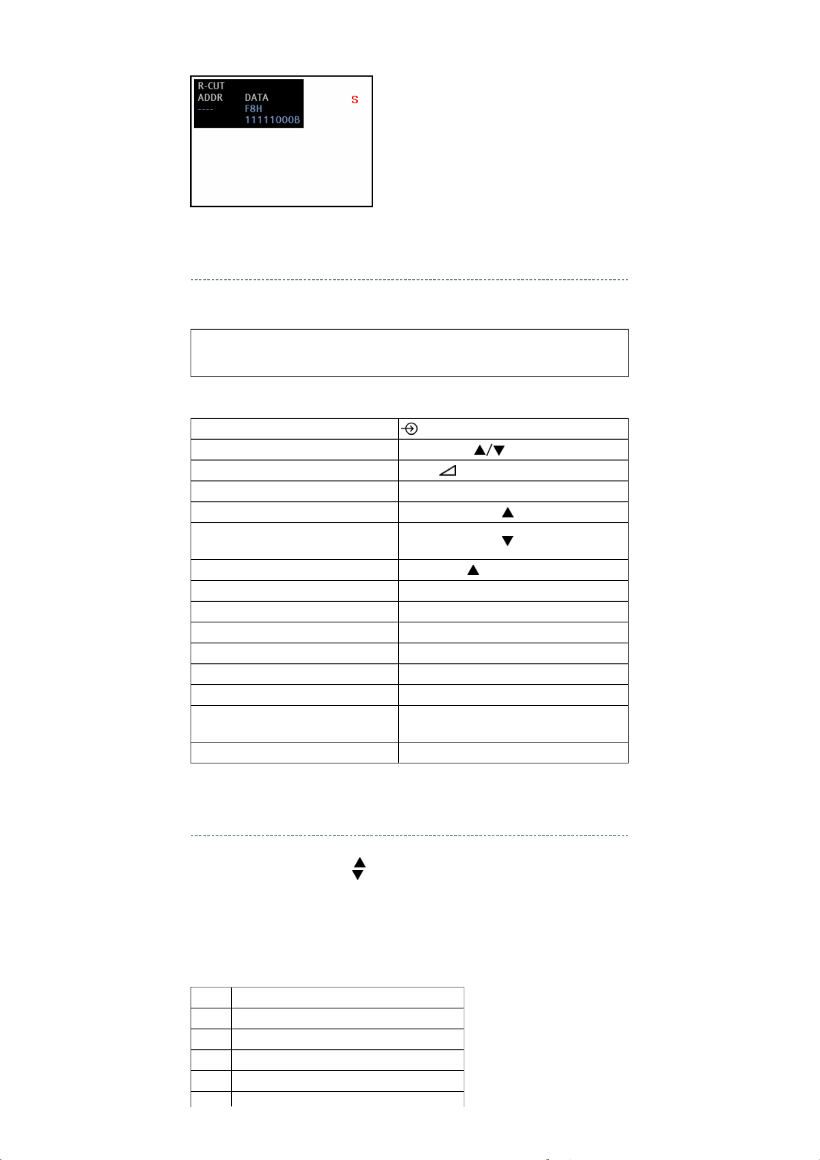
Key Function in the Service Mode
The following key entry during display of adjustment menu provides special functions.
CAUTION: Never try to perform initialization unless you have changed the
memory IC.
Test signal selection
Selection of the adjustment items
Change of the data value
Adjustment menu mode ON/OFF MENU button (on TV)
Initialization of the memory (IC510)
Reset the count of operating
protect circuit to "00"
Turn off TV Micro I2C bus communication
"RCUT" selection 1 button
"GCUT" selection 2 button
"BCUT" selection 3 button
"CNTX" selection 4 button
"COLC" selection 5 button
"UVTT" selection 6 button
button (on remote control)
PROGRAMME (on TV or remote control)
Volume +/- (on TV or remote control)
"i+" + PROGRAMME button on TV
"i+" + PROGRAMME button on TV
"i+" + Volume button on TV
Automatic A/D Adjustment
(PC, Component, Composite (PAL, NTSC))
Self diagnostic display ON/OFF 9 button
7 button
Selecting the Adjusting Item
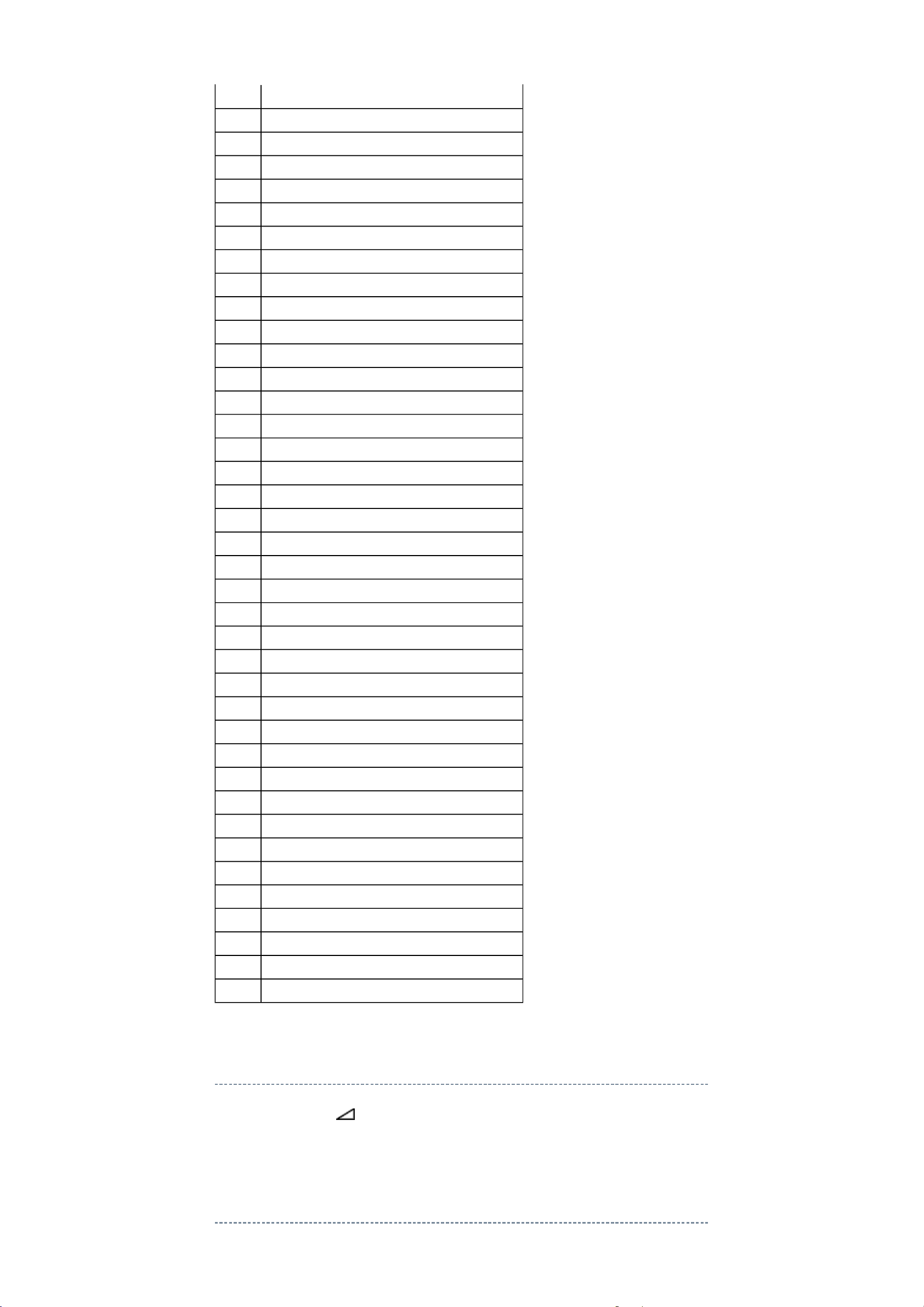
Every pressing of PROGRAMME button in the Service Mode changes the adjustment
items in the order of table below. ( button for reverse order)
SETTING & ADJUSTING DATA
[ SERVICE MODE ]
ADJUSTING ITEMS AND DATA IN THE SERVICE MODE:
Item Name of adjustment
CNTC CNTC
CNTN CNTN
BRTX BRTX
BRTN BRTN
Page 88
COLX COLX
COLN COLN
SHPX SHPX
SHPN SHPN
RCUT RCUT
GCUT GCUT
BCUT BCUT
RDRV RDRV
GDRV GDRV
BDRV BDRV
OSRC RCUT OFF SET COOL
OSGC GCUT OFF SET COOL
OSBC BCUT OFF SET COOL
OSRD RDRV OFF SET COOL
OSGD GDRV OFF SET COOL
OSBD BDRV OFF SET COOL
OSRC RCUT OFF SET NATURAL
OSGC GCUT OFF SET NATURAL
OSBC BCUT OFF SET NATURAL
OSRD RDRV OFF SET NATURAL
OSGD GDRV OFF SET NATURAL
OSBD BDRV OFF SET NATURAL
OSRC RCUT OFF SET WARM
OSGC GCUT OFF SET WARM
OSBC BCUT OFF SET WARM
OSRD RDRV OFF SET WARM
OSGD GDRV OFF SET WARM
OSBD BDRV OFF SET WARM
TVOP TV OPTION 0 (FUNCTION 1)
OPT1 TV OPTION 1 (FUNCTION 2)
OPT2 TV OPTION 2 (HOTEL OPT1)
OPT3 TV OPTION 3 (FUNCTION 3)
OPT4 TV OPTION 4
OPT5 TV OPTION 5
OPT6 TV OPTION 6 (HOTEL OPT2)
OPT7 TV OPTION 7 (HOTEL OPT3)
OPT8 TV OPTION 8 (HOTEL OPT4)
VOLUX Max limiter of Volume Control (for HOTEL mode)
Model SETID
Adjusting the Data
Pressing of VOLUME +/- button will change the value of data in the range from 00H to
FFH. The variable range depends on the adjusting item.
Setting TVOP
Page 89
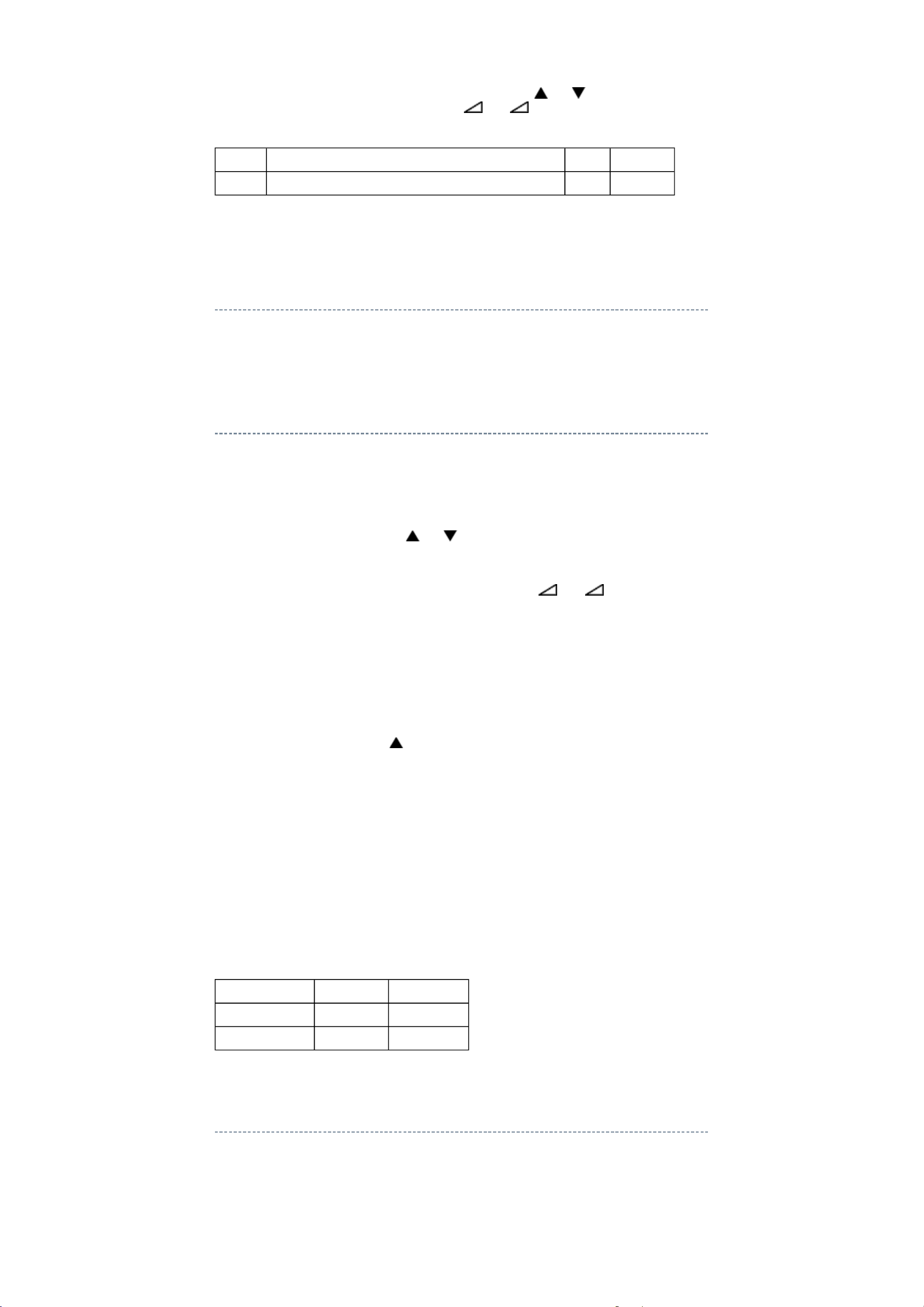
Enter Service Mode and select menu of TVOP by pressing P or P during display of
adjustment menu. After selecting TVOP, press + or - to set I2C check function to
disable or enable as below.
TVOP FUNCTION DESCRIPTION 1 0 (Normal)
D5 (bit5) I2C check between TV-Micro and Standby-Micro (WDT) Disable Enable
Exit from Service Mode
Pressing POWER button to turn off the TV once.
Initialization of TV Micro Data
After replacing Digital Board, the following initialization is required.
1) Enter the Service Mode.
2) Select menu of ID by pressing P or P during display of adjustment menu in the
Service Mode.
3) Change ID data into MODEL ID to initialize by pressing + or -, refer to
"MODEL ID TABLE".
For example, if initializing 40LV655P, change MODEL ID into "0x02".
Note:
MODEL ID is hex value.
4) Execute initialization of the memory.
Refer to "KEY FUNCTION IN THE SERVICE MODE".
Press "i+" + PROGRAMME button on TV.
5) Enter Service Mode and select Version Check Mode. Confirm if MODEL ID
corresponding to the model name is set correctly. If not, repeat the setteing..
Note:
In case initialization by setting wrong MODEL ID is done, there is a possibility of
abnormal display.
6) Check the picture carefully. If necessary, adjust any adjustment item above.
Perform "Auto tune" on the owner's manual.
MODEL ID TABLE
MODEL ID (HEX) Model name Panel vendor
0x01 32LV655P SAMSUNG
0x02 40LV655P SAMSUNG
Initializing Data setting flowchart after replacing the Signal Unit
Page 90
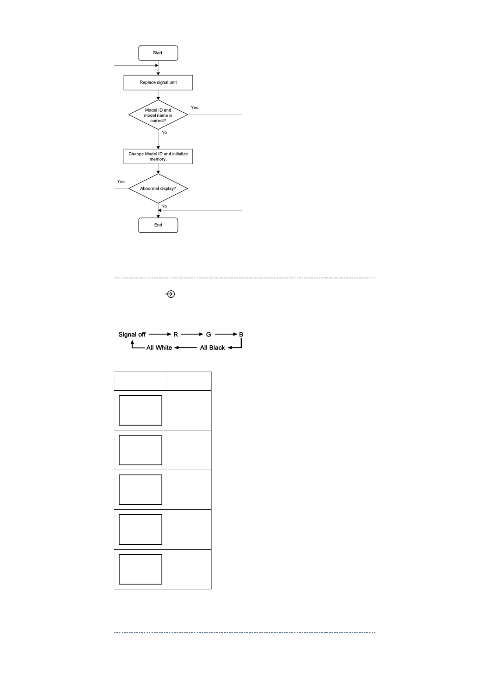
Test Signal Selection
Every pressing of button on the remote control changes the built-in test patterns on
screen as described below in Service Mode.
Picture Signal
Red raster
Green raster
Blue raster
All Black
All White
Self Diagnostic Function
1. Press "9" button on remote control during display of adjustment menu in the Service
Page 91
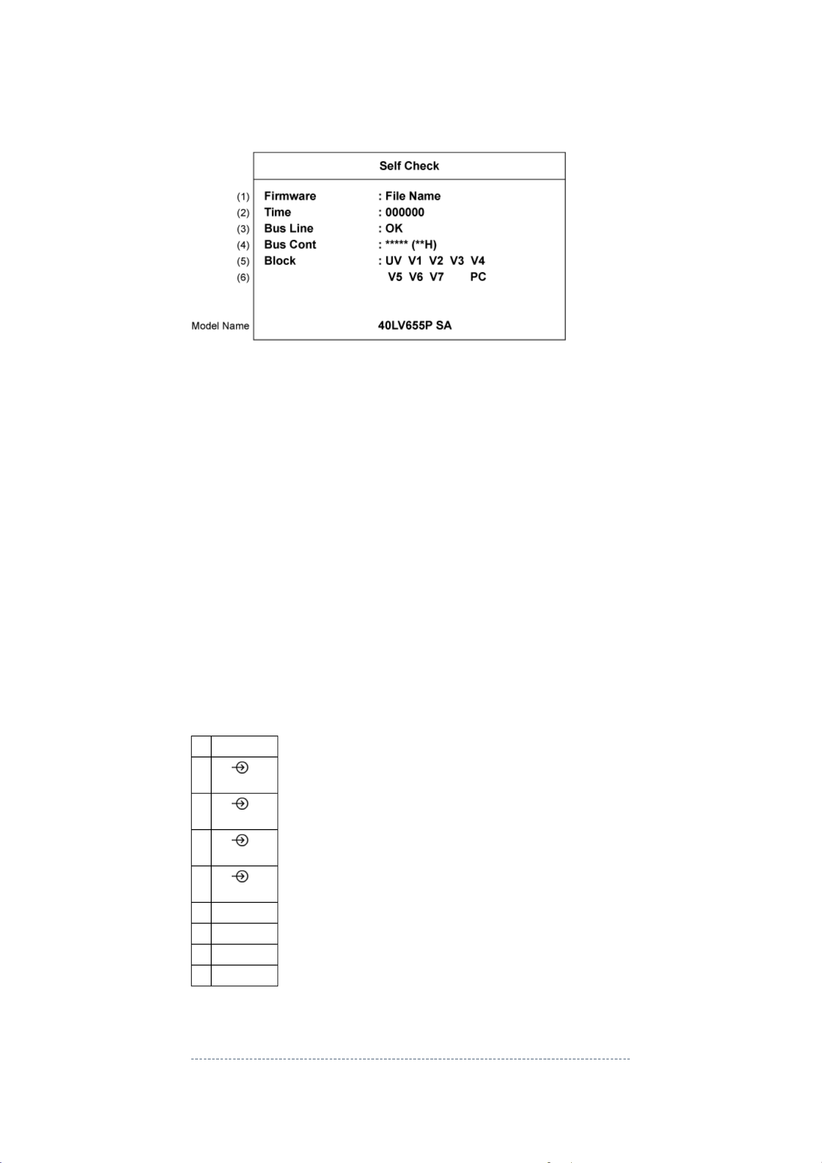
Mode. The diagnosis will begin to check if interface among IC's is executed properly.
7 input mode
2. During diagnosis, the following displays are shown.
* Self check displays and items are subject to the models.
(1) Firmware :
Display Target name and version information.
IF Target name: JH9_PJ, Version: 1.00 => "JH9_PJ 100"
(2) Time : Total time the TV has been turned on. (decimal, unit : H).
The time of Stand-by is not counted.
Min : 000000 max 999999 (unit hour)
(3) Bus line : "OK" is normal.
SCL-GND (Red indication) : SCL-GND short circuit
SDA-GND (Red indication) : SDA-GND short circuit
SCL-SDA (Red indication) : SCL-SDA short circuit
(4) Bus cont : "OK" is normal.
"NG" is abnormal (Red indication).
(5), (6) UV :TV reception mode
V1 - V7:VIDEO 1PC :PC input
Model name
Display Model name and panel vender
(Panel vendor --- SA : SAMSUNG AU : AUO SH : SHARP)
UV ATV
1
V1
V2
V3
V4
V5 HDMI1
V6 HDMI2
(Scart)
2
(Scart)
3
(Component)
4
(Composit)
V7 HDMI3
PC PC
Version Check Mode
1. Press "9" button twice on Remote Control during display of adjustment menu in the
Page 92
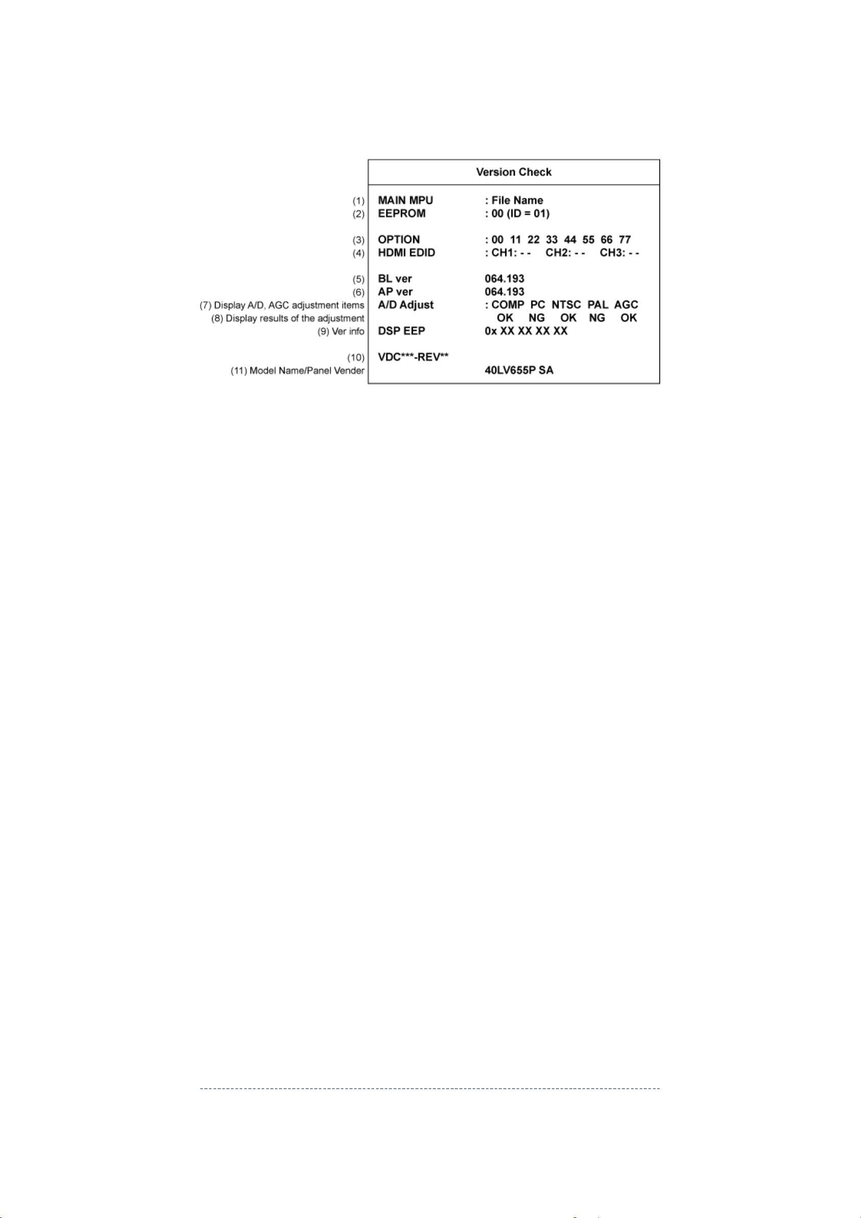
service mode.
COMP
NTSC (60 Hz) SD signal (composite input)
2. During Version Check, the following displays are shown.
* Version check displays and items are subject to the models.
(1) MAIN MPU :
Version information of microprocessor.
Series name and software program version (000_000).
(2) EEPROM :
Version information of Memory data in EEPROM : Display 1 byte data.
(3) OPTION :
Option information [Hex] : Display eight numbers of 1 byte data.
(4) HDMI EDID :
EDID data check item.
(Data is not shown)
(5) BL Ver :
Version information of Boot Loader software.
(6) AP Ver :
Version information of Application software.
(7)
A/D AGC Adjust :
A/D, AGC adjustment item.
-
- PC :PC input
- NTSC :
- PAL :PAL (50 Hz) SD signal (composite input)
- AGC :AGC adjustment
(8)
- OK :A/D, AGC adjusted correctly.
- NG :A/D, AGC adjusted incorrect.
(9) DSP EEP :
EEPROM information of DSP.
(10) Memory Data Version :
Version information of EEPROM.
VDC**** means model number of EEPROM.
REV** means version of EEPROM.
(11) Model name, panel vender :
Model name information (ASCII code). Display 8 byte data.
:Component input
Status Check Mode
1. Press "9" button thrice on Remote Control during display of adjustment menu in
Service Mode.
Page 93
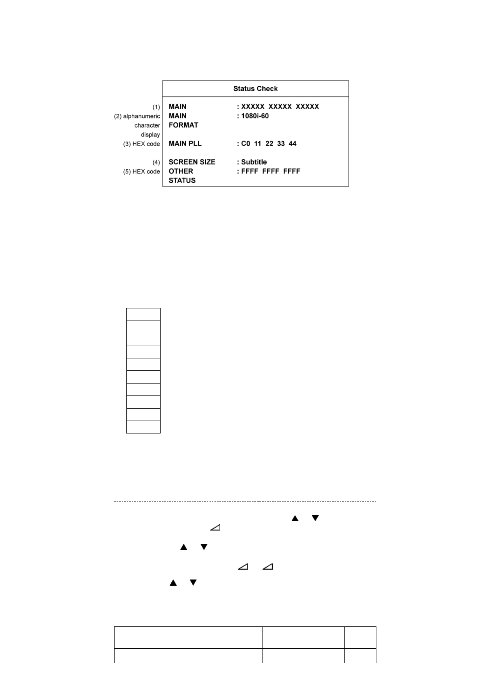
2. During Status Check, the following displays are shown.
* Status check displays and items are subject to the models.
(1) MAIN :
Main source information :
Display RF position number (0 - 999) on the main screen, or Input Source
(EXT1/2/3/HDMI etc.)
(2) MAIN FORMAT :
Display Video format information.
(3) MAIN PLL :
Main PLL information.
(4) SCREEN SIZE :
Display the screen size as follows.
Native
Subtitle
14:9
Wide
4:3
SuperLive
Cinema
PC Normal
PC Wide
Dot By Dot
(5) OTHER STATUS :
Other status information : Display three numbers of 2 byte data.
Setting Hotel Mode
Enter Service Mode and select Hotel Mode menu by pressing P or P .
After selecting Hotel Mode, press + to enter details setting in Hotel Mode.
To select menu, press P or P and press OK to enter the adjustment menu of following
table data.
To move the cursor in the adjustment, press + or -.
1. By pressing P or P , following table data setting will change the value either 1 or 0
on selected items as follows;
OPT2
OPT2 FUNCTION DESCRIPTION 1
D7 (bit7) Enable mode that TV standby will be Enable Disable
0
(Normal)
Page 94
appeared in forced when turning the
Mode and Super User mode
Enable mode that speaker volume will be set in
main power ON
(This function is ignored
when D6 is set to 1.)
D6 (bit6) Enable mode that TV On will be
appeared in forced when turning the
main power ON
D5 (bit5) FRONT Key Disable Enable
D4 (bit4) All keys except input selector key
(Video/TV)
D3 (bit3) User remote control operation Disable
D2 (bit2) Disable SET UP MENU except
language.
(tuning etc.)
D1 (bit1) Disable SETUP MENU Disable Enable
D0 (bit0) HOTEL Mode On (Enable the setting of
Enable Disable
Disable Enable
Enable
(Only setting of Service
are possible.)
Disable
(Display language only)
D1 to D7)
Enable
Off
(Normal)
VOLUX
Set speaker volume to suitable sound volume level.
VOLUX FUNCTION DESCRIPTION 1 0 (Normal)
D7 (bit7) ~
D0 (bit0)
Max Limiter of Volume Control 0x00 ~ 0x64
OPT6
OPT6 FUNCTION DESCRIPTION 1 0 (Normal)
D7 (bit7) Enable mode that POS or VIDEO program
number will be appeared in forced when
turning the main power ON
D6 (bit6) ~
D0 (bit0)
POS or VIDEO program number 0 ~ 127 [decimal] (Normal: 0)
Enable Disable
POS number: 0 ~ 99
VIDEO number: 100 ~ 127
(DTV = 100, VIDEO = 101,
VIDEO = 102..)
100 is used as ATV when
DTV option is disable.
OPT7
OPT7 FUNCTION DESCRIPTION 1 0 (Normal)
D7 (bit7)
D6 (bit6) ~
D0 (bit0)
forced when turning the main power ON
Forced speaker volume 0 ~ 100 [decimal] (Normal: 0)
Enable Disable
Value above 100 is no effect.
OPT8
OPT8 FUNCTION DESCRIPTION 1 0 (Normal)
D7 (bit7) ~
D4 (bit4)
D3 (bit3) RF tuning operation by position up/down on
remote or front panel of the TV set, number,
and previous key when HDMI or PC input
D2 (bit2) Enable mode that picture mode will be set in Enable Disable
No use - -
Disable Enable
Page 95
forced when turning the main power ON
D1 (bit1) ~
D0 (bit0)
Forced picture mode 0 [dec]: Dynamic
1 [dec]: Standard
2 [dec]: Mild
3 [dec]: Movie
LED Indications
The LEDs on the TV (at the bottom of the TV) indicate the TV's status, as described below.
Red ON (solid) and Green OFF = The TV power cord is plugged in, but TV is in
Standby.
Green ON (solid) = The TV is powered on.
LED Indication Condition Solution
1 Green LED turns OFF.
Red LED blinks
continuously at 0.5sec
period.
2 Green LED turns OFF.
Red LED blinks
continuously at 1.0sec
period.
BUS Error Turn OFF the TV and unplug the power
cord.
Plug the power cord in again and turn ON
the TV.
Power Protect
Error
Turn OFF the TV and unplug the power
cord.
Plug the power cord in again and turn ON
the TV.
Software Update
1. Extract the update files onto a USB drive.
2. Unplug the TV.
3. Connect the USB drive to the USB port on the side panel.
4. Plug in the TV and watch the Green LED on the front of the TV set.
Once the update started, the Green LED blinks continuously.
5. When the Green LED turned ON (solid), the update has completed successfully.
6. Unplug the TV set.
7. Disconnect the USB drive.
Page 96

TECHNICAL BULLETIN
File Name Title issuing date
Page 97

Page 98
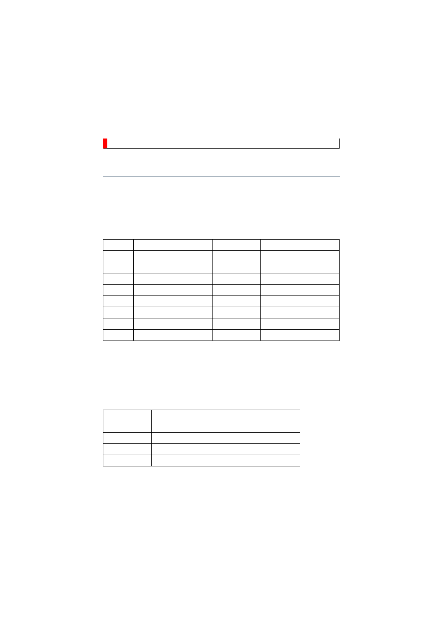
PANEL IDENTIFICATION
name, the identification marking will be shown at the last digit of the set serial number on the
Panel Identification
If the several panels are alternatively used in the same model without amending the model
specification label on the back cover.
In servicing, do not alter the panel because several setting and parts are different.
Marking Panel Vendor Marking Panel Vendor Marking Panel Vendor
A AUO J S SHARP
B K SAMSUNG T
C CMO L LGD U
D M V
E N W
F P X
G Q Y
H IPS R Z
With this alternative use, some of key parts may differ and their combinations are
indicated with the suffix marking on the location number in the part list
(Miscellaneous).
e.g.
Location No. Part No. Description
B001A 75XXXXXX LCD Panel, 32" LGD
B001B 75XXXXXX LCD Panel, 32" AUO
MZ01A 75XXXXXX LDVS Cable for 32" LGD Panel
MZ01B 75XXXXXX LDVS Cable for 32" AUO Panel
Please refer to the Parts List for correct part numbers.
Page 99
PARTS LIST
Capacitors
OMF
Precaution
WARNING: BEFORE SERVICING THIS CHASSIS, READ THE "SAFETY
PRECAUTION"
AND "PRODUCT SAFETY NOTICE".
CAUTION: The international hazard symbols " " in the schematic diagram
and the parts list designate components which have special characteristics
important for safety and should be replaced only with types identical to
those in the original circuit or specified in the parts list.
The mounting position of replacements is to be identical with originals.
Before replacing any of these components, read carefully the "SAFETY
PRECAUTION" and "PRODUCT SAFETY NOTICE".
Do not degrade the safety of the receiver through improper servicing.
Note:
The part number must be used when ordering parts, in order to assist in processing, be
sure to include the Model number and Description.
The PC board assembly with mark is no longer available after the end of the
production.
Abbreviations
CD : Ceramic Disk
Resistors CF : Carbon film
: Oxide Metal Film
PF : Plastic Film
CC : Carbon Composition
VR : Variable Resistor
EL : Electrolytic
MF : Metal Film
FR : Fusible Resistor
All CD and PF capacitors are ±5 %, 50 V and all resistor, ±5 %, 1/6 W unless otherwise
noted.
Page 100

PARTS LIST
↓
Select
Location :
Parts No. :
Search
Search
6
Page :
1 / 1
Jump
Jump
Block :
 Loading...