

Toshiba 32RV525RZ, 37RV52R, 37RV525RZ, 40RV52R, 40RV52RZ Service Material And Reference Tips
...
SMART2009-LCD209-V9 Page 1 of 10
S.M.A.R.T.
Service Material and Reference Tips
Product: LCD Date: 2/4/2010
Models: 32RV525RZ, 37RV52R, 37RV52RZ, 37RV525RZ, 40RV52R,
40RV52RZ, 40RV525R, 40RV525RZ, 46RV525R, 46RV525RZ
Doc Ref/File: SMART2009-LCD209-V9
Purpose: The purpose of this document is to give the service provider
troubleshooting information designed to expedite the diagnosis and service
process to modular/sectional level for Toshiba products.
[The information contained within the document will evolve over time so a version number has
been indicated in the document name. The servicer should always use the latest version
available.]
Table of Contents
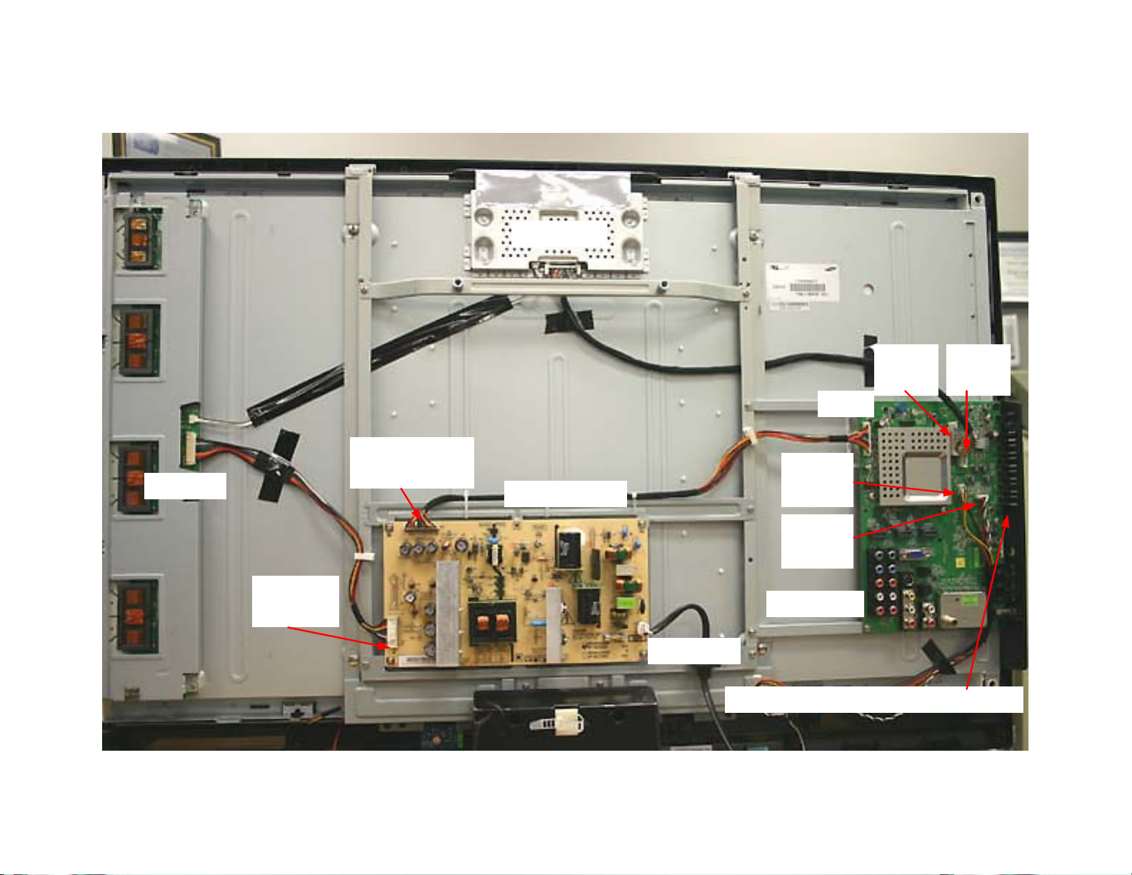
Section l Chassis Layout and Plug location
Section ll Modular Troubleshooting Flowcharts
Dead Set …………………………………………...4
Video Problems …………………....……….......5,6
Section lll Diagnostic Aids
Feedback: Please provide any comments or suggestions about this document
to technical_support@tacp.com
the document and version number on all correspondence.
Chassis and Plug Layout…....…………....…..….2
Interconnect…………………………….……….....3
Audio Problems …………………...………………7
Firmware Updates…………………………….…8,9
Factory Mode…………………………………..…10
When commenting, please provide
© 2009 Toshiba America Consumer Products, LLC.
32RV525RZ, 37RV52R, 37RV52RZ, 37RV525RZ, 40RV52R,
SMART2009-LCD209-V9 Page 2 of 10
40RV52RZ, 40RV525R, 40RV525RZ, 46RV525R, 46RV525RZ
T-CON
CN101
P803
Inverter
P802 Power
In/Out
Power PCB
P801 AC
CN3
LVDS
CN10
LVDS
CN8
CN5
IR/LED
CN2
Spkrs
Main PCB
Manual Switches and Front AV

32RV525RZ, 37RV52R,
SMART2009-LCD209-V9 Page 3 of 10
37RV52RZ, 37RV525RZ,
40RV52R, 40RV52RZ,
40RV525R, 40RV525RZ,
46RV525R, 46RV525RZ
Key
Pin 1
Flow >-out <-in
Power Supply In/Out
1. Gnd
2. Gnd
3. 24V Aud>
4. 24V Aud>
5. Gnd
6. Gnd
7. Gnd
8. 12V>
9. 12V(Panel Pwr.)>
10. 5V>**
11. 5V>**
12. 5V>**
13. Pwr. On (Enable) 4.0V<
14. AC Det.(PWR Good) .07V>
15. Dim 1.3 to 3.3V<
16. BL On 5V<
** Indicates Standby
C
N
8
J11
Test Plug
Pins 2, 4, 6, 8 –
12V Panel Power
LVDS
Power Supply In/Out
Manual switches
and side A/V
C
N
3
C
N
1
0
Some
Models
P
8
0
4
P
8
0
3
P802
Inverter
1. 24V<
2. 24V<
3. 24V<
4. 24V<
5. 24V<
6. Gnd
7. Gnd
8. Gnd
9. Gnd
10. Gnd
11. NC
12. BL On 5V<
13. Dim 1.3 to 3.3V<
14. NC
Power Supply
AC In
N
P801
L
LED/IR
1. 5V<**
2. IR>
3. GND
4. LED Logo
5. LED Green (Power)
Speakers
Main
C
N
5
CN2
 Loading...