

Toshiba 37HL86 Schematic
SERVICE MANUAL
(*1), as indicated by the underlined serial number.
Стр. 1 из
1
10.05.2015
file://C:\Documents and Settings\Alexsandr\Local Settings\Temp\Rar$EXa0.466\37H
...
LCD Color Television
37HL86
Ver. 1.01
This model is classified as a green product
This Service Manual describes replacement parts for the green product. When repairing this
green product, use the part(s) described in this manual and lead-free solder (*2).
For (*1) and (*2), refer to
SOLDER
© TOSHIBA CORPORATION
.
GREEN PRODUCT PROCUREMENT
and
LEAD-FREE

GREEN PRODUCT PROCUREMENT
Corporation recognizes environmental protection as a key management tasks, and is doing its
Стр. 1 из
1
10.05.2015
file://C:\Documents and Settings\Alexsandr\Local Settings\Temp\Rar$EXa0.381\37H
...
The EC is actively promoting the WEEE & RoHS Directives that define standards for
recycling and reuse of Waste Electrical and Electronic Equipment and for the Restriction of
the use of certain Hazardous Substances. From July 1, 2006, the RoHS Directive will
prohibit any marketing of new products containing the restricted substances.
Increasing attention is given to issues related to the global environmental. Toshiba
utmost to enhance and improve the quality and scope of its environmental activities. In line
with this, Toshiba proactively promotes Green Procurement, and seeks to purchase and use
products, parts and materials that have low environmental impacts.
Green procurement of parts is not only confined to manufacture. The same green parts used
in manufacture must also be used as replacement parts.

LEAD-FREE SOLDER
free solder must
free solder may result in damage to the component and or PCB being
Стр. 1 из
1
10.05.2015
file://C:\Documents and Settings\Alexsandr\Local Settings\Temp\Rar$EXa0.692\37H
...
This product is manufactured using lead-free solder as a part of a movement within the
consumer products industry at large to be environmentally responsible. Lead-
be used in the servicing and repair of this product.
WARNING: This product is manufactured using lead free solder.
DO NOT USE LEAD BASED SOLDER TO REPAIR THIS PRODUCT!
The melting temperature of lead-free solder is higher than that of leaded solder by 86ºF to
104ºF (30ºC to 40ºC). Use of a soldering iron designed for lead-based solders to repair
product made with lead-
soldered. Great care should be made to ensure high-quality soldering when servicing this
product especially when soldering large components, through-hole pins, and on PCBs as the
level of heat required to melt lead-free solder is high.
IMPORTANT NOTICE
Through WEB, ver. 6.5 has been released but with it, the linking function in this manual may
Стр. 1 из
2
10.05.2015
file://C:\Documents and Settings\Alexsandr\Local Settings\Temp\Rar$EXa0.953\37H
...
A Known Malfunction
Autodesk® DWF™ Viewer version
(Free software provided through WEB)
Use Autodesk DWF Viewer ver. 6.0.
not work properly.
If ver. 6.5 has been installed, uninstall it and reinstall ver. 6.0.
To get ver. 6.0, click the icon, or contact to the nearest Toshiba Service Centre for further
assistance.
Freezing windows opened
(Cannot close the open windows)
This may happen occasionally.
In case of encountering this, follow the procedure below.
1. Press [Ctrl], [Alt] and [Delete] keys at the same time to engage windows security
windows.
2. Then, choose TASK manager and Application tab, and select TOSHIBA SERVICE
MANUAL-Microsoft Internet Explorer.
3. Click TASK-end.
Main Window back forwarded
The real cause has not been found yet but with this condition, nothing disturbs the service
manual operation.

Continue to use by operating the windows.
Стр. 2 из
2
10.05.2015
file://C:\Documents and Settings\Alexsandr\Local Settings\Temp\Rar$EXa0.953\37H
...
Precaution when opening the diagrams
While opening the diagrams, the menu in the left frame changes its color to GRAY. This is
an indication that the viewer is processing.
With this condition, the menu indication color may stick to the GRAY color or Windows
may freeze if clicking other menu.
To avoid such things, do not operate any others while menu turns GRAY color.
If entering this, re-open the service manual or refresh the left frame.
IMPORTANT NOTICE
Стр. 1 из
4
10.05.2015
file://C:\Documents and Settings\Alexsandr\Local Settings\Temp\Rar$EXa0.117\37H
...
User Guide
Autodesk® DWF™ Viewer
this system. Please download and install.
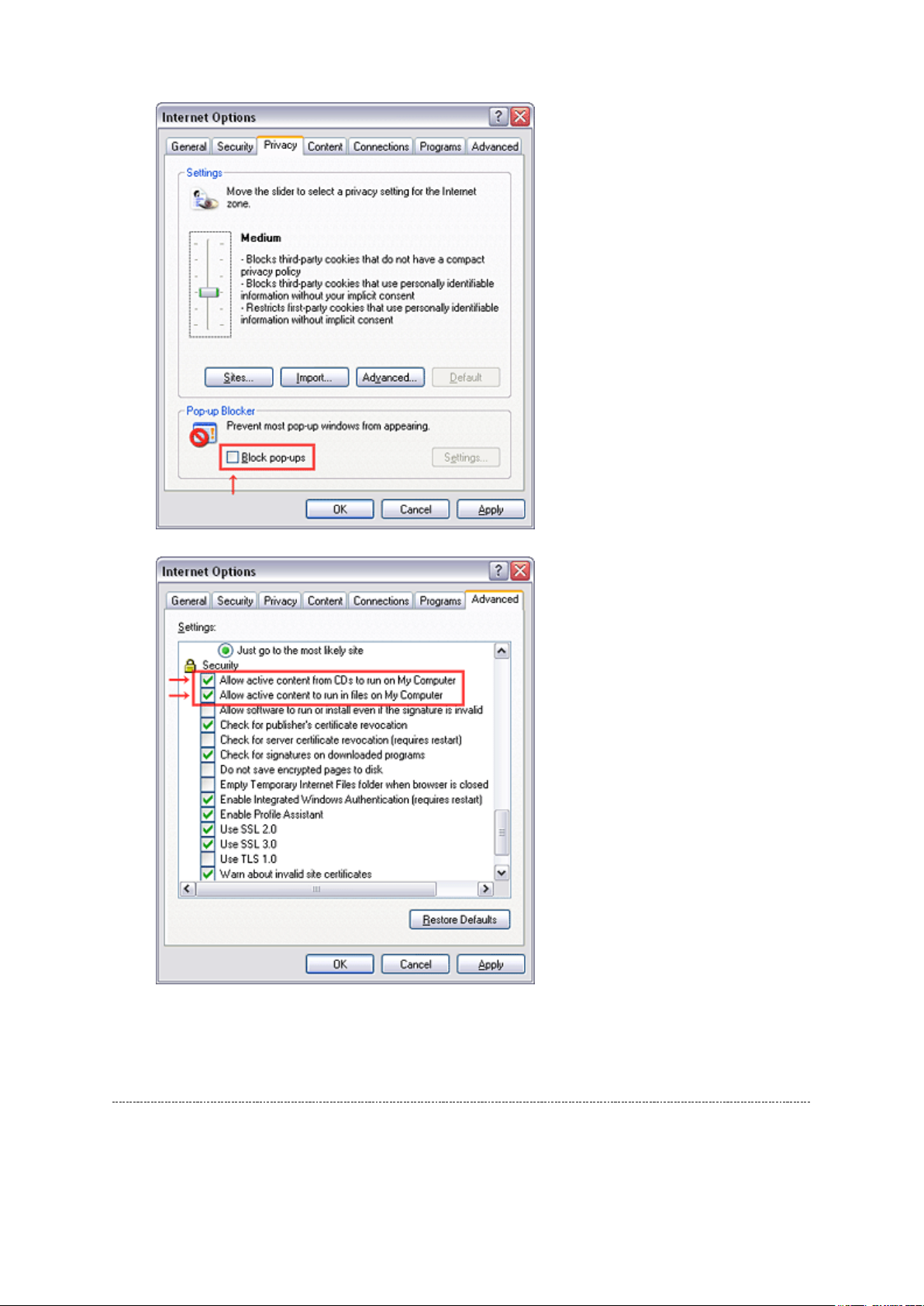
When
function and this sample may not work. In that case, perform the Internet Explorer setting
using the following procedure to restore normal operation.
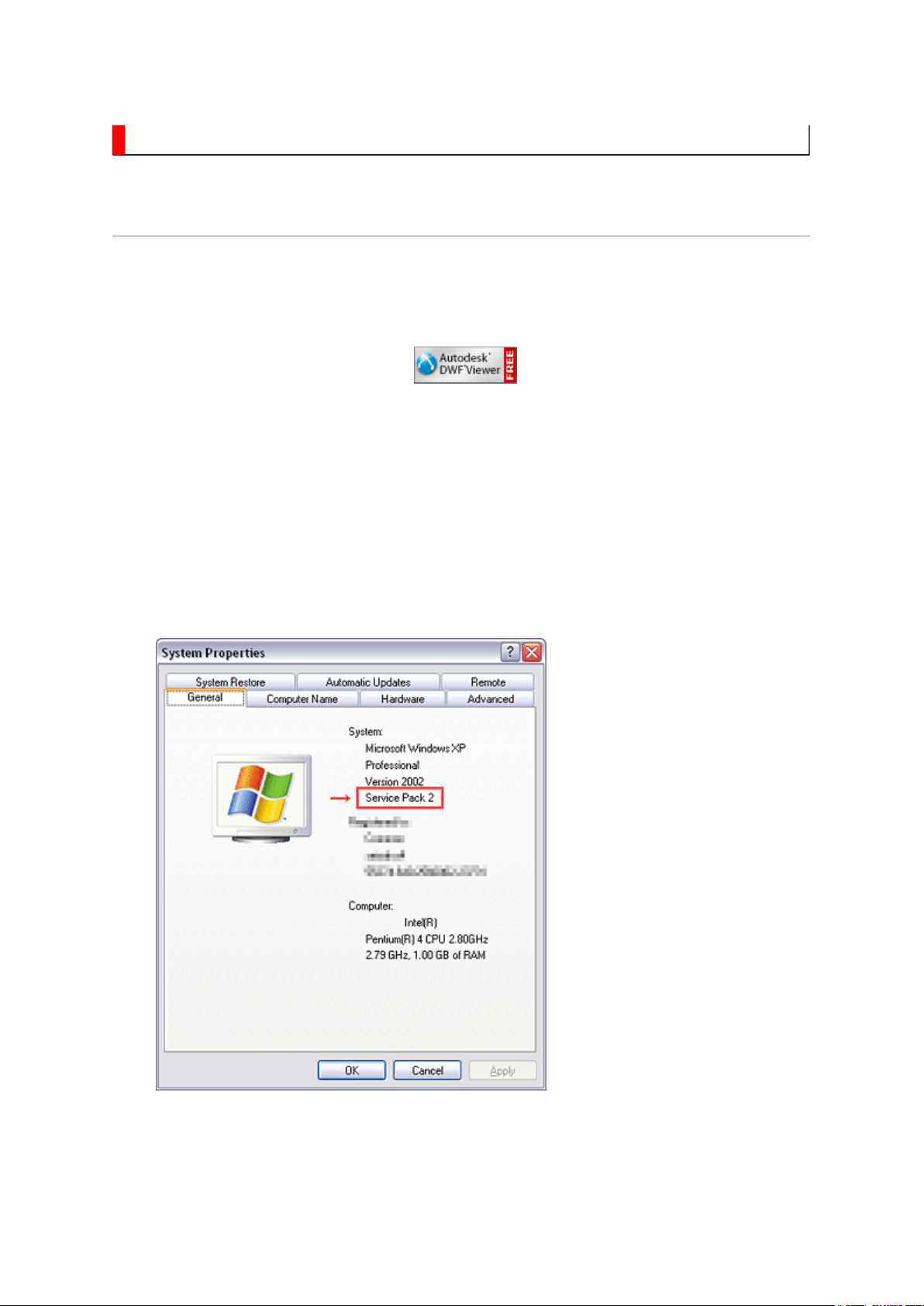
Windows XP SP2
1. Windows version check
[My Computer (right-click)] - [Properties]
is necessary to view drawings and to activate the functions of
is used, pop-up windows are limited by the enhanced security
2. Internet Explorer setting
[Tools] - [Internet Options]
Стр. 2 из
4
10.05.2015
file://C:\Documents and Settings\Alexsandr\Local Settings\Temp\Rar$EXa0.117\37H
...
Operating Environment
PC : Pentium III or higher recommended
Monitor : 1024 x 768 or higher resolution recommended

Mouse : A mouse with wheel recommended
Стр. 3 из
4
10.05.2015
file://C:\Documents and Settings\Alexsandr\Local Settings\Temp\Rar$EXa0.117\37H
...
OS : Microsoft Windows 2000/XP
Browser : Microsoft Internet Explorer 6.0 or later
Drawing viewer : Autodesk DWF Viewer 6.0
* Use the software following respective license terms and conditions.
Note:
In case of using this service manual with network connection, allocate its folder to the client
PCs as
network drive
to avoid any possible malfunction.
Or in case of accessing it through WEB site, the small pop-up window appears at the left
bottom corner on the screen whenever searching the location links. This is not malfunction.
Functions Provided on Each Drawing Page
Parts Information Reference Function
When the character string of a part on the drawing is clicked, its information is popped up at
the location. You can get any parts information immediately on the screen without referring
to the maintenance parts list.
Parts Search Function
You can search any part within the displayed drawing or within the whole schematic
diagram/board view by specifying a location number. The pop-up window displayed by
clicking a part's character string allows to search the part within the applicable schematic
diagram, board view or spare parts list.
A circle appears when the part is found, showing the part's location within the drawing.
Signal Line/Connector Destination Display Function
When a name at the end of a signal line in a divided schematic diagram is clicked, the
destination of the signal is searched and the display changes to the destination. Connecter
destinations can also be searched in the same way.
When two or more search results are provided, their drawing names are displayed, allowing
you to choose a desired drawing to display.

Layer Display Changing Function
When a pattern on a board view is clicked, it is highlighted in green. This allows easy pattern
Стр. 4 из
4
10.05.2015
file://C:\Documents and Settings\Alexsandr\Local Settings\Temp\Rar$EXa0.117\37H
...
When any of the color buttons on the toolbar is clicked, it can be selected to display desired
layer in its color or not to display each layer. This allows you to see the pattern layer only by
setting other layers to "non-display".
PC Board View Pattern Highlighting Function
tracing.
Specified Area Printing Function
The Autodesk DWF Viewer enables to print the displayed drawing region as it is on a
printer. It also allows to print a large-sized drawing in multiple pieces (tile printing).

IMPORTANT NOTICE
Стр. 1 из
1
10.05.2015
file://C:\Documents and Settings\Alexsandr\Local Settings\Temp\Rar$EXa0.419\37H
...
WARNING:
You are requested that you shall not modify or alter the information or data
provided herein without prior written consent by Toshiba. Toshiba shall not
be liable to anybody for any damages, losses, expenses or costs, if any,
incurred in connection with or as a result of such modification or alteration.
THE INFORMATION OR DATA HEREIN SHALL BE PROVIDED "AS IS"
WITHOUT ANY WARRANTY OF ANY KIND, EITHER EXPRESS OR IMPLIED
WARRANTY OF MERCHANTABILITY AND FITNESS FOR A PARTICULAR
PURPOSE.
Toshiba shall not be liable for any damages, losses, expenses or costs, if
any, incurred in connection with or as a result of use of any information or
data provided herein.
ADJUSTMENT
Стр. 1 из
11
10.05.2015
file://C:\Documents and Settings\Alexsandr\Local Settings\Temp\Rar$EXa0.213\37H
...
Service Mode
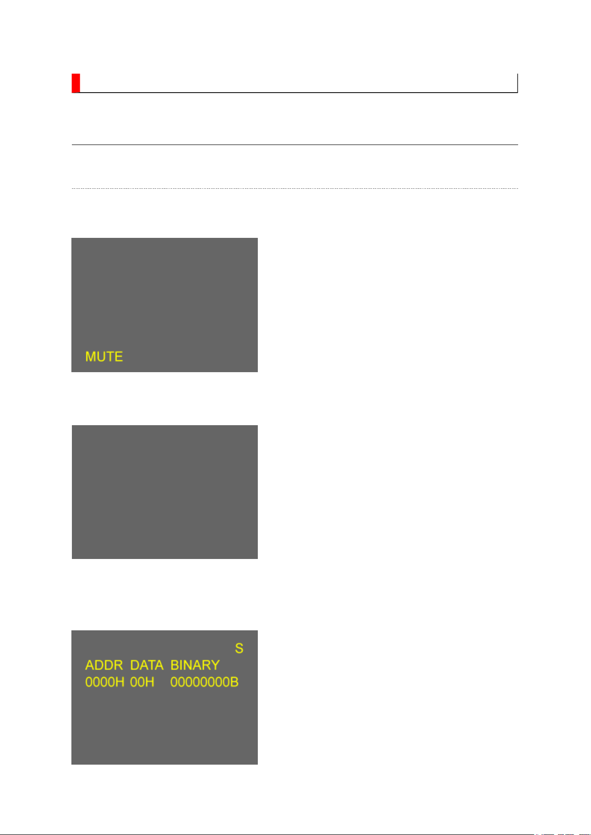
Entering to Service Mode
1. Press MUTE button once on remote control.
↓↓↓↓
↓↓↓↓
Service Mode display
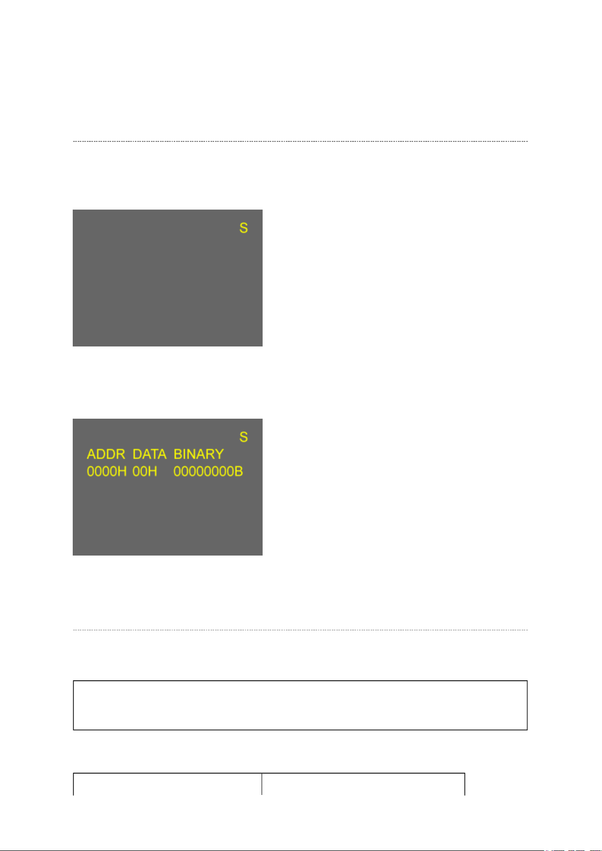
2. Press MUTE button again and keep pressing.
3. While pressing the MUTE button, press
MENU button on TV set.
Стр. 2 из
11
10.05.2015
file://C:\Documents and Settings\Alexsandr\Local Settings\Temp\Rar$EXa0.213\37H
...
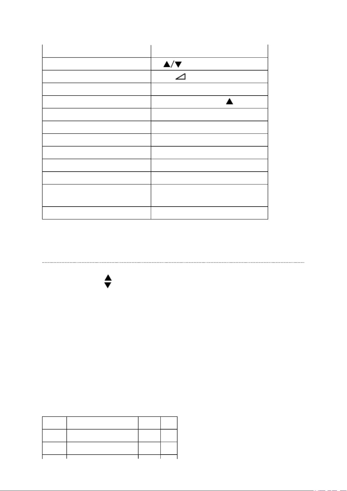
Displaying the Adjustment Menu
Press MENU button on TV.
Service Mode
Press
Adjustment Mode
↑↑↑↑ ↓↓↓↓
Press
Key Function in the Service Mode
The following key entry during display of adjustment menu provides special functions.
CAUTION: Never try to perform initialization unless you have changed the
memory IC.
Test signal selection INPUT button (on remote control)
Стр. 3 из
11
10.05.2015
file://C:\Documents and Settings\Alexsandr\Local Settings\Temp\Rar$EXa0.213\37H
...
Selection of the adjustment items CH (on TV or remote control)
Change of the data value Volume +/- (on TV or remote control)
Adjustment menu mode ON/OFF MENU button (on TV)
Initialization of the memory (QA02) CALL + CH button on TV ( )
"RCUT" selection 1 button
"GCUT" selection 2 button
"BCUT" selection 3 button
"CNTX" selection 4 button
"COLC" selection 5 button
"UVTT" selection 6 button
Automatic A/D Adjustment
(PC, Component, Composite (NTSC))
Self diagnostic display ON/OFF 9 button
7 button
Selecting the Adjusting Item
Every pressing of CH button in the service mode changes the adjustment items in the
order of table below. ( button for reverse order)
SETTING & ADJUSTING DATA
[ SERVICE MODE ]
ADJUSTING ITEMS AND DATA IN THE SERVICE MODE:
Note:
The image system data of RCUT-BDRV is different by each image format.
Item Name of adjustment Preset Data
RCUT R CUT OFF 00H
GCUT G CUT OFF 00H
←
←
BCUT B CUT OFF 00H
Стр. 4 из
11
10.05.2015
file://C:\Documents and Settings\Alexsandr\Local Settings\Temp\Rar$EXa0.213\37H
...
←
RDRV R DRIVE 7EH
GDRV G DRIVE 80H
BDRV B DRIVE 8BH
BRTC BRIGHTNESS CENTER FEH
COLC COLOR CENTER B8H
UVTT BASE BAND TINT FEH
CNTX CONTRAST MAX 86H
VOLUX MAX VOLUME LIMITED 7FH
PLLW0 PLL WAIT TIME 14H
PLLW1 PLL WAIT TIME 03H
PLLW2 PLL WAIT TIME 0FH
PLLW3 PLL WAIT TIME 05H
PLLW4 PLL WAIT TIME 14H
PLLW5 PLL WAIT TIME 04H
←
←
←
←
←
←
←
←
←
←
←
←
←
←
Adjusting the Data
Pressing of VOLUME +/- button will change the value of data in the range from 00H to
FFH. The variable range depends on the adjusting item.
Exit from Service Mode
Pressing POWER button to turn off the TV once.
Initialization of Memory Data of QA02
After replacing QA02, the following initialization is required.
CAUTION: Never attempt to initialize the data unless QA02 has been
replaced.
1. Enter the service mode, then select any register item.
Стр. 5 из
11
10.05.2015
file://C:\Documents and Settings\Alexsandr\Local Settings\Temp\Rar$EXa0.213\37H
...
2. Press and hold the CALL button on the remote control, then press the CH button on
the TV.
The initialization of QA02 has been completed.
3. Check the picture carefully. If necessary, adjust any adjustment item above.
Perform "Auto tune" on the owner's manual.
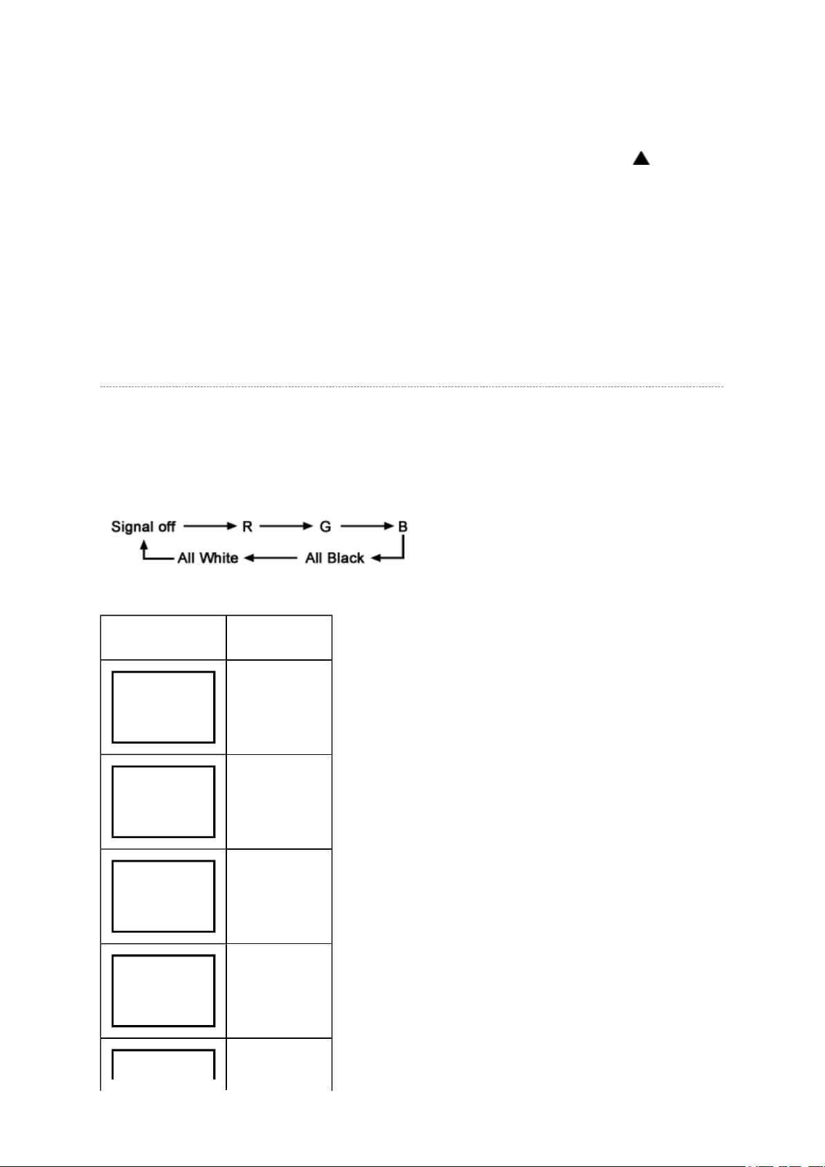
Test Signal Selection
Every pressing of INPUT button on the remote control changes the built-in test patterns on
screen as described below in Service Mode.
Picture Signal
Red raster
Green raster
Blue raster
All Black
NG is abnormal (Red indication).
Стр. 6 из
11
10.05.2015
file://C:\Documents and Settings\Alexsandr\Local Settings\Temp\Rar$EXa0.213\37H
...
All White
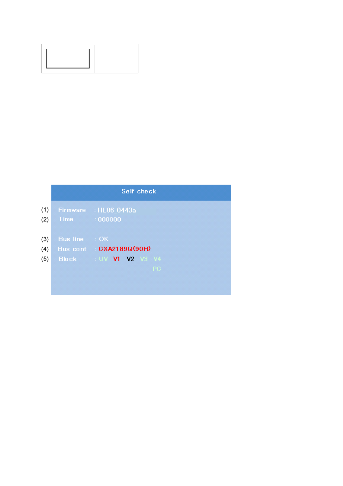
Self Diagnostic Function
1. Press "9" button on remote control during display of adjustment menu in the service
mode. The diagnosis will begin to check if interface among IC's is executed properly.
2. During diagnosis, the following displays are shown.
(1) Firmware :
Version information of microprocessor
In case of file name : HL86 and Version : 0443a indicates [HL86_0443a].
(2) Time : Total hour of turn the TV on. (Unit : H)
(3) Bus line : -- "OK" is normal
SCL-GND (Red indication) : SCL-GND short circuit
SDA-GND (Red indication) : SDA-GND short circuit
SCL-SDA (Red indication) : SCL-SDA short circuit
(4) Bus cont : --- "OK" is normal.
When type name of semiconductor indicates.
(5) Block
Стр. 7 из
11
10.05.2015
file://C:\Documents and Settings\Alexsandr\Local Settings\Temp\Rar$EXa0.213\37H
...
UV : TV reception mode
V1 - V4 : VIDEO 1-4 input mode
PC : PC mode
UV RF
V1
(Composite/Component)
V2
(Composite/S-VIDEO)
V3
V4 HDMI
PC PC
HL86
Video1
ColorStreamHD1
Video2
ColorStreamHD2
(Component)
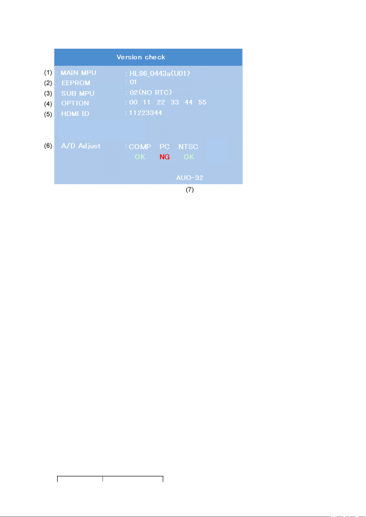
Version Check Mode
1. Press "9" button twice on remote control during display of adjustment menu in the
service mode.
The version of main MPU will begin to check.
2. During Version Check, the following displays are shown.
NTSC (60 Hz) SD signal (composite input)
Стр. 8 из
11
10.05.2015
file://C:\Documents and Settings\Alexsandr\Local Settings\Temp\Rar$EXa0.213\37H
...
(1) MAIN MPU :
Version information of microprocessor
In case of file name : HL86, Version 0443a for Code Program Version and (U01) for
OSD Version indicates [HL86_0443a (U01)]
(2) EEPROM :
Version information of EEPROM : Display 1 byte data.
(3) SUB MPU :
Version information of SUB MPU : Display 1 byte data.
(4) OPTION :
Option information : Display six numbers of 1 byte data.
(5) HDMI ID :
HDMI ID information : Display 4 byte data.
(6) A/D Adjust
A/D adjustment item.
--COMP : Component input
--PC : PC input
--NTSC :
--OK : A/D adjustment set correctly.
--NG : A/D adjustment set incorrect.
(7) LCD Panel Vender information display
The following Panel Vender and screen size are displayed.
Panel Vender Screen Size (Inch)
Стр. 9 из
11
10.05.2015
file://C:\Documents and Settings\Alexsandr\Local Settings\Temp\Rar$EXa0.213\37H
...
LPL -26
SHP -32
CMO -37
AUO
Example : AUO-32 indicates that Vender is AUO and Screen Size is 32 inch.
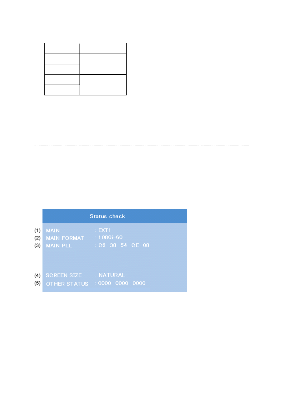
Status Check Mode
1. Press "9" button thrice on remote control during display of adjustment menu in the
service mode.
The status of this model will begin to check.
2. During Status Check, the following displays are shown.
(1) MAIN :
Main source information :
Display RF position number (1 - 125) on the main screen, or Input Source
(EXT1/2/3/HDMI etc.)
(2) MAIN FORMAT :
Display Video and PC format information
(3) MAIN PLL :
Стр. 10 из
11
10.05.2015
file://C:\Documents and Settings\Alexsandr\Local Settings\Temp\Rar$EXa0.213\37H
...
Main PLL information : Display 1 byte data at five.
(4) SCREEN SIZE :
Display the one of screen size as follows.
Theater Wide 1
Theater Wide 2
Theater Wide 3
FULL
NATURAL
4:3 HD
(5) OTHER STATUS :
Other status information : Display three numbers of 2 byte data.
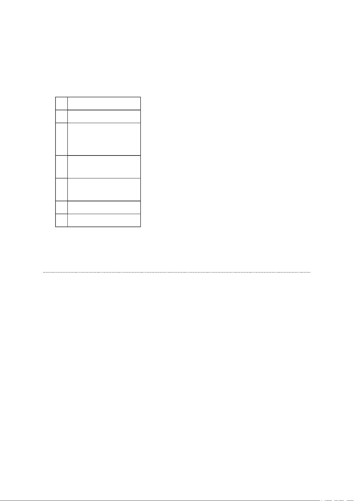
LED Indication
The Red LEDs on the TV (at the bottom center of the TV) indicate the TV's status, as
described below.
Red OFF = The TV is in a standby state.
Red ON = The TV is in a normal operation state.
1 Red blinks continuously at 0.5-
second intervals.
2 Red blinks continuously at 1-
second intervals.
LED Indication Condition Solution
Abnormal operation Turn OFF the TV and unplug
the power cord.
Plug the power cord in again
and turn ON the TV.
Abnormal operation of
BUS line.
Turn OFF the TV and unplug
the power cord.
Plug the power cord in again
and turn ON the TV.

Стр. 11 из
11
10.05.2015
file://C:\Documents and Settings\Alexsandr\Local Settings\Temp\Rar$EXa0.213\37H
...
FUNCTION AND OPERATION
Стр. 1 из
2
10.05.2015
file://C:\Documents and Settings\Alexsandr\Local Settings\Temp\Rar$EXa0.268\37H
...
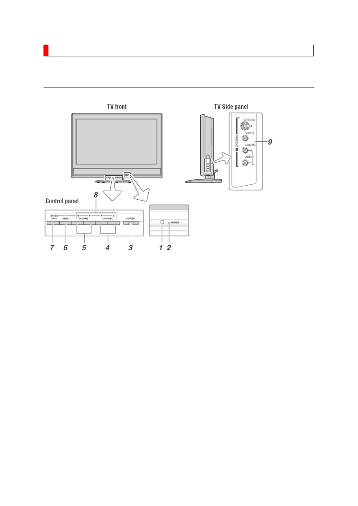
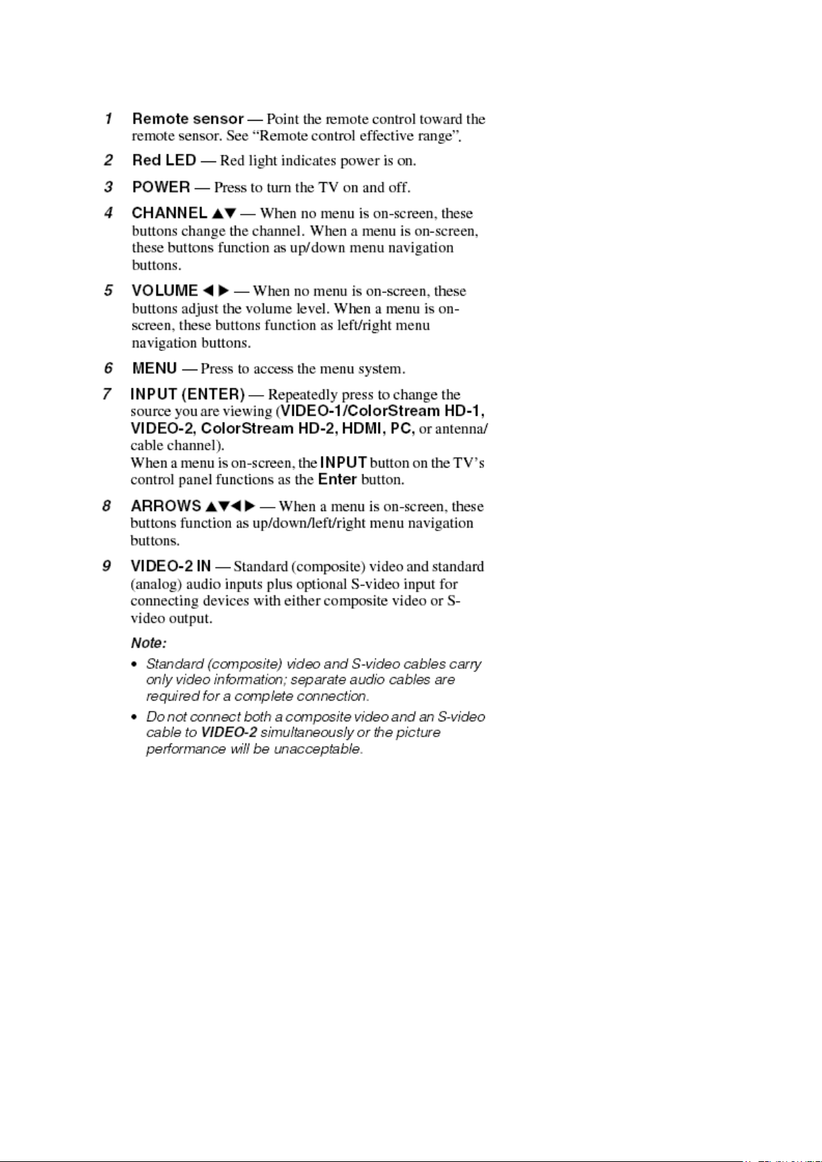
TV Front and Side Panel Control and Connection
Стр. 2 из
2
10.05.2015
file://C:\Documents and Settings\Alexsandr\Local Settings\Temp\Rar$EXa0.268\37H
...

FUNCTION AND OPERATION
Стр. 1 из
3
10.05.2015
file://C:\Documents and Settings\Alexsandr\Local Settings\Temp\Rar$EXa0.433\37H
...
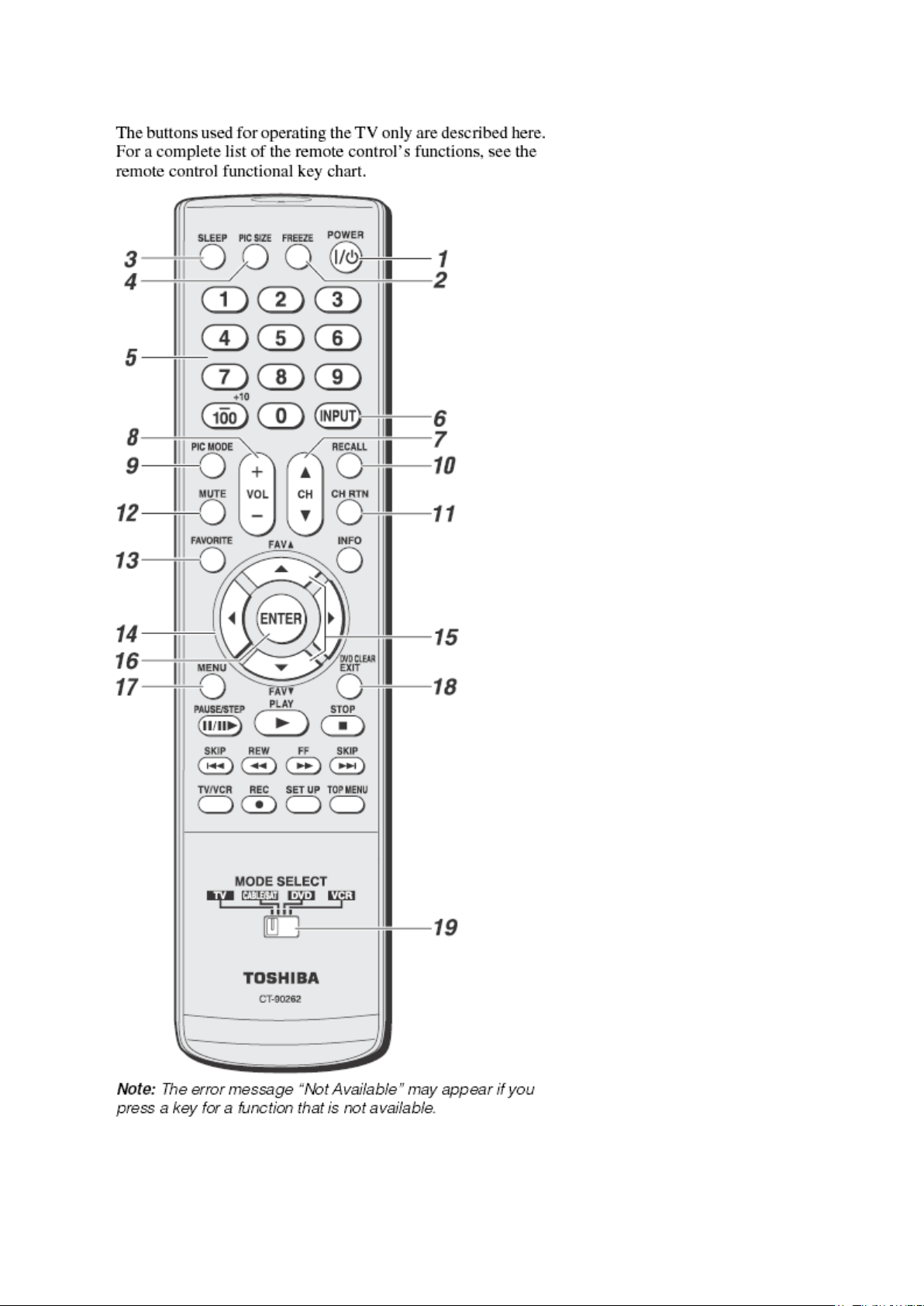
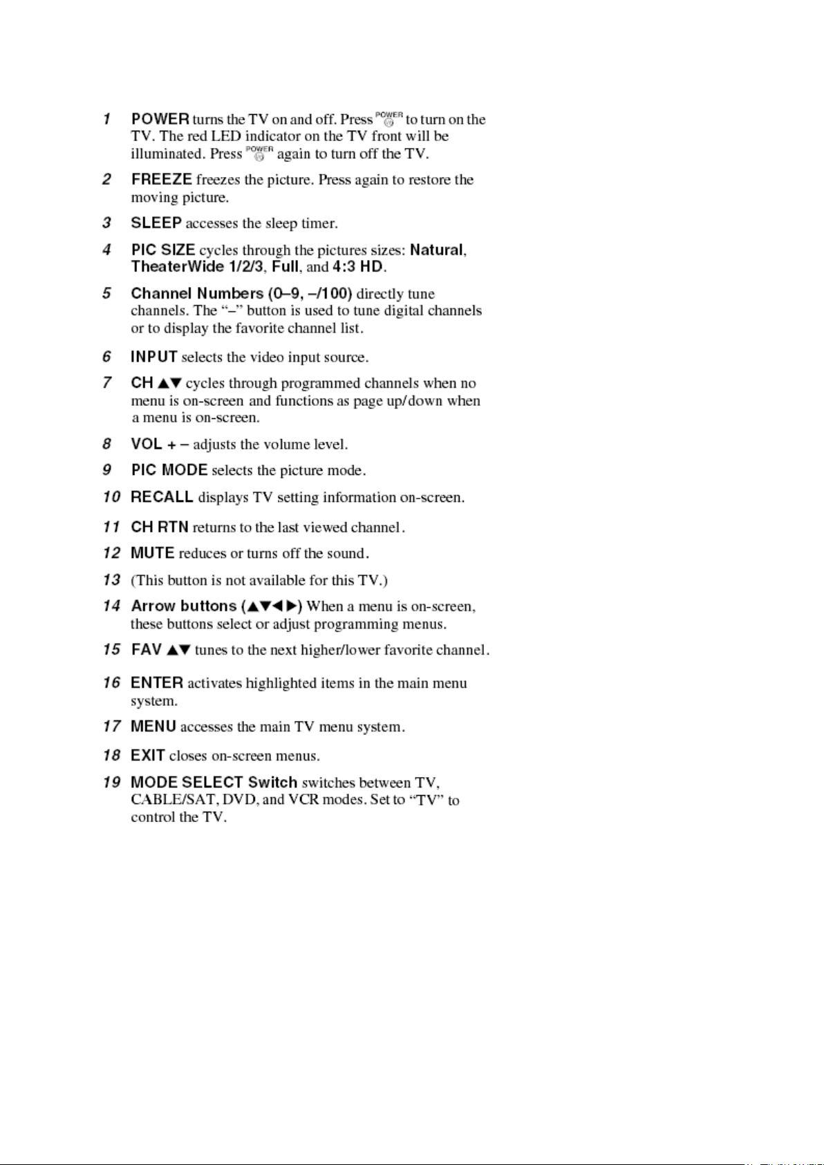
Learning about the Remote Control
Стр. 2 из
3
10.05.2015
file://C:\Documents and Settings\Alexsandr\Local Settings\Temp\Rar$EXa0.433\37H
...
Стр. 3 из
3
10.05.2015
file://C:\Documents and Settings\Alexsandr\Local Settings\Temp\Rar$EXa0.433\37H
...
FUNCTION AND OPERATION
Стр. 1 из
4
10.05.2015
file://C:\Documents and Settings\Alexsandr\Local Settings\Temp\Rar$EXa0.806\37H
...
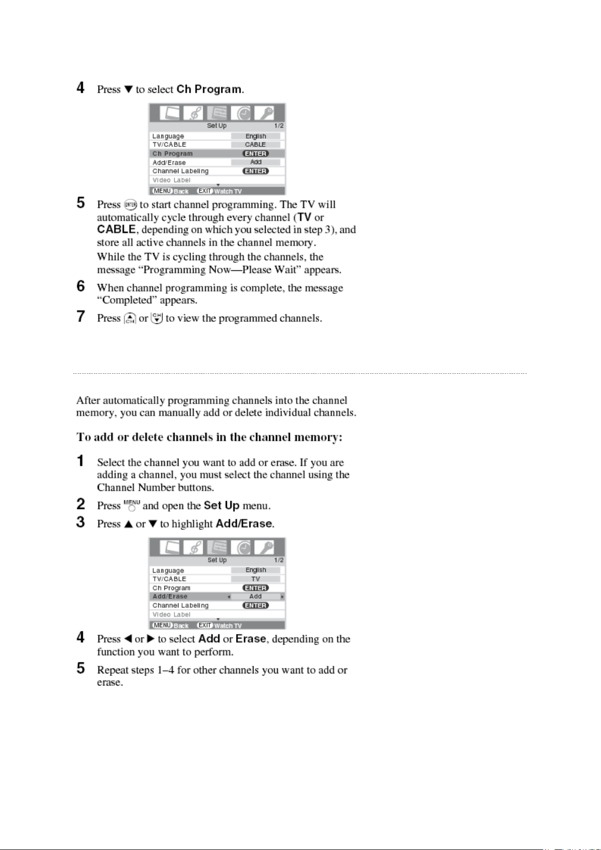
Programming Channel into the TV's Channel Memory
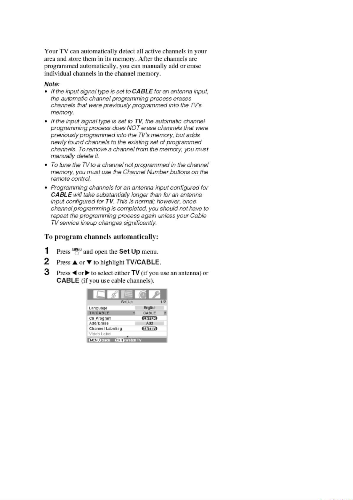
Programming Channel Automatically
Стр. 2 из
4
10.05.2015
file://C:\Documents and Settings\Alexsandr\Local Settings\Temp\Rar$EXa0.806\37H
...
Стр. 3 из
4
10.05.2015
file://C:\Documents and Settings\Alexsandr\Local Settings\Temp\Rar$EXa0.806\37H
...
Manually Adding and Deleting Channel in the Channel Memory

Стр. 4 из
4
10.05.2015
file://C:\Documents and Settings\Alexsandr\Local Settings\Temp\Rar$EXa0.806\37H
...
 Loading...