

Toshiba 37HL67S Schematic
SERVICE MANUAL
Стр. 1 из
1
10.05.2015
file://C:\Program Files\zeus\js\!!fcover.html
LCD Color Television
37HL67S
Ver. 2.00
This model is classified as a green product (*1), as indicated by the underlined serial number. This
Service Manual describes replacement parts for the green product. When repairing this green
product, use the part(s) described in this manual and lead-free solder (*2).
For (*1) and (*2), refer to
© TOSHIBA CORPORATION
GREEN PRODUCT PROCUREMENT
and
LEAD-FREE SOLDER
.
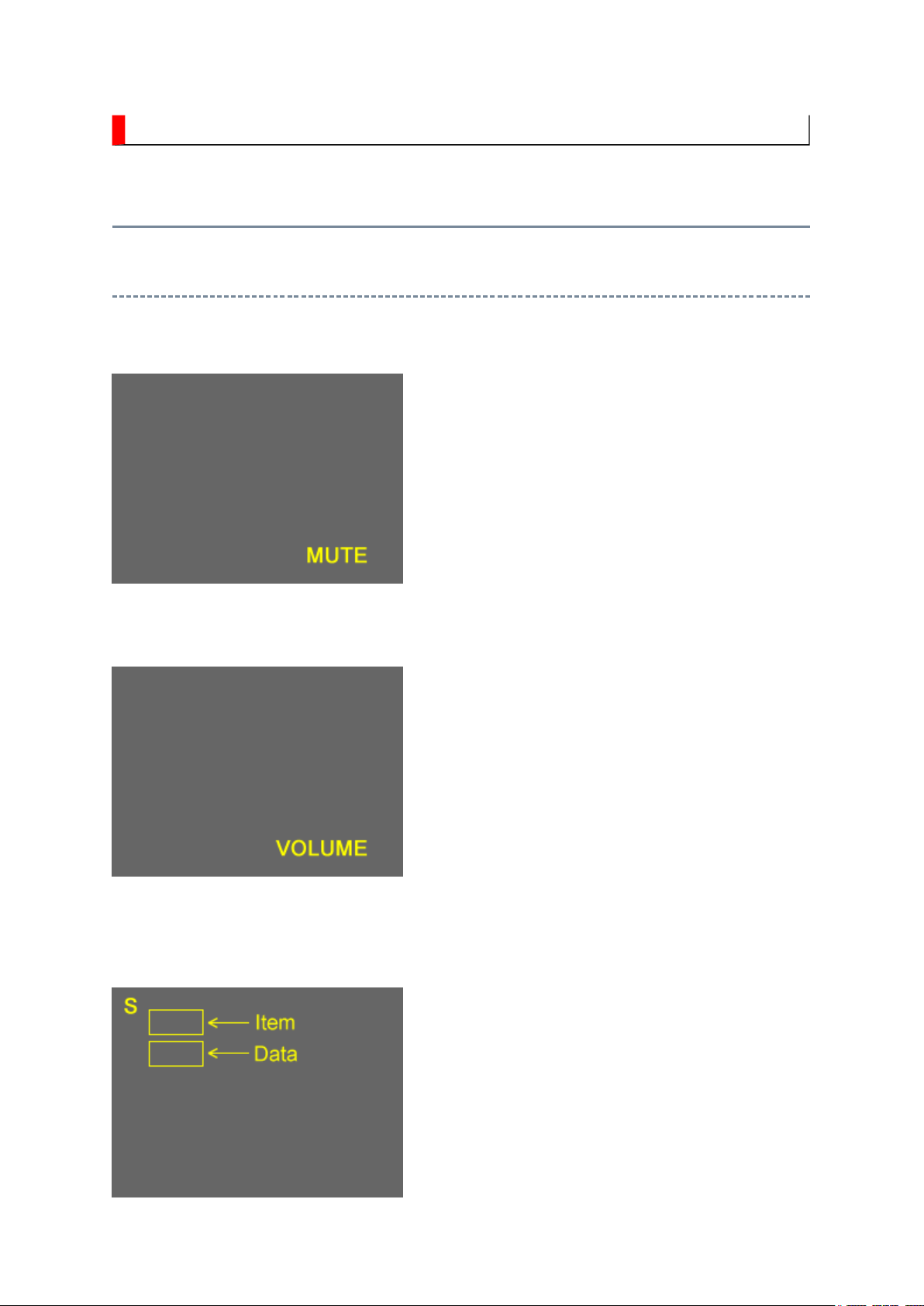
ADJUSTMENT
While holding the MUTE button, press MENU
Стр. 1 из 8ADJUSTMENT [LCD Color Television] ASIA_EU
10.05.2015
file://C:\Documents and Settings\Alexsandr\Local Settings\Temp\Rar$EXa0.867\37H
...
Service Mode
Entering to Service Mode
1. Set VOLUME to minimum and press MUTE
button twice on Control.
↓↓↓↓
↓↓↓↓
Service Mode display
2. Press MUTE button again and hold button
down.
3.
button on TV set.
Стр. 2 из 8ADJUSTMENT [LCD Color Television] ASIA_EU
10.05.2015
file://C:\Documents and Settings\Alexsandr\Local Settings\Temp\Rar$EXa0.867\37H
...
Key Function in the Service Mode
The following key entry during display of adjustment menu provides special functions.
Selection of the adjustment items CH (on TV or remote control)
Change of the data value Volume +/- (on TV or remote control)
Adjustment menu mode ON/OFF MENU button (on remote control)
Reset the count of operating
protect circuit to "00"
"RCUT" selection 1 button
"GCUT" selection 2 button
"BCUT" selection 3 button
"CNTX" selection 4 button
"COLC" selection 5 button
"UVTT" selection 6 button
Self diagnostic display ON/OFF 9 button
CALL + CH button on TV ( )
Selecting the Adjusting Item
Every pressing of CH button in the service mode changes the adjustment items in the
order of table below. ( button for reverse order)
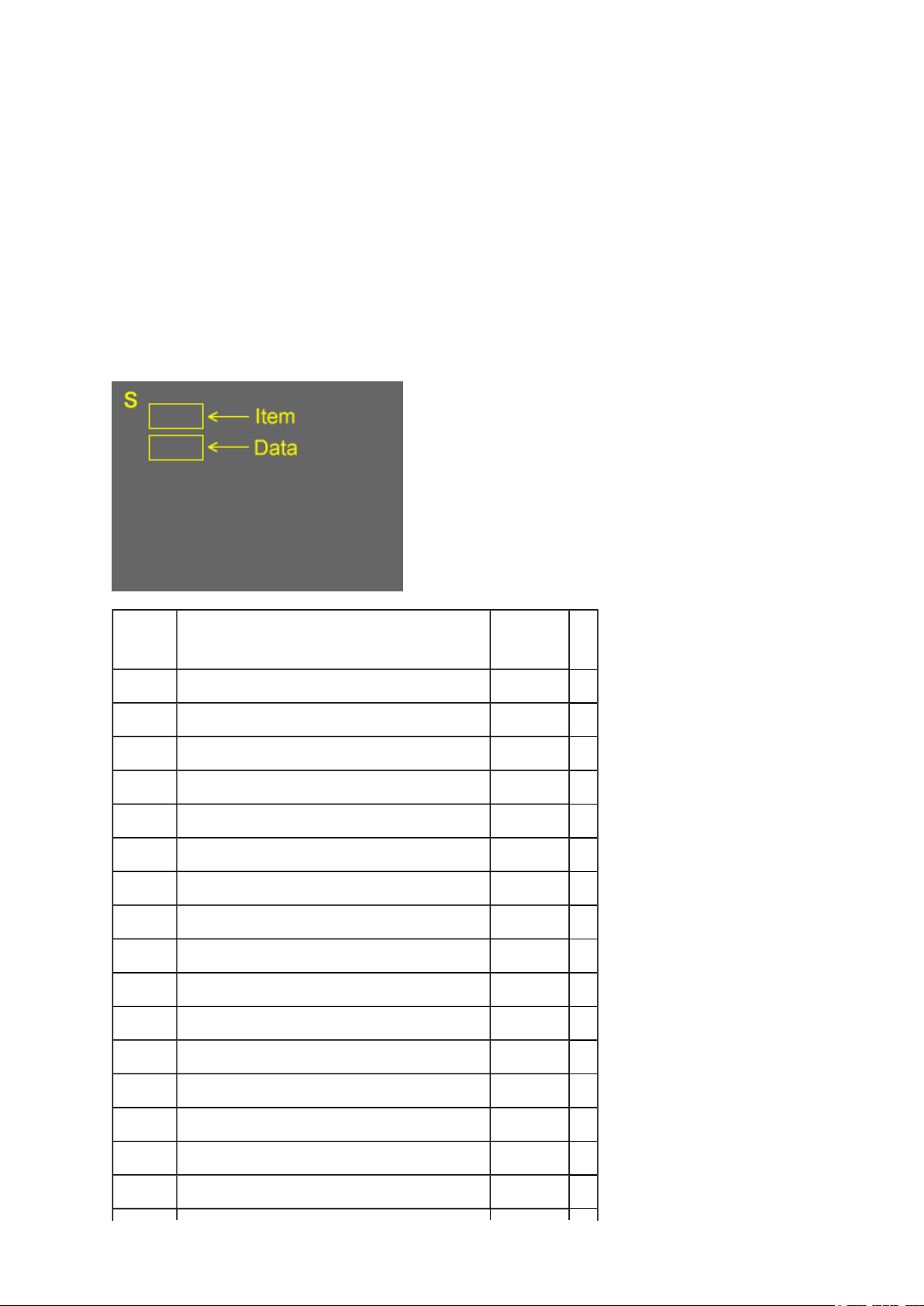
SETTING & ADJUSTING DATA
[ SERVICE MODE ]
ADJUSTING ITEMS AND DATA IN THE SERVICE MODE:
Note:
(1) The image system data may be different for each image format chosen. The factory
preset data value is indicated in the table.
(a) HOST-MICRO EEPROM data
Prior to changing any board containing an EEPROM IC, the exisiting data in each image
Стр. 3 из 8ADJUSTMENT [LCD Color Television] ASIA_EU
10.05.2015
file://C:\Documents and Settings\Alexsandr\Local Settings\Temp\Rar$EXa0.867\37H
...
DRAMA0543 for HL series
(b) TV-MICRO EEPROM data
DRAMA0589 for HL series
(2)
format should be copied down as a precautionary measure.
Item Name of adjustment Data
HL series
R-CUT R CUTOFF 00H (a)
G-CUT G CUTOFF 00H (a)
B-CUT B CUTOFF 00H (a)
R-DRV R DRIVE 64H (a)
G-DRV G DRIVE 64H (a)
B-DRV B DRIVE 64H (a)
*BRTC BRIGHTNESS CENTER 78H (a)
*COLC COLOR CENTER C0H (a)
*UVTT BASE BAND TINT 80H (a)
*CNTX CONTRAST MAX FFH (a)
SHRC SHARPNESS CENTER 60H (a)
VBIS VBI Setting 64H (a)
CC Closed Caption 64H (a)
ID1 VBID 64H (a)
GG Gemstar 00H (a)
BYBK B-Y OFF SET 00H (a)
RYBK R-Y OFF SET 00H (a)
Стр. 4 из 8ADJUSTMENT [LCD Color Television] ASIA_EU
10.05.2015
file://C:\Documents and Settings\Alexsandr\Local Settings\Temp\Rar$EXa0.867\37H
...
OPT1 TV SET OPTION 1 00H (b)
OPT2 TV SET OPTION 2 25H (b)
OPT3 TV SET OPTION 3 00H (b)
OPT4 TV SET OPTION 4 25H (b)
OPT5 TV SET OPTION 5 01H (b)
SET-ID MODEL ID *1 (b)
MAGC AGC of MTS decoder 00H (b)
VO1 Volume1 Data 5FH (b)
V25 Volume25 Data ADH (b)
V50 Volume50 Data DFH (b)
V75 Volume75 Data F9H (b)
V100 Volume100 Data FFH (b)
VOLBS Correction Volume at DTV 00H (b)
VOLST Correction Volume at Stereo/SAP of ATV 00H (b)
EVOL Reduce Volume For Bassboost (Nonuse) 00H (b)
VOLX Volume Limiter For Hotel 64H (b)
BASX Bass Max Data 1AH (b)
TREX Treble Max Data 1AH (b)
TONN Tone Min Data 08H (b)
BASC Bass center Data 01H (b)
TREC Treble center Data 03H (b)
EBAS Add Bass on FOCUS 00H (b)
ETRE Add Treble on FOCUS 01H (b)
WON2 Bass Reducer 11H (b)
ALS ALS point 00H (b)
ALOF Reduce in ALL (wow, TruSurround) off 01H (b)
VSTB Reduce Volume For Stable Sound 00H (b)
VS3D Reduce Volume For SRS3D 01H (b)
VFCS Reduce Volume For FOCUS 03H (b)
VTBH Reduce Volume For TruBass High 00H (b)
VTBL Reduce Volume For TruBass Low 00H (b)
button will change the value of data in the range from 00H to
VVDD Reduce Volume For Dolby F3H (b)
Стр. 5 из 8ADJUSTMENT [LCD Color Television] ASIA_EU
10.05.2015
file://C:\Documents and Settings\Alexsandr\Local Settings\Temp\Rar$EXa0.867\37H
...
WFCS FOCUS Level 01H (b)
WWSP SRS 3D Level 02H (b)
WTBH TruBass High Level 03H (b)
WTBL TruBass Low Level 02H (b)
VOLM Volume coefficient at 1/2 Mute 32H (b)
Factory preset data will be loaded after setting Model ID data.
Note:
(*1) SET-ID data is subject to the models.
Refer to Setting Panel Option Data and SET-ID Data for detail.
Adjusting the Data
Pressing of VOLUME or
FFH. The variable range depends on the adjusting item.
Setting Panel Option Data and SET-ID Data
1. Panel option data is subject to OP4 and OP5.
Enter to service mode and select menu of OP4 or OP5 by pressing P or P during
Display of adjustment menu. After selecting OPT4 or OPT5, press + or - to set
OPT4 or OPT5 value as table below.
2. Whenever using new AV-TN board to the set, set the SET-ID data according to panel
option data.
Set Size
HL47 26 CMO - 33h - 00h 01h A7h
HL67US 32 SAMSUNG - 65h - 00h 01h A8h
HL67S 37 AUO - 46h - 00h 01h A9h
HL67US 42 AUO - 47h - 00h 01h AAh
Panel Maker OPT4
TOP Running change TOP Running change
OPT3 OPT5 SET-ID
Exit from Service Mode
Стр. 6 из 8ADJUSTMENT [LCD Color Television] ASIA_EU
10.05.2015
file://C:\Documents and Settings\Alexsandr\Local Settings\Temp\Rar$EXa0.867\37H
...
Pressing POWER button to turn off the TV once.
Self Diagnostic Function
1. Press "Recall" button on Remote Control during display of adjustment menu in the
service mode. This will bring up the "S" in the right corner of screen. Now press "9"
button on remote.
The diagnosis will begin to check if interface among IC's is executed properly.
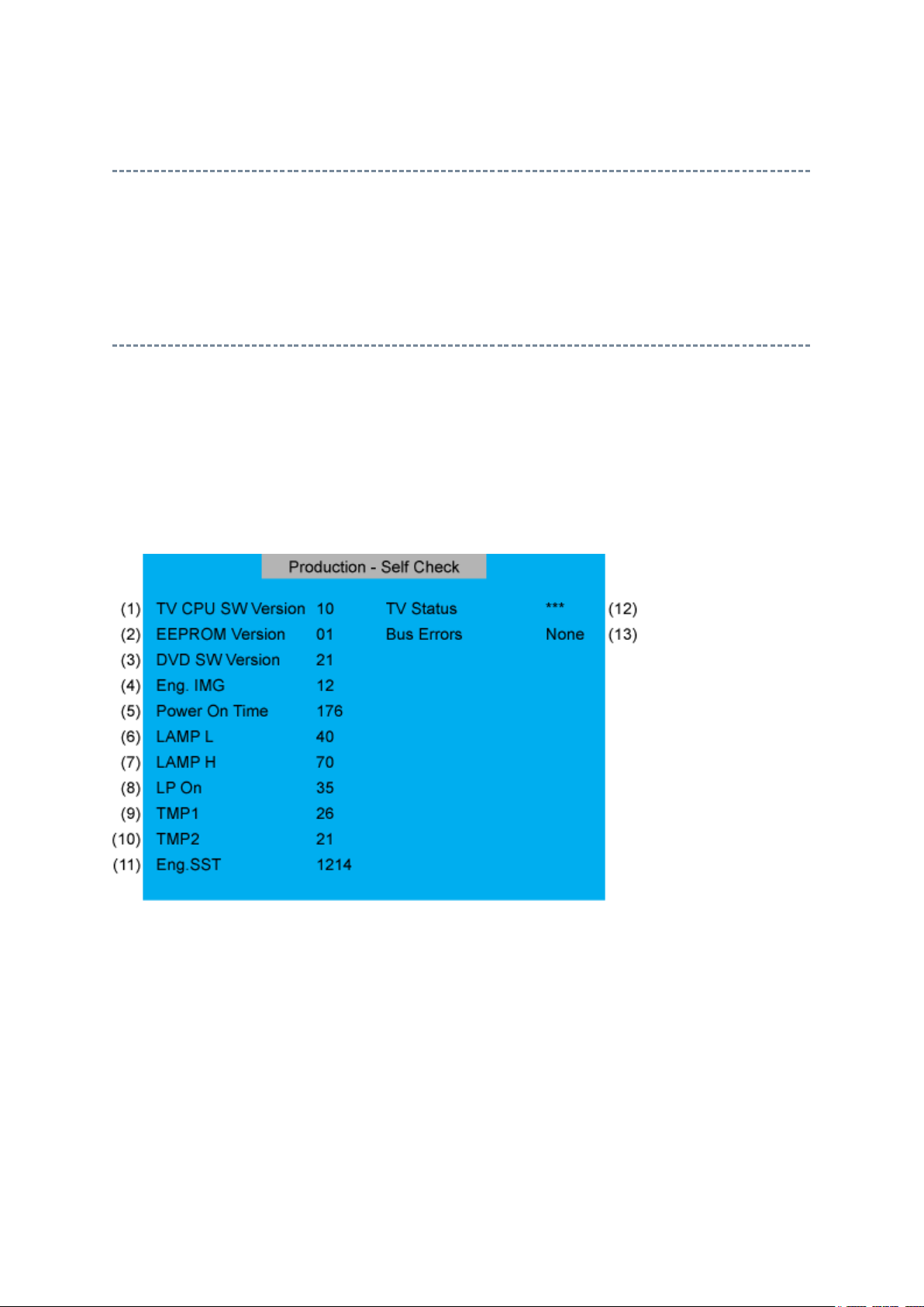
2. During diagnosis, the following displays are shown.
(1) Version information of TV-MICRO : Display 1 byte data.
(2) Version information of TV-MICRO EEPROP : Display 1 byte data.
(3) Version information of DVD MPU : HL series not used.
(4) Revision of image file : LCD Model not used.
(5) Total brightness hour of TV. : Display 4 bytes data.
(6) Operation hour of TV in LOW mode : Display 4 bytes data.
(7) Operation hour of TV in HIGH BRIGHT mode : LCD Model not used.
(8) Number of times of TV ON/OFF. : LCD Model not used.
Стр. 7 из 8ADJUSTMENT [LCD Color Television] ASIA_EU
10.05.2015
file://C:\Documents and Settings\Alexsandr\Local Settings\Temp\Rar$EXa0.867\37H
...
(9) Temperature display of thermo-Sensor. (DMD) : LCD Model not used.
(10) Temperature display of thermo-Sensor. (LAMP) : LCD Model not used.
(11) DMD Engine System status : LCD Model not used.
(12) TV-MICRO System status : Not used
(13) IIC-BUS status
Bus line normal is "None" displayed.
When it is abnormal, the block name is displayed as follows.
"SCL-GND" (Red indication) : SCL-GND short circuit
"SDA-GND" (Red indication) : SDA-GND short circuit
"SCL-SDA" (Red indication) : SCL-SDA short circuit
"NG : MTS"
"NG : APRO"
"NG : AVSW"
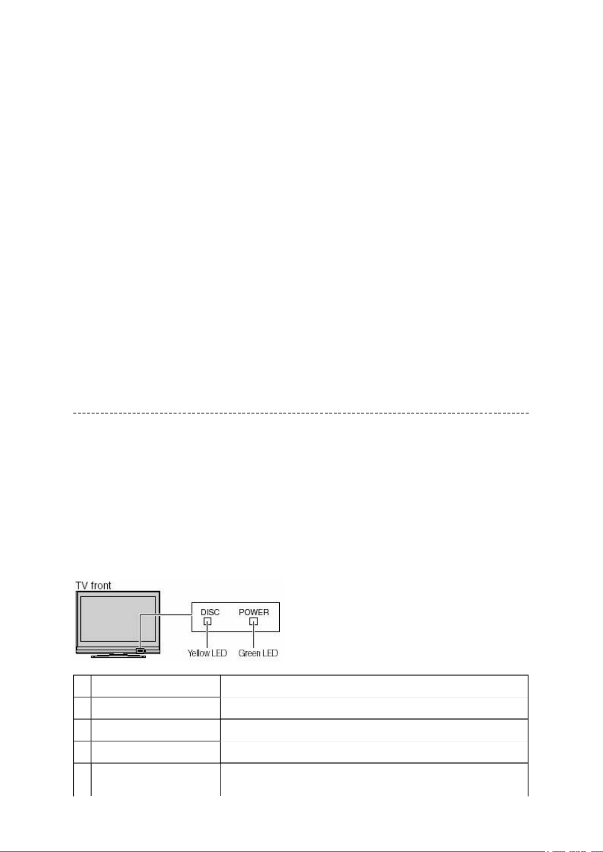
LED Indication
The yellow, blue and red/green LED lights on the TV (at the bottom center of the TV)
indicate the TV's status, as described below:
Note:
unplugged), when power is restored, the yellow LED will blink while the TV is booting until
the remote control is usable. This is normal and is not a sign of malfunction.
If the TV loses A/C power (e.g., a power outage occurs or the power cord is
LED Indication Condition
1 Green and Yellow are off. Power supply OFF. (AC)
2 Green and Yellow are off. Power supply OFF. (Stand by)
3 Green is on (solid). The TV is operating properly.
4 Yellow is on (solid). Power-On Mode set into the quick operation.
The power is supplied to Digital Board only.
Стр. 8 из 8ADJUSTMENT [LCD Color Television] ASIA_EU
10.05.2015
file://C:\Documents and Settings\Alexsandr\Local Settings\Temp\Rar$EXa0.867\37H
...
5 Green blinks. Fan stop detection.
6 Green blinks slowly. Abnormal operation of BUS line.
Turn the TV off and unplug the power cord, then plug the
power cord in again and turn the TV on.
7 Green blinks quickly. Power Protection Detection.
Turn the TV off and unplug the power cord, then plug the
power cord in again and turn the TV on.
8 Yellew blinks 3 times. The TV is rebooting.
Wait several seconds until the yellow LED stops blinking.
9 Green is on (solid).
Yellow is on (solid).
10 Green is on (solid).
Yellow is off.
11 Green is off.
Yellow is on (solid).
Upgrading in progress.
Upgrading succesful.
Upgrading failed.
FUNCTION AND OPERATION
Стр. 1 из
2
10.05.2015
file://C:\Documents and Settings\Alexsandr\Local Settings\Temp\Rar$EXa0.739\37H
...
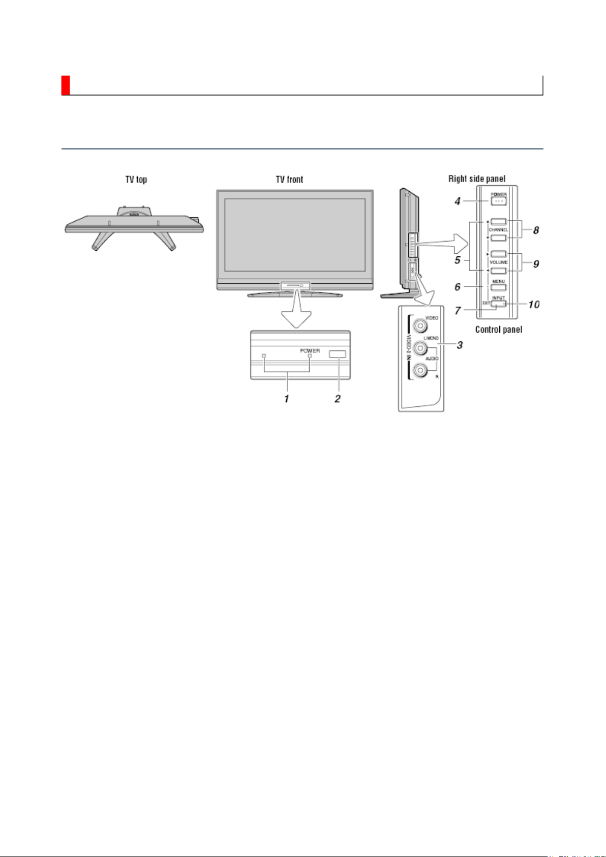
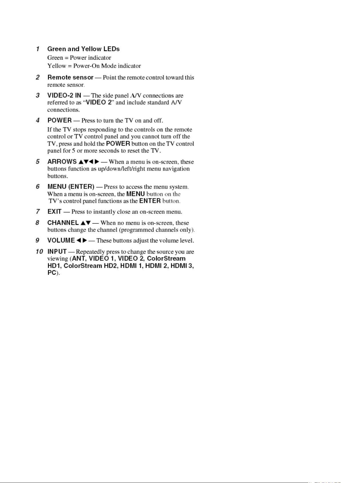
TV Front and Side Panel Control and Connection
Стр. 2 из
2
10.05.2015
file://C:\Documents and Settings\Alexsandr\Local Settings\Temp\Rar$EXa0.739\37H
...

FUNCTION AND OPERATION
Стр. 1 из
3
10.05.2015
file://C:\Documents and Settings\Alexsandr\Local Settings\Temp\Rar$EXa0.638\37H
...
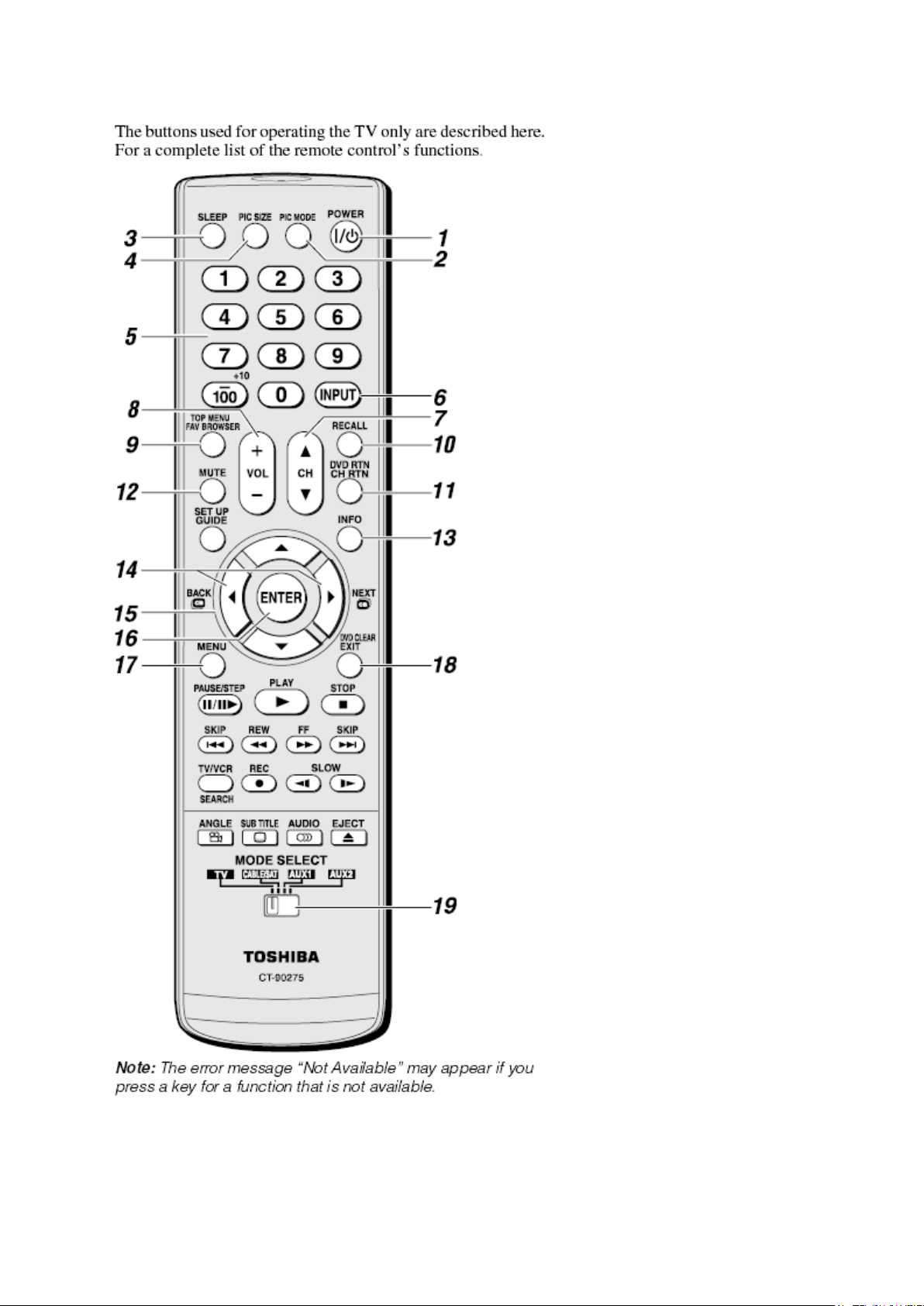
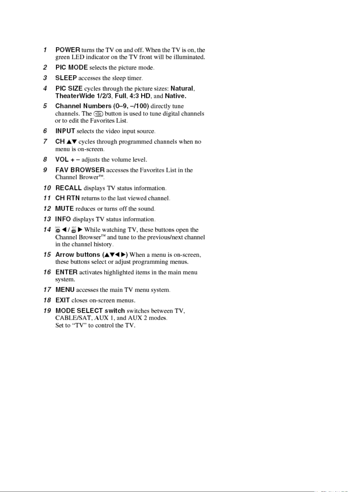
Learning about the Remote Control
Стр. 2 из
3
10.05.2015
file://C:\Documents and Settings\Alexsandr\Local Settings\Temp\Rar$EXa0.638\37H
...
Стр. 3 из
3
10.05.2015
file://C:\Documents and Settings\Alexsandr\Local Settings\Temp\Rar$EXa0.638\37H
...
FUNCTION AND OPERATION
Стр. 1 из
4
10.05.2015
file://C:\Documents and Settings\Alexsandr\Local Settings\Temp\Rar$EXa0.407\37H
...
Programming Channel into the TV's Channel Memory
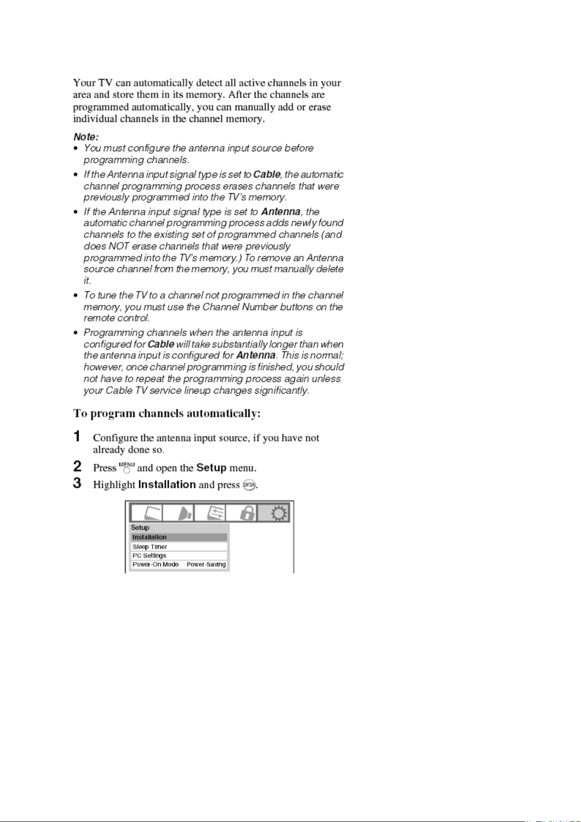
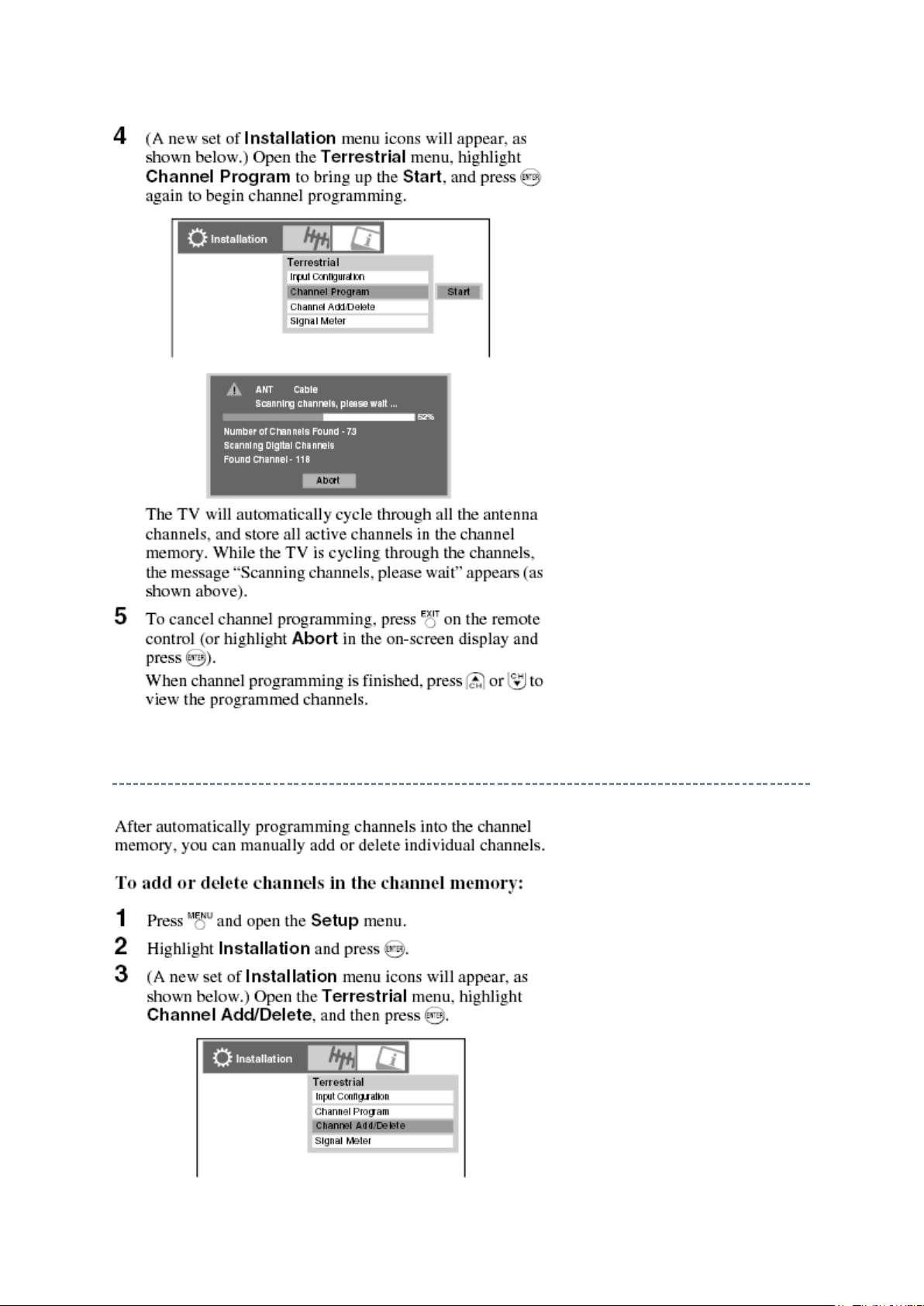
Programming Channel Automatically
Стр. 2 из
4
10.05.2015
file://C:\Documents and Settings\Alexsandr\Local Settings\Temp\Rar$EXa0.407\37H
...
Стр. 3 из
4
10.05.2015
file://C:\Documents and Settings\Alexsandr\Local Settings\Temp\Rar$EXa0.407\37H
...
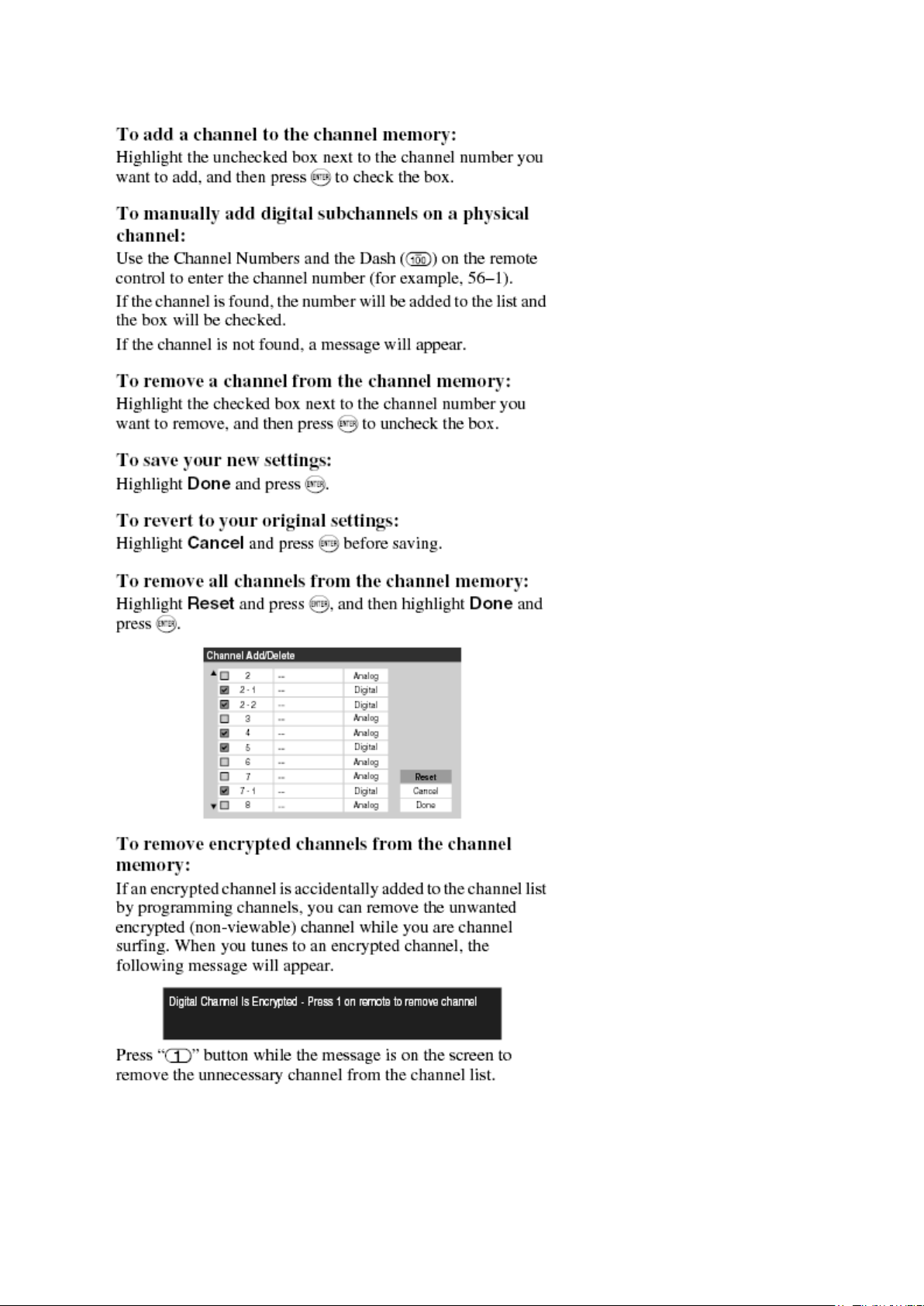
Manually Adding and Deleting Channel in the Channel Memory
Стр. 4 из
4
10.05.2015
file://C:\Documents and Settings\Alexsandr\Local Settings\Temp\Rar$EXa0.407\37H
...
SAFETY INSTRUCTION
should enter the mouth, rinse the mouth thoroughly with water. If the fluid should contact the
When attaching the LCD module to the LCD cover, position it appropriately and fasten
Стр. 1 из 4Handling the LCD Module
10.05.2015
file://C:\Documents and Settings\Alexsandr\Local Settings\Temp\Rar$EXa0.678\37H
...
Handling the LCD Module
Safety Precaution
In the event that the screen is damaged or the liquid crystal (fluid) leaks, do not breathe in or
drink this fluid.
Also, never touch this fluid. Such actions could cause toxicity or skin irritation. If this fluid
skin or clothing, wipe off with alcohol, etc., and rinse thoroughly with water. If the fluid
should enter the eyes, immediately rinse the eyes thoroughly with running water.
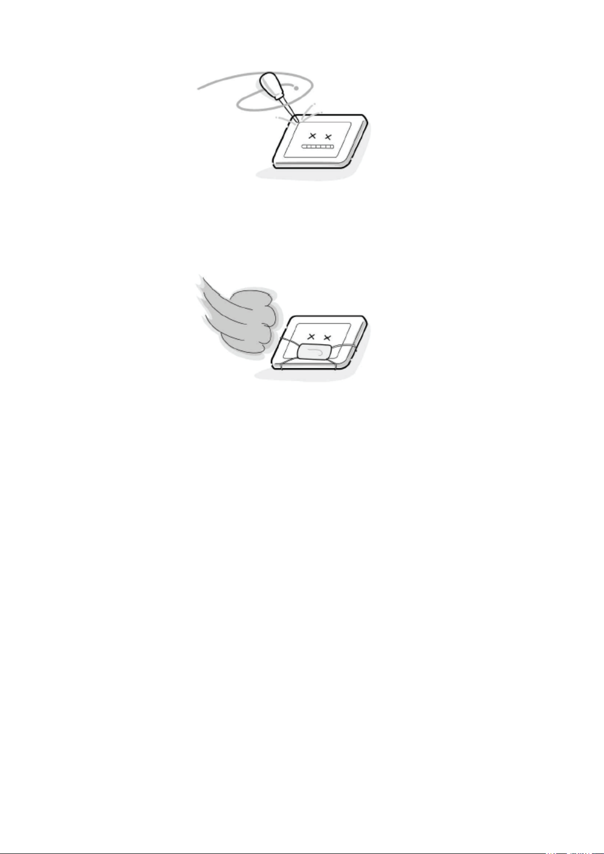
Precautions for Handling the LCD Module
CAUTION: The metal edges of the LCD module are sharp, handle it with
care.
The LCD module can easily be damaged during disassembly or reassembly; therefore,
always observe the following precautions when handling the module.
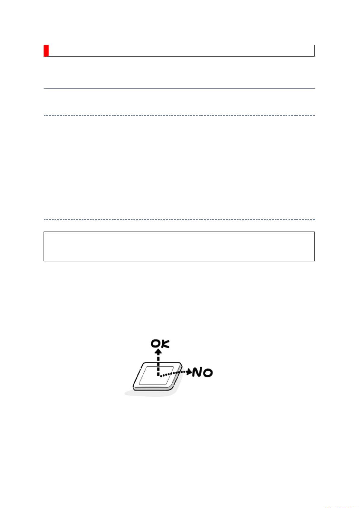
1.
at the position where the display can be viewed most conveniently.
2. Carefully align the holes at all four corners of the LCD module with the corresponding
holes in the LCD cover and fasten with screws. Do not strongly push on the module
because any impact can adversely affect the performance. Also use caution when
handling the polarized screen because it can easily be damaged.
Стр. 2 из 4Handling the LCD Module
10.05.2015
file://C:\Documents and Settings\Alexsandr\Local Settings\Temp\Rar$EXa0.678\37H
...
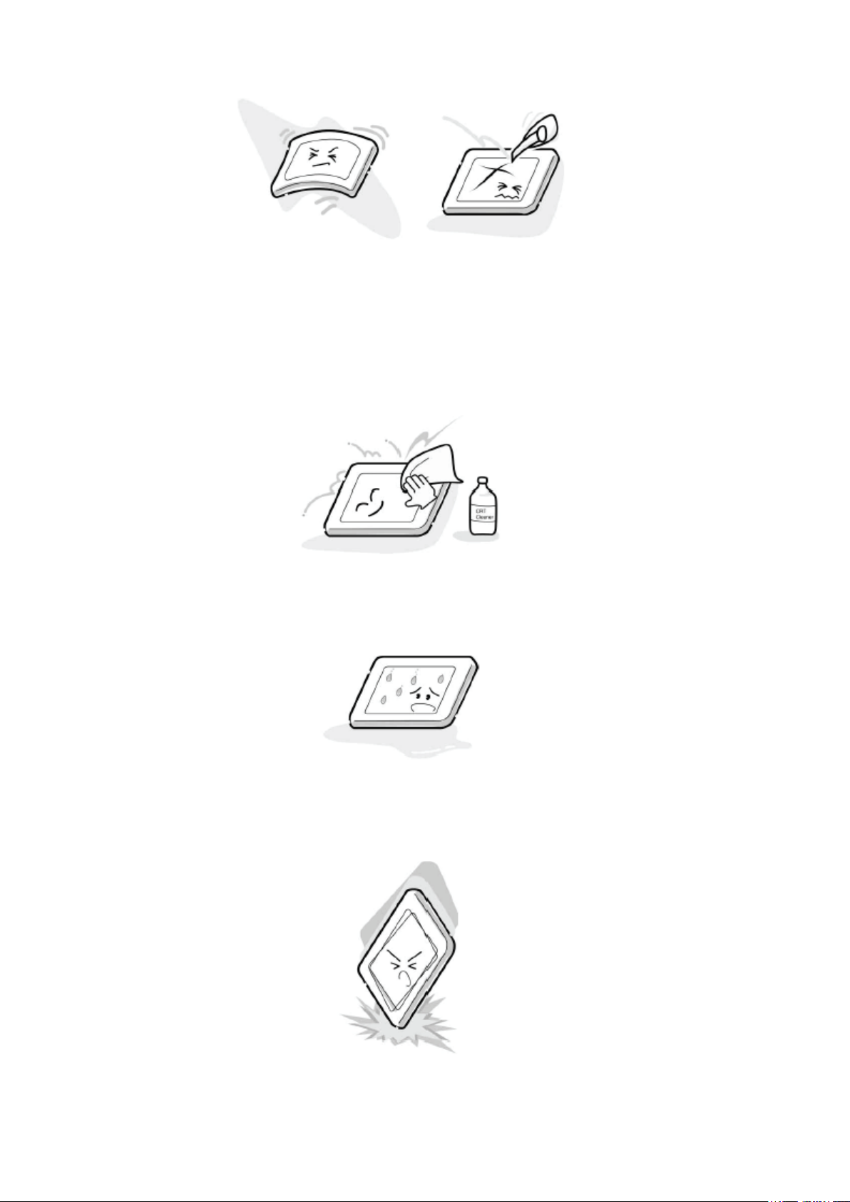
3. If the panel surface becomes soiled, wipe with cotton or a soft cloth. If this does not
remove the soiling, breathe on the surface and then wipe again.
If the panel surface is extremely solied, use a CRT cleaner as a cleaner. Wipe off the
panel surface by drop the cleaner on the cloth. Do not drop the cleaner on the panel.
Pay attention not to scratch the panel surface.
4. Leaving water or other fluids on the panel screen for an extended period of time can
result in discoloration or stripes. Immediately remove any type of fluid from the screen.
5. Glass is used in the panel, so do not drop or strike with hard objects. Such actions can
damage the panel.
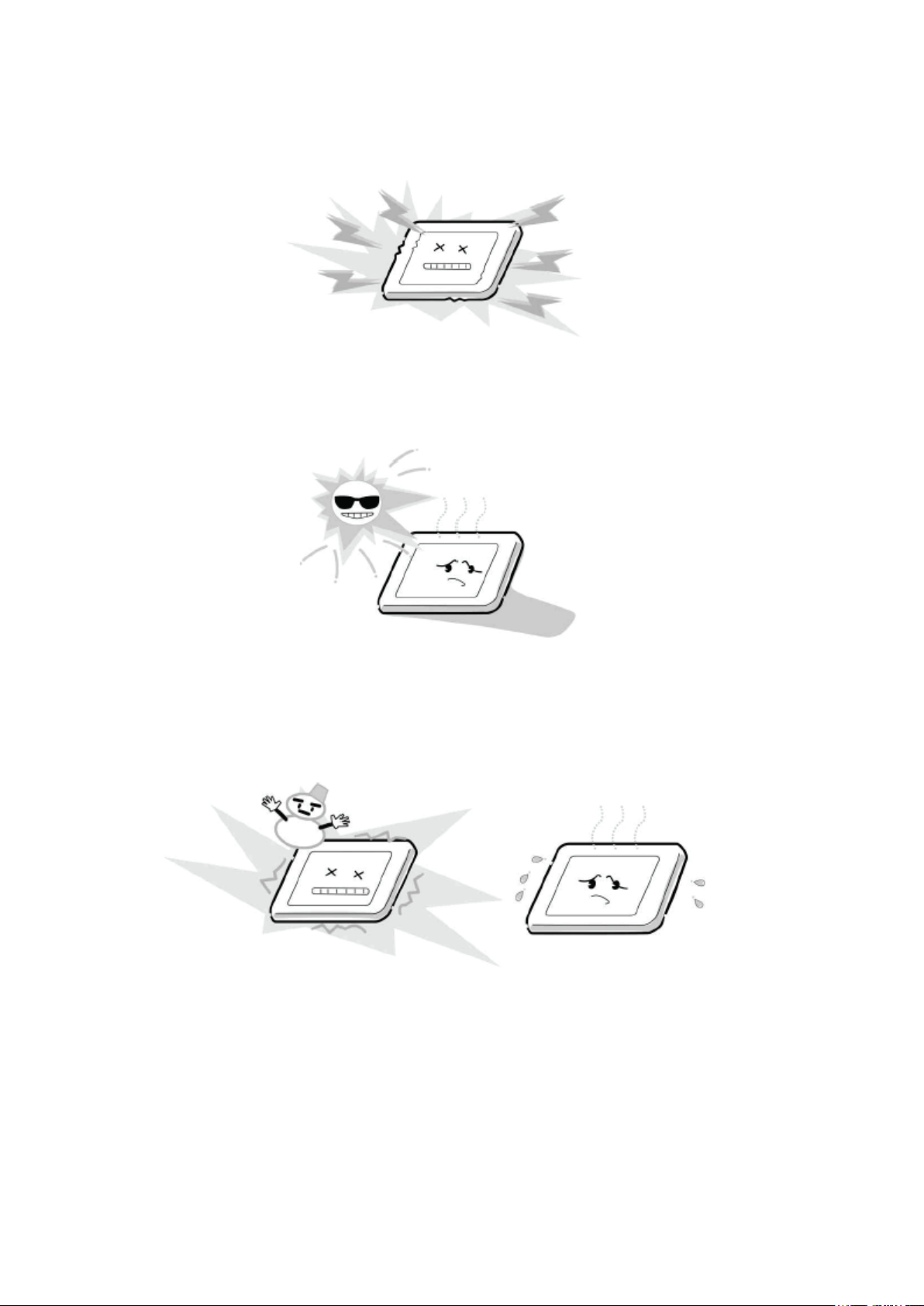
6. CMOS-LSI circuitry is used in the LCD module, so avoid damage due to static
Стр. 3 из 4Handling the LCD Module
10.05.2015
file://C:\Documents and Settings\Alexsandr\Local Settings\Temp\Rar$EXa0.678\37H
...
electricity. When handling the module, use a wrist ground or anchor ground.
7. Do not expose the LCD module to direct sunlight or strong ultraviolet rays for an
extended period of time.
8. Do not store the LCD module below the temperature conditions described in the
specifications. Failure to do so could result in freezing of the liquid crystal due to cold
air or loss of resilience or other damage.
9. Do not disassemble the LCD module. Such actions could result in improper operation.
Стр. 4 из 4Handling the LCD Module
10.05.2015
file://C:\Documents and Settings\Alexsandr\Local Settings\Temp\Rar$EXa0.678\37H
...
10. When transporting the LCD module, do not use packing containing epoxy resin
(amine) or silicon resin (alcohol or oxim). The gas generated by these materials can
cause loss of polarity.
PANEL IDENTIFICATION
name, the identification marking will be shown at the last digit of the set serial number on the
Стр. 1 из
1
10.05.2015
file://C:\Documents and Settings\Alexsandr\Local Settings\Temp\Rar$EXa0.753\37H
...
Panel Identification
If the several panels are alternatively used in the same model without amending the model
specification label on the back cover.
In servicing, do not alter the panel because several setting and parts are different.
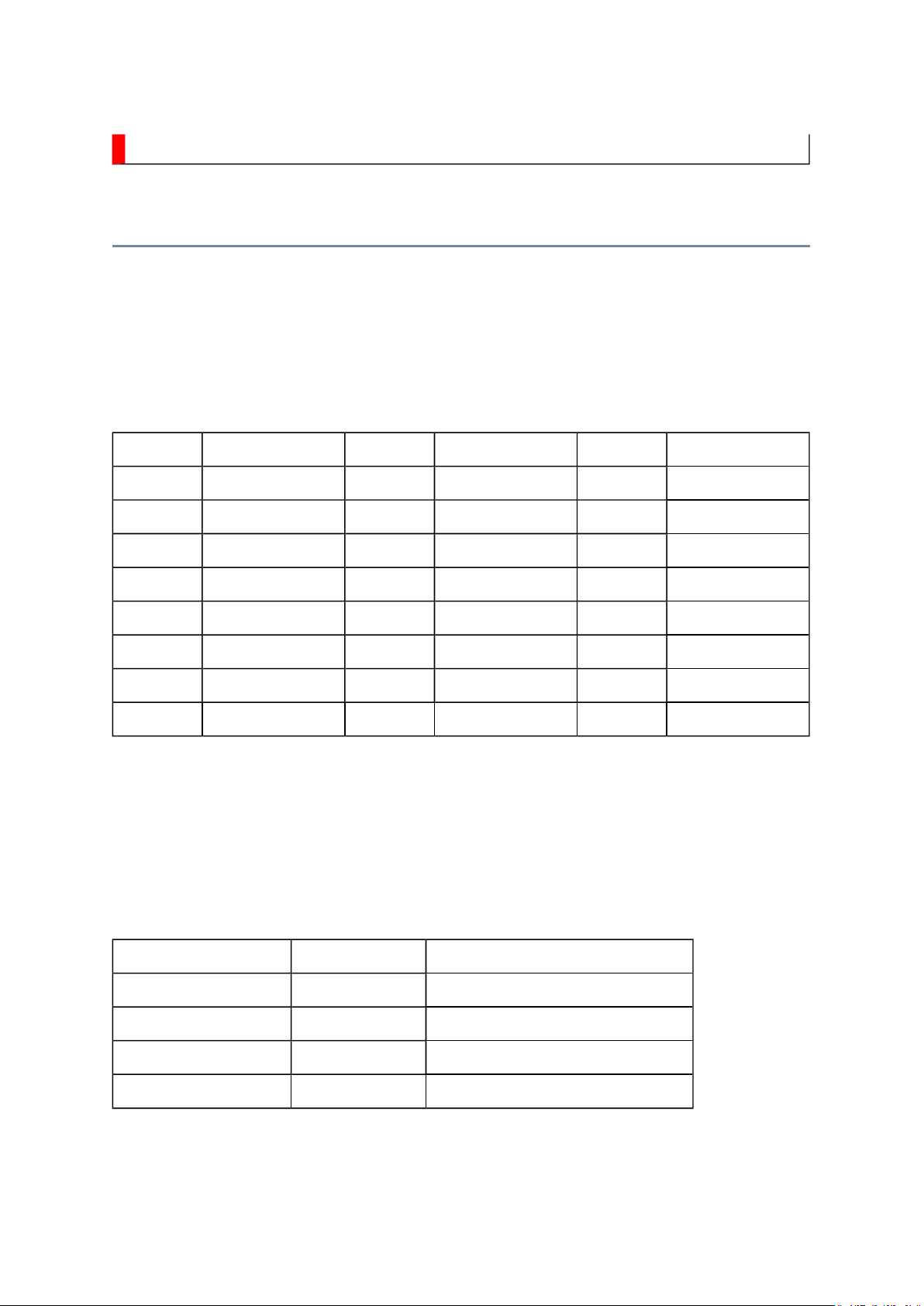
Marking Panel Vendor Marking Panel Vendor Marking Panel Vendor
A AUO J
B
C CMO L LPL U
D
E
F
G
H IPS R
K SAMSUNG T
M
N
P
Q
S SHARP
V
W
X
Y
Z
With this alternative use, some of key parts may differ and their combinations are
indicated with the suffix marking on the location number in the part list
(Miscellaneous).
e.g.
Location No. Part No. Description
B001A
B001B
MZ01A
MZ01B
75007869 LCD Panel, 32" LPL
75007870 LCD Panel, 32" AUO
75006036 LDVS Cable
75007893 LDVS Cable
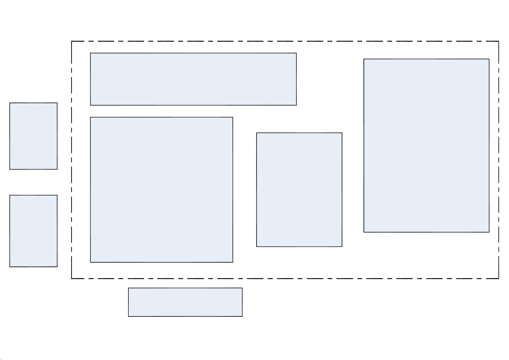
U03D
U02A LOW-B
KEY
U03B
Front-AV
U01A POWER
U04A
U03A TN-AV
SIGNAL
U03C LED
SAFETY INSTRUCTION
Always keep tools, components of the product, etc away from the children, These items
Стр. 1 из
3
10.05.2015
file://C:\Documents and Settings\Alexsandr\Local Settings\Temp\Rar$EXa0.604\37H
...
WARNING: BEFORE SERVICING THIS CHASSIS, READ THE "SAFETY
PRECAUTION" AND "PRODUCT SAFETY NOTICE" INSTRUCTIONS BELOW.
Safety Precaution
WARNING: SERVICING SHOULD NOT BE ATTEMPTED BY ANYONE
UNFAMILIAR WITH THE NECESSARY PRECAUTIONS ON THIS RECEIVER.
THE FOLLOWING ARE THE NECESSARY PRECAUTIONS TO BE OBSERVED
BEFORE SERVICING THIS CHASSIS.
1. An isolation transformer should be connected in the power line between the receiver
and the AC line before any service is performed on the receiver.
2. Always disconnect the power plug before any disassembling of the product. It may
result in electrical shock.
3. When replacing a chassis in the cabinet, always be certain that all the protective
devices are put back in place, such as nonmetallic control knobs, insulating covers,
shields, isolation resistor-capacitor network, etc.
4.
may cause injury to children.
5. Depending on the model, use an isolation transformer or wear suitable gloves when
servicing with the power on, and disconnect the power plug to avoid electrical shock
when replacing parts. In some cases, alternating current is also impressed in the
chassis, so electrical shock is possible if the chassis is contacted with the power on.
6. Always use the replacement parts specified for the particular model when making
repairs. The parts used in products require special safety characteristics such as

inflammability, voltage resistance, etc. therefore, use only replacement parts that have
NEVER remodel the product in any way. Remodeling can result in improper operation,
cabinet such as antennas, terminals, screw heads, metal overlays, control shafts and etc.
The leakage current checking. (After completing the work, measure the leakage current
Стр. 2 из
3
10.05.2015
file://C:\Documents and Settings\Alexsandr\Local Settings\Temp\Rar$EXa0.604\37H
...
these same characteristics. Use only the specified parts when the mark is indicated
in the circuit diagram or parts list.
7. Parts mounting and routing dressing of wirings should be the same as that used
originally. For safety purposes, insulating materials such as isolation tube or tape are
sometimes used and printed circuit boards are sometimes mounted floating. Also make
sure that wirings is routed and clamped to avoid parts that generate heat and which use
high voltage. Always follow the manufactured wiring routes / dressings.
8. Always ensure that all internal wirings are in accordance before re-assembling the
external casing after a repairing completed. Do not allow internal wiring to be pinched
by cabinets, panels, etc. Any error in reassembly or wiring can result in electrical
leakage, flame, etc., and may be hazardous.
9.
malfunction, or electrical leakage and flame, which may be hazardous.
10. Always perform an AC leakage current checking on the exposed metallic parts of the
to be sure that the set is safe to operate without any dangerous of electrical shocks
before returning the set to the customer.
11.
to prevent an electrical shock.)
Plug the AC line cord directly into a 120V AC outlet. Do not use an isolation
transformer for this check.
Use an AC voltmeter having 5000 ohms per volt or more sensitivity in the following
manner.
Connect a 1500 ohm 10 watt resistor, paralleled by a 0.15 µF, AC type capacitor,
between a known good earth ground (water pipe, conduit, etc.) and the exposed
metallic parts, one at a time. Measure the AC voltage across the combination of 1500
ohm resistor and 0.15 µF capacitor. Reverse the AC plug at the AC outlet and repeat
AC voltage measurements for each exposed metallic part. Voltage measured must not
exceed 0.3 volts rms. This corresponds to 0.2 milliamp. AC. Any value exceeding this
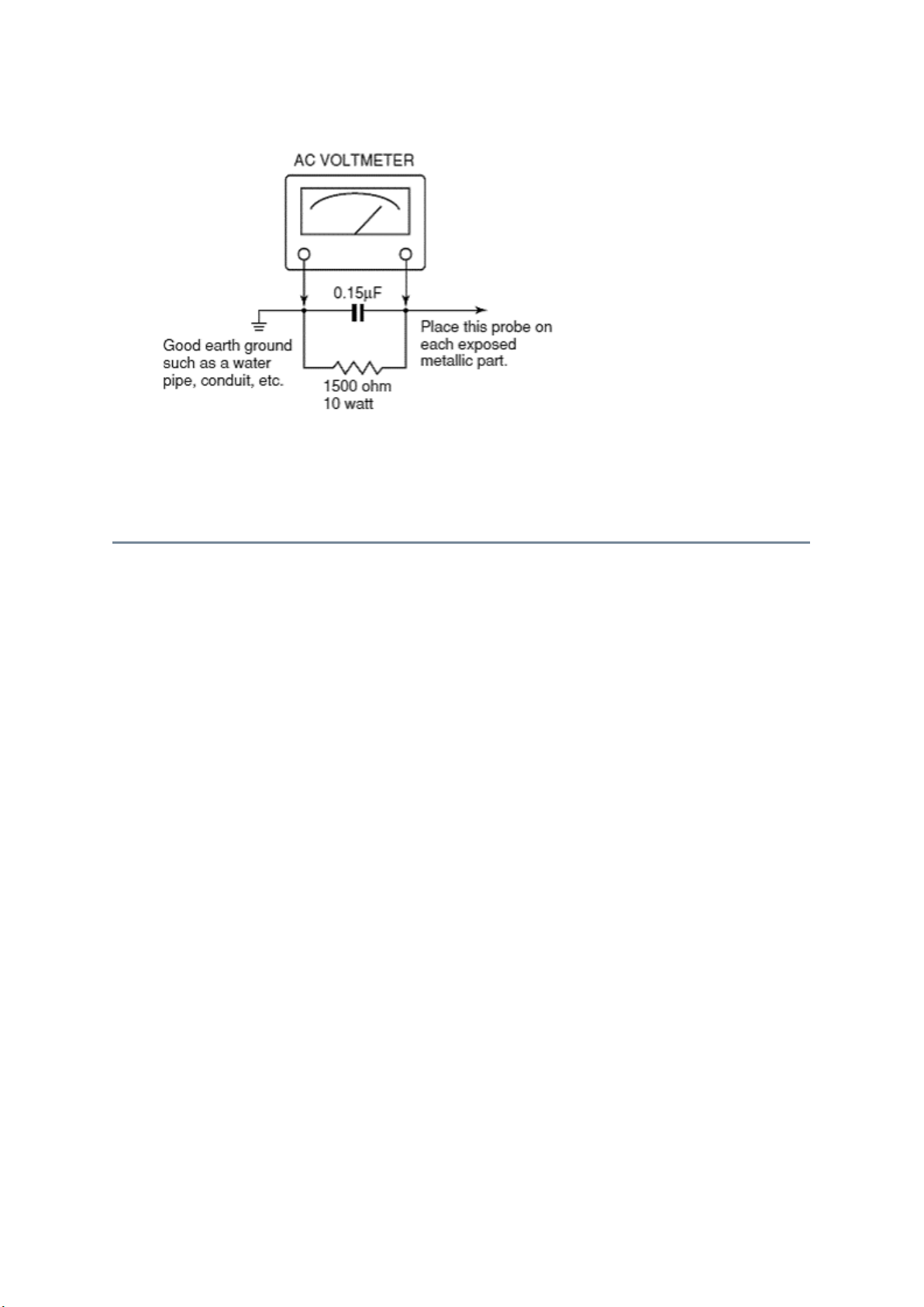
limit constitutes a potential shock hazard and must be corrected immediately.
Стр. 3 из
3
10.05.2015
file://C:\Documents and Settings\Alexsandr\Local Settings\Temp\Rar$EXa0.604\37H
...
Product Safety Notice
Many electrical and mechanical parts in this chassis have special safety-related
characteristics. These characteristics are often passed unnoticed by a visual inspection and
the protection afforded by them cannot necessarily be obtained by using replacement
components rated for higher voltage, wattage, etc. Replacement parts which have these
special safety characteristics are identified in this manual and its supplements; electrical
components having such features are identified by the international hazard symbols on the
schematic diagram and the parts list.
Before replacing any of these components, read the parts list in this manual carefully. The
use of substitute replacement parts which do not have the same safety characteristics as
specified in the parts list may create electrical shock, fire, or other hazards.
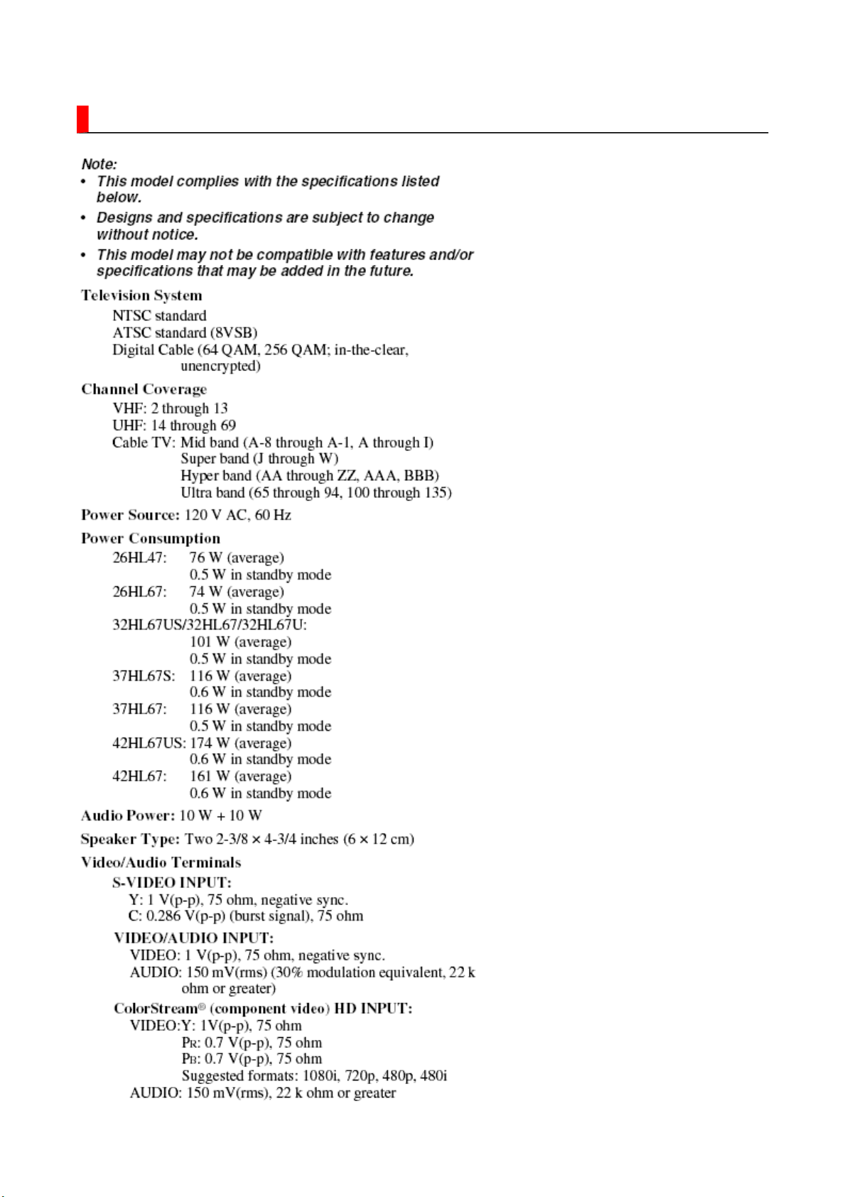
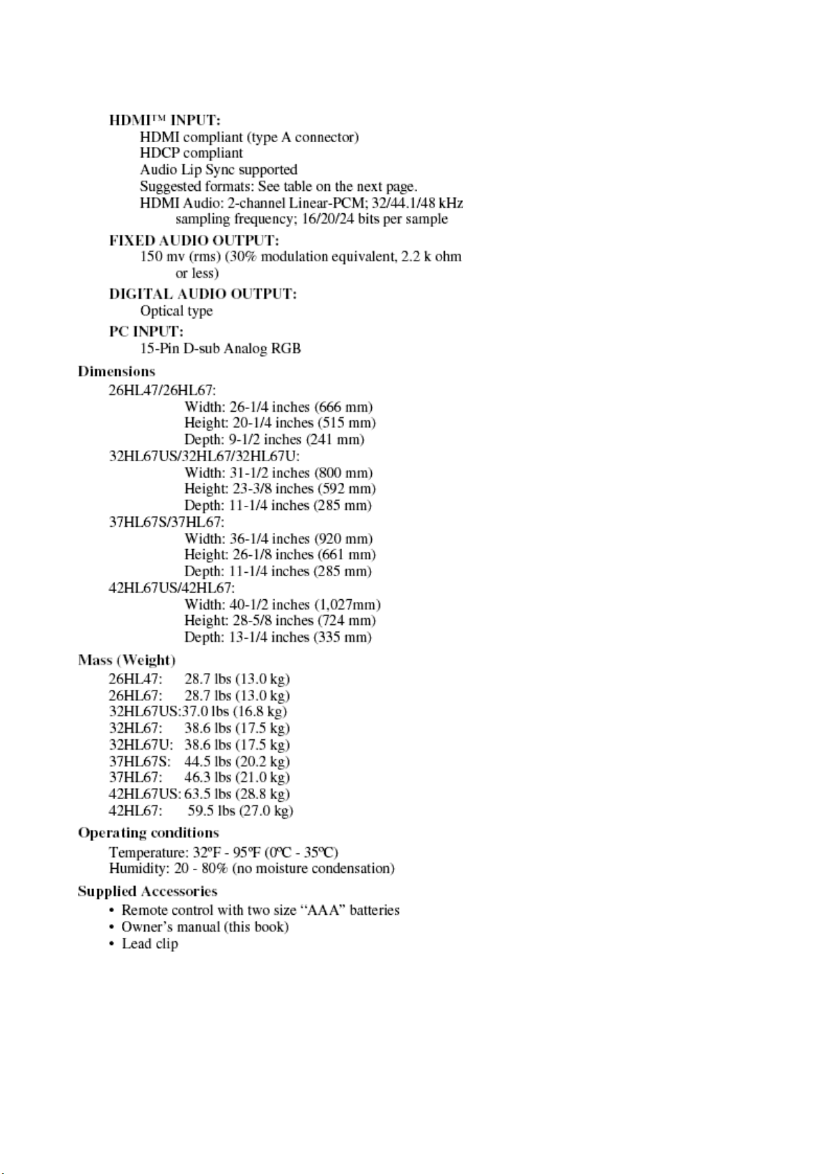
SPECIFICATION
Стр. 1 из
3
10.05.2015
file://C:\Documents and Settings\Alexsandr\Local Settings\Temp\Rar$EXa0.073\37H
...
Стр. 2 из
3
10.05.2015
file://C:\Documents and Settings\Alexsandr\Local Settings\Temp\Rar$EXa0.073\37H
...

Стр. 3 из
3
10.05.2015
file://C:\Documents and Settings\Alexsandr\Local Settings\Temp\Rar$EXa0.073\37H
...
 Loading...