

Toshiba 37HL17 Schematic
SERVICE MANUAL
(*1), as indicated by the underlined serial number.
Стр. 1 из
1
08.05.2015
file://D:\Documents and Settings\Admin\
Рабочий стол
\37HL17 Ver. 1.01\37HL17
-0...
LCD Color Television
37HL17
Ver. 1.01
This model is classified as a green product
This Service Manual describes replacement parts for the green product. When repairing this
green product, use the part(s) described in this manual and lead-free solder (*2).
For (*1) and (*2), refer to
SOLDER
© TOSHIBA CORPORATION
.
GREEN PRODUCT PROCUREMENT
and
LEAD-FREE

GREEN PRODUCT PROCUREMENT
Corporation recognizes environmental protection as a key management tasks, and is doing its
Стр. 1 из
1
08.05.2015
file://D:\Documents and Settings\Admin\
Рабочий стол
\37HL17 Ver. 1.01\37HL17
-0...
The EC is actively promoting the WEEE & RoHS Directives that define standards for
recycling and reuse of Waste Electrical and Electronic Equipment and for the Restriction of
the use of certain Hazardous Substances. From July 1, 2006, the RoHS Directive will
prohibit any marketing of new products containing the restricted substances.
Increasing attention is given to issues related to the global environmental. Toshiba
utmost to enhance and improve the quality and scope of its environmental activities. In line
with this, Toshiba proactively promotes Green Procurement, and seeks to purchase and use
products, parts and materials that have low environmental impacts.
Green procurement of parts is not only confined to manufacture. The same green parts used
in manufacture must also be used as replacement parts.

LEAD-FREE SOLDER
free solder must
free solder may result in damage to the component and or PCB being
Стр. 1 из
1
08.05.2015
file://D:\Documents and Settings\Admin\
Рабочий стол
\37HL17 Ver. 1.01\37HL17
-0...
This product is manufactured using lead-free solder as a part of a movement within the
consumer products industry at large to be environmentally responsible. Lead-
be used in the servicing and repair of this product.
WARNING: This product is manufactured using lead free solder.
DO NOT USE LEAD BASED SOLDER TO REPAIR THIS PRODUCT!
The melting temperature of lead-free solder is higher than that of leaded solder by 86ºF to
104ºF (30ºC to 40ºC). Use of a soldering iron designed for lead-based solders to repair
product made with lead-
soldered. Great care should be made to ensure high-quality soldering when servicing this
product especially when soldering large components, through-hole pins, and on PCBs as the
level of heat required to melt lead-free solder is high.
IMPORTANT NOTICE
Through WEB, ver. 6.5 has been released but with it, the linking function in this manual may
Стр. 1 из
2
08.05.2015
file://D:\Documents and Settings\Admin\
Рабочий стол
\37HL17 Ver. 1.01\37HL17
-0...
A Known Malfunction
Autodesk® DWF™ Viewer version
(Free software provided through WEB)
Use Autodesk DWF Viewer ver. 6.0.
not work properly.
If ver. 6.5 has been installed, uninstall it and reinstall ver. 6.0.
To get ver. 6.0, click the icon, or contact to the nearest Toshiba Service Centre for further
assistance.
Freezing windows opened
(Cannot close the open windows)
This may happen occasionally.
In case of encountering this, follow the procedure below.
1. Press [Ctrl], [Alt] and [Delete] keys at the same time to engage windows security
windows.
2. Then, choose TASK manager and Application tab, and select TOSHIBA SERVICE
MANUAL-Microsoft Internet Explorer.
3. Click TASK-end.
Main Window back forwarded
The real cause has not been found yet but with this condition, nothing disturbs the service
manual operation.

Continue to use by operating the windows.
Стр. 2 из
2
08.05.2015
file://D:\Documents and Settings\Admin\
Рабочий стол
\
37HL17 Ver. 1.01\37HL17
-0...
Precaution when opening the diagrams
While opening the diagrams, the menu in the left frame changes its color to GRAY. This is
an indication that the viewer is processing.
With this condition, the menu indication color may stick to the GRAY color or Windows
may freeze if clicking other menu.
To avoid such things, do not operate any others while menu turns GRAY color.
If entering this, re-open the service manual or refresh the left frame.
IMPORTANT NOTICE
Стр. 1 из
4
08.05.2015
file://D:\Documents and Settings\Admin\
Рабочий стол
\37HL17 Ver. 1.01\37HL17
-0...
User Guide
Autodesk® DWF™ Viewer
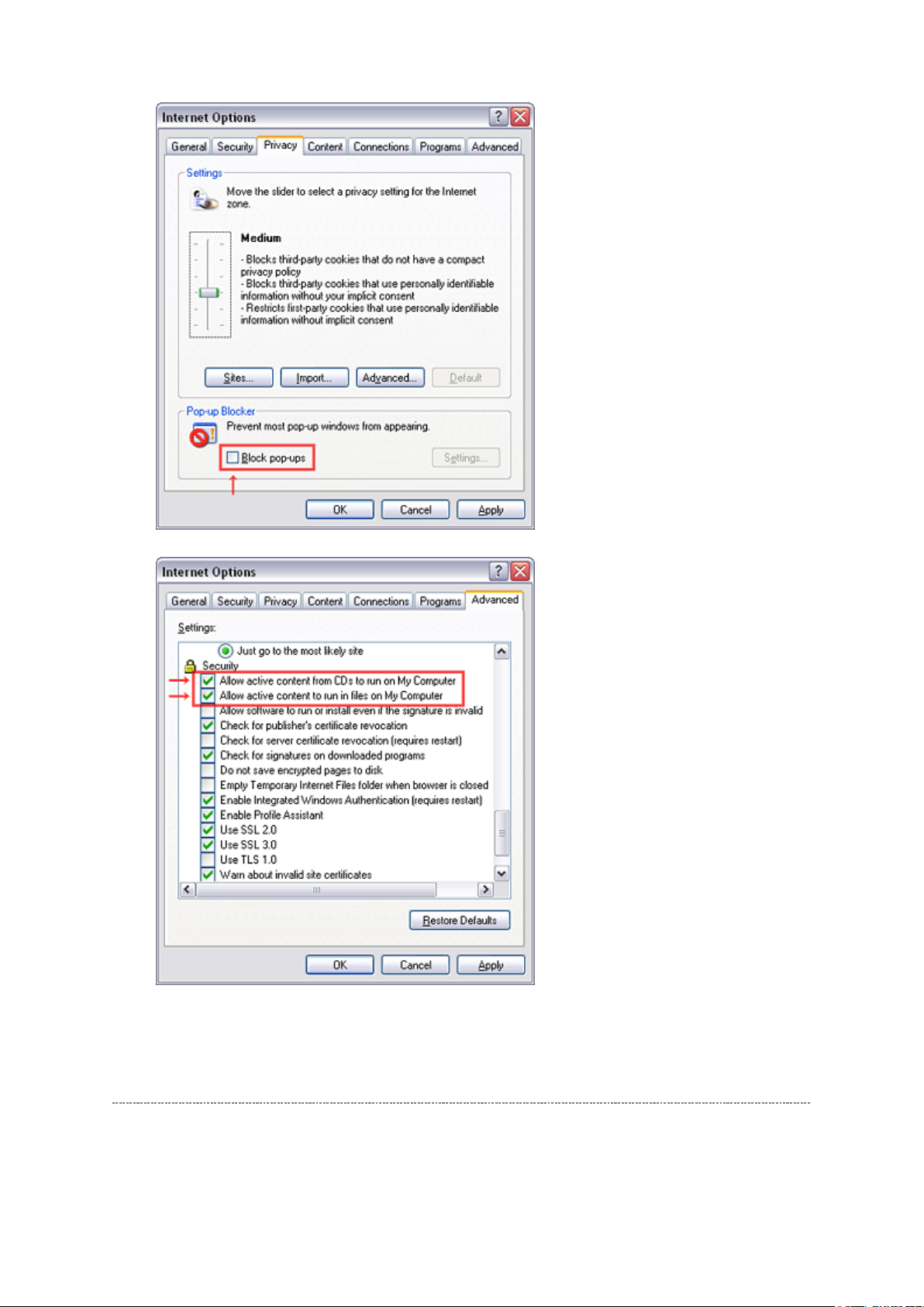
this system. Please download and install.
When
function and this sample may not work. In that case, perform the Internet Explorer setting
using the following procedure to restore normal operation.
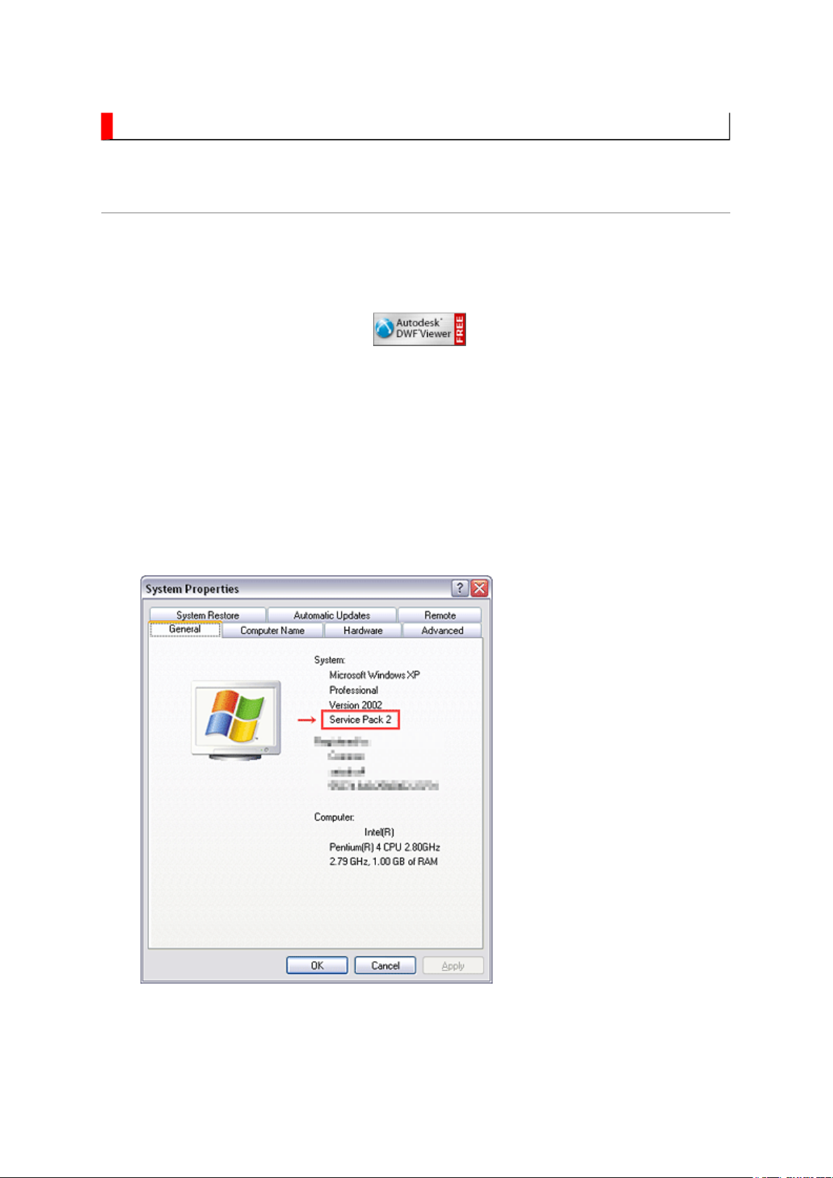
Windows XP SP2
1. Windows version check
[My Computer (right-click)] - [Properties]
is necessary to view drawings and to activate the functions of
is used, pop-up windows are limited by the enhanced security
2. Internet Explorer setting
[Tools] - [Internet Options]
Стр. 2 из
4
08.05.2015
file://D:\Documents and Settings\Admin\
Рабочий стол
\
37HL17 Ver. 1.01\37HL17
-0...
Operating Environment
PC : Pentium III or higher recommended
Monitor : 1024 x 768 or higher resolution recommended

Mouse : A mouse with wheel recommended
Стр. 3 из
4
08.05.2015
file://D:\Documents and Settings\Admin\
Рабочий стол
\
37HL17 Ver. 1.01\37HL17
-0...
OS : Microsoft Windows 2000/XP
Browser : Microsoft Internet Explorer 6.0 or later
Drawing viewer : Autodesk DWF Viewer 6.0
* Use the software following respective license terms and conditions.
Note:
In case of using this service manual with network connection, allocate its folder to the client
PCs as
network drive
to avoid any possible malfunction.
Or in case of accessing it through WEB site, the small pop-up window appears at the left
bottom corner on the screen whenever searching the location links. This is not malfunction.
Functions Provided on Each Drawing Page
Parts Information Reference Function
When the character string of a part on the drawing is clicked, its information is popped up at
the location. You can get any parts information immediately on the screen without referring
to the maintenance parts list.
Parts Search Function
You can search any part within the displayed drawing or within the whole schematic
diagram/board view by specifying a location number. The pop-up window displayed by
clicking a part's character string allows to search the part within the applicable schematic
diagram, board view or spare parts list.
A circle appears when the part is found, showing the part's location within the drawing.
Signal Line/Connector Destination Display Function
When a name at the end of a signal line in a divided schematic diagram is clicked, the
destination of the signal is searched and the display changes to the destination. Connecter
destinations can also be searched in the same way.
When two or more search results are provided, their drawing names are displayed, allowing
you to choose a desired drawing to display.

Layer Display Changing Function
When a pattern on a board view is clicked, it is highlighted in green. This allows easy pattern
Стр. 4 из
4
08.05.2015
file://D:\Documents and Settings\Admin\
Рабочий стол
\
37HL17 Ver. 1.01\37HL17
-0...
When any of the color buttons on the toolbar is clicked, it can be selected to display desired
layer in its color or not to display each layer. This allows you to see the pattern layer only by
setting other layers to "non-display".
PC Board View Pattern Highlighting Function
tracing.
Specified Area Printing Function
The Autodesk DWF Viewer enables to print the displayed drawing region as it is on a
printer. It also allows to print a large-sized drawing in multiple pieces (tile printing).
IMPORTANT NOTICE
Стр. 1 из
1
08.05.2015
file://D:\Documents and Settings\Admin\
Рабочий стол
\37HL17 Ver. 1.01\37HL17
-0...
WARNING:
You are requested that you shall not modify or alter the information or data
provided herein without prior written consent by Toshiba. Toshiba shall not
be liable to anybody for any damages, losses, expenses or costs, if any,
incurred in connection with or as a result of such modification or alteration.
THE INFORMATION OR DATA HEREIN SHALL BE PROVIDED "AS IS"
WITHOUT ANY WARRANTY OF ANY KIND, EITHER EXPRESS OR IMPLIED
WARRANTY OF MERCHANTABILITY AND FITNESS FOR A PARTICULAR
PURPOSE.
Toshiba shall not be liable for any damages, losses, expenses or costs, if
any, incurred in connection with or as a result of use of any information or
data provided herein.
ADJUSTMENT
While holding the MUTE button, press MENU
Стр. 1 из 8ADJUSTMENT [LCD] USA
08.05.2015
file://D:\Documents and Settings\Admin\
Рабочий стол
\37HL17 Ver. 1.01\37HL17
-0...
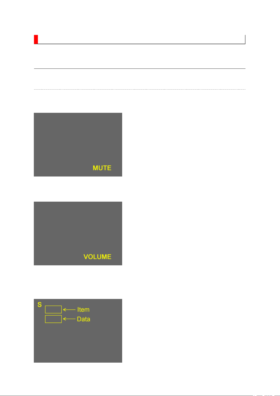
Service Mode
Entering to Service Mode
1. Set VOLUME to minimum and press MUTE
button twice on Control.
↓↓↓↓
↓↓↓↓
Service Mode display
2. Press MUTE button again and hold button
down.
3.
button on TV set.
Стр. 2 из 8ADJUSTMENT [LCD] USA
08.05.2015
file://D:\Documents and Settings\Admin\
Рабочий стол
\
37HL17 Ver. 1.01\37HL17
-0...
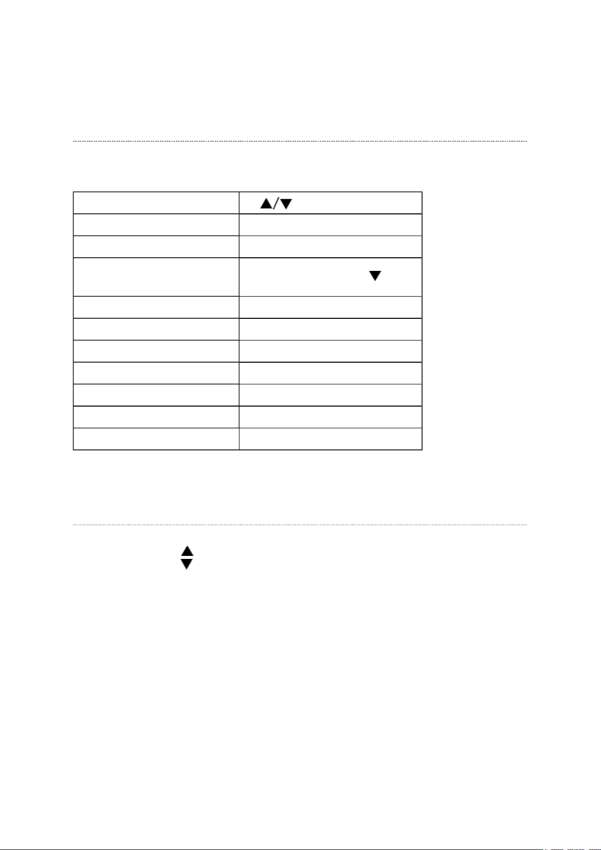
Key Function in the Service Mode
The following key entry during display of adjustment menu provides special functions.
Selection of the adjustment items CH (on TV or remote control)
Change of the data value Volume +/- (on TV or remote control)
Adjustment menu mode ON/OFF MENU button (on remote control)
Reset the count of operating
protect circuit to "00"
"RCUT" selection 1 button
"GCUT" selection 2 button
"BCUT" selection 3 button
"CNTX" selection 4 button
"COLC" selection 5 button
"UVTT" selection 6 button
Self diagnostic display ON/OFF 9 button
CALL + CH button on TV ( )
Selecting the Adjusting Item
Every pressing of CH button in the service mode changes the adjustment items in the
order of table below. ( button for reverse order)
SETTING & ADJUSTING DATA
[ SERVICE MODE ]
ADJUSTING ITEMS AND DATA IN THE SERVICE MODE:
Note:
(1) The image system data may be different for each image format chosen. The factory
preset data value is indicated in the table.
(a) HOST-MICRO EEPROM data
Prior to changing any board containing an EEPROM IC, the exisiting data in each image
Стр. 3 из 8ADJUSTMENT [LCD] USA
08.05.2015
file://D:\Documents and Settings\Admin\
Рабочий стол
\
37HL17 Ver. 1.01\37HL17
-0...
DRAMA0543 for HL series
(b) TV-MICRO EEPROM data
DRAMA0548 for HL series
(2)
format should be copied down as a precautionary measure.
Item Name of adjustment Data
HL series
R-CUT R CUTOFF 00H (a)
G-CUT G CUTOFF 00H (a)
B-CUT B CUTOFF 00H (a)
R-DRV R DRIVE 64H (a)
G-DRV G DRIVE 64H (a)
B-DRV B DRIVE 64H (a)
*BRTC BRIGHTNESS CENTER 78H (a)
*COLC COLOR CENTER C0H (a)
*UVTT BASE BAND TINT 80H (a)
*CNTX CONTRAST MAX FFH (a)
SHRC SHARPNESS CENTER 60H (a)
VBIS VBI Setting 64H (a)
CC Closed Caption 64H (a)
ID1 VBID 64H (a)
GG Gemstar 00H (a)
BYBK B-Y OFF SET 00H (a)
RYBK R-Y OFF SET 00H (a)
Стр. 4 из 8ADJUSTMENT [LCD] USA
08.05.2015
file://D:\Documents and Settings\Admin\
Рабочий стол
\
37HL17 Ver. 1.01\37HL17
-0...
OPT1 TV SET OPTION 1 00H (b)
OPT2 TV SET OPTION 2 25H (b)
OPT3 TV SET OPTION 3 00H (b)
OPT4 TV SET OPTION 4 25H (b)
OPT5 TV SET OPTION 5 01H (b)
SET-ID MODEL ID *1 (b)
MAGC AGC of MTS decoder 00H (b)
VO1 Volume1 Data 5FH (b)
V25 Volume25 Data ADH (b)
V50 Volume50 Data DFH (b)
V75 Volume75 Data F9H (b)
V100 Volume100 Data FFH (b)
VOLBS Correction Volume at DTV 00H (b)
VOLST Correction Volume at Stereo/SAP of ATV 00H (b)
EVOL Reduce Volume For Bassboost (Nonuse) 00H (b)
VOLX Volume Limiter For Hotel 64H (b)
BASX Bass Max Data 1AH (b)
TREX Treble Max Data 1AH (b)
TONN Tone Min Data 08H (b)
BASC Bass center Data 01H (b)
TREC Treble center Data 03H (b)
EBAS Add Bass on FOCUS 00H (b)
ETRE Add Treble on FOCUS 01H (b)
WON2 Bass Reducer 11H (b)
ALS ALS point 00H (b)
ALOF Reduce in ALL (wow, TruSurround) off 01H (b)
VSTB Reduce Volume For Stable Sound 00H (b)
VS3D Reduce Volume For SRS3D 01H (b)
VFCS Reduce Volume For FOCUS 03H (b)
VTBH Reduce Volume For TruBass High 00H (b)
VTBL Reduce Volume For TruBass Low 00H (b)
button will change the value of data in the range from 00H to
ID data according to panel
VVDD Reduce Volume For Dolby F3H (b)
Стр. 5 из 8ADJUSTMENT [LCD] USA
08.05.2015
file://D:\Documents and Settings\Admin\
Рабочий стол
\
37HL17 Ver. 1.01\37HL17
-0...
WFCS FOCUS Level 01H (b)
WWSP SRS 3D Level 02H (b)
WTBH TruBass High Level 03H (b)
WTBL TruBass Low Level 02H (b)
VOLM Volume coefficient at 1/2 Mute 32H (b)
Factory preset data will be loaded after setting Model ID data.
Note:
(*1) SET-ID data is subject to the models.
Refer to Setting Panel Option Data and SET-ID Data for detail.
Adjusting the Data
Pressing of VOLUME or
FFH. The variable range depends on the adjusting item.
Setting Panel Option Data and SET-ID Data
1. Panel option data is subject to OP4 and OP5.
Enter to service mode and select menu of OP4 or OP5 by pressing P or P during
Display of adjustment menu. After selecting OPT4 or OPT5, press + or - to set
OPT4 or OPT5 value as table below.
2. Whenever using new signal board to the set, setting the SET-
option data.
Set Size
HL67 26 SAMSUNG - 63h - 00h 01h A3h
32 SHARP SAMSUNG 25h 65h 00h 01h A4h
37 AUO SHARP 46h 26h 00h 01h A5h
42 LPL - 17h - 00h 01h A6h
HL37 32 SHARP SAMSUNG 25h 65h 00h 01h A4h
HL17 32 SHARP SAMSUNG 25h 65h 00h 01h A4h
Panel Maker OPT4
TOP Running change TOP Running change
OPT3 OPT5 SET-ID
37 AUO SHARP 46h 26h 00h 01h A5h
Стр. 6 из 8ADJUSTMENT [LCD] USA
08.05.2015
file://D:\Documents and Settings\Admin\
Рабочий стол
\
37HL17 Ver. 1.01\37HL17
-0...
42 LPL - 17h - 00h 01h A6h
Exit from Service Mode
Pressing POWER button to turn off the TV once.
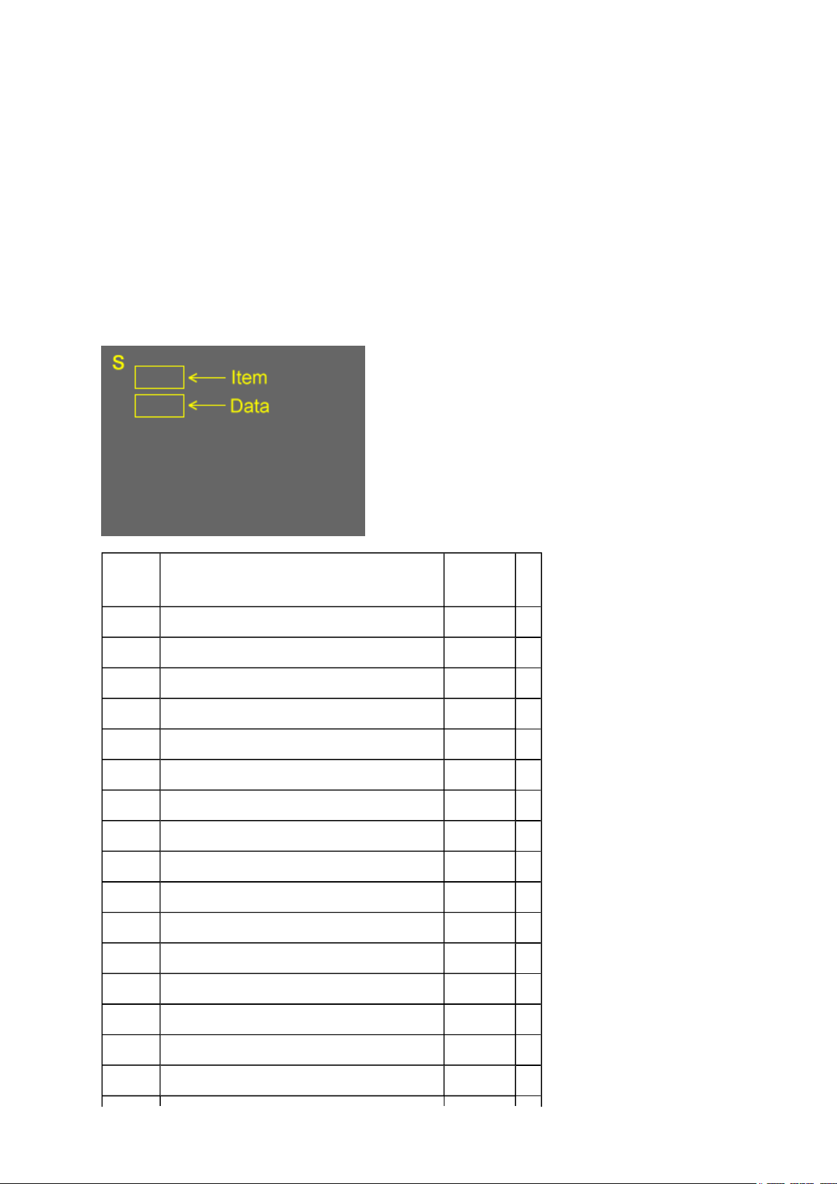
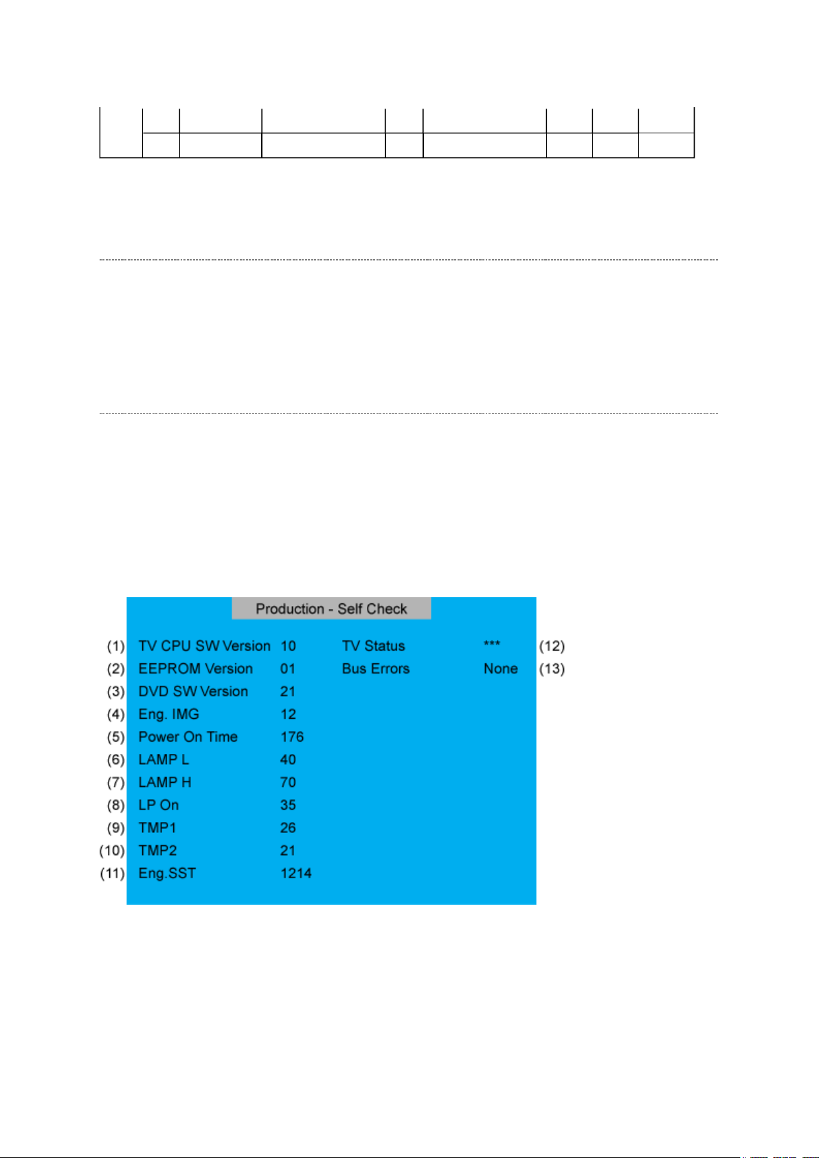
Self Diagnostic Function
1. Press "Recall" button on Remote Control during display of adjustment menu in the
service mode. This will bring up the "S" in the right corner of screen. Now press "9"
button on remote.
The diagnosis will begin to check if interface among IC's is executed properly.
2. During diagnosis, the following displays are shown.
(1) Version information of TV-MICRO : Display 1 byte data.
(2) Version information of TV-MICRO EEPROP : Display 1 byte data.
(3) Version information of DVD MPU : HL series not used.
(4) Revision of image file : LCD Model not used.
(5) Total brightness hour of TV. : Display 4 bytes data.
Стр. 7 из 8ADJUSTMENT [LCD] USA
08.05.2015
file://D:\Documents and Settings\Admin\
Рабочий стол
\
37HL17 Ver. 1.01\37HL17
-0...
(6) Operation hour of TV in LOW mode : Display 4 bytes data.
(7) Operation hour of TV in HIGH BRIGHT mode : LCD Model not used.
(8) Number of times of TV ON/OFF. : LCD Model not used.
(9) Temperature display of thermo-Sensor. (DMD) : LCD Model not used.
(10) Temperature display of thermo-Sensor. (LAMP) : LCD Model not used.
(11) DMD Engine System status : LCD Model not used.
(12) TV-MICRO System status : Not used
(13) IIC-BUS status
Bus line normal is "None" displayed.
When it is abnormal, the block name is displayed as follows.
"SCL-GND" (Red indication) : SCL-GND short circuit
"SDA-GND" (Red indication) : SDA-GND short circuit
"SCL-SDA" (Red indication) : SCL-SDA short circuit
"NG : MTS"
"NG : APRO"
"NG : AVSW"
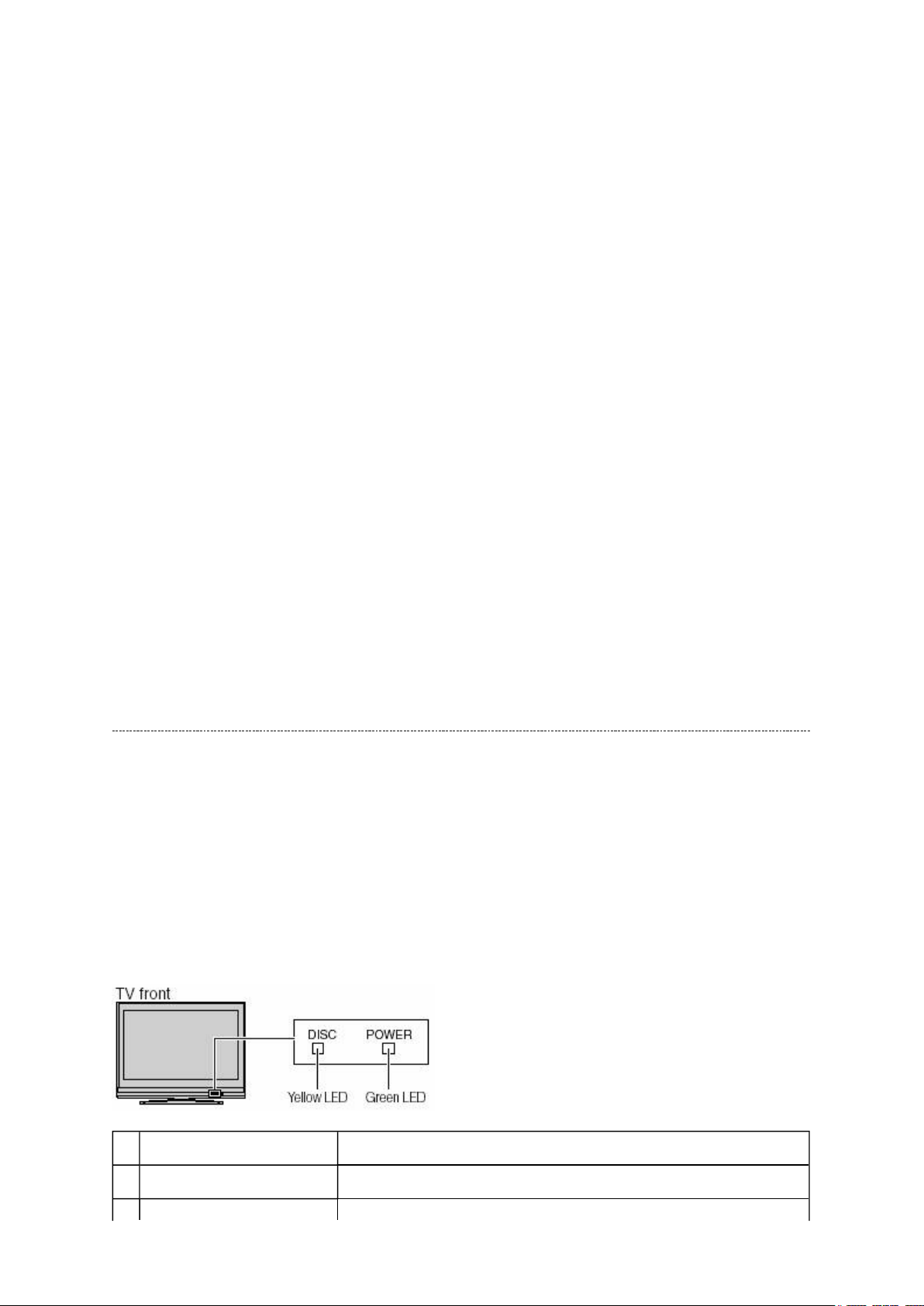
LED Indication
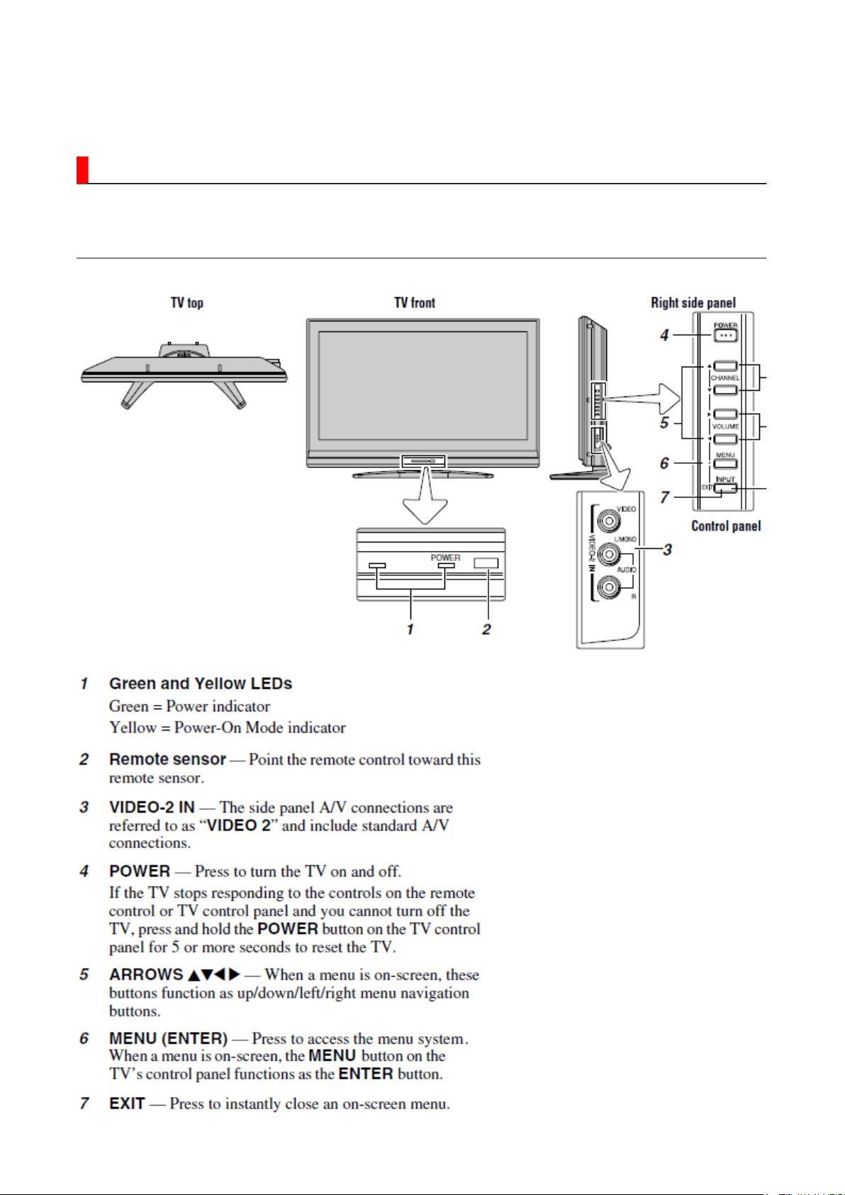
The yellow, blue and red/green LED lights on the TV (at the bottom center of the TV)
indicate the TV's status, as described below:
Note:
unplugged), when power is restored, the yellow LED will blink while the TV is booting until
the remote control is usable. This is normal and is not a sign of malfunction.
If the TV loses A/C power (e.g., a power outage occurs or the power cord is
LED Indication Condition
1 Green and Yellow are off. Power supply OFF. (AC)
2 Green and Yellow are off. Power supply OFF. (Stand by)
Стр. 8 из 8ADJUSTMENT [LCD] USA
08.05.2015
file://D:\Documents and Settings\Admin\
Рабочий стол
\
37HL17 Ver. 1.01\37HL17
-0...
3 Green is on (solid). The TV is operating properly.
4 Yellow is on (solid). Power-On Mode set into the quick operation.
The power is supplied to Digital Board only.
5 Green blinks. Fan stop detection.
6 Green blinks slowly. Abnormal operation of BUS line.
Turn the TV off and unplug the power cord, then plug the
power cord in again and turn the TV on.
7 Green blinks quickly. Power Protection Detection.
Turn the TV off and unplug the power cord, then plug the
power cord in again and turn the TV on.
8 Yellew blinks 3 times. The TV is rebooting.
Wait several seconds until the yellow LED stops blinking.
9 Green is on (solid).
Yellow is on (solid).
10 Green is on (solid).
Yellow is off.
11 Green is off.
Yellow is on (solid).
Upgrading in progress.
Upgrading succesful.
Upgrading failed.
FUNCTION AND OPERATION
Стр. 1 из
2
08.05.2015
file://D:\Documents and Settings\Admin\
Рабочий стол
\37HL17 Ver. 1.01\37HL17
-0...
TV Front and Side Panel Control and Connection
Стр. 2 из
2
08.05.2015
file://D:\Documents and Settings\Admin\
Рабочий стол
\
37HL17 Ver. 1.01\37HL17
-0...

FUNCTION AND OPERATION
Стр. 1 из
3
08.05.2015
file://D:\Documents and Settings\Admin\
Рабочий стол
\37HL17 Ver. 1.01\37HL17
-0...
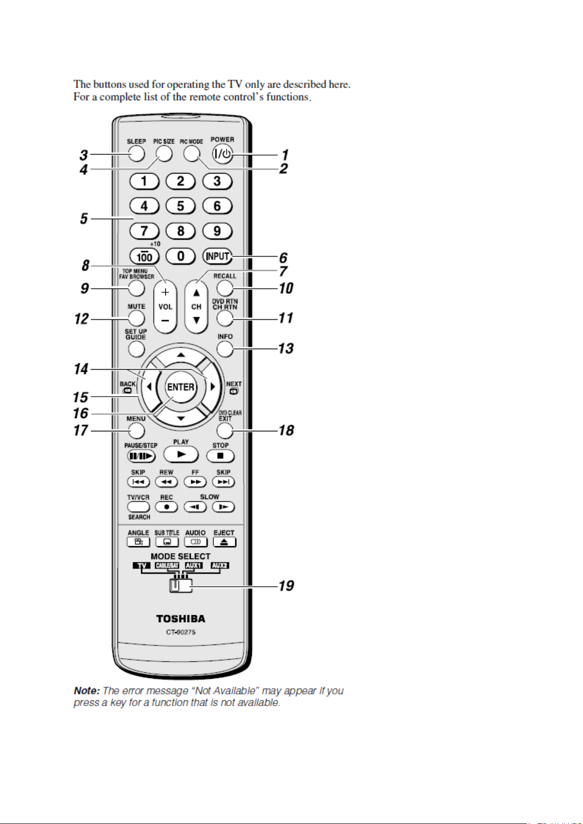
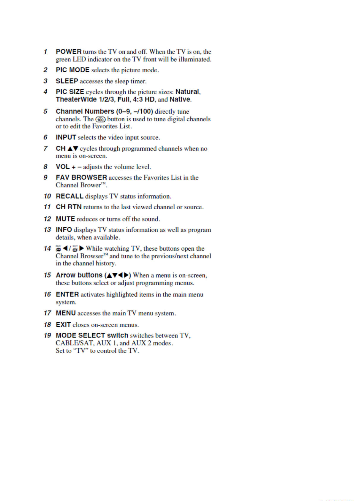
Learning about the Remote Control
Стр. 2 из
3
08.05.2015
file://D:\Documents and Settings\Admin\
Рабочий стол
\
37HL17 Ver. 1.01\37HL17
-0...
Стр. 3 из
3
08.05.2015
file://D:\Documents and Settings\Admin\
Рабочий стол
\
37HL17 Ver. 1.01\37HL17
-0...
FUNCTION AND OPERATION
Стр. 1 из
5
08.05.2015
file://D:\Documents and Settings\Admin\
Рабочий стол
\37HL17 Ver. 1.01\37HL17
-0...
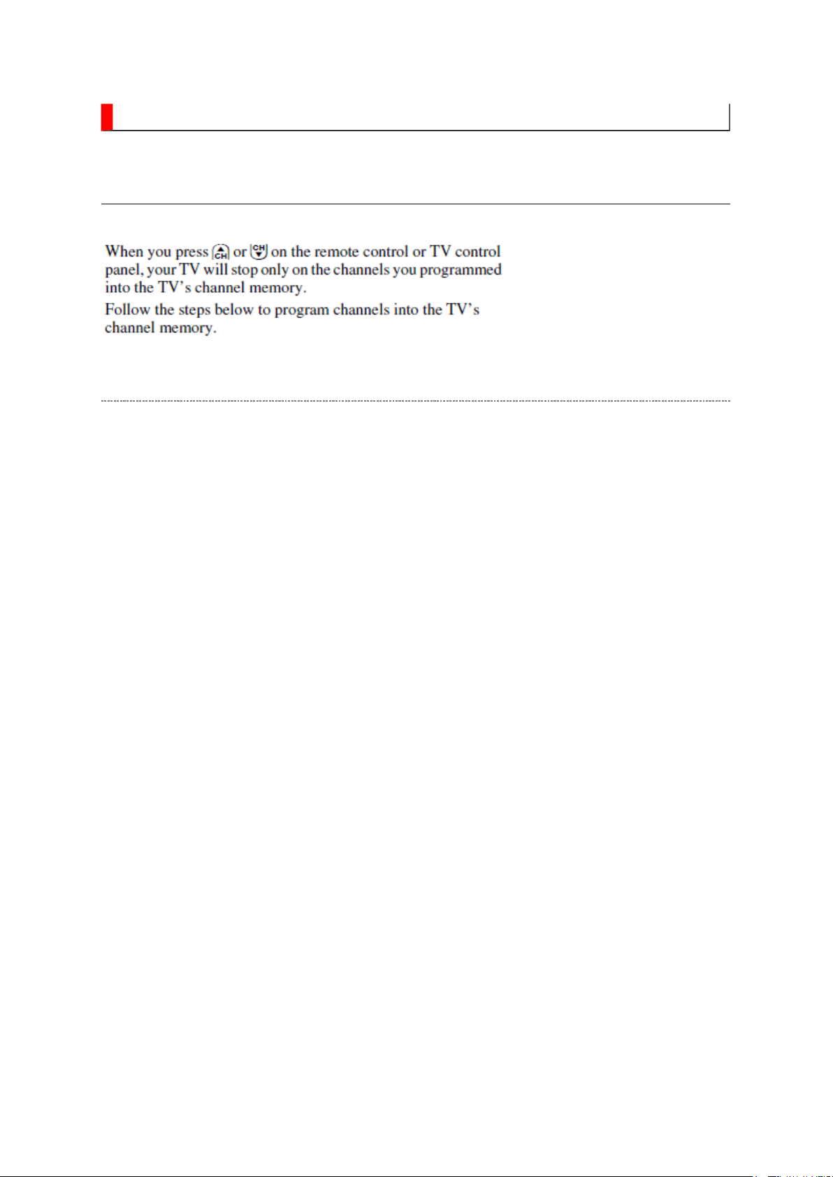
Programming Channel into the TV's Channel Memory
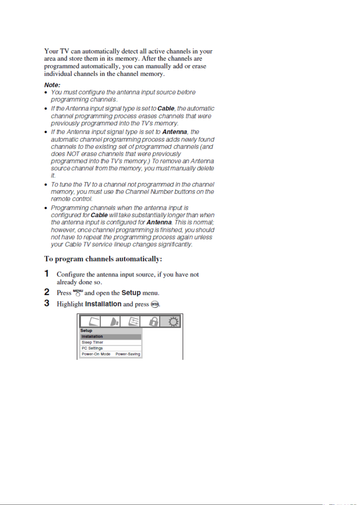
Programming Channel Automatically
Стр. 2 из
5
08.05.2015
file://D:\Documents and Settings\Admin\
Рабочий стол
\
37HL17 Ver. 1.01\37HL17
-0...
Стр. 3 из
5
08.05.2015
file://D:\Documents and Settings\Admin\
Рабочий стол
\
37HL17 Ver. 1.01\37HL17
-0...
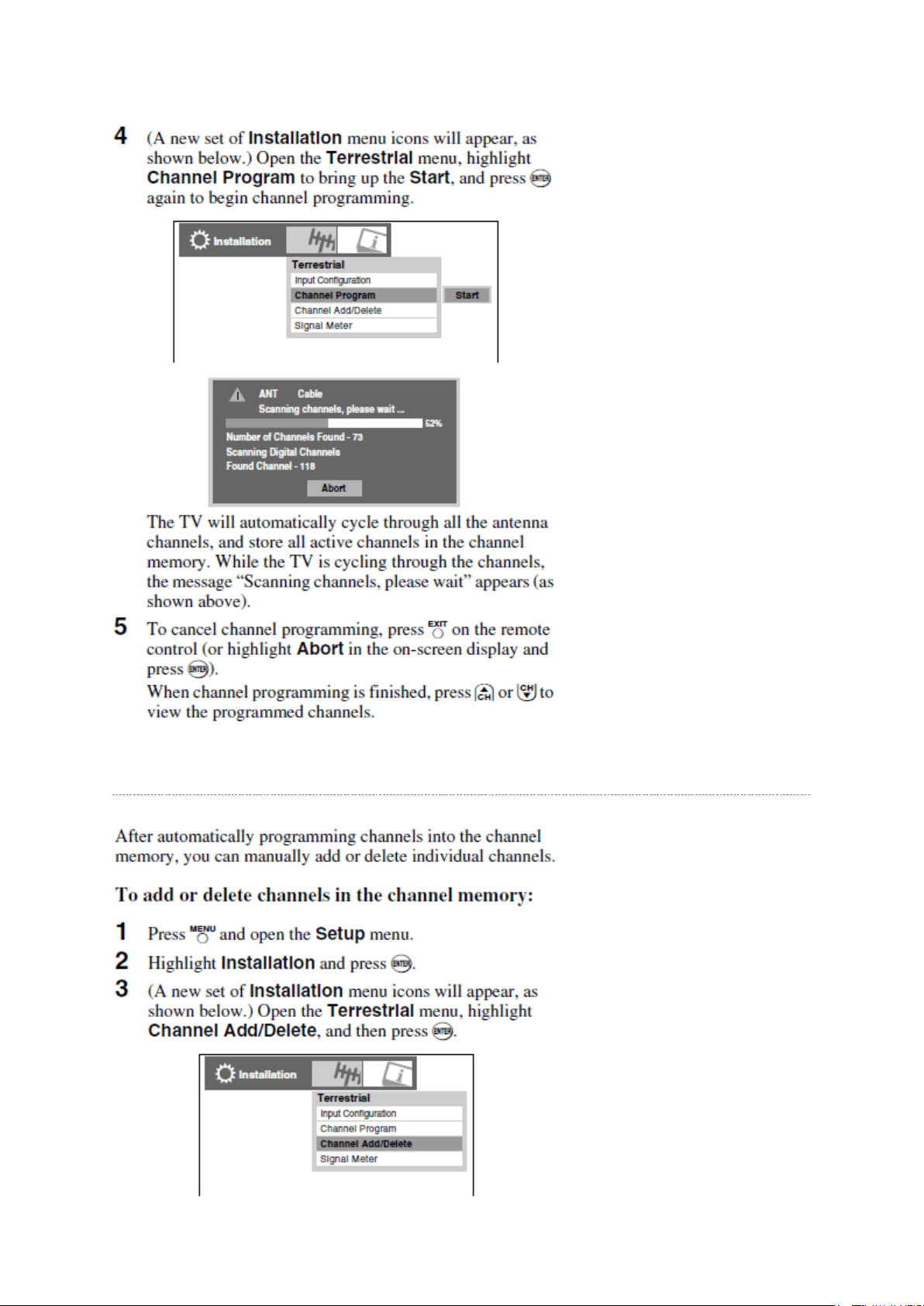
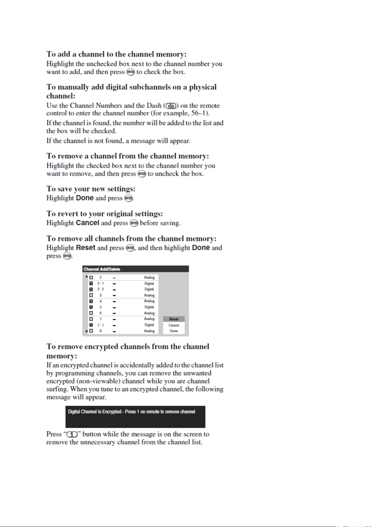
Manually Adding and Deleting Channel in the Channel Memory
Стр. 4 из
5
08.05.2015
file://D:\Documents and Settings\Admin\
Рабочий стол
\
37HL17 Ver. 1.01\37HL17
-0...

Стр. 5 из
5
08.05.2015
file://D:\Documents and Settings\Admin\
Рабочий стол
\
37HL17 Ver. 1.01\37HL17
-0...

SAFETY INSTRUCTION
should enter the mouth, rinse the mouth thoroughly with water. If the fluid should contact the
When attaching the LCD module to the LCD cover, position it appropriately and fasten
Стр. 1 из 4Handling the LCD Module
08.05.2015
file://D:\Documents and Settings\Admin\
Рабочий стол
\37HL17 Ver. 1.01\37HL17
-0...
Handling the LCD Module
Safety Precaution
In the event that the screen is damaged or the liquid crystal (fluid) leaks, do not breathe in or
drink this fluid.
Also, never touch this fluid. Such actions could cause toxicity or skin irritation. If this fluid
skin or clothing, wipe off with alcohol, etc., and rinse thoroughly with water. If the fluid
should enter the eyes, immediately rinse the eyes thoroughly with running water.
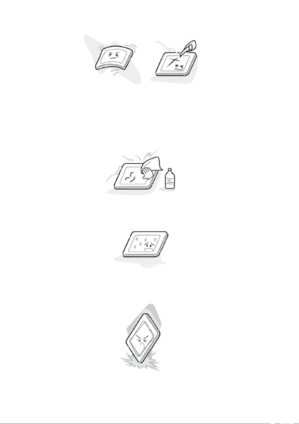
Precautions for Handling the LCD Module
CAUTION: The metal edges of the LCD module are sharp, handle it with
care.
The LCD module can easily be damaged during disassembly or reassembly; therefore,
always observe the following precautions when handling the module.
1.
at the position where the display can be viewed most conveniently.
2. Carefully align the holes at all four corners of the LCD module with the corresponding
holes in the LCD cover and fasten with screws. Do not strongly push on the module
because any impact can adversely affect the performance. Also use caution when
handling the polarized screen because it can easily be damaged.
Стр. 2 из 4Handling the LCD Module
08.05.2015
file://D:\Documents and Settings\Admin\
Рабочий стол
\
37HL17 Ver. 1.01\37HL17
-0...
3. If the panel surface becomes soiled, wipe with cotton or a soft cloth. If this does not
remove the soiling, breathe on the surface and then wipe again.
If the panel surface is extremely solied, use a CRT cleaner as a cleaner. Wipe off the
panel surface by drop the cleaner on the cloth. Do not drop the cleaner on the panel.
Pay attention not to scratch the panel surface.
4. Leaving water or other fluids on the panel screen for an extended period of time can
result in discoloration or stripes. Immediately remove any type of fluid from the screen.
5. Glass is used in the panel, so do not drop or strike with hard objects. Such actions can
damage the panel.
 Loading...