

Page 1
Introduction
your TV
Connecting
O
WNER'S
M
ANUAL
Color Television
Using the
Remote Control
your TV
Setting up
32HFX73
36HFX73
S
U
N
M
O
C
E
A
C
I
R
E
M
A
A
B
I
H
S
O
T
I
S
O
1
4
0
0
R
P
R
O
D
U
C
T
S
,
I
N
C
.
5
4
6
9
A
.
1
o
N
F
E
I
L
Owner's Record
The model number and serial number are on the back
of your TV. Record these numbers in the spaces below.
Refer to these numbers whenever you communicate
with your Toshiba dealer about this TV.
Model number:
Serial number:
23566004
Features
Using the TV’s
Appendix
Index
Page 2
Dear Customer,
Thank you for purchasing this Toshiba TV. This manual will
help you use the many exciting features of your new TV.
Before operating the TV, please read this manual
completely, and keep it nearby for future reference.
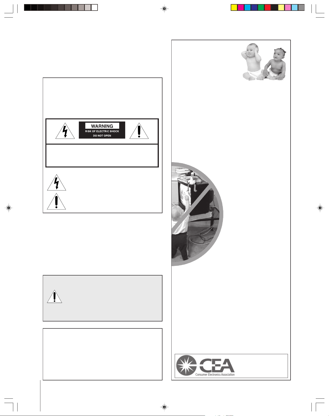
Child Safety
It Makes A Difference
Where Your TV Stands
Safety Precautions
WARNING
TO REDUCE THE RISK OF FIRE OR ELECTRIC SHOCK,
DO NOT EXPOSE THIS APPLIANCE TO RAIN OR
MOISTURE.
WARNING: TO REDUCE THE RISK OF ELECTRIC
SHOCK, DO NOT REMOVE COVER (OR BACK).
NO USER-SERVICEABLE PARTS INSIDE. REFER
SERVICING TO QUALIFIED SERVICE PERSONNEL.
The lightning symbol in the triangle tells you that the
voltage inside this product may be strong enough to
cause an electric shock. DO NOT TRY TO SERVICE
THIS PRODUCT YOURSELF.
The exclamation mark in the triangle tells you that
important operating and maintenance instructions
follow this symbol.
NOTE TO CATV INSTALLERS IN THE USA
This is a reminder to call the CATV system installer’s
attention to Article 820-40 of the NEC, which provides
guidelines for proper grounding and, in particular, specifies
that the cable ground shall be connected to the grounding
system of the building, as close to the point of cable entry
as practical. For additional antenna grounding information,
see items 25 and 26 on page 4.
NOTICE OF POSSIBLE TV STAND INSTABILITY
DANGER: RISK OF SERIOUS PERSONAL
INJURY OR DEATH!
the TOSHIBA TV stand recommended in the
“Specifications” section only.
result in instability, causing possible injury or death.
NOTICE OF POSSIBLE ADVERSE EFFECTS
ON TV PICTURE TUBE
If a fixed (non-moving) pattern remains on the TV
screen for long periods of time, the image can become
permanently engrained in the picture tube. This type of
damage is NOT COVERED BY YOUR WARRANTY.
See item 33 on page 4.
Use this TV with
Use with other stands may
Congratulations on your purchase! As you enjoy
your new TV, keep these safety tips in mind:
The Issue
If you are like most consumers, you have a TV in your home.
Many homes, in fact, have more than one TV.
The home theater entertainment experience is a growing
trend, and larger TVs are popular purchases; however, they
are not always supported on the proper TV stands.
Sometimes TVs are improperly secured or inappropriately
situated on dressers, bookcases, shelves, desks, audio
speakers, chests, or carts. As a result, TVs may fall over,
causing unnecessary injury.
Toshiba Cares!
The consumer electronics industry
is committed to making home
entertainment enjoyable and safe.
The Consumer Electronics
Association formed the Home
Entertainment Support Safety
Committee, comprised of TV and
consumer electronics furniture
manufacturers, to advocate
children’s safety and educate
consumers and their families about
television safety.
Tune Into Safety
One size does NOT fit all! Use appropriate
furniture large enough to support the weight of your
TV (and other electronic components).
Use appropriate angle braces, straps, and anchors to secure
your furniture to the wall (but never screw anything directly
into the TV).
Carefully read and understand the other enclosed
instructions for proper use of this product.
Do not allow children to climb on or play with furniture
and TVs.
Avoid placing any item on top of your TV (such as a VCR,
remote control, or toy) that a curious child may reach for.
Remember that children can become excited while watching
a program and can potentially push or pull a TV over.
Share our safety message about this hidden hazard of
home with your family and friends. Thank you!
2500 Wilson Blvd.
Arlington, VA 22201 U.S.A.
Tel. 703-907-7600 Fax 703-907-7690
www.CE.org
CEA is the Sponsor, Producer and
Manager of the International CES
the
®
2 0303
Page 3
Important Safety Instructions
QUALIFIED
SERVICE
TECHNICIAN
Installation, Care, and Service
1) Read these instructions.
2) Keep these instructions.
3) Heed all warnings.
4) Follow all instructions.
5) Do not use this apparatus near
water.
6) Clean only with a dry cloth.
7) Do not block any ventilation
openings. Install in accordance with
the manufacturer’s instructions.
8) Do not install near any heat
sources such as radiators,
heat registers, stoves, or other
apparatus (including amplifiers)
that produce heat.
9) Do not defeat the safety purpose of the polarized or
grounding type plug. A polarized plug has two blades
with one wider than the other. A grounding type plug has
two blades and a third grounding
prong. The wide blade or the third
prong are provided for your safety.
If the provided plug does not fit into
your outlet, consult an electrician
for replacement of the obsolete outlet.
Wide plug
Installation
Follow these recommendations and precautions and heed all
warnings when installing your TV:
16) Never modify this equipment. Changes or modifications
may void: a) the warranty, and b) the user’s authority to
operate this equipment under the rules of the Federal
Communications Commission.
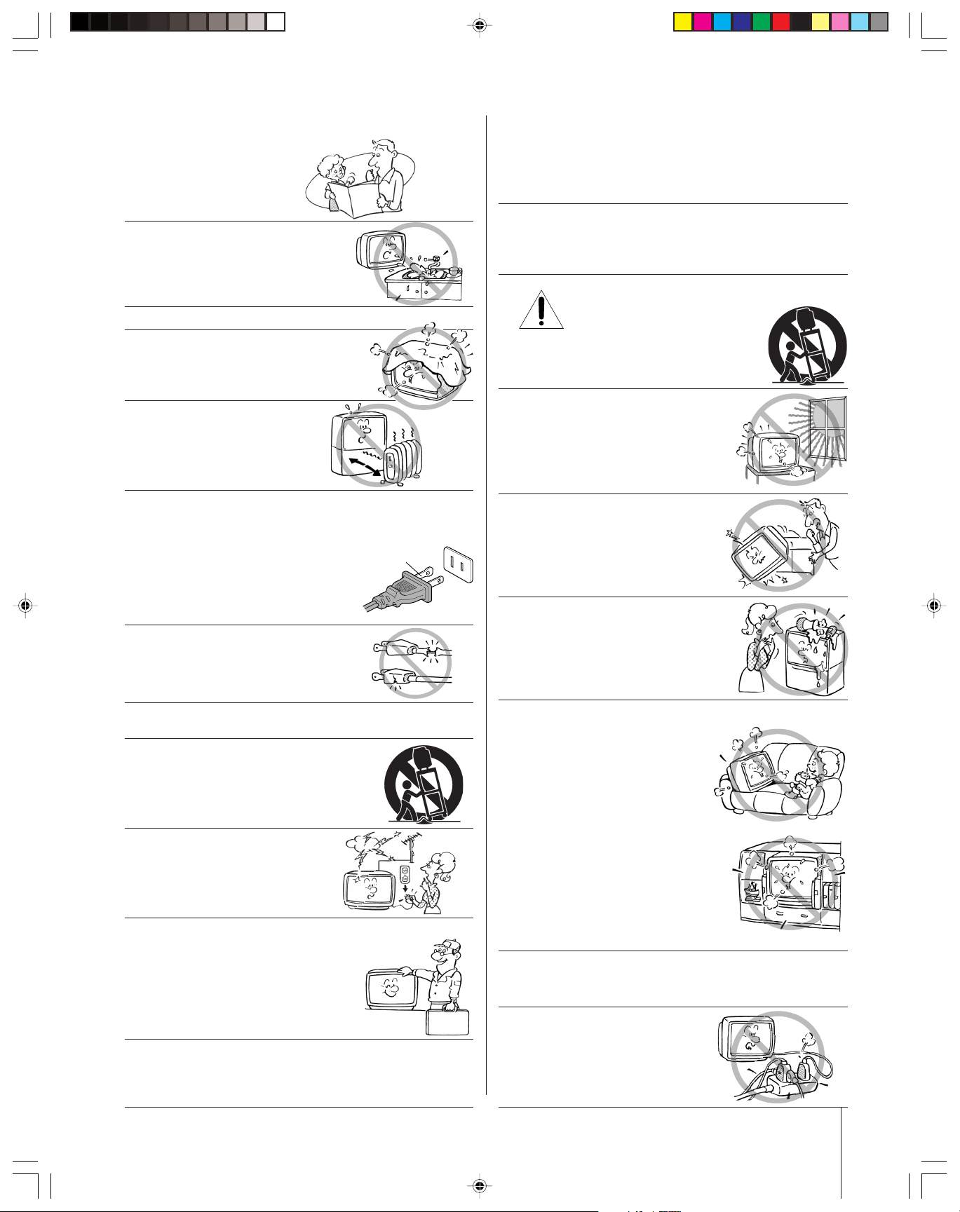
17) DANGER: RISK OF SERIOUS PERSONAL
INJURY, DEATH, OR EQUIPMENT
DAMAGE! Never place the TV on
an unstable cart, stand, or table. The TV
may fall, causing serious personal injury,
death, or serious damage to the TV.
18) Never place or store the TV in direct
sunlight; hot, humid areas; areas
subject to excessive dust or vibration;
or locations with temperatures at or
below 41°F (5°C).
19) Always place the TV on the floor
or a sturdy, level, stable surface that
can support the weight of the unit.
10) Protect the power cord from being
walked on or pinched, particularly at
plugs, convenience receptacles, and
the point where it exits the apparatus.
11) Only use attachments/accessories specified by the
manufacturer.
12) Use only with the cart, stand, tripod,
bracket, or table specified by the
manufacturer, or sold with the
apparatus. When a cart is used, use
caution when moving the cart/apparatus
combination to avoid injury from tip-over.
13) Unplug this apparatus during
lightning storms or when
unused for long periods
of time.
14) Refer all servicing to qualified service personnel.
Servicing is required when the apparatus has been
damaged in any way, such as power supply
cord or plug is damaged, liquid has
been spilled or objects have fallen into
the apparatus, the apparatus has been
exposed to rain or moisture, does not
operate normally, or has been dropped.
15) CAUTION: To reduce the risk of electric shock, do not
use the polarized plug with an extension cord, receptacle,
or other outlet unless the blades can be inserted
completely to prevent blade exposure.
20) Never place items such as vases,
aquariums, or candles on top of the TV.
21) Never block or cover the slots or
openings in the TV cabinet back,
bottom, and sides. Never place
the TV:
• on a bed, sofa, rug, or similar
surface;
• too close to drapes, curtains,
or walls; or
• in a confined space such as a
bookcase, built-in cabinet, or any
other place with poor ventilation.
The slots and openings are provided
to protect the TV from overheating
and to help maintain reliable
operation of the TV.
22) Never allow anything to rest on or roll over the power
cord, and never place the TV where the power cord is
subject to wear or abuse.
23) Never overload wall outlets and
extension cords.
0303 3
Page 4
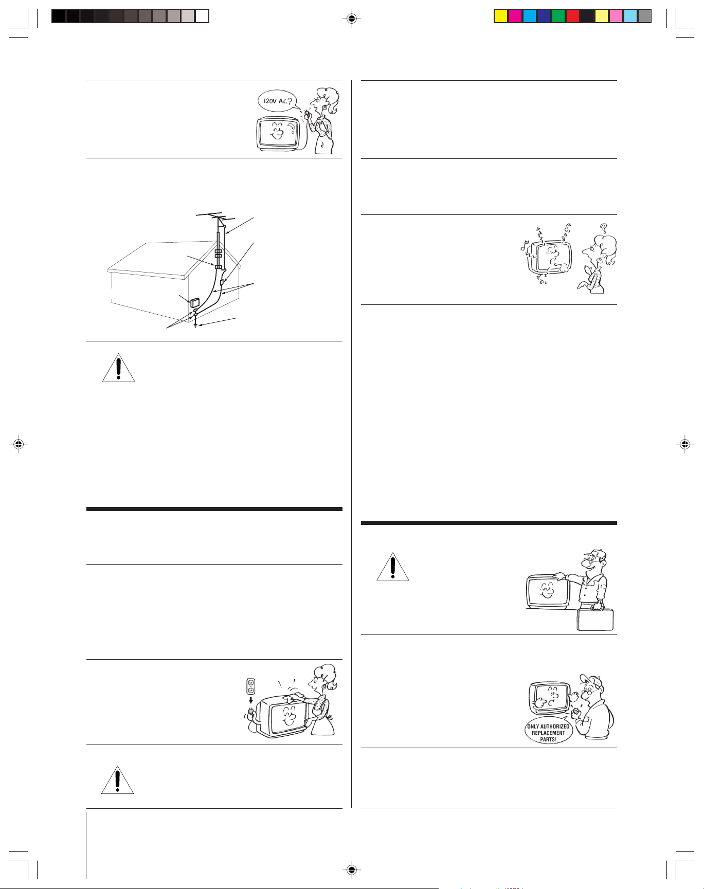
Ground clamp
Antenna discharge unit
(NEC Section 810-20)
Grounding conductors
(NEC Section 810-21)
Power service grounding
electrode system (NEC Art 250 Part H)
Ground clamps
Antenna lead-in wire
Electric service equipment
24) Always operate this equipment from
a 120 VAC, 60 Hz power source only.
30) [This item applies to projection TVs only.] If the air
temperature rises suddenly (for example, when the TV is
first delivered), condensation may form on the lenses. This
can make the picture appear distorted or the color appear
faded. If this happens, turn off the TV for 6 to 7 hours to
allow the condensation to evaporate.
25) Always make sure the antenna system is properly
grounded to provide adequate protection against voltage
surges and built-up static charges (see Section 810 of the
National Electric Code).
26) DANGER: RISK OF SERIOUS PERSONAL
INJURY OR DEATH!
• Use extreme care to make sure you are never in
a position where your body (or any item you are in contact
with, such as a ladder or screwdriver) can accidentally
touch overhead power lines. Never locate the antenna
near overhead power lines or other electrical circuits.
• Never attempt to install any of the following during
lightning activity:
a) an antenna system; or b) cables, wires, or any home
theater component connected to an antenna or phone
system.
31)For added protection of your TV from lightning and power
surges, always unplug the power cord and disconnect the
antenna from the TV if you leave the TV unattended or
unused for long periods of time.
32) During normal use, the TV may make
occasional snapping or popping
sounds. This is normal, especially
when the unit is being turned on or
off. If these sounds become frequent
or continuous, unplug the power cord
and contact a Toshiba Authorized Service Center.
33) Possible Adverse Effects on TV Picture Tube: If a fixed
(non-moving) pattern remains on the TV screen for long
periods of time, the image can become permanently
engrained in the picture tube and cause subtle but
permanent ghost images. This type of damage is NOT
COVERED BY YOUR WARRANTY. Never leave your TV
on for long periods of time while it is displaying the
following formats or images:
• Fixed Images, such as PIP/POP windows, stock tickers,
video game patterns, TV station logos, and websites.
• Special Formats that do not use the entire screen. For
example, viewing letterbox style (16:9) media on a
normal (4:3) display (gray bars at top and bottom of
screen); or viewing normal style (4:3) media on a
widescreen (16:9) display (gray bars on left and right
sides of screen).
Care
For better performance and safer operation of your TOSHIBA
TV, follow these recommendations and precautions:
27) Always sit approximately 10–25 feet away from the TV and
as directly in front of it as possible. The picture can appear
dull if you sit too far to the left or right of the TV, or if
sunlight or room lights reflect on the screen. Turn the TV
off to check for reflections on the screen, and then remove
the source of reflections while viewing the TV.
28) Always unplug the TV before
cleaning. Never use liquid or
aerosol cleaners.
29) WARNI NG: RISK OF ELECTRIC SHOCK!
4 0303
Never spill liquids or push objects of any kind
into the TV cabinet slots.
Service
34) WARNING: RISK OF ELECTRIC
SHOCK! Never attempt to service the
TV yourself. Opening and
removing the covers may expose
you to dangerous voltage or other
hazards. Refer all servicing to a
Toshiba Authorized Service Center.
35) If you have the TV serviced:
• Ask the service technician to use only replacement parts
specified by the manufacturer.
• Upon completion of service, ask
the service technician to perform
routine safety checks to determine
that the TV is in safe operating
condition.
36)When the TV reaches the end of its useful life, ask a
qualified service technician to properly dispose of the TV.
Improper disposal may result in a picture tube implosion
and possible personal injury.
Page 5

Important Safety Information ............................. 2-4
Introduction................................................................ 6
Welcome to Toshiba......................................................... 6
Exploring your new TV ................................................... 6
Note regarding Quick Connect Guide ........................ 6
Connecting your TV .................................................. 7
Connecting a VCR .......................................................... 7
Connecting a cable box ....................................................8
Connecting a cable box and VCR .................................... 8
Connecting a DVD player or satellite receiver and a VCR 9
Connecting a DVD player with component video
and a VCR ..................................................................... 10
Connecting a DTV receiver/set-top box with
component video and a VCR ......................................... 11
Connecting two VCRs ................................................... 12
Connecting a camcorder ................................................ 12
Connecting a device to the DVI/HDCP input .............. 13
Connecting an audio system .......................................... 14
Connecting an A/V receiver ........................................... 14
Using the remote control ...................................... 15
Preparing the remote control for use .............................. 15
Installing the remote control batteries ............................ 15
Remote Control functional key chart ...................... 16
Programming the remote control for use with
your audio/video devices ................................................ 18
Device code setup ................................................... 18
Searching and sampling the code of a device (8500) ....
Using the volume lock feature (8000) ..................... 19
Operational feature reset (8900) ............................. 19
Device code table ...............................................20-21
Learning about the remote control .......................... 22
18
Setting up your TV .................................................. 23
Learning about the menu system ................................... 23
Using the Quick Connect Guide ................................... 24
Changing the on-screen display language ....................... 24
Selecting the antenna input ............................................ 25
Adding channels to the TV’s memory ............................ 25
Programming channels automatically ...................... 25
Adding and erasing channels manually.................... 26
Changing channels ........................................................ 27
Changing channels using SpeedSurf........................ 27
Adjusting the tilt correction feature................................ 27
Using the TV’s features.......................................... 28
Adjusting the channel settings ........................................ 28
Switching between two channels using
Channel Return ...................................................... 28
Switching between two channels using SurfLock™ ....
Programming your favorite channels ....................... 28
Labeling channels ................................................... 30
Viewing the wide-screen picture formats ........................ 31
Selecting the image shape ........................................ 31
Using the auto aspect feature .................................. 33
Selecting the cinema mode ...................................... 33
Using the POP double-window feature .......................... 34
Switching the main and POP pictures..................... 35
Freezing the POP picture ........................................ 35
Adjusting the size of the double-window................. 35
Double-Window aspect ratio .................................. 36
28
Using the programmed channel search function............. 36
Using the favorite channel search function .............. 37
About the auto favorite feature................................ 37
Using the LOCKS menu ............................................... 38
Entering the PIN code ............................................ 38
If you cannot remember your PIN code .................. 38
Using the V-CHIP menu ............................................... 39
ENABLE BLOCKING .......................................... 39
TV RATING (Independent rating system for
broadcasters) ........................................................... 39
MPAA RATING (Independent rating system for
movies) ................................................................... 40
BLOCKING OPTION .......................................... 40
Unlocking programs temporarily ............................ 41
Locking channels ........................................................... 41
Locking video inputs ..................................................... 42
Using the game timer ..................................................... 43
Using the front panel lock feature .................................. 43
Changing the PIN code ................................................. 43
Adjusting the picture ..................................................... 44
Selecting the picture mode ...................................... 44
Adjusting the picture quality ................................... 44
Saving new preference ............................................. 45
Using the flesh tone feature..................................... 45
Using the CableClear™ DNR feature .................... 45
Selecting the color temperature ............................... 46
Resetting picture adjustments ................................. 46
Selecting the Scan Velocity Modulation (SVM) ...... 47
Selecting the display format (for 480p signals only) 47
Selecting the video input source ..................................... 48
Labeling the video input sources .................................... 48
Using the closed caption feature..................................... 49
Setting the ON-timer .................................................... 50
Setting the sleep timer.................................................... 50
Setting the clock ............................................................ 51
Selecting the background of the menu display ............... 51
Adjusting the sound ....................................................... 52
Muting the sound ................................................... 52
Selecting stereo/SAP broadcasts .............................. 52
Enjoying the Dolby Virtual sound feature............... 53
Using the WOW™ surround sound feature ........... 54
Adjusting the sound quality .................................... 54
Resetting your audio adjustments ........................... 55
Using the CYCLONE
Turning off the built-in speakers ............................. 56
Selecting the Audio OUT sound ............................. 56
Using the StableSound
Displaying on-screen information .................................. 57
Viewing the demo mode ................................................ 58
Understanding the auto power off feature ...................... 58
Understanding the last mode memory feature ................ 58
®
sub-woofer system ............. 55
®
feature .............................. 57
Appendix ................................................................... 59
Specifications ................................................................. 59
Tr oubleshooting ............................................................. 60
Limited United States Warranty..................................... 61
Limited Canada Warranty .............................................. 62
Index .......................................................................... 63
5
Page 6
Introduction
Introduction
Welcome to Toshiba
Congratulations! You have purchased one of the finest TVs on the
market. The goal of this manual is to guide you through setting up
and operating your Toshiba TV as quickly as possible.
This manual applies to models 32HFX73 and 36HFX73. Before you
start reading, check your model number by looking at the rear of the
TV.
your TV
Connecting
Instructions in this manual are based on using the remote control.
You can also use the controls on the TV if they have the same name as
those on the remote control.
Please read all the safety and operating instructions carefully, and keep
the manual for future reference.
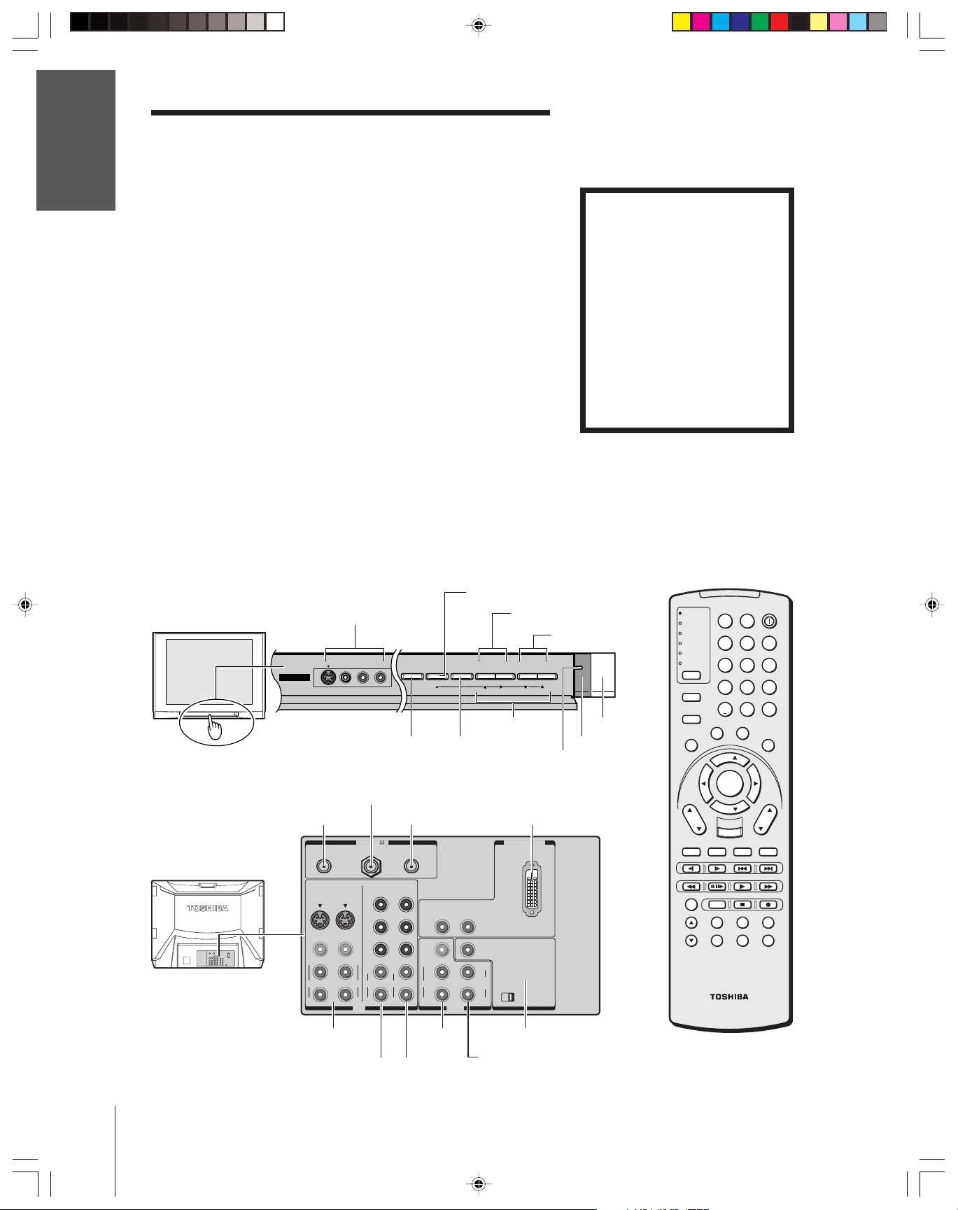
Exploring your new TV
You can operate your TV by using the buttons on the front panel or
Using the
Remote Control
the remote control. The back panel and front panel (behind the door)
provide all the terminal connections you will need to connect other
equipment to your TV. See “Connecting your TV” on page 7.
Illustrations represent 36HFX73.
Note regarding
Quick Connect Guide
The Quick Connect Guide
automatically appears on-screen
the first time the TV is turned on.
This feature provides on-screen
instructions to guide you through
initial setup of your TV.
To stop the Quick Connect
Guide, either press EXIT or turn off
the TV.
See page 24 for details.
your TV
Setting up
Features
Using the TV’s
Appendix
TV front
TV rear
Video/audio inputs
(Video 3)
Behind the door
VIDEO-3 IN
VIDEOS-VIDEO L/MONO-AUDIO-R
ANT OUT
ANT-1 IN
ANT-1 ANT-2OUT
VIDEO 1
VIDEO 2
S-VIDEO
S-VIDEO
VIDEO
VIDEO
L/
MONO
MONO
AUDIO
AUDIO
R
ANT( 75
COLOR
STREAM HD-1
Y
P
B
P
R
L/
L
AUDIO
R
R
IN
MENU
DEMO MENU TV/VIDEO V OLUME CHANNEL
Menu
x •zy
DVI/HDCP IN
L
L
VAR
AUDIO
R
ON OFF
ANT-2 IN
)
COLOR
STREAM HD-2
Y
P
B
P
R
L
AUDIO
R
TV/VIDEO
AUDIO
R
VIDEO
L/
MONO
AUDIO
R
OUT
VOLUME x •
CHANNEL zy
Power indicator
DVI/HDCP IN
AUDIO CENTER
CHANNEL IN
Remote sensorDEMO
POWER
TV
CABLE/SAT
VCR
DVD
AUDIO1
AUDIO2
MODE
PIC SIZE
ACTION
MENU
E
D
I
U
G
P
U
T
E
S
CH
DVD RTN
CH RTN
SLOW/DIR
TV/
VCR
POP CH
LIGHT SLEEP
123
456
789
+10
100/
0
F
A
V
O
O
F
N
I
S
U
B
E
L
T
T
I
T
I
T
FAV
ENTER
FAV
EXIT
DVD CLEAR
INPUT
RECALL
SKIP/SEARCH
PAUSE/STEP
PLAYREW FF
AM/FM
STOP
DISC
POP DIRECT CH
SPLIT
CH SCAN
SWAP
CT-90164
POWER
ENT
R
I
T
E
T
H
E
A
T
L
E
I
N
R
K
L
E
A
U
D
I
O
VOL
MUTE
REC
FREEZE
SOURCE
Index
VIDEO 1/2
ColorStream
HD-1
Video/
Audio OUT
ColorStream
HD-2
Audio Center Channel IN
Variable Audio OUT
6
Page 7
Connecting your TV
Note: Cables are not supplied with your TV.
●
Coaxial cable is the cable that comes in from your antenna, cable TV
service, or cable converter box. Coaxial cable uses “F” connectors.
●
Standard A/V (audio/video) cables usually come in sets of three, and
are typically color-coded according to use: yellow for video, red for
stereo right audio, and white for stereo left (or mono) audio.
On your TV’s back panel, the standard A/V inputs are color-coded in
the same manner as the cables.
●
S-Video cable is for use with video equipment with S-Video output.
●
Component video cables come in sets of three, (color-coded red,
green and blue) and are for use with video equipment with component
video outputs. ColorStream
●
DVI-D digital single-link cable is for use with video equipment with
DVI-D output (see page 13).
NOTE REGARDING PICTURE QUALITY
When connecting video equipment to your Toshiba TV:
●
For GOOD picture quality: Use a standard yellow video cable.
●
For BETTER picture quality:
input, use an S-video cable instead of a standard yellow video cable.
(You still must connect the standard red and white audio cables for full
system connection, but do not connect the standard yellow video cable at
the same time, or the picture performance will be unacceptable.)
●
For BEST picture quality: If your equipment has component video (or
DVI) inputs, use either component video cables (or a DVI cable) instead
of a standard video or S-video cable. (You still must connect the standard
red and white audio cables for full system connection, but do not connect
the standard yellow video cable or an S-Video cable at the same time.)
®
is Toshiba’s brand of component video.
If your equipment has an S-video
Coaxial (antenna) cable
Standard A/V cables (red/white/yellow)
S-video cable
Component video cables (red, green, blue)
DVI-D digital single-link cable
CAUTION:
Do not plug in any power cords until you have
finished connecting all equipment.
Introduction
your TV
Connecting
Using the
Remote Control
your TV
Setting up
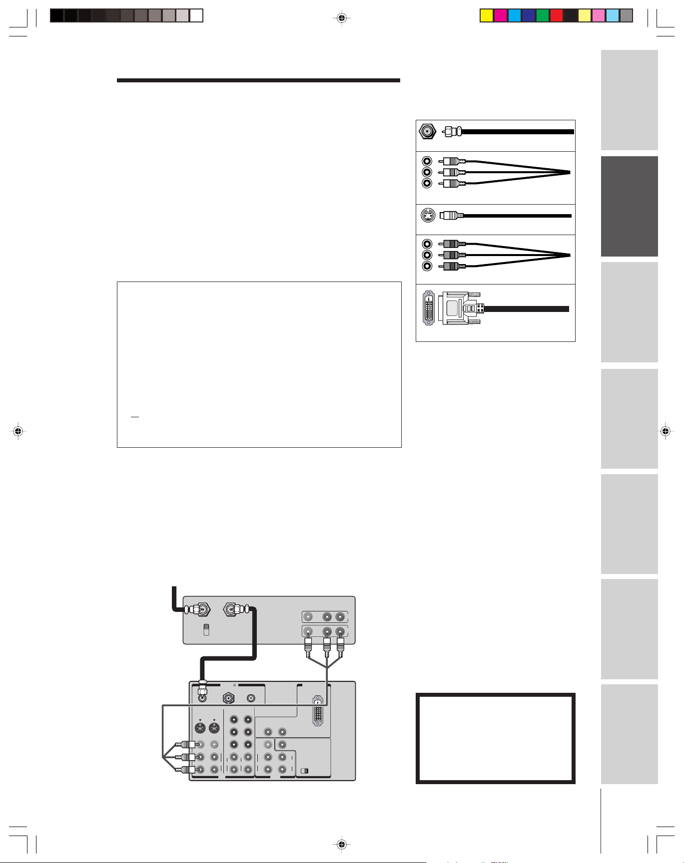
Connecting a VCR
This connection allows you to watch local channels and video
programs, play or record on the VCR while watching TV, and record
from one channel while watching another channel.
You will need:
• two coaxial cables
• one set of standard A/V cables
From Cable Box or Antenna
Stereo VCR
VIDEO AUDIO
LR
IN from ANT
CH 3
CH 4
ANT-1 ANT-2OUT
VIDEO 1
S-VIDEO
VIDEO
L/
MONO
AUDIO
R
TV
OUT to TV
VIDEO 2
S-VIDEO
VIDEO
MONO
AUDIO
ANT( 75
COLOR
STREAM HD-1
P
P
L/
L
AUDIO
R
R
IN
)
COLOR
STREAM HD-2
Y
Y
AUDIO
P
B
P
R
L
AUDIO
R
VIDEO
L/
MONO
AUDIO
R
R
OUT
B
R
DVI/HDCP IN
L
AUDIO CENTER
CHANNEL IN
L
VAR
AUDIO
ON OFF
R
IN
OUT
Note:
If you have a mono VCR, connect L/Mono to
VCR Audio OUT using only one audio cable.
If you have a VCR with S-video, use an
S-video cable (plus audio cables) instead of
the standard video cable for better picture
performance.
Do not connect a standard video cable and
an S-video cable to VIDEO 1 (or VIDEO 2) at
the same time or the picture performance will
be unacceptable.
The unauthorized recording, use,
distribution, or revision of television
programs, videotapes, DVDs, and other
materials is prohibited under the
Copyright Laws of the United States and
other countries, and may subject you to
civil and criminal liability.
Features
Using the TV’s
Appendix
Index
7
Page 8
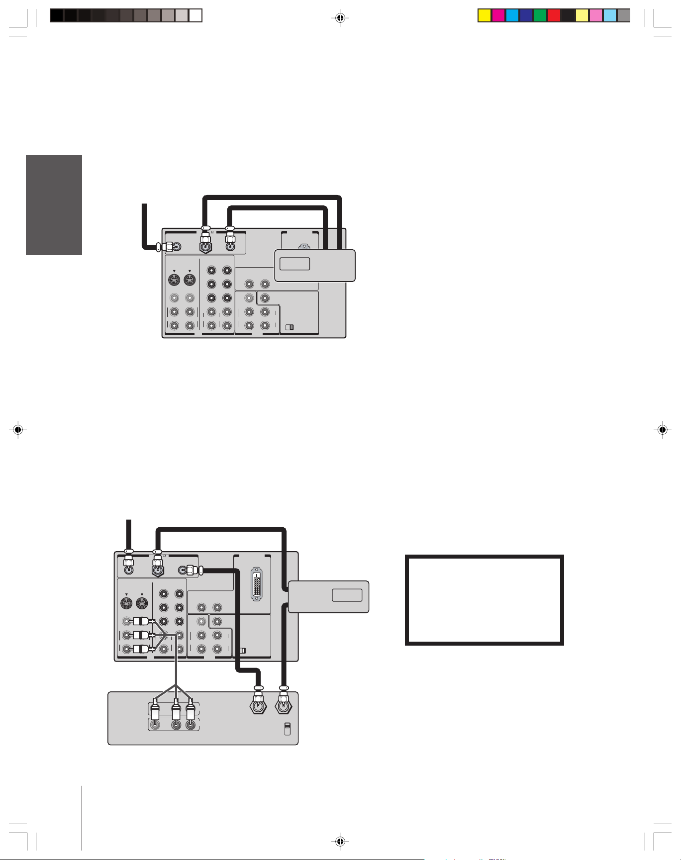
Connecting a cable box
This connection allows you to watch basic and premium cable channels
To watch basic cable and use the TV’s features, select ANT-1. To view
Introduction
premium channels, select ANT-2, tune the TV to channel 3 or 4
(whichever channel is vacant in your area), and use the cable box to
change channels.
You will need:
your TV
Connecting
Using the
Remote Control
Connecting a cable box and VCR
This connection allows you to watch and record basic and premium
cable channels, watch videotapes, and record one channel while
watching another channel. To watch basic cable and use the TV’s
features, select ANT-1.
your TV
Setting up
Features
Using the TV’s
Appendix
To view premium channels or record with the VCR, select ANT-2,
tune the TV to channel 3 or 4 (whichever channel is vacant in your
area), and use the cable box to change channels.
You will need:
From Cable
• three coaxial cables
From Cable
TV
)
ANT( 75
ANT-1 ANT-2OUT
COLOR
VIDEO
MONO
AUDIO
STREAM HD-1
Y
P
B
P
R
L/
L
AUDIO
R
R
IN
COLOR
STREAM HD-2
Y
P
B
P
R
L
AUDIO
R
VIDEO 1
S-VIDEO
VIDEO
L/
MONO
AUDIO
R
VIDEO 2
S-VIDEO
• four coaxial cables
• one set of standard A/V cables
TV
ANT-1 ANT-2OUT
VIDEO 1
S-VIDEO
VIDEO
L/
MONO
AUDIO
R
VIDEO 2
S-VIDEO
VIDEO
MONO
AUDIO
ANT( 75
COLOR
STREAM HD-1
Y
P
B
P
R
L/
L
AUDIO
R
R
IN
)
COLOR
STREAM HD-2
Y
P
B
P
R
L
AUDIO
R
VIDEO
L/
MONO
AUDIO
R
R
AUDIO
OUT
L
L
VAR
AUDIO
R
R
VIDEO
L/
MONO
AUDIO
R
DVI/HDCP IN
AUDIO CENTER
CHANNEL IN
ON OFF
AUDIO
OUT
.
Note:
When you use a cable box with your TV, the
remote control will not operate some features,
such as programming your favorite channels,
labeling channels, and locking channels.
DVI/HDCP IN
INOUT
L
L
VAR
AUDIO
ON OFF
R
AUDIO CENTER
CHANNEL IN
Cable box
Note:
If you have a mono VCR, connect L/Mono to
VCR Audio OUT using only one audio cable.
If you have a VCR with S-video, use an
S-video cable (plus audio cables) instead of a
standard video cable. Do not connect
standard video cable and an S-video cable to
VIDEO 1 (or VIDEO 2) at the same time or
the picture performance will be unacceptable.
When you use a converter box with your TV,
the remote control will not operate some
features, such as programming your favorite
channels, labeling channels, and locking
channels.
The unauthorized recording, use,
distribution, or revision of television
IN
OUT
Cable box
programs, videotapes, DVDs, and other
materials is prohibited under the
Copyright Laws of the United States and
other countries, and may subject you to
civil and criminal liability.
Index
Stereo VCR
8
VIDEO
LR
OUT
LR
AUDIO
IN
OUT to TV
IN from ANT
CH 3
CH 4
Page 9
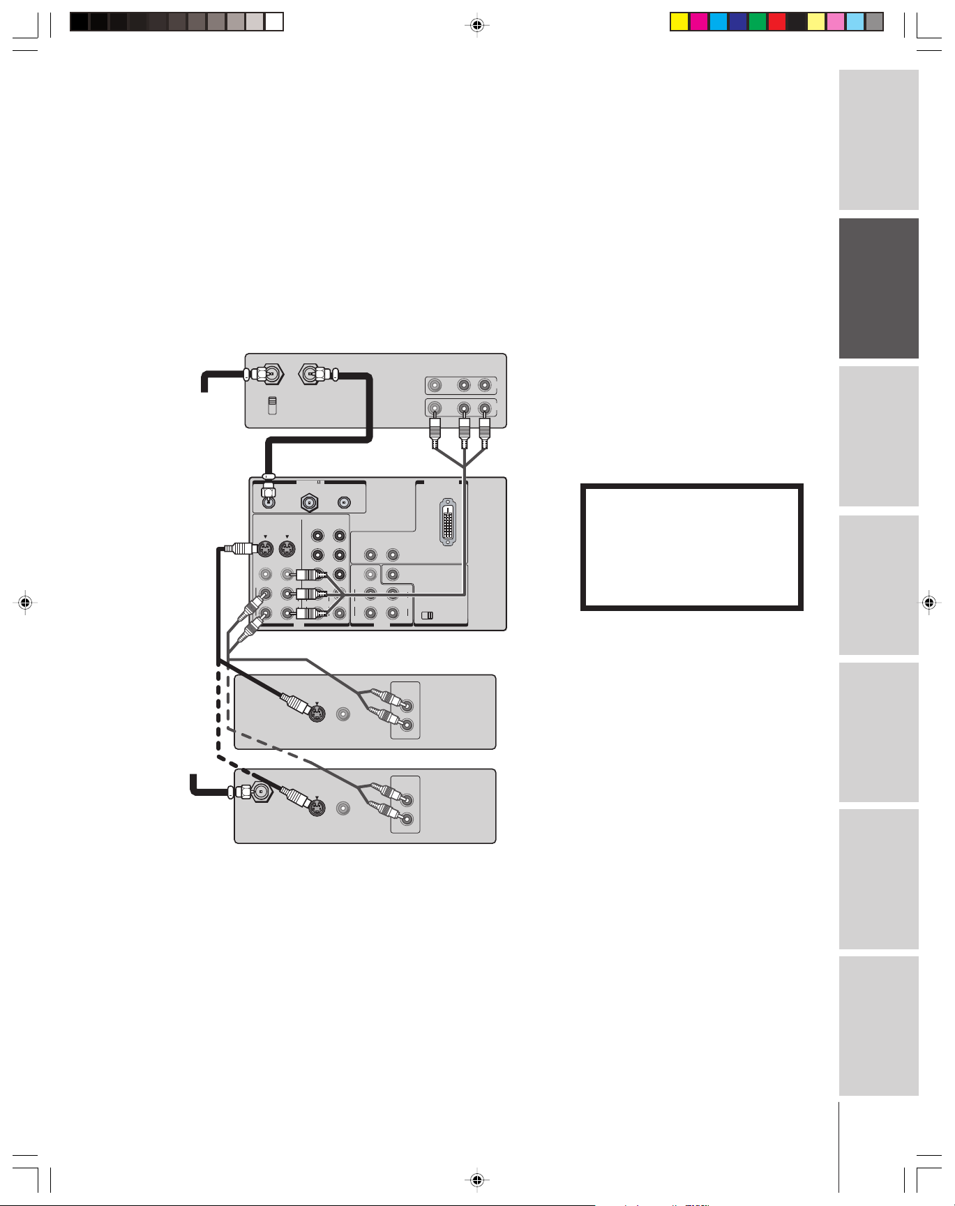
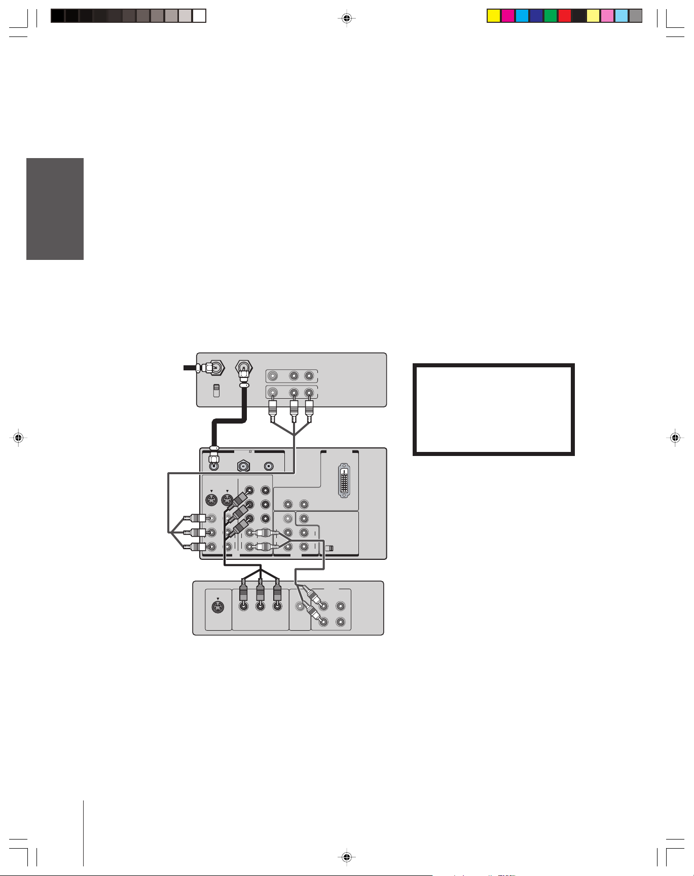
Connecting a DVD player or satellite receiver
(without component video) and a VCR
This connection allows you to watch DVD/satellite, VCR, and TV
programs, and record one TV channel while watching another
channel.
You will need:
• two coaxial cables (three if satellite receiver is used)
• one set of standard A/V cables
• one pair of audio cables
• one S-video cable (between the TV and DVD player/satellite
receiver)
Stereo VCR
VIDEO AUDIO
LR
IN
OUT
From
Antenna
IN from ANT
CH 3
CH 4
TV
ANT-1 ANT-2OUT
VIDEO 1
S-VIDEO
VIDEO
L/
MONO
AUDIO
R
VIDEO 2
S-VIDEO
VIDEO
MONO
AUDIO
OUT to TV
ANT( 75
COLOR
STREAM HD-1
Y
P
B
P
R
L/
L
AUDIO
R
R
IN
)
COLOR
STREAM HD-2
Y
P
B
P
R
L
AUDIO
R
VIDEO
L/
MONO
AUDIO
R
R
AUDIO
OUT
DVI/HDCP IN
L
AUDIO CENTER
CHANNEL IN
L
VAR
AUDIO
ON OFF
R
Note:
For the highest possible picture quality from a
DVD player/satellite receiver, without
component video (or DVI/HDCP), use an
S-video cable.
If your DVD player or satellite receiver has
component video, see page 10.
If your DVD player or satellite receiver has
DVI/HDCP, see page 13.
Do not connect an S-video cable and a
standard video cable to VIDEO 1 (or
VIDEO 2) at the same time or the picture
performance will be unacceptable.
Do not connect the DVD player/satellite
receiver and VCR to the same set of AV
inputs on the TV. (See the illustration, which
shows the DVD player/satellite receiver
connected to VIDEO 1 on the TV, and the
VCR connected to VIDEO 2 on the TV.)
The unauthorized recording, use,
distribution, or revision of television
programs, videotapes, DVDs, and other
materials is prohibited under the
Copyright Laws of the United States and
other countries, and may subject you to
civil and criminal liability.
Introduction
your TV
Connecting
Using the
Remote Control
your TV
Setting up
From
Satellite
Dish
IN from ANT
S-VIDEO
S-VIDEO
VIDEO
OUTOUT
VIDEO
OUTOUT
DVD Player
AUDIO
OUT
L
R
Satellite Receiver
AUDIO
OUT
L
R
Features
Using the TV’s
Appendix
Index
9
Page 10
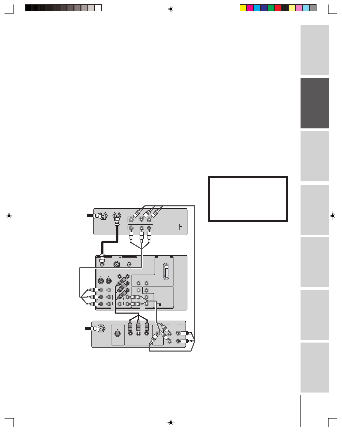
Connecting a DVD player with component
video and a VCR
This connection allows you to watch DVD, VCR, and TV programs,
Introduction
and record TV programs.
Your TV has ColorStream
your TV to a DVD player with component video inputs (such as a
Toshiba DVD player with ColorStream
quality and realism.
–To record one TV program while watching another TV program,
your TV
Connecting
–To record a TV program while watching a DVD, tune the VCR to
You will need:
Using the
Remote Control
your TV
Setting up
®
(component video) inputs. Connecting
®
) can greatly enhance picture
tune the VCR to the channel to record, and tune the TV to the
channel to watch.
the channel to record, and select ColorStream HD-1 on the TV (see
“Selecting the antenna input” on page 25).
• two coaxial cables
• one set of standard A/V cables
• one pair of audio cables
• one set of component video cables
Stereo VCR
From Antenna
IN from ANT
CH 3
CH 4
TV
OUT to TV
ANT( 75
ANT-1 ANT-2OUT
VIDEO AUDIO
)
LR
IN
OUT
DVI/HDCP IN
Note:
For the highest possible picture quality, use
component video cables (or a DVI-D singlelink cable) between the TV and DVD player.
You can connect component video cables to
either set of ColorStream jacks on the TV
(HD-1 or HD-2).
The ColorStream HD-1 and HD-2 jacks can
be used with Progressive (480p, 720p) and
Interlaced (480i,1080i) scan systems. A 1080i
signal will provide the best picture
performance.
If your DVD player does not have component
video (or DVI/HDCP), use the S-video
connections (plus the standard audio
connections instead. Do not connect both
S-Video and standard video cables to VIDEO
1 (or VIDEO 2) at the same time or the
picture performance will be unacceptable.
See page 9.
For DVI-HDCP connection, see page 13.
The unauthorized recording, use,
distribution, or revision of television
programs, videotapes, DVDs, and other
materials is prohibited under the
Copyright Laws of the United States and
other countries, and may subject you to
civil and criminal liability.
Features
Using the TV’s
Appendix
Index
COLOR
VIDEO 1
S-VIDEO
VIDEO
L/
MONO
AUDIO
R
S-VIDEO
VIDEO 2
S-VIDEO
COLOR
STREAM HD-1
STREAM HD-2
Y
Y
P
B
P
B
VIDEO
P
R
P
R
L/
MONO
L
L
AUDIO
AUDIO
AUDIO
R
R
R
IN
Y
COMPONENT VIDEO
AUDIO
R
L
VIDEO
L/
MONO
AUDIO
R
P
RPB
OUT
VIDEO
OUT
VAR
AUDIO
L
R
DVD Player with component video
ON OFF
AUDIO
L
R
AUDIO CENTER
CHANNEL IN
OUT
L
R
10
Page 11
Connecting a DTV receiver/set-top box with
component video and a VCR
This connection allows you to watch DTV (digital TV), VCR, and
TV programs, and record DTV and TV programs.
Your TV has ColorStream (component video) inputs. Connecting
your TV to a DTV receiver with component video inputs can greatly
enhance picture quality and realism.
–To record and watch a DTV program, select LINE IN on the
VCR, and select ColorStream HD-2 (or VIDEO 1 for a nonColorStream connection) on the TV (see “Selecting the antenna
input” on page 25).
–To record a TV program while watching a DTV program, tune the
VCR to the channel to record, and select ColorStream HD-2 on
the TV.
–To record and watch the same TV program, tune the VCR to the
channel to record, and select VIDEO 1 on the TV.
–To record one TV program while watching another TV program,
tune the VCR to the channel to record, and tune the TV to the
channel to watch.
You will need:
• three coaxial cables
• two sets of standard A/V cables
• one pair of audio cables
• one set of component video cables
Stereo VCR
IN from ANT
From
Antenna
OUT to TV
VIDEO AUDIO
LR
OUT
IN
CH 3
CH 4
Note:
For the highest possible picture quality, use
component video cables (or a DVI-D singlelink cable) between the TV and DTV receiver.
You can connect component video cables to
either set of ColorStream jacks on the TV
(HD-1 or HD-2).
The ColorStream HD-1 and HD-2 jacks can
be used with Progressive (480p, 720p) and
Interlaced (480i,1080i) scan systems. A 1080i
signal will provide the best picture
performance.
If your DTV receiver does not have
component video (or DVI/HDCP), use the
S-video and standard audio connections
instead. Do not connect both an S-video and
a standard video cable to VIDEO 1 (or
VIDEO 2) at the same time or the picture
performance will be unacceptable.
For DVI/HDCP connection, see page 13.
The unauthorized recording, use,
distribution, or revision of television
programs, videotapes, DVDs, and other
materials is prohibited under the
Copyright Laws of the United States and
other countries, and may subject you to
civil and criminal liability.
Introduction
your TV
Connecting
Using the
Remote Control
your TV
Setting up
From
DTV Antenna
TV
ANT-1 ANT-2OUT
VIDEO 1
S-VIDEO
VIDEO
L/
MONO
AUDIO
R
Satelite IN
VIDEO 2
S-VIDEO
VIDEO
MONO
AUDIO
ANT( 75
COLOR
STREAM HD-1
Y
P
B
P
R
L/
L
AUDIO
R
R
IN
S-VIDEO
)
COLOR
STREAM HD-2
Y
P
B
VIDEO
P
R
L/
MONO
L
AUDIO
AUDIO
R
R
Y
COMPONENT VIDEO
R
AUDIO
OUT
P
DTV Receiver with component video
DVI/HDCP IN
Features
L
AUDIO CENTER
CHANNEL IN
L
VAR
AUDIO
ON OFF
R
AUDIO
OUT
VIDEO
OUT
LRL
R
RPB
Using the TV’s
Appendix
Index
11
Page 12
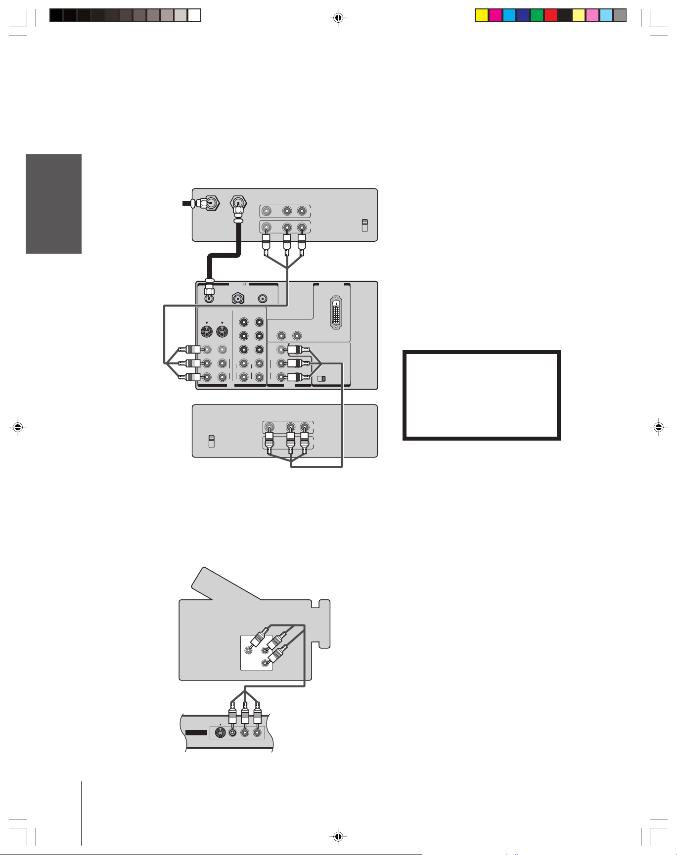
Connecting two VCRs
This connection allows you to record (dub/edit) from one VCR to
another VCR while watching a videotape. You can also record from
Introduction
your TV
Connecting
Using the
Remote Control
your TV
Setting up
one TV channel while watching another TV channel.
You will need:
• two coaxial cables
• two sets of standard A/V cables
VCR1
IN from ANT
OUT to TV
From Antenna
TV
VIDEO
L/
MONO
AUDIO
R
VCR2
CH 3
CH 4
ANT-1 ANT-2OUT
VIDEO 1
VIDEO 2
S-VIDEO
S-VIDEO
VIDEO
L/
MONO
AUDIO
ANT( 75
COLOR
STREAM HD-1
Y
P
B
P
R
L
AUDIO
R
R
IN
VIDEO AUDIO
)
COLOR
STREAM HD-2
Y
P
B
VIDEO
P
R
L/
MONO
L
AUDIO
AUDIO
R
R
VIDEO AUDIO
LR
IN
OUT
DVI/HDCP IN
AUDIO
R
L
L
VAR
AUDIO
ON OFF
R
OUT
LR
IN
OUT
AUDIO CENTER
CHANNEL IN
CH 3
CH 4
Note:
If VCR 1 has S-video, you can use an S-video
cable instead of standard video cable for
better picture performance. Do not connect
both a standard video cable and an S-video
cable to VIDEO 1 (or VIDEO 2) at the same
time, or the picture performance will be
unacceptable.
Do not connect the same VCR to the output
and input jacks on the TV at the same time.
To dub or edit, VCR 2 must select Line IN,
and the TV must select VIDEO 1 (see
“Selecting the antenna input” on page 25).
The unauthorized recording, use,
distribution, or revision of television
programs, videotapes, DVDs, and other
materials is prohibited under the
Copyright Laws of the United States and
other countries, and may subject you to
civil and criminal liability.
Features
Using the TV’s
Appendix
Index
***
Connecting a camcorder
This connection allows you to watch video materials recorded on a
camcorder.
You will need:
• one set of standard A/V cables
Camcorder
VIDEO
AUDIO
OUT
L
R
VIDEO-3 IN
VIDEOS-VIDEO L/MONO-AUDIO-R
The VIDEO OUT jack does not output the
*
POP picture.
The AUDIO OUT jacks can output the
**
sound of either the Main or POP picture
(see “Selecting the Audio OUT sound” on
page 56).
Note:
If your camcorder has S-video, you can use
an S-video cable instead of the standard
video cable for better picture performance.
Do not connect both a standard video cable
and an S-video cable at the same time, or the
picture performance will be unacceptable.
12
Video-3 (front panel)
Page 13
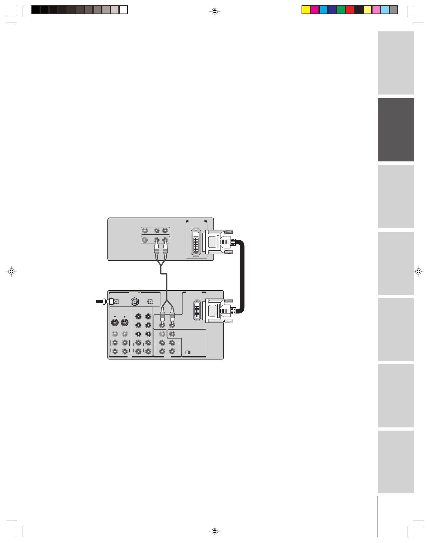
Connecting a device to the DVI/HDCP input
The DVI/HDCP1 input on your TV is designed to accept HDCP
program material in digital form from EIA/CEA-861–compliant
2
consumer electronic devices, such as a set-top box or DVD player
equipped with a DVI-D digital single-link output connection.
3
The DVI/HDCP input is designed for best performance with 1080i
high-definition video signals. The DVI/HDCP input also will accept
and display 480p, 480i, and 720p picture signals.
Note: This TV is not intended for connection to
and should not be used with a PC (personal
computer).
You will need:
• one coaxial cable
• one pair of standard audio cables
• one DVI-D digital single-link cable
Note: For proper operation, the DVI-D cable length
should not exceed 3m (9.8 ft). The recommended
length is 2m (6.6 ft).
DVI/HDCP device
(for example, set-top box or DVD player)
VIDEO AUDIO
LR
IN
OUT
DVI/ HDCP
OUT
Note:
1
DVI/HDCP = Digital Visual Interface/
High-bandwidth Digital Content Protection.
2
EIA/CEA-861 compliance covers the
transmission of uncompressed digital
video with high-bandwidth digital content
protection, which is being standardized for
reception of high-definition video signals.
3
Consult your consumer electronics dealer
for availability.
Caution:
To ensure that the DVI/HDCP device is reset
properly, it is recommended that you follow
these procedures:
• When turning on your electronic
components, turn on the TV first,
and then the DVI/HDCP device.
• When turning off your electronic
components, turn off the DVI/HDCP
device first, and then the TV.
Introduction
your TV
Connecting
Using the
Remote Control
From
antenna
or cable
TV
ANT-1 ANT-2OUT
VIDEO 1
S-VIDEO
VIDEO
L/
MONO
AUDIO
R
VIDEO 2
S-VIDEO
VIDEO
MONO
AUDIO
ANT( 75
COLOR
STREAM HD-1
Y
P
P
L/
L
AUDIO
R
R
IN
B
R
)
COLOR
STREAM HD-2
Y
P
B
P
R
L
AUDIO
R
VIDEO
L/
MONO
AUDIO
R
R
AUDIO
OUT
your TV
Setting up
DVI/HDCP IN
L
AUDIO CENTER
CHANNEL IN
VAR
AUDIO
L
ON OFF
R
Features
Using the TV’s
Appendix
13
Index
Page 14
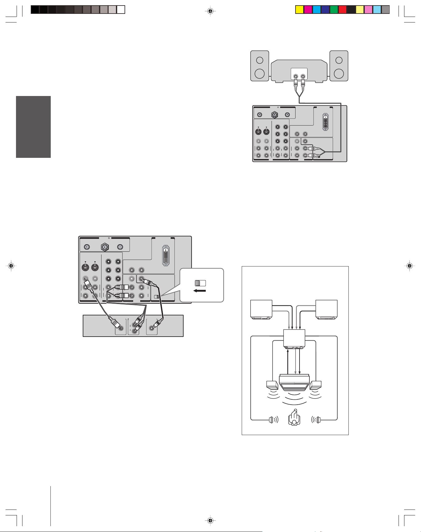
Connecting an audio system
This connection allows you to use external speakers with an external
audio amplifier to adjust the sound level.
Introduction
To control the audio, turn on the TV and the stereo amplifier, and
turn off the built-in speakers (see “Turning off the built-in speakers”
on page 56).
You will need:
Note:
To hear sound when using an external audio amplifier, the
your TV
Connecting
volume of both the TV and the amplifier must be set to a
moderate listening level.
Connecting an A/V receiver
This connection allows you to use an audio/video (A/V) receiver to
enhance your TV’s sound.
If you have a sound system with Dolby Pro Logic surround sound,
you can add to the realism of the sound by using the TV’s internal
speakers as center channel speakers.
Using the
Remote Control
You will need:
• one pair of audio cables
• one set of standard A/V cables
• one single standard audio cable for the audio center channel
)
ANT( 75
ANT-1 ANT-2OUT
DVI/HDCP IN
Amplifier
LINE IN
LR
TV
ANT-1 ANT-2OUT
VIDEO 1
S-VIDEO
VIDEO
L/
MONO
AUDIO
R
VIDEO 2
S-VIDEO
VIDEO
MONO
AUDIO
ANT( 75
COLOR
STREAM HD-1
L/
R
IN
Y
P
B
P
R
L
AUDIO
R
)
COLOR
STREAM HD-2
Y
P
B
P
R
L
AUDIO
R
VIDEO
L/
MONO
AUDIO
R
DVI/HDCP IN
AUDIO
R
L
AUDIO CENTER
CHANNEL IN
L
VAR
AUDIO
ON OFF
R
OUT
Caution:
To avoid damaging the speakers:
• Turn off the TV before connecting or
disconnecting the Audio Center Channel
cable.
• Do not connect from the A/V receiver’s
amplified center speaker OUT to the TV’s
Audio Center Channel IN.
your TV
Setting up
Features
Using the TV’s
Appendix
Index
COLOR
VIDEO
MONO
AUDIO
STREAM HD-1
P
P
L/
L
AUDIO
R
R
IN
COLOR
STREAM HD-2
Y
Y
B
P
B
R
P
R
L
AUDIO
R
VIDEO
L/
MONO
AUDIO
R
R
AUDIO
OUT
L
AUDIO CENTER
CHANNEL IN
L
VAR
AUDIO
ON OFF
R
VIDEO 1
S-VIDEO
VIDEO
L/
MONO
AUDIO
R
VIDEO 2
S-VIDEO
TV
Video
AudioINCenter
OUT
AUDIO
L
R
OUT
A/V Receiver
Note:
Refer to the instructions provided with your A/V receiver
for details about your surround sound system.
When the Audio Center Channel ON/OFF switch is in
the ON position, the TV speakers will function only as
center channel speakers.
Adjust the volume for the center channel speakers
using the center level control on the A/V receiver.
To use the TV speakers as normal speakers, set the
Audio Center Channel ON/OFF switch to the OFF
position.
If you use the built-in sound feature, see “Enjoying the
Dolby Virtual sound feature” on page 53.
ON OFF
Dolby Pro Logic* surround sound
system connection example
Audio Video
VCR
Video
A/V receiver
Audio
Video
T V
Left
speaker
Surround
speaker L
_________
* “Dolby” and “Pro Logic” are trademarks of
Dolby Laboratories.
Audio
Audio
center
channel
Surround
speaker R
LDP/DVD
Right
speaker
14
Page 15
Using the remote control
Preparing the remote control for use
Your Toshiba TV remote control has one dedicated TV mode and five
universal modes: VCR, Cable/SAT, DVD, Audio1, and Audio2. The
target devices and default devices being programmed for each mode
are as follows:
Target device/Mode mapping
Mode Device
TV Toshiba TV
CABLE/SAT Universal Cable, Satellite
VCRUniversal VCR, DVD, LD, Cassette
DVDUniversal DVD, VCR, LD, Cassette
AUDIO1 Universal Audio: Amp., Tuner, Misc.Audio, CD/MD
AUDIO2 Universal Audio: CD/MD, Amp., Tuner, Misc.Audio
Default device codes
Mode Default device
TV Toshiba TV
CABLE/SAT Toshiba Satellite receiver
VCRToshiba VCR
DVDToshiba DVD
AUDIO1 Pioneer Audio receiver
AUDIO2 Pioneer LD
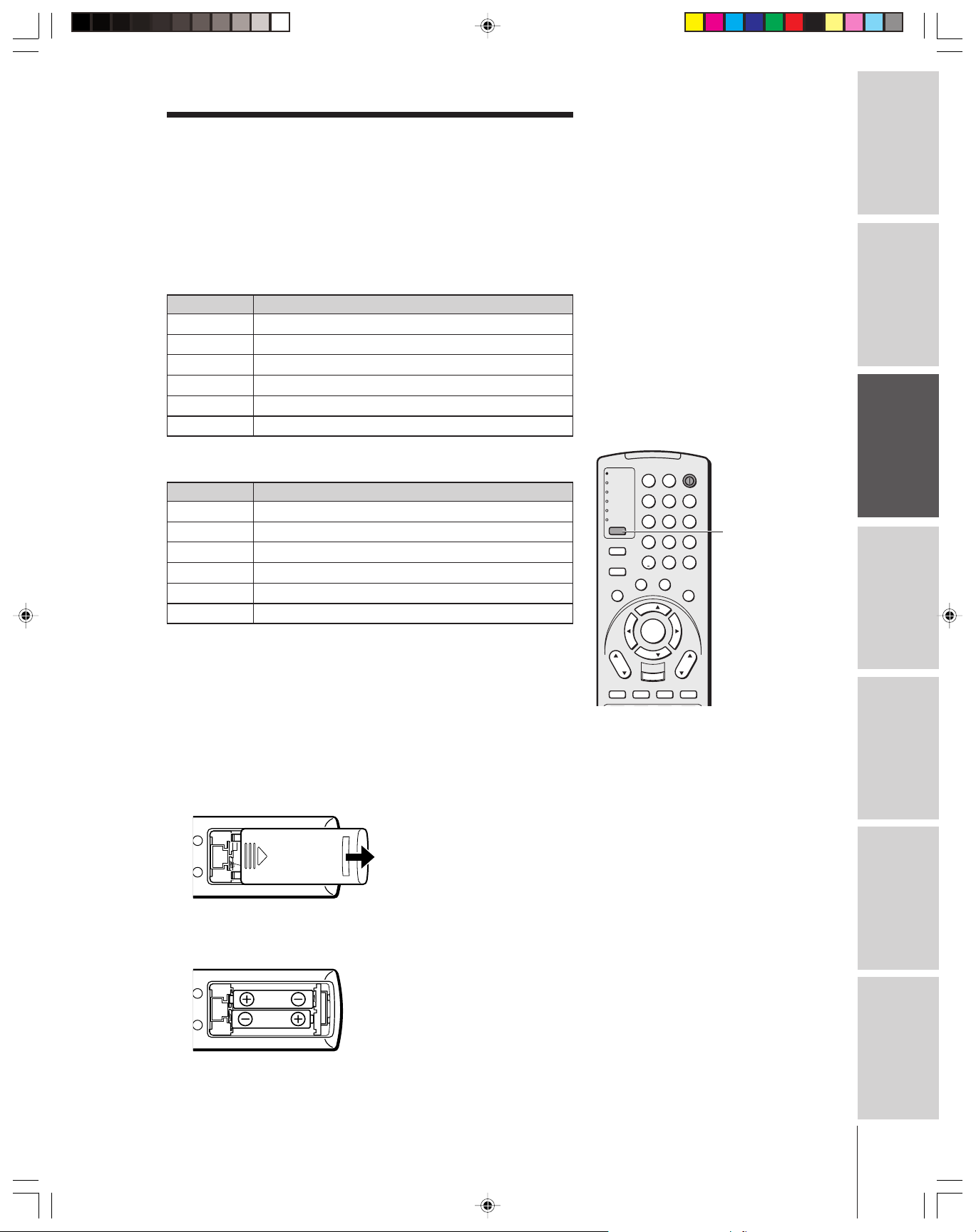
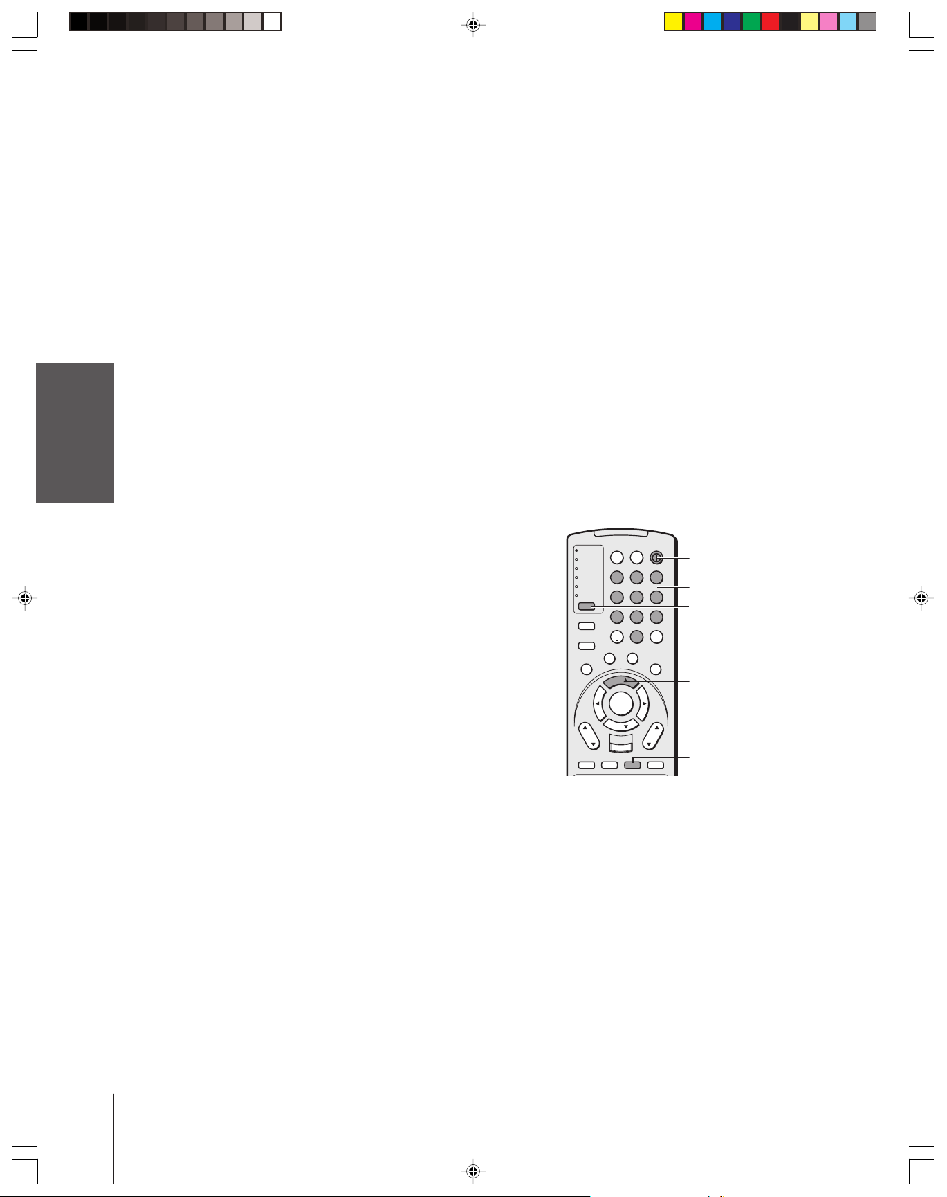
Repeatedly press MODE to cycle among the modes. If you own
different brands of audio/video devices,you must first program your
remote control (see “Programming the remote control for use with
your audio/video devices” on page 18).
Note:
Your TV’s remote control may not operate
certain features on your VCR, cable TV
converter, or other electronic device.
Refer to the owner’s manuals for your other
devices to determine their available features.
If your TV’s remote control does not operate a
specific feature on a device,use the remote
control that came with the device.
TV
CABLE/SAT
VCR
DVD
AUDIO1
AUDIO2
MODE
PIC SIZE
ACTION
MENU
E
D
I
U
G
P
U
T
E
S
CH
DVD RTN
CH RTN
SLOW/DIR
N
I
INPUT
F
T
POWER
LIGHT SLEEP
123
456
789
+10
100/
ENT
0
F
A
V
O
O
R
I
T
E
S
U
B
E
L
T
T
I
T
I
L
E
A
U
D
I
FAV
ENTER
FAV
VOL
EXIT
DVD CLEAR
RECALL
MUTE
SKIP/SEARCH
MODE
T
H
E
A
T
L
E
I
N
R
K
O
Introduction
your TV
Connecting
Using the
Remote Control
your TV
Setting up
Installing the remote control batteries
To install the batteries:
1. Slide the battery cover off the back of the remote control.
2. Install two “AA” size alkaline batteries. Match the + and – signs
on the batteries to the signs on the battery compartment.
3. Slide the battery cover on to the remote control until the lock
snaps.
Caution:
• Dispose of batteries in a designated
disposal area.Do not throw batteries into a
fire.
• Do not mix battery types or combine used
batteries with new ones.
• If the remote control does not operate
correctly, or if the operating range becomes
reduced, replace both batteries with new
ones.
• If the batteries are dead or if you will not
use the remote control for a long time,
remove the batteries to prevent battery acid
from leaking into the battery compartment.
Features
Using the TV’s
Appendix
Index
15
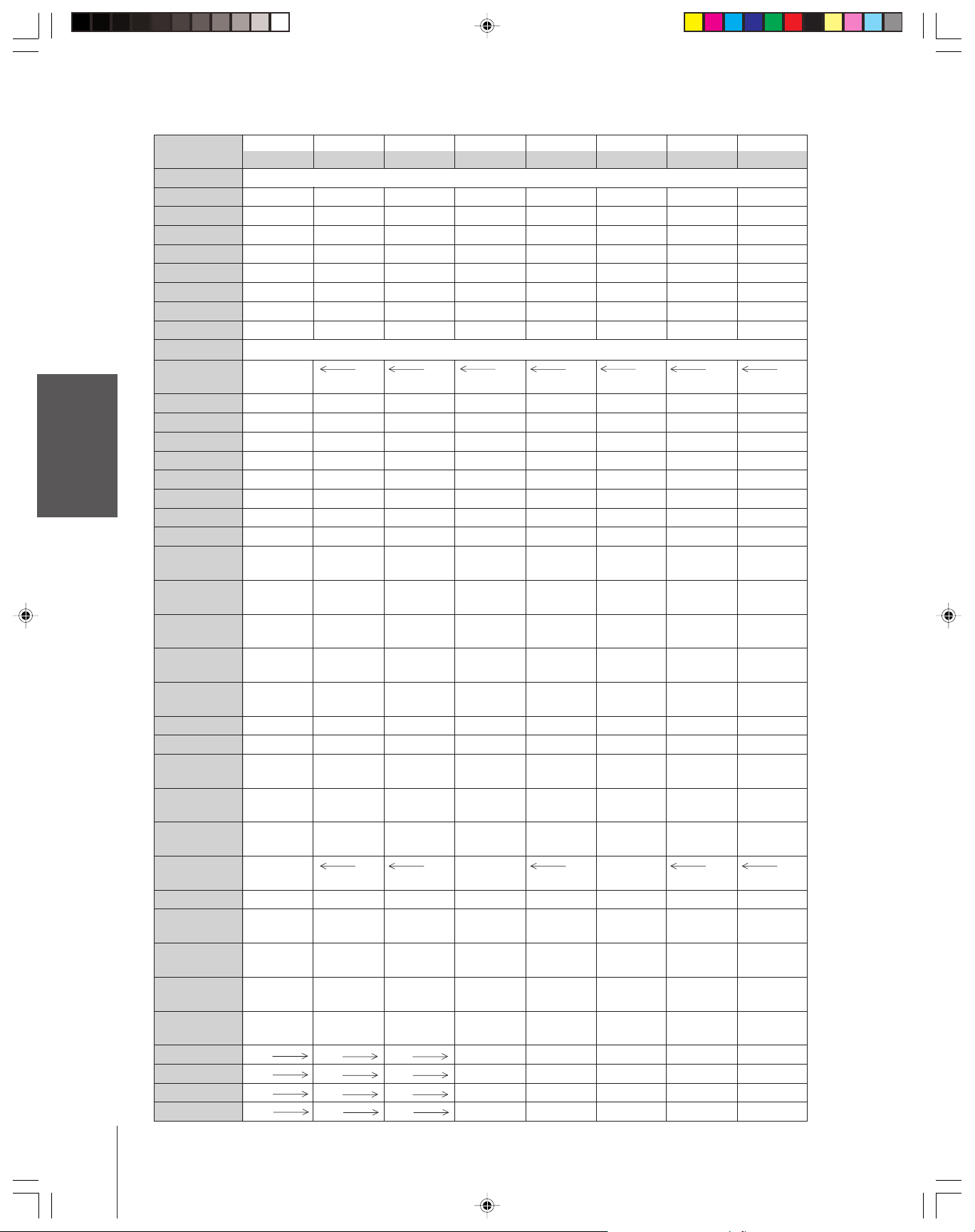
Page 16
Remote Control functional key chart
Introduction
your TV
Connecting
Using the
Remote Control
your TV
Setting up
Features
Using the TV’s
Appendix
Index
LIGHT Lights the remote key, and toggles between enabled and disabled Illumination mode.
SLEEP Sleep timer --- --- --- --- --- --- --POWER Power Power Power Power Power Power Power Power
1Digit 1 Digit 1 Digit 1 Digit 1 Digit 1 AV input 1 Digit 1 Digit 1
2Digit 2 Digit 2 Digit 2 Digit 2 Digit 2 AV input 2 Digit 2 Digit 2
3Digit 3 Digit 3 Digit 3 Digit 3 Digit 3 AV input 3 Digit 3 Digit 3
4Digit 4 Digit 4 Digit 4 Digit 4 Digit 4 AV input 4 Digit 4 Digit 4
5Digit 5 Digit 5 Digit 5 Digit 5 Digit 5 CD Digit 5 Digit 5
6Digit 6 Digit 6 Digit 6 Digit 6 Digit 6 Tuner Digit 6 Digit 6
MODE Remote control device mode selection
PIC SIZE Selects the TV TV TV TV TV TV TV
7Digit 7 Digit 7 Digit 7 Digit 7 Digit 7 Phono Digit 7 Digit 7
8Digit 8 Digit 8 Digit 8 Digit 8 Digit 8 Cassette Digit 8 Digit 8
9Digit 9 Digit 9 Digit 9 Digit 9 Digit 9 Aux Digit 9 Digit 9
ACTION --- --100/– 100 --- 100/- --- +10 --- --- --0Digit 0 Digit 0 Digit 0 Digit 0 Digit 0 Digit 0 Digit 0, 10 Digit 0
ENT (CH Enter)
GUIDE/SETUP
INFO/TITLE --- --- INFO --- TITLE= --- --- ---
FAVORITE/ Favorites --SUBTITLE
THEATERLINK/
AUDIO
MENU/ Menu --- Action, --- Menu --- --- --ACTION Menu
yz (FAV yz)Menu select --- Menu select --- Menu select --- --- ---
x • Menu select --- Menu select --- Menu select --- --- ---
ENTER Enter --- Select --- Enter --- --- --VOL
EXIT/ Exit --- Exit --- DVD clear --- --- --DVD CLEAR
CH
INPUT TV/Video TV TV VCR input TV --- TV TV
MUTE
RECALL On-screen On-screen On-screen On-screen On-screen --- --- ---
CH RTN/ Previous Previous Previous --- DVD --- --- --DVD RTN channel channel channel return
SLOW/
DIR x--- --- --- --- Slow REV --- --- ---
SKIP/
SEARCH x--- --- --- --- Skip REV
REW VCR VCR VCR Rewind Rewind
PAUSE/STEP VCR VCR VCR Pause Pause
PLAY VCR VCR VCR Play Play
FF VCR VCR VCR Fast FWD Fast FWD --- Fast FWD Fast FWD
16
Key Label
yz Volume Volume Volume Volume Volume Volume Volume Volume
yz Channel Channel Channel Channel --- Channel --- ---
Toshiba TV Cable Satellite VCR DVD/LD Receiver CD/MD Cassete
(TV) (CBL/SAT) (CBL/SAT) (AUDIO) (AUDIO) (VCR)
image shape.
Action, Menu
--- CH Enter --- --- --- --- --- ---
--- --- Guide --- DVD setup --- --- ---
Favorites
--- --- --- --- Audio --- --- ---
FAV yz
up/down* up/down* up/down* up/down* up/down* up/down* up/down* up/down*
up/down up/down up/down up/down up/down
select
Sound mute* Sound mute* Sound mute* Sound mute* Sound mute* Sound mute* Sound mute* Sound mute*
display display display display display
•
--- --- --- Slow FWD Slow FWD --- --- ---
•
--- --- --- --- Skip FWD
--- Menu --- --- ---
Top menu
--- Subtitle --- --- ---
---
---
---
---
---
Skip FWD
Skip REV
Rewind Rewind
Pause Pause
Play Play
---
---
Page 17
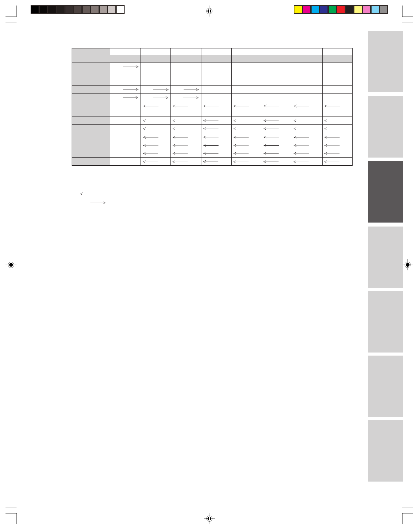
Key Label
TV/VCR VCR
AM/FM --- --- --- --- Disc shift AM/FM Disc shift Deck side
DISC A/B switch
STOP VCR VCR VCR Stop Stop --- Stop Stop
REC
**
POP CH
SPLIT POP Split TV TV TV TV TV TV TV
POP DIRECT CH POP Direct ch
FREEZE POP Freeze TV TV TV TV TV TV TV
SWAP POP Swap TV TV TV TV TV TV TV
CH SCAN POP
SOURCE POP Source TV TV TV TV TV TV TV
Notes:
•“---” will send nothing.
•“ TV” will jump to TV.
•“VCR ” will jump to last active VCR or DVD. Active VCR/DVD is defined as the mode that remains for a minimum of 5
seconds, or if a key is pressed in that mode.
The VOLUME and MUTE will jump to “TV” by default. When the volume is unlocked, all the devices will have their own volume.
*
The AUDIO1/2 (Receiver, CD) modes will have their own volume even if Volume Lock is on TV, CABLE/SAT, VCR, or DVD. See
“Using the Volume Lock feature” on page 19.
Press the REC button two times within 5 seconds to record each audio/video source.
**
Toshiba TV Cable Satellite VCR DVD/LD Receiver CD/MD Cassete
(TV) (CBL/SAT) (CBL/SAT) (AUDIO) (AUDIO) (VCR)
---
VCRVCR VCR Record** --- --- --- Record**
yz
POP channel TV TV TV TV TV TV TV
up/down
TV TV TV TV TV TV TV
Ch scan
TV TV TV TV TV TV TV
TV/SAT TV/VCR --- --- --- Reverse
Introduction
your TV
Connecting
Using the
Remote Control
your TV
Setting up
Features
Using the TV’s
Appendix
17
Index
Page 18
Programming the remote control for use with
your audio/video devices
Introduction
Device code setup
your TV
Connecting
Using the
Remote Control
your TV
Setting up
Searching and sampling the code of a device (8500)
If you do not know the device code for a particular target unit, you
can cycle the remote control through the available codes for that
device mode and sample the functions to find the code that properly
operates the target device. The keys available to be sampled, provided
they are applicable to that mode, are POWER, 1, VOL y, CH y, and
PLAY. Invalid keys will be ignored while in program mode.
To cycle through each available device code and sample its functions:
Features
Using the TV’s
Appendix
1. Refer to the Device code table on pages 20–21 to find the code
for the brand of your device.
If more than one number is listed, try each one separately until
you find the one that works.
2. Press MODE until the Mode indicator of the device (CABLE/
SAT, VCR, DVD, AUDIO1, AUDIO2) lights up.
3. While holding down the RECALL button, press the Channel
Number buttons to enter the four-digit code of your brand of
device. If a valid code is entered, the mode indicator will blink
twice. If an invalid code is entered, the mode indicator will blink
one long blink.
4. Point the remote control at the device and press POWER to test
the code.
If the device turns on, you have entered the correct code.
If the device does not respond to the remote control, you may
have entered the wrong code. Repeat steps 3 and 4 using another
code.
Note: In addition to POWER, confirm that all necessary keys on the TV
remote control operate your device. If some keys are not operational, repeat
the device code setup using another code (if other codes are listed for your
device). If, after trying all listed codes, the necessary keys do not operate
your device, use the device’s original remote control.
5. Press MODE to select the TV mode to control the TV.
1. Press MODE to select the mode you want to set up.
2. While holding down the RECALL button, press 8 –5 –0 –0.
The remote control will enter program mode.
3. Point the remote control at the target device and press POWER
(or other function buttons that are available to be sampled).
4. If the device responds to the remote control:
Press RECALL to store the device code.
The mode indicator will blink twice and the remote control
will exit the program mode.
If the device does not respond to the remote control:
Press y, and then press POWER.
Repeat this step until the device responds to the remote
control, and then press RECALL.
Note:
• Every time you replace the batteries, you
must reprogram the remote control.
• Some newer VCRs are capable of working
on either of two remote codes.These VCRs
have a switch labeled “VCR1/VCR2.” If
your VCR has this kind of switch and does
not respond to any of the codes for your
VCR brand, set the switch to the other
position (VCR1 or VCR2) and reprogram
the remote control
• Although the remote control for your new
TV includes codes for many devices, it may
not include codes for some or all of the
features on certain devices you want to
control. If you are unable to program the
TV’s remote control to operate your device
or some of the features on that device, use
the device’s remote control or the controls
on the device.
TV
CABLE/SAT
VCR
DVD
AUDIO1
AUDIO2
MODE
PIC SIZE
ACTION
MENU
E
D
I
U
G
P
U
T
E
S
CH
DVD RTN
CH RTN
SLOW/DIR
I
F
N
T
INPUT
POWER
LIGHT SLEEP
123
456
789
+10
100/
0
F
A
V
O
O
R
I
T
E
S
U
B
E
L
T
T
I
T
I
L
E
A
U
D
FAV
ENTER
FAV
VOL
EXIT
DVD CLEAR
RECALL
SKIP/SEARCH
ENT
T
L
I
O
MUTE
POWER
Numbers
MODE
H
E
A
T
E
I
N
R
K
y
RECALL
Index
Note: When a search cycle is completed, the mode indicator will blink
three times. The remote control will begin to cycle through the
available codes again. If no key is pressed within 10 seconds while
programming, the remote control will exit the program mode and
return to the previous code.
18
Page 19
Using the volume lock feature (8000)
For the TV, CABLE/SAT, VCR, and DVD modes, the volume
controls (VOL yz and MUTE) can be programmed (locked) to the
selected device mode. This feature does not apply to the AUDIO1/2
modes.
For example, to lock the volume controls to always jump to the
CABLE/SAT mode:
1. Repeatedly press MODE to select the CABLE/SAT mode.
2. While holding down the RECALL button, press 8 –0 –0 –0.
3. Press VOL y.
The Mode indicator will blink two times (locked).
The following table describes in more detail the Volume Lock
implementation.
Volume
Locked to
TV (default)
CBL/SAT CBL/SAT CBL/SAT CBL/SAT CBL/SAT AUD1 AUD2
VCR VCR VCRVCRVCRAUD1 AUD2
DVD DVD DVD DVD DVD AUD1 AUD2
AUD1 AUD1 AUD1 AUD1 AUD1 AUD1 AUD1
AUD2 AUD2 AUD2 AUD2 AUD2 AUD2 AUD2
TV CBL/SAT VCR DVD AUD1 AUD2
TV TV TV TV AUD1 AUD2
TV
CABLE/SAT
VCR
DVD
AUDIO1
AUDIO2
MODE
PIC SIZE
ACTION
MENU
E
D
I
U
G
P
U
T
E
S
CH
DVD RTN
CH RTN
SLOW/DIR
LIGHT SLEEP
123
456
789
+10
100/
0
F
A
V
O
O
R
F
I
T
N
I
S
U
B
E
L
T
T
I
T
I
L
T
E
FAV
ENTER
FAV
EXIT
DVD CLEAR
INPUT
RECALL
SKIP/SEARCH
POWER
Introduction
Number
MODE
ENT
E
T
H
E
A
T
L
E
I
N
R
K
A
U
D
I
O
your TV
Connecting
VOL
MUTE
VOL y z
RECALL
Using the
Remote Control
To reset the volume controls to the original device code:
1. While holding down the RECALL button, press 8 –0 –0 –0.
2. Press VOL z.
The Mode indicator will blink four times (unlocked).
Operational feature reset (8900)
This feature clears all setup features not related to “Device code set
up” and resets the Volume Lock to “TV.”
To reset the features:
While holding down the RECALL button, press 8 –9 –0 –0.
The Mode indicator will blink two times, and then pause and
blink two more times.
your TV
Setting up
Features
Using the TV’s
Appendix
19
Index
Page 20

Device code table
Introduction
your TV
Connecting
Using the
Remote Control
your TV
Setting up
Features
Using the TV’s
Appendix
Index
VCR setup codes
Brand Code
ADMIRAL 0135
AIWA 0127, 0132, 0181
AKAI 0129, 0114, 0115,
0116
AUDIO DYNAMIC 0139, 0111
BELL&HOWELL 0105, 0113
BROKSONIC 0120, 0126, 0180
CANON 0123, 0125
CCE 0143
CITIZEN 0106
CRAIG 0105, 0129, 0106
CURTIS MATHES 0145, 0124, 0127
DAEWOO 0143, 0101, 0124,
0175
DBX 0139, 0110, 0111
DIMENSIA 0145
EMERSON 0143, 0126, 0119,
0103, 0125, 0142,
0120, 0118
FISHER 0105, 0108, 0109,
0107, 0113, 0165
FUNAI 0127, 0126, 0120,
0134
GE 0133, 0145, 0124
GO VIDEO 0137, 0151, 0163,
0149, 0150, 0182
GOLDSTAR 0106
GRADIENTE 0170, 0171, 0168,
0134, 0156
HITACHI 0123, 0145, 0100,
0127, 0168
INSTANT REPLAY 0124, 0123
JENSEN 0139
JVC 0139, 0110, 0111,
0134, 0157, 0158,
0184, 0185
KENWOOD 0139, 0110, 0106,
0111
LG 0159
LXI 0127, 0106, 0100,
0107, 0108, 0105,
0109
MAGNAVOX 0131, 0123, 0124,
0173
MARANTZ 0139, 0110, 0111
MARTA 0106
MEMOREX 0124, 0109
MGA 0138, 0140, 0147,
0148, 0141, 0142
MINOLTA 0100, 0145
MITSUBISHI 0138, 0140, 0147,
0148, 0141, 0142,
0161, 0164
MULTITECH 0147, 0127, 0104
NEC 0139, 0110, 0111,
0134
OLYMPIC 0124, 0123
OPTIMUS 0128, 0121, 0135,
0106
ORION 0126, 0120, 0132
PANASONIC 0123, 0124, 0121,
0122
PENNEY 0124, 0100, 0145,
0105, 0139, 0110,
0111
PENTAX 0100, 0111, 0145
PHILCO 0131, 0124, 0127,
0123, 0126, 0120,
0143
PHILIPS 0131, 0123, 0124,
0173
PIONEER 0123
PROSCAN 0145, 0100, 0123,
0124, 0131, 0146,
0101, 0102, 0133,
0174
QUASAR 0121, 0122, 0123,
0124
RADIO SHACK 0133, 0124, 0105,
0136, 0109, 0140,
0127
RCA 0133, 0145, 0100,
0123, 0124, 0131,
0146, 0101, 0102,
0170, 0172, 0174,
0176, 0183
REALISTIC 0124, 0105, 0136,
0109, 0140, 0127
SAMSUNG 0137, 0102, 0104,
0133
SAMTRON 0163
SANSUI 0139, 0126, 0120,
0152
SANYO 0105, 0109, 0113
SCOTT 0101, 0102, 0104,
0109, 0138, 0140,
0147, 0148, 0126,
0120
SEARS 0105, 0106, 0107,
0108, 0100
SHARP 0135, 0136, 0167,
0162
SHINTOM 0117
SIGNATURE 2000 0127, 0135
SINGER 0117
SONY 0128, 0129, 0130,
0153, 0154, 0155
SV2000 0127
SYLVANIA 0131, 0123, 0124,
0127, 0178
SYMPHONIC 0127, 0168, 0177
TASHIRO 0106
TATUNG 0139, 0110, 0111
TEAC 0139, 0110, 0127,
0111
TECHNICS 0121, 0122, 0123,
0124
TEKNICA 0124, 0127, 0112
THOMSON 0179, 0183
TOSHIBA 0101, 0146, 0166,
0160
VECTOR RESEARCH 0111
WARDS 0135, 0136, 0109,
0144, 0106
YAMAHA 0105, 0139, 0110,
0111
ZENITH 0144, 0106, 0169,
0180
Cable box setup codes
Brand Code
ABC 1124
ARCHER 1132, 1125
CABLEVIEW 1105, 1132
CITIZEN 1122, 1105
CURTIS 1112, 1113
DIAMOND 1124, 1132, 1125
EAGLE 1129
EASTERN 1134
GCBRAND 1132, 1105
GEMINI 1122, 1143
G.I./JERROLD 1119, 1124, 1125,
1126, 1127, 1120,
1121, 1122, 1111,
1123, 1152
HAMLIN 1140, 1141, 1142,
1145, 1118, 1112
HITACHI 1103, 1124
MACOM 1103, 1104, 1105,
1108
MAGNAVOX 1133
MEMOREX 1130
MOVIETIME 1132, 1105
OAK 1139, 1137, 1102
PANASONIC 1109, 1110, 1114,
1151, 1153
PHILIPS 1128, 1129, 1130,
1106, 1107, 1150,
1131
PIONEER 1101, 1116
PULSAR 1105, 1132
PUSER 1132
RCA 1115
REALISTIC 1132
REGAL 1112, 1118, 1140,
1141, 1142, 1145,
1149
REGENCY 1134
REMBRANT 1137, 1132, 1105,
1138
SAMSUNG 1105
S.A. 1111, 1112, 1113
SLMARK 1105, 1101
SPRUCER 1105, 1110
STARGATE 1132, 1105
TELECAPTION 1148
TELEVIEW 1101, 1105
TEXSCAN 1144
TOCOM 1135, 1136, 1147
TOSHIBA 1104, 1146
UNIKA 1132, 1125
UNIVERSAL 1122, 1132
VIDEOWAY 1106
VIEWSTAR 1129, 1130
ZENITH 1117, 1100
ZENITH/DRAKE
SATELLITE 1100
20
Page 21

Device code table
CD Player setup codes
Brand Code
ADMIRAL 6126
AIWA 6133, 6135
CARVER 6129
DENON 6142, 6151
EMERSON 6139
FISHER 6105, 6106
GARRARD 6117
HARMAN KARDON 6120, 6121,
6123, 6119
HITACHI 6107
JENSEN 6134
JVC 6140, 6141, 6145,
6148, 6151
KENWOOD 6100, 6101, 6111,
6145
LXI 6136
MAGNAVOX 6129, 6132
MARANTZ 6129
MCINTOSH 6121
NAKAMICHI 6110
ONKYO 6114, 6115
OPTIMUS 6108, 6118, 6120,
6122
PANASONIC 6124, 6125, 6127,
6150
PHILIPS 6129, 6130, 6149
PIONEER 6108
QUASAR 6125, 6127, 6124
RCA 6147, 6137, 6138,
6131, 6152
SANSUI 6110, 6146, 6113
SANYO 6105
SCOTT 6110, 6146
SHARP 6142, 6143
SHERWOOD 6120
SONY 6128
SOUNDE-SIGH 6144
TEAC 6112, 6116, 6118
TECHNICS 6127, 6124, 6125
VICTOR 6140, 6141, 6145
YAMAHA 6102, 6103, 6104
Receiver setup codes
Brand Code
ADMIRAL 4120
AIWA 4125, 4126, 4146
DENON 4134, 4135, 4136,
4143
FISHER 4104
GARRARD 4113
HARMAN KARDON 4115, 4123,
4145
JENSEN 4129
JVC 4132, 4133, 4140,
4144
KENWOOD 4100, 4108, 4141,
4142, 4147
MAGNAVOX 4127, 4128
MARANTZ 4124
MCINTOSH 4116
MITSUBISHI 4148
NAKAMICHI 4106, 4117
ONKYO 4109, 4114
OPTIMUS 4103, 4127, 4131,
4130
PANASONIC 4119, 4118, 4121
PHILIPS 4123
PIONEER 4105, 4107, 4150
QUASAR 4119, 4118, 4121
RCA 4103, 4105, 4127,
4131, 4130, 4149
SANSUI 4103, 4111, 4139
SHARP 4134, 4137
SONY 4122
SOUNDE-SIGH 4138
TEAC 4112, 4113, 4111,
4110
TECHNICS 4121, 4118, 4119
VICTOR 4132, 4133
YAMAHA 4101, 4102
Cassette Player setup codes
Brand Code
AIWA 7123, 7124, 7125
DENON 7131
FISHER 7103
JENSEN 7114
JVC 7129, 7130, 7132,
7133
KENWOOD 7100, 7107
MARANTZ 7102
NAKAMICHI 7105
ONKYO 7108, 7109, 7113
PANASONIC 7116, 7118
PHILIPS 7122, 7121
PIONEER 7104, 7106
RCA 7126, 7127, 7128,
7134, 7135
SANSUI 7105, 7110, 7112
SHARP 7131
SONY 7119, 7120
TEAC 7110, 7111, 7115
TECHNICS 7116, 7118, 7117
YAMAHA 7101, 7102
Laser Disc setup codes
Brand Code
DENON 5114
HITACHI 5100
KENWOOD 5102, 5103
MAGNAVOX 5101
MARANTZ 5114
MITSUBISHI 5114, 5118, 5119
NEC 5114
PANASONIC 5104, 5105, 5106,
5115
PHILIPS 5111
PIONEER 5114
PROSCAN 5114
QUASAR 5104, 5105, 5106,
5115
RCA 5114
SAMSUNG 5112
SANYO 5114, 5117
SHARP 5113, 5116
SONY 5107, 5108, 5109,
5110
TEAC 5114
TOSHIBA 5114
YAMAHA 5101
DVD setup codes
Brand Code
AIWA 3123
APEX 3120
DENON 3100, 3117
FERGUSON 3101
HITACHI 3111
JVC 3109
KENWOOD 3115, 3129
KONKA 3119
MITSUBISHI 3105
NORDMENDE 3101
ONKYO 3121
ORITRON 3124
PANASONIC 3100
PHILIPS 3103, 3116
PIONEER 3102
RAITE 3113
RCA 3101, 3106
SABA 3101
SAMPO 3114
SAMSUNG 3110
SHARP 3108
SILVANIA 3132, 3118
SMC 3125
SONY 3104, 3126, 3127,
3128
TECHNICS 3100
THOMSON 3101
TOSHIBA 3103
WAVE 3122
YAMAHA 3100, 3130
ZENITH 3107, 3112
VIALTA 3131
FUNAI 3132, 3118
Satellite Receiver setup codes
Brand Code
DISH NETWORK
(Echostar) 2105, 2115, 2116,
2117
ECHOSTAR 2105
EXPRESS VU 2105, 2115
G.E. 2106
G.I. (GENERAL
INSTRUMENT) 2108
GRADIENTE 2114
HITACHI 2103, 2111, 2112
HNS (Hughes) 2103
MAGNAVOX 2101, 2102
PANASONIC 2104
PHILIPS 2101, 2102, 2118
PRIMESTAR 2108
PROSCAN 2106, 2109, 2110,
2113
RCA 2106, 2109, 2110,
2113
SONY 2107
STAR CHOICE 2103, 2108
TOSHIBA 2100, 2103, 2119,
2120, 2121
UNIDEN 2101, 2102
Introduction
your TV
Connecting
Using the
Remote Control
your TV
Setting up
Features
Using the TV’s
Appendix
Index
21
Page 22

Learning about the remote control
The buttons used for operating the TV only are described here. For a
complete list of the remote control’s functions, see the “Remote
Introduction
your TV
Connecting
Using the
Remote Control
Control functional key chart” on pages 16 –17.
POWER turns the TV on and off
SLEEP sets the TV to turn off at a specific time (page 50)
LIGHT The first press of the LIGHT button lights the keypad and turns
Channel Numbers (0-9, 100) allow direct access to channels (page 27)
MODE cycles through the six device modes: TV, CABLE/SAT, VCR,
PIC SIZE cycles through the three pictures sizes: Normal, Compression,
FAVORITE allows access to the favorite channel search function (page 37)
MENU allows access to on-screen programming menus (page 23)
on the Illumination mode. With the Illumination mode on,
pressing any other key lights the keypad for 5 seconds (10 seconds
if you’re in programming mode).
Subsequent presses of the LIGHT button toggle between turning
the Illumination mode on and off.
DVD, AUDIO1, and AUDIO2. The mode indicator light will
remain lit for a few seconds (page 18).
and Zoom (page 31)
your TV
Setting up
Features
Using the TV’s
Appendix
ENTER sets programming menu information (page 23)
yz x • select or adjust programming menus (page 23)
FAV yzcycles through favorite channels (page 29)
CH yz cycles through programmed channels (page 27)
VOL yz adjusts the volume level
EXIT exits the programming menus (page 23)
INPUT selects the video input source (page 48)
MUTE mutes the sound (page 52)
RECALL displays TV status information on-screen (page 57)
CH RTN returns to the last viewed channels (page 28)
POP CH yz selects the POP (picture-out-picture) channel (page 34)
SPLIT turns the POP feature on and off (page 34)
CH SCAN
FREEZE freezes the POP picture (page 35)
SWAP switches the main and POP pictures (page 35)
allows access to the programmed channel search function (page 36)
CT-90164
Note:
The error message “Not Available” will appear
if you press a key for a function that is not
available.
Index
POP DIRECT CH allows direct access to POP channels (page 34)
SOURCE selects the POP picture source (page 34)
22
Page 23

Setting up your TV
Learning about the menu system
After you have installed the batteries and programmed the remote
control, you will need to set some preferences on the TV using the
menu system. You can access the menu system using the buttons on
your TV or remote control.
1. Press MENU to display the menu system.
2. Press x or • to select a menu.
3. Press y or z select an item.
4. Press x or • to select or adjust a setting.
P CTURE ANTENNAI
MODE SPORTS
CONTRAST
BR GHTNESSI
COLOR
TINT
SHARPNESS
RESET
SAVE NEW
SELECT:
Dolby Virtual
WOW
SRS
FOCUS
TruBass
I
MAGE
AUTO ASPECT
I
NEMA MODE
C
:
SELECT
•Press ENTER to activate the function settings in the menus.
• The main menu display will disappear automatically if you do
not make a selection within 15 seconds. If you want to close all
the on-screen displays instantly, press EXIT.
THEATER
3D
SHAPE
100
50
50
0
50
PREFERENCE
END:EXIT
OFF
OFF
OFF
OFF
OFF
VIDEO
END:EXIT
P CTURE ANTENNAI
MODE SP ORTS
FLESH TONE ON
CableClear DNR
SVM
COLOR
TEMPERATURE
DISPLAY FORMAT
PREFERENCE
SAVE NEW
MOVE: SELECT:
UPSET
LANGUAGE
CLOCK
SET
ANT
1ANT1/2
TV
PROGRAM
CH
ADD ADDERASE/
T I LT CORRECT I ON
QU I C K CONNECT
:
SELECT
OFF/
OFF
HIGH
COOL
MTS
BASS
TREBLE
BALANCE
RESET
ENGL SH
--:--
CABLE/ CABLE
0
END:EXIT
TIMER
ON
SLEEP
CC
FAVORI CH
FAVORI CH2TE
CH
V
I
BACKGROUND
SELECT:
LABEL
DEO
SELECT:
AUD OI
I
CUSTOM
I
LABEL
NG
STEREO
50
50
1TE
0
00h00m
0h00m
OFF
AUD OI
END:EXIT
CYCLONE
CYC LEVEL
SPEAKERS
AUD O OUTI
SOUND
STABLE
MOVE: SELECT:
LOCKS
END:EXIT
VCHIP–
ENABLE
TV RAT
MPAA
RATI NG
BLOCK ING OPTI ON
LOCK
CH
V
ILOCK
DEO
GAME TIMER
FRONT PANEL LOCK
NEW P I N
:
SELECT
BLOCK ING
ING
CODE
ON
70
ON
MA NI
ON
EXIT
OFF/
OFF
OFF
OFF
OFF
END:
Note regarding
Quick Connect Guide
The Quick Connect Guide
automatically appears on-screen the
first time the TV is turned on. This
feature provides on-screen
instructions to guide you through
initial setup of your TV.
To stop the Quick Connect Guide,
either press EXIT or turn off the TV.
See page 24 for details.
TV front panel
DEMO MENU TV/VIDEO VOLUME CHANNEL
MENU
TV
CABLE/SAT
VCR
DVD
AUDIO1
AUDIO2
MODE
PIC SIZE
ACTION
MENU
E
D
I
U
G
U
T
E
S
CH
DVD RTN
CH RTN
SLOW/DIR
TV/
VCR
POP CH
F
N
I
T
P
INPUT
PAUSE/STEP
AM/FM
DISC
SPLIT
SWAP
CT-90164
POWER
LIGHT SLEEP
123
456
789
+10
100/
0
F
A
V
O
O
R
I
T
E
S
U
B
E
L
T
T
I
T
I
L
E
A
U
D
FAV
ENTER
FAV
VOL
EXIT
DVD CLEAR
RECALL
MUTE
SKIP/SEARCH
PLAYREW FF
STOP
POP DIRECT CH
FREEZE
CH SCAN
SOURCE
ENT
T
H
L
I
I
O
REC
Note:
You can change the background of the
menu. See page 51 for details.
x •zy
MENU
E
A
T
E
N
R
K
ENTER
yzx •
EXIT
Introduction
your TV
Connecting
Using the
Remote Control
your TV
Setting up
Features
Using the TV’s
Appendix
Index
23
Page 24

Using the Quick Connect Guide
The Quick Connect Guide automatically starts the first time the TV
is turned on. This feature provides on-screen instructions to guide you
Introduction
through initial setup of your TV.
To manually start the Quick Connect Guide and change the current
settings:
your TV
Connecting
Using the
Remote Control
1. Press MENU, and then press x or • until the SET UP menu
appears.
2. Press y or z to highlight
“QUICK CONNECT GUIDE.”
SET UP
LANGUAGE
CLOCK
SET
ANT
1 ANT 1/2
TV
PROGRAM
CH
ADD ADDERASE/
T I L T CORRECT I ON
QU I C K CONNECT GU I DE
I
ENGL SH
--:--
CABLE/ CABLE
0
3. Press x or • to enter the Quick Connect Guide mode. Advance
the setup according to the guide displayed on-screen.
The Quick Connect Guide will guide you through the following
items.
On-screen display language selection
Yes
▼
Cable box connection
Cable box selection (Yes/No)
▼
Cable or Antenna connection
No
▼
TV
CABLE/SAT
VCR
DVD
AUDIO1
AUDIO2
MODE
PIC SIZE
ACTION
MENU
E
D
I
U
G
P
U
T
E
S
CH
DVD RTN
CH RTN
SLOW/DIR
LIGHT SLEEP
123
456
789
+10
100/
0
F
A
V
O
O
R
F
I
N
I
S
U
B
E
L
T
T
I
T
I
L
T
E
FAV
ENTER
FAV
EXIT
DVD CLEAR
INPUT
RECALL
SKIP/SEARCH
POWER
ENT
T
E
T
L
A
U
D
I
O
MENU
H
E
A
T
E
I
N
R
K
yzx •
VOL
MUTE
your TV
Setting up
Features
Using the TV’s
Appendix
Index
24
▼
Cable box output channel selection
(ch3/ch4)
▼
TV (antenna)/Cable source selection
Select channels using Cable box
(Confirmation only)
▼
Clock setting
▼
Automatic channel programming
▼
Picture mode selection
▼
Basic setup has been completed
Changing the on-screen display language
You can choose from three different languages (English, French and
Spanish) for the on-screen display of adjustment menus and messages.
To select a language:
1. Press MENU, and then press x
or • until the SET UP menu
appears.
2. Press y or z to highlight
LANGUAGE.
3. Press x or • to highlight your
desired language.
SET UP
SET
1 ANT 1/2
PROGRAM
ENGL SH FRANCAI IESPANOLS
LANGUAGE
CLOCK
ANT
TV
CH
ADD ADDERASE/
T I L T CORRECT I ON
QU I C K CONNECT GU I DE
/ /
--:--
CABLE/ CABLE
0
▼
▼
Note:
To stop the Quick Connect Guide, press EXIT
or turn off the TV.
TV
CABLE/SAT
VCR
DVD
AUDIO1
AUDIO2
MODE
PIC SIZE
ACTION
MENU
E
D
I
U
G
P
U
T
E
S
CH
DVD RTN
CH RTN
SLOW/DIR
I
F
N
T
INPUT
POWER
LIGHT SLEEP
123
456
789
+10
100/
0
F
A
V
O
O
R
I
T
E
S
U
B
E
L
T
T
I
T
I
L
E
A
U
D
FAV
ENTER
FAV
VOL
EXIT
DVD CLEAR
RECALL
SKIP/SEARCH
ENT
T
L
I
O
MUTE
MENU
H
E
A
T
E
I
N
R
K
yzx •
Page 25

Selecting the antenna input
You can connect to two different antenna input sources (ANT 1 or
ANT 2).
To select the antenna input using the menu system:
1. Press MENU, and then press x or • to highlight the SET UP
menu.
2. Press y or z to highlight ANT 1/2.
SET UP
LANGUAGE
CLOCK
SET
ANT
1 ANT 1 ANT2//2
TV
PROGRAM
CH
ADD ADDERASE/
T I L T CORRECT I ON
QU I C K CONNECT GU I DE
I
ENGL SH
--:--
CABLE/ CABLE
0
3. Press x or • to highlight either ANT 1 or ANT 2, depending on
the antenna terminal you wish to use.
To select the antenna input using the INPUT or TV/VIDEO button:
1. Press the INPUT button on the remote control or TV/VIDEO
button on the TV (see illustrations below). The current signal
source displays in purple.
2. Continue pressing INPUT or TV/VIDEO to select ANT 1 or
ANT 2.
TV front panel
DEMO MENU TV/VIDEO VOLUME CHANNEL
MENU
x •zy
TV/VIDEO
TV
CABLE/SAT
VCR
DVD
AUDIO1
AUDIO2
MODE
PIC SIZE
ACTION
MENU
E
D
I
U
G
P
U
T
E
S
CH
DVD RTN
CH RTN
SLOW/DIR
I
F
N
T
INPUT
POWER
LIGHT SLEEP
123
456
789
+10
100/
ENT
0
F
A
V
O
O
R
I
T
E
S
U
B
E
L
T
T
I
T
I
L
E
A
U
D
I
FAV
ENTER
FAV
VOL
EXIT
DVD CLEAR
RECALL
MUTE
SKIP/SEARCH
Number
MENU
T
H
E
A
T
L
E
I
N
R
K
O
yzx •
INPUT
Introduction
your TV
Connecting
Using the
Remote Control
SOURCE
SOURCE
SELECT ION
0:
ANT 1
1:
VIDEO 1
2:
VIDEO 2
I DEO
3
V
3:
4:
CSooltreamr
5:
CSooltreamr
:
6
DVI
:
7
ANT 2
0
-
7 TO SELECT:
HD1
HD2
Pressing INPUT on the remote
control displays the current signal
TV / V I DEO TO SELECT
Pressing TV/VIDEO on the TV
changes the current signal source
SELECT ION
ANT 1
VIDEO 1
VIDEO 2
V
I DEO
CSooltreamr
CSooltreamr
DVI
ANT 2
:
3
HD1
HD2
source (press INPUT again or 07 to change)
Adding channels into the channel memory
When you press Channel y or z, your TV will stop only on the
channels stored in the channel memory.
Follow the steps below and on the next page to program all active
channels into the memory.
Programming channels automatically
Your TV can automatically detect all active channels in your area and
store them in the channel memory. After the channels are stored
automatically, you can manually add or erase individual channels (see
“Adding and erasing channels manually,” below).
Please note the following regarding
the DVI source selection:
This TV is not intended for connection
to and should not be used with a PC
(personal computer). See “Connecting
a device to the DVI/HDCP input” on
page 13 for details.
Note:
To tune the TV to a channel not programmed
in the channel memory, you must use the
Channel Number buttons on the remote
control.
your TV
Setting up
Features
Using the TV’s
Appendix
(continued on next page)
Index
25
Page 26

Introduction
To program channels automatically:
1.Press MENU, and then press x or • until the SET UP menu
appears.
2. Press y or z until the TV/CABLE is highlighted.
3. Press x or • to highlight either TV or CABLE, depending on
which you use. If you use an antenna, highlight TV; if you use
cable, highlight CABLE.
your TV
Connecting
Using the
Remote Control
your TV
Setting up
SET UP
LANGUAGE
SET
CLOCK
1 ANT 1/2
ANT
TV
PROGRAM
CH
ADD ADDERASE/
T I L T CORRECT I ON
Q U I C K CONNECT GU I DE
ENGL SHI
--:--
TV/ CABLE/ CABLE
0
4. Press z to select CH PROGRAM.
SET UP
LANGUAGE
CLOCK
SET
ANT
1 ANT 1/2
TV
PROGRAM
CH
ADD ADDERASE/
T I L T CORRECT I ON
Q U I C K CONNECT GU I DE
I
ENGL SH
--:--
CABLE/ CABLE
0
5. Press x or • to start channel programming. The TV will
automatically cycle through all the TV or Cable channels
(depending on which you selected), and store all active channels
in the channel memory.
While the TV is cycling through the channels, the message
“Programming Now—Please Wait” appears.
6. When channel programming is complete, the message
“Completed” appears.
7. Press Channel y or z to view the programmed channels.
TV front panel
DEMO MENU TV/VIDEO VOLUME CHANNEL
H
E
A
T
E
I
N
R
K
x •zy
Channel
Number
MENU
yzx •
Channel yz
TV
CABLE/SAT
VCR
DVD
AUDIO1
AUDIO2
MODE
PIC SIZE
ACTION
MENU
E
D
I
U
G
P
U
T
E
S
CH
DVD RTN
CH RTN
SLOW/DIR
MENU
LIGHT SLEEP
123
456
789
+10
100/
0
F
A
V
O
O
R
F
I
N
I
S
U
B
E
L
T
T
I
T
I
L
T
E
FAV
ENTER
FAV
EXIT
DVD CLEAR
INPUT
RECALL
SKIP/SEARCH
POWER
ENT
T
E
T
L
A
U
D
I
O
VOL
MUTE
Features
Using the TV’s
Appendix
Index
26
Adding and erasing channels manually
After you have programmed the channels automatically, you can
manually add or erase specific channels.
To add or erase channels:
1. Select the channel you want to add or erase. If you are adding a
channel, you must select the channel using the Channel Number
buttons.
2. Press MENU, and then press x or • until the SET UP menu
appears.
3. Press y or z to highlight ADD/ERASE.
SET UP
LANGUAGE
CLOCK
SET
ANT
1 ANT 1/2
TV
PROGRAM
CH
ADD ADD ERASE/ERASE/
T I L T CORRECT I ON
Q U I C K CONNECT GU I DE
I
ENGL SH
--:--
CABLE/ CABLE
0
4. Press x or • to select ADD or ERASE, depending on the
function you want to perform.
5. Repeat steps 1-4 for other channels you want to add or erase.
Page 27

Changing channels
To change to a specific channel (programmed or unprogrammed):
Press the Channel Number buttons (0–9 and 100).
For channels 100 and higher, press the 100 button, and then the
next two numbers. For example, to select channel 125, press 100,
2, 5.
To change to the next programmed channel:
Press Channel y or z on the TV or remote control.
Changing channels using SpeedSurf
To use SpeedSurf to change to a specific programmed channel:
1. Press and hold Channel y or z for about one second. The TV
will enter the SpeedSurf mode.
Upper channels
16 TBS
13 ESPN
11 FOX
7 CBS
4 CNN
↑
Current channel (highlighted)
↓
Lower channels
Channel label (if set)
2. Repeatedly press or hold Channel y or z while the SpeedSurf
mode is on-screen to scroll the channel list. Release the button to
display the highlighted channel.
Adjusting the tilt correction feature
TV
CABLE/SAT
VCR
DVD
AUDIO1
AUDIO2
MODE
PIC SIZE
ACTION
MENU
E
D
I
U
G
P
U
T
E
S
CH
DVD RTN
CH RTN
SLOW/DIR
I
F
N
T
INPUT
POWER
LIGHT SLEEP
123
456
789
+10
100/
ENT
0
F
A
V
O
O
R
I
T
E
S
U
B
E
L
T
T
I
T
I
L
E
A
U
D
I
FAV
ENTER
FAV
VOL
EXIT
DVD CLEAR
RECALL
MUTE
SKIP/SEARCH
T
H
E
A
T
L
E
I
N
R
K
O
Channel
Number
Channel yz
TV front panel
DEMO MENU TV/VIDEO VOLUME CHANNEL
MENU
x •zy
Channel zy
Introduction
your TV
Connecting
Using the
Remote Control
When you install the TV or change the direction of the TV, the
picture may become tilted because of terrestrial magnetism. If so, the
following adjustment should be made for the best possible picture.
To adjust the tilt correction:
1. Press MENU, then press x or • until the SET UP menu
appears.
2. Press y or z to highlight TILT CORRECTION.
3. Press x or • to correct any tilt of the picture (from +10 to –10.)
SET UP
LANGUAGE
SET
CLOCK
ANT
1 ANT
TV
PROGRAM
CH
ADD ADDERASE/
T I LT
CORRECT ONI
CONNECT
QU I CK
GU I DE
ENGL SH
I
--:-1/2
CABLE/ CABLE
+
7
TV
CABLE/SAT
VCR
DVD
AUDIO1
AUDIO2
MODE
PIC SIZE
ACTION
MENU
E
D
I
U
G
P
U
T
E
S
CH
DVD RTN
CH RTN
SLOW/DIR
LIGHT SLEEP
123
456
789
+10
100/
0
F
A
V
O
O
R
F
I
N
I
S
U
B
E
L
T
T
I
T
I
L
T
FAV
ENTER
FAV
EXIT
DVD CLEAR
INPUT
RECALL
SKIP/SEARCH
your TV
POWER
ENT
T
E
E
A
U
D
I
MENU
T
H
E
A
T
L
E
I
N
R
K
O
yzx •
VOL
MUTE
Setting up
Features
Using the TV’s
Appendix
27
Index
Page 28

Using the TV’s features
Introduction
Adjusting the channel settings
Switching between two channels using Channel Return
The Channel Return feature allows you to switch between two
channels without entering an actual channel number each time.
your TV
Connecting
Each time you press CH RTN, the TV will switch back and forth
between the last two channels that were selected.
Switching between two channels using SurfLock™
The SurfLock™ feature temporarily “memorizes” one channel in the
CH RTN button, so you can return to that channel quickly from any
other channel by pressing CH RTN.
Using the
To memorize a channel in the CH RTN button:
Remote Control
your TV
Setting up
The TV will return to the memorized channel one time only. Once
you press CH RTN and then change channels again, the SurfLock
memory will be cleared and the button will function as Channel
Return, by switching back and forth between the last two channels
Features
Using the TV’s
that were selected.
Programming your favorite channels
You can preset up to 7 of your favorite channels each for FAVORITE
CH1 and FAVORITE CH2 modes using the Favorite Channel
Programming feature. Because this feature scans through only your
favorite channels, it allows you to skip other channels you do not
normally watch.
To program your favorite channels:
Appendix
1. Select the first channel (or video mode) you want to view.
2. Select a second channel using the Channel Number buttons
(0–9, 100).
3. Press CH RTN. The previous channel will display.
1. Select the channel you want to
program into the CH RTN
button.
2. Press and hold CH RTN for about
2 seconds until the message
“Channel Memorized” appears
(flashing) on the screen. The
CHANNEL MEMOR I ZED
ANT
CABLE
1
6
channel has been programmed
into the CH RTN button (Surflock memory).
3. Continue to change channels until your desired channel is
selected.
4. Press CH RTN. The memorized channel will be selected.
1. Press MENU, and then press x or • until the CUSTOM menu
appears.
2. Press y or z to highlight FAVORITE CH1 or FAVORITE CH2.
TV
CABLE/SAT
VCR
DVD
AUDIO1
AUDIO2
MODE
PIC SIZE
ACTION
MENU
E
D
I
U
G
P
U
T
E
S
CH
DVD RTN
CH RTN
SLOW/DIR
TV
CABLE/SAT
VCR
DVD
AUDIO1
AUDIO2
MODE
PIC SIZE
ACTION
MENU
E
D
I
U
G
P
U
T
E
S
CH
DVD RTN
CH RTN
SLOW/DIR
LIGHT SLEEP
123
456
789
+10
100/
0
F
A
V
O
O
R
F
I
N
I
S
U
B
E
L
T
T
I
T
I
L
T
E
FAV
ENTER
FAV
EXIT
DVD CLEAR
INPUT
RECALL
SKIP/SEARCH
LIGHT SLEEP
123
456
789
+10
100/
0
F
A
V
O
O
R
F
I
N
I
S
U
B
E
L
T
T
I
T
I
L
T
E
FAV
ENTER
FAV
EXIT
DVD CLEAR
INPUT
RECALL
SKIP/SEARCH
POWER
Channel
Number
ENT
T
E
T
H
E
A
T
L
E
I
N
R
K
A
U
D
I
O
VOL
MUTE
POWER
ENT
T
E
T
L
A
U
D
I
O
CH RTN
MENU
H
E
A
T
E
I
N
R
K
yzx •
VOL
MUTE
Index
28
CUSTOM
TIMER
ON
SLEEP
CC
FAVOR I
TE
FAVOR I
TE
LABEL
CH
V
I
LABEL
DEO
BACKGROUND
I
CH1
CH
NG
00h00m
0h00m
OFF
2
(continued on next page)
CUSTOM
TIMER
ON
SLEEP
CC
FAVOR I
TE
FAVOR I
TE
LABEL
CH
V
I
LABEL
DEO
BACKGROUND
I
CH1
CH
NG
00h00m
0h00m
OFF
2
Page 29

3. Press x or • to display the FAVORITE CH1 menu, for example.
CH INPUT will be highlighted.
CUSTOM
TIMER
ON
SLEEP
CC
FAVOR I
FAVOR I
LABEL
CH
V
I
DEO
BACKGROUND
TE
TE
I
LABEL
CH1
CH
NG
2
00h00m
0h00m
OFF
CH I NPUT
0
0
0
TV CABLE
CLEAR ALL
000
0
4. Press the Channel Number buttons to enter one of your favorite
channels.
5. Press ENTER.
6. Repeat steps 4 and 5 for other channels.
To select your favorite channels:
Press FAV y or z.
To quickly scan through your favorite channels in a seven-picture
multi-window:
Press FAVORITE (see page 37).
To clear a favorite channel:
1. Press MENU, and then press x or • until the CUSTOM menu
appears.
2. Press y or z to highlight FAVORITE CH2, for example.
3. Press x or • to display the FAVORITE CH2 menu.
CUSTOM
TIMER
ON
SLEEP
CC
FAVOR I
FAVOR I
LABEL
CH
V
I
DEO
BACKGROUND
TE
TE
I
LABEL
CH1
CH
NG
2
00h00m
0h00m
OFF
CH I NPUT
2
15
0
TV CABLE
CLEAR ALL
6188
20
Note:
• The FAV
yz buttons operate as
MENU yz buttons when a menu is onscreen.
• The favorite channel feature is not available
in ANT2 mode.
TV
CABLE/SAT
VCR
DVD
AUDIO1
AUDIO2
MODE
PIC SIZE
ACTION
MENU
E
D
I
U
G
P
U
T
E
S
CH
DVD RTN
CH RTN
SLOW/DIR
I
F
N
T
INPUT
POWER
LIGHT SLEEP
123
456
789
+10
100/
ENT
0
F
A
V
O
O
R
I
T
E
S
U
B
E
L
T
T
I
T
I
L
E
A
U
D
I
FAV
ENTER
FAV
VOL
EXIT
DVD CLEAR
RECALL
MUTE
SKIP/SEARCH
T
H
E
L
I
N
O
A
T
E
R
K
Channel
Number
MENU
FAVORITE
ENTER
yzx •
FAV yz
Introduction
your TV
Connecting
Using the
Remote Control
your TV
Setting up
4. Press yzx • to highlight the channel you want to clear, then
press ENTER.
CUSTOM
TIMER
ON
SLEEP
CC
FAVOR I
FAVOR I
LABEL
CH
V
I
DEO
BACKGROUND
TE
TE
I
LABEL
CH1
CH
NG
2
00h00m
0h00m
OFF
CH I NPUT
2
15
0
TV CABLE
CLEAR ALL
6188
20
5. Repeat step 4 for other channels.
To clear all favorite channels at once:
Press y or z to highlight CLEAR ALL in step 4 above, and then
press x or • to clear all favorite channels at once.
CUSTOM
TIMER
ON
SLEEP
CC
FAVOR I
FAVOR I
LABEL
CH
V
I
DEO
BACKGROUND
TE
TE
I
LABEL
CH1
CH
NG
2
00h00m
0h00m
OFF
CH I NPUT
00
000
0
TV CABLE
CLEAR ALL
0
Features
Using the TV’s
Appendix
Index
29
Page 30

Labeling channels
Channel labels appear above the on-screen channel number display
each time you turn on the TV, change a channel, or press RECALL.
Introduction
You can choose any four characters to identify a channel. You can
assign labels to a maximum of 32 channels.
To create channel labels:
your TV
Connecting
Using the
Remote Control
1. Press MENU, and then press x or • until the CUSTOM menu
appears.
2. Press y or z to highlight CH LABELING.
3. Press x or • to display the CH LABELING menu.
CH INPUT will be highlighted.
CUSTOM
TIMER
ON
SLEEP
CC
FAVOR I
FAVOR I
LABEL
CH
V
I
DEO
BACKGROUND
TE
TE
I
LABEL
CH1
CH
NG
2
00h00m
0h00m
OFF
CH
LABEL
CLEAR
I NPUT
––––
4. Press the Channel Number buttons to select a channel you want
to label.
TV
CABLE/SAT
VCR
DVD
AUDIO1
AUDIO2
MODE
PIC SIZE
ACTION
MENU
E
D
I
U
G
P
U
T
E
S
CH
DVD RTN
CH RTN
SLOW/DIR
LIGHT SLEEP
123
456
789
+10
100/
0
F
A
V
O
O
R
F
I
N
I
S
U
B
E
L
T
T
I
T
I
L
T
E
FAV
ENTER
FAV
EXIT
DVD CLEAR
INPUT
RECALL
SKIP/SEARCH
POWER
Channel
Number
ENT
T
E
T
L
A
U
D
I
O
MENU
H
E
A
T
E
I
N
R
K
ENTER
yzx •
VOL
MUTE
your TV
Setting up
Features
Using the TV’s
Appendix
Index
CUSTOM
TIMER
ON
SLEEP
CC
FAVOR I
FAVOR I
LABEL
CH
V
I
DEO
BACKGROUND
TE
TE
I
LABEL
CH1
CH
NG
2
00h00m
0h00m
OFF
CH
I NPUT 6
LABEL
CLEAR
––––
5. Press z to highlight LABEL.
6. Press x or • repeatedly to select a character for the first space,
and then press ENTER.
CUSTOM
TIMER
ON
SLEEP
CC
FAVOR I
FAVOR I
LABEL
CH
V
I
DEO
BACKGROUND
TE
TE
I
LABEL
CH1
CH
NG
2
00h00m
0h00m
OFF
CH
I NPUT 6
LABEL
CLEAR
A–– –
7. Repeat step 6 to enter the rest of the characters.
If you would like a blank space in the label name, you must
choose an empty space from the list of characters. Otherwise, a
dash “–” will appear in that space.
8. Repeat steps 4–7 for other channels.
To erase channel labels:
1. Press MENU, and then press x or • until the CUSTOM menu
appears.
2. Press y or z to highlight CH LABELING.
3. Press x or • to display the CH LABELING menu.
4. Select the channel you want to clear with the Channel Number
buttons.
30
(continued on next page)
Page 31

5. Press z to highlight CLEAR.
CUSTOM
TIMER
ON
SLEEP
CC
FAVOR I
FAVOR I
LABEL
CH
V
I
DEO
BACKGROUND
TE
TE
I
LABEL
CH1
CH
NG
2
00h00m
0h00m
OFF
CH
I NPUT 6
LABEL ABCD
CLEAR
6. Press x or • to erase the channel label.
7. Repeat steps 4–6 to erase other channel labels.
Viewing the wide-screen picture formats
You can view programs that have the conventional TV picture
format (4:3 aspect ratio) and the wide-screen format (16:9 aspect
ratio) in different image shapes. This feature is available for TV or
DVD video signals input from the VIDEO 1/2/3, ColorStream
HD-1/HD-2 and DVI jacks.
Selecting the image shape
1. Select the video input source you want to view (see page 48).
2. Press PIC SIZE repeatedly to either Normal, Compression, or
Zoom image shape, as described below.
• 480i/480p signal source/(VIDEO 1/2/3):
→ NORMAL → COMPRESSION → ZOOM
• 1080i/720p signal source:
→ NORMAL → COMPRESSION
Note: The message “Not Available” will appear when the PIC SIZE button
is pressed in TV mode.
HD1 I MAGE SHAPE
:
0
NORMAL
:
1
COMPRESS I ON
:
2
ZOOM
-
0
2 TO SELECT:
TV
CABLE/SAT
VCR
DVD
AUDIO1
AUDIO2
MODE
PIC SIZE
ACTION
MENU
E
D
I
U
G
P
U
T
E
S
CH
DVD RTN
CH RTN
SLOW/DIR
N
I
INPUT
F
I
T
POWER
LIGHT SLEEP
123
456
789
+10
100/
ENT
0
F
A
V
O
O
R
I
T
E
S
U
B
E
L
T
T
I
T
L
E
A
U
D
I
O
FAV
ENTER
FAV
VOL
EXIT
DVD CLEAR
RECALL
MUTE
SKIP/SEARCH
Number
PIC SIZE
T
H
E
A
T
L
E
I
N
R
K
yzx •
Note:
When selecting the picture size, the way the
image displays will vary depending on the
format of the program you are currently
watching. See “Notice of possible adverse
effects on TV picture tube” below.
Introduction
your TV
Connecting
Using the
Remote Control
your TV
Setting up
While the above menu is on-screen, select the desired picture size by
pressing the corresponding number button (0–2).
Normal mode
The Normal picture size displays the picture in the conventional 4:3
aspect ratio. A wide (16:9) picture signal is stretched vertically to fill
the screen.
Wide (16:9) signal Normal mode
NOTICE OF POSSIBLE ADVERSE
EFFECTS ON TV PICTURE TUBE
Avoid displaying stationary images on
your TV screen for extended periods of
time. Fixed (non-moving) images (such
as still PIP/POP windows or black/gray
bars in wide-screen picture or PIP/POP
formats) can become permanently
engrained in the picture tube. This type
of damage is NOT COVERED BY
YOUR WARRANTY because it is the
result of misuse. See item 33 on page 4.
Features
Using the TV’s
Appendix
Index
31
Page 32

Introduction
Compression
The picture is vertically compressed, with black bars at the top and
bottom.
Note:
You also can change the image shape using
the menu system. Select IMAGE SHAPE in
the THEATER menu.
your TV
Connecting
Zoom
A picture is expanded by 1.33 times.
Using the
Remote Control
your TV
Setting up
Squeezed signal Compression mode
Wide (16:9) signal Zoom mode
THEATER
Dolby Virtual
WOW
SRS
3D
FOCUS
TruBass
SHAPE
MAGE
I
AUTO ASPECT OFF
C I NEMA MODE V I DEO
OFF
OFF
OFF
OFF
NOTICE OF POSSIBLE ADVERSE
EFFECTS ON TV PICTURE TUBE
Avoid displaying stationary images on
your TV screen for extended periods of
time. Fixed (non-moving) images (such
as still PIP/POP windows or black/gray
bars in wide-screen picture or PIP/POP
formats) can become permanently
engrained in the picture tube. This type
of damage is NOT COVERED BY
YOUR WARRANTY because it is the
result of misuse. See item 33 on page 4.
Using the special functions to change the
size of the displayed image (for example,
changing the width/height ratio) for the
purpose of public display or commercial
gain may infringe on copyright laws.
Features
Using the TV’s
Appendix
Index
32
Page 33

Using the auto aspect feature
When receiving a 480i signal, the TV will automatically change the
image shape by reading aspect information (ID-1 data) from the input
signal. If the signal does not include aspect information (ID-1 data),
the image shape mode you set on pages 31-32 is selected.
To turn on the auto aspect:
1. Press MENU, and then press x or • until the THEATER menu
appears.
2. Press y or z to highlight AUTO ASPECT, and then press x or
• to select ON.
THEATER
Dolby Virtual
WOW
SRS 3D
FOCUS
TruBass
I MAGE SHAPE
AUTO ASPECT
C I NEMA MODE
OFF
OFF
OFF
OFF
ON
VIDEO
Aspect information (ID-1 data) Image shape to be selected
4:3 Normal Normal
16:9 Full Compression
4:3 Letter box Normal
Not Defined User-set mode
Selecting the cinema mode
When you view a DVD movie (3:2 pulldown processed) from a DVD
player connected to the ColorStream (component video) or
DVI/HDCP inputs on the TV, smoother and more natural motion
can be obtained by setting the CINEMA MODE to FILM (auto).
To set the CINEMA MODE to FILM (auto):
1. Press MENU, and then press x or • until the THEATER menu
appears.
2. Press y or z to highlight CINEMA MODE.
3. Press x or • to select FILM (auto).
THEATER
Dolby Virtual
WOW
SRS 3D
FOCUS
TruBass
I MAGE SHAPE
AUTO ASPECT
C I NEMA MODE
OFF
OFF
OFF
OFF
OFF
VIDEOFILM /
To set the CINEMA MODE to VIDEO (off):
Press x or • to select VIDEO in step 3 above.
Note:
• The AUTO ASPECT feature does not
operate for the antenna (cable) and DVI
input sources.
• The image shape selection is possible even
when the auto aspect is active (ON). In this
case, the image shape you selected is valid
until the input source is changed or AUTO
ASPECT is turned ON again.
• If the signal includes incorrect aspect
information (ID-1 data), the picture will
deteriorate and auto aspect may not
operate correctly. In such a case, turn OFF
the AUTO ASPECT feature.
NOTICE OF POSSIBLE ADVERSE
EFFECTS ON TV PICTURE TUBE
Avoid displaying stationary images on
your TV screen for extended periods of
time. Fixed (non-moving) images (such
as still PIP/POP windows or black/gray
bars in wide-screen picture or PIP/POP
formats) can become permanently
engrained in the picture tube. This type
of damage is NOT COVERED BY
YOUR WARRANTY because it is the
result of misuse. See item 33 on page 4.
TV
CABLE/SAT
VCR
DVD
AUDIO1
AUDIO2
MODE
PIC SIZE
ACTION
MENU
E
D
I
U
G
P
U
T
E
S
CH
DVD RTN
CH RTN
SLOW/DIR
I
F
N
T
INPUT
POWER
LIGHT SLEEP
123
456
789
+10
100/
ENT
0
F
A
V
O
O
R
I
T
E
S
U
B
E
L
T
T
I
T
I
L
E
A
U
D
I
FAV
ENTER
FAV
VOL
EXIT
DVD CLEAR
RECALL
MUTE
SKIP/SEARCH
MENU
T
H
E
A
T
L
E
I
N
R
K
O
yzx •
Introduction
your TV
Connecting
Using the
Remote Control
your TV
Setting up
Features
Using the TV’s
Appendix
33
Index
Page 34

Introduction
Using the POP double-window feature
The POP (picture-out-picture) feature splits the screen into a double
window that allows you to watch two programs at the same time. The
POP program can come from a TV broadcast or an external source,
such as a VCR.
To display a TV broadcast in the POP window:
1. Press SPLIT to display the POP window.
Note:
• The SPLIT button on the remote control
opens the TV’s POP window.
• You cannot access POP features when
viewing DVI input.
• You cannot display the ANT-2 signal source
in the POP window.
• You can choose to output the sound of
either the main or POP program from the
AUDIO OUT jacks (see “Selecting the
Audio OUT sound” on page 56).
your TV
Connecting
Using the
Remote Control
your TV
Setting up
To display a picture from an external source in the POP window:
Features
Using the TV’s
Appendix
Main window POP window
POP
12
2. Select POP channels in the following two ways:
•To change to a specific channel, press POP DIRECT CH
while the POP window is open. Then press the Channel
Number buttons (0-9 and 100).
•To change to the next programmed channel, press POP CH
yz while the POP window is open.
If the V-CHIP feature is active and you try to watch a TV
program that exceeds your set rating limits, the program will be
blocked (see “Using the V-CHIP menu” on page 39).
POP
24
BLOCKED
1. Connect the external source equipment (see “Connecting your
TV” on page 7).
2. Select the TV program you want to watch in the main window.
3. Press SPLIT to display the POP window.
4. Repeatedly press SOURCE to select the input source for the POP
window (VIDEO 1, VIDEO 2, VIDEO 3, ColorStream HD1,
or ColorStream HD2 only; you cannot select DVI in POP
mode). The name of the current source will display in purple.
5. You can play a tape as the POP picture, or select a channel for the
POP window using the VCR’s channel keys.
POP SOURCE SELECT I ON
0 : TV
1
V1 :
I DEO
VIDEO
2
2 :
3 :
VIDEO
3
4 : Color Stream HD1
5 : Color Stream HD2
0 - 5 : TO SELECT
VCR
DVD
123
AUDIO1
AUDIO2
MODE
PIC SIZE
ACTION
MENU
E
D
I
U
G
E
S
CH
DVD RTN
CH RTN
SLOW/DIR
TV/
VCR
POP CH
456
789
100/
O
F
N
I
E
L
T
I
T
P
U
T
FAV
ENTER
FAV
EXIT
DVD CLEAR
INPUT
PAUSE/STEP
AM/FM
DISC
SPLIT
SWAP
+10
0
F
A
V
O
R
I
T
E
S
U
B
T
I
T
L
E
A
U
D
VOL
RECALL
SKIP/SEARCH
PLAYREW FF
STOP
POP DIRECT CH
FREEZE
CH SCAN
SOURCE
ENT
T
L
I
O
MUTE
REC
Channel
Number
H
E
A
T
E
I
N
R
K
EXIT
SPLIT
POP DIRECT CH
SOURCE
POP CH yz
NOTICE OF POSSIBLE ADVERSE
EFFECTS ON TV PICTURE TUBE
Avoid displaying stationary images on
your TV screen for extended periods of
time. Fixed (non-moving) images (such
as still PIP/POP windows or black/gray
bars in wide-screen picture or PIP/POP
formats) can become permanently
engrained in the picture tube. This type
of damage is NOT COVERED BY
YOUR WARRANTY because it is the
result of misuse. See item 33 on page 4.
Index
While the above menu is on the screen, you can select the desired signal
input source by pressing the corresponding number button (0-5).
To close the POP window:
Press SPLIT again or EXIT.
34
Page 35

I
T
L
E
S
U
B
T
I
Switching the main and POP pictures
Press SWAP while you are using the POP feature to switch the main
and POP pictures.
Freezing the POP picture
1. Press FREEZE while the POP is not on the screen.
The POP window will appear with a still picture.
2. Press FREEZE again to renew the still picture.
E
S
CH
DVD RTN
CH RTN
SLOW/DIR
TV/
VCR
POP CH
P
U
T
PAUSE/STEP
SPLIT
T
FAV
ENTER
FAV
DVD CLEAR
INPUT
AM/FM
DISC
SWAP
EXIT
T
L
E
A
U
RECALL
SKIP/SEARCH
PLAYREW FF
STOP
POP DIRECT CH
FREEZE
CH SCAN
SOURCE
D
I
O
VOL
MUTE
REC
x •
EXIT
FREEZE
SWAP
Introduction
your TV
Connecting
Using the
Remote Control
To erase the still POP window:
Press EXIT.
Adjusting the size of the double-window
When the input signals of the main and POP pictures are 480i, you
can adjust the size of each window. Repeatedly press x or • to change
the size (in 9 steps).
Still picture
Note:
You can adjust the size of the double-window
for 480i signals only. If you try to adjust the
double-window size when viewing another
signal, the message “Not available” will
appear on the screen.
your TV
Setting up
Features
Using the TV’s
NOTICE OF POSSIBLE ADVERSE
EFFECTS ON TV PICTURE TUBE
Avoid displaying stationary images on
your TV screen for extended periods of
time. Fixed (non-moving) images (such
as still PIP/POP windows or black/gray
bars in wide-screen picture or PIP/POP
formats) can become permanently
engrained in the picture tube. This type
of damage is NOT COVERED BY
YOUR WARRANTY because it is the
result of misuse. See item 33 on page 4.
Appendix
Index
35
Page 36

I
T
L
E
S
U
B
T
I
POP double-window aspect ratio
The POP double-window feature displays each picture according to
its input signal, as illustrated below.
Introduction
your TV
Connecting
Using the
Remote Control
Using the programmed channel search function
You can use the programmed channel search function to quickly scan
your programmed channels (see “Programming channels into the
channel memory ” on page 25).
your TV
Setting up
480i 480i
480p/720p/1080i480i
480p/720p/1080i 480i
480p/720p/1080i 480p/720p/1080i
1. Press CH SCAN.
The TV automatically enters POP mode, and begins a sevenpicture scan of your programmed channels.
3456
Note:
• The AUTO ASPECT feature (page 33)
does not operate in the double-window
mode.
• Aspect Ratio is the ratio of width to height
of the picture.
T
L
T
E
A
FAV
ENTER
FAV
EXIT
DVD CLEAR
RECALL
SKIP/SEARCH
PLAYREW FF
STOP
POP DIRECT CH
CH SCAN
U
D
I
O
VOL
MUTE
REC
FREEZE
SOURCE
ENTER
yzx •
CH SCAN
E
S
CH
DVD RTN
CH RTN
SLOW/DIR
TV/
VCR
POP CH
P
U
T
PAUSE/STEP
AM/FM
SPLIT
SWAP
INPUT
DISC
Note:
This feature does not operate in DVI mode.
Using the TV’s
Appendix
Index
Features
CABLE
10
10
2. Press yzx • to select one of the seven pictures (becomes a
moving picture). The main picture is always moving.
3. Press ENTER to display the channel you selected in step 2 as a
normal picture.
Moving picture
345 6
7
8
9
7
8
9
NOTICE OF POSSIBLE ADVERSE
EFFECTS ON TV PICTURE TUBE
Avoid displaying stationary images on
your TV screen for extended periods of
time. Fixed (non-moving) images (such
as still PIP/POP windows or black/gray
bars in wide-screen picture or PIP/POP
formats) can become permanently
engrained in the picture tube. This type
of damage is NOT COVERED BY
YOUR WARRANTY because it is the
result of misuse. See item 33 on page 4.
36
Page 37

Using the favorite channel search function
You can use the favorite channel search function to quickly scan your
favorite channels (see “Programming your favorite channels” on page
28).
1. Press FAVORITE.
The TV automatically enters POP mode, and begins a sevenpicture scan of your favorite channels.
3456
CABLE
6
6
2. Press yzx • to select one of the seven pictures (becomes a
moving picture). The main picture is always moving.
3. Press ENTER to display the channel you selected in step 2 as a
normal picture.
TV
CABLE/SAT
VCR
DVD
AUDIO1
AUDIO2
MODE
PIC SIZE
ACTION
MENU
F
N
I
E
D
I
U
G
7
8
9
E
S
CH
DVD RTN
CH RTN
SLOW/DIR
T
P
U
T
INPUT
POWER
LIGHT SLEEP
123
456
789
+10
100/
ENT
0
F
A
V
O
O
R
I
T
E
S
U
B
E
L
T
T
I
T
I
L
E
A
U
D
I
FAV
ENTER
FAV
VOL
EXIT
DVD CLEAR
RECALL
MUTE
SKIP/SEARCH
T
H
E
L
I
N
O
A
T
E
R
K
FAVORITE
ENTER
yzx •
Introduction
your TV
Connecting
Moving picture
3456
7
8
6
9
Every time you press FAVORITE, the POP window scans your
favorite channels in the following order:
FAVORITE CH1 — FAVORITE CH2 — Off
About the auto favorite feature
If your TV is in the program lock mode, after 4 seconds the TV starts
the auto favorite channel search function. See page 41 for details.
3456
TH IS PROGRAM
HAS BEEN BLOCKED !
TV
PG L V–
EXCEEDS
SET L I M I TS
PUSH MUTE
TO ENTER
INP
CABLE
9
7
8
Note:
This feature does not operate in DVI mode.
NOTICE OF POSSIBLE ADVERSE
EFFECTS ON TV PICTURE TUBE
Avoid displaying stationary images on
your TV screen for extended periods of
time. Fixed (non-moving) images (such
as still PIP/POP windows or black/gray
bars in wide-screen picture or PIP/POP
formats) can become permanently
engrained in the picture tube. This type
of damage is NOT COVERED BY
YOUR WARRANTY because it is the
result of misuse. See item 33 on page 4.
Using the
Remote Control
your TV
Setting up
Features
Using the TV’s
37
Appendix
Index
Page 38

Using the LOCKS menu
The LOCKS menu includes the V-CHIP, CH LOCK, VIDEO
LOCK, and NEW PIN CODE functions. You can use these
Introduction
your TV
Connecting
Using the
Remote Control
functions after entering the correct PIN code.
Entering the PIN code
1. Press MENU, and then press x or • until the LOCKS menu
appears.
LOCKS
VCHIP–
ENABLE
BLOCK ING
TV RAT
ING
MPAA
RAT I NG
BLOCK ING OPT I ON
CH LOCK
I LOCK
DEO
V
GAME TIMER
FRONT PANEL LOCK
PIN
CODE
NEW
OFF
OFF
OFF
OFF
2. Press y or z to display the PIN code entering mode.
•Blocking Reset status:
Set your 4-digit code by pressing
the Number buttons (0–9), and
then press ENTER.
•Blocking Active Status (when the PIN
code is already stored):
Press the Number buttons (0-9) to enter
your 4-digit PIN code, and then press
ENTER.
Note:
The V-Chip function is available only for the
U.S. V-Chip system. The Canadian V-Chip
system is not supported.
TV
CABLE/SAT
VCR
DVD
AUDIO1
AUDIO2
MODE
PIC SIZE
ACTION
MENU
E
D
I
U
G
P
U
T
E
S
CH
DVD RTN
CH RTN
SLOW/DIR
I
F
N
T
INPUT
POWER
LIGHT SLEEP
123
456
789
+10
100/
0
F
A
V
O
O
R
I
T
E
S
U
B
E
L
T
T
I
T
I
L
E
A
U
D
FAV
ENTER
FAV
VOL
EXIT
DVD CLEAR
RECALL
SKIP/SEARCH
ENT
T
L
I
O
MUTE
Number
MENU
H
E
A
T
E
I
N
R
K
ENTER
yzx •
RECALL
your TV
Setting up
Features
Using the TV’s
Appendix
LOCKS
BLOCK NG RESETI
PIN CODE
1110
LOCKS
BLOCK NG ACT I VEI
PIN CODE 1 23 4
If the wrong PIN code is entered, the message “Incorrect”
appears. Enter the code again, and then press ENTER.
If you cannot remember your PIN code
While the PIN code entering screen is displayed, press RECALL
four times within five seconds. The PIN code will be released
(Blocking Reset status restored).
LOCKS
VCHIP–
ENABLE
BLOCK ING
TV RAT
ING
MPAA
RAT I NG
BLOCK ING OPT I ON
CH LOCK
I LOCK
DEO O FF
V
GAME TIMER
FRONT PANEL LOCK
PIN
CODE
NEW
ON /OFF
OFF
OFF
Continue to set each item following the steps on the next page.
Index
38
Page 39
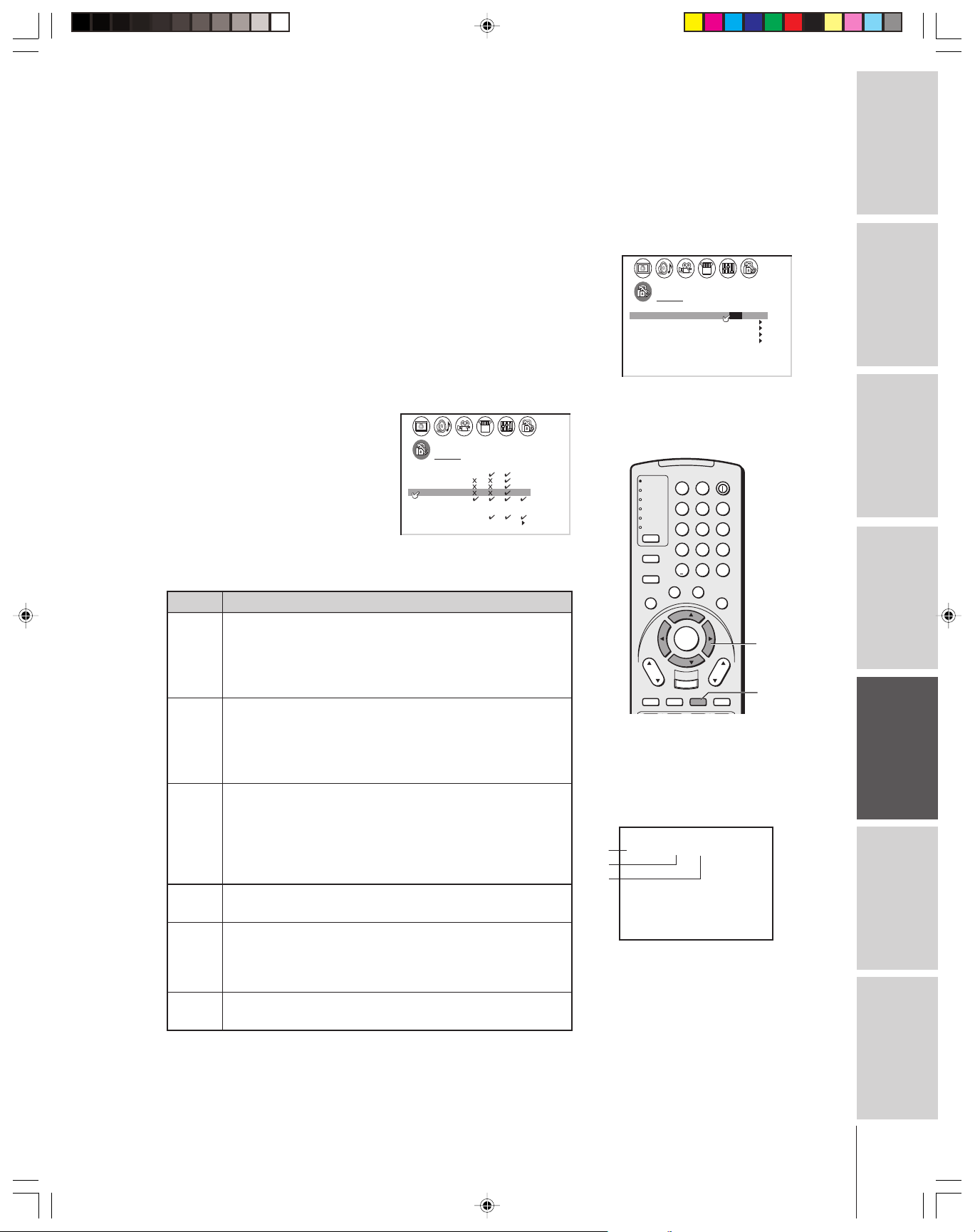
TV
CABLE/SAT
VCR
DVD
AUDIO1
AUDIO2
123
456
789
100/
0
ENT
POWER
+10
ACTION
MODE
PIC SIZE
MENU
LIGHT SLEEP
ENTER
FAV
CH
VOL
EXIT
CH RTN
DVD RTN
DVD CLEAR
SLOW/DIR
SKIP/SEARCH
INPUT
RECALL
MUTE
L
I
N
K
T
H
E
A
T
E
R
F
A
V
O
R
I
T
E
I
N
F
O
G
U
I
D
E
S
E
T
U
P
T
I
T
L
E
S
U
B
T
I
T
L
E
A
U
D
I
O
FAV
Using the V-CHIP menu
Some TV programs and movies include signals that classify the
content of the program (violence, sex, dialog, language). The V-CHIP
conrol feature in this TV detects the signals and blocks the programs
according to your selections. To use this feature, perform the
following setup.
Note:
The V-Chip function is available only for the
U.S. V-Chip system. The Canadian V-Chip
system is not supported.
Introduction
ENABLE BLOCKING
LOCKS menu
1. From the LOCKS menu, select ENABLE BLOCKING.
2. Press x or • to select ON or OFF.
ON : To enable your setting (Lock)
OFF: To release your setting (Unlock)
Note: The CH LOCK function is not affected by the Enable Blocking Setting.
TV RATING (Independent rating system for
broadcasters)
1. From the LOCKS menu, select TV RATING.
To select each item:
LOCKS
VCHIP–
ENABLE
BLOCK ING
TV RAT
ING
MPAA
RAT I NG
BLOCK ING OPT I ON
LOCKCH
VI LOCKDEO
GAME TIMER
FRONT PANEL LOCK
NEW
PIN CODE
Press z or y .
ON /
OFF
OFF
OFF
OFF
your TV
Connecting
2. Press x or • to display
the TV RATING menu.
3. Press z or y to select an item.
4. Press • to lock (display “X” ).
Press x to unlock (display “✓ ”).
5. Repeat steps 3 and 4 to set
LOCKS
TV RAT I NG MA PG G
DIALOG
LANGUAGE
SEX
OLENCE
VI
DLSVNO
YOUTH TV RAT NGI
VCHIP MENU–
1 4
Y7FV Y7 Y
Using the
Remote Control
the next item.
The TV age-based ratings and content themes you can lock are listed
in the table below.
Ratings Description and Content themes
MA Mature Audience Only (This program is specifically
designed to be viewed by adults and therefore may be
yzx •
your TV
Setting up
unsuitable for children under 17.)
L) Crude or indecent language S) Explicit sexual activity
V) Graphic violence
RECALL
14 Parents Strongly Cautioned (This program contains some
material that many parents would find unsuitable for
children under 14 years of age.)
D) Intensely suggestive dialog L) Strong, coarse language
S) Intense sexual situations V) Intense violence
PG Parental Guidance Suggested (This program contains
material that parents may find unsuitable for younger
children.)
D) Some suggestive dialog L) Infrequent coarse
language S) Some sexual situations V) Moderate
violence
Press RECALL to display the rating of
the TV program you are currently
watching.
STEREO
SAP
TV L VPG–
PG
L
V
Features
Using the TV’s
GGeneral Audience (Most parents would find this program
ANT
33 34 35
1
6
Appendix
suitable for all ages.)
Y7, Directed to Older Children (This program is designed for
NORMAL
CABLECLOCK 9 : 2 5
Y7FV children age 7 and above. Note: Programs in which fantasy
violence may be more intense or more combative than other
programs in this category are designated Y7FV.)
Y All Children (This program is designed to be appropriate for
all children.)
Index
39
Page 40

MPAA RATING (Independent rating system for movies)
Introduction
your TV
Connecting
The movie ratings you can lock are described as follows:
Using the
Remote Control
BLOCKING OPTION
your TV
Setting up
MPAA UNRATED:
Features
Using the TV’s
1. From the LOCKS menu, select MPAA RATING.
2. Press x or • to display the MPAA RATING menu, then press z
or y to highlight MPAA RATING.
LOCKS
MPAA RAT I
NG
XRPGPG GNC17 1 3
VCHIP MENU–
3. Press • to lock (“X”) or press x to unlock (“✓”).
X:X-rated (For adults only)
NC17: Not intended for anyone 17 and under
R:Restricted (Under 17 requires accompanying parent or adult
guardian.)
PG13 : Parents Strongly Cautioned (Some material may be
inappropriate for children under 13)
PG : Parental Guidance Suggested (Some material may not be
suitable for children)
G:General Audience (Appropriate for all ages)
1. From the LOCKS menu, select BLOCKING OPTION.
2. Press x or • to display the BLOCKING OPTION menu,
then press y or z to select an item.
Press x or • to select ON (Lock) or OFF (Unlock) for unrated
programs in the MPAA rating system.
LOCKS
VCHIP–
ENABLE
BLOCK ING
TV RAT
ING
MPAA
RAT I NG
BLOCK ING OPT I ON
CH LOCK
V
I LOCKDEO
GAME TIMER
FRONT PANEL LOCK
NEW
PIN CODE
ON
OFF
OFF
OFF
LOCKS
BLOCK ING OPT ION
MPAA
UNRATED
TV NONE RATING
VCHIP MENU–
ON
OFF
/
OFF
LOCKS menu
LOCKS
VCHIP–
ENABLE
BLOCK ING
TV RAT
ING
MPAA
RAT I NG
BLOCK ING OPT I ON
CH LOCK
V
I LOCKDEO
GAME TIMER
FRONT PANEL LOCK
PIN CODE
NEW
To select each item:
Press z or y .
TV
LIGHT SLEEP
CABLE/SAT
VCR
DVD
123
AUDIO1
AUDIO2
456
MODE
789
PIC SIZE
+10
100/
U
P
O
F
N
I
L
T
I
T
ENTER
DVD CLEAR
INPUT
F
S
U
E
FAV
FAV
EXIT
0
A
V
O
R
I
T
E
B
T
I
T
L
E
RECALL
SKIP/SEARCH
ACTION
MENU
E
D
I
U
G
E
S
CH
DVD RTN
CH RTN
SLOW/DIR
T
POWER
A
U
D
VOL
ENT
T
L
I
O
MUTE
ON
OFF
OFF
OFF
H
E
A
T
E
I
N
R
K
yzx •
Appendix
Index
40
TV NONE RATING
Press x or • to select ON (Lock) or OFF (Unlock) for programs
rated NONE in the TV PARENTAL GUIDELINES.
LOCKS
BLOCK INGNGOPTI ON
MPAA
UNRATED
TV NONE RATING
V
CH I
P MENU–
NOTE :ENABL
OPT
ION MAY BLOCK
EMERGENCY MESSAGES
ISITH
ON
ON
/
OFF
V-CHIP MENU:
Press x or • to return to the LOCKS menu.
Caution:
Setting the TV None Rating to ON may block
the broadcast of emergency information.The
menu will display the note, “Enabling this
option may block emergency messages” to
warn you of this possibility.
Page 41

Unlocking programs temporarily
If you try to watch a TV program that exceeds the rating limits you
set, the TV enters program lock mode. After 4 seconds, the TV starts
the auto favorite channel search function (see page 37). You can either
unlock the program temporarily or select a non-locked program to
watch.
THIS PROGRAM HAS BEEN BLOCKED!
TV
PG L V–
EXCEEDS
SET L I M I TS
PUSH MUTE TO ENTER
INP
CABLE
9
After 4 seconds
3456
TH IS PROGRAM
HAS BEEN BLOCKED !
PG L V–
TV
EXCEEDS
SET L I M I TS
PUSH MUTE
TO ENTER
INP
9
CABLE
7
8
To temporarily unlock the program:
1. Press MUTE.
2. Press the Number buttons (0–9) to enter your 4-digit PIN code.
BLOCK ACT
ING I VE
ENTER
IN
CODEP
I
TO TEMPORAR
0–9 TO SELECT ENTER: TO S ET:
UN–BLOCKLY
––––
3. Press ENTER.
If the correct code is entered, the program lock mode is released
and the normal picture appears.
All locking is disabled until the TV is turned off, and will be
enabled when the TV is turned on again.
TV
CABLE/SAT
VCR
DVD
AUDIO1
AUDIO2
MODE
PIC SIZE
ACTION
MENU
E
D
I
U
G
P
U
T
E
S
CH
DVD RTN
CH RTN
SLOW/DIR
LIGHT SLEEP
123
456
789
+10
100/
0
F
A
V
O
O
R
F
I
N
I
S
U
B
E
L
T
T
I
T
I
L
T
FAV
ENTER
FAV
EXIT
DVD CLEAR
INPUT
RECALL
SKIP/SEARCH
Introduction
your TV
Connecting
POWER
Channel
Number
Using the
ENT
T
E
T
H
E
A
T
L
E
I
N
R
K
E
A
U
D
I
O
ENTER
yzx •
VOL
MUTE
MUTE
Remote Control
your TV
Setting up
Locking channels
With the CH LOCK feature, you can lock specific channels. You will
not be able to tune locked channels with the Channel y z buttons or
Channel Number buttons unless you clear the setting.
You can lock a maximum of nine channels.
To lock channels:
1. From the LOCKS menu, select CH LOCK.
2. Press x or • to display the CH LOCK menu.
CH INPUT will be highlighted.
3. Press the Channel Number buttons to enter the channel you
want to lock.
4. Press ENTER.
LOCKS
VCHIP–
ENABLE
BLOCK ING
TV RAT
ING
MPAA
RATI NG
BLOCK I NG OPTIION
LOCK
VCHI LOCK
DEO 0 0 0
GAME TIMER
FRONT PANEL LOCK
NEW
PIN CODE
OFF
CH NPUT
000
0
CLEAR ALL
12
00
TV CABLE
5. Repeat steps 3 and 4 for other channels.
LOCKS
VCHIP–
ENABLE
BLOCKI NG
TV RAT
ING
MPAA
RATI NG
BLOCK ING
LOCK
VCHI LOCK
DEO 2100
GAME TIMER
FRONT PANEL LOCK
NEW
PIN CODE
OPTION
OFF
I
CH NPUT
000
0
CLEAR ALL
00
TV CABLE
LOCKS menu
LOCKS
VCHIP–
ENABLE
BLOCK ING
TV RAT
ING
MPAA
RAT I NG
BLOCK ING OPT I ON
LOCK
VCHI LOCK
DEO OFF
GAME TIMER
FRONT PANEL LOCK
NEW
PIN CODE
To select each item:
Press z or y .
ON
OFF
OFF
Features
Using the TV’s
Appendix
Index
(continued on next page)
41
Page 42

Introduction
To unlock individual channels:
1. From the LOCKS menu, select CH LOCK.
2. Press x or • to display the CH LOCK menu.
3. Press yzx • to highlight the channel you want to unlock, then
press ENTER.
your TV
Connecting
To unlock all locked channels at once:
Using the
Remote Control
Locking video inputs
your TV
Setting up
Features
Using the TV’s
With the VIDEO LOCK feature, you can lock out the input sources
(VIDEO 1, VIDEO 2, VIDEO 3, ColorStream HD1, ColorStream
HD2, DVI/HDCP) and channels 3 and 4.
You will not be able to select the input sources with the TV/VIDEO
button or Channel buttons unless you clear the setting.
To set up the video lock:
LOCKS
VCHIP–
ENABLE
BLOCK ING
TV RAT
ING
MPAA
RAT ING
BLOCK INGOPT ION
LOCK
VCHI LOCK
DEO 21338162
GAME TIMER
FRONT PANEL LOCK
NEW
PIN CODE
ON
I
CH NPUT
0
CLEAR ALL
TV CABLE
00
00
LOCKS
VCHIP–
ENABLE
BLOCK ING
TV RAT
ING
MPAA
RATI NG
BLOCK ING OPT ION
LOCK
VCHI LOCK
DEO
GAME TIMER
FRONT PANEL LOCK
NEW
PIN CODE
ON
I
CH NPUT
12 18 33
000
0
CLEAR ALL
TV CABLE
4. Repeat step 3 for other channels.
Press y or z to highlight CLEAR ALL, and then press x or •.
LOCKS
VCHIP–
ENABLE
BLOCK ING
TV RAT
ING
MPAA
RAT ING
BLOCK INGOPT ION
LOCK
VCHI LOCK
DEO
GAME TIMER
FRONT PANEL LOCK
NEW
PIN CODE
ON
I
CH NPUT
CH NPUT
000
000
0
CLEAR ALL
CLEAR ALL
00
TV CABLE
1. From the LOCKS menu, select VIDEO LOCK.
2. Press x or • to highlight the level of video locking you want
(Video, Video+, or Off), as follows:
VIDEO : Locks VIDEO 1, VIDEO 2, VIDEO 3, ColorStream
HD1, HD2, and DVI/HDCP.
00
TV
CABLE/SAT
VCR
DVD
AUDIO1
AUDIO2
MODE
PIC SIZE
ACTION
MENU
E
D
I
U
G
P
U
T
E
S
CH
DVD RTN
CH RTN
SLOW/DIR
LIGHT SLEEP
123
456
789
+10
100/
0
F
A
V
O
O
R
F
I
N
I
S
U
B
E
L
T
T
I
T
I
L
T
E
FAV
ENTER
FAV
EXIT
DVD CLEAR
INPUT
RECALL
SKIP/SEARCH
POWER
ENT
T
E
T
H
E
A
T
L
E
I
N
R
K
A
U
D
I
O
ENTER
yzx •
VOL
MUTE
Appendix
Index
42
VIDEO+ : Locks VIDEO 1, VIDEO 2, VIDEO 3, ColorStream,
HD1/HD2, DVI/HDCP, and channels 3 and 4. This
option should be used if you use the antenna terminal
to play a video tape.
Note: Make sure the POP is not on channel 3 or 4.
OFF : Unlocks all video input sources.
LOCKS
VCHIP–
ENABLE
BLOCK ING
TV RAT
ING
MPAA
RAT I NG
BLOCK ING OPT I ON
LOCK
VCHI LOCK
DEO VI /DEO VI+DEO / OFF
GAME TIMER
FRONT PANEL LOCK
NEW
PIN CODE
ON
OFF
OFF
Page 43

Using the game timer
You can use the game timer to set a time limit for playing a video game
(30-120 minutes). When the game timer is activated, the TV enters
VIDEO LOCK mode and locks out the input source for the video game
device.
To set the game timer:
1. From the LOCKS menu, select GAME TIMER.
2. Press x or • to select the length of time until the video mode is
blocked from among 30, 60, 90 and 120 minutes. When the
number is highlighted, the timer will start countdown.
LOCKS
VCHIP–
ENABLE
BLOCK ING
TV RAT
ING
MPAA
RAT I NG
BLOCK ING OPT I ON
LOCK
VCHI LOCK
DEO
GAME TIMER
FRONT PANEL LOCK
NEW
PIN CODE
ON
OFF
//OFF 30 60/ 90 / 120
OFF
To cancel the timer:
Select OFF in step 2 above.
Using the front panel lock feature
You can lock the front panel buttons to prevent your settings from
being changed accidentally (by children, for example). When the
front panel lock is in ON, all control buttons on the TV front panel
(except POWER) do not operate.
To lock the front panel:
1. From the LOCKS menu, select FRONT PANEL LOCK.
2. Press x or • to highlight ON.
Note:
• When one minute is left on the game timer,
the message “1 minute remaining” will
appear on-screen.
• To deacivate the game timer, set the
VIDEO LOCK to OFF (see “Locking video
inputs” on page 42).
TV front panel
DEMO MENU TV/VIDEO VOLUME CHANNEL
Buttons to be locked
TV front panel
Introduction
your TV
Connecting
Using the
Remote Control
your TV
Setting up
LOCKS
VCHIP–
ENABLE
BLOCK ING
TV RAT
ING
MPAA
RAT I NG
BLOCK ING OPT I ON
LOCK
CH
VI LOCKDEO
GAME TIMER OFF
FRONT RANEL LOCK
NEW
PIN CODE
ON
VIDEO
ON /
OFF
If a button on the front panel is pressed, the message “Not
Available” appears.
To unlock the front panel:
Highlight OFF in step 2 above, or press and hold the VOL x
button on the TV for about 10 seconds until the message “Front
Panel Lock: Off” appears on the screen.
Changing the PIN code
1. From the LOCKS menu, select NEW PIN CODE.
2. Press the Number buttons (0–9) to enter a 4-digit code.
The numbers you enter will replace the dashes in the display.
LOCKS
VCHIP–
ENABLE
BLOCK ING
TV RAT
ING
MPAA
RAT I NG
BLOCK ING OPT I ON
CH
LOCK
V
I LOCK
DEO V
GAME TIMER
FRONT RANEL LOCK
NEW P I N
CODE
ON
OFF
OFF
2562
I DEO
DEMO MENU TV/VIDEO VOLUME CHANNEL
VOL x
TV
CABLE/SAT
VCR
DVD
AUDIO1
AUDIO2
MODE
PIC SIZE
ACTION
MENU
E
D
I
U
G
P
U
T
E
S
CH
DVD RTN
CH RTN
SLOW/DIR
I
F
N
T
INPUT
POWER
LIGHT SLEEP
123
456
789
+10
100/
ENT
0
F
A
V
O
O
R
I
T
E
S
U
B
E
L
T
T
I
T
I
L
E
A
U
D
I
FAV
ENTER
FAV
VOL
EXIT
DVD CLEAR
RECALL
MUTE
SKIP/SEARCH
Number
T
H
E
A
T
L
E
I
N
R
K
O
ENTER
yzx •
Features
Using the TV’s
Appendix
Index
3. Press ENTER. The new PIN code is now active.
43
Page 44

Adjusting the picture
Selecting the picture mode
Introduction
You can select your desired picture type from four picture modes:
Sports, Standard, Movie, and Preference.
your TV
Connecting
To select the picture mode:
Using the
Remote Control
Mode Picture Quality
Sports Bright and dynamic picture (factory setting)
Standard Standard picture setting (factory setting)
Movie Movie-like picture setting (factory setting)
Preference Your personal preference*
*(see “Saving your new preferences” on page 45.)
1. Press MENU, and then press x or • until the PICTURE menu
appears.
2. Press z or y to select MODE.
3. Press x or • to highlight the mode you prefer.
P CTURE ANTENNAI
MODE
SPORTS STANDARD MOV I E///
CONTRAST
BR GHTNESSI
COLOR
TINT
SHARPNESS
RESET
SAVE NEW
PREFERENCE
80
50
50
50
PREFERENCE
0
Note:
If you select one of the factory-set picture
modes (SPORTS, STANDARDS, or MOVIE)
and then change a picture quality setting (for
example, increase the contrast), the picture
mode automatically changes to
PREFERENCE in the Picture menu.
To save your new picture quality settings, you
must select SAVE NEW PREFE RENCE (see
page 45) before closing the Picture menu or
the TV will return to the previous picture
mode.
TV front panel
DEMO MENU TV/VIDEO VOLUME CHANNEL
MENU
x •zy
your TV
Setting up
Features
Using the TV’s
Appendix
Adjusting the picture quality
You can adjust the picture quality to your personal preferences,
including the contrast, brightness, color, tint, sharpness, flesh tone,
noise reduction and color temperature.
Selection x Pressing •
contrast lower higher
brightness darker lighter
color paler deeper
tint reddish greenish
sharpness softer sharper
To adjust the picture quality:
1. Press MENU, and then press x or • until the PICTURE menu
appears.
2. Press z or y until the item you want to adjust is highlighted.
3. Press x or • to adjust the level.
P CTURE ANTENNAI
MODE PREFERENCE
CONTRAST
BR GHTNESSI
COLOR
TINT
SHARPNESS
RESET
SAVE
NEW
75
50
50
0
50
PREFERENCE
TV
CABLE/SAT
VCR
DVD
AUDIO1
AUDIO2
MODE
PIC SIZE
ACTION
MENU
E
D
I
U
G
P
U
T
E
S
CH
DVD RTN
CH RTN
SLOW/DIR
LIGHT SLEEP
123
456
789
+10
100/
0
F
A
V
O
O
R
F
I
N
I
S
U
B
E
L
T
T
I
T
I
L
T
E
FAV
ENTER
FAV
EXIT
DVD CLEAR
INPUT
RECALL
SKIP/SEARCH
POWER
ENT
T
E
T
L
A
U
D
I
O
MENU
H
E
A
T
E
I
N
R
K
yzx •
VOL
MUTE
Index
The PICTURE qualities you adjusted can be saved in the TV’s
memory with the SAVE NEW PREFERENCE feature (see page 45).
You can keep these settings or choose factory set options, as described
under “Selecting the picture mode” above.
44
Page 45

Saving your new preferences
You can save the PICTURE qualities (contrast, brightness, color, tint,
and sharpness) you adjusted in the picture preference mode.
To save your new preferences:
1. Press MENU, and then press x or • until the PICTURE menu
appears.
2. Press y or z to highlight SAVE NEW PREFERENCE.
3. Press x or •. When complete, the menu displays “DONE.”
P CTURE ANTENNAI
MODE PREFERENCE
CONTRAST
BR GHTNESSI
COLOR
TINT
SHARPNESS
RESET
NEW
SAVE
75
50
50
0
50
PREFERENCE DONE
The mode automatically change to PREFERENCE (see “Selecting the
picture mode” on page 44).
TV
CABLE/SAT
VCR
DVD
AUDIO1
AUDIO2
MODE
PIC SIZE
ACTION
MENU
E
D
I
U
G
P
U
T
E
S
CH
DVD RTN
CH RTN
SLOW/DIR
LIGHT SLEEP
123
456
789
+10
100/
0
F
A
V
O
O
R
F
I
N
I
S
U
B
E
L
T
T
I
T
I
L
T
FAV
ENTER
FAV
EXIT
DVD CLEAR
INPUT
RECALL
SKIP/SEARCH
POWER
Introduction
ENT
T
E
E
A
U
D
I
VOL
MUTE
MENU
T
H
E
A
T
L
E
I
N
R
K
O
yzx •
your TV
Connecting
Using the flesh tone feature
This feature displays natural flesh tones by correcting the tint.
To turn on the flesh tone feature:
1. Press MENU, and then press x or • until the PICTURE menu
appears.
2. Press y or z to highlight FLESH TONE.
3. Press x or • to highlight ON.
P CTURE ANTENNAI
MODE PREFERENCE
FLESH TONE ON
CableClear DNR
SVM
COLOR
TEMPERATURE
DISPLAY FORMAT
SAVE NEW
OFF
HIGH
MEDI UM
1080 i
PREFERENCE
OFF/
Using the CableClear™ DNR feature
This feature allows you to reduce visible interference in your TV
picture. This is useful when receiving a broadcast with a weak signal
(especially a Cable channel) or playing back a video cassette or disc
damaged by repeated use.
To turn on CableClear™ DNR:
1. Press MENU, and then press x or • until the PICTURE menu
appears.
2. Press y or z to highlight CableClear DNR.
3. Press x or • to highlight AUTO.
Note:
• CableClear DNR is not available in DVI
mode (fixed to OFF).
• The “CableClear DNR” menu listing will
change to “DNR” in ColorStream mode.
Using the
Remote Control
your TV
Setting up
Features
Using the TV’s
Appendix
P CTURE ANTENNAI
MODE
FLESH TONE ON
CableClear DNR
SVM
COLOR
TEMPERATURE
DISPLAY FORMAT
SAVE
NEW
PREFERENCE
HIGH
MEDI UM
1080 i
PREFERENCE
/
OFFAUTO
To turn off CableClear DNR:
Highlight OFF in step 3 above.
Index
45
Page 46

Selecting the color temperature
You can change the quality of the picture by selecting from three
preset color temperatures: cool, medium, and warm.
Introduction
To select the color temperature:
your TV
Connecting
Resetting your picture adjustments
The RESET function adjusts the picture qualities you adjusted to the
following factory settings:
Using the
Remote Control
your TV
Setting up
To reset your picture adjustments:
1. Press MENU, and then press x or • until the PICTURE menu
appears.
2. Press y or z to highlight COLOR TEMPERATURE.
3. Press x or • to highlight the mode you prefer.
Mode Picture Quality
P CTURE ANTENNAI
MODE PREFERENCE
FLESH TONE ON
CableClaar DNR
SVM
COLOR
TEMPERATURE
DISPLAY FORMAT
SAVE
NEW
AUTO
HIGH
COOL MED UM WARMI//
1080 i
PREFERENCE
cool blueish
medium neutral
warm reddish
Contrast ................ max (100)
Brightness ............ center (50)
Color ................... center (50)
Tint ....................... center (0)
Sharpness ............. center (50)
Color temperature........... cool
CableClear DNR ........... auto
SVM .............................. high
Mode ........................... sports
1. Press MENU, and then press x or • until the PICTURE menu
appears.
2. Press y or z to highlight RESET.
3. Press x or •. The menu displays “DONE.”
TV
CABLE/SAT
VCR
DVD
AUDIO1
AUDIO2
MODE
PIC SIZE
ACTION
MENU
E
D
I
U
G
P
U
T
E
S
CH
DVD RTN
CH RTN
SLOW/DIR
LIGHT SLEEP
123
456
789
+10
100/
0
F
A
V
O
O
R
F
I
N
I
S
U
B
E
L
T
T
I
T
I
L
T
E
FAV
ENTER
FAV
EXIT
DVD CLEAR
INPUT
RECALL
SKIP/SEARCH
POWER
ENT
T
E
T
L
A
U
D
I
O
MENU
H
E
A
T
E
I
N
R
K
yzx •
VOL
MUTE
Features
Using the TV’s
Appendix
Index
46
P CTURE ANTENNAI
MODE SPORTS
CONTRAST
BR GHTNESSI
COLOR
TINT
SHARPNESS
RESET
SAVE NEW
100
50
50
50
PREFERENCE
0
DONE
Page 47

Selecting the Scan Velocity Modulation (SVM)
The SVM feature enhances picture contrast and sharpness. This
feature has three modes: HIGH, LOW, and OFF.
To select the SVM feature:
1. Press MENU, and then press x or • until the PICTURE menu
appears.
2. Press y or z to highlight “SVM”.
3. Press x or • to highlight the mode you prefer (HIGH, LOW, or
OFF).
P CTURE ANTENNAI
MODE
FLESH TONE OFF
CableClear DNR
SVM
COLOR
TEMPERATURE
DISPLAY FORMAT
SAVE
NEW
PREFERENCE
OFF
H
MEDI UM
1080 i
PREFERENCE
I
GH
LOW OFF
//
Selecting the display format (for 480p signals only)
This feature converts a 480p input signal to 540p or 1080i.
To select the display format:
1. Press MENU, and then press x or • until the PICTURE menu
appears.
2. Press y or z to highlight DISPLAY FORMAT.
3. Press x or • to select 540p or 1080i.
P CTURE ANTENNAI
MODE
FLESH TONE OFF
CableClear DNR
SVM
COLOR
TEMPERATURE
DISPLAY FORMAT
SAVE
NEW
MOVIE
AUTO
HIGH
MEDI UM
PREFERENCE
1080 i540P/
Note:
SVM is not required when viewing some
high-quality video material. If you are
watching high-quality video material, you may
want to set SVM to OFF.
TV
CABLE/SAT
VCR
DVD
AUDIO1
AUDIO2
MODE
PIC SIZE
ACTION
MENU
E
D
I
U
G
P
U
T
E
S
CH
DVD RTN
CH RTN
SLOW/DIR
I
F
N
T
INPUT
POWER
LIGHT SLEEP
123
456
789
+10
100/
ENT
0
F
A
V
O
O
R
I
T
E
S
U
B
E
L
T
T
I
T
I
L
E
A
U
D
I
FAV
ENTER
FAV
VOL
EXIT
DVD CLEAR
RECALL
MUTE
SKIP/SEARCH
MENU
T
H
E
A
T
L
E
I
N
R
K
O
yzx •
Note:
• The DISPLAY FORMAT feature is available
only for 480p input. 1080i is always output
when a signal other than 480p is input.
• If you notic flickering in a 480p image, try
setting the DISPLAY FORMAT to 540p.
Introduction
your TV
Connecting
Using the
Remote Control
your TV
Setting up
47
Features
Using the TV’s
Appendix
Index
Page 48

Selecting the video input source
Press INPUT on the remote control or TV/VIDEO on the TV front
panel to view a signal from another device connected to your TV, such as
Introduction
a VCR or video disc player (see illustrations below). You can select ANT
1, VIDEO 1, VIDEO 2, VIDEO 3, ColorStream HD1, ColorStream
HD2, DVI, or ANT 2 depending on which input jacks you used for
connecting your devices (see “Connecting your TV” on page 7).
your TV
Connecting
Labeling the video input sources
SELECT ION
SOURCE
0:
ANT 1
1:
VIDEO 1
2:
VIDEO 2
I DEO
3
V
3:
4:
CSooltreamr
5:
CSooltreamr
:
6
DVI
:
7
ANT 2
-
7 TO SELECT:
0
HD1
HD2
Pressing INPUT on the remote control
displays the current signal source
(press INPUT again or
0-7 to change)
SOURCE
SELECT ION
ANT 1
VIDEO 1
VIDEO 2
V
I DEO
3
CSooltreamr
CSooltreamr
DVI
ANT 2
:
TV / V I DEO TO SELECT
HD1
HD2
Pressing TV/VIDEO on the TV changes
the current signal source
Note:
When ColorStream HD 1 or HD 2 is selected,
the VIDEO OUT jack does not output a signal.
To receive a video OUT signal, use a video or
S-video IN connection instead of the
ColorStream connection.
Please note the following regarding
the DVI source selection:
This TV is not intended for connection
to and should not be used with a PC
(personal computer). See “Connecting
a device to the DVI/HDCP input” on
page 13 for details.
Using the
Remote Control
your TV
Setting up
Features
Using the TV’s
Appendix
Index
The VIDEO LABEL feature allows you to label each input source for
your TV from the following preset list of labels:
–: Uses the default label name
VCR: Video cassette recorder
DVD: DVD video
DTV : Digital TV set-top box
SAT : Satellite box
CBL : Cable box
HD : DVI/HDCP device (see page 13.)
To label the video input sources:
1. Press MENU, and then press x or • until the CUSTOM menu
appears.
2. Press y or z to highlight VIDEO LABEL.
CUSTOM
TIMER
ON
SLEEP
CC C2
FAVOR I CH
FAVOR I CH2TE
LABEL
CH
V
I
DEO
BACKGROUND
I
LABEL
00h00m
0h00m
OFF
1TE
NG
3. Press x or • to display the VIDEO LABEL menu.
4. Press y or z to highlight the video source you want to label.
5. Press x or • to select the desired label for that input source.
CUSTOM
IV DEO
LABEL
MENU
HD1
HD2
–
VCR/ DVD/ DTV/ SAT CBL/
–
–
–
–
–
I1V DEO
I2V DEO
I3V DEO
Color Stream
Color Stream
DVI
CUSTOM
6. Finish labeling the other video sources as desired. To return to the
previous menu, press y or z to highlight CUSTOM MENU,
and then press x or •.
7. To exit the menu, press EXIT.
TV front panel
DEMO MENU TV/VIDEO VOLUME CHANNEL
TV/VIDEO
TV
CABLE/SAT
VCR
DVD
AUDIO1
AUDIO2
MODE
PIC SIZE
ACTION
MENU
E
D
I
U
G
P
U
T
E
S
CH
DVD RTN
CH RTN
SLOW/DIR
I
F
N
T
INPUT
POWER
LIGHT SLEEP
123
456
789
+10
100/
0
F
A
V
O
O
R
I
T
E
S
U
B
E
L
T
T
I
T
I
L
E
A
U
D
FAV
ENTER
FAV
VOL
EXIT
DVD CLEAR
RECALL
SKIP/SEARCH
ENT
T
L
I
O
MUTE
Number
MENU
H
E
A
T
E
I
N
R
K
yzx •
EXIT
INPUT
Note:
The HD (high-definition) label is available for
DVI mode only (see “Selecting the video
input source” above, and “Connecting a
device to the DVI/HDCP input” on page 13).
48
Page 49
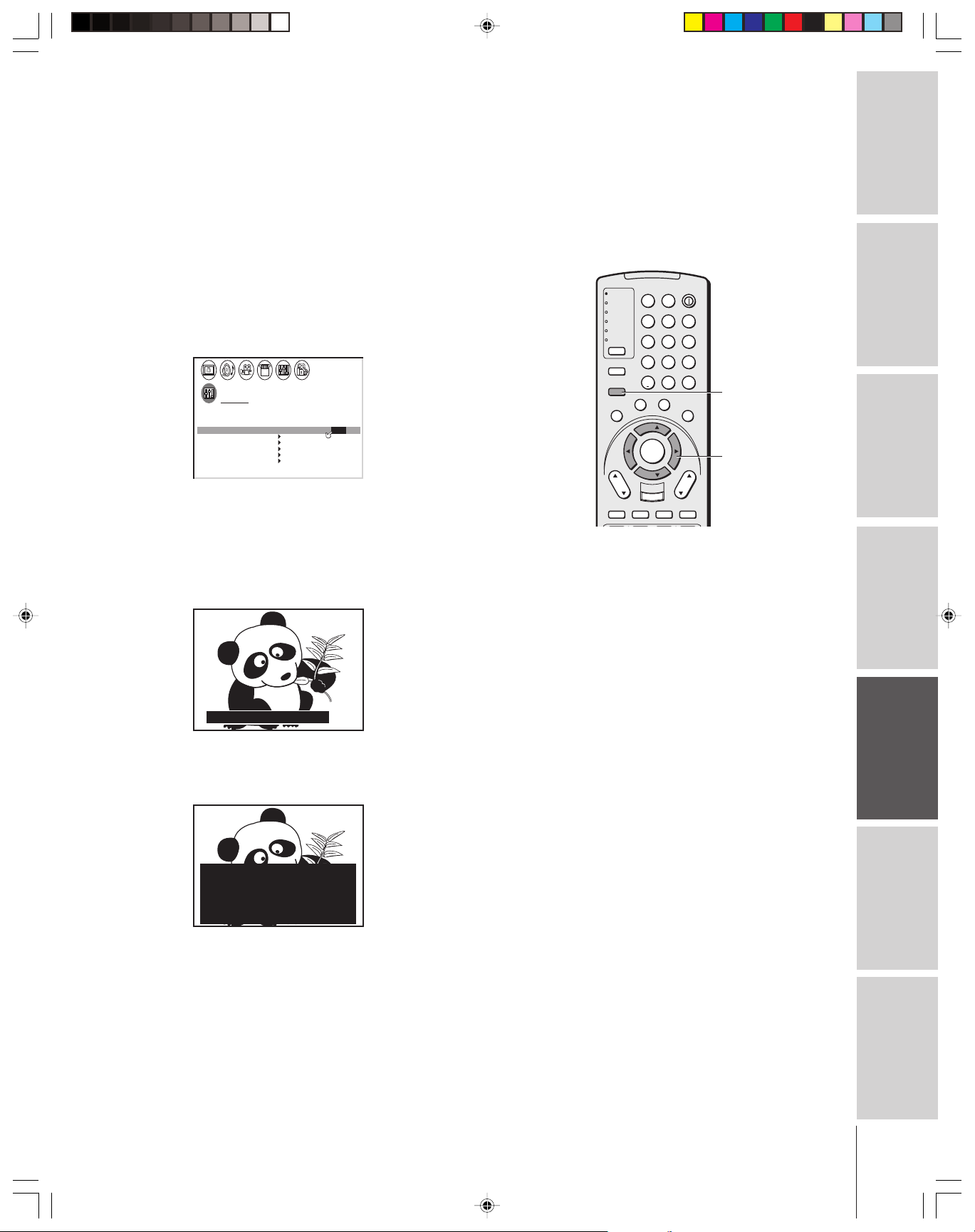
Using the closed caption feature
The closed caption feature has two options:
• Captions—An on-screen display of the dialogue, narration, and
sound effects of TV programs and videos that are closed
captioned (usually labled “CC”).
•Text—An on-screen display of information not related to the
current program, such as weather or stock data (when provided
by individual stations).
To view captions or text:
1. Tune the TV to the desired program.
2. Press MENU, and then press x or • to display CUSTOM menu.
3. Press y or z to highlight CC.
CUSTOM
TIMER
ON
SLEEP
CC C1 / C2 / C3 / C4/ T 1 /T 2 / T3 / T4 /
FAVOR I CH
FAVOR I CH2TE
LABEL
CH
V
I
DEO
BACKGROUND
4. Press x or • to highlight the desired closed caption mode, as
follows:
•To view captions, highlight C1, C2, C3, or C4 (C1 displays
translation in the primary language in your area).
Note: If the program or video you selected is not closed captioned,
Giant pandas eat leaves.
00h00m
I
LABEL
0h00m
1TE
NG
OFF
no captions will display on the screen.
TV
CABLE/SAT
VCR
DVD
AUDIO1
AUDIO2
MODE
PIC SIZE
ACTION
MENU
E
D
I
U
G
P
U
T
E
S
CH
DVD RTN
CH RTN
SLOW/DIR
I
F
N
T
INPUT
POWER
LIGHT SLEEP
123
456
789
+10
100/
ENT
0
F
A
V
O
O
R
I
T
E
S
U
B
E
L
T
T
I
T
I
L
E
A
U
D
I
FAV
ENTER
FAV
VOL
EXIT
DVD CLEAR
RECALL
MUTE
SKIP/SEARCH
MENU
T
H
E
A
T
L
E
I
N
R
K
O
yzx •
Note:
A closed caption signal may not display in the
following situations:
• when a videotape has been dubbed
• when the signal reception is weak
• when the signal reception is nonstandard
Introduction
your TV
Connecting
Using the
Remote Control
your TV
Setting up
•To view text, highlight T1, T2, T3, or T4.
Note: If text is not available in your area, a black rectangle may appear on
your screen. If this happens, turn the Closed Caption feature OFF.
WORLD WEATHER
Temps Current
F C Weather
LONDON 51 11
MOSCOW
PARIS
ROME
TOKYO
57 14
53 12
66 19
65 18
Clear
Cloudy
Clear
Cloudy
Rain
To turn off the Closed Caption feature:
Highlight OFF in step 4.
Features
Using the TV’s
Appendix
Index
49
Page 50

Setting the ON-timer
To set the ON timer to turn on the TV automatically:
Introduction
your TV
Connecting
Using the
Remote Control
Setting the sleep timer
To set the sleep timer to turn off the TV automatically:
your TV
Setting up
1. Press MENU, and then press x or • until the CUSTOM menu
appears.
2. Press y or z to highlight ON.
3. After the number position starts to blink, press the Number
buttons (0–9) to enter the length of time until the TV turns on
automatically.
You can set the ON timer in 10-minute increments, to a
maximum of 12 hours.
4. Press ENTER to start the timer.
CUSTOM
TIMER
ON
SLEEP
CC C2
FAVOR I CH
FAVOR I CH2TE
LABEL
CH
V
I
DEO
BACKGROUND
I
LABEL
10h30m
0h00m
OFF
1TE
NG
5. Press POWER to turn off the TV.
The TV will turn on automatically after the length of time you
set in the ON timer.
1. Press SLEEP to set the length of time until the TV turns off.
TV
CABLE/SAT
VCR
DVD
AUDIO1
AUDIO2
MODE
PIC SIZE
ACTION
MENU
E
D
I
U
G
P
U
T
E
S
CH
DVD RTN
CH RTN
SLOW/DIR
LIGHT SLEEP
123
456
789
+10
100/
0
F
A
V
O
O
R
F
I
N
I
S
U
B
E
L
T
T
I
T
I
L
T
E
FAV
ENTER
FAV
EXIT
DVD CLEAR
INPUT
RECALL
SKIP/SEARCH
POWER
ENT
T
E
T
L
A
U
D
I
O
VOL
MUTE
SLEEP
POWER
Number
MENU
H
E
A
T
E
I
N
R
K
ENTER
yzx •
Note :
When an instant power failure occurs, the ON
timer and sleep timer settings may be cleared.
To display the amount of time left until the TV
turns on or off automatically, press RECALL.
Features
Using the TV’s
Appendix
Index
T I MER
0
h 00m
Every time you press the button, the time display will increase in
10-minute increments, to a maximum of 3 hours.
0h00m → 0h10m → 0h20m 2h50m → 3h00m → 0h00m
To cancel the sleep timer:
Press SLEEP until it is set to 0h00m.
The timer also can be set using the on-screen menu:
1. Press MENU, and then press x or • until the CUSTOM menu
appears.
2. Press y or z to highlight SLEEP.
3. After the number position starts to blink, press the Number
buttons (0–9) to enter the length of time until the TV turns off
automatically.
4. Press ENTER to start the timer.
CUSTOM
TIMER
ON
SLEEP
CC C1
FAVOR I CH1TE
FAVOR I CH2TE
LABEL
CH
V
I DEO
BACKGROUND
I
LABEL
00h00m
2h00m
NG
50
Page 51
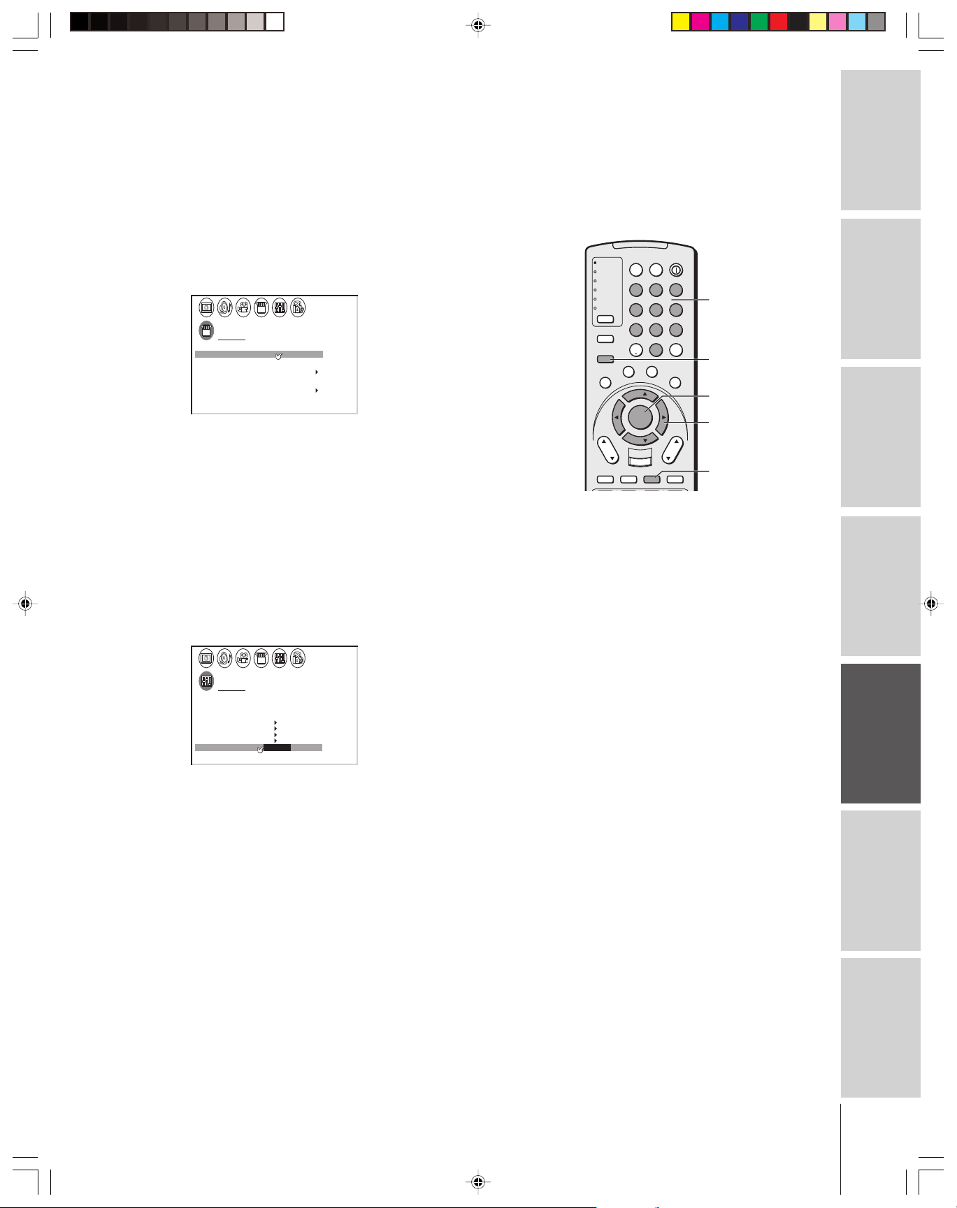
Setting the clock
To set the clock:
1. Press MENU, and then press x or • until the SET UP menu
appears.
2. Press y or z to highlight CLOCK SET.
3. After the number position starts to blink, press the Number
buttons (0–9) to enter the correct time. The clock operates on a
24-hour cycle only.
4. Press ENTER to start the clock.
SET UP
LANGUAGE
CLOCK
SET
ANT
1 ANT
TV
PROGRAM
CH
ADD ADDERASE/
T I L T CORRECT I ON
QU I C K CONNECT GU I DE
I
ENGL SH
09 2 5:
1/2
CABLE/ CABLE
0
To display the time on-screen:
Press RECALL.
Selecting the background of the menu display
You can change the background of the menu display by selecting from
two preset types: shaded and solid (gray).
To select the menu background:
1. Press MENU, and then press x or • until the CUSTOM menu
appears.
2. Press y or z to highlight BACKGROUND.
3. Press x or • to select either SHADED or SOLID.
Note :
If the TV’s power source is interrupted (the
power cord is unplugged or a power failure
occurs), the clock must be reset.
TV
CABLE/SAT
VCR
DVD
AUDIO1
AUDIO2
MODE
PIC SIZE
ACTION
MENU
E
D
I
U
G
P
U
T
E
S
CH
DVD RTN
CH RTN
SLOW/DIR
I
F
N
T
INPUT
POWER
LIGHT SLEEP
123
456
789
+10
100/
ENT
0
F
A
V
O
O
R
I
T
E
S
U
B
E
L
T
T
I
T
I
L
E
A
U
D
I
FAV
ENTER
FAV
VOL
EXIT
DVD CLEAR
RECALL
MUTE
SKIP/SEARCH
Number
MENU
T
H
E
A
T
L
E
I
N
R
K
O
ENTER
yzx •
RECALL
Introduction
your TV
Connecting
Using the
Remote Control
your TV
Setting up
CUSTOM
TIMER
ON
SLEEP
CC C 1
FAVOR I CH1TE
FAVOR I CH2TE
LABEL
CH
V
I DEO
BACKGROUND SHADED SOL I D/
I
LABEL
00h00m
0h00m
NG
Features
Using the TV’s
Appendix
Index
51
Page 52

Adjusting the sound
Muting the sound
Introduction
your TV
Connecting
Using the
Remote Control
your TV
Setting up
Press MUTE to temporarily reduce (1/2 MUTE) or turn off (MUTE)
the sound. While the sound is muted, the screen will display “1/2
MUTE” or “MUTE” in the lower right corner. Every time you press
MUTE, the mute mode will change in the following order.
When you select “MUTE” mode, the closed caption feature is
automatically activated (if the closed caption mode is set to OFF). To
deactivate this feature, deactivate MUTE. See “Using the closed
caption feature” on page 49 for more information.
Selecting stereo/SAP broadcasts
The multi-channel TV sound (MTS) feature allows you to output
high-fidelity stereo sound from your TV’s internal speakers. MTS also
can transmit a second audio program (SAP) containing a second
language, music, or other audio information (when provided by
individual stations).
When the TV receives a stereo or SAP broadcast, the word STEREO
or SAP appears on-screen every time the TV is turned on, the channel
is changed, or the RECALL button is pressed.
The MTS feature is not available when the TV is in VIDEO mode.
To listen to stereo sound:
→ Normal → 1/2 MUTE → MUTE
1. Press MENU, and then press x or • until the AUDIO menu
appears.
2. Press y or z to highlight MTS.
3. Press x or • to highlight STEREO.
TV
CABLE/SAT
VCR
DVD
AUDIO1
AUDIO2
MODE
PIC SIZE
ACTION
MENU
E
D
I
U
G
P
U
T
E
S
CH
DVD RTN
CH RTN
SLOW/DIR
I
F
N
T
INPUT
POWER
LIGHT SLEEP
123
456
789
+10
100/
0
F
A
V
O
O
R
I
T
E
S
U
B
E
L
T
T
I
T
I
L
E
A
U
D
FAV
ENTER
FAV
VOL
EXIT
DVD CLEAR
RECALL
SKIP/SEARCH
ENT
T
L
I
O
MUTE
MENU
H
E
A
T
E
I
N
R
K
yzx •
RECALL
MUTE
TV front panel
DEMO MENU TV/VIDEO VOLUME CHANNEL
MENU
x •zy
Features
Using the TV’s
Appendix
Index
AUD OI
MTS
BASS
TREBLE
BALANCE
RESET
STEREO SAP MONO//
50
50
0
The word “STEREO” or “SAP” displays in yellow in the menu
when the TV receives the signal.
You can leave your TV in STEREO mode because it will
automatically output the type of sound being broadcast (stereo or
monaural).
If the stereo sound is noisy, select MONO to reduce the noise.
To listen to SAP (if available):
1. Press MENU, and then press x or • until the AUDIO menu
appears.
2. Press y or z to highlight MTS.
3. Press x or • to highlight SAP. You will hear the station’s
secondaudio program (if available) from the speakers, while
viewing the original program’s picture (see note at right).
Note :
A second audio program (SAP) can be heard
only on those TV stations that offer it.
For example, a station might broadcast music
(or another language) as a second audio
program. If you have SAP on, you will see the
current program on the screen but hear
music (or another language) instead of the
program’s normal audio.
If you have SAP on and the station you are
watching is not broadcasting a second audio
program, the station’s normal audio will be
output.
Occasionally no sound is output in SAP
mode. If this happens, set the MTS feature to
STEREO mode.
52
Page 53

Enjoying the Dolby Virtual sound feature
The Dolby* Virtual sound feature allows you to enjoy virtual
surround sound from the TV’s speakers.
•If you connect a device (such as a game console, DVD player, or
DTV receiver) with analog audio output to standard (analog)
audio terminals on the TV, and the input source is encoded with
Dolby Surround
sound or Dolby Digital sound,
the Dolby Virtual feature functions as Virtual Dolby Surround
(VDS). VDS simulates Dolby Surround sound from the
TV’s speakers.
To turn on the Dolby Virtual sound feature:
1. Press MENU, and then press x or • until the THEATER menu
appears.
2. Press y or z to highlight Dolby Virtual.
3. Press x or • to highlight ON.
THEATER
Dolby Virtual
WOW
SRS 3D
FOCUS
TruBass
MAGE
SHAPE
I
AUTO ASPECT
C I NEMA MODE
ON OFF
/
OFF
OFF
ON OFF
OFF
FILM V I DEO
To turn off the Dobly Virtual sound feature:
Highlight OFF in step 3 above.
Note:
• The Dolby Virtual and SRS 3D features
cannot be on at the same time.
• If you use external speakers, see
“Connecting an A/V receiver” on page 14.
TV
CABLE/SAT
VCR
DVD
AUDIO1
AUDIO2
MODE
PIC SIZE
ACTION
MENU
E
D
I
U
G
P
U
T
E
S
CH
DVD RTN
CH RTN
SLOW/DIR
I
F
N
T
INPUT
POWER
LIGHT SLEEP
123
456
789
+10
100/
ENT
0
F
A
V
O
O
R
I
T
E
S
U
B
E
L
T
T
I
T
I
L
E
A
U
D
I
FAV
ENTER
FAV
VOL
EXIT
DVD CLEAR
RECALL
MUTE
SKIP/SEARCH
MENU
T
H
E
A
T
L
E
I
N
R
K
O
yzx •
Introduction
your TV
Connecting
Using the
Remote Control
your TV
Setting up
Features
Using the TV’s
Appendix
“Dolby” and the double-D symbol are trademarks of Dolby Laboratories.
Manufactured under license from Dolby Laboratories.
Index
53
Page 54

Using the WOW™ surround sound feature
WOW is a special combination of SRS Labs audio technologies that
creates a thrilling surround sound experience with deep, rich bass
Introduction
from stereo sound sources. Your TV’s will sound fuller, richer and
wider.
To adjust the WOW feature:
your TV
Connecting
Using the
Remote Control
1. Select STEREO mode (See “Selecting stereo/SAP broadcasts” on
page 52).
2. Press MENU, and then press x or • until the THEATER menu
appears.
3. Press y or z to highlight the desired WOW feature you want to
adjust, then press x or • to adjust the item.
• SRS 3D — To turn on or off the surround sound effect.
• FOCUS — To turn on or off the vocal emphasis effect.
•TruBass — To select your desired bass expansion level (HIGH,
LOW or OFF).
THEATER
Dolby Virtual
WOW
SRS 3D
FOCUS
TruBass
IMAGE SHAPE
AUTO ASPECT
C I NEMA MODE
OFF
ON
OFF
ON HIGH
OFF
VIDEO
OFF
/
TV
CABLE/SAT
VCR
DVD
AUDIO1
AUDIO2
MODE
PIC SIZE
ACTION
MENU
E
D
I
U
G
P
U
T
E
S
CH
DVD RTN
CH RTN
SLOW/DIR
I
F
N
T
INPUT
POWER
LIGHT SLEEP
123
456
789
+10
100/
0
F
A
V
O
O
R
I
T
E
S
U
B
E
L
T
T
I
T
I
L
E
A
U
D
FAV
ENTER
FAV
VOL
EXIT
DVD CLEAR
RECALL
SKIP/SEARCH
ENT
T
L
I
O
MUTE
MENU
H
E
A
T
E
I
N
R
K
yzx •
Note:
If the broadcast is monaural, the SRS 3D
effect does not work.
your TV
Setting up
Features
Using the TV’s
Appendix
Adjusting the sound quality
You can change the quality of your TV’s sound by adjusting the bass,
treble, and balance.
To adjust the sound quality:
1. Press MENU, and then press x or • until the AUDIO menu
appears.
2. Press y or z to highlight the item you want to adjust.
AUD OI
MTS
BASS
TREBLE
BALANCE
RESET
STEREO SAP MONO//
50
50
0
3. Press x or • to adjust the level.
• x makes the sound quality weaker or increases the balance in the
left channel, depending on the item selected.
• • makes the sound quality stronger or increases the balance in
the right channel, depending on the item selected.
Index
________
WOW, SRS and the symbol are trademarks of SRS Labs, Inc.
WOW technology is incorporated under license from SRS Labs, Inc.
54
Page 55

Resetting your audio adjustments
The RESET function returns your audio adjustments to the following
factory settings:
Bass .................. center (50)
Tr eble ............... center (50)
Balance ............ center (0)
To reset your audio adjustments:
1. Press MENU, and then press x or • until the AUDIO menu
appears.
2. Press y or z to highlight RESET.
3. Press x or •. The menu displays “DONE.”
AUD OI
MTS
BASS
TREBLE
BALANCE
RESET
STEREO
50
50
0
DONE
TV
CABLE/SAT
VCR
DVD
AUDIO1
AUDIO2
MODE
PIC SIZE
ACTION
MENU
E
D
I
U
G
P
U
T
E
S
CH
DVD RTN
CH RTN
SLOW/DIR
LIGHT SLEEP
123
456
789
+10
100/
0
F
A
V
O
O
R
F
I
N
I
S
U
B
E
L
T
T
I
T
I
L
T
FAV
ENTER
FAV
EXIT
DVD CLEAR
INPUT
RECALL
SKIP/SEARCH
POWER
Introduction
ENT
T
E
T
E
A
U
D
I
O
VOL
MUTE
MENU
H
E
A
T
L
E
I
N
R
K
yzx •
your TV
Connecting
Using the CYCLONE® sub-woofer system
Toshiba’s CYCLONE® ABX (Acoustic Bass eXpansion) system
provides dynamic acoustic reproduction in a self-enclosed bass-reflex
sub-woofer system.
®
To turn on the CYCLONE
sub-woofer system and adjust the
CYCLONE level:
1. Press MENU, and then press x or • until the AUDIO menu
appears.
2. Press y or z to highlight CYCLONE.
3. Press x or • to highlight ON.
AUD OI
CYCLONE
CYC LEVEL
SPEAKERS
AUD O OUTI
STABLE
SOUND
ON
70
ON
MA I N
OFF
OFF/
4. Press y or z to highlight CYC LEVEL.
5. Press x or • to adjust the CYCLONE level (sub-woofer volume).
Press • to increase the sub-woofer volume.
Press x to decrease the sub-woofer volume.
Note:
While the CYCLONE mode is OFF, if the
CYCLONE level is adjusted, the CYCLONE is
automatically turned ON.
Using the
Remote Control
your TV
Setting up
Features
Using the TV’s
AUD OI
CYCLONE
CYC LEVEL
SPEAKERS
AUD O OUTI
STABLE
SOUND
ON
70
ON
MA I N
OFF
To turn off the CYCLONE® sub-woofer system:
Highlight OFF in step 3 above.
Appendix
Index
55
Page 56
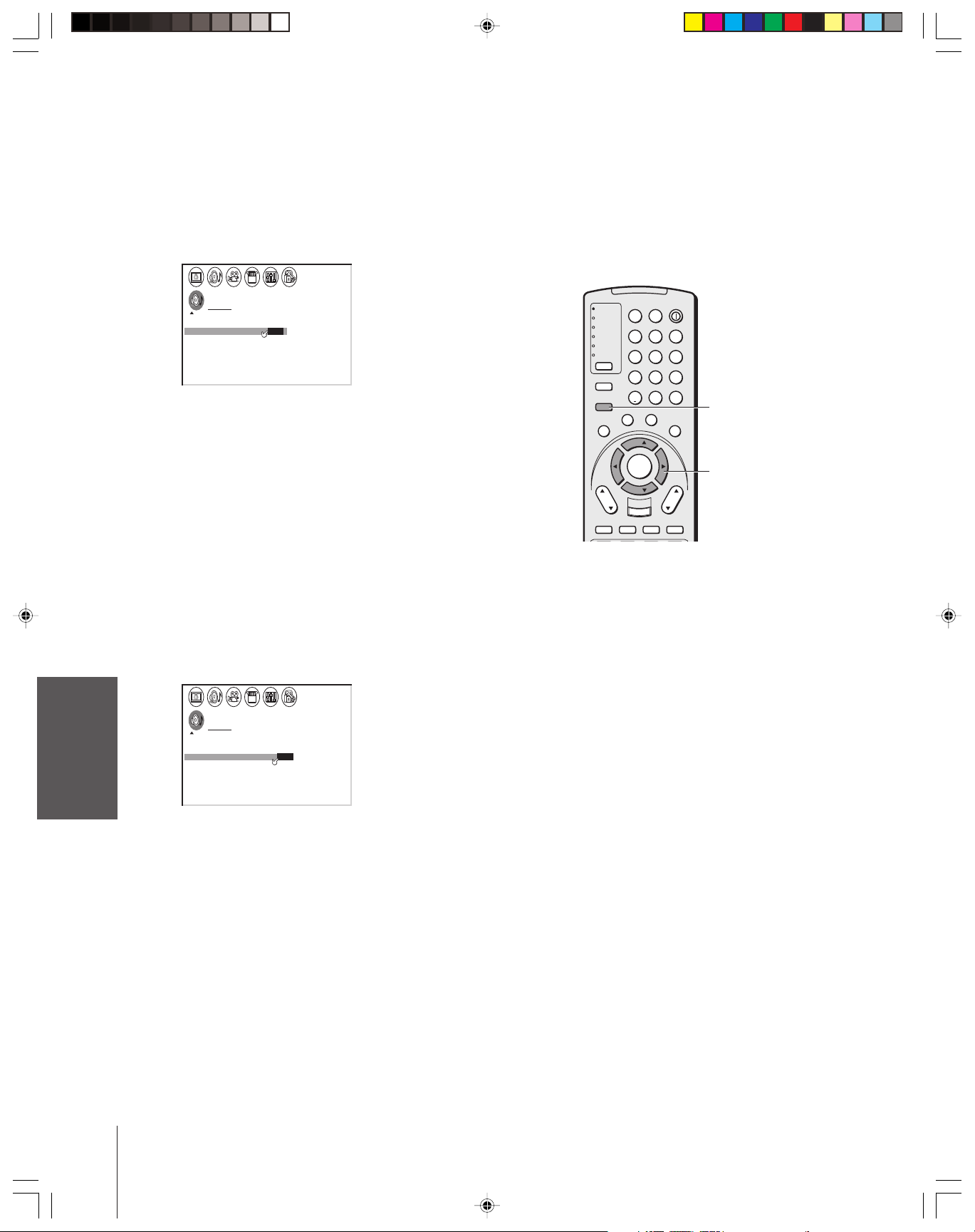
Introduction
Turning off the built-in speakers
Use this feature to turn off the TV speakers when you connect an
audio system (see “Connecting an audio system” on page 14).
To turn off the built-in speakers:
1. Press MENU, then press x or • until AUDIO menu appears.
2. Press y or z to highlight SPEAKERS.
3. Press x or • to highlight OFF.
Note:
Make sure the volume control of your audio
amplifier is set to a moderate listening level.
your TV
Connecting
To turn on the built-in speakers:
Selecting the AUDIO OUT sound
Using the
Remote Control
This feature allows you to select the sound source (MAIN or POP)
that is output from the AUDIO OUT jacks (see “Connecting two
VCRs” on page 12).
This is useful when amplifying or recording the POP sound with
external equipment while hearing the sound of the main picture
through the built-in speakers.
To select the AUDIO OUT sound:
your TV
Setting up
Features
Using the TV’s
AUD OI
CYCLONE
CYC LEVEL
SPEAKERS
AUD O OUTI
STABLE
SOUND
ON
70
ON/ OFF
MA I N
OFF
Highlight ON in step 3 above.
1. Press MENU, and then press x or • until the AUDIO menu
appears.
2. Press y or z to highlight AUDIO OUT.
3. Press x or • to select MAIN or POP.
AUD OI
CYCLONE
CYC LEVEL
SPEAKERS
AUD O OUTI
STABLE
SOUND
ON
70
ON
MAIN /
OFF
PPO
TV
CABLE/SAT
VCR
DVD
AUDIO1
AUDIO2
MODE
PIC SIZE
ACTION
MENU
E
D
I
U
G
P
U
T
E
S
CH
DVD RTN
CH RTN
SLOW/DIR
I
F
N
T
INPUT
POWER
LIGHT SLEEP
123
456
789
+10
100/
0
F
A
V
O
O
R
I
T
E
S
U
B
E
L
T
T
I
T
I
L
E
A
U
D
FAV
ENTER
FAV
VOL
EXIT
DVD CLEAR
RECALL
SKIP/SEARCH
ENT
T
L
I
O
MUTE
MENU
H
E
A
T
E
I
N
R
K
yzx •
Note:
When the POP window is not on the screen,
the sound of the main program is output
through the AUDIO OUT jacks, even if POP
is selected in the AUDIO OUT menu.
Appendix
Index
56
• MAIN : Outputs the sound of the main program through the
AUDIO OUT jacks.
• POP : Outputs the sound of the POP program through the
AUDIO OUT jacks.
Page 57

Using the StableSound® feature
When the signal source is changed, the StableSound® feature limits
the highest volume level to prevent extreme changes in volume (for
example, to prevent the sudden increase in volume that often happens
when a TV program switches to a commercial).
®
To turn on the StableSound
feature:
1. Press MENU, and then press x or • until the AUDIO menu
appears.
2. Press y or z to highlight STABLE SOUND.
3. Press x or • to select ON.
AUD OI
CYCLONE
CYC LEVEL
SPEAKERS
AUD O OUTI
STABLE
SOUND
ON
70
ON
PPO
ON OFF/
To turn off the StableSound feature:
Highlight OFF in step 3 above.
Displaying TV status information on-screen
Press RECALL to display the following information on-screen:
• Antenna mode (when in TV mode)
• Channel number or VIDEO mode selected
•Time (if set)
•Remaining time of ON/SLEEP timers (if set)
• Channel label (if set)
•Stereo or SAP audio status
•V-CHIP rating status
•Image shape
TV
CABLE/SAT
VCR
DVD
AUDIO1
AUDIO2
MODE
PIC SIZE
ACTION
MENU
E
D
I
U
G
P
U
T
E
S
CH
DVD RTN
CH RTN
SLOW/DIR
LIGHT SLEEP
123
456
789
+10
100/
0
F
A
V
O
O
R
F
I
N
I
S
U
B
E
L
T
T
I
T
I
L
T
FAV
ENTER
FAV
EXIT
DVD CLEAR
INPUT
RECALL
SKIP/SEARCH
POWER
Introduction
ENT
T
E
E
A
U
D
I
VOL
MUTE
MENU
T
H
E
A
T
L
E
I
N
R
K
O
yzx •
your TV
Connecting
RECALL
Using the
Remote Control
your TV
Setting up
STEREO
SAP
TV
I
MER
ON T
SLEEP T I MER
LVPG–
11h34m
1h23m
TV L VPG–
I
MER
ON T
SLEEP T I MER
11h34m
1h23m
Features
1
ANT
ABCDNORMAL
CABLECLOCK 9 : 2 5
6
COMPRESS
I
ON
CLOCK
5
ColorStream9:2
DVD
HD1
Using the TV’s
Appendix
Index
57
Page 58

Introduction
Viewing the demo mode
The demo mode automatically demonstrates several of your TV’s
features.
To start the demo:
Press DEMO on the TV front panel.
To stop the demo:
Press DEMO, RECALL, EXIT, or POWER.
Understanding the auto power off feature
your TV
Connecting
The TV will automatically turn itself off after approximately 15
minutes if it is tuned to a vacant channel or a station that completes
its broadcast for the day. This feature does not work in VIDEO mode.
Understanding the last mode memory feature
If the power is cut off while you are viewing the TV, the Last Mode
Memory feature turns the TV on automatically when the power is
resupplied.
If the power is going to be off for a long time and you are going to be
Using the
Remote Control
your TV
Setting up
away from your TV, unplug the power cord to prevent the TV from
turning on in your absence.
Features
Using the TV’s
Appendix
Index
58
Page 59

Appendix
Specifications
Television System
NTSC standard
Channel Coverage
VHF: 2 through 13
UHF: 14 through 69
Cable TV: Mid band (A-8 through A-1, A through I)
Super band (J through W)
Hyper band (AA through ZZ, AAA, BBB)
Ultra band (65 through 94, 100 through 125)
Power Source
120 V AC, 60 Hz
Power Consumption
32HFX73: 172 W (average)
36HF7X3: 174 W (average)
Audio Power
Main: 10 W + 10 W
Sub-woofer: 13 W
Speaker Type
Main: Two 2-3/8 inches (60 × 120 mm)
Sub-woofer: One 4 inches (100 mm) round
Dimensions
32HFX73: Width 34-1/2 inches (875 mm)
Height 26-1/2 inches (673 mm)
Depth 22-5/8 inches (575 mm)
36HFX73: Width 38-3/16 inches (970 mm)
Height 29-9/16 inches (751 mm)
Depth 24-1/4 inches (615 mm)
Mass
32HFX73: 156 lbs (71 kg)
36HFX73: 206 lbs (93 kg)
Supplied Accessories
Remote Control with 2 size “AA” alkaline batteries
Optional Stand
32HFX73: ST3263
36HFX73: ST3663
Design and specifications are subject to change without notice.
Introduction
your TV
Connecting
Using the
Remote Control
Video/Audio Terminals
S-VIDEO INPUT
Y: 1 V(p-p), 75 ohm, negative sync.
C: 0.286 V(p-p) (burst signal), 75 ohm
VIDEO/AUDIO INPUT
VIDEO: 1 V(p-p), 75 ohm, negative sync.
AUDIO: 150 mV(rms) (30% modulation equivalent,
47 k ohm)
ColorStream
Y : 1V(p-p), 75 ohm
P
P
AUDIO: 150 mV(rms), 47 k ohm
VIDEO/AUDIO OUTPUT
VIDEO: 1 V(p-p), 75 ohm, negative sync.
AUDIO: 150 mV(rms) (30% modulation equivalent,
VARIABLE AUDIO OUTPUT
0–300 mV(rms) (30% modulation equivalent, 4.7 k ohm)
AUDIO CENTER CHANNEL INPUT
300 mV(rms) (30% modulation equivalent, 10 k ohm)
DVI/HDCP INPUT
HDCP compliant
E-EDID* 1.3 compliant
DVI-D uncompressed, high-speed, digital single-link
Suggested scan rates: 1080i, 480p, 480i
®
(component video) INPUT
R: 0.7 V(p-p), 75 ohm
B: 0.7 V(p-p), 75 ohm
4.7 k ohm)
connection
your TV
Setting up
Features
Using the TV’s
Appendix
_________
* E-EDID = Enhanced-Extended Display Identification
Index
59
Page 60

Introduction
Troubleshooting
Before calling a service technician, please check the following table for a possible cause of the problem and
some solutions.
Problem Solution
TV will not turn on • Make sure the power cord is plugged in, then press POWER.
• The remote control batteries may be dead. Replace the batteries.
No picture, no sound • Check the antenna/cable connections.
your TV
No sound, picture OK • The sound may be muted. Press VOLUME.
Connecting
Poor picture, sound OK • Check the antenna connections.
Using the
Remote Control
your TV
Setting up
Poor reception of broadcast channels • The station may have broadcast difficulties. Try another channel.
Cannot receive above channel 13 • Make sure the MODE selector on the remote control is set to the mode
Black box appears on the screen • The closed caption feature may be set to one of the Text modes (T1, T2,
Unable to select a certain channel • The channel may be locked with the CH LOCK feature, or erased with
• The station may have broadcast difficulties. Try another channel.
• Make sure the SPEAKERS function in the AUDIO menu is set properly.
• Make sure the AUDIO CENTER CHANNEL switch is set properly.
• If the MTS feature is in SAP mode, change it to STEREO mode.
• The station may have broadcast difficulties. Try another channel.
• Adjust the PICTURE menu.
• Make sure your other devices are connected to the TV correctly.
• Check the antenna connections.
• If you are using a VCR, make sure the TV/VCR button on the remote
control is set correctly.
that corresponds with the signal source type (cable company or outside
antenna).
T3, or T4). Turn closed captioning OFF.
the ADD/ERASE feature.
Features
Using the TV’s
Appendix
Index
60
Multiple images • The station may have broadcast difficulties. Try another channel.
• Antenna reception may be poor. Use a highly directional outdoor
antenna.
Poor color or no color • The station may have broadcast difficulties. Try another channel.
• Adjust the TINT and/or COLOR in the PICTURE menu.
No stereo or SAP sound from a • Make sure the MTS feature is set properly.
known MTS broadcast
The front panel buttons do not operate • Check the FRONT PANEL LOCK feature.
The remote control does not operate • Make sure the appropriate device mode on the remote control is
selected.
• Remove all obstructions between the remote control and the remote
control sensor in the TV.
• The remote control batteries may be dead. Replace the batteries.
Cannot access signal input sources • Check the VIDEO LOCK feature.
(Video1, Video2, Video3,
ColorStream HD1/HD2, DVI/HDCP)
and/or Channels 3 and 4.
Page 61

Limited United States Warranty
for 27'' FST PURE® and All Larger Television Models
Toshiba America Consumer Products, Inc. (“TACP”) and Toshiba
Hawaii, Inc. (“THI”) make the following limited warranties to
original consumers in the United States. THESE LIMITED
WAR RANTIES EXTEND TO THE ORIGINAL CONSUMER
PURCHASER OR ANY PERSON RECEIVING THIS
TELEVISION AS A GIFT FROM THE ORIGINAL CONSUMER
PURCHASER AND TO NO OTHER PURCHASER OR
TRANSFEREE.
PRODUCTS PURCHASED IN THE U.S.A. AND USED IN
CANADA ARE NOT COVERED BY THESE WARRANTIES.
PRODUCTS PURCHASED IN CANADA AND USED IN THE
U.S.A. ARE NOT COVERED BY THESE WARRANTIES.
Limited One (1) Year Warranty on Parts and Labor*
TACP/THI warrant this television and its parts against defects in
materials or workmanship for a period of one (1) year after the
date of original retail purchase. DURING THIS PERIOD, TACP/
THI WILL, AT TACP/THI’S OPTION, REPAIR OR REPLACE A
DEFECTIVE PART WITH A NEW OR REFURBISHED PART
WITHOUT CHARGE TO YOU FOR PARTS OR LABOR. TA CP /
THI Authorized Service Station personnel will come to your home
when warranty service is required. Depending on the type of
repair required, either the service will be performed in your home
or the set will be taken to the TACP/THI Authorized Service
Station for repair and returned to your home at no cost to you.
Limited Two (2) Year Warranty on Picture Tube*
TACP/THI further warrant the picture tube in this television
against defects in materials or workmanship for a period of two
(2) years after the date of original retail purchase. DURING
THIS PERIOD, TACP/THI WILL, AT TACP/THI’S OPTION,
REPAIR OR REPLACE A DEFECTIVE PICTURE TUBE WITH A
NEW OR REFURBISHED PICTURE TUBE WITHOUT
CHARGE TO YOU, EXCEPT THAT, IF A DEFECTIVE PICTURE
TUBE IS REPAIRED OR REPLACED AFTER ONE (1) YEAR
FROM THE DATE OF THE ORIGINAL RETAIL PURCHASE,
YOU PAY LABOR CHARGES INVOLVED IN THE REPAIR OR
REPLACEMENT.
Rental Units
The warranty for rental units begins with the date of first rental or
thirty (30) days from the date of shipment to the rental firm,
whichever comes first.
*Commercial Units
Televisions sold and used for commercial purposes have a limited
ninety (90) day warranty for all parts, labor, and picture tubes.
Owner’s Manual and Product Registration Card
Read this owner’s manual thoroughly before operating this
television. Complete and mail the enclosed product registration
card within ten days after you, or the person who has given you
this product as a gift, purchased this television. Returning the
product registration card will enable TACP/THI to provide you
with better customer service and improved product support.
Failure to return the product registration card will not affect your
rights under this warranty.
Your Responsibility
THE ABOVE WARRANTIES ARE SUBJECT TO THE
FOLLOWING CONDITIONS:
(1) You must provide your bill of sale or other proof of purchase.
(2) All warranty servicing of this television must be made by an
Authorized TACP/THI Service Station.
The warranties from TACP and THI are effective only if the
(3)
television is purchased and operated in the U.S.A. or Puerto Rico.
(4) Labor service charges for set installation, setup, adjustment
of customer controls, and installation or repair of antenna
systems are not covered by these warranties. Reception
problems caused by inadequate antenna systems are your
responsibility.
(5) Warranties extend only to defects in materials or
workmanship as limited above and do not extend to any
television or parts that have been lost or discarded by you or
to damage to television or parts caused by misuse, accident,
Acts of God (such as lightning or fluctuations in electric
power), improper installation, improper maintenance, or use
in violation of instructions furnished by TACP/THI; or to units
that have been modified or had the serial number removed,
altered, defaced, or rendered illegible.
How to Obtain Warranty Services
If, after following all of the operating instructions in this manual
and checking the “Troubleshooting” section, you find that service
is needed:
(1) To find the nearest TACP/THI Authorized Service Station:
For televisions purchased in the United States, except
Hawaii, visit TACP’s web site at www.toshiba.com/tacp,
or call toll free 1-800-631-3811.
For televisions purchased in Hawaii, contact Toshiba Hawaii,
Inc., 327 Kamakee Street, Honolulu, HI 96814, (808) 591-
9281.
(2) Present your bill of sale or other proof of purchase to the
Authorized Service Station. Authorized TACP/THI Service
Station personnel will come to your home when warranty
service is required. Depending on the type of repair required,
either the service will be performed in your home or the set
will be taken to the Authorized Service Station for repair and
returned to your home at no cost to you.
For additional information, visit TACP’s web site:
www.toshiba.com/tacp
ALL WARRANTIES IMPLIED BY THE LAW OF ANY STATE
OF THE U.S.A., INCLUDING THE IMPLIED WARRANTIES OF
MERCHANTABILITY AND FITNESS FOR A PARTICULAR
PURPOSE, ARE EXPRESSLY LIMITED TO THE DURATION
OF THE LIMITED WARRANTIES SET FORTH ABOVE. WITH
THE EXCEPTION OF ANY WARRANTIES IMPLI ED BY THE
LAW OF ANY STATE OF THE U.S.A. AS HEREBY LIMITED,
THE FOREGOING WARRANTY IS EXCLUSIVE AND IN LIEU
OF ALL OTHER WARRANTIES, GUARANTEES,
AGREEMENTS, AN D SIMILAR OBLIGATIONS OF TACP OR
THI WITH RESPECT TO THE REPAIR OR REPLACEMENT OF
ANY PARTS. IN NO EVENT SHALL TACP OR THI BE LIABLE
FOR CONSEQUENTIAL OR INCIDENTAL DAMAGES.
No person, agent, distributor, dealer, or company is authorized to
change, modify, or extend the terms of these warranties in any
manner whatsoever. The time within which action must be
commenced to enforce any obligation of TACP or THI arising
under this warranty or under any law of the United States or of
any state thereof is hereby limited to 90 days from the date you
discover, or should have discovered, the defect. This limitation
does not apply to implied warranties arising under the law of any
state of the U.S.A.
THIS WARRANTY GIVES YOU SPECIFIC LEGAL RIGHTS,
AND YOU MAY ALSO HAVE OTHER RIGHTS, WHICH MAY
VARY FROM STATE TO STATE IN THE U.S.A. SOME STATES
OF THE U.S.A. DO NOT ALLOW LIMITATIONS ON THE
DURATION OF AN IMPLIED WARRANTY, LIMITATIONS ON
THE TIME WITHIN WHICH AN ACTION MAY BE BROUGHT,
OR THE EXCLUSION OR LIMITATION OF INCIDENTAL OR
CONSEQUENTIAL DAMAGES; THEREFORE, THE ABOVE
LIMITATIONS OR EXCLUSIONS MAY NOT APPLY TO YOU
UNDER SUCH CIRCUMSTANCES.
FST PURE® is a registered trademark of Toshiba America Consumer Products, Inc.
.
REV. MAR02
61
Introduction
your TV
Connecting
Using the
Remote Control
your TV
Setting up
Features
Using the TV’s
Appendix
Index
Page 62

Limited Canada Warranty
for 27'' FST PURE® and All Larger Television Models
Introduction
your TV
Connecting
Using the
Remote Control
your TV
Setting up
Features
Using the TV’s
Appendix
Toshiba of Canada Limited (“TCL”) makes the following limited
warranties to original consumers in Canada.
THESE LIMITED WARRANTIES EXTEND TO THE ORIGINAL
CONSUMER PURCHASER OR ANY PERSON RECEIVING
THIS TELEVISION AS A GIFT FROM THE ORIGINAL
CONSUMER PURCHASER AND TO NO OTHER
PURCHASER OR TRANSFEREE.
PRODUCTS PURCHASED IN THE U.S.A. AND USED IN
CANADA ARE NOT COVERED BY THESE WARRANTIES.
PRODUCTS PURCHASED IN CANADA AND USED IN THE
U.S.A. ARE NOT COVERED BY THESE WARRANTIES.
Limited One (1) Year Warranty on Parts and Labor*
TCL warrants this television and its parts against defects in
materials or workmanship for a period of one (1) year after the
date of original retail purchase. DURING THIS PERIOD, TCL
WILL, AT TCL’S OPTION, REPAIR OR REPLACE A DEFECTIVE
PART WITH A NEW OR REFURBISHED PART WITHOUT
CHARGE TO YOU FOR PARTS OR LABOR. TCL Authorized
Service Depot personnel will come to your home when warranty
service is required. Depending on the type of repair required,
either the service will be performed in your home or the set will
be taken to the TCL Authorized Service Depot for repair and
returned to your home at no cost to you. IN-HOME SERVICE
ONLY APPLIES WITHIN 100 KILOMETERS OF AN
AUTHORIZED TCL SERVICE DEPOT.
Limited Two (2) Year Warranty on Picture Tube*
TCL further warrants the picture tube in this television against
defects in materials or workmanship for a period of two (2) years
after the date of original retail purchase. DURING THIS
PERIOD, TCL WILL, AT TCL’S OPTION, REPAIR OR REPLACE
A DEFECTIVE PICTURE TUBE WITH A NEW OR
REFURBISHED PICTURE TUBE WITHOUT CHARGE TO YOU,
EXCEPT THAT, IF A DEFECTIVE PICTURE TUBE IS REPAIRED
OR REPLACED AFTER ONE (1) YEAR FROM THE DATE OF
THE ORIGINAL RETAIL PURCHASE, YOU PAY LABOR
CHARGES INVOLVED IN THE REPAIR OR REPLACEMENT.
Rental Units
The warranty for rental units begins with the date of first rental or
thirty (30) days from the date of shipment to the rental firm,
whichever comes first.
*Commercial Units
Televisions sold and used for commercial purposes have a limited
ninety (90) day warranty for all parts, labor, and picture tubes.
Owner’s Manual
Read this owner’s manual thoroughly before operating this
television.
Your Responsibility
THE ABOVE WARRANTIES ARE SUBJECT TO THE
FOLLOWING CONDITIONS:
(1) You must provide your bill of sale or other proof of purchase.
(2) All warranty servicing of this television must be made by an
(3) The warranties from TCL are effective only if the television is
(4) Labor service charges for set installation, setup, adjustment
Index
Authorized TCL Service Depot.
purchased in Canada from an authorized TCL dealer and
operated in Canada.
of customer controls, and installation or repair of antenna
systems are not covered by these warranties. Reception
problems caused by inadequate antenna systems are your
responsibility.
(5) Warranties extend only to defects in materials or
workmanship as limited above and do not extend to any
television or parts that have been lost or discarded by you or
to damage to television or parts caused by misuse, accident,
Acts of God (such as lightning or fluctuations in electric
power), improper installation, improper maintenance, or use
in violation of instructions furnished by TCL; or to units that
have been modified or had the serial number removed,
altered, defaced, or rendered illegible.
How to Obtain Warranty Services
If, after following all of the operating instructions in this manual
and checking the “Troubleshooting” section, you find that service
is needed:
(1) To find the nearest TCL Authorized Service Depot, visit TCL’s
web site: www.toshiba.ca.
(2) Present your bill of sale or other proof of purchase to the
Authorized Service Depot. Authorized TCL Service Depot
personnel will come to your home when warranty service is
required. Depending on the type of repair required, either
the service will be performed in your home or the set will be
taken to the Authorized Service Depot for repair and
returned to your home at no cost to you. IN-HOME
SERVICE ONLY APPLIES WITHIN 100 KILOMETERS OF
AN AUTHORIZED TCL SERVICE DEPOT.
For additional information, visit TCL’s web site:
ALL WARRANTIES IMPLIED BY THE LAW OF ANY
PROVINCE OF CANADA, INCLUDING THE IMPLIED
WAR RANTIES OF MERCHANTABILITY AND FITNESS FOR
A PARTICULAR PURPOSE, ARE EXPRESSLY LIMITED TO
THE DURATION OF THE LIMITED WARRANTIES SET FORTH
ABOVE. WITH THE EXCEPTION OF ANY WARRANTIES
IMPLIED BY THE LAW OF ANY PROVINCE OF CANADA AS
HEREBY LIMITED, THE FOREGOING WARRANTY IS
EXCLUSIVE AND IN LIEU OF ALL OTHER WARRANTIES,
GUARANTEES, AGREEMENTS, AND SIMILAR
OBLIGATIONS OF TCL WITH RESPECT TO THE REPAIR OR
REPLACEMENT OF ANY PARTS. IN NO EVENT SHALL TCL
BE LIABLE FOR CONSEQUENTIAL OR INCIDENTAL
DAMAGE S.
No person, agent, distributor, dealer, or company is authorized to
change, modify, or extend the terms of these warranties in any
manner whatsoever. The time within which action must be
commenced to enforce any obligation of TCL arising under this
warranty or under any law of Canada or of any province thereof,
is hereby limited to 90 days from the date you discover, or should
have discovered, the defect. This limitation does not apply to
implied warranties arising under the law of any province of
Canada.
THIS WARRANTY GIVES YOU SPECIFIC LEGAL RIGHTS,
AND YOU MAY ALSO HAVE OTHER RIGHTS, WHICH MAY
VARY FROM PROVINCE TO PROVINCE IN CANADA. SOME
PROVINCES OF CANADA DO NOT ALLOW LIMITATIONS
ON THE DURATION OF AN IMPLI ED WARRANTY,
LIMITATIONS ON THE TIME WITHIN WHICH AN ACTION
MAY BE BROUGHT, OR THE EXCLUSION OR LIMITATION
OF INCIDENTAL OR CONSEQUENTIAL DAMAGES;
THEREFORE, THE ABOVE LIMITATIONS OR EXCLUSIONS
MAY NOT APPLY TO YOU UNDER SUCH
CIRCUMSTANCES.
FST PURE® is a registered trademark of Toshiba America Consumer Products, Inc.
www.toshiba.ca
REV. MAR02
62
Page 63

Index
A
A/V cables (standard) ......................................................... 7
A/V receiver connection ................................................... 14
ANT 1/2 ...................................................................................25
Antenna cables (coaxial) ................................................... 7
AUDIO OUT sound, selecting ....................................... 56
Audio system connection ................................................. 14
Auto aspect ............................................................................ 33
Auto favorite .......................................................................... 37
Auto power off ...................................................................... 58
B
BACKGROUND selection ................................................51
Back of the TV ........................................................................ 6
C
CableClear™ DNR ...............................................................45
Cable converter box connection ..................................... 8
Camcorder connection ...................................................... 12
CH yz buttons .................................................................... 27
CH LABELING ......................................................................30
CH LOCK.................................................................................41
CH RTN button .....................................................................28
Channel Number buttons ................................................ 27
Channel programming
ADD/ERASE ..................................................................... 26
Automatic programming ............................................. 25
TV/CABLE selection ......................................................26
Cinema mode ........................................................................33
Clock, setting ........................................................................51
Closed caption ...................................................................... 49
Color temperature ...............................................................46
ColorStream (component) cables ................................... 7
CYCLONE ...............................................................................55
D
DEMO button........................................................................58
Display format....................................................................... 47
Dolby virtual .......................................................................... 53
Double-window (“POP”) feature ...................................34
DTV receiver connection .................................................. 11
DVD connection .............................................................. 9, 10
DVI cable .................................................................................. 7
DVI/HDCP connection ...................................................... 13
F G
FAV yz buttons ..................................................................29
FAVORITE button ................................................................. 37
Favorite channels, programming................................... 28
FOCUS feature .................................................................... 54
Front of the TV ........................................................................ 6
Front panel lock ...................................................................43
Game timer ............................................................................43
I
Image shape selection ......................................................31
L M
Labeling channels ...............................................................30
Labeling video inputs ........................................................48
Language selection ............................................................24
Last mode memory .............................................................58
Locking channels ................................................................41
Locking video inputs .......................................................... 42
Locks menu ...........................................................................38
Menu system ......................................................................... 23
MTS feature ........................................................................... 52
MUTE button ......................................................................... 52
O P
ON-timer .................................................................................50
Picture adjustments
COLOR TEMPERATURE ..............................................46
FLESH TONE ....................................................................45
Picture mode ....................................................................44
Picture quality ..................................................................44
Picture-out-picture (POP)
CH SCAN button ........................................................... 36
FREEZE button ................................................................ 35
POP CH yz buttons .................................................... 34
POP DIRECT CH button ...............................................34
SOURCE button ............................................................. 34
SPLIT button .................................................................... 34
SWAP button .................................................................... 35
POP (also see “Picture-out-picture”) ..........................34
Q R
Quick connect guide .......................................................... 24
RECALL button ....................................................................57
Remote control
Battery installation .........................................................15
Learning about the buttons ........................................ 22
Programming .................................................................... 18
RESET .............................................................................. 46, 55
S
SAP sound ..............................................................................52
Satellite receiver connection............................................. 9
Set-top box ............................................................................11
Size of Double-Window, adjusting ............................... 35
Sleep timer .............................................................................50
Sound quality adjustments ..............................................54
SPEAKERS on/off ...............................................................56
Specifications ........................................................................ 59
SpeedSurf mode ..................................................................27
SRS 3D surround.................................................................54
StableSound
Stereo sound .........................................................................52
SurfLock™............................................................................... 28
S-video cables ........................................................................ 7
SVM .......................................................................................... 47
®
........................................................................ 57
T
Tilt correction ........................................................................ 27
Troubleshooting .................................................................. 60
TruBass feature ....................................................................54
TV/VIDEO button ......................................................... 25, 48
V
V-CHI P
BLOCKING OPTION ......................................................40
ENABLE BLOCKING .................................................... 39
MPAA RATING ................................................................ 40
NEW PIN CODE ..............................................................43
TV RATING ........................................................................39
Unlocking programs temporarily..............................41
VCR connection ..................................................................... 7
VIDEO LABEL ...................................................................... 48
VIDEO LOCK .........................................................................42
W
Warranty .......................................................................... 61, 62
WOW surround sound feature ....................................... 54
63
Introduction
your TV
Connecting
Using the
Remote Control
your TV
Setting up
Features
Using the TV’s
Appendix
Index
Page 64

HEAD OFFICE: 82 TOTOWA ROAD, WAYNE, NJ 07470, U.S.A.
NATIONAL SERVICE DIVISION:1420-B TOSHIBA DRIVE, LEBANON, TN 37087, U.S.A.
HEAD OFFICE: 327 KAMAKEE STREET, HONOLULU, HI 96814, U.S.A. – TEL: (808) 591-9281
HEAD OFFICE: 191 McNABB STREET, MARKHAM, ONTARIO, L3R 8H2, CANADA – TEL: (905) 470-5400
SERVICE CENTERS:
TORONTO: 191 McNABB STREET, MARKHAM, ONTARIO L3R 8H2, CANADA – TEL: (905) 470- 5400
MONTREAL: 1643 NORTH SERVICE RD., TRANS-CANADA HIGHWAY, DORVAL QUEBEC, H9P 1J1, CANADA – TEL: (514) 856-4100
VANCOUVER: 22171 FRASERWOOD WAY, RICHMOND, B.C., V6W 1J5, CANADA – TEL: (604) 303-2500
MANUFACTURED BY
CYCLONE is a registered trademark of Toshiba Corporation.
ColorStream and StableSound are registered trademarks of Toshiba America Consumer Products, Inc.
CableClear and SurfLock are trademarks of Toshiba America Consumer Products, Inc.
PRINTED IN USA
(03-07) B
 Loading...