


 Loading...
SERVICE MANUAL
MULTIFUNCTIONAL DIGITAL SYSTEMS
e-STUDIO350/450 e-STUDIO352/452 e-STUDIO353/453
Model: DP-3520/3540/4520/4540
Publish Date: November 2003
File No. SME030028I0
R03092140702-TTEC
Ver09_2008-04

Trademarks
•The official name of Windows 95 is Microsoft Windows 95 Operating System.
•The official name of Windows 98 is Microsoft Windows 98 Operating System.
•The official name of Windows Me is Microsoft Windows Millennium Edition Operating System.
•The official name of Windows 2000 is Microsoft Windows 2000 Operating System.
•The official name of Windows XP is Microsoft Windows XP Operating System.
•Microsoft, Windows, Windows NT and the brand names and product names of other Microsoft products are trademarks or registered trademarks of Microsoft Corporation in the U.S. and/or other countries.
•Apple, AppleTalk, Macintosh, and Mac are trademarks of Apple Computer, Inc. in the U.S. and other countries.
•PostScript is a trademark of Adobe Systems Incorporated.
•NOVELL, NetWare, and NDS are trademarks or registered trademarks of Novell, Inc.
•Molykote is a registered trademark of Dow Corning Corporation.
•iCLASS is a trademark of HID Corporation.
•MIFARE is a trademark of Royal Philips Electronics.
•Other company names and product names in this manual are the trademarks of their respective companies.
©2003 - 2008 TOSHIBA TEC CORPORATION All rights reserved
Under the copyright laws, this manual cannot be reproduced in any form without prior written permission of TOSHIBA TEC CORPORATION. No patent liability is assumed, however, with respect to the use of the information contained herein.
08/04
GENERAL PRECAUTIONS REGARDING THE INSTALLATION AND SERVICE FOR e-STUDIO350/352/353/450/452/453
The installation and service should be done by a qualified service technician.
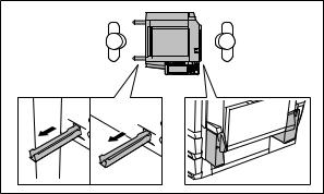
1.Transportation / Installation
•When transporting/installing the equipment, employ two persons and be sure to use the positions as indicated below.
The equipment is quite heavy and weighs approximately 83kg (182.98 lb.): e-STUDIO350/450 / 86kg (189.59 lb): e-STUDIO352/353/452/453 therefore pay full attention when handling it.
•Be sure not to hold the movable parts or units (e.g. the control panel, ADU or RADF) when transporting the equipment.
•Be sure to use a dedicated outlet with AC 110V/13.2A, 115V or 127V / 12A, 220-240V or 240V / 8A for its power source.
•The equipment must be grounded for safety. Never ground it to a gas pipe or a water pipe.
•Select a suitable place for installation.
Avoid excessive heat, high humidity, dust, vibration and direct sunlight.
•Also provide proper ventilation as the equipment emits a slight amount of ozone.
•To insure adequate working space for the copying operation, keep a minimum clearance of 80 cm (32”) on the left, 80 cm (32”) on the right and 10 cm (4”) in the rear.
•The socket-outlet shall be installed near the equipment and shall be easily accessible.
•Be sure to fix and plug in the power cable securely after the installation so that no one trips over it.
2.Service of Machines
•Basically, be sure to turn the main switch off and unplug the power cord during service.
•Be sure not to touch high-temperature sections such as the exposure lamp, the fuser unit, the damp heater and their periphery.
•Be sure not to touch high-voltage sections such as the chargers, developer, IH control circuit, high-voltage transformer, exposure lamp control inverter, inverter for the LCD backlight and power supply unit. Especially, the board of these components should not be touched since the electric charge may remain in the capacitors, etc. on them even after the power is turned OFF.
•Be sure not to touch rotating/operating sections such as gears, belts, pulleys, fan, etc.
•Be careful when removing the covers since there might be the parts with very sharp edges underneath.
•When servicing the machines with the power turned ON, be sure not to touch live sections and rotating/operating sections. Avoid exposure to laser radiation.
07/11

•Use suitable measuring instruments and tools.
•Avoid exposure to laser radiation during servicing.
-Avoid direct exposure to the beam.
-Do not insert tools, parts, etc. that are reflective into the path of the laser beam.
-Remove all watches, rings, bracelets, etc. that are reflective.
•Unplug the power cable and clean the area around the prongs of the plug once a year or more.
A fire may occur when dust lies on this area.
3.Main Service Parts for Safety
•The breaker, door switch, fuse, thermostat, thermofuse, thermistor, etc. are particularly important for safety. Be sure to handle/install them properly. If these parts are shorted circuit and/or made their functions out, they may burn down, for instance, and may result in fatal accidents. Do not allow a short circuit to occur. Do not use the parts not recommended by Toshiba TEC Corporation.
4.Cautionary Labels
•During servicing, be sure to check the rating plate and the cautionary labels such as “Unplug the power cord during service”, “Hot area”, “Laser warning label” etc. to see if there is any dirt on their surface and whether they are properly stuck to the equipment.
5.Disposition of Consumable Parts, Packing Materials, Used batteries and RAM-ICs
•Regarding the recovery and disposal of the equipment, supplies, consumable parts, packing materials, used batteries and RAM-ICs including lithium batteries, follow the relevant local regulations or rules.
6.Reassembly of disassembled parts is the reverse of the disassembly unless otherwise noted in this manual or other related documents.
Care should be taken that small parts, such as screws, washers, pins, E-rings, star washers, harnesses are not installed in the wrong places.
7.Basically, the machine should not be operated with any parts removed or disassembled.
8.Precautions Against Static Electricity
•The PC board must be stored in an anti-electrostatic bag and handled carefully using a wristband, because the ICs on it may become damaged due to static electricity.
Caution: Before using the wristband, pull out the power cord plug of the equipment and make sure that there are no uninsulated charged objects in the vicinity.
Caution : Dispose of used batteries and RAM-ICs including lithium batteries according to this manual.
Attention : Se débarrasser de batteries et RAM-ICs usés y compris les batteries en lithium selon ce manuel.
Vorsicht : Entsorgung der gebrauchten Batterien und RAM-ICs (inklusive der LithiumBatterie) nach diesem Handbuch.
07/06
CONTENTS
1. SPECIFICATIONS / ACCESSORIES / OPTIONS / SUPPLIES..................................... |
1-1 |
||
1.1 |
Specifications........................................................................................................................ |
1-1 |
|
1.2 |
Accessories.......................................................................................................................... |
1-5 |
|
1.3 |
Options................................................................................................................................. |
1-6 |
|
|
1.3.1 |
e-STUDIO350/450..................................................................................................... |
1-6 |
|
1.3.2 |
e-STUDIO352/452..................................................................................................... |
1-7 |
1.4 |
Supplies................................................................................................................................ |
1-8 |
|
1.5 |
System List........................................................................................................................... |
1-9 |
|
|
1.5.1 |
e-STUDIO350/450..................................................................................................... |
1-9 |
|
1.5.2 |
e-STUDIO352/452................................................................................................... |
1-10 |
2. OUTLINE OF THE MACHINE........................................................................................ |
2-1 |
||
2.1 |
Sectional View...................................................................................................................... |
2-1 |
|
2.2 |
Electric Parts Layout............................................................................................................. |
2-5 |
|
2.3 |
Symbols and Functions of Various Components................................................................ |
2-15 |
|
2.4 |
General Description............................................................................................................ |
2-22 |
|
|
2.4.1 |
System block diagram............................................................................................. |
2-22 |
|
2.4.2 |
Construction of boards............................................................................................ |
2-24 |
2.5 |
Installation and Replacement of Covers and PC boards.................................................... |
2-26 |
|
|
2.5.1 |
External covers........................................................................................................ |
2-26 |
|
2.5.2 |
PC boards................................................................................................................ |
2-32 |
2.6 |
Options............................................................................................................................... |
2-40 |
|
3. COPY PROCESS........................................................................................................... |
3-1 |
|
3.1 |
General Description of Copying Process.............................................................................. |
3-1 |
3.2 |
Details of Copying Process................................................................................................... |
3-2 |
3.3 |
Comparison with DP4500/3500.......................................................................................... |
3-10 |
4. GENERAL OPERATION................................................................................................ |
4-1 |
||
4.1 |
Overview of Operation.......................................................................................................... |
4-1 |
|
4.2 |
Description of Operation....................................................................................................... |
4-1 |
|
|
4.2.1 |
Warming-up............................................................................................................... |
4-1 |
|
4.2.2 Ready state (ready for copying)................................................................................ |
4-2 |
|
|
4.2.3 Drawer feed copying (Upper drawer paper feeding)................................................. |
4-2 |
|
|
4.2.4 |
Bypass feed copying................................................................................................. |
4-5 |
|
4.2.5 |
Interruption copying................................................................................................... |
4-5 |
4.3 |
Detection of Abnormality....................................................................................................... |
4-6 |
|
|
4.3.1 |
Types of abnormality................................................................................................. |
4-6 |
|
4.3.2 |
Description of abnormality......................................................................................... |
4-7 |
© 2003 - 2008 TOSHIBA TEC CORPORATION All rights reserved |
|
e-STUDIO350/352/353/450/452/453 |
|
05/11 |
CONTENTS |
|
|
|
4.4 |
Flow Chart.......................................................................................................................... |
4-12 |
|
|
|
4.4.1 Immediately after the power is turned ON............................................................... |
4-12 |
|
|
|
4.4.2 Automatic paper feed copying................................................................................. |
4-14 |
|
5. |
CONTROL PANEL......................................................................................................... |
5-1 |
||
|
5.1 |
Control Panel and Display Panel.......................................................................................... |
5-1 |
|
|
5.2 |
Items Shown on the Display Panel....................................................................................... |
5-2 |
|
|
|
5.2.1 |
Display ...................................................................................................................... |
5-3 |
|
5.3 |
Relation between the Equipment State and Operator’s Operation....................................... |
5-8 |
|
|
5.4 |
Description of Operation....................................................................................................... |
5-9 |
|
|
|
5.4.1 Dot matrix LCD circuit................................................................................................ |
5-9 |
|
|
|
5.4.2 |
LED display circuit................................................................................................... |
5-11 |
|
5.5 |
Disassembly and Replacement.......................................................................................... |
5-12 |
|
6. |
SCANNER...................................................................................................................... |
6-1 |
||
|
6.1 |
Function................................................................................................................................ |
6-1 |
|
|
6.2 |
Construction.......................................................................................................................... |
6-2 |
|
|
6.3 |
Description of Operation....................................................................................................... |
6-4 |
|
|
|
6.3.1 |
Scan motor................................................................................................................ |
6-4 |
|
|
6.3.2 |
Scanning drive circuit ............................................................................................... |
6-5 |
|
|
6.3.3 |
Initialization at power-ON ......................................................................................... |
6-7 |
|
6.4 |
Control of Exposure Lamp.................................................................................................... |
6-8 |
|
|
|
6.4.1 |
General description................................................................................................... |
6-8 |
|
|
6.4.2 |
Exposure lamp........................................................................................................... |
6-9 |
|
|
6.4.3 Control circuit for the exposure lamp....................................................................... |
6-10 |
|
|
6.5 |
General Description of CCD Control................................................................................... |
6-11 |
|
|
|
6.5.1 |
Opto-electronic conversion...................................................................................... |
6-11 |
|
|
6.5.2 |
Shading correction................................................................................................... |
6-11 |
|
6.6 |
Automatic Original Size Detection Circuit........................................................................... |
6-12 |
|
|
|
6.6.1 Principle of original size detection........................................................................... |
6-12 |
|
|
|
6.6.2 Process of detection of original size........................................................................ |
6-12 |
|
|
6.7 |
Disassembly and Replacement.......................................................................................... |
6-16 |
|
7. |
IMAGE PROCESSING................................................................................................... |
7-1 |
||
|
7.1 |
General Description.............................................................................................................. |
7-1 |
|
|
7.2 |
Configuration........................................................................................................................ |
7-3 |
|
|
7.3 |
SLG Board............................................................................................................................ |
7-4 |
|
|
|
7.3.1 |
Features.................................................................................................................... |
7-4 |
|
|
7.3.2 Functions of image processing circuit....................................................................... |
7-5 |
|
|
7.4 |
LGC Board............................................................................................................................ |
7-9 |
|
|
|
7.4.1 |
Features.................................................................................................................... |
7-9 |
|
|
7.4.2 Functions of image processing circuit....................................................................... |
7-9 |
|
|
7.5 |
Laser Driving PC Board (LDR board)................................................................................. |
7-10 |
|
e-STUDIO350/352/353/450/452/453 |
ii © 2003 - 2008 TOSHIBA TEC CORPORATION All rights reserved |
CONTENTS |
|
8. LASER OPTICAL UNIT................................................................................................. |
8-1 |
|
8.1 |
General Description.............................................................................................................. |
8-1 |
8.2 |
Structure............................................................................................................................... |
8-3 |
8.3 |
Laser Diode.......................................................................................................................... |
8-7 |
8.4 |
Laser Optical Unit Cooling Fan............................................................................................. |
8-8 |
8.5 |
Polygonal Motor.................................................................................................................... |
8-8 |
8.6 |
Disassembly and Replacement............................................................................................ |
8-9 |
9. PAPER FEEDING SYSTEM........................................................................................... |
9-1 |
||
9.1 |
Functions.............................................................................................................................. |
9-1 |
|
9.2 |
Operation.............................................................................................................................. |
9-5 |
|
|
9.2.1 Operation of bypass pickup roller.............................................................................. |
9-5 |
|
|
9.2.2 Operation of drawer pickup roller.............................................................................. |
9-5 |
|
|
9.2.3 |
Separation of paper................................................................................................... |
9-6 |
|
9.2.4 |
General operation...................................................................................................... |
9-7 |
9.3 |
Drive Circuit of Tray-up Motor............................................................................................... |
9-9 |
|
9.4 |
Disassembly and Replacement.......................................................................................... |
9-10 |
|
10. DRIVE SYSTEM........................................................................................................... |
10-1 |
|
10.1 |
General Description............................................................................................................ |
10-1 |
10.2 |
Functions............................................................................................................................ |
10-1 |
10.3 |
Main Motor.......................................................................................................................... |
10-2 |
|
10.3.1 Main motor drive...................................................................................................... |
10-2 |
|
10.3.2 Control signals......................................................................................................... |
10-3 |
10.4 |
Disassembly and Replacement.......................................................................................... |
10-4 |
11. DRUM RELATED SECTION........................................................................................ |
11-1 |
|
11.1 |
Configuration...................................................................................................................... |
11-1 |
11.2 |
Functions............................................................................................................................ |
11-2 |
11.3 |
Output Control Circuits of High-Voltage Transformer......................................................... |
11-5 |
|
11.3.1 Overview.................................................................................................................. |
11-5 |
|
11.3.2 Description of operations......................................................................................... |
11-5 |
11.4 |
Drum Temperature Detection Circuit................................................................................... |
11-7 |
11.5 |
Temperature/Humidity Sensor............................................................................................ |
11-8 |
|
11.5.1 General description................................................................................................. |
11-8 |
|
11.5.2 Construction............................................................................................................ |
11-8 |
11.6 |
Disassembly and Replacement.......................................................................................... |
11-9 |
12. DEVELOPMENT SYSTEM.......................................................................................... |
12-1 |
|
12.1 |
Configuration...................................................................................................................... |
12-1 |
12.2 |
Functions............................................................................................................................ |
12-2 |
12.3 |
Drive Circuit of Toner Motor .............................................................................................. |
12-3 |
© 2003 - 2008 TOSHIBA TEC CORPORATION All rights reserved iii |
e-STUDIO350/352/353/450/452/453 |
|
CONTENTS |
12.4 |
Auto-Toner Circuit............................................................................................................... |
12-4 |
|
12.4.1 General description................................................................................................. |
12-4 |
|
12.4.2 Function of auto-toner sensor.................................................................................. |
12-5 |
|
12.4.3 Adjustment using the temperature / humidity sensor.............................................. |
12-7 |
|
12.4.4 Adjustment using the drum thermistor..................................................................... |
12-7 |
12.5 |
Disassembly and Replacement.......................................................................................... |
12-8 |
13. FUSER UNIT / PAPER EXIT SECTION....................................................................... |
13-1 |
|
13.1 |
General Description............................................................................................................ |
13-1 |
13.2 |
Operation............................................................................................................................ |
13-1 |
13.3 |
Functions............................................................................................................................ |
13-2 |
13.4 |
Heater Control Circuit......................................................................................................... |
13-4 |
|
13.4.1 Configuration........................................................................................................... |
13-4 |
|
13.4.2 Heating principle of IH Heater................................................................................. |
13-5 |
|
13.4.3 IH control circuit interface........................................................................................ |
13-6 |
|
13.4.4 Relation between system configuration and IH output............................................ |
13-7 |
|
13.4.5 Temperature detection section................................................................................ |
13-8 |
|
13.4.6 Abnormality in the IH control circuit....................................................................... |
13-13 |
13.5 |
Control Circuit of Exit Motor ............................................................................................. |
13-15 |
13.6 |
Exit Motor Drive ............................................................................................................... |
13-15 |
13.7 |
Disassembly and Replacement........................................................................................ |
13-16 |
14. AUTOMATIC DUPLEXING UNIT (ADU) |
......................................................................14-1 |
|
14.1 |
General Description............................................................................................................ |
14-1 |
14.2 |
Description of Operations................................................................................................... |
14-2 |
14.3 |
Drive of ADU....................................................................................................................... |
14-8 |
14.4 |
Flow Chart.......................................................................................................................... |
14-9 |
14.5 |
Disassembly and Replacement........................................................................................ |
14-11 |
15. |
POWER SUPPLY UNIT................................................................................................ |
15-1 |
|
|
15.1 |
Construction........................................................................................................................ |
15-1 |
|
15.2 |
Operation of DC Output Circuits......................................................................................... |
15-1 |
|
15.3 |
Output Channel................................................................................................................... |
15-2 |
|
15.4 |
Fuse.................................................................................................................................... |
15-4 |
|
15.5 |
Configuration of Power Supply Unit.................................................................................... |
15-5 |
|
15.6 |
Sequence of Power Supply ............................................................................................... |
15-6 |
|
15.7 |
AC Wire Harness ............................................................................................................... |
15-7 |
16. |
PC BOARDS................................................................................................................ |
16-1 |
|
e-STUDIO350/352/353/450/452/453 |
iv © 2003 - 2008 TOSHIBA TEC CORPORATION All rights reserved |
CONTENTS |
|

1. SPECIFICATIONS / ACCESSORIES / OPTIONS / SUPPLIES |
|
1 |
|
|
|
1.1 Specifications
Values in [ ] are for e-STUDIO450/452/453 in case that the specification is different between e-STUDIO350/352/353 and e-STUDIO450/452/453.
• Copy process |
Indirect electrophotographic process (dry) |
|
|
|
|
|||||||||
• Type |
Desktop type (console type: when paper feed pedestal (PFP) and large ca- |
|||||||||||||
|
|
|
pacity feeder (LCF) are installed) |
|
|
|
|
|||||||
• Original table |
Fixed type (the left rear corner used as guide to place originals) |
|||||||||||||
• Accepted originals |
Sheet, book and 3-dimensional object. The reversing automatic document |
|||||||||||||
|
|
|
feeder (RADF) only accepts paper which are not pasted or stapled. Carbon |
|||||||||||
|
|
|
paper are not acceptable either. |
|
|
|
|
|||||||
|
|
|
Maximum size : A3/LD |
|
|
|
|
|
|
|
|
|||
|
|
|
|
|
|
|
Single-sided originals |
Double-sided originals |
|
|||||
|
|
|
|
|
MR-3015 |
|
|
50 to 127 g/m2 |
|
50 to 105 g/m2 |
|
|||
|
|
|
|
|
|
(13 lb. Bond to 34 lb. Bond) |
(13 lb. Bond to 28 lb. Bond) |
|
||||||
|
|
|
|
|
MR-3018 |
|
|
35 to 157 g/m2 |
|
50 to 157 g/m2 |
|
|||
|
|
|
|
|
|
(9.3 lb. Bond to 58 lb. Cover) |
(13 lb. Bond to 58 lb. Cover) |
|
||||||
• Copy speed (Copies/min.) |
|
|
|
|
|
|
|
|
|
|
|
|||
e-STUDIO350/352/353 |
|
|
|
|
|
|
|
|
|
|
|
|||
Paper size |
|
Drawer |
|
Bypass feed |
|
PFP |
|
LCF |
|
|||||
Paper size |
|
|
Size specified |
|
Size not specified |
|
|
|
|
|||||
|
|
|
|
|
|
|
|
|||||||
A4, LT, B5 |
|
|
35 |
35 |
|
|
18 |
|
|
35 |
|
35 |
|
|
A4-R, B5-R, |
|
|
25 |
25 |
|
|
18 |
|
|
25 |
|
– |
|
|
A5-R, LT-R, ST-R |
|
|
|
|
|
|
|
|
||||||
|
|
|
|
|
|
|
|
|
|
|
|
|
||
B4, LG |
|
|
21 |
21 |
|
|
18 |
|
|
21 |
|
– |
|
|
A3, LD |
|
|
18 |
18 |
|
|
18 |
|
|
18 |
|
– |
|
|
e-STUDIO450/452/453 |
|
|
|
|
|
|
|
|
|
|
|
|||
|
|
|
|
|
|
|
|
|
|
|
|
|
|
|
Paper size |
|
Drawer |
|
Bypass feed |
|
PFP |
|
LCF |
||||||
Paper size |
|
Size specified |
|
Size not specified |
|
|
||||||||
|
|
|
|
|
|
|
|
|||||||
A4, LT, B5 |
|
45 |
40 |
|
|
21 |
|
|
45 |
|
45 |
|
||
A4-R, B5-R, |
|
28 |
28 |
|
|
21 |
|
|
28 |
|
– |
|||
A5-R, LT-R, ST-R |
|
|
|
|
|
|
||||||||
|
|
|
|
|
|
|
|
|
|
|
|
|
||
B4, LG |
|
24 |
24 |
|
|
21 |
|
|
24 |
|
– |
|||
A3, LD |
|
21 |
21 |
|
|
21 |
|
|
21 |
|
– |
|||
*“–” means “Not acceptable”.
*The copy speed in the above table are available when originals are manually placed for single side, multiple copying.
*When the RADF is used, the copy speed of 35[45] sheets per minute is only available under the following conditions:
• Original/Mode: |
Single side original/A4/LT size. APS/automatic density are not selected. |
|
• Number of sheets: |
35[45] or more. |
|
• Paper feeding: |
LCF |
|
• Reproduction ratio: |
100% |
|
© 2003 - 2008 TOSHIBA TEC CORPORATION All rights reserved 1 - |
e-STUDIO350/352/353/450/452/453 |
|
|
07/11 |
SPECIFICATIONS |
|
|
|
|
|
* System copy speed |
|
|
|
|
1 |
|
|
|
|
||
|
Copy mode |
|
|
Sec. |
||
|
|
|
|
|||
|
|
|
e-STUDIO |
|
e-STUDIO |
|
|
|
|
|
350/352/353 |
|
450/452/453 |
|
|
Single-sided originals |
1 set |
20.85 |
|
17.49 |
|
|
↓ |
3 sets |
57.95 |
|
46.68 |
|
|
Single-sided copies |
5 sets |
91.20 |
|
73.50 |
|
|
|
|
|
|
|
|
|
Single-sided originals |
1 set |
27.42 |
|
25.71 |
|
|
↓ |
3 sets |
62.18 |
|
57.41 |
|
|
Double-sided copies |
5 sets |
97.55 |
|
89.03 |
|
|
|
|
|
|
|
|
|
Double-sided originals |
1 set |
55.47 |
|
54.68 |
|
|
↓ |
3 sets |
126.21 |
|
118.07 |
|
|
Double-sided copies |
5 sets |
196.93 |
|
181.36 |
|
|
|
|
|
|
|
|
|
Double-sided originals |
1 set |
48.22 |
|
48.20 |
|
|
↓ |
3 sets |
117.44 |
|
102.18 |
|
|
Single-sided copies |
5 sets |
184.96 |
|
155.06 |
|
|
|
|
|
|
|
*The system copy speed, including scanning time, is available when 10 sheets of A4/LT size original are set on RADF and one of the copy modes in the left table is selected.
The period of time from pressing [START] to the paper exit completely out of the equipment based on the actually measured value.
*Upper drawer is selected and copying is at the non-sort mode.
*Automatic copy density, APS/AMS are turned off.
*Finisher is not installed.
|
Drawer |
ADU |
|
PFP |
LCF |
Bypass copy |
Remarks |
|
|
|
|
|
|
|
|
|
A3 to A5-R |
|
|
A3 to A5-R,LD to ST-R |
|
||
Size |
|
A4, LT |
(Non-standard or user-specified |
|
|||
LD to ST-R |
|
|
|||||
|
|
|
sizes can be set.) |
|
|||
|
|
|
|
|
|
|
|
|
|
|
|
|
|
|
|
|
|
|
|
|
|
64 to 209 g/m2, 17 to 55 lb. |
|
Weight |
|
64 to 105 g/m2 |
|
(Continuous feeding) |
|
||
|
17 to 28 lb. |
|
50 to 209 g/m2, 13 to 55 lb. |
|
|||
|
|
|
|
||||
|
|
|
|
|
|
(Single paper feeding) |
|
|
|
|
|
|
|
|
|
Special |
- |
|
|
Tracing paper, labels, OHP film |
These special papers |
||
paper |
|
|
(thickness: 80 µm or thicker) |
recommended by Toshiba Tec |
|||
|
|
|
|
|
|||
|
|
|
|
|
|
|
|
• First copy time.................... |
|
|
e-STUDIO350/352/353: Approx. 3.9sec. or less |
||||||||
|
|
|
|
|
|
|
|
|
|
e-STUDIO450/452/453: Approx. 3.9sec. or less |
|
|
|
|
|
|
|
|
|
|
|
(A4/LT, upper drawer, 100%, original placed manually) |
|
• Warming-up time................ |
|
Approx. 20 seconds (temperature: 20°C) |
|||||||||
• Multiple copying |
................ |
|
Up to 999 copies; Key in set numbers |
||||||||
• Reproduction ratio............. |
|
Actual ratio: 100±0.5% |
|||||||||
|
|
|
|
|
|
|
|
|
|
Zooming: |
25 to 400% in increments of 1% |
|
|
|
|
|
|
|
|
|
|
|
(25 to 200% when using RADF) |
• Resolution/Gradation......... |
Scanning: |
600 dpi x 600 dpi |
|||||||||
|
|
|
|
|
|
|
|
|
......... |
Printing: |
Equivalent to 2400 dpi x 600 dpi |
|
|
|
|
|
|
|
|
|
......... |
Gradation: |
256 steps |
e-STUDIO350/352/353/450/452/453 1 - © 2003 - 2008 TOSHIBA TEC CORPORATION All rights reserved
SPECIFICATIONS |
07/11 |
|
• Eliminated portion.............. |
Leading edges : 3.0±2.0 mm, Side/trailing edges : 2.0±2.0 mm (copy) |
|
|
|
1 |
|
Leading / trailing edges : 5.0±2.0 mm, Side edges : 5.0±2.0 mm (print) |
|
• Paper feeding.................... |
Automatic feeding : Standard drawers–2 drawers (stack height 60.5 mm, |
|
|
equivalent to 550 sheets; 64 to 80 g/m2 (17 to 22 lb.)) |
|
|
PFP–Option (One drawer or two : stack height 60.5 mm, |
|
|
equivalent to 550 sheets; 64 to 80 g/m2 (17 to 22 lb.) |
|
|
LCF–Option (Stack height 137.5 mm x 2: equivalent to |
|
|
2500 sheets; 64 to 80 g/m2 (17 to 22 lb.)) |
|
|
Bypass feeding: (Stack height 11 mm : equivalent to 100 sheets; 64 to |
|
|
80 g/m2 (17 to 22 lb.)) |
|
• Capacity of originals in the reversing automatic document feeder (Option) |
|
|
................. |
A3 to A5-R, LD to ST-R : 100 sheets / 80 g/m2 (Stack height 16 mm or less) |
|
• Automatic duplexing unit ... |
Stackless, Switchback type |
|
• Toner supply ...................... |
Automatic toner density detection/supply |
|
|
Toner cartridge replacing method |
|
• Density control .................. |
Automatic density mode and manual density mode selectable in 11 steps |
|
• Weight ............................... |
83 kg, 183 lb. (e-STUDIO350/450) |
|
|
86 kg, 189.59 lb. (e-STUDIO352/353/452/453) |
|
• Power requirements .......... |
AC 110V (±10%) / 13.2A, 115V (±10%) or 127V (±10%) / 12A |
|
|
220-240V (±10%) or 240V (±10%) / 8A |
|
• Power consumption .......... |
1.5 kW or less (115V series, 200V series) |
|
*The electric power is supplied to the RADF, Finisher, Job Separator, Offset Tray, PFP and LCF through the equipment.
• Total counter ..................... |
Electronical counter |
© 2003 - 2008 TOSHIBA TEC CORPORATION All rights reserved 1 - |
e-STUDIO350/352/353/450/452/453 |
07/11 |
SPECIFICATIONS |
|
1 |
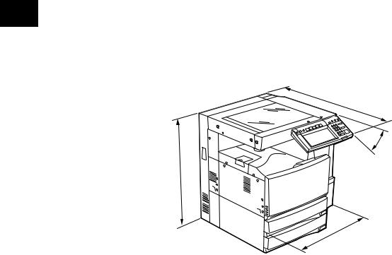
• Dimensions of the equipment ....... See the figure below |
|
W660 x D718 x H739 mm (e-STUDIO350/450) |
||
|
||
|
W660 x D758 x H739 mm (e-STUDIO352/353/452/453) |
|
|
* When the tilt angle of the control panel is 45 degrees. |
|
|
D |
45˚
H
W
Fig. 1-101
e-STUDIO350/352/353/450/452/453 1 - © 2003 - 2008 TOSHIBA TEC CORPORATION All rights reserved
SPECIFICATIONS |
07/11 |
|

1.2 Accessories |
1 |
|
Unpacking/setup instruction |
1 set |
|
|
|
|
Operator’s manual |
4 pcs. (except for MJD) |
|
|
|
|
Operator's manual pocket |
1 pc. |
|
Power cable |
|
1 pc. |
|
|
|
Warranty sheet |
1 pc. (for NAD) |
|
|
|
|
Setup report |
|
1 set (for NAD and MJD) |
|
|
|
Customer satisfaction card |
1 pc. (for MJD) |
|
PM sticker |
|
1 pc. (for MJD) |
|
|
|
Drum (installed inside of the equipment) |
1 pc. |
|
|
|
|
Toner bag |
|
1 pc. |
|
|
|
Toner cartridge |
1 pc. (except for NAD, MJD) |
|
Developer material |
1 pc. (except for NAD,MJD) |
|
|
|
|
Operation panel stopper |
1 pc. |
|
|
|
|
Blind seal |
|
1 pc. |
|
|
|
Rubber plug |
|
4 pcs. |
CD-ROM |
|
4 pcs. |
|
|
|
Platen cover |
|
1 pc. (for CND) |
|
|
|
* Machine version |
|
|
NAD: |
North America |
|
MJD: |
Europe |
|
AUD: |
Australia |
|
ASD: |
Central and South America / Hong Kong / Asia |
|
TWD: |
Taiwan |
|
SAD: |
Saudi Arabia |
|
JPD: |
Japan |
|
CND: |
China |
|
ASU: |
Asia |
|
KRD: |
Korea |
|
© 2003 - 2008 TOSHIBA TEC CORPORATION All rights reserved 1 - |
e-STUDIO350/352/353/450/452/453 |
05/11 |
SPECIFICATIONS |
|
|
1.3 |
Options |
|
|
|
|
1 |
|
|
|
|||
|
1.3.1 e-STUDIO350/450 |
|
|
|
||
|
|
|
|
|
||
|
|
|
|
|
|
|
|
|
Platen Cover |
|
|
KA-3511 PC/PC-C |
|
|
|
|
|
|
||
|
|
Reversing Automatic Document Feeder (RADF) |
|
MR-3015 |
||
|
|
Drawer Module |
|
|
MY-1021 /-C |
|
|
|
|
|
|
|
|
|
|
Paper Feed Pedestal (PFP) |
|
|
KD-1011 /-C |
|
|
|
Large Capacity Feeder (LCF) |
|
|
KD-1012 A4/LT/A4-C |
|
|
|
|
|
|
|
|
|
|
Finisher (Hanging type) |
|
|
MJ-1022 /-C |
|
|
|
Finisher (Console type) |
|
|
MJ-1023 /-C |
|
|
|
|
|
|
|
|
|
|
Finisher (Console saddle stitcher type) |
|
|
MJ-1024 /-C |
|
|
|
Hole Punch Unit |
|
|
MJ-6004 N/E/F/S *1 |
|
|
|
|
|
|
|
|
|
|
Staple Cartridge |
|
|
STAPLE-1600 (for MJ-1022) |
|
|
|
|
|
|
|
STAPLE-2000 (for MJ-1023/1024) |
|
|
|
|
|
|
STAPLE-600 (for MJ-1024) |
|
|
Bridge Kit |
|
|
KN-3520 /-C |
|
|
|
|
|
|
|
|
|
|
Job Separator |
|
|
MJ-5004 /-C |
|
|
|
|
|
|
|
|
|
|
Offset Tray |
|
|
MJ-5005 /-C |
|
|
|
|
|
|
|
|
|
|
Key Copy Counter |
|
|
MU-8, MU-10 |
|
|
|
|
|
|
|
|
|
|
Work Tray |
|
|
KK-3511 |
|
|
|
|
|
|
|
|
|
|
Damp Heater |
|
|
MF-3520 U/E |
|
|
|
|
|
|
|
|
|
|
Fax Board |
|
|
GD-1150 NA/AU/EU/TW/C/AS |
|
|
|
|
|
|
|
|
|
|
2nd Line for Fax Board |
|
|
GD-1160 NA/EU/TW/C |
|
|
|
|
|
|
|
|
|
|
Wireless LAN Adapter |
|
|
GN-1010 |
|
|
|
|
|
|
|
|
|
|
PCI Slot |
|
|
GO-1030 |
|
|
|
|
|
|
|
|
|
|
Scrambler Board |
|
|
GP-1030 |
|
|
|
Printer Kit |
|
|
GM-1010 |
|
|
|
|
|
|
|
|
|
|
Printer/Scanner Kit |
|
|
GM-2010 |
|
|
|
Scanner upgrade Kit |
|
|
GM-3010 |
|
|
|
|
|
|
|
|
|
|
Desk |
|
|
MH-1700 |
|
|
|
Data overwrite kit |
|
|
GP-1050 |
|
|
|
|
|
|
|
|
|
* 1) |
N : North America E : Europe |
F : France |
S : Sweden |
||
Notes:
1.The bridge unit (KN-3520) is necessary for installation of the finisher (MJ-1022, MJ-1023 or
MJ-1024).
2.The finisher (MJ-1023 or MJ-1024) is necessary for installation of the hole punch unit
(MJ-6004N/E/F/S).
3.The PCI slot (GO-1030) is necessary for installation of the scrambler board (GP-1030).
e-STUDIO350/352/353/450/452/453 1 - © 2003 - 2008 TOSHIBA TEC CORPORATION All rights reserved
SPECIFICATIONS |
05/11 |
|
1.3.2 e-STUDIO352/353/452/453 |
|
|
|
|
|
1 |
|
|
|
|
|
Platen cover |
KA-3511PC |
|
|
|
|
||
|
|
|
|
Reversing Automatic Document Feeder (RADF) |
MR-3018 |
|
|
Drawer module |
MY-1021/-C |
|
|
Paper Feed Pedestal (PFP) |
KD-1011/-C |
|
|
Large Capacity Feeder (LCF) |
KD-1012LT/A4/A4-C |
|
|
Finisher (Hanging type) : e-STUDIO352/353 only |
MJ-1022/-C |
|
|
Finisher (Console type) |
MJ-1101 |
|
|
Finisher (Console type) |
MJ-1023/-C |
|
|
Finisher (Console saddle stitcher type) |
MJ-1024/-C |
|
|
Hole punch unit (for MJ-1101) |
MJ-6101N/E/F/S |
|
|
Hole punch unit (for MJ-1023/1024) |
MJ-6004N/E/F/S |
|
|
Staple cartridge |
STAPLE-1600 (for MJ-1022) |
|
|
|
STAPLE-2400 (for MJ-1101) |
|
|
|
STAPLE-2000 (for MJ-1023/1024) |
|
|
|
STAPLE-600 (for saddle stitcher of MJ-1024) |
|
|
Bridge kit |
KN-3520/-C |
|
|
Job separator |
MJ-5004/-C |
|
|
Offset tray |
MJ-5005/-C |
|
|
Work tray |
KK-3511/-C |
|
|
Damp heater |
MF-3520U/E |
|
|
Fax board |
GD-1200NA/EU/AU/AS/C/TW/KR |
|
|
2nd line for fax board |
GD-1160NA/EU-N/C/TW |
|
|
Printer kit |
GM-1060/1061 |
|
|
Printer/Scanner kit |
GM-2060/2061 |
|
|
Scanner kit |
GM-4060 |
|
|
Printer ELK |
GM-1120 |
|
|
Printer/Scanner ELK |
GM-2120 |
|
|
Scannner ELK |
GM-4120 |
|
|
Memory |
GC-1230 |
|
|
Scrambler board |
GP-1040 |
|
|
Wireless LAN module |
GN-1041 |
|
|
Bluetooth module |
GN-2010 |
|
|
Antenna |
GN-3010 |
|
|
Data overwrite kit |
GP-1060 |
|
|
PCI slot |
GO-1060 |
|
|
e-BRIDGE ID Gate (HID iClass) |
KP-2004 |
|
|
e-BRIDGE ID Gate (MIFARE) |
KP-2005 |
|
|
Desk |
MH-1700 |
|
|
Harness kit for coin controller |
GQ-1020 |
|
|
© 2003 - 2008 TOSHIBA TEC CORPORATION All rights reserved 1 - |
e-STUDIO350/352/353/450/452/453 |
08/04 |
SPECIFICATIONS |
|
|
Notes: |
|
|
1 |
|
||
1. |
The bridge kit (KN-3520) is necessary for installation of the finisher (MJ-1022, MJ-1023/1024 |
||
|
|||
|
|
or MJ-1101). |
|
|
2. |
The finisher (MJ-1023/1024) is necessary for installation of the hole punch unit (MJ-6004N/ |
|
|
|
E/F/S). The finisher (MJ-1101) is necessary for installation of the hole punch unit (MJ-6101N/ |
|
|
|
E/F/S). |
|
|
3. |
The PCI slot (GO-1060) is necessary for the installation of the scrambler board (GP-1040). |
|
|
4. |
The antenna (GN-3010) is necessary to enable the wireless LAN module (GN-1041) and |
|
|
|
Bluetooth module (GN-2010). |
|
|
5. |
When the wireless LAN module (GN-1041) and the Bluetooth module (GN-2010) are in- |
|
|
|
stalled, only 1 antenna (GN-3010) can be connected to each. |
|
|
6. |
The Printer kit (GM-1060) or Printer/Scanner kit (GM-2060) does not have a function for |
|
|
|
printing an XPS file. |
|
|
7. |
To enable an XPS file to be printed by the Printer kit (GM-1061) or Printer/Scanner kit |
|
|
|
(GM-2061), the Memory (GC-1230) is required to be installed. |
|
|
8. To enable an XPS file to be printed by the Printer ELK (GM-1120) or Printer/Scanner ELK |
||
|
|
(GM-2120), the Memory (GC-1230) is required to be installed. |
|
e-STUDIO350/352/353/450/452/453 1 - © 2003 - 2008 TOSHIBA TEC CORPORATION All rights reserved
SPECIFICATIONS |
07/11 |
|
1.4 |
Supplies |
|
|
|
|
|
|
|
1 |
||
|
|
|
|
|
|
|
|
|
|
|
|
Drum |
|
OD-3500 |
|
|
|
|
|
|
|
||
Toner bag |
|
PS-TB3520 /E/N *2 |
|
|
|
|
|
|
|
|
|
Toner cartridge |
|
PS-ZT3520 /T/D/C/E *3 (e-STUDIO350/352/450/452) |
|
|
|
|
PS-ZT3520 C *3, PS-ZT4520 /E *3 (e-STUDIO353/453) |
|
|
||
|
|
|
|
||
Developer |
|
D-3500 |
|
|
|
|
|
|
|
|
|
* 2) |
N : Asia |
E : Europe |
NONE : North America |
||
* 3) |
T : Taiwan |
D : Asia |
C : China E : Europe NONE : North America |
||
© 2003 - 2008 TOSHIBA TEC CORPORATION All rights reserved 1 - |
e-STUDIO350/352/353/450/452/453 |
07/11 |
SPECIFICATIONS |
|
SPECIFICATIONS |
STUDIO350/352/353/450/452/453-e |
© 10 - 1 05/11 |
501-1 .Fig |
reserved rights All CORPORATION TEC TOSHIBA 2008 - 2003 |
|
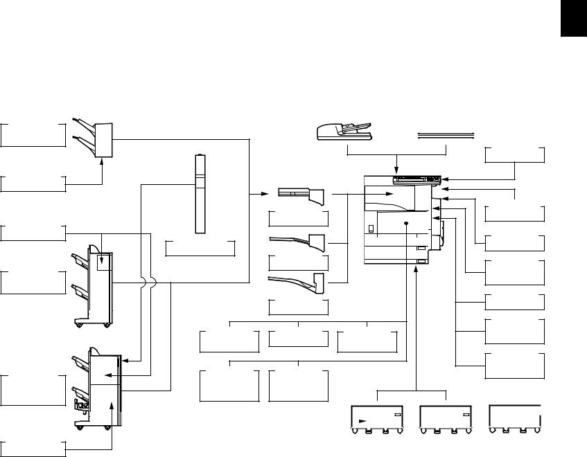
Finisher (Hanging type) MJ-1022
Staple Cartridge
STAPLE-1600
Staple Cartridge
STAPLE-2000
Finisher (Console type) MJ-1023
Finisher
(Console saddle stitcher type)
MJ-1024
Staple Cartridge
STAPLE-600
|
Reversing Automatic |
|
|
|
|
|
|
Document Feeder |
|
|
Platen Cover |
|
|
|
(RADF) |
|
|
|
||
|
|
|||||
|
MR-3015 |
|
|
KA-3511 |
||
|
|
|
|
|
|
|
Work Tray
KK-3511
|
Bridge Kit |
Key Copy Counter |
|
MU-8, MU-10 |
|
|
KN-3520 |
|
|
|
|
Hole Punch Unit |
|
Damp Heater |
|
MF-3520 U/E |
|
MJ-6004 N/E/F/S |
|
|
Job Separator |
|
|
|
Data |
|
|
MJ-5004 |
|
|
overwrite kit |
|
|
|
|
|
|
GP-1050 |
|
Offset Tray |
|
Printer Kit |
|
|
|
GM-1010 |
||
|
MJ-5005 |
|
||
|
|
|
||
|
|
|
Printer/ |
|
Scrambler |
PCI Slot |
Wireless LAN |
Scanner Kit |
|
GM-2010 |
||||
Board |
GO-1030 |
Adapter |
||
|
||||
GP-1030 |
|
GN-1010 |
Scanner |
|
|
|
|
||
|
|
|
Upgrade Kit |
|
FAX Board |
2nd Line for |
|
GM-3010 |
|
GD-1150 |
FAX Board |
|
|
|
NA/AU/EU/ |
GD-1160 |
|
|
|
TW/C/AS |
NA/EU/TW/C |
|
|
|
|
|
|
|
|
|
|
|
|
|
|
|
|
|
|
|
|
|
|
|
|
|
|
|
|
|
|
|
|
|
|
|
|
|
|
|
|
|
|
|
|
|
|
|
|
|
|
|
|
|
|
|
|
|
|
|
|
|
|
|
|
|
|
|
|
|
|
|
|
|
|
|
|
|
|
|
|
|
|
|
|
|
|
|
|
|
|
|
|
|
|
|
|
|
|
|
|
|
|
|
|
|
|
|
|
|
|
|
|
|
|
|
|
|
|
|
|
|
|
|
|
|
|
|
|
|
|
|
|
|
|
|
|
|
|
|
|
|
|
|
|
|
|
|
|
|
|
|
|
|
|
|
|
|
|
|
|
|
|
|
|
|
|
|
|
|
|
|
|
|
|
|
|
|
|
|
|
|
|
|
|
|
|
|
|
|
|
|
|
|
|
|
|
|
|
|
|
|
|
|
|
|
|
|
Drawer Module |
|
|
|
|
|
|
Paper Feed |
|
|
|
|
Large Capacity |
|
|
|
|
|
|
|
|
Desk |
|
|
|
|
|
||||||||||||||||||||||||||||||||||||||||
|
MY-1021 |
|
|
|
|
Pedestal (PFP) |
|
|
|
|
|
Feeder (LCF) |
|
|
|
|
|
|
MH-1700 |
|
|
|
|
|
|||||||||||||||||||||||||||||||||||||||||||
|
|
|
|
|
|
|
|
|
|
|
|
KD-1011 |
|
|
|
KD-1012 A4/LT |
|
|
|
|
|
|
|
|
|
|
|
|
|
|
|
|
|
|
|
|
|||||||||||||||||||||||||||||||
|
|
|
|
|
|
|
|
|
|
|
|
|
|
|
|
|
|
|
|
|
|
|
|
|
|
|
|
|
|
|
|
|
|||||||||||||||||||||||||||||||||||
|
|
|
|
|
|
|
|
|
|
|
|
|
|
|
|
|
|
|
|
|
|
|
|
|
|
|
|
|
|
|
|
|
|||||||||||||||||||||||||||||||||||
|
|
|
|
|
|
|
|
|
|
|
|
|
|
|
|
|
|
|
|
|
|
|
|
|
|
|
|
|
|
|
|
|
|
|
|
|
|
|
|
|
|
|
|
|
|
|
|
|
|
|
|
|
|
|
|
|
|
|
|
|
|
|
|
|
|
|
|
1
.5.1 |
5.1 |
STUDIO350/450-e 1 |
List System |
11 - 1 reserved rights All CORPORATION TEC TOSHIBA 2008 - 2003 © 08/04 |
502-1 .Fig |
SPECIFICATIONS |
STUDIO350/352/353/450/452/453-e |
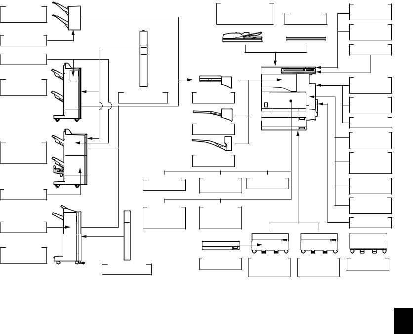
Finisher |
|
Reversing Automatic |
|
e-BRIDGE |
|
|
Document Feeder |
|
ID Gate |
||
(Hanging type) |
|
Platen Cover |
|||
|
(RADF) |
KP-2004 |
|||
MJ-1022 |
|
||||
|
MR-3018 |
KA-3511 |
|
||
|
|
|
|||
|
|
|
e-BRIDGE |
||
|
|
|
|
|
|
|
|
|
|
|
ID Gate |
Staple Cartridge |
|
|
|
|
KP-2005 |
STAPLE-1600 |
|
|
|
|
Work Tray |
|
|
|
|
|
|
Staple Cartridge |
|
|
|
|
KK-3511 |
|
|
|
|
|
|
STAPLE-2000 |
|
|
|
|
|
Finisher |
|
|
|
|
Wireless LAN |
|
|
|
|
Module |
|
(Console type) |
|
|
|
|
|
|
|
|
|
GN-1041 |
|
MJ-1023 |
Hole Punch Unit |
Bridge Kit |
|
|
|
|
|
|
|||
|
MJ-6004 N/E/F/S |
KN-3520 |
|
|
Bluetooth |
|
|
|
|
||
|
|
|
|
|
Module |
|
|
|
|
|
GN-2010 |
|
|
|
|
|
Antenna |
|
|
Job Separator |
|
|
GN-3010 |
|
|
MJ-5004 |
|
|
Printer Kit.ELK |
|
|
|
|
|
|
Finisher |
|
|
|
|
GM-1060/1061 |
|
|
|
|
GM-1120 |
|
(Console saddle |
|
|
|
|
|
|
|
|
|
Printer/ |
|
stitcher type) |
|
Offset Tray |
|
|
|
|
|
|
Scanner Kit.ELK |
||
MJ-1024 |
|
|
|
||
|
MJ-5005 |
|
|
||
|
|
|
|
GM-2060/2061 |
|
|
|
|
|
|
|
|
|
|
|
|
GM-2120 |
|
Damp Heater |
Scrambler |
PCI Slot |
|
Scanner Kit.ELK |
|
Board |
GO-1060 |
|
GM-4060 |
|
|
MF-3520 U/E |
|
|||
Staple Cartridge |
GP-1040 |
|
|
GM-4120 |
|
|
|
|
|||
STAPLE-600 |
|
|
|
|
Data |
|
|
|
|
|
|
|
FAX Board |
2nd Line for |
|
|
Overwrite Kit |
|
|
|
GP-1060 |
||
|
GD-1200 |
FAX Board |
|
|
|
|
|
|
Memory |
||
|
NA/EU/AU/AS/ |
GD-1160 |
|
|
|
Staple Cartridge |
|
|
GC-1230 |
||
C/TW/KR |
NA/EU-N/TW/C |
|
|
||
STAPLE-2400 |
|
|
|
||
|
|
|
|
|
|
Finisher |
|
|
|
|
|
(Console type) |
|
|
|
|
|
MJ-1101 |
|
Drawer Module |
Paper Feed |
Large Capacity |
Desk |
|
Hole Punch Unit |
MY-1021 |
Pedestal (PFP) |
Feeder (LCF) |
MH-1700 |
|
MJ-6101 N/E/F/S |
|
KD-1011 |
KD-1012 A4/LT |
|
STUDIO352/353/452/453-e 2.5.1
1

1
e-STUDIO350/352/353/450/452/453 |
1 - 12 © 2003 - 2008 TOSHIBA TEC CORPORATION All rights reserved |
SPECIFICATIONS |
|

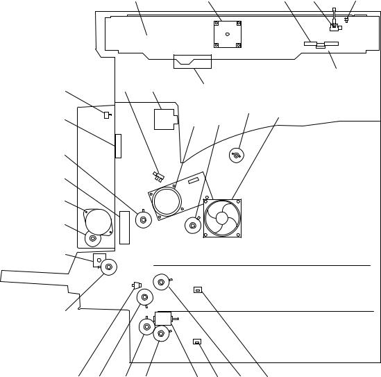
2. OUTLINE OF THE MACHINE
2.1 Sectional View |
2 |
|
|
2 |
4 |
|
|
|
|
7 |
|
||||
|
|
|
|
|
|
|
|
|
|
|
|
|
|
|
|
|
|
|
|
|
|
|
|
|
|
|
|
|
|
|
|
|
|
|
|
|
|
|
|
|
|
|
|
|
|
|
|
|
|
|
|
|
|
|
|
|
|
|
|
5 |
|
3 |
|
5 ,5 3 4 2 27 57 45 5 5 2 |
|
|||||
|
|
|
|
|
||||||
70 |
7 |
3 |
4 47 |
|
|
|
|
|
52 |
|
0 43 4 |
|
|
|
|
|
4 |
|
|||
|
|
|
44 0 |
|
|
|
|
|||
|
|
|
|
|
|
3 |
|
|||
|
|
|
|
|
|
|
|
|||
|
|
|
|
|
|
|
|
|
|
|
|
|
|
|
54 |
|
|
|
7 |
|
|
|
|
|
|
|
|
|
|
|
||
|
|
|
|
|
|
|
|
|
|
|
2 |
|
|
|
|
|
|
|
|
40 |
|
|
|
|
|
|
|
|
|
2 |
|
|
|
|
|
|
|
|
|
|
|
|
|
|
|
|
|
|
|
|
|
|
42 |
|
|
|
|
|
|
|
|
|
|
55 |
|
72 |
|
|
|
|
|
|
|
|
23 |
|
|
|
|
|
|
|
|
|
23 |
|
|
|
|
|
|
|
|
|
|
|
|
|
|
|
|
|
|
|
|
|
32 |
|
|
|
|
|
|
|
|
|
|
|
|
|
|
|
|
|
|
|
|
|
24 |
|
|
5 |
|
|
|
|
|
|
|
|
30 |
|
|
|
|
|
|
|
|
|
25 |
|
|
|
|
|
|
|
|
|
|
|
3 |
|
53 |
|
|
|
|
|
|
|
|
37 |
|
|
|
|
|
|
|
|
|
|
|
|
22 |
|
|
|
20,2 |
3 |
4 |
|
|
|
|
|
|
|
|
|
|
|
|
|||
|
|
|
|
|
|
|
5 |
|
|
|
|
|
|
|
|
|
|
|
34 |
33 |
|
7 |
|
|
|
20,2 |
3 |
|
4 |
2 35 3 |
|
|
|
|
|
|
|
|
|
||||
|
|
|
|
|
|
5 |
|
|
|
|
|
|
|
|
|
|
|
|
|
|
|
|
50 |
4 |
|
|
|
|
|
|
|
|
|
|
|
|
Fig. 2-101 |
|
|
|
|
|
|
© 2003 - 2008 TOSHIBA TEC CORPORATION All rights reserved 2 - |
e-STUDIO350/352/353/450/452/453 |
|
OUTLINE OF THE MACHINE |
|
|
1 |
Original glass |
37 |
Bypass paper sensor |
|
|
|
|
|
|
|
|
2 |
ADF original glass |
38 |
Bypass separation roller |
2 |
|
|
|
|
|
|
3 |
Mirror-1 |
39 |
Temperature/humidity sensor |
|
|
|
4 |
Mirror-2 |
40 |
Transfer charger |
|
|||||
|
|
|
|
|
|
|
|
5 |
Mirror-3 |
41 |
Separation charger |
|
|
|
|
|
|
|
|
6 |
Reflector |
42 |
Drum |
|
|
|
|
|
|
|
|
7 |
Lens |
43 |
Developer unit |
|
|
|
|
|
|
|
|
8 |
Exposure lamp |
44 |
Cleaning blade |
|
|
|
|
|
|
|
|
9 |
Automatic original detection sensor |
45 |
Recovery blade |
|
|
|
|
|
|
|
|
10 |
Toner cartridge switch |
46 |
Main charger |
|
|
|
|
|
|
|
|
11 |
Laser unit |
47 |
Discharge LED |
|
|
|
|
|
|
|
|
12 |
Laser unit cooling fan |
48 |
Drum thermistor |
|
|
|
|
|
|
|
|
13 |
Drawer pickup roller |
49 |
Drum damp heater thermostat |
|
|
|
|
|
|
|
|
14 |
Drawer feed roller |
50 |
Drum damp heater |
|
|
|
|
|
|
|
|
15 |
Drawer separation roller |
51 |
Separation finger for drum |
|
|
|
|
|
|
|
|
16 |
Drawer transport roller |
52 |
Toner bag full detection sensor-2 |
|
|
|
|
|
|
|
|
17 |
Drawer |
53 |
Auto-toner sensor |
|
|
|
|
|
|
|
|
18 |
Drawer tray |
54 |
Toner recovery auger |
|
|
|
|
|
|
|
|
19 |
Drawer tray-up sensor |
55 |
Developer sleeve (magnetic roller) |
|
|
|
|
|
|
|
|
20 |
Drawer empty sensor |
56 |
Fuser roller |
|
|
|
|
|
|
|
|
21 |
Drawer paper stock sensor |
57 |
Pressure roller |
|
|
|
|
|
|
|
|
22 |
Drawer damp heater (JPD only) |
58 |
Cleaning roller |
|
|
|
|
|
|
|
|
23 |
Registration roller |
59 |
IH coil |
|
|
|
|
|
|
|
|
24 |
Registration sensor |
60 |
Main thermistor / Edge thermistor |
|
|
|
|
|
|
|
|
25 |
Upper drawer feed sensor |
61 |
Separation finger for fuser roller |
|
|
|
|
|
|
|
|
26 |
Lower drawer feed sensor |
62 |
Separation finger for pressure roller |
|
|
|
|
|
|
|
|
27 |
Exit sensor |
63 |
Exit roller |
|
|
|
|
|
|
|
|
28 |
ADU upper transport roller |
64 |
Fuser thermostat |
|
|
|
|
|
|
|
|
29 |
ADU middle transport roller |
65 |
Middle fan |
|
|
|
|
|
|
|
|
30 |
ADU lower transport roller |
66 |
Exhaust fan |
|
|
|
|
|
|
|
|
31 |
ADU entrance sensor |
67 |
Sub-separation fan |
|
|
|
|
|
|
|
|
32 |
ADU exit sensor |
68 |
Power supply cooling fan |
|
|
|
|
|
|
|
|
33 |
Bypass pickup roller |
69 |
Main switch |
|
|
|
|
|
|
|
|
34 |
Bypass feed roller |
70 |
Front cover opening/closing switch |
|
|
|
|
|
|
|
|
35 |
Bypass feed sensor |
71 |
Cover opening/closing interlock switch |
|
|
|
|
|
|
|
|
36 |
Bypass tray |
72 |
Polygonal motor |
|
|
|
|
|
|
e-STUDIO350/352/353/450/452/453 2 - © 2003 - 2008 TOSHIBA TEC CORPORATION All rights reserved
OUTLINE OF THE MACHINE |
04/05 |
|
5 |
|
2 |
|
|
|
3 |
2 |
||||||
|
|
|
|
|
|
|
|
|
|
|
|
|
|
|
|
|
|
|
|
|
|
|
|
|
|
|
|
|
|
|
|
|
|
|
|
|
|
|
|
|
|
|
|
|
|
|
|
|
|
|
|
|
|
|
|
|
|
|
|
|
|
|
|
|
|
|
|
|
|
|
|
|
|
|
|
|
|
|
|
|
|
|
|
|
|
|
|
|
|
|
|
|
|
|
|
|
|
|
|
|
|
|
|
|
|
|
|
|
|
|
|
4
4 |
3 |
2 |
7 |
|
|
|
|
||
|
|
|
|
|
5 |
|
|
0 |
|
|
|
|
2
7
20
|
|
|
|
2 23 |
22 24 |
25 2 27 2 |
|
Fig. 2-102
© 2003 - 2008 TOSHIBA TEC CORPORATION All rights reserved 2 - |
e-STUDIO350/352/353/450/452/453 |
|
OUTLINE OF THE MACHINE |
|
|
1 |
Platen sensor |
15 |
Fuser unit cooling fan |
|
|
|
|
|
|
|
|
2 |
Scan motor |
16 |
Registration clutch |
2 |
|
|
|
|
|
|
3 |
Carriage home position sensor |
17 |
ADU motor |
|
|
|
4 |
Scanner damp heater (Left) |
18 |
ADU clutch |
|
|||||
|
|
|
|
|
|
|
|
5 |
Scanner damp heater (Right) |
19 |
Bypass pickup solenoid |
|
|
|
|
|
|
|
|
6 |
Scanner damp heater thermostat |
20 |
Bypass feed clutch |
|
|
|
|
|
|
|
|
7 |
IH board cooling fan |
21 |
Side cover opening/closing switch |
|
|
|
|
|
|
|
|
8 |
Developer unit cooling fan-1 |
22 |
Transport clutch (High speed) |
|
|
|
|
|
|
|
|
9 |
Toner motor |
23 |
Transport clutch (Low speed) |
|
|
|
|
|
|
|
|
10 |
Developer drive clutch |
24 |
Lower drawer feed clutch |
|
|
|
|
|
|
|
|
11 |
Main motor |
25 |
Tray-up motor |
|
|
|
|
|
|
|
|
12 |
Exit motor |
26 |
Drawer detection switch |
|
|
|
|
|
|
|
|
13 |
Toner bag full detection sensor-1 |
27 |
Upper drawer feed clutch |
|
|
|
|
|
|
|
|
14 |
ADU opening/closing switch |
28 |
Developer unit cooling fan-2 |
|
|
|
|
|
|
e-STUDIO350/352/353/450/452/453 |
2 - |
© 2003 - 2008 TOSHIBA TEC CORPORATION All rights reserved |
OUTLINE OF THE MACHINE |
|
|
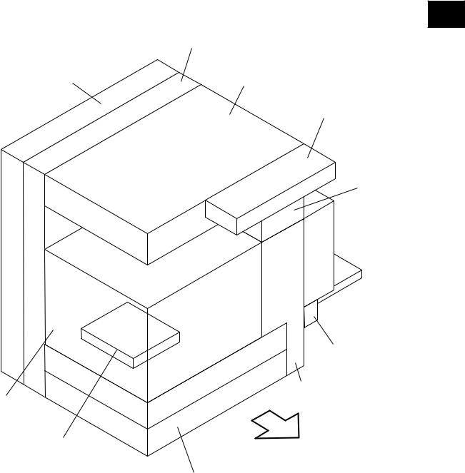
2.2 Electric Parts Layout
[A] Unit construction
2
Drive unit
PC board unit |
Scanner unit |
Control panel unit
Fuser unit
 Automatic
duplexing unit
Bypass unit
Transport unit
Process unit
Laser unit |
Front side |
|
|
|
Paper feeder unit |
Fig. 2-201
© 2003 - 2008 TOSHIBA TEC CORPORATION All rights reserved 2 - |
e-STUDIO350/352/353/450/452/453 |
|
OUTLINE OF THE MACHINE |

[B] Scanner unit
(B-1) Motor, sensor, lamp
2
A4 series
S5
M1
S4
S7
S6
EXP |
S2 |
S1 |
|
S3 |
Front side |
||
|
Fig. 2-202-1
LT series
S5
M1
S4
S7
S6
EXP |
S2 |
S3 |
Front side |
Fig. 2-202-2
e-STUDIO350/352/353/450/452/453 |
2 - |
© 2003 - 2008 TOSHIBA TEC CORPORATION All rights reserved |
OUTLINE OF THE MACHINE |
|
|
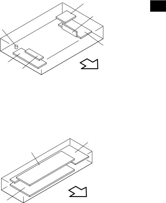
(B-2) PC board, heater, thermostat, other part
THMO2*
DH1*
INV
Fig. 2-203
*ASD/AUD/CND/SAD/TWD models : Standard NAD/MJD models : Option
[C]Control panel unit
LCD
DSP
Fig. 2-204
DH2* |
2 |
|
|
|
CCD |
SLG
Front side
KEY
Front side
© 2003 - 2008 TOSHIBA TEC CORPORATION All rights reserved 2 - |
e-STUDIO350/352/353/450/452/453 |
|
OUTLINE OF THE MACHINE |
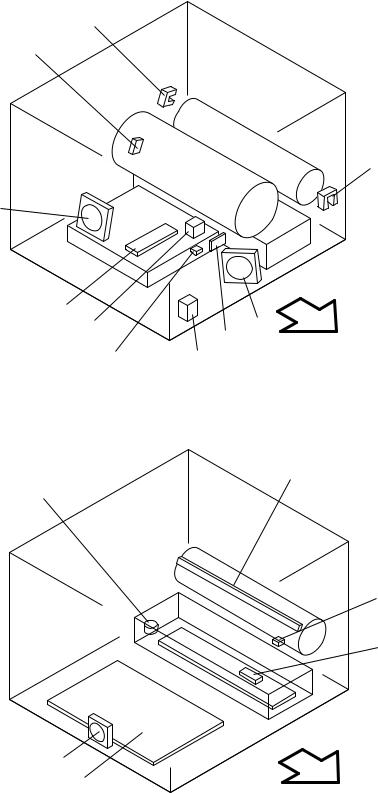
[D] Process unit
(D-1) Motor, sensor, switch, PC board
2 |
S9 |
|
S8 |
|
S10
M8
LRL
S32 |
S12 |
M9 |
|
|
|||
|
Front side |
||
S31 |
S30 |
||
|
|||
|
Fig. 2-205 |
|
(D-2) Motor, sensor, lamp, heater, thermistor, thermostat
ERS
THMO3*
THM3
S11
 DH3*
DH3*
M16 |
|
|
PS |
Front side |
|
* ASD/AUD/CND/SAD/TWD models : Standard |
||
|
||
NAD/MJD models : Option |
|
|
Fig. 2-206 |
|
e-STUDIO350/352/353/450/452/453 |
2 - |
© 2003 - 2008 TOSHIBA TEC CORPORATION All rights reserved |
OUTLINE OF THE MACHINE |
|
|
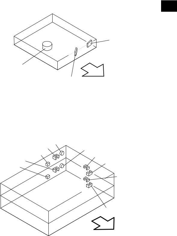
[E] Laser unit
2
SNS
M2
LDR
Front side
Fig. 2-207
[F] Paper feeder unit
|
|
CLT1 |
|
S20 |
CLT2 |
|
|
|
|
S22 |
S16 |
S21 |
|
|
|
|
S18
S23
S17
S19
Front side
Fig. 2-208
© 2003 - 2008 TOSHIBA TEC CORPORATION All rights reserved 2 - |
e-STUDIO350/352/353/450/452/453 |
|
OUTLINE OF THE MACHINE |
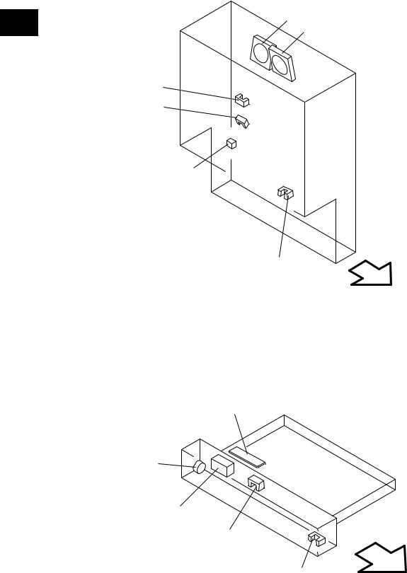
[G] Transport unit
2 |
M10 |
|
M11 |
||
|
S13
S14
S33
S15
Front side
Fig. 2-209
[H] Bypass unit
SFB
CLT3
SOL1 |
|
|
S24 |
|
S25 |
|
Front side |
|
Fig. 2-210 |
e-STUDIO350/352/353/450/452/453 |
2 - 10 © 2003 - 2008 TOSHIBA TEC CORPORATION All rights reserved |
OUTLINE OF THE MACHINE |
|
Loading...