

Toshiba 35UFV-ND, RAS-25, 35S3AVP-ND Installation Manual
1112150205
Indoor unit
RAS-25, 35UFV-ND
Outdoor unit
RAS-25, 35S3AVP-ND
AIR CONDITIONER (SPLIT TYPE)
INSTALLATION MANUAL
ENGLISH
SVENSKA
SUOMI
NORSK

INNEHÅLL
SÄKERHETSANVISNINGAR ....................................................................... 1
INSTALLATIONSSCHEMA FÖR INOMHUS- OCH
UTOMHUSENHETEN ................................................................................... 3
Valfria Installationskomponenter ...............................................................3
INOMHUSENHETEN .................................................................................... 4
Plats för Montering .................................................................................... 4
Skära ut ett Hål och Fästa Monteringsplåten ............................................ 4
Så här monteras inomhusenheten ............................................................ 5
Dold montering ..........................................................................................6
UTOMHUSENHETEN ................................................................................... 7
Plats för Montering .................................................................................... 7
Försiktighetsåtgärder vid Installation i Områden med Snöfall och Kalla
Temperaturer ............................................................................................. 7
Anslutning av Köldmedierör .......................................................................7
Vakuumsugning ......................................................................................... 8
Ledningsdragningar ................................................................................... 8
Elarbeten ...................................................................................................8
ÖVRIGT ......................................................................................................... 9
Kontrollera Gasläckor ................................................................................ 9
Inställning av Fjärrkontrollens Omkopplare ............................................... 9
Fjärrkontroll A-B Val .................................................................................. 9
Testkörning ................................................................................................ 9
Inställning av Omstart ................................................................................ 9
SV
SISÄLLYSLUETTELO
VAROTOIMENPITEET .................................................................................. 1
SISÄ- JA ULKOYKSIKKÖJEN ASENNUSKAAVIO ....................................3
Lisävarusteena Saatavat Asennusosat .....................................................3
SISÄYKSIKKÖ .............................................................................................. 4
Asennuspaikka ..........................................................................................4
Aukon Tekeminen ja Asennuslevyn Kiinnittäminen ................................... 4
Sisäyksikön asennus ................................................................................. 5
Piilotettu asennus ...................................................................................... 6
ULKOYKSIKKÖ ............................................................................................ 7
Asennuspaikka ..........................................................................................7
Huomiot Asennuksesta Alueille, Joissa on Lumisadetta ja Kylmiä
Lämpötiloja ................................................................................................ 7
Kylmänesteputkien Liittäminen ..................................................................7
Tyhjentäminen ........................................................................................... 8
Johtoliitännät .............................................................................................8
Sähkötyöt ...................................................................................................8
MUUT ............................................................................................................ 9
Kaasuvuototesti ......................................................................................... 9
Kauko-ohjaimen Valitsinkytkimen Säätäminen .......................................... 9
Kauko-ohjaimen A-B Valinta ...................................................................... 9
Koekäyttö ...................................................................................................9
Automaattisen Uudelleenkäynnistyksen Asettaminen ............................... 9
FI
INNHOLD
SIKKERHETSREGLER ................................................................................ 1
KOBLINGSSKJEMA FOR INNE- OG UTENDØRSENHETEN ....................3
Ekstrautstyr ................................................................................................3
INNENHETEN ............................................................................................... 4
Plassering .................................................................................................. 4
Lage et Hull og Montere Montasjeplaten ................................................... 4
Slik Monterer du Innendørsenheten ..........................................................5
Skjult Montering .........................................................................................6
UTENDØRSENHET ...................................................................................... 7
Montasjested .............................................................................................7
Forholdsregler ved Installasjon i Områder med Snø og Lave
Temperaturer ............................................................................................. 7
Tilkobling av Kjølerørene ........................................................................... 7
Evakuering .................................................................................................8
Tilkobling av Ledninger .............................................................................. 8
Elektrisk Arbeid .......................................................................................... 8
ANNET .......................................................................................................... 9
Gasslekkasjetest .......................................................................................9
Stille Fjernkontrollbryteren ......................................................................... 9
Fjernkontroll A-B Valg ................................................................................ 9
Testdrift ...................................................................................................... 9
Innstillinger for Auto Restart ......................................................................9
NO
CONTENTS
PRECAUTIONS FOR SAFETY ..................................................................... 1
INSTALLATION DIAGRAM OF INDOOR AND OUTDOOR UNITS ............. 3
Optional Installation Parts .......................................................................... 3
INDOOR UNIT ............................................................................................... 4
Installation Place ....................................................................................... 4
Cutting a Hole and Mounting Installation Plate .......................................... 4
How to Install Indoor Unit .......................................................................... 5
Concealed Installation ............................................................................... 6
OUTDOOR UNIT ........................................................................................... 7
Installation Place ....................................................................................... 7
Precautions about Installation in Regions with Snowfall and Cold
Temperatures ............................................................................................ 7
Refrigerant Piping Connection ................................................................... 7
Evacuating ................................................................................................ 8
Wiring Connection ..................................................................................... 8
Electrical Work ........................................................................................... 8
OTHERS ........................................................................................................ 9
Gas Leak Test ...........................................................................................9
Setting of Remote Control Selector Switch ............................................... 9
Remote Control A-B Selection ................................................................... 9
Test Operation .......................................................................................... 9
Auto Restart Setting ................................................................................. 9
EN

PRECAUTIONS FOR SAFETY
PRECAUTIONS FOR SAFETY
Be sure to read this installation manual carefully before installing.
Recommend to the owner to perform maintenance periodically when using over long periods of time.
Be sure to follow the precautions provided here to avoid safety risks. The symbols and their meanings are shown below.
DANGER : It indicates that incorrect use of this unit can result in a high possibility of severe injury (*1) or death.
WARNING : It indicates that incorrect use of this unit may cause severe injury or death.
CAUTION : It indicates that incorrect use of this unit may cause personal injury (*2), or property damage (*3).
*1 : A severe injury refers to blindness, injury, burns (hot or cold), electrical shock, bone fracture, or poisoning that leaves aftereffects and
requires hospitalization or extended out-patient treatment.
*2 : Personal injury means a slight accident, burn, or electrical shock which does not require admission or repeated hospital treatment.
*3 : Property damage means greater damage which affects assets or resources.
For general public use
Power supply cord of parts of appliance for outdoor use shall be at least polychloroprene sheathed fl exible cord (design H07RN-F) or cord designation
60245 IEC66 (1.5 mm
2
or more) (Shall be installed in accordance with national wiring regulations).
New refrigerant air conditioner installation
CAUTION
• THIS AIR CONDITIONER USES THE NEW HFC REFRIGERANT (R410A), WHICH DOES NOT DESTROY THE OZONE LAYER.
R410A refrigerant is apt to be affected by impurities such as water, oxidizing membranes, and oils because the pressure of R410A refrigerant is approx.
1.6 times of refrigerant R22. As well as the adoption of this new refrigerant, refrigerating machine oil has also been changed. Therefore, during installation
work, be sure that water, dust, former refrigerant, or refrigerating machine oil does not enter the refrigeration cycle of a new-refrigerant air conditioner.
To avoid mixing refrigerant and refrigerating machine oil, the sizes of charging port connecting sections on the main unit are different from those for the
conventional refrigerant, and different size tools are also required. For connecting pipes, use new and clean piping materials with highpressure withstand
capabilities, designed for R410A only, and ensure that water or dust does not enter. Moreover, do not use any existing piping as its pressure withstand
may be insuffi cient and may contain impurities.
DANGER
• FOR USE BY QUALIFIED PERSONS ONLY.
• MEANS FOR DISCONNECTION FROM THE SUPPLY HAVING A CONTACT SEPERATION OF AT LEAST 3 mm IN ALL POLES MUST BE
INCORPORATED IN THE FIXED WIRING.
• TURN OFF MAIN POWER SUPPLY BEFORE ATTEMPTING ANY ELECTRICAL WORK. MAKE SURE ALL POWER SWITCHES ARE OFF.
FAILURE TO DO SO MAY CAUSE ELECTRIC SHOCK.
• CONNECT THE CONNECTING CABLE CORRECTLY. IF THE CONNECTING CABLE IS CONNECTED WRONGLY, ELECTRIC PARTS MAY BE
DAMAGED.
• CHECK THE EARTH WIRE THAT IT IS NOT BROKEN OR DISCONNECTED BEFORE INSTALLATION.
• DO NOT INSTALL NEAR CONCENTRATIONS OF COMBUSTIBLE GAS OR GAS VAPORS. FAILURE TO FOLLOW THIS INSTRUCTION CAN
RESULT IN FIRE OR EXPLOSION.
• TO PREVENT OVERHEATING THE INDOOR UNIT AND CAUSING A FIRE HAZARD, PLACE THE UNIT WELL AWAY (MORE THAN 2 M) FROM
HEAT SOURCES SUCH AS RADIATORS, HEATERS, FURNACE, STOVES, ETC.
• WHEN MOVING THE AIR CONDITIONER FOR INSTALLING IT IN ANOTHER PLACE AGAIN, BE VERY CAREFUL NOT TO GET THE SPECIFIED
REFRIGERANT (R410A) WITH ANY OTHER GASEOUS BODY INTO THE REFRIGERATION CYCLE. IF AIR OR ANY OTHER GAS IS MIXED IN
THE REFRIGERANT, THE GAS PRESSURE IN THE REFRIGERATION CYCLE BECOMES ABNORMALLY HIGH AND IT RESULTINGLY CAUSES
BURST OF THE PIPE AND INJURIES ON PERSONS.
• IN THE EVENT THAT THE REFRIGERANT GAS LEAKS OUT OF THE PIPE DURING THE INSTALLATION WORK, IMMEDIATELY LET FRESH AIR
INTO THE ROOM. IF THE REFRIGERANT GAS IS HEATED BY FIRE OR SOMETHING ELSE, IT CAUSES GENERATION OF POISONOUS GAS.
• WHEN INTALLING OR RE-INSTALLING THE AIR CONDITIONER, DO NOT INJECT AIR OR OTHER SUBSTANCES BESIDES THE DESIGNATED
REFRIGERANT “R410A” INTO THE REFRIGERATING CYCLE. IF AIR OR OTHER SUBSTANCES ARE MIXED, AN ABNORMAL PRESSURE CAN
OCCUR IN THE REFRIGERATING CYCLE, AND THIS CAN CAUSE AN INJURY DUE TO A PIPE RUPTURE.
EN
SV
FI
NO
1
CAUTION
• Please read this installation manual carefully before installing the unit. It contains further important instructions for proper installation.
• Exposure of unit to water or other moisture before installation could result in electric shock. Do not store it in a wet basement or expose to rain or water.
• After unpacking the unit, examine it carefully for possible damage.
• Do not install in a place that can increase the vibration of the unit. Do not install in a place that can amplify the noise level of the unit or where noise and
discharged air might disturb neighbors.
• This appliance must be connected to the main power supply by means of a circuit breaker depending on the place where the unit is installed. Failure to
do so may cause electrical shock.
• Follow the instructions in this installation manual to arrange the drain pipe for proper drainage from the unit. Ensure that drained water is discharged.
Improper drainage can result in water leakage, causing water damage to furniture.
• Tighten the fl are nut with a torque wrench using the prescribed method. Do not apply excess torque. Otherwise, the nut may crack after a long period of
usage and it may cause the leakage of refrigerant.
• Wear gloves (heavy gloves such as cotton gloves) for installation work. Failure to do so may cause personal injury when handling parts with sharp
edges.
• Do not touch the air intake section or the aluminum fi ns of the outdoor unit. It may cause injury.
• Do not install the outdoor unit in a place which can be a nest for small animals. Small animals could enter and contact internal electrical parts, causing a
failure or fi re.
• Request the user to keep the place around the unit tidy and clean.
• Make sure to conduct a trial operation after the installation work, and explain how to use and maintain the unit to the customer in accordance with the
manual. Ask the customer to keep the operation manual along with the installation manual.
REQUIREMENT OF REPORT TO THE LOCAL POWER SUPPLIER
Please make absolutely sure that the installation of this appliance is reported to the local power supplier before installation. If you experience any problems
or if the installation is not accepted by the supplier, the service agency will take adequate countermeasures.
WARNING
• Installation work must be requested from the supplying retail dealership or professional vendors. Self-installation may cause water leakage, electrical
shock, or fi re as a result of improper installation.
• Specifi ed tools and pipe parts for model R410A are required, and installation work must be done in accordance with the manual. HFC type refrigerant
R410A has 1.6 times more pressure than that of conventional refrigerant (R22). Use the specifi ed pipe parts, and ensure correct installation, otherwise
damage and/or injury may be caused. At the same time, water leakage, electrical shock, and fi re may occur.
• Be sure to install the unit in a place which can suffi ciently bear its weight. If the load bearing of the unit is not enough, or installation of the unit is
improper, the unit may fall and result in injury.
• Electrical work must be performed by a qualifi ed electrical engineer in accordance with the code governing such installation work, internal wiring
regulations, and the manual. A dedicated circuit and the rated voltage must be used. Insuffi cient power supply or improper installation may cause
electrical shock or fi re.
• Use a cabtyre cable to connect wires in the indoor/outdoor units. Midway connection, stranded wire, and single-wire connections are not allowed.
Improper connection or fi xing may cause a fi re.
• Wiring between the indoor unit and outdoor units must be well shaped so that the cover can be fi rmly placed. Improper cover installation may cause
increased heat, fi re, or electrical shock at the terminal area.
• Be sure to use only approved accessories or the specifi ed parts. Failure to do so may cause the unit to fall, water leakage, fi re or electrical shock.
• After the installation work, ensure that there is no leakage of refrigerant gas. If the refrigerant gas leaks out of the pipe into the room and is heated by
fi re or something else from a fanheater, stove or gas range, it causes generation of poisonous gas.
• Make sure the equipment is properly earthed. Do not connect the earth wire to a gas pipe, water pipe, lightning conductor, or telephone earth wire.
Improper earth work may be the cause of electrical shock.
• Do not install the unit where fl ammable gas may leak. If there is any gas leakage or accumulation around the unit, it can cause a fi re.
• Do not select a location for installation where there may be excessive water or humidity, such as a bathroom. Deterioration of insulation may cause
electrical shock or fi re.
• Installation work must be performed following the instructions in this installation manual. Improper installation may cause water leakage, electrical shock
or fi re. Check the following items before operating the unit.
- Be sure that the pipe connection is well placed and there are no leaks.
- Check that the service valve is open. If the service valve is closed, it may cause overpressure and result in compressor damage. At the same time, if
there is a leak in the connection part, it may cause air suction and overpressure, resulting burst or injury.
• In pump down operations, ensure to perform the following procedures.
- Do not inject air into the refrigeration cycle.
- Be sure to close both service valves and stop the compressor before removing the refrigerant pipe. If removing the refrigerant pipe while the
compressor is operating with the service valves opened, it may cause to air absorbed and abnormal high pressure inside the refrigeration cycle and
resulting burst or injury.
• Do not modify the power cable, connect the cable midway, or use a multiple outlet extension cable. Doing so may cause contact failure, insulation
failure, or excess current, resulting in fi re or electrical shock.
• If you detect any damage, do not install the unit. Contact your supplying dealer immediately.
• Never modify this unit by removing any of the safety guards or bypassing any of the safety interlock switches.
2
$
%
&
'
Vinyl tape
Apply after carrying
out a drainage test.
600 mm or more only
when unobstructed
to the front and both
sides.
Extension
drain hose
(Not available,
provided by installer)
100 mm or more
100 mm or more
600 mm or more
600 mm or more
600 mm or more
Saddle
1 Installation plate
50 mm or more
50 mm or more
Shield pipe
Air fi lter
70 mm or more
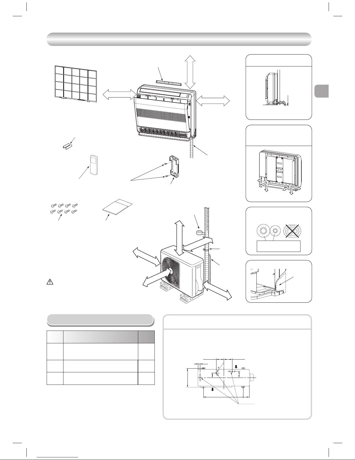
INSTALLATION DIAGRAM OF INDOOR AND OUTDOOR UNITS
INSTALLATION DIAGRAM OF INDOOR AND OUTDOOR UNITS
Part
code
Parts name Q’ty
A
Refrigerant piping
Liquid side : ∅6.35 mm
Gas side : ∅9.52 mm
One
each
B
Pipe insulating material
(polyethylene foam, 8 mm thick)
1
C
Putty, PVC tapes
One
each
Optional Installation Parts
• Secure the outdoor unit with fi xing bolts and nuts if the unit is likely to be exposed
to a strong wind.
• Use ∅8 mm or ∅10 mm anchor bolts and nuts.
• If it is necessary to drain the defrost water, attach drain nipple and cap water proof
to the bottom plate of the outdoor unit before installing it.
Fixing bolt arrangement of outdoor unit
RAS-25, 35S3AVP-ND
3 Batteries
6 Flat head
wood screw
4 Remote control holder
Remark :
• Detail of accessory and installation
parts can see in the accessory sheet.
When installing the outdoor unit,
leave open in at least two of direction
(A), (B), (C) and (D) shown in the
fi gure on the right.
Do not allow the drain hose to get
slack.
Make sure to run the drain hose
sloped downward.
The auxiliary piping can be
connected to the left, rear left, rear
right, right, bottom right or bottom
left.
Insulate the refrigerant pipes
separately with insulation, not
together.
8 mm thick heat resisting
polyethylene foam
Cut the piping
hole sloped
slightly.
Right
Rear right
Left
Bottom right
Rear left
Bottom left
Cut dot-line area
In case of right or left piping
* Drain nipple and cap
water proof are packed
in outdoor unit.
X When using a multi-system outdoor unit is used, refer to the installation manual
provided with the model concerned.
Air outlet
Drain outlet
Air inlet
108 mm
600 mm
28 mm
25 mm
90 mm
125 mm
320 mm
86 mm
102 mm
CAUTION
Install in rooms that are 13 m3 or larger.
If a leak of refrigerator gas occurs
inside the room, an oxygen defi ciency
can occur.
5 Mounting screw 7 Insulation sheet
2 Wireless remote control
EN
SV
FI
NO
3
7 m
60
90
7 m
7 m
45
45
60100
45
45
45
45
100 70
60
100
230
150
(700)
(600)
(205)
15
15
90
15
15
272
560
590
670
INDOOR UNIT
INDOOR UNIT
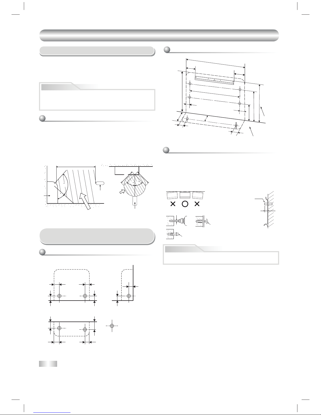
Installation Place
Remote control
• A place where there are no obstacles such as a curtain that may block the
signal from the remote control.
• Do not install the remote control in a place exposed to direct sunlight or
close to a heating source such as a stove.
• Keep the remote control at least 1 m apart from the nearest TV set or
stereo equipment (This is necessary to prevent image disturbances or
noise interference).
• The location of the remote control should be determined as shown below.
Cutting a Hole and Mounting
Installation Plate
When the installation plate is directly mounted
on the wall
1. Securely fi t the installation plate onto the wall by screwing it in the upper
and lower parts to hook up the indoor unit.
2. To mount the installation plate on a concrete wall with anchor bolts, use
the anchor bolt holes as illustrated in the below fi gure.
3. Install the installation plate horizontally in the wall.
NOTE
• When drilling a wall that contains a metal lath, wire lath or metal plate, be
sure to use a pipe hole brim ring sold separately.
• A place which provides the spaces around the indoor unit as shown in the
diagram.
• A place where there are no obstacles near the air inlet and outlet.
• A place which allows easy installation of the piping to the outdoor unit.
• A place which allows the front panel to be opened.
• In case of block, brick, concrete or similar type walls, make ∅5 mm holes
in the wall.
• Insert clip anchors for appropriate mounting screws 5.
Installation plate
(Keep horizontal direction)
∅5 mm hole
Clip anchor
(local parts)
Anchor bolt
Projection
15 mm or less
Cutting a hole
Mounting the installation plate and screw position
CAUTION
• Direct sunlight to the indoor unit’s wireless receiver should be avoided.
• The microprocessor in the indoor unit should not be too close to RF
noise sources.
(For details, see the owner’s manual)
1. After determining the pipe hole position, drill the pipe hole (∅65 mm) at a
slight downward slant to the outdoor side.
5 Mounting screw
∅4 mm x 25 s
CAUTION
Failure to fi rmly install the unit may result in personal injury and property
damage if the unit falls.
Remote
control
Indoor unit
Reception range
(Side view) (Top view)
Reception range
* : Axial distance
: Pipe hole (∅65 mm)
(Side piping)(Rear piping)
(Bottom piping)
(Unit : mm)
Floor
Wall
Remote control
4
47
49
210
163
64
29
85
66
40
100
108
49
542 58
4085
112
148
R45
120
How to Install Indoor Unit
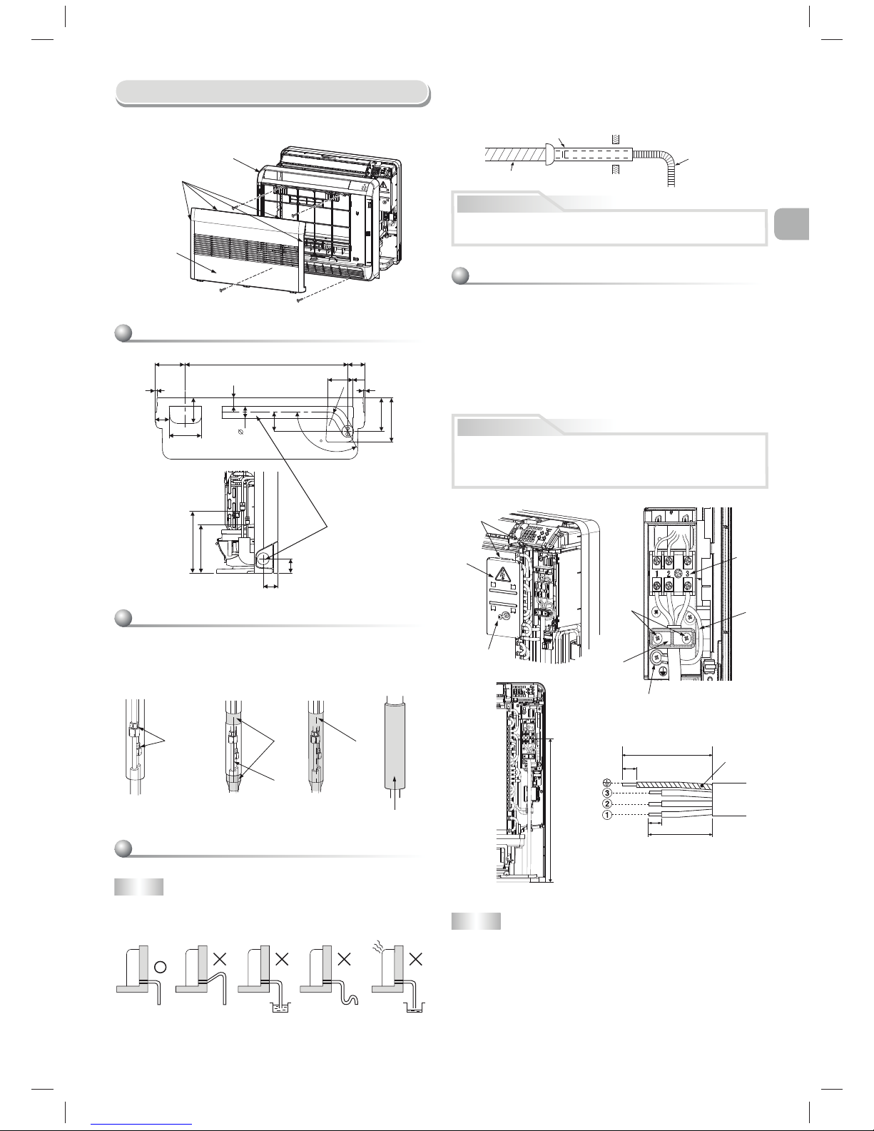
1. Remove the air inlet grille. Open the air inlet grille and remove the strap.
2. Remove the front panel (Remove the 4 screws).
NOTE
• The hole should be made at a slight downward slant on the outdoor side.
Shield pipe
Drain hose
Extension drain hose
Inside the room
2. Put water in the drain pan and make sure that the water is drained out of
doors.
3. When connecting extension drain hose, insulate the connecting part of
extension drain hose with shield pipe.
CAUTION
Arrange the drain pipe for proper drainage from the unit.
Improper drainage can result in dew-dropping.
Front panel
Air inlet grille
Hook
Treatment of piping connection
1) Check the fl are nut connections for the gas leak with a gas leak detector
or soap water.
2) To prevent gap in slit, fasten top and bottom with tape.
3) Slit is covered with tape.
4) Fasten with supplied Insulate sheet to prevent gap on the top of slit.
Gas leak check
Tape
Slit
9 Insulation sheet
Do not rise the
drain hose.
Do not form the
drain hose into
a wavy shape.
Do not put the
drain hose end
into water.
Do not put the
drain hose end in
the drainage ditch.
Drainage
1. Run the drain hose sloped downwards.
Wiring connection
Wiring of the connection cable is necessary to remove the front panel.
1. Remove the terminal cover and cord clamp.
2. Insert the connecting cable (according to the local rule) into the pipe hole
on the wall.
3. Take out the connecting cable through the cable slot on the rear panel so
that it protrudes about 50 cm from the front.
4. Insert the connecting cable fully into the terminal block and secure it
tightly with screws.
5. Tightening torque : 1.2 N·m (0.12 kgf·m)
6. Secure the connecting cable with the cord clamp.
7. Fix the terminal cover, install the front panel and grille inlet.
CAUTION
• Be sure to refer to the wiring system diagram labeled inside the front
panel.
• Check local electrical cords and also any specifi c wiring instructions or
limitations.
110 mm
20 mm
10 mm
50 mm
NOTE
• Use stranded wire only.
• Wire type : H07RN-F or 60245 IEC66 (1.0 mm
2
or more)
Stripping length of the connecting cable
Terminal
block
Earth line
Screw
Cord clamp
Earth screw
Earth line
Screw
Terminal cover
Hook
Layout of connection piping
Connection piping
430 mm
Tape
EN
SV
FI
NO
5
(700)
(600)
272
560
670
240 340
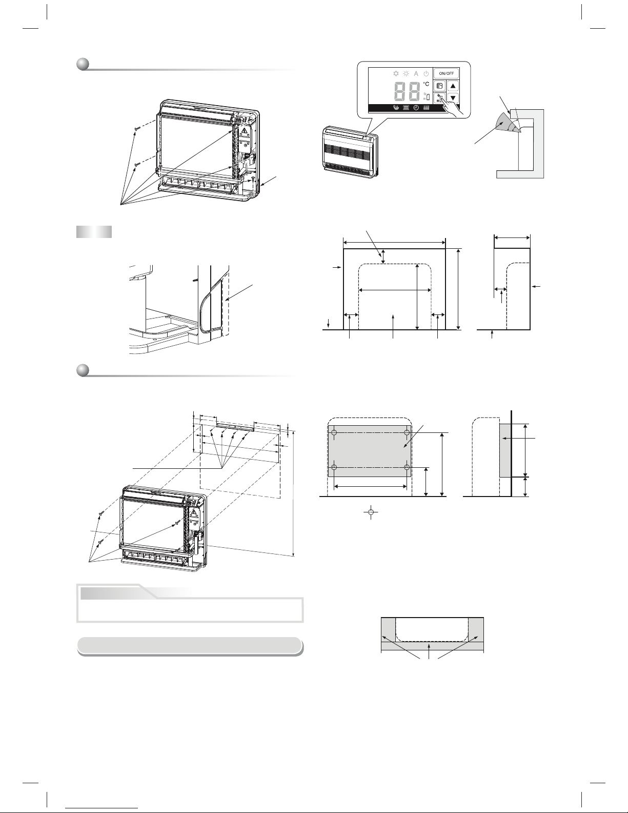
Concealed Installation
The special method to install the indoor unit bury in the wall is shown here.
Please make sure to change to wall burying mode.
1. To switch to the wall burying mode
To switch to the wall burying mode, press and hold AIR OUTLET
SELECT button for 20 seconds.
- When the operation set up and 5 beep sounds. Then indication at
Temperature indicator will light up for 5 seconds.
- To cancel, press AIR OUTLET SELECT button for 20 seconds then, 5
beep sounds. Then indication at Temperature indicator will blinks for 5
seconds.
- To prevent dewfall, above plate angle should be narrow.
3. Installation using the supporting plate
• To install into the existing wall hole, if it is impossible to keep 20-30 mm
of depth, use the supporting plate for securing the distance.
• Arrange the screw positions and supporting plate as shown in the
fi gure.
• Be sure to switch to wall burying mode.
(Rear screws potion)
(Field supply)
: Screw holes
(Field supply)
(Unit : mm)
Wall burying mode
For prevent dewfall
2. Wall hole size
Wall hole size should be enough to keep the distance with indoor unit as
shown in the following fi gure.
50 or more Indoor unit 50 or more
(Front view)
70 or more
800 or more
Wall
Floor
670 or more
2
0 to 30
240 to 250
Floor
Wall
(Side view)(Unit : mm)
4. In case of lattice establishment
• Follow the following fi gure, make sure to keep enough distance
between lattice, frame and wall.
• Be sure to switch to wall burying mode.
• The lattice should be make of wood.
• Between the air inlet and outlet, should be devided with partition board.
• Be sure to establish the open part for RECEIVER.
• The open part of lattice must be opens 70 % or more of the wall hole.
• The open part of lattice must be arranged uniformly.
(Top view)
Partition board
(Unit : mm)
(Side view)
NOTE
• In case the plinth is fi xed to the wall, please make sure to cut out the slit
on the left and right side of the main part.
Mounting directly on the fl oor.
1) Fix the leg of indoor unit on the fl oor with 2 mounting screws.
2) Fix the upper part of indoor unit on the wall with 4 mounting screws.
Cut dot-line area
Slit
6 screw
(M4 x 25L)
Installation on the wall
1) Fix the installation plate on the wall with 4 mounting screws.
2) Hook the indoor unit on the installation plate.
3) Fix the upper part of indoor unit on the wall with 4 mounting screws.
(Floor installation)
CAUTION
Make sure to fi x it at a designated position with the screws.
Failure may result the damage of piping by the turning over of a set.
(Wall installation)
1000 mm or less
4 screw
(M4 x 25L)
4 screw
(M4 x 25L)
6
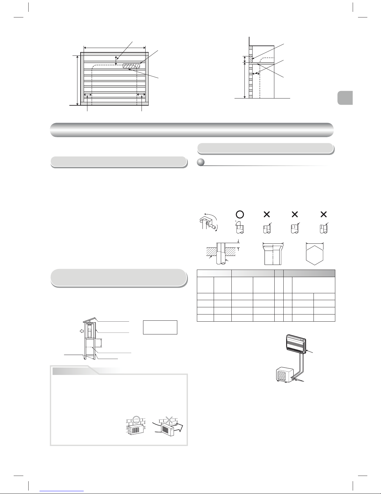
A
BC
500 140
(Side view)
Partition board
20 to 30
Opening for receiver
(Front view)
800 or more
670 or more
Partition board
Opening for receiver
50 or more
50 or more
70 or more
OUTDOOR UNIT
OUTDOOR UNIT
Installation Place
• A place which provides enough spaces around the outdoor unit as shown
in the diagram.
• A place which can bear the weight of the outdoor unit and does not allow
an increase in noise level and vibration.
• A place where the operation noise and discharged air do not disturb your
neighbors.
• A place which is not exposed to a strong wind.
• A place free of a leakage of combustible gases.
• A place which does not block a passage.
• When the outdoor unit is to be installed in an elevated position, be sure to
secure its feet.
• An allowable length of the connecting pipe is up to 25 m.
• There is no need to add refrigerant as long as the length of the
connection piping is 15 m or less.
• You will need to add 20 g of refrigerant per meter of added connection
piping for installation requiring connection piping to be between 16 m to
25 m.
• An allowable height level is up to 10 m.
• A place where the drain water does not cause any problems.
CAUTION
1. Install the outdoor unit in a location where there are no obstructions
near its air intake or air outlet.
2. When the outdoor unit is installed in a place that is always exposed to
strong winds like on the coast or on a high story of a building, secure
the normal fan operation using a duct or a wind shield.
3. Especially in windy areas, install the unit to prevent the admission of
wind.
4. Installation in the following places may result in trouble.
Do not install the unit in such places.
• A place full of machine oil.
• A saline-place such as the coast.
• A place full of sulfi de gas.
• A place where high-frequency
waves are likely to be generated,
such as from audio equipment, welders, and medical equipment.
Strong
wind
Snow protection plate
Snow protection hood
At least 50 cm
Snow accumulation line
Holding frame
Front
Anchor bolts
Install at least 50 cm
above the snow
accumulation line.
• Do not use the supplied drain nipple for draining water. Drain the water from
all the drain holes directly.
• To protect the outdoor unit from snow accumulation, install a holding frame,
and attach a snow protection hood and plate.
* Do not use a double-stacked design.
Precautions about Installation in Regions
with Snowfall and Cold Temperatures
• When using a multi-system outdoor unit refer to the installation manual
provided with the model concerned.
Refrigerant Piping Connection
Flaring
1. Cut the pipe with a pipe cutter.
2. Deburr the inside of the pipe at its end.
Take steps to ensure that the removed burrs will not enter the pipe.
3. Remove the fl are nuts provided with the indoor and outdoor units, and
insert them into the pipe.
4. Flare the pipe.
The projection margin of the pipe must be checked.
5. Check that the fl are has the appropriate shape.
90
Obliquity Roughness Warp
Pipe
Die
Pipe A B Flare Nut
Outside
diameter
Thickness
Rigid
(clutch type)
R410A tool
Imperial
(wing nut
type)
R410A tool
C Tighten torque
mm mm mm mm mm mm N·m kgf·m
6.35 0.8 0 to 0.5 1.5 to 2.0 9.1 17 14 to 18 1.4 to 1.8
9.52 0.8 0 to 0.5 1.5 to 2.0 13.2 22 33 to 42 3.3 to 4.2
12.7 0.8 0 to 0.5 2.0 to 2.5 16.6 26 50 to 62 5.0 to 6.2
• Tightening torque for connection of fl are pipe
The pressure of R410A is higher than R22
(Approx. 1.6 times). Therefore securely
tighten the fl are pipes which connect the
outdoor unit and the indoor unit with the
specifi ed tightening torque using a torque
wrench. If any fl are pipe is incorrectly
connected, it may cause not only
a gas leakage but also trouble in the
refrigeration cycle.
Flare at
indoor unit side
Flare at
outdoor unit side
EN
SV
FI
NO
7
10
30
30
40
40
10
10
10
L
N
1
2
3
Model RAS-25UFV-ND RAS-35UFV-ND
Power source
220–240V ~ 50Hz
220–230V ~ 60Hz
220–240V ~ 50Hz
220–230V ~ 60Hz
Maximum running
current
7.8A 8.8A
Plug socket & fuse
rating
10A 11A
Power cord H07RN-F or 60245 IEC66 (1.5 mm
2
or more)
Connecting cable H07RN-F or 60245 IEC66 (1.0 mm
2
or more)
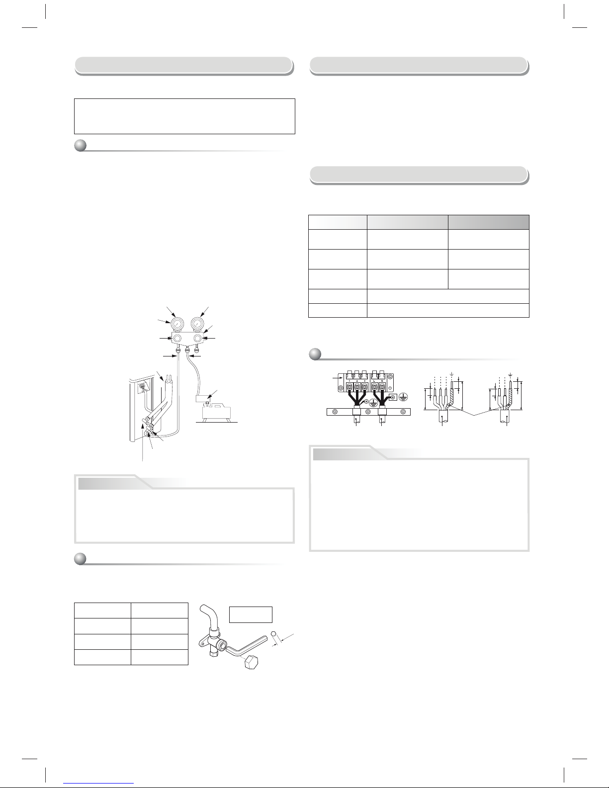
Wiring Connection
1. Remove the valve cover, the electric parts cover and the cord clamp from
the outdoor unit.
2. Connect the connecting cable to the terminal as identifi ed by the matching
numbers on the terminal block of indoor and outdoor unit.
3. Insert the power cord and the connecting cable fully into the terminal
block and secure it tightly with screws.
4. Use vinyl tape, etc. to insulate the cords which are not going to be used.
Locate them so that they do not touch any electrical or metal parts.
5. Secure the power cord and the connecting cable with the cord clamp.
6. Attach the electric parts cover and the valve cover on the outdoor unit.
Electrical Work
1. The supply voltage must be the same as the rated voltage of the air
conditioner.
2. Prepare the power source for exclusive use with the air conditioner.
Packed valve handling precautions
• Open the valve stem until it touches the stopper. Once it is in contact with
the stopper, refrain from applying any more force than is necessary.
• Securely tighten the valve stem cap with torque in the following table:
Evacuating
After the piping has been connected to the indoor unit, you can perform
vacuuming together at once.
Using a vacuum pump
Be sure to use a vacuum pump with counter-fl ow prevention function so
that inside oil of the pump does not fl ow backward into pipes of the air
conditioner when the pump stops.
(If oil inside of the vacuum pump enters the air conditioner, which use
R410A, refrigeration cycle trouble may happen.)
1. Connect the charge hose from the manifold valve to the service port of the
packed valve at gas side.
2. Connect the charge hose to the port of the vacuum pump.
3. Open fully the low pressure side handle of the gauge manifold valve.
4. Operate the vacuum pump to start evacuating. Perform evacuating for
about 15 minutes if the piping length is 20 meters
(15 minutes for 20
meters) (assuming a pump capacity of 27 liters per minute). Then confi rm
that the compound pressure gauge reading is –101 kPa (–76 cmHg).
5. Close the low pressure side valve handle of the gauge manifold valve.
6. Open fully the valve stem of the packed valves (both gas and liquid
sides).
7. Remove the charging hose from the service port.
8. Securely tighten the caps on the packed valves.
VACUUMING
Evacuate the air in the connecting pipes and in the indoor unit using a
vacuum pump. Do not use the refrigerant in the outdoor unit. For details,
see the manual of the vacuum pump.
Pressure gauge
Manifold valve
–101 kPa (–76 cmHg)
Handle Lo
Connecting pipe
Compound pressure gauge
Vacuum
pump
Handle Hi
(Keep full closed)
Charge hose
(For R410A only)
Vacuum pump adapter for
counter-fl ow prevention
(For R410A only)
Service port (Valve core (Setting pin))
Packed valve at liquid side
Packed valve at gas side
Charge hose
(For R410A only)
Hexagon wrench
is required.
Gas side
(∅12.70 mm)
50 to 62 N·m
(5.0 to 6.2 kgf·m)
Gas side
(∅9.52 mm)
33 to 42 N·m
(3.3 to 4.2 kgf·m)
Liquid side
(∅6.35 mm)
14 to 18 N·m
(1.4 to 1.8 kgf·m)
Service port
14 to 18 N·m
(1.4 to 1.8 kgf·m)
4 mm
X When using a multi-system outdoor unit is used, refer to the installation
manual provided with the model concerned.
Stripping length of the connecting cable
Connecting cable Power cord Connecting cable Power cord
Terminal
block
Earth line
CAUTION
• Wrong wiring connection may cause some electrical parts burn out.
• Be sure to comply with local rule on running the wire from indoor unit
to outdoor unit (size of wire and wiring method, etc.).
• Every wire must be connected fi rmly.
• If incorrect or incomplete wiring is carried out, it will cause an ignition
or smoke.
• Prepare the power supply for exclusive use with the air conditioner.
• This product can be connected to the mains.
Connection to fi xed wiring : A switch which disconnects all poles and
has a contact separation of at least 3 mm must be incorporated in the
fi xed wiring.
CAUTION
• KEEP IMPORTANT 5 POINTS FOR PIPING WORK.
(1) Take away dust and moisture (inside of the connecting pipes).
(2) Tighten the connections (between pipes and unit).
(3) Evacuate the air in the connecting pipes using a VACUUM PUMP.
(4) Check gas leak (connected points).
(5) Be sure to fully open the packed valves before operation.
8
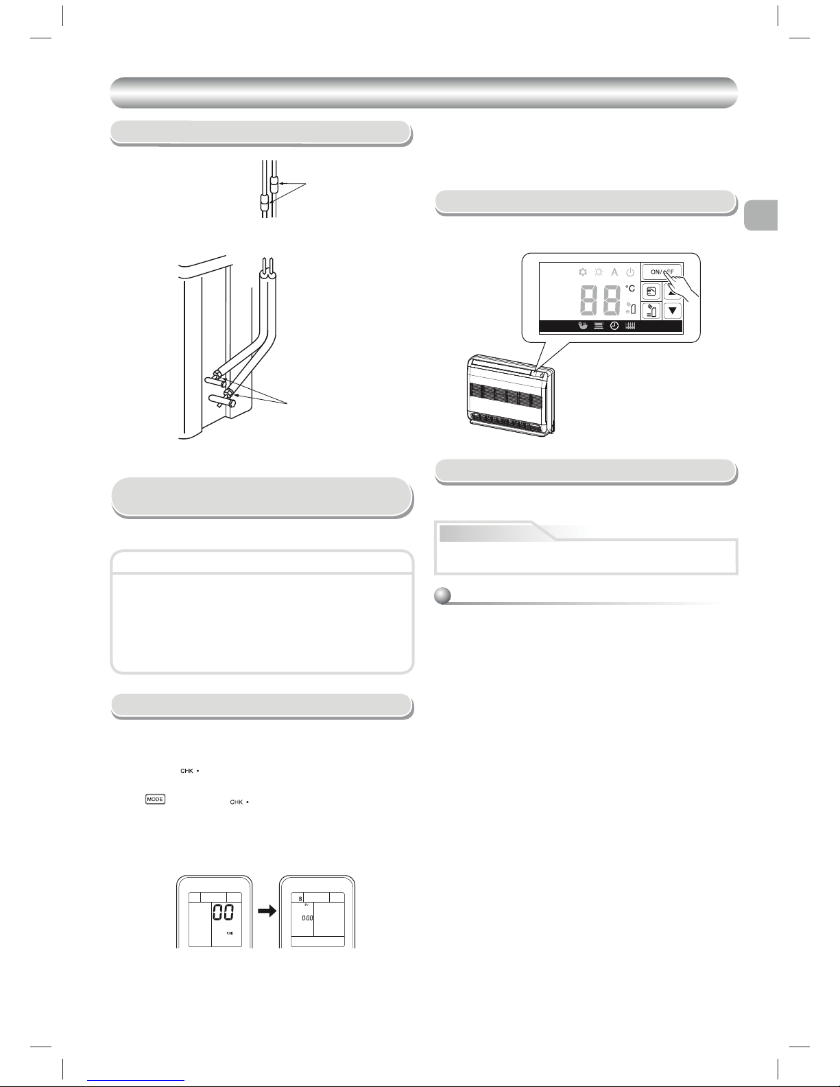
• Check the fl are nut connections for the gas leak with a gas leak detector
or soap water.
Gas Leak Test
Check places for
the indoor unit.
Check places for
the outdoor unit.
Remote control selector switch
• When two indoor units are installed in the same room or adjacent two
rooms, if operating a unit, two units may receive the remote control
signal simultaneously and operate. In this case, the operation can
be preserved by setting either one indoor unit or remote control to B
setting (Both are set to A setting in factory shipment).
• The remote control signal is not received when the settings of indoor
unit and remote control are different.
• There is no relation between A setting/B setting and A room/B room
when connecting the piping and cables.
When two indoor units are installed in the separated rooms, it is not
necessary to change the selector switches.
Setting of Remote Control
Selector Switch
Remote Control A-B Selection
To separate using of remote control for each indoor unit in case of 2 air
conditioners are installed nearly.
Remote Control B Setup.
1. Push and hold
button on the Remote Control by the tip of the pencil.
“00” will be shown on the display.
2. Press
during pushing . “B” will show on the display and “00”
will disappear and the air conditioner will turn OFF. The Remote Control B
is memorized.
Note : 1. Repeat above step to reset Remote Control to be A.
2. Remote Control A has not “A” display.
3. Default setting of Remote Control from factory is A.
Unit B setup.
Press and hold MODE button for more than 20 seconds.
When A setup changed to B setup : 5 beeps will sound and operation
lamp blinks for 5 seconds.
When B setup changed to A setup : 5 beep will sound.
OTHERS
OTHERS
Test Operation
Auto Restart Setting
How to set the Auto Restart
1.
Press and hold
OPERATION
button on the indoor unit for 3 seconds to set
the operation (3 beep sound and OPERATION lamp blink 5 time/sec for 5
seconds).
2. Press and hold
OPERATION
button on the indoor unit for 3 seconds to
cancel the operation (3 beep sound but OPERATION lamp does not blink).
•
In case of ON timer or OFF timer are set, it dose not activate.
This product is designed so that, after a power failure, it can restart
automatically in the same operating mode as before the power failure.
To switch the TEST RUN (COOL) mode, press OPERATION button for 10
seconds (The beeper will make a short beep).
Information
The product are shipped with Auto Restart function in the off position.
Turn it on as required.
EN
SV
FI
NO
9
SÄKERHETSANVISNINGAR
SÄKERHETSANVISNINGAR
Läs den här installationshandboken noga före installation.
Användaren rekommenderas att utföra underhåll regelbundet för lång användning.
Var noggrann med att följa dessa medföljande säkerhetsföreskrifter för att undvika säkerhetsrisker. Symbolerna och deras betydelse visas nedan.
FARA
: Detta betyder att felaktig användning av enheten kan innebära stor risk för allvarlig skada (*1) eller dödsfall.
VARNING
: Det indikerar att oriktig användning av denna enhet kan orsaka allvarlig skada eller dödsfall.
VAR FÖRSIKTIG : Det indikerar att oriktig användning av denna enhet kan orsaka personskada (*2), eller skada på egendom (*3).
*1: Med allvarlig skada avses blindhet, kroppsliga men, brännskador eller köldskador, elstötar, benbrott eller förgiftning med
efterverkningar och läkarvård eller långvarig poliklinisk behandling.
*2: Personskada innebär en mindre olycka, brännskada, eller elstöt som inte kräver åtgärd eller upprepad sjukhusbehandling.
*3: Skada på egendom innebär större skada som påverkar egendom eller tillgångar.
Avsedd för allmän användning
Nätsladden för utomhusbruk ska minst vara av typen neoprenmantlad böjlig kabel (utförande H07RN-F), eller av typen 60245 IEC66 (av minst 1,5 mm2
eller tjockare) (Ska installeras enligt nationella föreskrifter om elinstallationer).
Installation av luftkonditionering med nytt kylmedel
VAR FÖRSIKTIG
• LUFTKONDITIONERINGSAGGREGATET ANVÄNDER HFC-KÖLDMEDIET (R410A) SOM INTE FÖRSTÖR OZONLAGRET.
Köldmediet R410A har benägenheten att lätt bli förorenat av vatten, oxiderande membran och oljor eftersom R410A har ett tryck som är ungefär 1,6
gånger så högt som för R22. Förutom att ett nytt köldmedium används, så har även kyloljan i aggregatet bytts. Därför är det viktigt att se till att inget
vatten, damm, äldre sorters köldmedium eller maskinkylolja kommer in i kylkretsen på luftkonditioneringsaggregat som använder denna nya typ av
köldmedium. För att undvika att köldmedium och maskinkylolja blandas, så är huvudenhetens påfyllningsportar och anslutningsdelar av en annan
storlek än de för konventionellt köldmedium, och det krävs också verktyg av andra storlekar. Till förbindelserör ska endast nya och rena rörledningar
som enbart är avsedda för R410A och tål högt tryck användas. Se till att vatten eller damm inte kommer in i ledningarna. Befintliga rörledningar kan
vara förorenade, och kanske inte klarar av det höga trycket. De ska därför inte användas.
FARA
• FÅR ENDAST ANVÄNDAS AV BEHÖRIGA PERSONER.
• I DEN FASTA KABELDRAGNINGEN MÅSTE ALLA POLER KUNNA KOPPLAS BORT FRÅN NÄTSTRÖMMEN MED ETT AVSTÅND PÅ MINST 3 mm
MELLAN POLERNA.
• KOPPLA ALLTID UR AGGREGATET FRÅN NÄTSTRÖM FÖRE ELARBETEN. FÖRSÄKRA DIG OM ATT ALLA STRÖMBRYTARE ÄR
FRÅNKOPPLADE. OM INTE, FINNS RISK FÖR ELEKTRISKA STÖTAR.
• SE TILL ATT ANSLUTNINGSKABELN ANSLUTS KORREKT. OM ANSLUTNINGSKABELN ANSLUTS PÅ FELAKTIGT SÄTT KAN SKADOR UPPSTÅ
PÅ DELARNA I ELSYSTEMET.
• KONTROLLERA FÖRE INSTALLATIONEN ATT JORDLEDAREN INTE ÄR TRASIG ELLER FRÅNKOPPLAD.
• FÅR INTE INSTALLERAS I NÄRHETEN AV GASBEHÅLLARE, ANTÄNDLIG GAS ELLER DÄR DET FINNS RISK FÖR GASLÄCKOR. ATT INTE
FÖLJA DENNA ANVISNING KAN ORSAKA ELDSVÅDA ELLER EXPLOSION.
• UNDVIK RISK FÖR ÖVERHETTNING OCH BRANDFARA GENOM ATT PLACERA INOMHUSENHETEN PÅ MINST 2 METERS AVSTÅND FRÅN
VÄRMEKÄLLOR SOM ELEMENT, VÄRMEAGGREGAT, VÄRMEPANNOR, UGNAR, SPISAR OCH LIKNANDE.
• VAR FÖRSIKTIG SÅ ATT INTE KÖLDMEDIET R410A ELLER ANNAN GAS KOMMER IN I KYLKRETSEN DÅ LUFTKONDITIONERINGEN
SKA FLYTTAS FÖR ATT INSTALLERAS PÅ ANNAN PLATS. OM LUFT ELLER ANNAN GAS BLANDAS MED KÖLDMEDIET BLIR TRYCKET I
KYLKRETSEN ONORMALT HÖGT, VILKET KAN GÖRA ATT RÖREN SPRÄNGS OCH PERSONSKADOR UPPSTÅR.
• VÄDRA OMEDELBART I LOKALEN MED FRISK LUFT OM KÖLDMEDIEGAS SKULLE LÄCKA UT UNDER INSTALLATIONEN. OM KÖLDMEDIEGAS
HETTAS UPP AV ELD ELLER ANNAN VÄRMEKÄLLA UTVECKLAS EN GIFTIG GAS.
• NÄR LUFTKONDITIONERINGEN INSTALLERAS ELLER ÅTERINSTALLERAS FÅR INTE LUFT ELLER ANDRA ÄMNEN FÖRUTOM DET AVSEDDA
KYLMEDEL ”R410A” INJICERAS I KYLSYSTEMET. OM LUFT ELLER ANDRA ÄMNEN BLANDAS KAN DET HÄNDA ATT ETT ONORMALT TRYCK
UPPSTÅR I KYLSYSTEMET VILKET KAN LEDA TILL SKADA PÅ GRUND AV ATT RÖRET BRISTER.
1
 Loading...