

toshiba 3560, 3570 Service Manual

SERVICE MANUAL
PLAIN PAPER COPIER
Click the Page Only button to close the overview area of the window.
Click the Bookmarks and Page button to open the Contents and
3560/70
display bookmarks created for the document. Click a bookmark’s name
to go to the Page marked by that bookmark.
Click the Thumbnails and Page button to open the overview area and
display thumbnail images of each document page. Click a thumbnail to
go to the page marked by that thumbnail.
Copyright TOSHIBA CORPORATION 1995
ALL RIGHTS RESERVED
GENERAL PRECAUTIONS REGARDING THE INSTALLATION
AND SERVICE FOR THE COPIER 3560/70
The installation and service should be done by a qualified service technician.
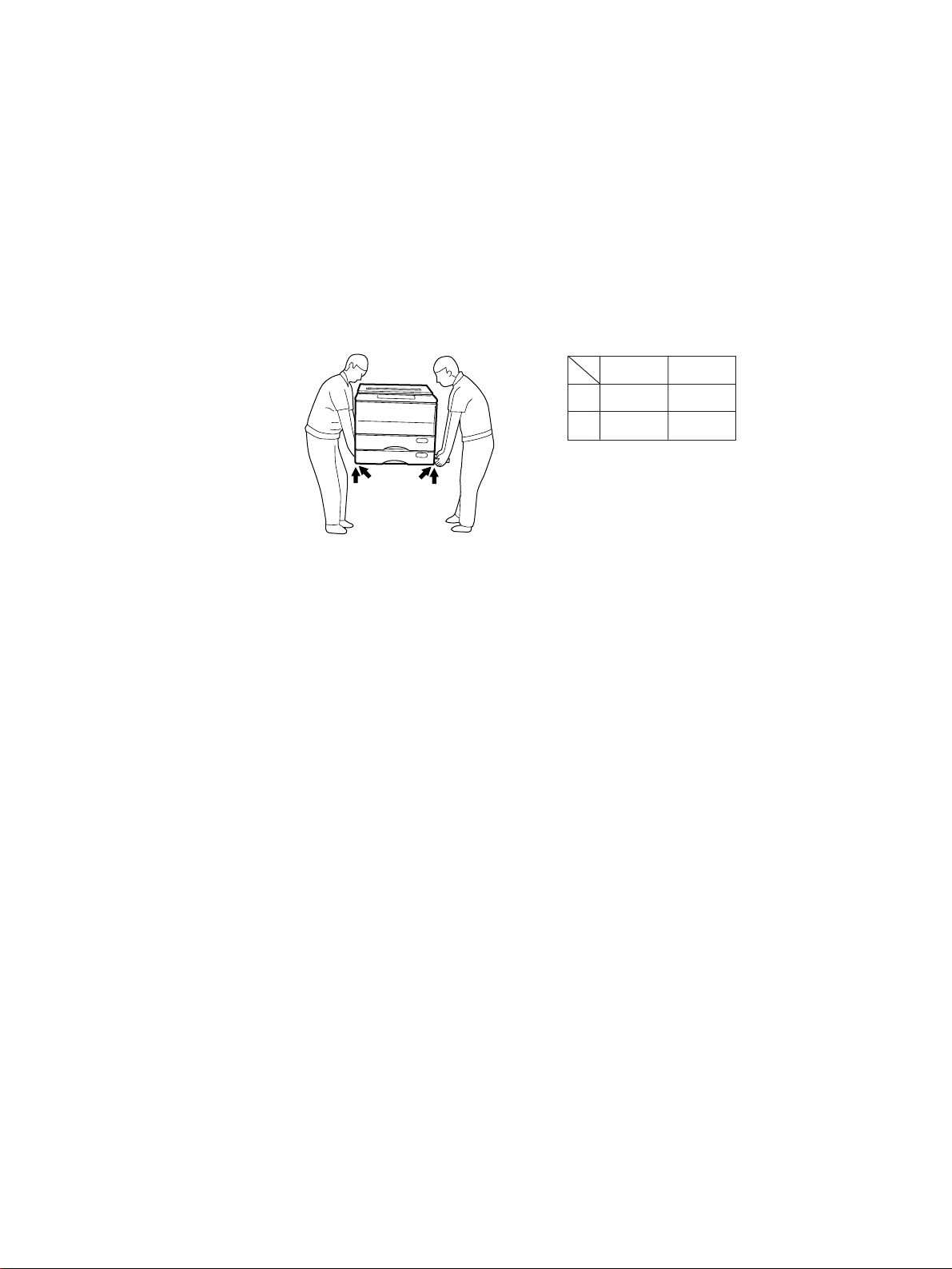
1. Transportation/Installation
• When transporting/installing the copier, use two persons and be sure to use the positions as indicated below.
The copier is fairly heavy and weighs approximately A kg (B lb), therefore pay full attention when
handling it.
3560
3570
4 portions
73
A
161
B
92
203
2. Installation
• Be sure to use a dedicated outlet with AC 115V/15A (220V, 230V , 240V/10A) or more for its power
source.
• The copier must be grounded for safety.
Never ground it to a gas pipe or a water pipe.
• Select a suitable place for installation.
Avoid excessive heat, high humidity, dust, vibration and direct sunlight.
• Also provide proper ventilation as the copier emits a slight amount of ozone.
• To insure adequate working space for the copying operation, keep a minimum clearance of 80 cm
(32”) on the left, 80 cm (32”) on the right and 10 cm (4”) in the rear.
• After having installed the copier, be sure to push the carrying handles into the copier and fasten
them with screws.
3. Service of Machines
• Basically, be sure to turn the main switch off and unplug the power cord during service.
• Be sure not to touch high-temperature sections such as the exposure lamp, the fuser unit, the
damp heater and their periphery.
• Be sure not to touch high-voltage sections such as the chargers and the high-voltage transformer.
• Be sure not to touch rotating/operating sections such as gears, belts, pulleys, etc.
• When servicing the machines with the main switch turned on, be sure not to touch live sections
such as the lamp terminal, etc. and rotating/operating sections.
• Use suitable measuring instruments and tools.

4. Main Service Parts for Safety
• The breaker, door switch, fuse, thermostat, thermofuse, thermistor, etc. are particularly important
for safety. Be sure to handle/install them properly.
5. Cautionary Labels
• During service be sure to check the rating plate and the cautionary labels such as “Unplug the
power cord during service”, “Hot area” etc. to see if there is any dirt on their surface or whether
they are properly stuck to the copier.
6. Disposition of Consumable Parts/Packing Materials
• Regarding the recovery and disposal of the copier, supplies, consumable parts and packing materials, it is recommended to follow the relevant local regulations or rules.
7. When parts are disassembled, reassembly is basically the reverse of disassembly unless
otherwise noted in this manual or other related documents. Be careful not to reassemble
small parts such as screws, washers, pins, E-rings, toothed washers in the wrong places.
8. Basically, the machine should not be operated with any parts removed or disassembled.
9. Precautions Against Static Electricity
• The PC board must be stored in an anti-electrostatic bag and handled carefully using a wristband,
because the ICs on it may become damaged due to static electricity.
Caution:Before using the wrist band, pull out the power cord plug of the copier and make sure
that there is no uninsulated charged objects in the vicinity.
1. SPECIFICATIONS • ACCESSORIES • OPTIONS • SUPPLIES
1.1 Specifications
Copy process Indirect electrophotographic process (dry)
Type Desk top (console when the pedestal is used)
Exposure Type Slit exposure with fixed table
Acceptable originals Kind Sheets, books, and 3-dimensional objects.
When the document feeder is used:
Sheet originals only (60 g/m2~90 g/m2) (16 lb.~24 lb.)
Maximum size A3 (Ledger)
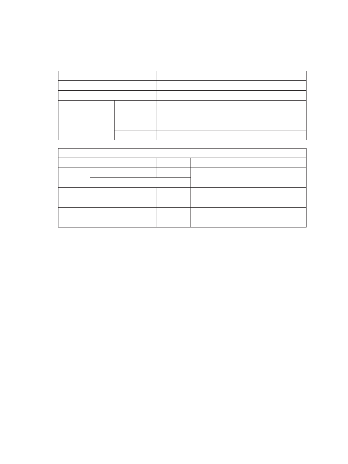
Copy paper
Cassette Duplexing Manual Note
Size A3~A5-R A3~A6-R Adjustable to
(Ledger~Statement-R) Unfixed, Arbitary sizes
Thickness 64~80 64~130 Unit: g/m
(Weight) (17~22) (17~34) (Unit: lb.)
2
Special _ _ OHP film
paper etc.
Nov. 1997 © TOSHIBA 1 - 1 3560/70 SPECIFICATIONS
Copy speed
System copy speed
Cassette/manual LCF
Paper size 3560 3570 3560 3570
A4, B5, A5-R 35 35 35 35
LT, ST-R
A4-R, B5-R 26 26 — —
LT-R
B4, FOLIO 22 22 — —
LG, Computer
A3 19 19 — —
LD
Reduction/ 15 15 15 15
Enlargement
Manual feeding represents the value when the size is set.
CPM
(BLI format)
Mode CPM
Original→Copy Number of copies 3560/70
1 → 1 1 set 30
3 set 33
5 set 34
1 → 2 1 set 10
3 set 19
5 set 24
2 → 2 1 set 8
3 set 17
5 set 21
2 → 1 1 set 16
3 set 25
5 set 29
*Ten originals (A4) are set in the RADF. This in-
cludes the first copy time.
First copy Approx. 4.0 sec. (Actual-size A4 or Letter from large capacity feeder)
Warm-up time Approx. 80 sec.
Multiple copying 1~999, keyboard entry
Reproduction ratio
Actual ratio 100% or 101% (Setting mode)
Zoom ratios 50~200% (Multiple reduction and enlargement in 1% steps)
3560/70 SPECIFICATIONS 1 - 2 Nov. 1997 © TOSHIBA
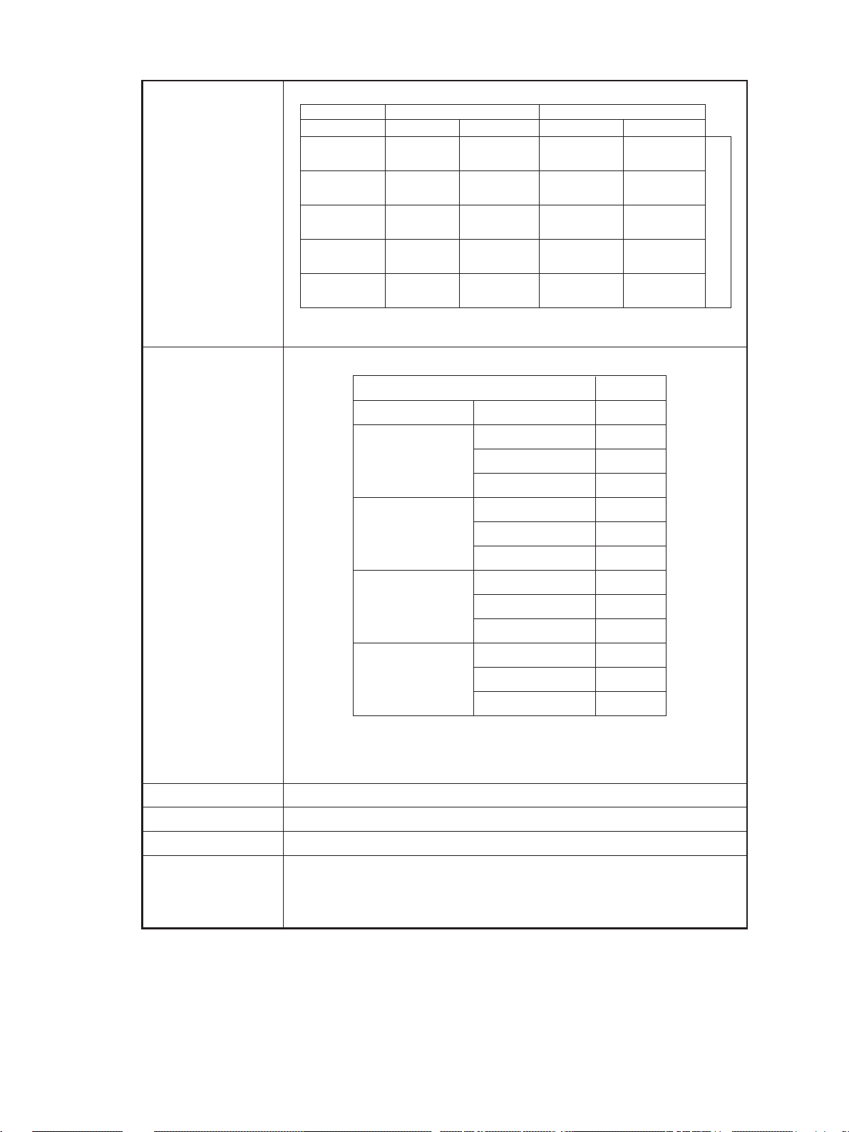
Paper supply Cassette or sheet-bypass feeding
Cassette: 600 sheets
Sheet-bypass feeding: 50 sheets
Toner supply Automatic density detection and replenishment
Toner cartridge replacement
Exposure Automatic control and manually selectable (9 steps)
*1
Weight Copier:
*1: 3560, *2: 3570 ADU: 10 kg
Power source 115 V ~ 60 Hz, 12A For the U.S.A. and Canada
220–240 V ~ 50/60 Hz, 8A For Europe
Power consumption 1.5 kW (115 V), 1.7 kW (220 V/240 V)
Counter 7-digit total counter
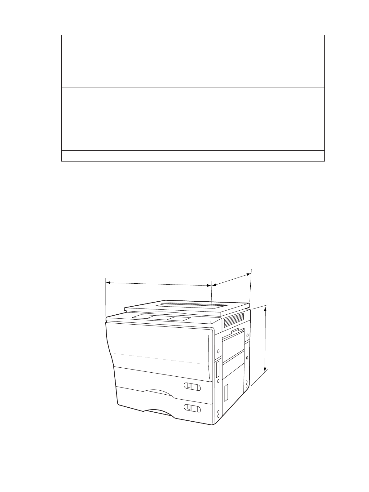
73 or *292 kg (with 2 cassettes and the platen cover),
Machine size
601mm
598mm
640mm
661mm
540mm
540mm
Nov. 1997 © TOSHIBA 1 - 3 3560/70 SPECIFICATIONS
1.2 Accessories
Copy receiving tray : 1 pc.
Operator’s manual : 1 pc.
Set-up report : 1 pc.
Drum : 1 pc.
Developer : 1 bottle
Toner : 1 pc.
*Accessories vary according to the destination.
1.3 Options
Automatic duplexing unit: ADU MD-5002A
Automatic document feeder: ADF MR-3006A (RADF), MR-2008 (ADF)
Paper feed pedestal: PFP KD-1003 (1 cassette), KD-2009 (2 cassettes)
Paper feed unit MY-1006
Large capacity feeder: LCF MP-1501LT, MP-1501A4, MP-4001LT, MP-4001A4
Sorter MG-1003B (10 bins), MG-2012 (20 bins)
Key copy counter MU-8/MU-10 (6 digit)
*Options vary according to the destination.
1.4 Supplies
Drum OD-3560
Developer ZD-3560
Toner ZT-3560, 3560E
MG-1004A (10 bins staple)
MG-2009A (20 bins)
MG-2010 (20 bins staple)
3560/70 SPECIFICATIONS 1 - 4 Nov. 1997 © TOSHIBA
2. OUTLINE OF THE MACHINE
2.1 Sectional Views and Electrical Parts Location Diagram
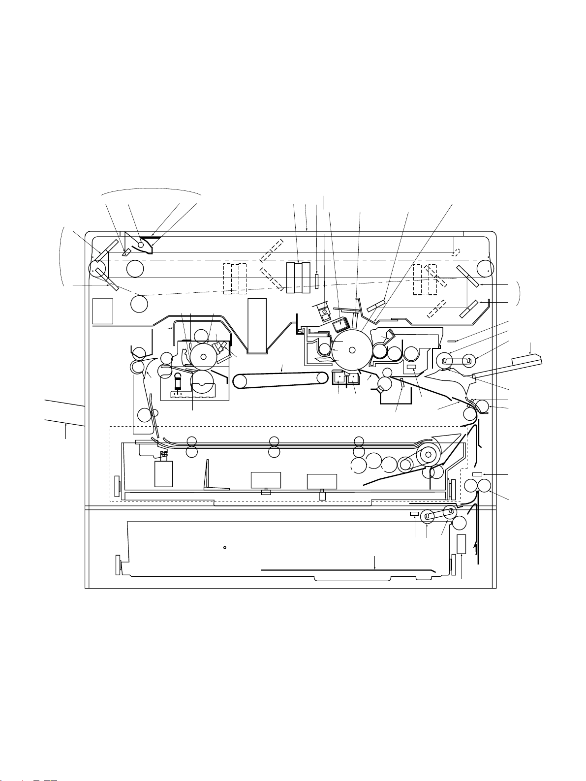
2.1.1 Sectional view
[A] Front view
1
2
5
7
6
8
AQ
FK
FR
ES
FR
ES
FQ
BT
4
EP ER
3
ENEM
GK
EL
EQ
EO
FT
GT
EK
AO
CT
AS
AP AN
AR BK AL
BL
BN
BM
BR
BO
BP
BQ
FS
AM
AT
9
AK
DO
CL
CK
CN
CO
DS
BS
ET
CM
DR
DP
CS
DT
CP
CR
FL
DN
DK
DL
CQ
FO
DMFN
FP
(This diagram includes an installed ADU.)
Nov. 1997 © TOSHIBA 2 - 1 3560/70 GENERAL
FM
DQ

No. Name
No. Name
1 Carriage 1
2 Mirror 1
3 Reflector
4 Light distribution adjustment plates
5 Exposure lamp
6 Carriage 2
7 Mirror 2
8 Mirror 3
9 Mirror unit
AT Mirror 4
AK Mirror 5
AL Mirror 6
AM Slit glass
AN Auto exposure sensor
AO Lens
AP Original glass
AQ Ozone filter
AR Main charger
CQ Cassette
CR Manual feed separation pad
CS Manual feed roller
DT Manual pickup roller
DK Cassette separation roller
DL Cassette feed roller
DM Cassette pickup roller
DN Upper transport roller
DO Manual feed switch (S6)
DP Paper guide
DQ Lower transport roller
DR Aligning switch (S8)
DS Aligning roller (U)
ET Aligning roller (L)
EK Thermistor-1 (THMS1)
EL Thermostat (THERMO)
EM Heater lamp
EN Heat roller (upper side)
AS Discharge lamp
BT Receiving tray
BK LED eraser array
BL Main blade
BM Recovery blade
BN Toner recovery auger
BO Separation claw (for drum)
BP Transfer charger
BQ Separation charger
BR Drum
BS Bias guide
CT Transport belt
CK Magnetic roller
CL Leveller (doctor)
CM Auto-toner sensor
CN Mixer 1
CO Mixer 2
CP Sheet bypass guide
EO Pressure roller (lower side)
EP Separation claw (for heat roller)
EQ Felt roller
ER Heat roller cleaning blade
ES Fuser exit roller
FT Scraper
FK Fuser cover
FL Paper stop switch-1 (S7)
FM Paper stop switch-2 (S16)
FN Paper-empty switch-2 (S14)
FO Cassette tray
FP Cassette size switch-2 (S15)
FQ Exit/ADU selection gate
FR Exit roller
FS ADU (option)
GT Exit fan (M7)
GK Bottom fan (M8)
3560/70 GENERAL 2 - 2 Nov. 1997 © TOSHIBA
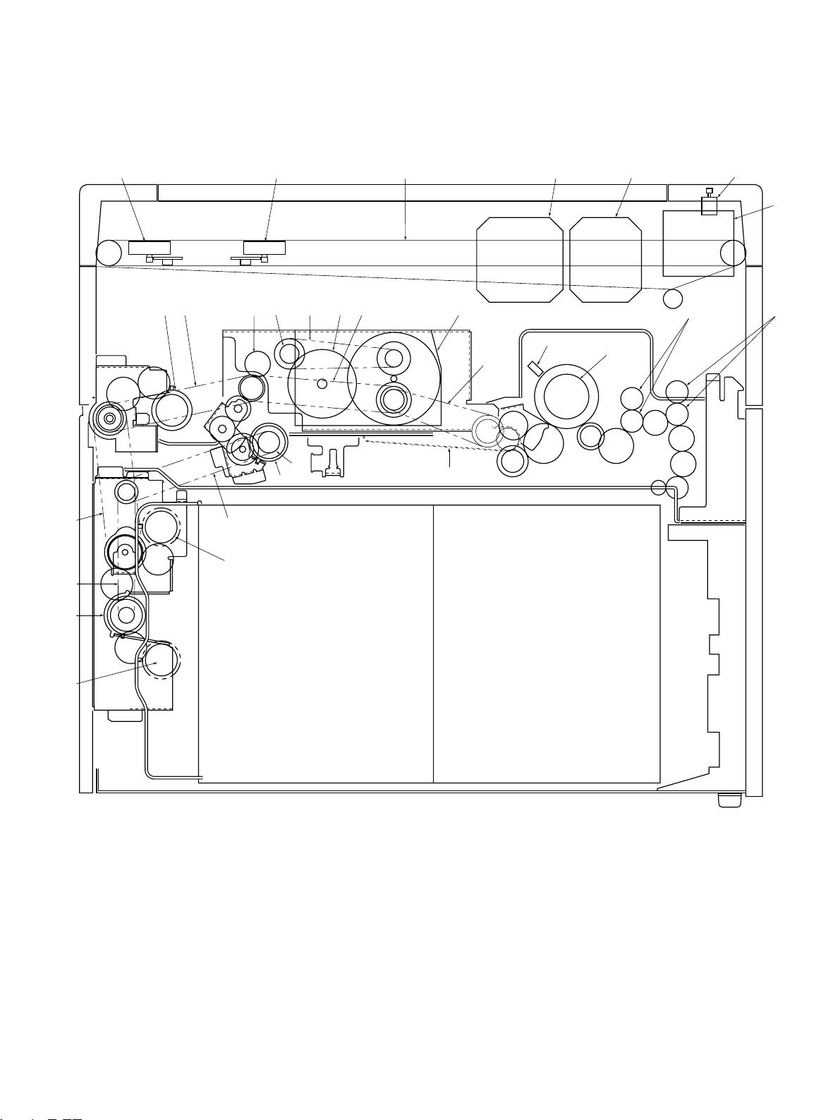
[B] Rear side view
HP HO IO IP
HLGRHKHTHRITIK
HS
GS
IT
IM
IT
IN
GQ IQ
HN
HQ
HM
CT
EN
GP
FRES
IL
IN
Nov. 1997 © TOSHIBA 2 - 3 3560/70 GENERAL

No. Name
GP Scanning motor (M2)
GQ Carriage drive wire
GR Drum gear
GS Aligning clutch (CL T2)
HT Drum driving gear
HK Drum belt
HL Belt for dev-unit, ALGN-roller & paper feeding drive
HM Belt for fuser drive
HN Main motor (M1)
HO Lens motor (M3)
HP Mirror motor (M4)
HQ Thermistor-2 (THMS2)
HR Dev-unit drive gear
HS Aligning roller
IT Paper feed belt
IK Manual feed clutch (CLT4)
IL Transport roller clutch (CLT1)
IM Transport roller drive belt
IN Cassette feed clutch (CLT3, 5)
IO Optical fan (M6,12)
IP Document motor (M11)
IQ Optical fan (M15)
3560/70 GENERAL 2 - 4 Nov. 1997 © TOSHIBA
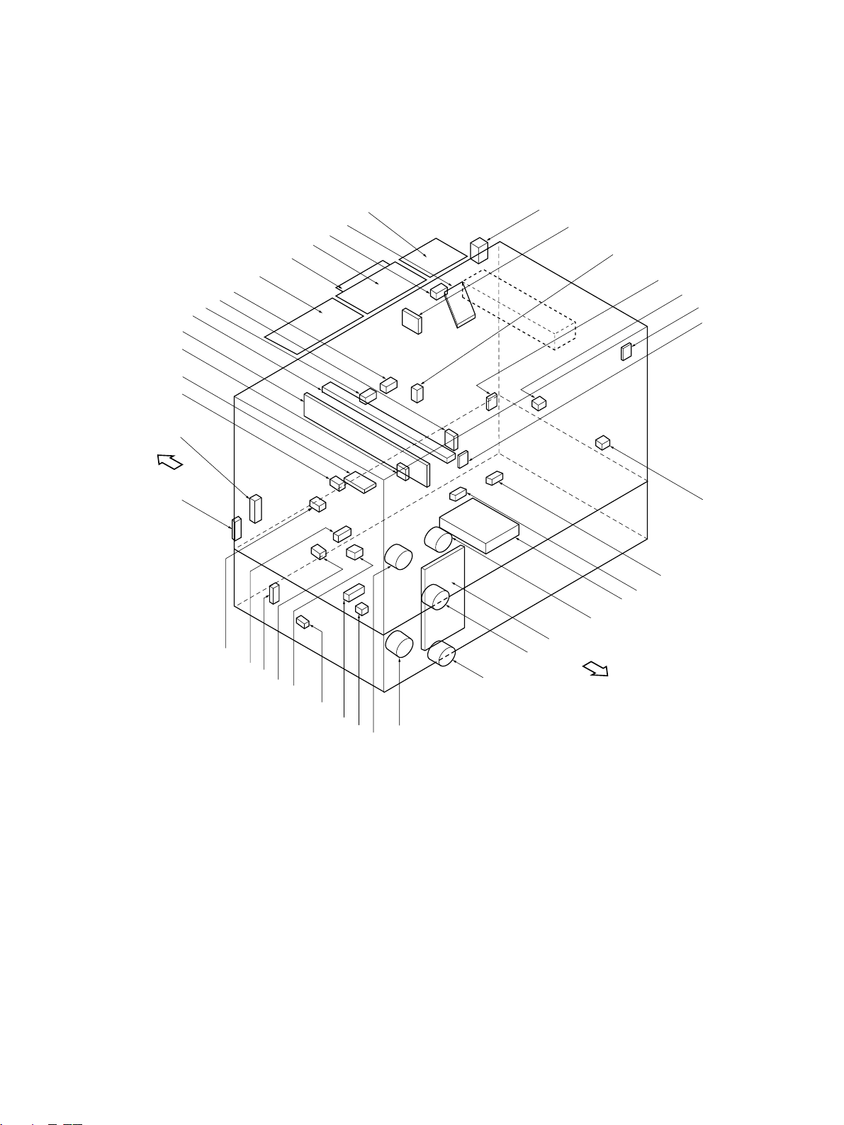
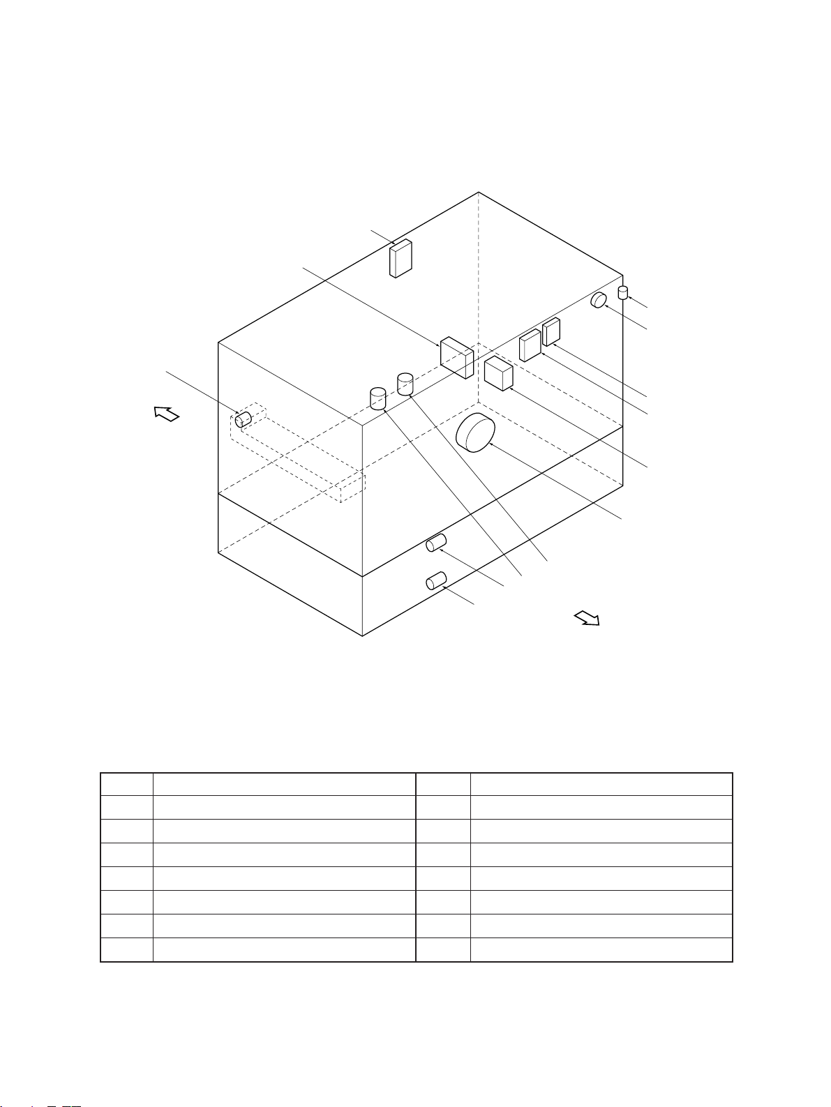
2.1.2 Electrical parts layout
[A] DC electrical parts (except motors)
[Front side]
AL
BP
BN
AQ
AT
AS
AK
8
BO
AP
7
BK
2
CM
AR
BR
CS
3
6
CP
BT
CO
DT
1
CK
CT
CN
CL
4
5
BQ
BS
DK
CR
AM
[Rear side]
BL
9
BM
AN
AO
CQ
Nov. 1997 © TOSHIBA 2 - 5 3560/70 GENERAL
No. Name
No. Name
1 Control panel key PC board (PWA-KEY2)
2 Control panel key PC board (PWA-KEY1)
3 Liquid crystal module (LCD)
4 Total counter (T-CTR)
5 Logic PC board (PWA-LGC)
6 Auto paper sensor-2 (APS-R)
7 Auto paper sensor-3 (APS-C)
8 Auto paper sensor-4 (APS-F)
9 Toner-full switch (T-FUL-SW) (S13)
*AT Size switch 1 (SIZE1-SW) (S5)
AK Discharge lamp PC board (PWA-ERS)
AL LED eraser array PC board (K-DCH)
AM High-voltage power supply (PS-HVT)
AN Home switch (HOME-SW) (S10)
AO Platen switch (PTN-SW) (S27)
AP Manual feed switch (M-FED-SW) (S6)
AQ Aligning switch (PSTPO-SW) (S8)
AR Paper stop switch 1 (PSTP1-SW) (S7)
*BK Paper-empty switch-1 (EMP1-SW) (S3)
BL Exit switch (EXIT-SW) (S9)
BM Heat-roller thermistor 1 (THMS1-HTR)
BN Toner sensor (SNR-ATC)
BO Lens switch (LNS-SW) (S11)
BP Mirror switch (MRR-SW) (S12)
BQ Automatic exposure PC board (PWA-AES)
BR Control panel PC board (PWA-PNL)
BS Aligning-roller clutch (RGT0-CLT) (CLT2)
CT Transport-roller clutch (RGT1-CLT) (CLT1)
CK Manual-feed roller clutch (MFED-CLT) (CLT4)
*CL Feed-roller clutch 1 (FED1-CLT) (CLT3)
CM Size switch 2 (SIZE2-SW) (S15)
CN Feed-roller clutch 2 (FED2-CLT) (CLT5)
CO Paper-empty switch 2 (EMP2-SW) (S14)
CP Paper stop switch 2 (PSTP2-SW) (S16)
CQ Heat-roller thermistor-2 (THMS2-HTR)
CR Drum thermistor (DRM-THMS)
AS Side door switch (U-COV-SW) (S4)
BT Auto paper sensor-1 (APS-3B)
*: Option
*CS Tray-up switch (T-UP1-SW) (S28)
DT Tray-up switch (T-UP2-SW) (S29)
DK Separation claw solenoid (SCRP-SOL) (SOL1)
3560/70 GENERAL 2 - 6 Nov. 1997 © TOSHIBA
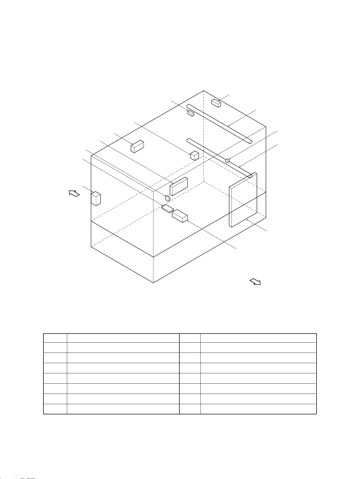
[B] DC electrical parts (motors)
EM
DQ
EK
DR
DN
[Front side]
No. Name
DM Main motor (MAIN-MOT) (M1)
DN Scanning motor (SCN-MOT) (M2)
DO Lens motor (LNS-MOT) (M3)
DP Mirror motor (MRR-MOT) (M4)
DQ Toner motor (TNR-MOT) (M9)
DR Document motor (DCM-MOT) (M11)
*DS Tray-up motor-1 (T-UP1-MOT) (M13)
EO
EL
EN
DM
DO
DP
DS
ET
[Rear side]
No. Name
ET Tray-up motor-2 (T-UP2-MOT) (M14)
EK Optical fan-F (OPT-FAN-F) (M12)
EL Optical fan-R (OPT1-FAN-R) (M6)
EM Exit fan (EXIT-FAN) (M7)
EN Bottom fan (BTM-FAN) (M8)
EO Optical fan-R (OPT2-FAN-R) (M15)
*: Option
Nov. 1997 © TOSHIBA 2 - 7 3560/70 GENERAL
[C] AC electrical parts
ES
FM
FQ
FN
FR
FP
FO
EQ
FL
FT
[Front side]
No. Name
EP SW power supply (PS-ACC)
EQ Door switch (DOOR-SW) (S2)
ER
EP
FK
[Rear side]
No. Name
FM Thermostat (Option)
FN Damp heater U1 (D-HTR-U1) (Option)
ER Main switch (MAIN-SW) (S1)
ES Lamp regulator PC board (PWA-LRG)
FT Heater lamp (HTR-LAMP)
FK Damp heater L (D-HTR-L) (Option)
FL Thermostat (K-THERMO)
3560/70 GENERAL 2 - 8 Nov. 1997 © TOSHIBA
FO Exposure lamp (EXPO-LAMP)
FP Thermofuse (FU-EXPO)
FQ Fuse PC board (PWA-FUS) (Option)
FR Damp heater U2 (D-HTR-U2) (Option)
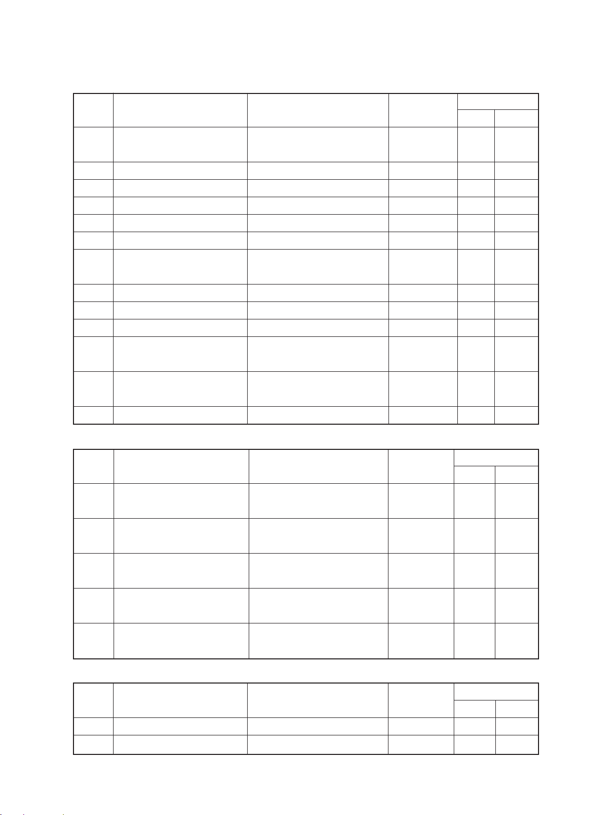
2.2 Symbol and Function of Electrical Parts
(1) Motors
Symbol
M1 MAIN-MOT (Main motor) Drives the drum, developer, IC motor 10 31
M2 SCN-MOT (Scanning motor) Scans the optical system Pulse motor 5 23
M3 LNS-MOT (Lens motor) Drives the lens unit Pulse motor 11 23
M4 MRR-MOT (Mirror motor) Drives the mirror unit Pulse motor 11 23
M6 OPT1-FAN-R (Optics fan-R) Cools the optical system IC motor: Z80 5 8
M7 EXIT-FAN (Exit-fan) Cools the drum and cleaner IC motor: Z80 4 14
M8 BTM-FAN (Bottom fan) Prevents the paper from floating IC motor: Z80 4 14
M9 TNR-MOT (Toner motor) Replenishes the toner Brush motor 24 30
M11 DCM-MOT (Document motor) Drives copy-area indicators Pulse motor 9 2
M12 OPT-FAN-F (Optical fan-F) Cools the optical system IC motor: Z60 4 39
M13 T-UP1-MOT (Tray-up motor-1) Drives the upper cassette tray to Brush motor 12 36
M14 T-UP2-MOT (Tray-up motor-2) Drives the lower cassette tray to Brush motor 12 36
Code name
heat roller and transport belt
up through suction
lift up/down
lift up/down
Function
Remarks
Parts list
Page Item
M15 OPT2-FAN-R (Optics fan-R) Cools the optical system IC motor: Z80 5 8
(2) Electromagnetic spring clutches
Parts list
Symbol
CLT1 RGT1-CLT Transmits transport-roller drive. 13 17
(Transport-roller clutch)
CLT2 RGT0-CLT Transmits aligning-roller drive. 16 16
(Aligning-roller clutch)
CL T3 FED1-CLT Transmits feed-roller clutch 12 24
(Feed-roller clutch-1) drive. (Upper cassette)
CLT4 MFED-CLT Transmits manual-feed roller 15 17
(Manual-feed roller clutch) clutch drive.
CL T5 FED2-CLT Transmits feed-roller clutch 12 24
(Feed-roller clutch-2) drive. (Lower cassette)
Code name
Function
Remarks
Page Item
(3) Counters
Parts list
Symbol Code name
Function
Remarks
Page Item
T T-CTR (Total counter) Total counter 7-digit 3 32
K K-CTR (Key-copy counter) Individual counter 6-digit (option) 101 5
Nov. 1997 © TOSHIBA 2 - 9 3560/70 GENERAL

(4) Switches
Parts list
Symbol
S1 MAIN-SW (Main switch) Power supply Tumbler type 6 3
S2 DOOR-SW (Door switch) For safety, cancels abnormal Push switch 6 4
S3 EMP1-SW Detects lack of paper in the upper Photointerruptor 12 32
S4 U-COV-SW For safety, detects open/closed Push switch 2 27
Code name
condition
(Paper-empty switch-1) cassette
Function
Remarks
Page Item
(Side door switch)
S5 SIZE1-SW (Size switch-1) Detects upper cassette size Push switch 14 31
S6 M-FED-SW Detects manual feeding Photointerruptor 15 3
(Manual-feed switch)
S7 PSTP1-SW Detects paper in front of the Photointerruptor 14 15
(Paper stop switch-1) upper transport roller
S8 PSTP0-SW Detects paper in front of the Photointerruptor 16 20
(Aligning switch) aligning roller
S9 EXIT-SW (Exit switch) Detects exiting paper Photointerruptor 29 8
S10 HOME-SW (Home switch) Detects home position of the Photointerruptor 11 8
S11 LNS-SW (Lens switch) Detects home position of the lens Photointerruptor 11 8
S12 MRR-SW (Mirror switch) Detects home position of the mirror Photointerruptor 11 8
S13 T-FUL-SW Detects when the used toner bag Push switch 10 25
(Toner-full switch) is full
S14 EMP2-SW Detects lack of paper in the lower Photointerruptor 12 32
condition of paper jam release cover
optical system
unit
unit
(Paper-empty switch-2) cassette
S15 SIZE2-SW Detects lower cassette size Push switch 14 31
(Size switch-2)
S16 PSTP2-SW Detects paper in front of the lower Photointerruptor 2 26
(Paper stop switch-2) transport roller
S27 PTN-SW Detects open/closed condition of Photointerruptor 5 38
(Platen switch) the platen cover
S28 T-UP1-SW Detects the position of the upper Photointerruptor 12 32
(Tray-up-1 switch) cassette tray
S29 T-UP2-SW Detects the position of the lower Photointerruptor 12 32
(Tray-up-2 switch) cassette tray
3560/70 GENERAL 2 - 10 Nov. 1997 © TOSHIBA
(5) Heaters and lamps
Parts list
Symbol
EXP EXPO-LAMP Exposes the original Halogen lamp 19 13
HTR HTR-LAMP (Heater lamp) Fixing Halogen lamp 26 6
ERS ERS-LAMP Discharges the drum Fuse type 4 12
DCH DCH-LED To interrupt the charge LED 4 10
Code name
(Exposure lamp) 300W
(Discharge lamp)
(LED eraser array)
Function
Remarks
900W
(100V series)
1030W
(200V series)
Page Item
DHU1
DHU2
DHL D-HTR-L (Damp heater L)
D-HTR-U1 (Damp heater U1) Keeps optical system warm (option)
D-HTR-U2 (Damp heater U2) Keeps optical system warm (option)
Keeps the drum and transfer/separation
charger case warm (option)
Cement resistor 102 4
Cement resistor 102 4
Cement resistor 7 30
(6) PC boards
Symbol
LGC PWA-LGC (Logic PC board) Controls the entire copier 8 15
PNL PWA-PNL Controls control panel 3 33
(Control panel PC board)
KEY1 PWA-KEY1 Controls operation keys 3 11
(Key PC board)
KEY2 PWA-KEY2 Controls operation keys 3 14
(Key PC board)
LRG PWA-LRG Controls exposure lamp 5 20
(Lamp regulator PC board)
Code name
Function
Remarks
Parts list
Page Item
DCH K-DCH Turns on and drives LED during 4 10
(LED eraser array PC board) reduction
ERS PWA-ERS Discharge lamp 4 12
(Discharge lamp PC board)
AES PWA-AES Reads dark/light of the original 18 37
(Automatic exposure PC board)
FUS PWA-FUS (Fuse PC board) Fuse for the damp heater circuit 7 31
Nov. 1997 © TOSHIBA 2 - 11 3560/70 GENERAL
(7) Transformers
Parts list
Symbol
HVT PS-HVT (Charging transformer) Generates high voltage electricity
ACC PS-ACC Power supply for whole copier 8 7
(Power supply for all) power
Code name
for charging (negative voltage)
(Transfer/separation Generates high voltage electricity
transformer) for transfer/separation and
developing bias voltage
(Transfer bias Generates bias voltage to raise
transformer) transfer efficiency
Function
Remarks
Mono unit type 7 27
Page Item
(8) Solenoid
Parts list
Symbol
SOL1 SCRP-SOL Drives the separation claws for the drum 4 42
Code name
Function
Remarks
Page Item
(Separation claw solenoid)
(9) Others
Parts list
Symbol
ATS SNR-ATC Reads toner density with a magnetic 24 33
THMS1 THMS1-HTR Detects temperature of the heat roller 27 19
THMS2 THMS2-HTR Detects the temperature of the heat roller 27 27
THERMO K-THERMO Prevents abnormal heating of heat roller 27 8
FU FU-EXPO (Thermofuse) Prevents abnormal heating of the 19 12
Code name
(Auto-toner sensor) sensor
(Heat-roller thermistor-1)
(Heat-roller thermistor-2) end
(Thermostat)
exposure lamp
Function
Remarks
Page Item
3560/70 GENERAL 2 - 12 Nov. 1997 © TOSHIBA
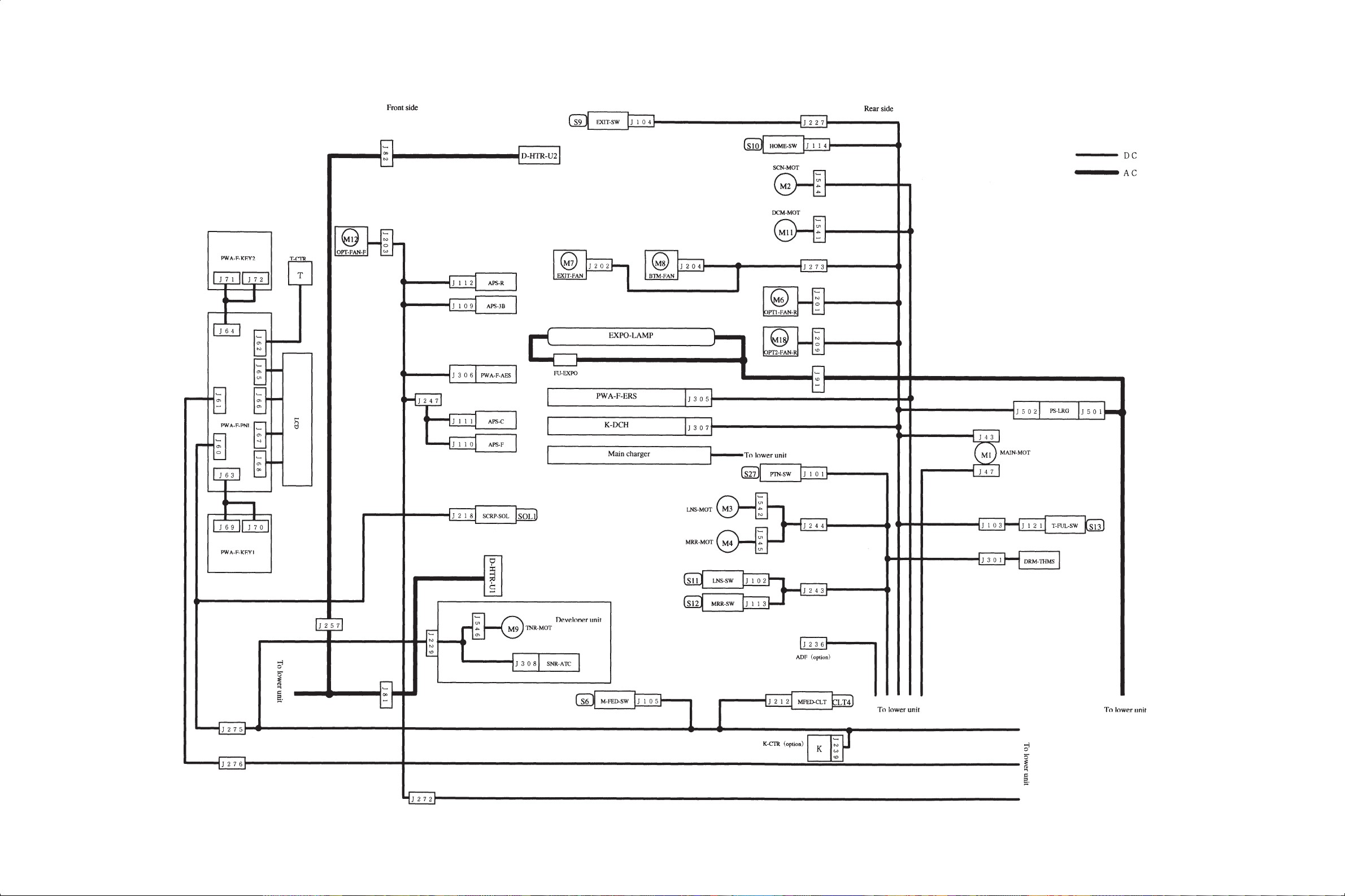
2.3 Wire Harness Location Diagram
[A] Location diagram for upper unit
Nov. 1997 © TOSHIBA 2 - 13 3560/70 GENERAL
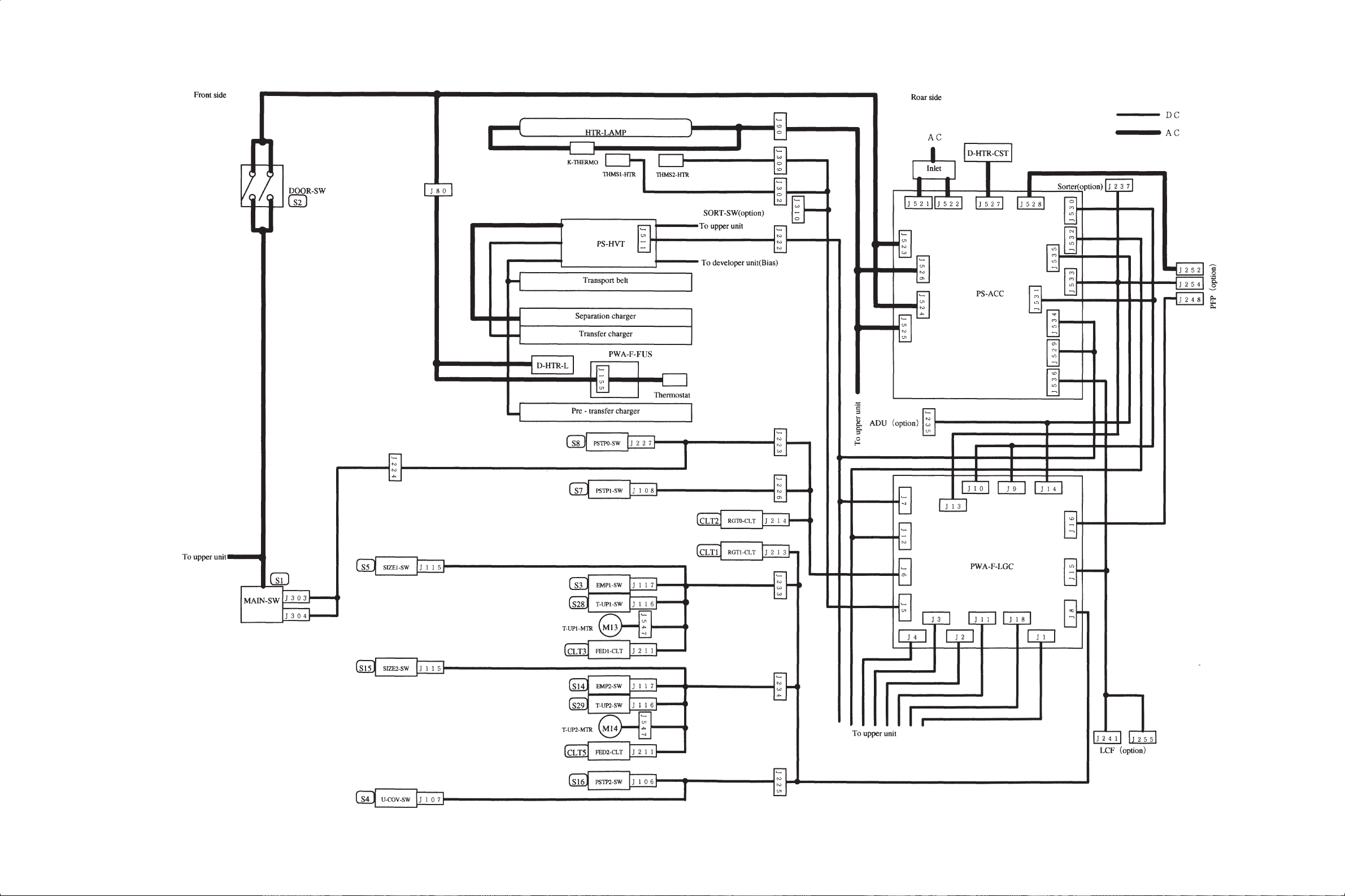
[B] Location diagram for lower unit
3560/70 GENERAL 2 - 14 Nov. 1997 © TOSHIBA

2.4 Removal of Covers and PC Boards
The above item 2.4 is the same one as for 2060/2860.
Changes for the 3560/70
1. The front cover , the inner cover , the upper exit co ver and the left top cov er have slightly been changed.
2. The control panel has slightly been changed to accommodate a graphic touch panel.
COSMOS
Texts from 2-15 in the
3560/70 Service Manual
the same as texts from 2-15 to 2-19 in the
70 Service Manual
Do you refer to the
.
2060,2860/70 Service Manual
SkipOK
Cancel
are
2060,2860/
?
Nov. 1997 © TOSHIBA 2 - 15 3560/70 GENERAL
3. COPYING PROCESS
The above item 3 is the same one as for the 2060/2860 except for the transfer value.
Transfer value
2060/2860 3560/70
–DC 5.25KV –DC 5.10KV
COSMOS
Texts from 3-1 in the
3560/70 Service Manual
same as texts from 3-1 to 3-3 in the
Service Manual
Do you refer to the
.
2060,2860/70 Service Manual
SkipOK
are the
2060,2860/70
?
Cancel
Nov. 1997 © TOSHIBA 3 - 1 3560/70 PROCESS

4. COPIER OPERATION
The above item 4 is the same one as for the 2060/2860 except for page 4-3.
COSMOS
Texts from 4-1 in the
3560/70 Service Manual
same as texts from 4-1 to 4-13 in the
Service Manual
Do you refer to the
.
2060,2860/70 Service Manual
SkipOK
are the
2060,2860/70
?
Cancel
Nov. 1997 © TOSHIBA 4 - 1 3560/70 OPERATION
3560/70 change item
1. The optical fan became 3 pieces (M6, M12, M15) from 2 pieces.
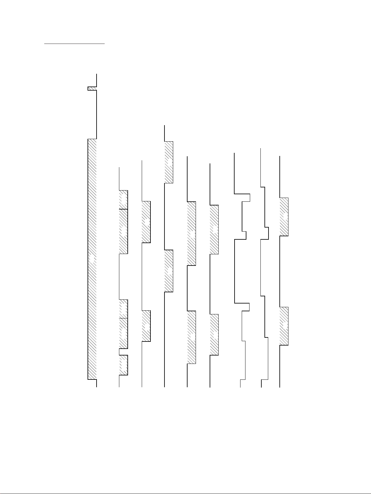
2. The timing chart has been changed.
5.87 7.27 7.30
CW
4.10
3.682.532.411.990.840.2
BWDFWD
BWDBWD
xxx
5.62
4.523.932.82
ON
ON
3.80
2.40 3.72
2.03
ON
OFF
4.05
OFF
2.35 2.86
3.793.06
2.10
High
High
LOWLOW
4.16
3.16
2.86
2.46
3.982.892.291.20
ONON
High
ON ON
0.71
HVT-M
ON
1.37
0.1
OFF
1.47
OFF 0.1
0.1
MAIN-MOT
SCN
FWD
0.72
1.02 2.12 2.71 3.81
RGT
ON ON
0.44 2.11 2.13
EXPO
EXIT-SW
3560/70 OPERATION 4 - 2 Nov. 1997 © TOSHIBA
5. DISPLAY UNIT
The display unit consists of key switches for copier operation/selection of each mode, LEDs and an LCD
displaying the copier state or messages.
Particularly, when the operator’s attention is recommended, a graphic symbol lights or flashes and the
message indicating that condition is displayed.
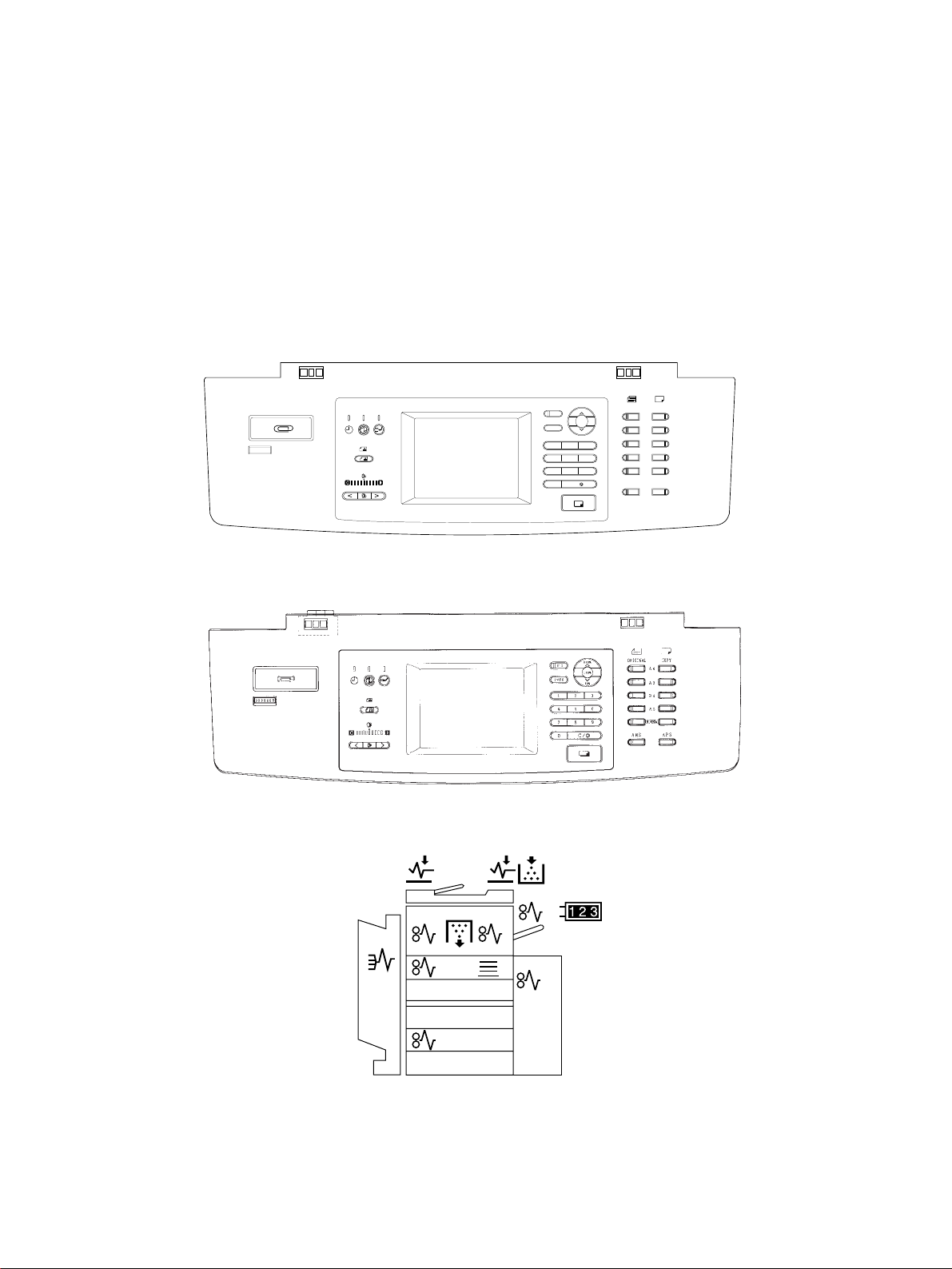
5.1 Detailed Drawing of the Control Panel and the Display Panel
For the U.S.A. and Canada
ZOOM
TIMER
ENERGYSAVER
IMAGEMODE
LIGHT AUTO DARK
INTERRUPT
FUNCTION CLEAR
FC
HELP
123
456
789
0
PRINT
CLEAR/STOP
C
ORIGINAL
200%
100%
50%
/
LD
LG
LT
ST
OTHER
AMS APS
COPYSIZE
For Europe
Arrangement of the control panel
Details of the display panel
Nov. 1997 © TOSHIBA 5 - 1 3560/70 DISPLAY
5.2 Items Shown on the Display Panel
5.2.1 Display during normal copying
No. Message Conditions of machine Notes
1 WAIT WARMING UP Being warmed up • The number and reproduction ratio
• Indicated after the main switch
is switched on up until the example, as “0”, “100%” when the
machine becomes capable of main switch comes on.
copying.
2 READY Capable of copying. •
• Indicated when the machine is “1”. When a digital key is pressed,
capable of copying and the the set number is indicated.
operator’s instructions for •
copying conditions are awaited. pressing the CLEAR/STOP key .
• Returns to the initial condition • Manual copying is possible.
if no key input is given for 45
seconds.
3 COPYING Now copying. •
• Indicated by pressing the quantity indicator returns to the
PRINT key. initially set number.
•
Copy quantity indicator becomes
“1” and copying is completed.
4 SAVING ENERGY Energy saving conditions. •
PRESS PRINT
5 PLACE NEXT ADU 1-sided copying standby •
ORIGINAL state. A below. not using ADF.
6 — Timer off • Released by pressing the PRINT
• No message is displayed in the key.
panel except for timer LED.
of the copies are indicated, for
Copy quantity indicator indicates as
The set number is cleared to “1” by
After completion of copying, the copy
Released by pressing the ENERGY
SAVER key or the PRINT key.
When using ADU 1-sided, and when
A
3560/70 DISPLAY 5 - 2 Nov. 1997 © TOSHIBA
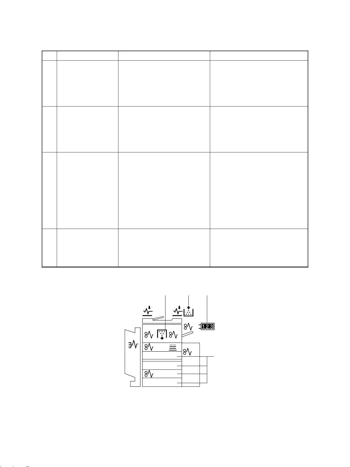
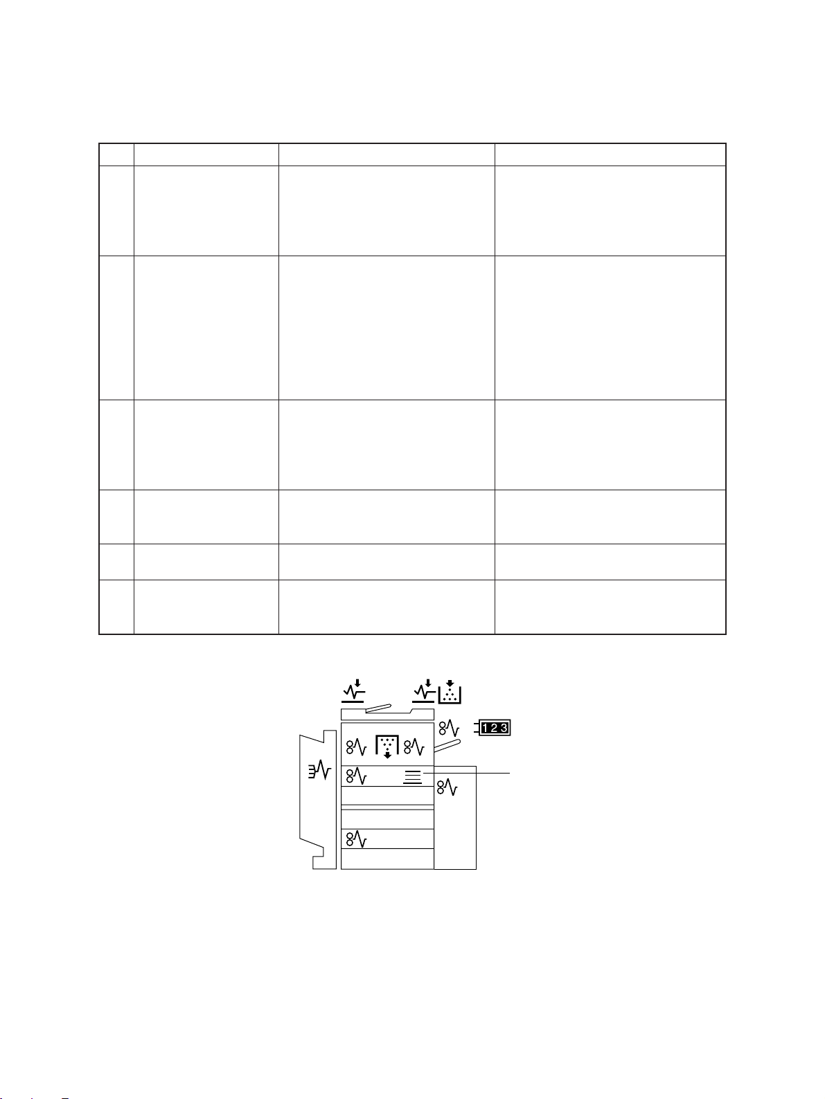
5.2.2 Display in the event of faulty conditions
No. Message Abnormal state & indication Solution
7 ADD PAPER Indication of lack of paper. •Supply paper to the selected
• Flashes when there is no paper cassette.
in the cassette.
• Indicates which cassette has no
paper. (A below.)
• Manual copying is possible.
8 ADD TONER: Indication of lack of toner. • Released after the cartridge is
• B below is indicated when replaced and the front cover is
PRESS INFO the toner in the toner cartridge closed.
runs out.
•
When this message is displayed,
it is not possible to copy.
9 INSERT Key copy counter withdrawn. • Released and returned to normal
• Indicated when the key copy conditions by inserting the key
KEY COPY COUNTER
10 DISPOSE OF Indication of need to replace the Open the front cover and replace
USED TONER • Indicated when the toner bag is
counter is withdrawn when the copy counter.
machine is READY or during
copying. C below.
• When it is removed after
pressing the PRINT key, the
machine stops after that copy is
completed, but the counter
counts it.
toner bag. the toner bag.
full. D below.
The copier stops.
D
B C
A
Nov. 1997 © TOSHIBA 5 - 3 3560/70 DISPLAY
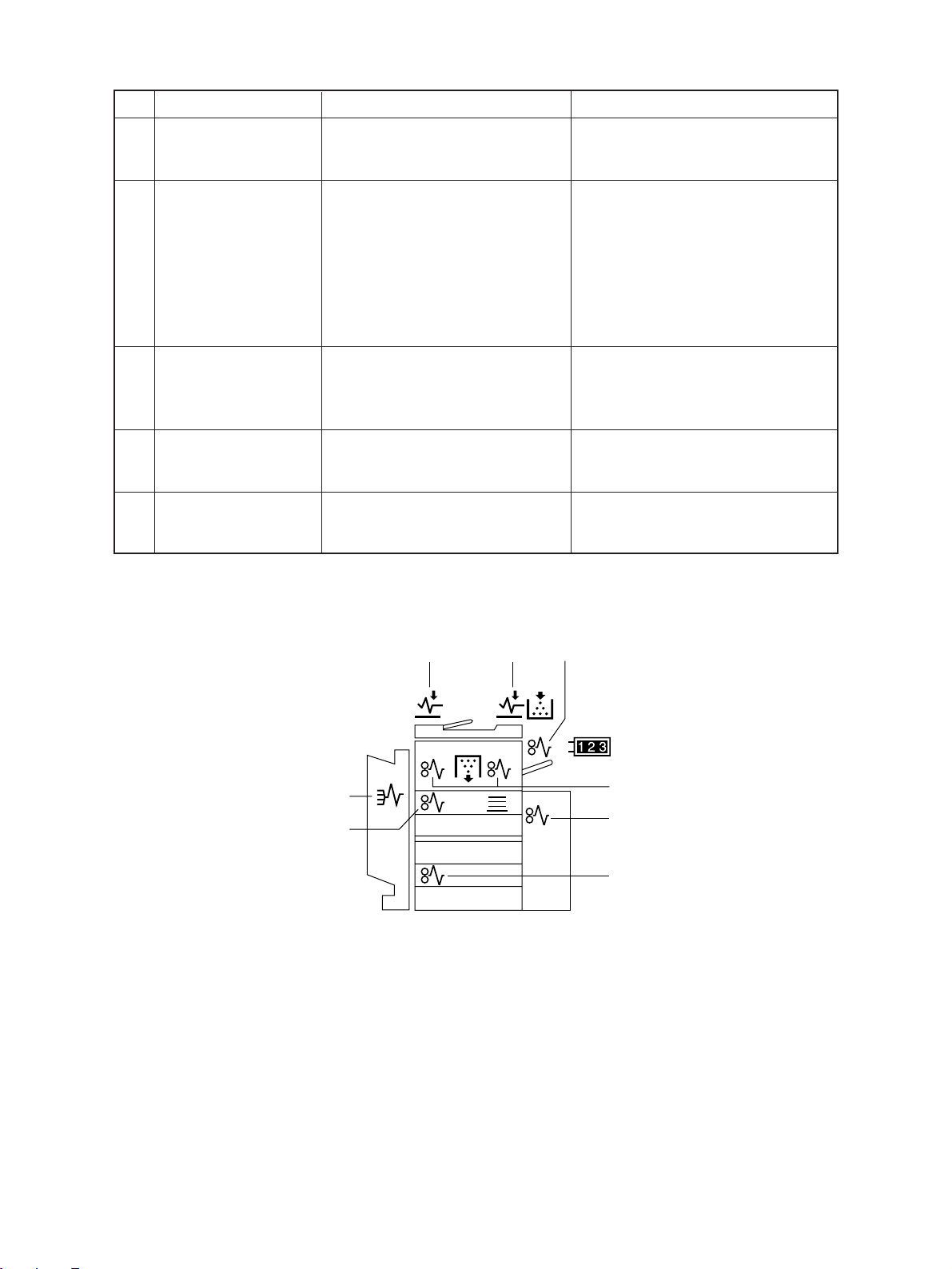
No. Message Abnormal state & indication Solution
11 PAPER MISFEED Bypass paper jamming The machine is returned to normal
• Indicates when paper jams at conditions automatically by pulling
IN BYPASS the bypass guide. A below.
12
MISFEED IN COPIER
PRESS INFO the machine. B below. copier following the message.
13 MISFEED Original jammed Open the ADF feed cover and
IN DOC. FEEDER jammed in the optional
14
MISFEED IN SORTER:
PRESS INFO in the sorter. E below. cover once.
15 MISFEED IN ADU: Indicates when paper is jammed Press the HELP (INFO) key and
PRESS INFO copier following the message.
Paper jammed in the machine. • Press the HELP (INFO) key and
• Indicated when paper jams in remove the paper jammed in the
Misfeed from LCF, PFP
• Indicated when paper fed from
a cassette does not arrive at the
paper-stop switch within a set
time. C and F below.
• Indicated when an original is remove the jammed original.
document feeder. D below
Paper jammed in the sorter. Remove the paper jammed in the
• Indicates when paper is jammed sorter and open and close the front
in the ADU section. G below. remove the paper jammed in the
the paper out from the bypass guide.
E
G
D
D
A
B
C
F
3560/70 DISPLAY 5 - 4 Nov. 1997 © TOSHIBA
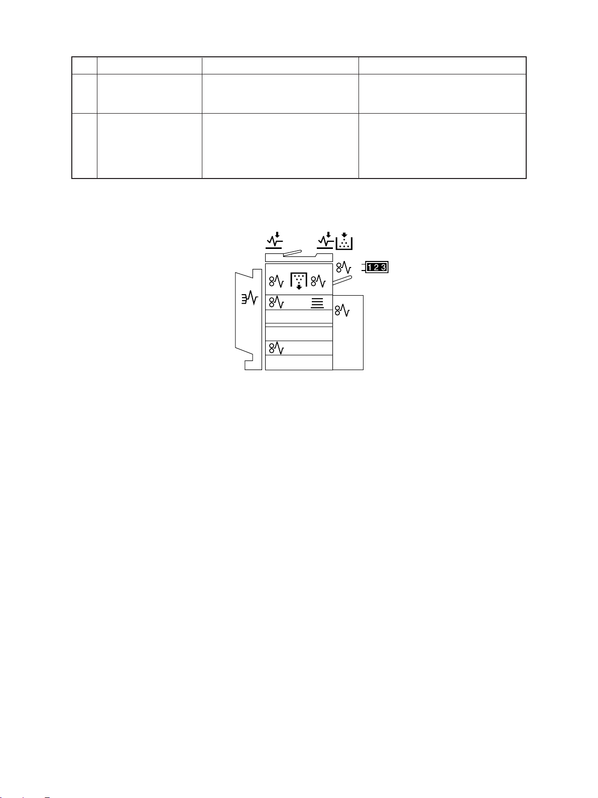
No. Message Abnormal state & indication Solution
16
CALL FOR SERVICE:
Some or one of the mechanism, Turn off the machine, remove the
motors, switches or sensors are cause of the fault and turn the
CALL abnormal. machine back on.
17
TIME FOR PERIODIC
Indication of PM cycle. Maintenance and inspection by a
• Indicated when it is time for qualified service technician.
MAINTENANCE periodic maintenance and
inspection.
• Capable of copying.
Nov. 1997 © TOSHIBA 5 - 5 3560/70 DISPLAY
 Loading...