

Toshiba 19SL400U, 22SL400U, 26SL400U, 32SL400U Owner's Manual
TOSHIBA
Leading
Ownlr's
Integrated
LCD
COLOR
III
DD~~~~I
Innovation
»>
Manual
High
Television
5TREn
M®HO
~,,~,m.~~
Definition
~v'
111111111111111111111111111111111111111111111111111111111111I1111
Dear
Thank
manual
of
please
nearby
Customer,
you
for
will
help
your
new
LCD
read
this
for
future
Safety
WARNING:
OR
Precautions
ELECTRIC
purchasing
you
TV.
manual
this
use
the
Before
completely,
operating
reference.
TO
REDUCE
SHOCK,DONOT
Toshiba
many
exciting
THE
RISKOFFIRE
EXPOSE
APPLIANCETORAINORMOISTURE.
WARNING:TOREDUCE
SHOCK,DONOT
NO
USER·SERVICEABLE
REFER
SERVICINGTOQUALIFIED
REMOVE
THE
RISKOFELECTRIC
COVER
PARTS
PERSONNEL.
The
~
&
•
Lh
lightning
equilateral
presenceofuninsulated
product's
to
constituteariskofelectric
The
exclamation
intendedtoalert
operating
the
literature
flash
with
arrowhead
triangle.isintendedtoalert
"dangerous
enclosure
that
maybeof
shocktopersons.
point
withinanequilateral
the
usertothe
and
maintenance
accompanying
presenceofimportant
(servicing)
the
WARNING
To
prevent
attachedtothe
installation
WARNING:
television,
appropriate
The
wall
television
in
serious
"Removing
NOTE
Thisisa
attentiontoArticle
provides
particular,
connectedtothe
as
closetothe
additional
32
and33on
injury,
floor/wallinaccordance
instructions.
always
for
useofany
bracket
appropriate
for
wall
bodily
the
TO
CATV
remindertocall
guidelines
specifies
POintofcable
antenna
page
this
apparatus
See
item25on
If
you
decidetowall
useaUL
the
size
wall
bracket
mounting
injury
Pedestal
Listed
and
weightofthis
other
for
the
this
and/or
Stand"(~page
INSTALLERS
the
CATV
820-40ofthe
for
proper
that
the
cable
grounding
grounding
4.
systemofthe
entryaspractical.
information,
mustbesecurely
mount
wall
thanaUL
size
and
television
property
system
U.S.
grounding
ground
LCD
TV.
features
your
LCD
and
keep
THIS
(OR
BACK).
INSIDE.
SERVICE
symbol.
within
the
usertothe
voltage"
sufficient
triangle
instructions
appliance.
with
the
page
this
bracket
television.
Listed
weightofthis
could
damage.
6).
installer's
NEC,
which
and,
shall
building,
see
This
TV,
it
an
within
the
magnitude
is
in
4.
result
See
in
be
For
items
CHILD
It
MakesADifference
Panel
Display
Congratulationsonyour
new
product,
The
Issue
•
The
home
and
larger
flat
panel
displays
or
installed
Tune
Into
•
One
size
does
for
the
safe
•
Carefully
proper
•
Don't
television
•
Don't
furniture
steps,
•
Remember
become
program.
than
shouldbetakentoplaceorinstall
the
pushed,
•
Care
cables
pulledorgrabbedbycurious
Wall
flat
•
Useamount
manufacturer
as
•
Follow
manufacturers.
•Ifyou
flat
installation.
•
Make
appropriate.
to
are
installer.
• A
required
displays
read
useofthis
allow
place
that
suchasa
excited
life"
flat
display
pulled
shouldbetakentoroute
connectedtothe
Mounting:Ifyou
panel
UL,
eSA,
all
have
panel
sure
walls
with
unsure,
minimumoftwo
for
canbeheavy.
SAFETY:
How
purchase!Asyou
please
keep
theater
entertainment
flat
panel
displays
are
not
always
accordingtothe
•
Flat
inappropriately
entertainment
Safety
NOT
fit
all.
Follow
installation
childrentoclimbonor
sets.
flat
that
especiallyona
whereitcannot
display,
instructions
any
display,
that
contactaprofessional
and
and
understand
product.
panel
displays
can
easilybeused
chestofdrawers.
children
can
while
watching
panel
display.
over,orknocked
flat
always:
that
has
been
and/or
listedbyan
ETL).
suppliedbythe
doubts
about
contact
the
wall
where
Some
wall
mounts
steel
studsorold
people
installation.
Flat
useofyour
"larger
Care
be
decidetowall
recommendedbythe
your
are
and
Where
You
these
safety
tipsinmind:
experienceisa
are
popular
purchases.
supportedonthe
manufacturer's
panel
displays
bookcases,
speakers,
over
and
TOSHIBA
•
The
consumer
is
committedtomaking
the
manufacturer's
all
enclosed
play
on
as
a
down.
all
cords
panel
displaysothat
children.
independent
your
abilitytosafely
retailer
you
are
are
cinder
panel
recommendations
that
situatedondressers,
shelves,
chestsorcarts
cause
Cares!
electronics
enjoyable
flat
panel
display.
instructions
with
furniture
and
display
about
professional
mounting
not
designedtobe
block
construction.Ifyou
www.CE.org/safety
Use
Your
Flat
enjoy
your
growing
are
injury.
recommendations
mount
laboratory
and
However,
proper
desks,
home
and
they
display
wall
install
the
display
trend
stands
may
industry
safe.
for
and
cannot
your
(such
mount
your
mounted
.
fall
be
is
2

Important
1)
Read
2)
Keep
3)
Heed
4)
Follow
5)
Do
~~---~._""-----------._-~-~-~~----~.---'---'-'-"'--~-----"~--'--------'-~---'-'-'----'
§L_~~~_~_~_~_'!~Y
7)
Do
accordance
8)
Do
not
radiators,
(including
--_._."_.,,_._._._---~,---~-~~_.~..~_._---~.----,~_."-~._._~
9)
Do
or
grounding
plug
than
plug
grounding
or
the
provided
an
..
_
..
_--_
..
__
Protect
or
electrician
._--_.~-,-,--._.---_.~--_._-----_
pinched,
.
~,-._
10)
convenience
where
11)
Only
manufacturer.
__
,"''"_'.'
.
12)
Use
table
sold
used,
cart/apparatus
___.__
i~J~~X_!E~f!l_!ip=~~~~:
13)
Unplug
.
E_~
__
~~~~_!~_~~~~._!~!~_~1I.1~_~~~_~~_~_f.!~I!I.!'_:
14)
Refer
personnel.
apparatus
as
power-supply
has
apparatus,
rainormoisture,
has
Additional
14a)
CAUTION:
enclosure
not
•
ALWAYS
cordtoavoid
•
NEVER
Safety
these
instructions.
these
instructions.
all
warnings.
all
instructions.
not
use
this
with
not
block
any
with
install
heat
amplifiers)
not
defeat
type
has
two
blades
the
other.Agrounding
has
two
blades
prong.
third
prongisprovided
plug
for
the
power
Instructions
apparatus
dr~
clot~:-
ventilation
the
manufacturer's
near
any
heat
registers,
the
does
replacementofthe
stoves,orother
that
..
--------~-_
safety
purposeofthe
plug.
A
with
one
andathird
The
wide
not
fit
•.
_--------._-"---_.,---_
cord
from
particularlyatplugs,
receptacles,
they
exit
from
use
attachments/accessories
,_'_e__'_.'',,,,__• • ·__._.
only
with
the
specifiedbythe
with
the
apparatus.
use
caution
and
the
apparatus.
• ,.•,_.•__,__•..•.'__._.
cart,
stand,
manufacturer,
Whenacart
when
moving
combinationtoavoid
._____.
this
apparatus
all
servicingtoqualified
Servicingisrequired
has
been
been
spilledorobjects
the
apparatus
been
dropped.
Safety
If
theTVis
surface
operate
normally,
turn
allow
off
possible
your
during
damagedinany
cordorplugisdamaged,
does
not
Precautions
dropped
has
been
take
theTVand
bodytocomeincontact
near
water.
._
..
openings.
Install
instructions.
sources
such
as
apparatus
produce
heat.
..
~-._--._""----------_._--_.,.
__
._--,------_._--
polarized
polarized
Wide
blade
wider
type
•
blade
for
your
safety.Ifthe
into
your
outlet,
consult
..
_._"
being
the
obsolete
.."..
_---,-'---_.~-~--,_._-._
walked
point
.•..
on
outlet.
_----,---.-.-
specifiedbythe
. ..•.•".•"••.•." ,__.•',,
tripod,
bracket,
or&)
is
J!1
the
lightning
•
. . .
~
~
9:~
__
=.
storms
.__
service
when
the
way,
such
liquid
have
fallen
into
the
has
been
exposed
operate
and
normally,
the
cabinet
damagedortheTVdoes
the
following
unplug
electric
shockorfire.
to
or
precautions:
the
power
in
or
or
..
~
~
with
any
broken
television.
glass
contact
is
cutbybroken
thoroughly
•
ALWAYS
TV
-_._._._-----_._--,_._--"-_._----~~-~--_._--"._--------~--_.
15)
.
any
CAUTION:
•Toreduce
use
the
receptacle,orother
be
inserted
•Toprevent
to
---_._._~_._,--,'",._._-,--------_
16)
wide
CAUTION:
Do
not
the
plastic
outofthe
17)
CAUTION:
Do
not
with
..
_._,."_.-,-"."._,,,-,,,,--_._---,-,--,._.,,_
',-'
18)
the
WARNING:
•Toprevent
open
•
Keep
a
heat
product
Installation,
glassorliquid
The
LCD
panel
andatoxic
with
liquid.Ifthe
your
mouthoreyes,oryour
glass,
with
water
contactaservice
timeithas
the
polarized
been
riskofelectric
plug
withanextension
outlet
completelytoprevent
slot;
let
children
bag.
..
electric
_-,,-,."-~-~,-~._.,---_._.",--_._._.,.-----"--._-
fully
Keep
shock,
insert.
swallow
the
product
reachofchildren.
let
waterorother
product,asit
..
_---_._._
..
,,---,
the
spreadoffire,
flames
away
the
product
source
suchasa
liquids
may
..
_---------_._._
from
away
from
lifetimeorresultinfire.
Care,
and
from
the
damaged
inside
theTVcontains
liquid
comes
skin
rinse
the
and
affected
consult
your
area
doctor.
techniciantoinspect
damagedordropped.
__
._------_._----'---_..,-_..,._----_._._-
shock,donot
cord,
unless
the
blades
blade
exposure.
match
wide
bladeofplug
...
",,,,--_
...
_._-,-._._"--_._-"----_._-"-_._,-_._,,,.
the
productorplay
and
the
plastic
come
into
contact
resultindamage.
....
_,-~--,,--_.
__
...
__
._---_._,,--.----._------_._---"
keep
candlesorother
this
productatall
direct
heater.
sunlight,
This
may
times.
fire
reduce
Service
in
can
with
bag
.._...
the
__
_
or
the
.-
..
-
Installation
_
Follow
heed
19)
.."
..
20)
.'
21)
_._..".._----._--_._--_.,.._--_.__._.-_,---_.._-_
22)
---,---"
23)
these
recommendations
all
_
..
_,,..
--
..
....._..
-."
warnings
'~'-"'_'_-"'--'-'----'
..
Lh
•
...'..
--.
''''.
_._._._._,
...
_._---._-,---,--_.-
ALWAYS
"."""
-"
,---
---._--,---'
WARNING:
to
fireorthe
..
plug
the
when
excessive
_---~.
locatedinsuchamanner
unpluggedincase
.",
--"-"'-
..
----.----
..
_._.,,---------------_._._-----.-_._._---------.,,-
NEVER
or
Never
modifications
user's
rulesofthe
...
_~."""-_._--
Lh
route
the
similar
enclosed
modify
this
may
authoritytooperate
Federal
..
_----
...
,--._
..
~--"-,---"~.
DANGER:
INJURY,
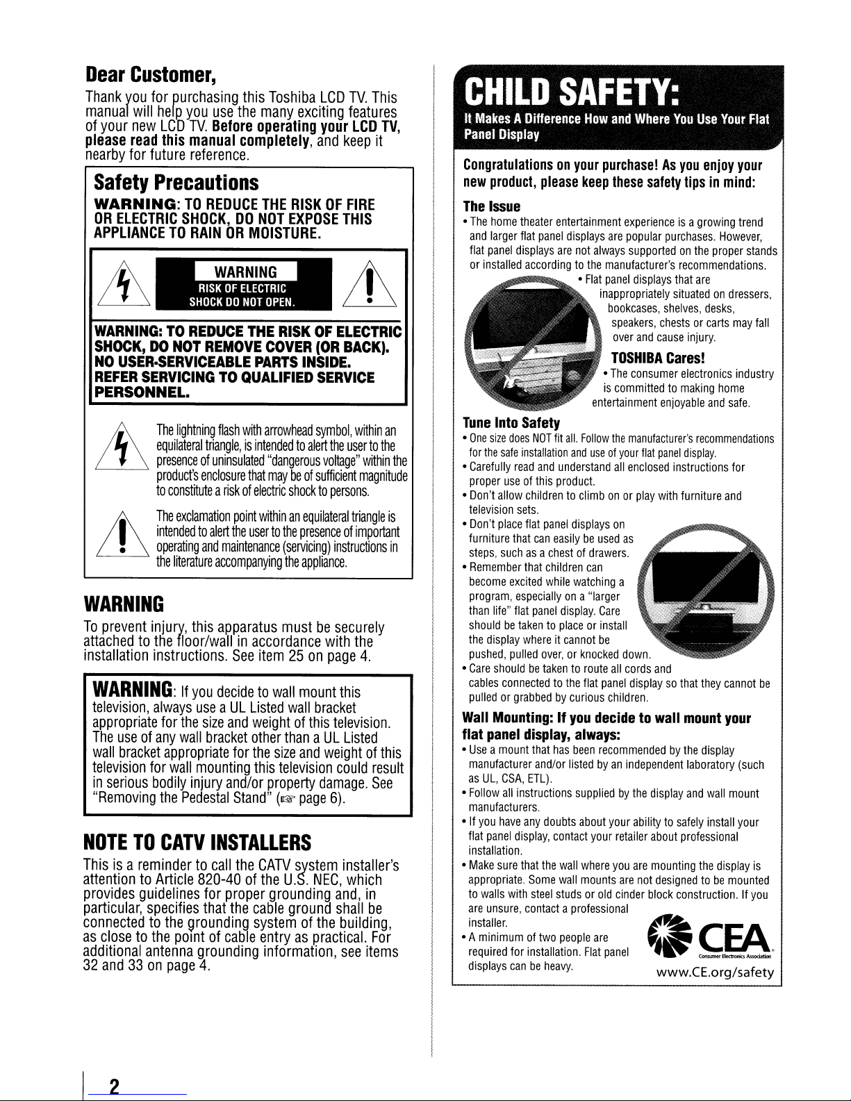
•
EQUIPMENT
Never
place
theTVonanunstable
cart,
.stand,
.or
table.
causing
serious
death,orserious
and
installing
..
_-_._._-_._".--.-_
.."..
----
_
NEVER
heat
like
__
._.<---_._-'_
product
.
....
--_._--._-_.__.__._"_
intoanoutlet
thatitcanbeeasily
the
product
•.
_--
product's
area.
..
_-_._-,~
equipment.
..
,.".-.".-.".
__
.~_
.."..
power
"_._
...
_._
Changes
void:a)the
this
Communications
__
...
~,-,----,-~-_._~-_._-_.
RISKOFSERIOUS
DEATH,
OR
DAMAGE!
The~.may
personal
Injury,
damagetotheTV.
precautions
your
TV:
,,_
__
_._---
_
expose
,._---_._.
and
__
.
__
.-."
_--,
batteries
suchassunshine,
...
_.~
..
'_.--
------_......
,._--.__.._....
that
is
requires
..
_
...
--_
..
_.,,,."-,,.-~"
.....
_._-->..-_-_..-----"._'"
.... ,_.,
..
'"
cord
insideawall
..
--"""'._~,------
service.
_.'----
---------,---,-_.
...
_--,._---.,,--,
or
warranty,
equipment
andb)the
under
Commission.
__
._-"--,_
.•
_--_._-,,.~--._,._-"
PERSONAL
&)
~~
fall,
~
~
'i., -
(continued)
_._--
__
the
-----
._-"
_.--.
...
-
3
24)Toavoid
theTVin
subjecttoexcessive
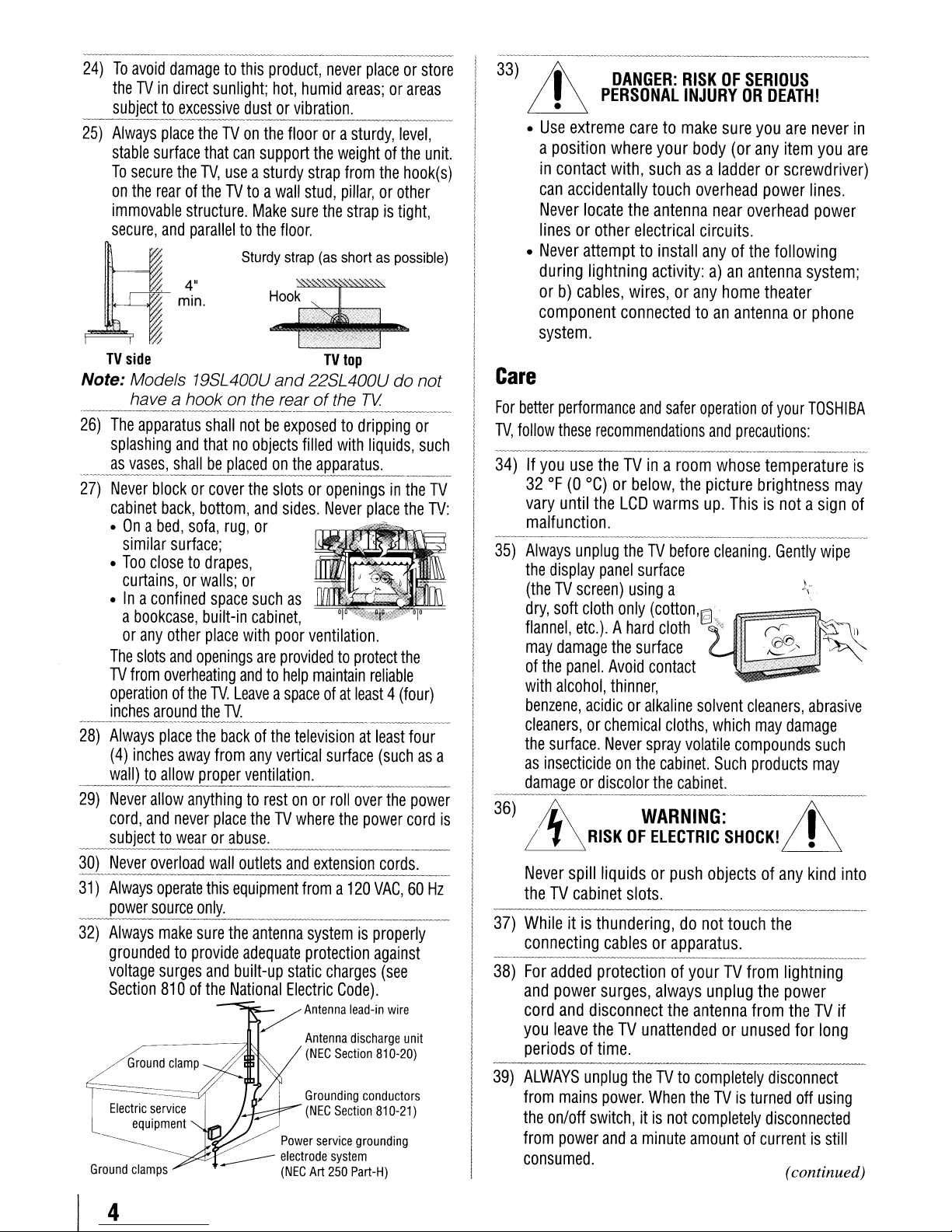
25)
Always
stable
To
on
immovable
secure,
TV
Note: Models 19SL400U
26)
The
splashing
.
__
a~vas~~~~11
27)
Never
cabinet
•Ona
•
•Ina
The
TV
operationofthe
inches
--------------------
28)
Always
(4)
wall)toallow
29)
Never
cord,
damagetothis
direct
sunlight;
dustorvibration.
place
theTVon
surface
secure
the
rearoftheTVtoawall
~
side
have a hook on the rearofthe
apparatus
blockorcover
bed,
similar
Too
closetodrapes,
curtains,orwalls;
confined
a
bookcase,
or
any
slots
from
around
inches
allow
and
that
can
the
TV,
useasturdy
structure.
and
paralleltothe
4"
min.
shall
and
thatnoobjects
Make
Sturdy
notbeexposedtodripping
be
placedonthe
the
back,
bottom,
sofa,
rug,
and
or
surface;
or
space
such
built-in
other
place
and
openings
overheating
the
place
the
away
proper
cabinet,
with
andtohelp
TV.
Leaveaspaceofat
TV.
backofthe
from
any
ve~tilatio_n.
anythingtorestonor
never
place
theTVwhere
support
are
subjecttowearorabuse.
~_L~~'yer
31)
32)
Ground
Always
power
Always
overload
operate
source
make
wall
this
only.
sure
the
groundedtoprovide
voltage
Section
Electric
surges
810ofthe
Ground
service
equipment
clamps
and
clamp
______
outlets
equipment
antenna
adequate
built-up
National
product,
hot,
never
humid
placeorstore
areas;orareas
._------
the
floorora
stud,
sure
sturdy,
the
weightofthe
strap
from
pillar,orother
the
strapistight,
the
floor.
strap
(as
shortaspossible)
TV
top
and
22SL400Udonot
with
TV
liquids,
----------
filled
apparatus.
slotsoropeningsinthe
sides.
Never
place
as
poor
ventilation.
providedtoprotect
maintain
reliable
least4(four)
-----------
televisionatleast
vertical
surface
(suchasa
_
rollover
the
the
power
---
and
/
extension
froma120
systemisproperly
protection
static
charges
Electric
Antenna
Antenna
(NEC
Grounding
(NEC
Power
service
electrode
(NEC
Art
system
250
Code).
lead-in
discharge
Section
conductors
Section
grounding
Part-H)
cords.
VAC,60Hz
against
(see
wire
810-20)
810-21)
level,
unit.
hook(s)
or
such
TV
the
TV:
the
four
power
cord
unit
._-------------
33)
Lh
-------
DANGER:
PERSONAL
RISKOFSERIOUS
INJURYORDEATH!
•
•
Use
extreme
a
position
in
contact
can
accidentally
Never
linesorother
•
Never
during
orb)cables,
component
caretomake
where
your
with,
suchasa
touch
locate
the
antenna
electrical
attempttoinstall
lightning
activity:a)an
wires,orany
connectedtoan
sure
you
are
body
(or
any
item
ladderorscrewdriver)
overhead
near
power
overhead
circuits.
anyofthe
home
following
antenna
theater
system;
antennaorphone
never
you
lines.
power
in
are
system.
Care
For
better
performance
TV,
follow
these
34)Ifyou
32OF(0
vary
until
use
°C)orbelow,
malfunction.
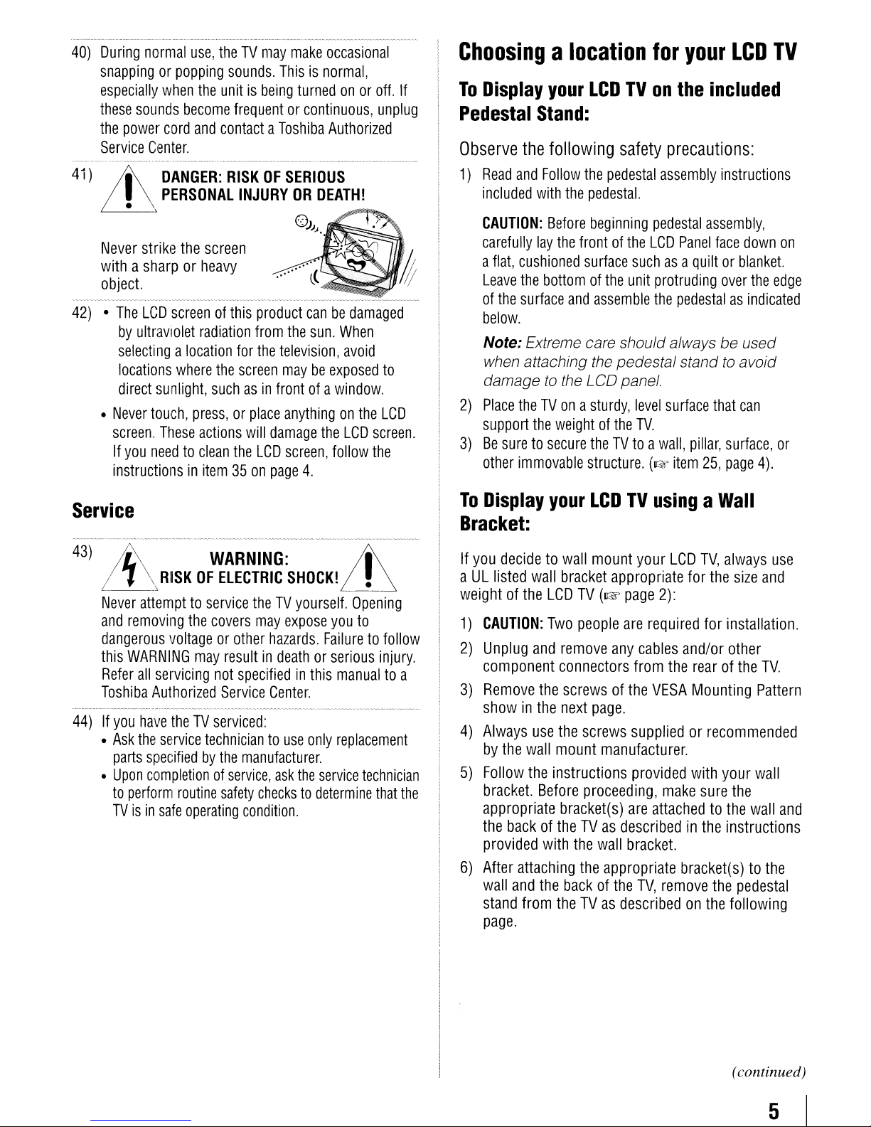
35)
Always
the
unplug
display
(theTVscreen)
dry,
soft
cloth
flannel,
may
of
with
benzene,
etc.).Ahard
damage
the
panel.
alcohol,
acidicoralkaline
cleaners,orchemical
the
surface.
as
insecticideonthe
damageordiscolor
---~-------------------
is
36)
~
~
Never
RISKOFELECTRIC
spill
theTVcabinet
37)
Whileitis
connecting
----~---_._-_._--~-------_."._,------_
38)
For
added
and
power
cord
and
disconnect
you
leave
periodsoftime.
39)
ALWAYS
from
the
from
unplug
mains
on/off
power
consumed.
and
safer
operationofyour
recommendations
theTVinaroom
the
LCD
warms
theTVbefore
panel
surface
using
only
(cotton'I§1
a
the
and
precautions:
whose
picture
up.
cleaning.
temperature
brightness
Thisisnotasign
Gently
...
cloth.."
the
surface
Avoid
contact
thinner,
Never
cloths,
spray
cabinet.
the
solvent
volatile
cabinet.
cleaners,
which
may
compounds
Such
products
WARNING:
SHOCK!
liquidsorpush
slots.
thundering,donot
cablesorapparatus.
protectionofyourTVfrom
surges,
always
theTVunattendedorunused
theTVto
power.
When
switch,itis
andaminute
objectsofany
touch
the
..
~---.-~~_.
unplug
the
antenna
completely
theTVis
not
completely
the
from
disconnect
turned
disconnected
amountofcurrentisstill
TOSHIBA
may
wipe
).
\ .
abrasive
damage
such
may
;j\
in
kind
into
__
lightning
power
theTVif
for
long
off
using
(continued)
is
of
.-.
__
._-
4
40)
During
snappingorpopping
especially
these
the
Service
41)
it
Never
withasharporheavy
object.
42)•The
•
normal
when
sounds
power
cord
Center.
DANGER:
PERSONAL
. \
-,
strike
LCD
screenofthis
by
ultraviolet
selectingalocation
locations
direct
sunlight,
Never
touch,
screen.
If
instructionsinitem35on
These
you
needtoclean
use,
theTVmay
sounds.
the
unitisbeing
become
the
where
frequentorcontinuous,
and
contactaToshiba
RISKOFSERIOUS
INJURY
screen
radiation
for
the
screen
suchasin
press,orplace
actions
the
make
Thisisnormal,
turnedonor
OR
0))
product
from
the
the
television,
maybeexposed
frontofa
anythingonthe
will
damage
LCD
screen,
page
occasional
off.
unplug
Authorized
DEATH!
J.
canbedamaged
sun.
When
avoid
to
window.
LCD
the
LCD
screen.
follow
the
4.
Choosingalocation
If
To
Display
Pedestal
Observe
1)
Read
included
CAUTION:
carefully
a
flat,
Leave
of
the
below.
Note: Extreme care should alwaysbeused
when attaching the pedestal stand
damage
2)
Place
support
3)
Be
suretosecure
other
your
LCDTVon
Stand:
the
following
and
Follow
the
pedestal
with
the
pedestal.
Before
beginning
lay
the
frontofthe
cushioned
the
surface
theTVonasturdy,
the
immovable
surface
bottomofthe
and
assemble
to
the LCD panel.
weightofthe
theTVtoawall,
structure.
for
safety
pedestal
LCD
suchasa
unit
level
TV.
(I@'
your
the
LCD
included
precautions:
assembly
protruding
the
pedestalasindicated
surface
item
instructions
assembly,
Panel
face
down
quiltorblanket.
over
to
avoid
that
can
pillar,
surface,
25,
page
the
4).
TV
on
edge
or
Service
43)
44)Ifyou
~
I~_-_
'\,
Never
and
dangerous
this
Refer
Toshiba
•
Ask
parts
•
Upon
to
TVisin
WARNING:
RISKOFELECTRIC
attempttoservice
removing
WARNING
all
have
the
perform
the
covers
voltageorother
may
resultindeathorserious
servicing
Authorized
service
specifiedbythe
completionofservice,
safe
not
Service
theTVserviced:
techniciantouse
routine
safety
operating
SHOCK!
theTVyourself.
may
expose
hazards.
specifiedinthis
Center.
manufacturer.
ask
checkstodetermine
condition.
Failuretofollow
only
the
service
;j\
~
Opening
you
to
injury.
manualtoa
replacement
technician
that
the
To
Display
Bracket:
If
you
decidetowall
aULlisted
weightofthe
1)
CAUTION:
2)
Unplug
component
3)
Remove
showinthe
4)
Always
by
the
wall
5)
Follow
bracket.
appropriate
the
provided
6)
After
wall
stand
page.
the
backoftheTVas
attaching
and
from
your
wall
bracket
LCD
Two
and
remove
connectors
the
screwsofthe
next
use
the
mount
instructions
Before
bracket(s)
with
the
the
backofthe
theTVas
LCDTVusingaWall
mount
TV
people
page.
screws
proceeding,
the
your
LCD
TV,
appropriate
(I@'
page
are
any
cables
from
suppliedorrecommended
manufacturer.
provided
are
describedinthe
wall
bracket.
appropriate
TV,
describedonthe
for
the
2):
required
VESA
attachedtothe
for
and/or
the
rearofthe
Mounting
with
make
sure
bracket(s)tothe
remove
the
always
installation.
other
your
instructions
following
size
and
TV.
Pattern
wall
the
wall
pedestal
use
and
(continued)
5
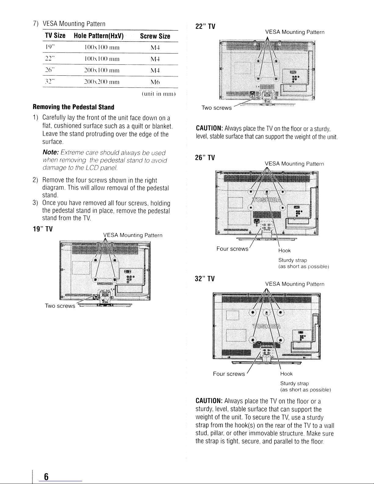
7)
VESA
TV
Size
Mounting
Hole
Pattern
Pattern(HxV)
Screw
Size
22"
TV
VESA Mounting Pattern
19"
,,"
2()"
~2"
Removing
1)
Carefully
flat,
cushioned
Leave
the
the
20()x
20(
Pedestal
lay
the
surface
stand
I00 x 100
I00x 100
100
h 200
Stand
frontofthe
suchasa
protruding
111111
111111
111111
nun
over
unit
face
quiltorblanket.
the
edgeofthe
surface.
Note: Extreme care shouldalways be used
when removing the pedestal stand
to
damage
2)
Remove
diagram.
the
This
the LCD
four
will
panel
screws
allow
showninthe
removalofthe
stand
3)
Once
you
have
the
pedestal
stand
from
the
removed
standinplace,
TV.
all
four
screws,
remove
the
M.:\.
M.:\.
M-l
M6
(unit
in
nllll)
downona
to
avoid
right
pedestal
holding
pedestal
Two
screws
CAUTION:
level,
stable
26"
TV
Always
surface
place
that
theTVon
can
the
floorora
support
VESA Mounting Pattern
the
weightofthe
sturdy,
unit.
19"
TV
VESA Mounting Pattern
Four
32"
TV
Four
CAUTION:
sturdy,
weightofthe
strap
stud,
the
level,
from
pillar,orother
strapistight,
screws
screws
Always
stable
place
surface
unit.Tosecure
the
hook(s)on
immovable
secure,
Hook
Sturdy strap
(as
shortasposslb!e)
VESA Mounting Pattern
Hook
Sturdy strap
(as
shortaspossible)
theTVon
the
and
the
floorora
that
can
support
the
TV,
useasturdy
rearoftheTVtoawall
structure.
Make
paralleltothe
the
sure
floor.
6
•
FCC
Compliance
The
32Sl400U
rules.
Operation is subject
(I)
(2) This device must accept any interference received,
including interference that may cause undesired
operation.
The party responsible for compliance to these rules
Toshiba America Consumer Products, L.L.c.
82 Totowa Rd. Wayne,NJ07470.
Ph: 1-800-631-3811
Note:
to
device, pursuanttoPart 15ofthe FCC rules.
These limits are designed
protection against harmful interference
residential installation.
uses,
and,ifnot installed
the instructions, may cause harmful interference
to
guarantee that interference will not
particular installation. If this equipment does
cause harmful interferencetoradio or television
reception, which can be determined
and
encouraged
one or moreofthe following measures:
• Reorient or relocate the receiving antenna.
• Increase the separation between the equipment and
• Connect the equipment into an outlet on a circuit
• Consult the dealer or an experienced radiorrV
De,~/aration
Statement
Toshiba
This device may not cause harmful interference, and
comply with the limits for a Class B digital
radio communications. However, thereisno
applying powertothe equipment, the user is
the receiver.
different from that to which the receiver
technician for help.
19S1400U, 22Sl400U, 26Sl400U,
Televisions
to the following two conditions:
This
equipment has been tested
and
can radiate radio frequency energy
and
to
trytocorrect the interference
of
Conformity
(Part
comply with Part15of
and
to
provide reasonable
in
a
This
equipment generates,
usedinaccordance with
occur
in
by
removing
is
connected.
15):
and
the FCC
found
a
by
is:
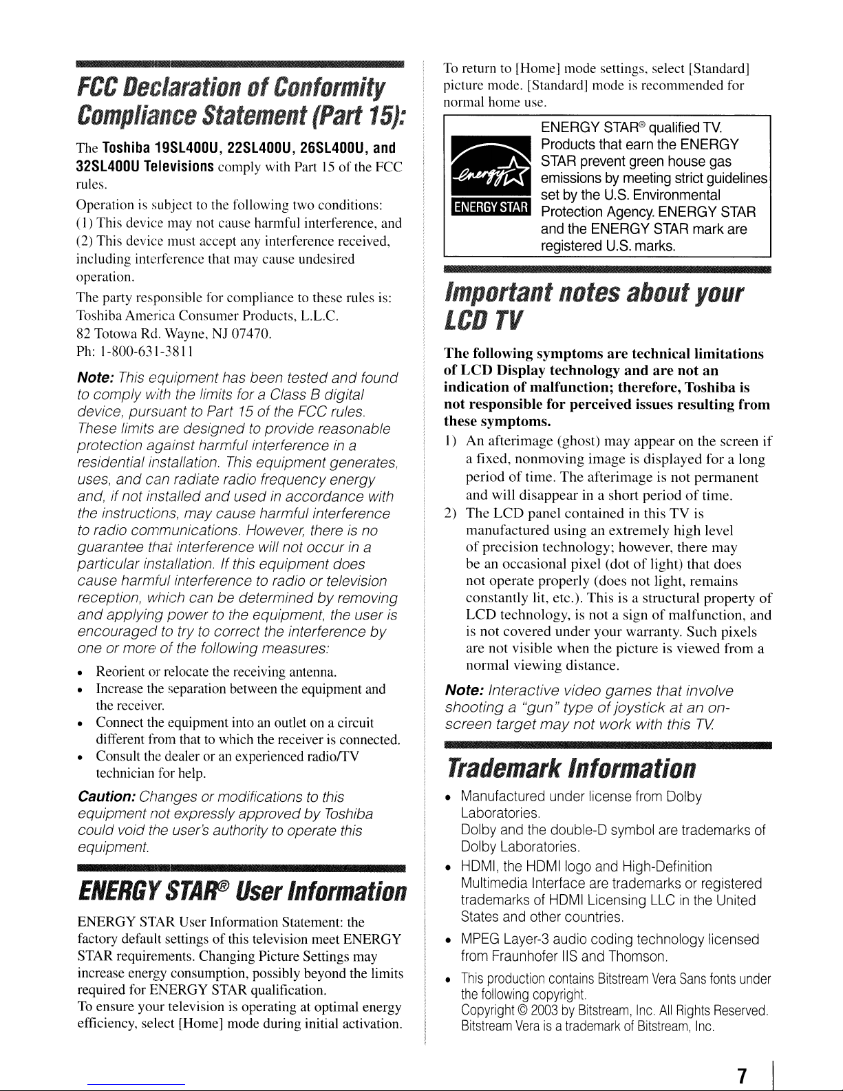
To
return to [Home] mode settings, select [Standard]
picture mode. [Standard] mode is recommended for
normal home use.
ENERGY
Products
STAR
emissionsbymeeting
setbythe
Protection
and
registered
Important
LCD
The
of
indicationofmalfunction; therefore, Toshiba is
not
these symptoms.
I)
2)
Note: Interactive video
shootinga"gun"
screen target
TV
following
LCD
Display technology
responsible for perceived issues resulting from
An
afterimage (ghost)
a fixed,
period
and will
The
manufactured
of
beanoccasional
not
constantly lit, etc.).
LCD
is not
are
normal
nonmoving
of
LCD
precision technology; however, there
operate
technology, is not a signofmalfunction, and
covered
not
visible when the picture is viewed from a
viewing
notes
symptoms
time.
The
disappear
panel
using
properly (does
under
may
Trademark
STAR®
that
prevent
U.S.
Agency.
the
ENERGY
U.S.
are
may
image is displayed for a long
afterimage is not
in a short periodoftime.
contained
an extremely high level
pixel (dotoflight)
This
your
distance.
games
typeofjoystickatan
not
work with this
qualified
earn
the
ENERGY
green
house
strict
Environmental
ENERGY
STAR
mark
marks.
about
technical limitations
and
are
appearonthe screen
in this
not
is a structural property
warranty.
your
not
permanent
TV
is
that
light,
remains
Such
that involve
TV
Information
TV.
gas
guidelines
STAR
are
an
may
does
pixels
on-
if
of
Caution: Changes ormodifications
equipment not expresslyapprovedbyToshiba
could void the user's authoritytooperate this
equipment.
ENERGtrSTAr
ENERGY STAR User Information Statement: the
factory default settings
STAR requirements. Changing Picture Settings may
increase energy consumption, possibly beyond the limits
required for ENERGY STAR qualification.
To ensure your television is operating at optimal energy
efficiency, select [Home] mode during initial activation.
User
of
this television meet ENERGY
to
this
Information
•
Manufactured
Laboratories.
Dolby
and
Dolby
Laboratories.
•
HDMI,
Multimedia Interface
trademarksofHDMI
States
•
MPEG
from
•
This
the
Copyright©2003byBitstream,
Bitstream
the
and
Layer-3
Fraunhofer
production
following
under
the
double-D
HDMIIogo
other
audio
contains
copyright.
Veraisa
license
and
are
Licensing
countries.
coding technology licensed
liS
and
trademarkofBitstream,
from
Dolby
symbol
trademarksorregistered
Thomson.
Bitstream
are
trademarks
High-Definition
LLCinthe
Vera
Sans
Inc.
All
Rights
Inc.
United
fonts
Reserved.
of
under
7
Contents
Important
Installation,
Chapter1:Introduction
Chapter2:Connecting
Chapter3:Using
Chapter4:Menu
Chapter5:Settingupyour
Chapter6:Using
Safety
Instructions
Care,
and
Service
Featurcsofyour
Ovcrvicwofsteps
and
TV
front
TV
back
Overviewofcable
Ahllutthe connection illustrations.......... IJ
ConnectingaVCR
ConncctingaDVD
(component
ConncctinganHDMI'"orDVI
REGZA-L1NKMconnection........ .
Conncctingadigital
Connccting a
Installing
Remotc
Lcarning
Main
menu
Setupllnstallation
Navigating
new
TV....................................
for
installing.
using
your
ncw
TV............... .10
and
side
pancl
controls
panel
cunnectillns.
your
types.
and
antenna.
player
vidco).aVCR.ora satellite
audio
the
control
about
layout
the
personal
remote
computcr
the
remote
control
effective
the
remote
layout
and
menu
layout
menu
system... .n
TV
with
devicctothc
systcm
control
batteries...
range
controL
navigation
selling
up.
and
conncctions
CablcTVor
ColorStrcam'"'
(PC)....
Camcordcr
rcceiver
HDMI
input
. IX
.................23
TV
Initial
Setup
Selecting
Configuring
Programming
SellingAVInput
Setting
Viewing
Selling
Viewing
Selecting
Labeling
Tuning
Scrolling
Using
Selecting
Using
Adjusting
Using
Adjusting
the
menu
language
the
antenna
input
ANT/CABLE
Programming
Setting
channel
the
the
the
the
the
the
channels
Tuning
channels
Setting
the
Tuningtothe
Tuningtoa
(programmedorunprogrammed)
Switching
Selecting
the
(TheaterWide2and3only)
the
auto
the
the
FREEZE
Selecting
Adjusting
the
closed
Base
closed
DigitalCCSettings
CC
Selector.............
terminal............
channels
channels
skip
mode..
HDMl"'
audio
digital
signal
time
zone....
system
the
video
input
video
input
using
Channel
next
specific
between
the
picture
TheaterWide'"
aspect
cinema
the
picture
the
picture
the
picture
caption
captions
the
audio
into
automatically.....
status
TV's
sourcetoview
sources
the
Tuning
programmed
channel
two
size
ratio
mode
feature
mode
quality...........
..
source
the
TV's
mode
meter
features
Channel
Mode...............
channels
picturc
feature
mode
.
for
channel
Browser'"
channel
using
the
..
memory
..
..
SurfLock'"
Muting
the
3
3
9
..
9
II
..
12
13
..
1:1
.......
14
15
16
17
IX
20
..
20
..
20
21
22
'YJ
24
24
..
24
24
24
..
24
..
25
26
26
..
27
27
..
27
28
28
28
..
29
29
..
31
:12
32
,32
:12
34
34
35
35
35
35
36
36
36
,37
37
37
Using
Selecting
Adjusting
Selecting
Using
Using
Entering
If
you
Changing
BlockingTVprograms
Downloadinganadditional
Locking
Unlocking
Using
Using
Using
Using
Selling
Using
Using
To
To
Viewing
Single
Slideshow.................
Playing
During
Viewing
Selling
Automatic
No
Signal
Using
REGZA-L1NK~)
REGZA-L1NK
VOLUME
Other
DisplayingTVstatus
Understanding
Understanding
Chapter7:Using
Using
Using
Using
Selecting
Using
Using
Using
Chapter8:TroUbleshooting
Generaltroubleshooting
Chapter9:Appendix
Specifications
Acceptable
Limilecl
Limited
sound...........
the
digital
audio
sekct()l
stereo/SAP
the
the
the
Dolby")
the
Locks
the
cannot
your
by
rating
f(Jr
blockingTVprograms
channels
prugrams
the
input
the
GameTimet.«)....................................
the
control
thePCsellings feature.................................
thePCAudio........... ...-l3
the
Media
the
Media
select
the
open
the
Media
photo
View.............
music
playback.....
photo
the
sleep
Power
Power
REGZA-L1NK".
and
REGZA-LlNK®
the
advanced
Dynamic
the
static
the
CableCleaf"
MPEG
the
Game
signal
United
Canadian
Televisions
hroadcasts
audio
ljuality........
optical
audio
Digital
menu
...............W
PIN
code....
rememhcr
PIN
code
(V-Chip)
temporarily
lock
feature..................
panel
Player............................................44
Player
Auto
Start
Player
lilcs
..
Jiles
..
tiles
with
timer..........................
Down.........................................
Down..
playback
C
input
source
"
MUTE
information
the
auto
power
the
last
mode
the
TV's
picture
Contrasl...
gamma
color
temperature
digital
noise
reduction............................ .
Mode
formats
States
Wan'anty
Warranty
.........
..
llutput
formal........
Dynamic
your
and
lock
with
function
playing
device
controlsofAudio
functions..............
advanced
sellings
feature
feature
forPCIN
Range
Contrul
PIN
code.
movies
rating
system
and
movies....
feature...............
USB
musie
filesatsame
(DVD
player.
selection........................... .
Receiver
off
feature
memory
fealure...
features
features......
noise
for
reduction
for
Toshiba
..........
and
HDMltenninals
LCD
Televisions
Brand
etc.)
Flat
..
rcaturc
..
..
.....
..
..
..
.
time
..
..
..
control
..
........57
Panel
...'7
..
...'X
...\lei
..
..
..
..
.. ..
..
..A2
.A2
.
..
....
....44
..A5
..AX
..
...A9
....
...51
.
.. ..
37
3X
)X
:19
y)
..
19
.\lel
-I()
-ll
A1
A2
A3
..44
44
45
..45
.45
46
46
47
.47
47
.AX
AX
.4X
49
..
51
..
.52
53
55
50
50
51
51
51
52
52
53
55
56
58
8
Features
The following are just a fewofthe many exciting
features
HD, LCD TV:
Integrated
•
QAM)
converter set--top box (in most cases).
• 1366 x 768 output resolution.
• Two
•
• Digital Audio
•
•
•
•
HDMJ'!"
interfaces I080p input support
One
setofColorStream®
component video inputs
by setting the
(lI:$fo
page 26).
Dolby®
CableClear
page 52).
PCIN(Anallog
pages 18-19).
REGZA-LINK
from the TV remote via HDMI connection(1&
page 48).
Media
to play music files.(1& page 44).
(If
your
of
your new Toshiba widescreen, integrated
digital
eliminates the need for a separate digital
digital, high-definition multimedia
AV
Out
Digital optical output format
lR
' digital picture noise reduction
RGB)
allows controlofexternal devices
Player
allows you to view photo files and
new
tuning
input mode to ColorStream HD
optical audio connection with
computer terminal
TV
(8VSB ATSC
(1&
page 16).
HD
high-resolution
(1&
page 15). Thisisused
(1&
and
page 39).
(1&
(1&
9
Overviewofsteps
setting
Follow these steps to set up
up,
and
for
using
your
installing,
your
TV
new
and begin using
its many exciting features.
Carefully
1
care. and service information. Keep this manual
for future reference.
Observe
2
for the TV:
read the important safety. installation.
the following
when
choosing
a location
TV
10
Program
(U!;l page 24).
11
For details on using the
Chapters
12
For
Chapter
13
For technical specifications
information. see
14 Enjoy
channels
6 and 7.
help. refer to the
8.
Chapter
your
new
TV!
into the
TV's
channel
TV's
features. see
Troubleshooting
and
warranty
9.
memory
Guide.
• Read
• Place the
• Place the
•
3
Do
have
4
BEFORE
learn the functions
controls
5
Connect
(U11'
"Important
(U!;l page 7).
TVonthe floorora sturdy, level.
stable surface that can
Secure
unit.
immovable
reflect on the screen.
Place
objects
ventilation may
damage
IS
NOT
WARRANTY.
not plug in any
connected
pages 13-19).
the
structure
TVina location
theTVfar
to allow
the
TV
COVERED
all
connecting
(1&
pages
your
other
6 Install the batteries
20).
notes about
TV
to a wall. pillar,orother
(IGI~
enough
proper
cause
overheating, which will
THIS
TYPE
UNDER
power
cables
cablesordevices
of
the
I 1-12).
electronic
in
the
your
support
ventilation. Inadequate
TV's
the
weightofthe
page
4).
where
from walls and
cords
and
remote
light
OF
DAMAGE
THE
until
devicestoyour
connections
device(s) to the
control
LCD
TV"
docs
other
TOSHIBA
AFTER
to the TV.
and
(I@'
not
you
TV
TV
page
7
See
"Learning
21
) for an overview
control.
8
AFTER
in the
power
Then
press
remote
responding
orTVcontrol panel
otToron,
seconds
9
See
overviewofnavigating the
(UE
I
10
control to turnonthe
"Menu
page
about
the
remote
of
the buttons on the remote
connecting
cords
POWER
to the
please
then re-plug to try again.
layout
22).
all
cables
for
your
TV
on theTVcontrol panel
TVIfthe
controls
unplug
and
on the remote control
and
you
cannot
the
power
navigation"
TV's
control"
and devices, plug
and
menu
(~'
other
devices.
TV
stops
turn the
cords
few
foraquick
system
page
or
TV
TV
front
Model 26SL400Uisusedinthis manual for illustration purposes.
and
side
panel
controls
and
connections
-I.·'--;1
3-illl
4-01
5
I-JvJ
·.~
i~J'11
I
I!..
'0
Left
side
panel
,
I
,
!I.
11
."
...•....•..•.•
Ilv~E]D-g
I!
M'''U
II
6-
7-IO~_1
1
1
0:
i
INf'UT
I
I
-10
L0~~JJ
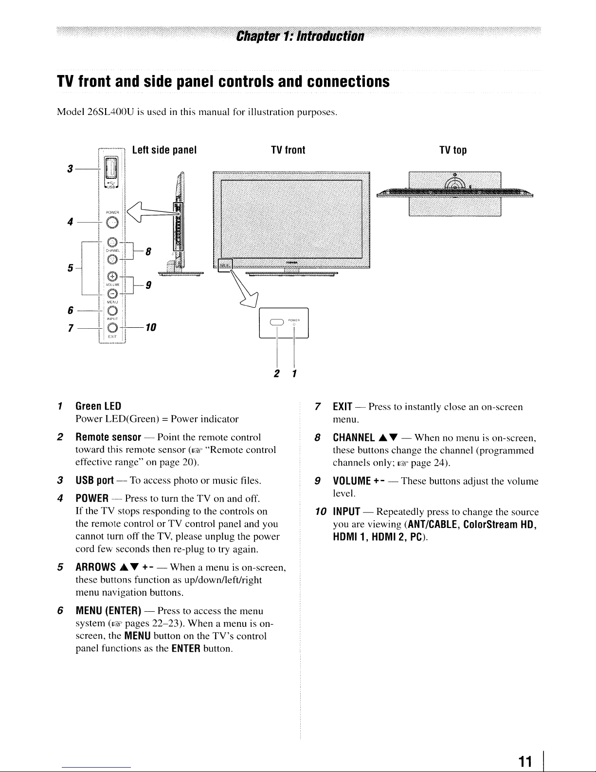
Green
LED
Power LED(Green) = Power indicator
TV
2 1
front
TV
top
7
EXIT
- Press to instantly close
menu.
an
on-screen
2
Remote
toward this remote sensor
effective range" on page 20).
3
USB
4
POWER
If
the remote control or
cannot turn off the
cord few seconds then re-plug to try again.
5 ARROWS.T
these buttons function as up/downlleft/right
menu navigation buttons.
6
MENU
system
screen, the
panel functions as the
sensor
port
--
the TV stops responding to the controls on
(ENTER)
(D~~
- Point the remote control
(I@F
"Remote control
--
To
access photo or music files.
Press to turn the TV on and off.
TV
control panel and you
TV,
please unplug the power
+-
- When a menu is on-screen,
- Press to access the menu
pages 22-23). When a menu is on-
MENU
button on the
ENTER
TV's
button.
control
8 CHANNEL.T - When no menu
these buttons change the channel (programmed
channels only;
9
VOLUME
level.
10
INPUT
you are viewing
HOMI1,
- Repeatedly press to change the source
I@F page 24).
+-
- These buttons adjust the volume
(ANT/CABLE,
HOMI
2,
PC).
is
ColorStream
on-screen,
HO,
11
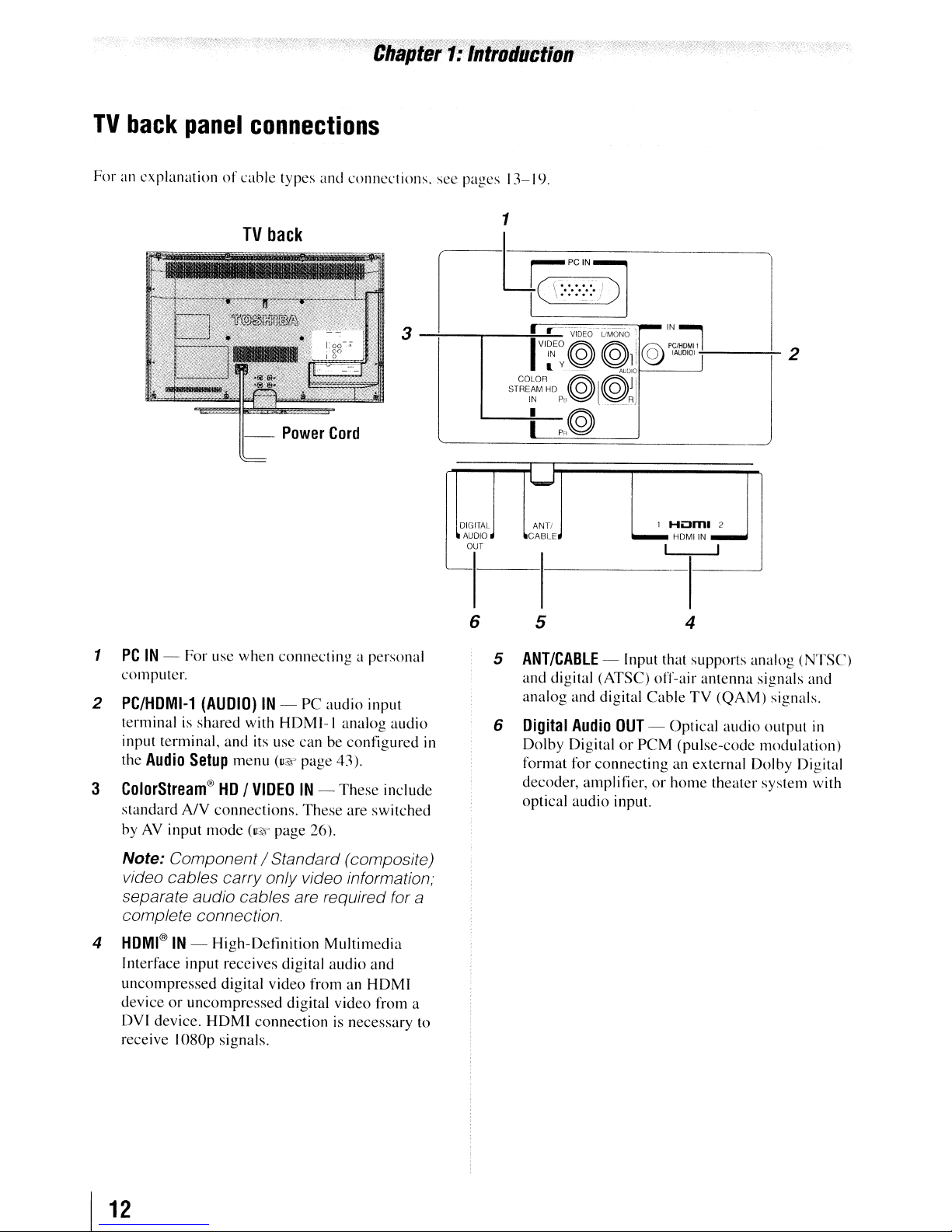
TV
For an
back
panel
explanationofcable
connections
TV
types and
back
connections.
see pages 13-19.
1
1
PCIN-
computer.
2
PC/HDMI-1
terminal is
input terminal,
the
Audio
3
ColorStream®HD/
standard
byAVinput
For
usc
when
(AUDIO)IN- PC
shared
Setup
with
and
its use can be
menu
VIDEOIN-
AN
connections.
mode
(IQ"
connecting
audio
HDMI-l
(v~
page 43).
These
page
26).
a personal
input
analog
eontigured
These
include
are
switched
i-trcr·::·:::·/
I
3
rr
.
VIDEO
)]
UMONO'
r::@~D11
audio
DIGITAL
AUDIO
OUT
'---1----1--------1
6 5
in
COLOR
STR~~M
5
6
@@JI
HD?il
0 l
()_RJ
I
?R@
I
ANTI
CABLE
ANT/CABLE
and
digital (ATSC) off-air
analog
Digital
Dolby
format for
decoder, amplifier,
optical
- Input that supports analog
and
digital
Audio
DigitalorPCM
connecting
audio
,....IN:l
PClHOM11
@
tAUOIO)
1
Hi:J~12
HDMIIN
I I
Cable
OUT
- Optical
an external Dolby Digital
or
home
input.
I
4
antenna
TV
(QAM)
audio
(pulse-code
theater
I
2
(NTSC)
signals and
signals.
output
modulation)
system
in
with
Note: Component / Standard (composite)
video cables carry only video information;
separate audio cables are required for a
complete connection.
4
HDMI®IN-
Interface input receives digital
uncompressed
deviceoruncompressed
DVI device.
receive
I
12
High-Definition
digital
HDMI
I080p
signals.
video
from an
digital
connectionisnecessary
Multimedia
audio
and
HDMI
video
from a
to
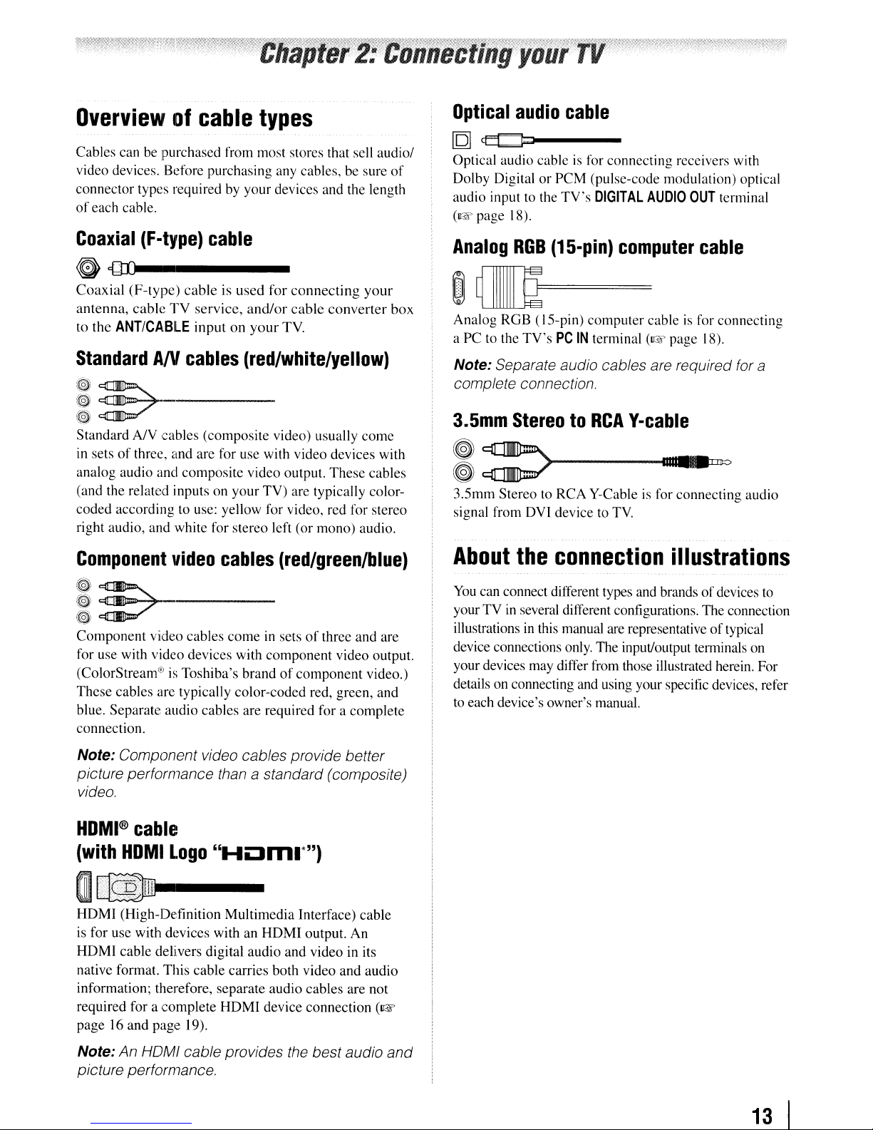
Overviewofcable
Cables can be purchased from most stores that sell audio/
video devices. Before purchasing any cables, be sure
connector types required by your devices and the length
of
each cable.
types
of
Optical
[Q]
Optical audio cableisfor connecting receivers with
Dolby DigitalorPCM (pulse-code modulation) optical
audio input to the
(~page
audio
~I----
TV's
18).
cable
DIGITAL
AUDIO
OUT
terminal
Coaxial
G
Coaxial
antenna,
to the
Standard
~
~~
~
Standard
in setsofthree, and are for use with video devices with
analog audio and composite video output.
(and the related inputs on your
coded according to use: yellow for video, red for stereo
right audio, and white for stereo left (or mono) audio.
Component
~
~E7
~
Component video cables
for use with video devices with component video output.
(ColorStream'EIisToshiba's brandofcomponent
These cables are typically color-coded red, green, and
blue. Separate audio cables are required for a complete
connection.
(F-type)
cable
{1ll-------
(F-type)
cable
ANTICABLE
AN
cableisused
TV
AN
cables
service,
inputonyour
for
connecting
and/or
cable
TV.
(red/white/yellow)
._-----
cables (composite video) usually
TV)
are typically color-
video
,-----
cables
comeinsetsofthree and are
(red/green/blue)
your
converter
come
These
cables
video.)
box
Analog
RGB
(15-pin)
computer
cable
~W==
Analog RGB (IS-pin) computer cableisfor connecting
a PC to the
Note: Separate audio cables are required for a
complete connection.
3.5mm
I
3.Smm
signal from DVI device to
About
You
yourTVin
illustrationsinthis manual are representativeoftypical
device connections only. The input/output terminals on
your devices may differ from those illustrated herein. For
details on connecting and using your specific devices, refer
to each device's owner's manual.
TV's
PC
IN
terminal
StereotoRCA
:>
Stereo to
can connect different types and brandsofdevices
RCA
Y-Cableisfor connecting audio
the
connection
several different configurations. The connection
(~page
Y-cable
TV.
18).
11I1
,11
••
'0
illustrations
to
Note: Component video cables provide better
picture performance than
video.
HOMI®
(with
cable
HOMI
Logo
a standard (composite)
"HOm.·")
O~
HDMI (High-Definition Multimedia Interface) cable
is for use with devices with an HDMI output. An
HDMI
native format. This cable carries both video and audio
information; therefore, separate audio cables are not
required for a complete
page16and page 19).
Note: An HOMI cable provides the best audio and
picture performance.
cable delivers digital audio and video in its
HDMI
device connection
(~
13
I
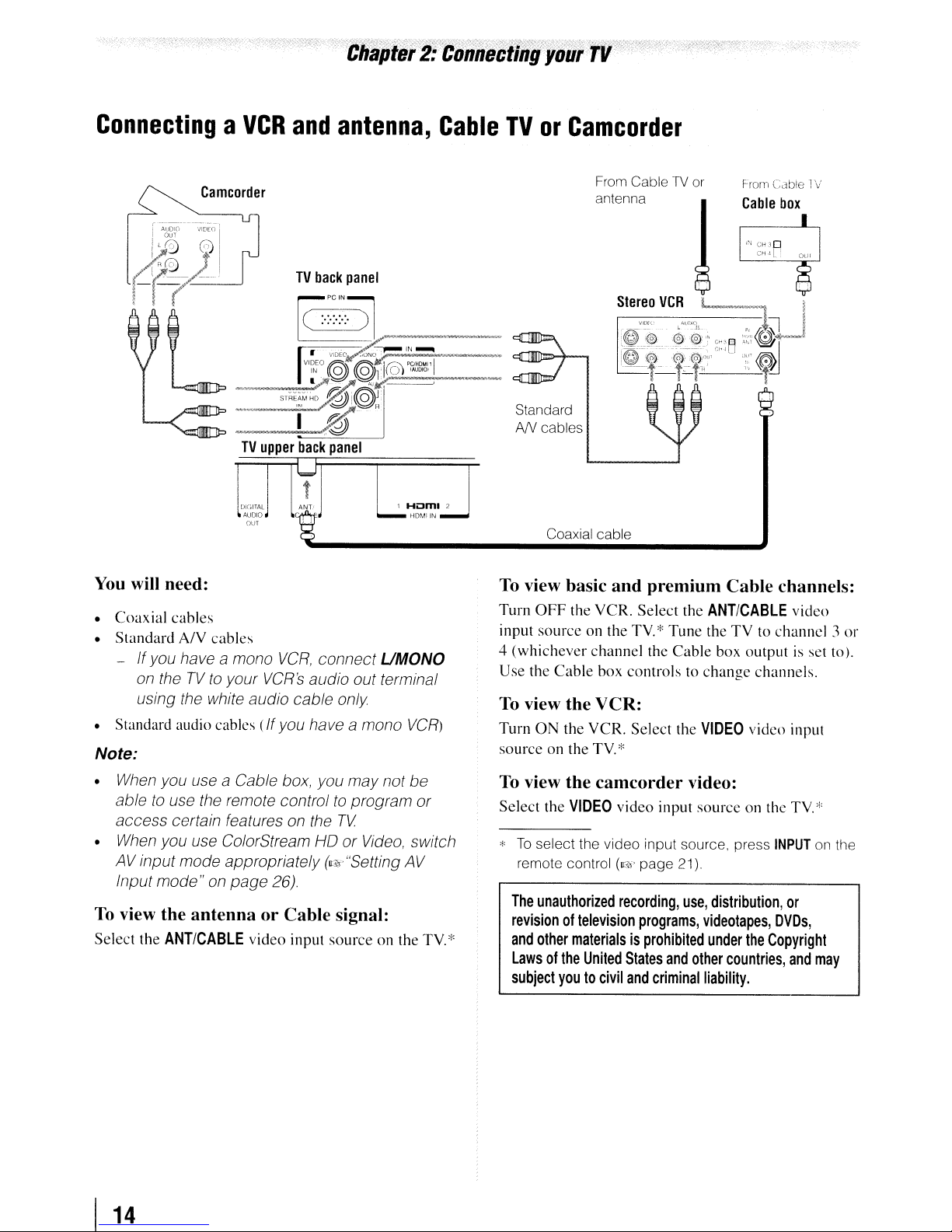
ConnectingaVCR
Camcorder
and
antenna,
Cable
TVorCamcorder
From
CableTVor
antenna
Standard
AN
cables
Coaxial cable
From
Cable
Cable 1V
box
You
will need:
•
Coaxial
• Standard A/V cables
- Ifyou have
• Standard audio cables
Note:
• When you use a Cable box, you
able to use the remote controltoprogram
access
• When you use ColorStream HO or Video, switch
AVinput
Input
To
view the antenna or Cable signal:
Select the
cables
a mono
on theTVto
using the white audio cable only
certain features on the
mode"onpage
ANTICABLE
your
mode
appropriately (Vs."Setting AV
VCR,
connect UMONO
VCR's
audio out terminal
(If
you have a mono
may
TV
26).
video input source on the
not
VCR)
be
or
TV*
To
view basic and premium Cable channels:
Turn
OFF
the VCR. Select the
source
input
4 (whichever channel the
Use the
To
view the VCR:
Turn
ON
source on the
To
view the camcorder video:
Select the
*
To
select the video input source, press
remote control
The
unauthorized
revisionoftelevision
and
other
Lawsofthe
subject
on the
TV*
Cable
box controls to
the
VCR.
Select the
TV
*
VIDEO
video input
(v:<)'
page 21).
recording,
programs,
materialsisprohibited
United
States
youtocivil
and
criminal
ANT/CABLE
Tune the
Cable
change
VIDEO
source
use,
videotapes,
under
and
other
liability.
TV
to channel 3
box output is set to).
channels.
viden input
on theTV*
INPUT
distribution,
or
DVDs,
the
Copyright
countries,
video
and
or
on the
may
I
14
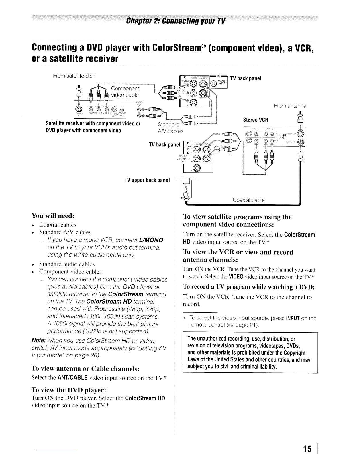
ConnectingaDVD
or
a satellite
receiver
player
with
ColorStream®
(component
video),aVCR,
From satellite dish
Component
TV
You will
•
Coaxial
•
Standard
- Ifyou have a mono
•
Standard
•
Component
-
Note: When you use ColorStream HO
switch AV input
Input
To view
Select
ne{~d:
cables
A/V
cables
VCR,
connect
on theTVto
using the white audio cable only
audio
You
can connect the component video cables
(plus audio cables) from the
satellite receiver
on the
can be
and
Interlaced
A
10BOi
performance
mode"onpage
antenna
the
ANTICABLE
your
VCR's
cables
video
cables
to
TV
The
ColorStream
used
with Progressive
(4BOi,
signal will provide the best picture
(10BOpisnot supported).
mode
appropriately
26).
or
Cable
video
audio out terminal
OVO
the
ColorStream
HD terminal
10BOO
scan systems.
channels:
input
sourceonthe
upper
back
UMONO
player or
terminal
(4BOp,
720p)
or
Video,
(c:.<Y·"Setting
panel
AV
TV,'"
TV
back
panel
Coaxial cable
To view satellite
component
Turnonthe
HD
video
To view
antenna
Turn ON the VCR. Tune the VCR to the channel you want
to watch. Select the
To
record a TV program while watching a
Turn
record.
."Toselect the video input source, press
remote control
The
revisionoftelevision
and
Lawsofthe
subject
satellite
input
the
channels:
ON
the
unauthorized
other
materialsisprohibited
United
youtocivil
programs
using
video connections:
receiver.
sourceonthe
VCRorview
VIDEO
VCR.
Tune
(~?!'
page
recording,
programs,
States
and
Select
TV.
and
video input source on the
the
VCRtothe
21)
use,
distribution,
videotapes,
under
and
other
criminal
liability.
the
the
ColorStream
'"
record
the
countries,
TV."'
DVD:
channel
INPUT
on the
or
DVDs,
Copyright
and
may
to
To view
Turn
video
0
input
the
the
DVD
DVD
sourceonthe
player:
player.
Select
TV.
the
'"
ColorStream
HD
15
I
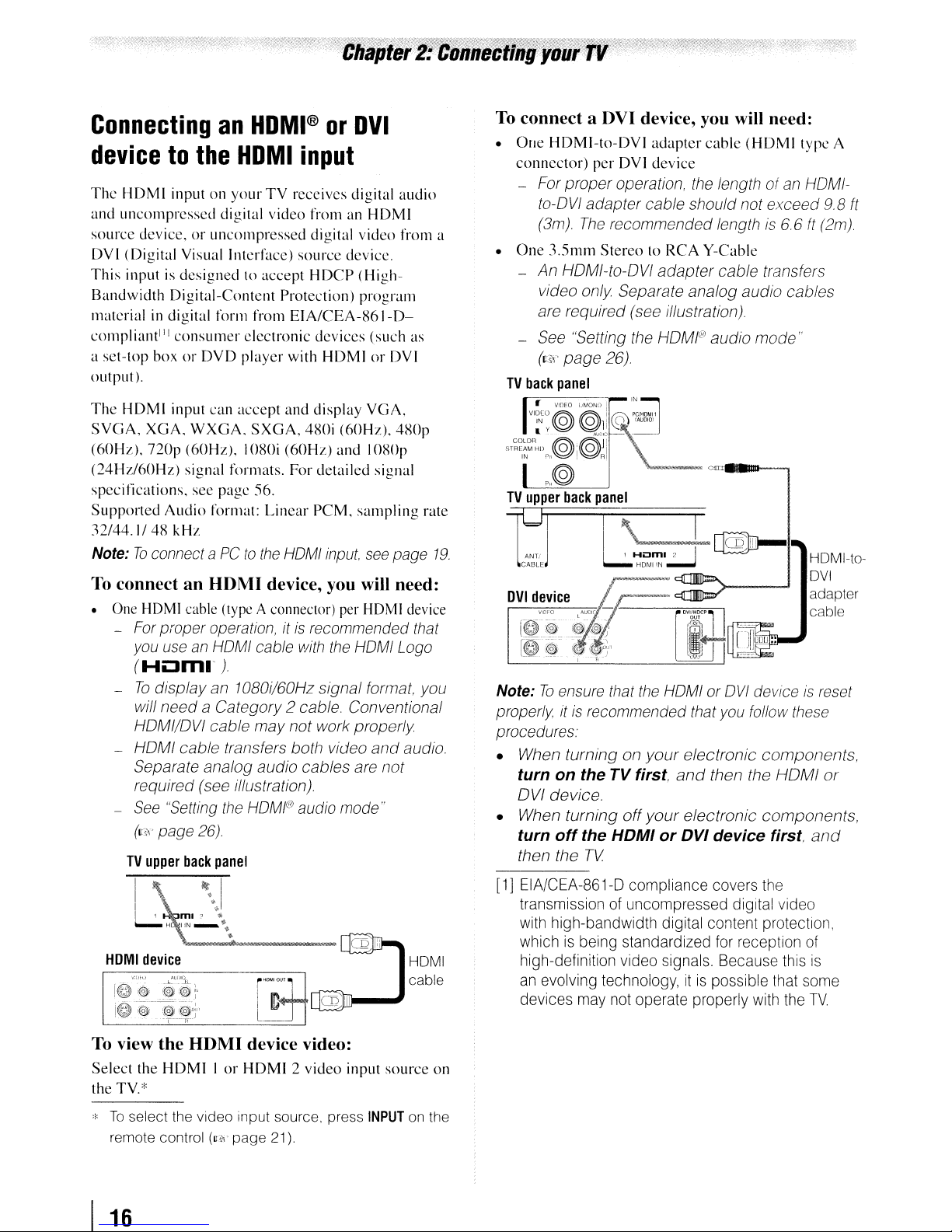
ConnectinganHDMI®orDVI
devicetothe
Thc
HDMI
and
uncompressed
source
DVI
This
Bandwidth
materialindigital form from
compli~\I1tIJl
a
set-top
output
The
HDMI
SYGA,
(60Hz),
(24Hz/60Hz)
specitications.
Supported
32/44.1/48
Note:Toconnect aPCto
To connectanHOMI
• One HDMI cable (type A connector) per HDMI device
- For proper operation,
-
- HOM I
-
inputonyour
device,oruncoll1pressed digital
(Digital
inputisdesignedtoaccept
you use an HOMI cable with the HOMI Logo
(H~ml'
Yisuallntcrface)
Digital-Content
consumer
boxorDYD
).
input
XGA.
WXGA.
nop
(60Hz).
signal
Audio
kHz
To
display
will
needaCategory
HDMI/DVI
cable
Separate analog
required (see illustration)
See
"Setting the
(11<\'
page 26)
HDMI
TV
digital
can
see
pagc
format:
)
an 10BOi/60Hz
cable
video
Protection)
EIA/CEA-S61-D-
electronic
player
with
accept
formats.
SXGA,
IOSOi
56.
Linear
the
and
(60Hz)
For
HOMI
device, you will need:
it
2 cable. Conventional
may
not
transfers both video
audio
HOMI@
input
receives
source
is recommended that
cables
audio mode"
digital
fromanHDMI
video
device.
HDCP
480i
(Highprogram
devices
HDMIorDVI
display
detailed
PCM.
signal
work
(60Hz).
and
input,
(such
YGA,
IOSOp
signal
sampling
see
format, you
properly
and
are
not
audio
from
as
480p
page
audio.
rate
a
19.
To connect a OVI device, you will need:
•
One
HDMI-to-DVI
connector)
- For
to-DVI
(3m)
•
One
-
An
video
are required (see illustration)
- See "Setting the HDMI®
(cS'<'
TV
back
r-=---~
VI~[O
IN
y@
ST~~~~R:1l
IN
rll~~RI
per
proper
adapter
The
3.5mm
StereotoRCA
HOMI-to-OVI
only
page
26)
panel
VIDEO
__
LJMONDiPClHDMll
@li
t@.',@Jl
p,,@
TV
upper
back
panel
I \
ANTI J 1
CABLE
tJ
Note:Toensure that
properly
procedures.
• When
turn
on
OVI
device.
• When
turn
off
then the
I
it
is recommended that you follow these
turningonyour
the
turning
the
TV
adapter
DVl
device
operation, the length of an HDMI-
cable should not
recommended length is
adapter
Separate analog
IN
@
IAUOIO'
\~
-~
cable
Y-Cable
cable
audio
audio
(HDMI
exceed
transfers
mode
6.
6
cables
=-..--.
_nI@D-
Hom.
2 I
HDM!
IN
~
the
HOMI or
TV first,
off
and
your
HDMIorDVI
OVI
efectronic
then the
electronic
device
deviceisreset
components,
HOMI
components,
first.
type
9.B
ft
(2m)
,.
HOMI-toDVI
adapter
cable
or
and
A
ft
HOMI
device
vm-,:
I@
:@
To view
Select
the TV.*
*
To
remote control
I
16
......L-'lI~)
@'~i@;~
-ij.
tW
l@y+'
".
--'l---~-
the
HOM)
the
HDMIIor
select the video Input source, press
device video:
HDMI2video
(U!i\'
page
21).
input
source
INPUT
HOMI
cable
on
on the
[1] EIA/CEA-861-D compliance covers the
transmission of uncompressed digital video
with high-bandwidth digital content protection,
whichisbeing standardized for reception of
high-definition video signals. Because this
an evolving technology,itis
devices may not operate properly with the
possible that some
is
TV

REGZA·LlNK®
You
can control the basic functionsofconnected audio/video devices using the
connect a REGZA-LINK compatible audio receiver
operations, see pages 48-49.
connection
or
playback device. For an explanationofsetup and
TV
upper
back
panel
Hum,1
•
HDMIIN
•
I
TV's
remote control if you
Audio
receiver
Playback
(REGZA-liNK
To connectanAudio Receiver
device
DVD
player,etc.)
and
Playback
Devices, you will need:
• HDMf cables
Note:
•
If
several devices are connected, REGZA-LINK
feature may not operate properly.
• For proper operation, it is recommended that you
use HDMI cables with the HDMI Logo
(Hi:3m
..
(~~
).
page
13)
g
g
Playback
(REGZA-liNK
device
DVD
player,etc.)
~----I(iii"lf~CDbnfD-l
Before controlling
• After completing the above connections, set the
REGZA-liNK
49).
The
•
•
• This feature is limited to models incorporating
connected devices must also be set. For
details, see the operation manual for each device.
The
REGZA-LINK
technology as regulated by the HDMI standard.
Toshiba's REGZA-LINK. However, Toshiba
liable for those operations. Refer
instruction manuals for compatibility information.
the
device(s):
Setup
menu as you desire
feature uses the CEC
(w
to
the individual
page
is
not
Note:
depending
This feature
may
not work
on the devices that are connected.
properly
17
I
Chapter
2:
Connecting
your
TV
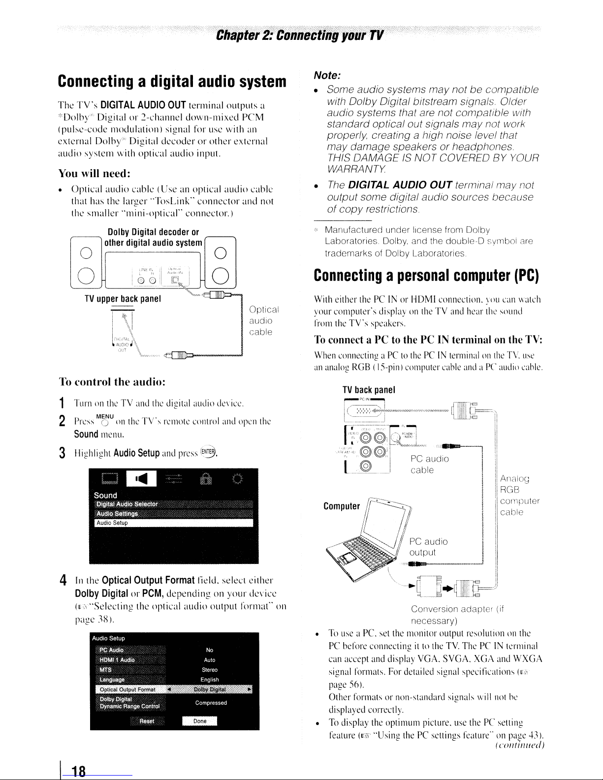
Connectingadigital
The
TV's
DIGITAL
*Dolby"" Digital
(pulse-code modulation) signal for usc with
external Dolby"" Digital decoder or other external
audio system with optical audio input.
You
will need:
• Optical audio cable (Use an optical audio cable
that has the larger "TosLink" connector and not
the smaller "mini-optical" connector.)
other
Dolby
AUDIO
or
Digital
digital
OUT
2-channel down-mixed reM
decoder
audio
audio
terminal outputs a
or
r--_,
system
system
an
o
o
Optical
audiO
cable
To
control the audio:
Note:
• Some audio systems
with Dolby Digital bitstream signals. Older
audio systems that are not compatible with
standard optical out signals
properly, creating
may
damage speakers or headphones.
THIS DAMAGE
WARRANTY
•
The
DIGITAL
output some digital audio sources because
of
copy
Manufactured under license from Dolby
Laboratories. Dolby. and the double-D symbol are
trademarks of Dolby Laboratories
AUDIO
restrictions
Connectingapersonal
With
either
thePCINorHDMI
your computer's displayontheTVand
from
the
TV's speakers.
To
connect aPCto
When
connectingaPCtothePCIN
an
analog
RGB(IS-pin)
may
not be compatible
may
not work
a high noise level that
IS
NOT COVERED BY YOUR
OUT
terminal may not
computer
connection.
the
PCINterminalonthe
terminalonthe
computer
cable
hear
and
aPCaudio
you
the
sound
(PC)
can
TV.
watch
TV:
use
cable.
1
TurnontheTVand
· ..
MENU I T\"
less 0
P
2
Sound
3 Highlight
4
[n
Dolby
(us"Selecting the optical audio output format" on
page
ont1e
mcnu.
Audio
the
Optical
DigitalorPCM,
3X).
the
. s
Setup
Output
digital
audio
dc\icc.
remote
control
and
press
Format
depending on your device
and
open
(E~.
field. select either
the
Conversion adapter (if
necessary)
•
To
use
a Pc.
set
the
monitor output resolutiononthe
PC
before connectingitto
can
accept
and
display
signal
formats.
page
56).
Other formatsornon-standard signals
displayed correctly.
•
To
display
feature
(1r51
For
thc
optimulll picture.
"Using
the
VGA.
detailed
thePCsettings
signal
TV.
ThePCIN
SVGA.
XGA
specifications (Ui
will
use
thePCsetting
featurc"onpage
terminal
and
WXGA
not
he
(
coll/illl/cd)
1
43).
I
18
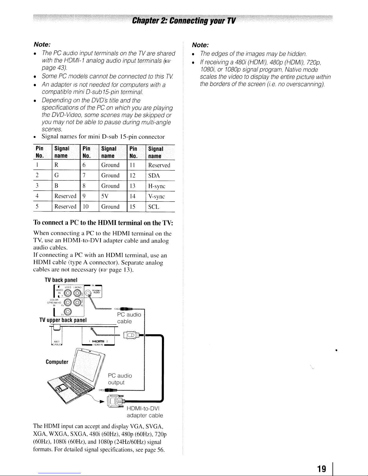
Note:
•
The
PC audio input terminals
with
the
HDMI-1
page 43)
Some
•
•
• Dependingonthe
• Signal names for mini D-sub 15-pin connector
PC models cannot be connected
An
adapterISnot needed
compatible mini D-sub
specifications of
the
DVD-Video,
you
may
not
scenes.
analog audio input terminals
DVD's
thePCon
some
scenes
be abletopause during multi-angle
for
15-pin
title
on
theTVare
computers
terminal.
and
the
which
you
are
maybeskipped
shared
to
this
with
playing
(1&
TV
a
or
Note:
•
The
edges of
•Ifreceiving a
1080i,or1080p
scales
the
the
videotodisplay
borders of
the
480i
the
images
(HOM/),
signal
screen
maybehidden.
480p
(HDMI),
program,
(i.e.nooverscanning).
the
Native
entire
mode
picture
720p,
within
II
12
13
14
15
ud
Signal····
name
Reserved
SDA
H-sync
V-sync
SCL
TV:
-io'
Pin
No.
I
2
3
4
5
To
When connecting a PC to the HDMI terminal on the
TV,
audio cables.
If connecting a PC with
HDMI cable (type A connector). Separate analog
cables are not necessary
signal
name
R 6 Ground
G
B
Reserved
Reserved
Pin
No.
7
9
-
connect aPCto
useanHDMI-to-DVI adapter cable and analog
TV
back
panel
_':"-:=--
"~.i:
@
@ll
sT~~~%~~~~@)@ll
I
,,@=p·C·alD-
TV
upper
back
panel
Signal
name
Ground
8
.
Ground
5V
10
Ground
the
HDMI
an
(1&
IN
cs~
'f.n~,'
.........
terminalonthe
HDMI terminal, use an
page 13).
L
cable
Pin
No.
\
1
can
Hii:3m12
HOt""1
IN
..:.-J
accept
and
480i
(60Hz),
and
I080p (24Hz/60Hz)
ANTI
CABLE
Computer
The
HDMI
input
XGA,
WXGA,
(60Hz),
formats.
SXGA,
1080i
(60Hz),
For
detailed signal specifications,
~I-~
I
PC audio
output
display
480p
VGA,
(60Hz),
see
SVGA,
nop
signal
page
56.
19
•
I
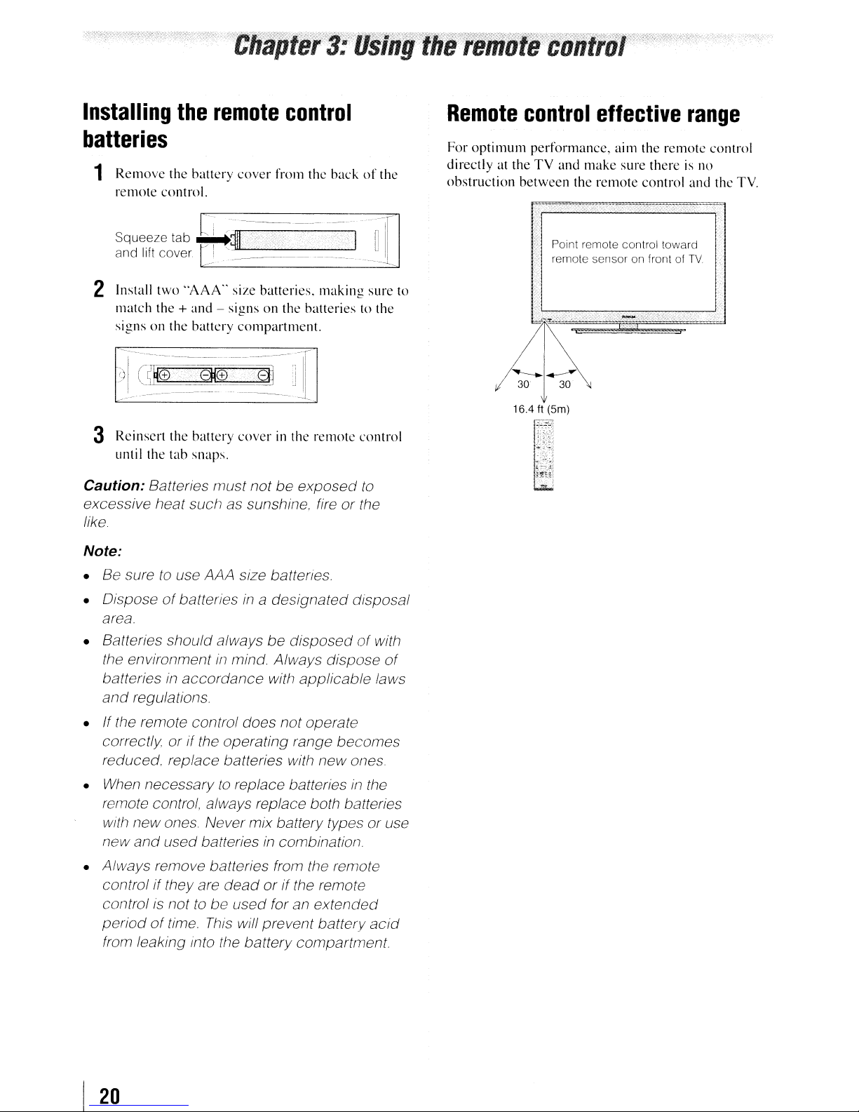
Installing
the
remote
control
Remote
control
effective
range
batteries
1
Remove
remote
Squee,e
and
2 Install
match
signs
3 Rei nscrt
until the
Caution: Batteries must not be exposed
excessive heat such as sunshine. fire or the
like
the
battery
control.
tab
11ft
cover
two
'AAA"
the+and-signsonthe
on the
battery
the
battery
tab
snaps.
cover
~~I~~
~_
__
size batteries,
compartment.
cover
from the
-----
batteries
in the
backofthe
--I
making
remote
to the
control
to
~
TI
__
sure to
For
optimum
directly
obstruction
at the
i~
performance,
TV
and
between
'. Point remote control toward
remote sensor on front
16.4 ft (5m)
t~1~
"'0"';,
..;.~..
.
the
make
remote
aim the
sure
control
I
~
remote
there
of
is no
and
TV
control
the TV.
Note:
• Be sure
• Dispose
area.
• Batteries should always be
the environment
batteriesinaccordance with applicable laws
and
• If the remote control does not operate
correctly or if the operating range becomes
reduced. replace batteries with new ones
When
•
remote control, always replace both batteries
with new ones. Never mixbattery types or use
new
• Always remove batteries from the remote
control
control
periodoftime.
from leaking into the battery compartment
to
use AAA size battertes.
of
batteries
regulations.
necessarytoreplace batteriesinthe
and
used batteriesincombination.
if they are
is
nottobe used for an extended
in
a designated disposal
disposedofwith
in
mind. Always dispose
dead
or
if the remote
This
will prevent battery
of
acid
I
20

Learning
The
buttons used for operating the TV only are
described here.
about
the
remote
control
6
FREEZE
moving
7
Channel
The
(I&'
8
FAV
Channel Browser'"(~page
9
RECALL
(I&'
10
CH
menuison-screen
11
C.
(u:i\'
12
MUTE
13
VOL
14
INFO
details.
15
EXIT
16
ENTER
system.
freezes
the
picture
(I&'
Numbers
~
buttonisusedtotune
page
32)
ortoedit
BROWSER
page
.A.
• cycles
CAPTION
page
reducesorturns
+ - adjusts
displaysTVstatus informationaswellasprogram
when
closes on-screen
activates highlighted
accesses
displaysTVstatus information
49).
through
accesses
36).
the
available (C'§'
picture.
page
(0-9,
(I&'
volume
Press
35).
-/1
00)
directly
digital channels
the
Favorites
the
Favorites
29).
programmed channels
pages
24-25).
the
closed caption
off
the
sound
level.
page
50).
menus.
itemsinthe
againtorestore
tune
channels.
List(~page
Listinthe
(u:i\'
page
37).
main
the
29).
when
menu
no
Note: The error
may
appearifyou
not
that is
1
POWER
on.
illuminated.
2
PIC
available.
turns
the
green
SIZE
cycles through
TheaterWide
(®'
pages
32-34).
3
PIC
MODE
selects
4
INPUT
selem
5
SLEEP
accesses
message
pressakey
theTVon
LED
indicatorontheTVfront
1/2/3.
Full.
the
the
video
the
sleep
"NOT AVAILABLE"
and
off
the
picture sizes:
4:3
HD.
picture
input
timer
mode
source
for a function
When
theTVis
Native
and
(~'
page
(I@.~
page
(lIS"
page
47).
will
be
Natural.
DotbyDot
35).
28).
17
CH
RTN
returnstothe
(~page
18
Arrow
these
see
19
....
Channel
in
(Also
20
MENU
(v,z'
21
STOP
22
PLAY
23
SKIP
24
FF
modetoview
25
EJECT
26
PAUSE
picture: press againtorestart.
27
SKIP
chapter. or locates previous chapters.
28
REW
during
backward.)
32).
buttons
buttons select or adjust programming
....
/~.)
/
~
While
watching
Browser'"
the
channel
see
"Arrow
accesses
pages
22-23).
Stops
the
Begins playback of a
~
Skips
Fast-forwards
the
Eject
the
Press during
~
Skips
Rewinds/reverses
play
modetoview
last
viewed
(.A.
.....
~)
Whenamenuison-screen.
TV.
and
tunetothe
history
(u:~'
page
buttons,")
the
mainTVmenu
tapeorDVD.
forwardtolocate later
the
tape
or DVD,(Press during
picture moving rapidly forward.)
tapeorDVD.
play
or record
backtobeginning ofcurrent
the
the
channelorsource
menus.
these
buttons
open
previous/next
29).
system
tapeorDVD.
DVD
modetopause
tapeorDVD.
picture moving rapidly
(Press
(Also
the
channel
chapters.
play
the
DVD
21
 Loading...