

Page 1
SERVICE MANUAL
LCD Color Television
Print this page
32PB1V1
Updating history
Currently there are no updates available.
Please check back at a later time for any future
updates.
TOSHIBA WEB-ZEUS
Ver. 1.00
>> terms and conditions >> privacy policy
Copyright © 1995-2011 TOSHIBA Corporation, All Rights Reserved.
5
5
6
6
Page 2

Print this page
IMPORTANT NOTICE
WARNING:
You are requested that you shall not modify or alter the information or data provided
herein without prior written consent by Toshiba. Toshiba shall not be liable to anybody
for any damages, losses, expenses or costs, if any, incurred in connection with or as a
result of such modification or alteration.
THE INFORMATION OR DATA HEREIN SHALL BE PROVIDED "AS IS" WITHOUT ANY
WARRANTY OF ANY KIND, EITHER EXPRESS OR IMPLIED WARRANTY OF
MERCHANTABILITY AND FITNESS FOR A PARTICULAR PURPOSE.
Toshiba shall not be liable for any damages, losses, expenses or costs, if any, incurred
in connection with or as a result of use of any information or data provided herein.
TOSHIBA WEB-ZEUS
>> terms and conditions >> privacy policy
Copyright © 1995-2011 TOSHIBA Corporation, All Rights Reserved.
Page 3

Print this page
GREEN PRODUCT PROCUREMENT
The EC is actively promoting the WEEE & RoHS Directives that define standards for recycling
and reuse of Waste Electrical and Electronic Equipment and for the Restriction of the use of
certain Hazardous Substances. From July 1, 2006, the RoHS Directive will prohibit any
marketing of new products containing the restricted substances.
Increasing attention is given to issues related to the global environmental. Toshiba Corporation
recognizes environmental protection as a key management tasks, and is doing its utmost to
enhance and improve the quality and scope of its environmental activities. In line with this,
Toshiba proactively promotes Green Procurement, and seeks to purchase and use products,
parts and materials that have low environmental impacts.
Green procurement of parts is not only confined to manufacture. The same green parts used in
manufacture must also be used as replacement parts.
TOSHIBA WEB-ZEUS
>> terms and conditions >> privacy policy
Copyright © 1995-2011 TOSHIBA Corporation, All Rights Reserved.
Page 4

Print this page
LEAD-FREE SOLDER
This product is manufactured using lead-free solder as a part of a movement within the
consumer products industry at large to be environmentally responsible. Lead-free solder must be
used in the servicing and repair of this product.
WARNING: This product is manufactured using lead free solder.
DO NOT USE LEAD BASED SOLDER TO REPAIR THIS PRODUCT!
The melting temperature of lead-free solder is higher than that of leaded solder by 86ºF to 104ºF
(30ºC to 40ºC). Use of a soldering iron designed for lead-based solders to repair product made
with lead-free solder may result in damage to the component and or PCB being soldered. Great
care should be made to ensure high-quality soldering when servicing this product especially
when soldering large components, through-hole pins, and on PCBs as the level of heat required
to melt lead-free solder is high.
TOSHIBA WEB-ZEUS
>> terms and conditions >> privacy policy
Copyright © 1995-2011 TOSHIBA Corporation, All Rights Reserved.
Page 5
Print this page
SAFETY INSTRUCTION
WARNING: BEFORE SERVICING THIS CHASSIS, READ THE "SAFETY PRECAUTION"
AND "PRODUCT SAFETY NOTICE" INSTRUCTIONS BELOW.
Safety Precaution
WARNING: SERVICING SHOULD NOT BE ATTEMPTED BY ANYONE UNFAMILIAR WITH
THE NECESSARY PRECAUTIONS ON THIS RECEIVER. THE FOLLOWING ARE THE
NECESSARY PRECAUTIONS TO BE OBSERVED BEFORE SERVICING THIS CHASSIS.
1. An isolation transformer should be connected in the power line between the receiver and
the AC line before any service is performed on the receiver.
2. Always disconnect the power plug before any disassembling of the product. It may result in
electrical shock.
3. When replacing a chassis in the cabinet, always be certain that all the protective devices
are put back in place, such as nonmetallic control knobs, insulating covers, shields,
isolation resistor-capacitor network, etc.
4. Always keep tools, components of the product, etc away from the children, These items
may cause injury to children.
5. Depending on the model, use an isolation transformer or wear suitable gloves when
servicing with the power on, and disconnect the power plug to avoid electrical shock when
replacing parts. In some cases, alternating current is also impressed in the chassis, so
electrical shock is possible if the chassis is contacted with the power on.
6. Always use the replacement parts specified for the particular model when making repairs.
The parts used in products require special safety characteristics such as inflammability,
voltage resistance, etc. therefore, use only replacement parts that have these same
characteristics. Use only the specified parts when the mark is indicated in the circuit
diagram or parts list.
7. Parts mounting and routing dressing of wirings should be the same as that used originally.
For safety purposes, insulating materials such as isolation tube or tape are sometimes
used and printed circuit boards are sometimes mounted floating. Also make sure that
wirings is routed and clamped to avoid parts that generate heat and which use high
voltage. Always follow the manufactured wiring routes / dressings.
8. Always ensure that all internal wirings are in accordance before re-assembling the external
casing after a repairing completed. Do not allow internal wiring to be pinched by cabinets,
Page 6
panels, etc. Any error in reassembly or wiring can result in electrical leakage, flame, etc.,
and may be hazardous.
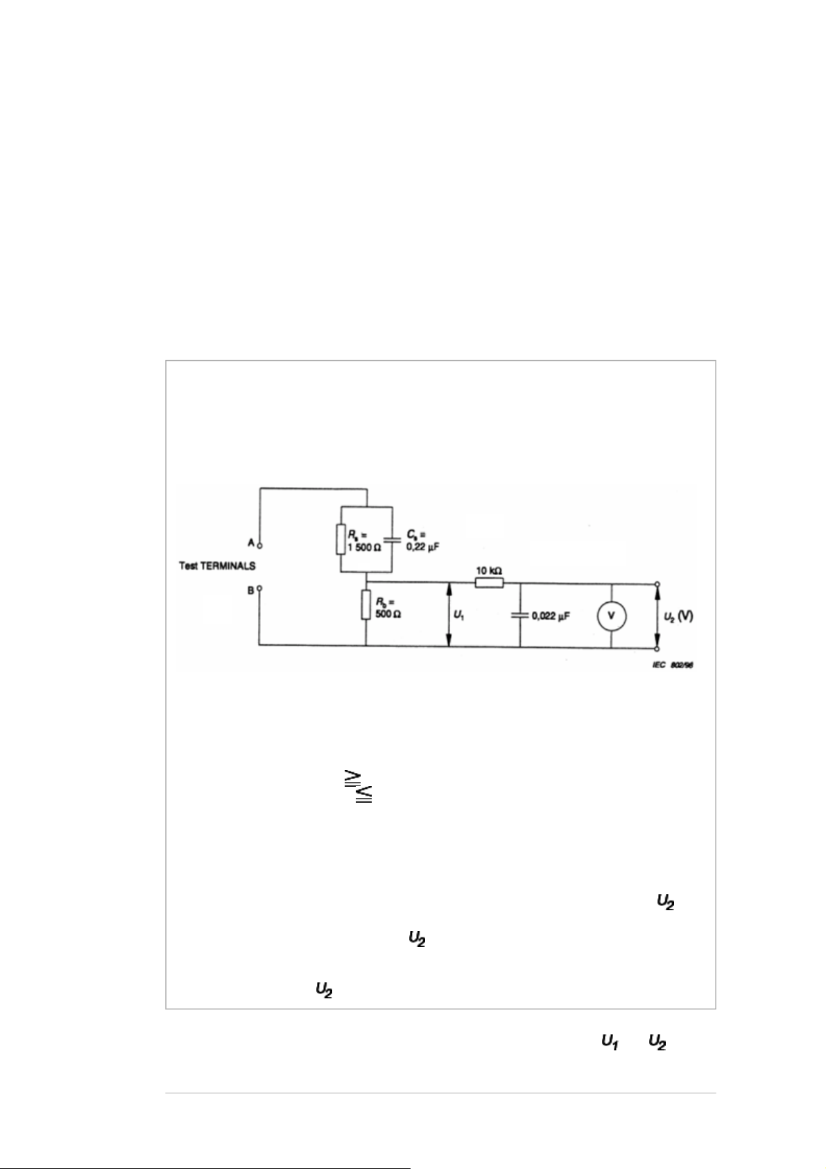
V: Voltmeter or oscilloscope
9. NEVER remodel the product in any way. Remodeling can result in improper operation,
malfunction, or electrical leakage and flame, which may be hazardous.
10. Touch current check. (After completing the work, measure touch current to prevent an
electric shock.)
Plug the AC cord directly into the AC outlet. Do NOT use an isolation transformer for
this check.
Connect a measuring network for touch currents between each exposed metallic part
on the set and a good earth ground such as a water pipe.
Annex D
(normative)
Measuring network for TOUCH CURRENTS
Resistance values in orms (Ω).
(r.m.s. or peak reading)
Input resistance : 1 MΩ
Input capacitance : 200 pF
Frequency range : 15 Hz to 1 MHz and d.c. respectively
Note: Appropriate measures should be taken to obtain the correct value in case of
non sinusoidal waveforms.
The measuring instrument is calibrated by comparing the frequency factor of with
the solid line in figure F.2 of IEC 60990 at various frequencies. A calibration curve is
constructed showing the deviation of from the ideal curve as a function of
frequency.
TOUCH CURRENT = / 500 (peak value).
The potential at any point (TOUCH CURRENT) expressed as voltage and does
not exceed the following value:
Page 7

The part or contact of a TERMINAL is not HAZARDOUS LIVE if:
with IEC 60990, with the measuring network described in
- for d.c. :
= 1.0 V
a) The open-circuit voltage should not exceed 35 V (peak) a.c. or 60 V d.c. or, if a)
is not met.
b) The measurement of the TOUCH CURRENT shall be carried out in accordance
Annex D of this
standard.
The TOUCH CURRENT expressed as voltages and , does not exceed the
following values:
- for a.c. : = 35 V (peak) and = 0.35 V (peak);
Note: The limit values of = 0.35 V (peak) for a.c. and = 1.0 V for d.c.
correspond to the values 0.7 mA (peak) a.c. and 2.0 mA d.c.
TOSHIBA WEB-ZEUS
>> terms and conditions >> privacy policy
Copyright © 1995-2011 TOSHIBA Corporation, All Rights Reserved.
Page 8

Print this page
SAFETY INSTRUCTION
Product Safety Notice
Many electrical and mechanical parts in this chassis have special safety-related characteristics.
These characteristics are often passed unnoticed by a visual inspection and the protection
afforded by them cannot necessarily be obtained by using replacement components rated for
higher voltage, wattage, etc. Replacement parts which have these special safety characteristics
are identified in this manual and its supplements; electrical components having such features are
identified by the international hazard symbols on the schematic diagram and the parts list.
Before replacing any of these components, read the parts list in this manual carefully. The use of
substitute replacement parts which do not have the same safety characteristics as specified in
the parts list may create electrical shock, fire, or other hazards.
TOSHIBA WEB-ZEUS
>> terms and conditions >> privacy policy
Copyright © 1995-2011 TOSHIBA Corporation, All Rights Reserved.
Page 9
Print this page
SAFETY INSTRUCTION
Handling the LCD Module
Safety Precaution
In the event that the screen is damaged or the liquid crystal (fluid) leaks, do not breathe in or
drink this fluid.
Also, never touch this fluid. Such actions could cause toxicity or skin irritation. If this fluid should
enter the mouth, rinse the mouth thoroughly with water. If the fluid should contact the skin or
clothing, wipe off with alcohol, etc., and rinse thoroughly with water. If the fluid should enter the
eyes, immediately rinse the eyes thoroughly with running water.
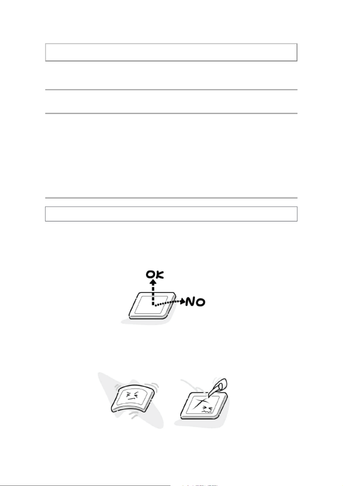
Precautions for Handling the LCD Module
CAUTION: The metal edges of the LCD module are sharp, handle it with care.
The LCD module can easily be damaged during disassembly or reassembly; therefore, always
observe the following precautions when handling the module.
1. When attaching the LCD module to the LCD cover, position it appropriately and fasten at
the position where the display can be viewed most conveniently.
2. Carefully align the holes at all four corners of the LCD module with the corresponding holes
in the LCD cover and fasten with screws. Do not strongly push on the module because any
impact can adversely affect the performance. Also use caution when handling the polarized
screen because it can easily be damaged.
3. If the panel surface becomes soiled, wipe with cotton or a soft cloth. If this does not remove
Page 10
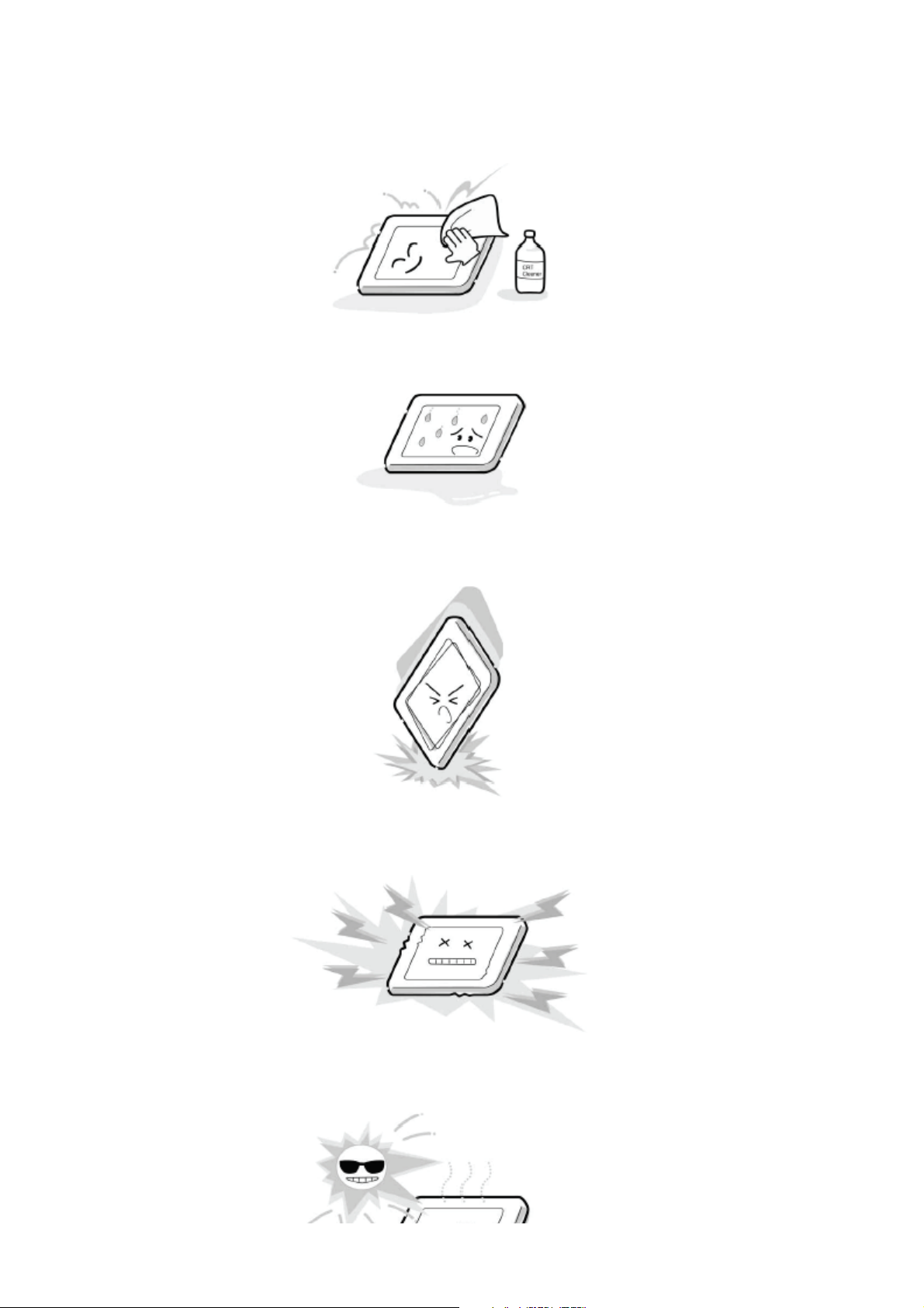
the soiling, breathe on the surface and then wipe again.
If the panel surface is extremely solied, use a CRT cleaner as a cleaner. Wipe off the panel
surface by drop the cleaner on the cloth. Do not drop the cleaner on the panel. Pay
attention not to scratch the panel surface.
4. Leaving water or other fluids on the panel screen for an extended period of time can result
in discoloration or stripes. Immediately remove any type of fluid from the screen.
5. Glass is used in the panel, so do not drop or strike with hard objects. Such actions can
damage the panel.
6. CMOS-LSI circuitry is used in the LCD module, so avoid damage due to static electricity.
When handling the module, use a wrist ground or anchor ground.
7. Do not expose the LCD module to direct sunlight or strong ultraviolet rays for an extended
period of time.
Page 11
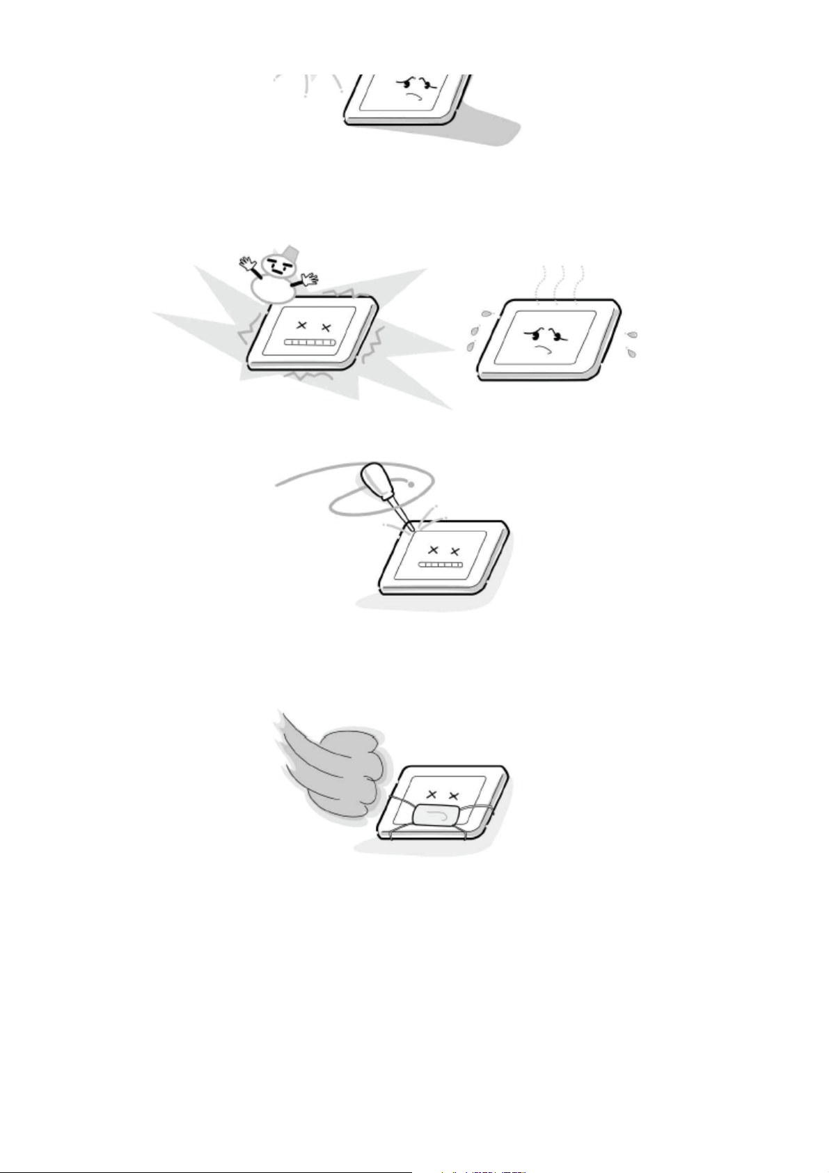
8. Do not store the LCD module below the temperature conditions described in the
specifications. Failure to do so could result in freezing of the liquid crystal due to cold air or
loss of resilience or other damage.
9. Do not disassemble the LCD module. Such actions could result in improper operation.
10. When transporting the LCD module, do not use packing containing epoxy resin (amine) or
silicon resin (alcohol or oxim). The gas generated by these materials can cause loss of
polarity.
TOSHIBA WEB-ZEUS
>> terms and conditions >> privacy policy
Copyright © 1995-2011 TOSHIBA Corporation, All Rights Reserved.
Page 12

Page 13
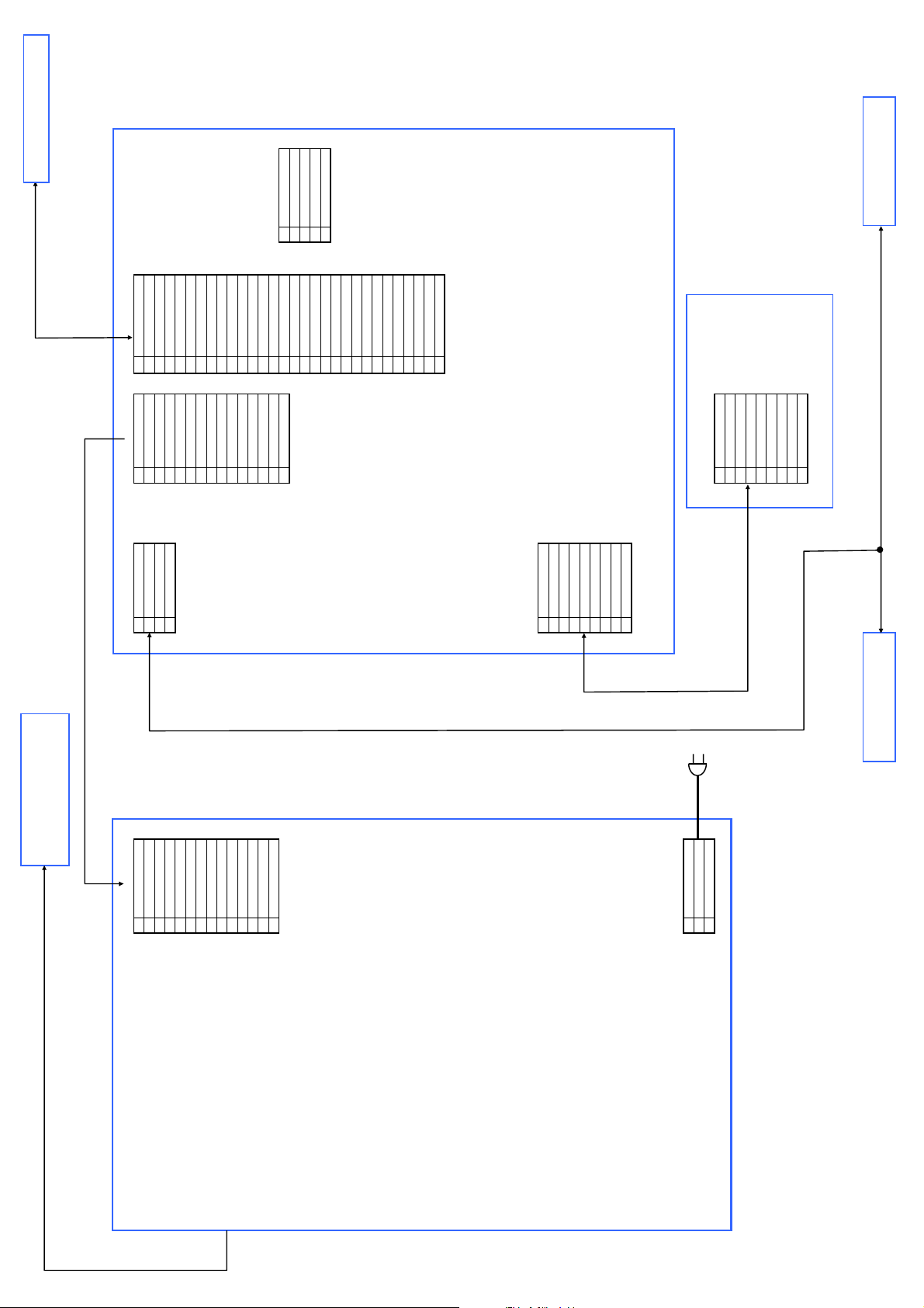
CN803 CN300 CN950 CN650
1 GND 1 L+SPK 1 GND (AUDIO) 1 NC
2 13V 2 L-SPK 2 13V (AUDIO) 2 NC
3 13V 3 R+SPK 3 13V (SIGNAL) 3 NC
4 GND 4 R-SPK 4 13V(TCON) 4 GND
5 5V 5 GND 5 TE0N
6 5V 6 5V 6 TE0P
7 GND 7 5V 7 GND
8 POWER_TV 8 GND 8 TE1N
9 AC_DET 9 POWER_TV 9 TE1P
10 GND 10 AC_DET 10 GND
11 BL_ON 11 GND 11 TE2N
12 EX_DIM 12 BL_ON 12 TE2P
13 NC 13 EXTDIM 13 GND
14 STATUS 14 INDIM 14 TECLKN CN102
15 STATUS 15 TECLKP 1 GND
16 GND 2 N/C
17 TE3N 3 +5V
18 TE3P 4 Mstar RX
19 GND 5 Mstar TX
20 NC DEBUG (OPEN)
21 SELECT
22 NC
23 GND
24 GND
25 GND
26 VLCD
27 VLCD
28 VLCD
29 VLCD
30 VLCD
CN740
1 OP IN
2 +3.3V_2
3 GND
4 +3.3V_1
5 RMT IN
6 +3.3V_1
7 POWER ON LED
8 STAND BY LED
9 GND
CN801S
1 NUTRAL
2 LIVE
3 GND PJ740
1 OP IN
2 +3.3V_2
3 GND
4 +3.3V_1
5 RMT IN
6 +3.3V_1
7 POWER ON LED
8 STAND BY LED
9 GND
PE0944-1
LED/RMT
PANEL
Speaker
PE0942
Main
POWER(LIPS)
SAMSUNG
PSIV161CO1T
PANEL T-CON
LAMP
Speaker
AC INLET
Page 14

TROUBLESHOOTING GUIDE
UNDER CONSTRUCTION
Note: Please check back in the future.
Print this page
TOSHIBA WEB-ZEUS
>> terms and conditions >> privacy policy
Copyright © 1995-2011 TOSHIBA Corporation, All Rights Reserved.
Page 15

ADJUSTMENT
Service Mode
Entering to Service Mode
Print this page
1. Press button once on remote control.
↓
↓
Service Mode display
2. Press button again and hold button down.
3. While holding the button, press MENU
button on TV set.
Page 16

TOSHIBA WEB-ZEUS
>> terms and conditions >> privacy policy
Copyright © 1995-2011 TOSHIBA Corporation, All Rights Reserved.
Page 17

ADJUSTMENT
Service Mode
Displaying the Adjustment Menu
Press MENU button on TV.
Service Mode
Print this page
Press ↑ ↓ Press
Adjustment Mode
TOSHIBA WEB-ZEUS
>> terms and conditions >> privacy policy
Copyright © 1995-2011 TOSHIBA Corporation, All Rights Reserved.
Page 18

Print this page
ADJUSTMENT
Service Mode
Key Function in the Service Mode
The following key entry during display of adjustment menu provides special functions.
CAUTION: Never try to perform initialization unless you have replaced the Main PC
Board.
Test signal selection
Selection of the adjustment items
Change of the data value
button (on remote control)
P (on remote control)
Volume +/− (on remote control)
Adjustment menu mode ON/OFF MENU button (on TV)
Initialization of the memory
"i+" + P button on TV
"RCUT" selection 1 button
"GCUT" selection 2 button
"BCUT" selection 3 button
"CNTX1" selection 4 button
"COLC2" selection 5 button
"UVTT2" selection 6 button
Automatic A/D Adjustment
(PC, Component, Composite (PAL, NTSC))
7 button
Self diagnostic display ON/OFF 9 button
TOSHIBA WEB-ZEUS
>> terms and conditions >> privacy policy
Copyright © 1995-2011 TOSHIBA Corporation, All Rights Reserved.
Page 19

Print this page
ADJUSTMENT
Service Mode
Selecting the Adjusting Item
Every pressing of P button in the service mode changes the adjustment items in the order of
table below. ( button for reverse order)
SETTING & ADJUSTING DATA
[ SERVICE MODE ]
ADJUSTING ITEMS AND DATA IN THE SERVICE MODE:
Item Name of adjustment
CNTC CNTC
CNTN CNTN
BRTX BRTX
BRTN BRTN
COLX COLX
COLN COLN
SHPX SHPX
SHPN SHPN
RCUT RCUT
GCUT GCUT
BCUT BCUT
RDRV RDRV
GDRV GDRV
BDRV BDRV
OSRC RCUT OFF SET COOL
OSGC GCUT OFF SET COOL
OSBC BCUT OFF SET COOL
OSRD RDRV OFF SET COOL
OSGD GDRV OFF SET COOL
OSBD BDRV OFF SET COOL
OSRC RCUT OFF SET NATURAL
Page 20

OSGC GCUT OFF SET NATURAL
OSBC BCUT OFF SET NATURAL
OSRD RDRV OFF SET NATURAL
OSGD GDRV OFF SET NATURAL
OSBD BDRV OFF SET NATURAL
OSRC RCUT OFF SET WARM
OSGC GCUT OFF SET WARM
OSBC BCUT OFF SET WARM
OSRD RDRV OFF SET WARM
OSGD GDRV OFF SET WARM
OSBD BDRV OFF SET WARM
TVOP TV OPTION 0 (FUNCTION 1)
OPT1 TV OPTION 1 (FUNCTION 2)
OPT2 TV OPTION 2 (HOTEL OPT1)
OPT3 TV OPTION 3 (FUNCTION 3)
OPT4 TV OPTION 4
OPT5 TV OPTION 5
OPT6 TV OPTION 6 (HOTEL OPT2)
OPT7 TV OPTION 7 (HOTEL OPT3)
OPT8 TV OPTION 8 (HOTEL OPT4)
VOLX Max limiter of Volume Control (for HOTEL mode)
Model Model ID
HTLID Hotel ID (No use for this model)
Factory preset data will be loaded after setting Model ID data.
(Refer to Initialization of TV Micro Data and setting data of signal board.)
TOSHIBA WEB-ZEUS
>> terms and conditions >> privacy policy
Copyright © 1995-2011 TOSHIBA Corporation, All Rights Reserved.
Page 21

Print this page
ADJUSTMENT
Service Mode
Adjusting the Data
Pressing of VOLUME +/− button will change the value of data in the range from 00H to FFH.
The variable range depends on the adjusting item.
TOSHIBA WEB-ZEUS
>> terms and conditions >> privacy policy
Copyright © 1995-2011 TOSHIBA Corporation, All Rights Reserved.
Page 22

ADJUSTMENT
Service Mode
Convert from Bit (Binary) to Hex
The table for converting from bit (D7-D0) to hex (0x**).
BIT (Binary)
High nibble D7 D6 D5 D4
Low nibble D3 D2 D1 D0
HEX 0 0 0 0 0
1 0 0 0 1
2 0 0 1 0
Print this page
3 0 0 1 1
4 0 1 0 0
5 0 1 0 1
6 0 1 1 0
7 0 1 1 1
8 1 0 0 0
9 1 0 0 1
A 1 0 1 0
B 1 0 1 1
C 1 1 0 0
D 1 1 0 1
E 1 1 1 0
F 1 1 1 1
E.g. If Bit D7-0 = 0101 1010, Hex data is 0x5A.
Page 23

TOSHIBA WEB-ZEUS
>> terms and conditions
>> privacy policy
Copyright © 1995-2011 TOSHIBA Corporation, All Rights Reserved.
Page 24

ADJUSTMENT
Service Mode
Exit from Service Mode
Pressing POWER button to turn off the TV once.
Print this page
TOSHIBA WEB-ZEUS
>> terms and conditions >> privacy policy
Copyright © 1995-2011 TOSHIBA Corporation, All Rights Reserved.
Page 25

Print this page
ADJUSTMENT
Service Mode
Initialization of TV Memory Data
After replacing the Main PC Board, following initialization is required.
1)
Enter Service Mode.
Select menu of Model ID by pressing P or P during display of adjustment menu in the
2)
service mode.
Confirm if the Model ID data is "0x01". If not, change ID data by pressing + or −.
3)
Press "i+" button on the Remote and hold it down. Then press the P button on the TV
4)
while holding "i+" button.
Initialization process starts, and a message window is shown as the status is "WRITING".
5) After the status changed to "OK", TV turns off and on automatically.
Then the memory initialization is completed.
Enter Service Mode and select Version Check Mode. Confirm if MODEL ID corresponding to
the model name is set correctly. If not, repeat from (2).
Note:
If wrong MODEL ID is set, abnormal display might appear.
6) Check the picture carefully. If necessary, adjust any adjustment item above.
Perform "Auto tune" on the owner's manual.
MODEL ID TABLE
Model Name Model ID (HEX) Panel Vendor
32PB1E/PB1E1/PB1V1 0x02 AUO
TOSHIBA WEB-ZEUS
>> terms and conditions >> privacy policy
Copyright © 1995-2011 TOSHIBA Corporation, All Rights Reserved.
Page 26

ADJUSTMENT
Service Mode
Initializing Data setting flowchart after replacing the Main Unit
Print this page
TOSHIBA WEB-ZEUS
>> terms and conditions >> privacy policy
Copyright © 1995-2011 TOSHIBA Corporation, All Rights Reserved.
Page 27

Page 28

Print this page
ADJUSTMENT
Service Mode
Test Signal Selection
Every pressing of button on the remote control changes the built-in test patterns on screen
as described below in Service Mode.
Picture Signal
Red raster
Green raster
Blue raster
All Black
All White
Page 29

TOSHIBA WEB-ZEUS
>> terms and conditions >> privacy policy
Copyright © 1995-2011 TOSHIBA Corporation, All Rights Reserved.
Page 30

Print this page
V1
VIDEO 1
ADJUSTMENT
Service Mode
Self Diagnostic Function
1. Press "9" button on Remote Control during display of adjustment menu in the Service
Mode. The diagnosis will begin to check if interface among IC's is executed properly.
2. During diagnosis, the following displays are shown.
(1) Firmware :
Target name and version information.
(2) Time : Total time the TV has been turned on. (Unit : Hours) (Decimal)
The time of Stand-by is not counted.
Min : 000000 max 999999 (unit hour)
(3) Bus line : "OK" is normal.
SCL-GND (Red indication) : SCL-GND short circuit
SDA-GND (Red indication) : SDA-GND short circuit
SCL-SDA (Red indication) : SCL-SDA short circuit
(4) Bus cont : "OK" is normal.
"NG" is abnormal (Red indication).
(5) Block
UV : TV reception mode
- V8 :
PC : PC input
-8 input mode
Model name : Panel vendor SA : SAMSUNG AU : AUO SH : SHARP
Block:
Page 31

UV TV
V1
(Composite)
V2
(Component)
V3 --
V4 --
V5 HDMI
V6 --
V7 --
V8 --
PC PC
1
2
TOSHIBA WEB-ZEUS
>> terms and conditions >> privacy policy
Copyright © 1995-2011 TOSHIBA Corporation, All Rights Reserved.
Page 32

Print this page
ADJUSTMENT
Service Mode
Version Check Mode
1. Press "9" button twice on Remote Control during display of adjustment menu in the Service
Mode.
2. During Version Check, the following displays are shown.
Item Explanation/Data Format
1 MAIN MPU Target name of the microprocessor
2 EEPROM Version information of EEPROM : Display 1 byte data.
3 OPTION Option information : Display three numbers of 1 byte data.
4 BL ver Version information of Boot Loader software.
5 AP ver Version information of Application software.
6 A/D Adjust A/D adjustment status.
–COMP : Component input
–PC : PC input
–NTSC : NTSC (60Hz) SD signal (composite input).
–PAL : PAL (50Hz) SD signal (composite input)
OK : A/D adjustment set correctly.
NG : A/D adjustment set incorrect.
7 Model name Model name and Panel vendor
Page 33

SA : SAMSUNG AU : AUO SH : SHARP LG : LGD CM : CMO
8 Memory Data Version Version information of EEPROM.
VDC**** means model number of EEPROM.
REV** means version of EEPROM.
TOSHIBA WEB-ZEUS
>> terms and conditions >> privacy policy
Copyright © 1995-2011 TOSHIBA Corporation, All Rights Reserved.
Page 34

Print this page
PC Normal
ADJUSTMENT
Service Mode
Status Check Mode
1. Press "9" button thrice on Remote Control during display of adjustment menu in the service
mode. The status of this model will begin to check.
2. During Status Check, the following displays are shown.
(1) MAIN :
Main source information.
Display RF position number (00 - 99) on the main screen, or Input Source (EXIT 1, HDMI 1,
PC)
(2) MAIN FORMAT :
Display Video format information.
(3) MAIN PLL :
Main PLL information.
(4) SCREEN SIZE :
Display the screen size as follows.
Native
Subtitle
14:9
Wide
4:3
SuperLive
Cinema
Page 35

PC Normal
PC Wide
Dot By Dot
(5) OTHER STATUS :
Other status information : Display three numbers of 2 byte data.
TOSHIBA WEB-ZEUS
>> terms and conditions >> privacy policy
Copyright © 1995-2011 TOSHIBA Corporation, All Rights Reserved.
Page 36

Print this page
ADJUSTMENT
Service Mode
Setting Hotel Mode
Enter Service Mode and select Hotel Mode menu by pressing P or P .
After selecting Hotel Mode, press + to enter details setting in Hotel Mode.
To select menu, press P or P and press OK to enter the adjustment menu of following table
data.
To move the cursor in the adjustment, press + or −.
1. By pressing P or P , following table data setting will change the value either 1 or 0 on
selected items as follows;
OPT2
OPT2 FUNCTION DESCRIPTION 1
D7 (bit7) Enable mode that TV standby will be set
in forced when turning the main power
ON
D6 (bit6) Enable mode that TV On will be set in
forced when turning the main power ON
D5 (bit5) Disable all buttons at side panel. Disable Enable
D4 (bit4) Disable all buttons at side panel except
input key (Video/TV).
D3 (bit3) User remote control operation Disable
D2 (bit2) Disable SET UP MENU except
language.
(Tuning/Convertor adjustment etc.)
Enable
(This function is ignored
when D6 is set to 1.)
Enable Disable
Disable
(This function is ignored
when D5 is set to 1.)
(Only setting of Service
mode and Super User mode
are possible.)
Disable
(Display language setting
only)
(This function is ignored
when D1 is set to 1.)
0
(Normal)
Disable
Enable
Enable
Enable
D1 (bit1) Disable SETUP MENU Disable Enable
D0 (bit0) HOTEL Mode On (Enable the setting of D1
to D7)
Off
(Normal)
Page 37

VOLX
VOLX FUNCTION DESCRIPTION
D7 (bit7) ~
D0 (bit0)
OPT6
OPT6 FUNCTION DESCRIPTION 1 0 (Normal)
D7 (bit7) Enable mode that POS or VIDEO program number
D6 (bit6) ~
D0 (bit0)
Maximum Volume Level
will be set in forced when turning the main power
ON
POS or VIDEO program number 0 ~ 127 [decimal]
0 ~ 100 [decimal] (Normal: 100)
Value above 100 is no effect.
Enable Disable
POS number: 0 ~ 99
VIDEO number: 100 ~ 106
VIDEO or COMPONENT:
VIDEO number = 101
HDMI: VIDEO number = 105
PC: VIDEO number = 106
(invalid data are 100, 102,
103, 104, 107 ~ 127)
If invalid number is set, POS
number 99 is used.
OPT7
OPT7 FUNCTION DESCRIPTION 1 0 (Normal)
D7 (bit7) Enable mode that speaker volume will be set in forced
when turning the main power ON
D6 (bit6) ~
D0 (bit0)
OPT8
OPT8 FUNCTION DESCRIPTION 1 0 (Normal)
D7 (bit7) Hotel Mode RS232C (no use
D6 (bit6) No use - -
D5 (bit5) Enable mode of preset POS
Forced speaker volume 0 ~ 100 [decimal]
- -
for this model)
Enable
or VIDEO number when TV
is turned ON from Standby
by TV Power button or
Remote Power button.
The POS or VIDEO number
is set in forced when the TV
is turned ON by plugging into
AC outlet, or turned ON from
Enable Disable
Value above 100 is no
effect.
Disable
The POS or VIDEO
number is set in
forced when the TV
main power is turned
Page 38

(This function is ignored
when OPT6 D7 is 0)
Standby by TV Power button
or Remote Power button.
ON only.
D4 (bit4) Selection of channel setting
mode when the TV is turned
ON by number button ("0" -
"9").
(This function is ignored
when OPT6 D7 is 0)
D3 (bit3)
RF tuning operation by P /
button on remote or front
panel of the TV set, number,
and previous key when HDMI
or PC input
D2 (bit2) Enable mode that picture
mode will be set in forced
when turning the main power
ON
D1 (bit1) ~
Forced picture mode 0 [dec]: Auto View (Normal)
D0 (bit0)
The preset POS or VIDEO is
set even though the TV is
turned ON from Standby by
number button.
The TV POS or
VIDEO is set to the
number when the TV
is turned ON from
Standby by the
number button.
Disable Enable
Enable
Disable
(Display language only)
1 [dec]: Dynamic
2 [dec]: Mild
3 [dec]: Movie
TOSHIBA WEB-ZEUS
>> terms and conditions >> privacy policy
Copyright © 1995-2011 TOSHIBA Corporation, All Rights Reserved.
Page 39

Print this page
ADJUSTMENT
Service Mode
LED Indications
Green and Red LED on the TV front panel indicate the TV operating status as described below.
«Power On/Standby»
Red ON (solid) and Green OFF = The TV power cord is plugged in, but TV is in Standby.
Green ON (solid) only. = The TV is powered on.
TOSHIBA WEB-ZEUS
>> terms and conditions >> privacy policy
Copyright © 1995-2011 TOSHIBA Corporation, All Rights Reserved.
Page 40

ADJUSTMENT
Service Mode
DTV Software Update
1. Extract the update files onto a USB device.
2. Unplug the TV from the AC outlet.
3. Connect the USB device to the USB slot on the side panel.
4. Plug the TV in the AC outlet and watch the LEDs on the front of the TV set.
The green LED blinks at first, indicating that the TV set is being updated. Never power off
during updating. After the upgrading is completed, green LED turns on.
5. Unplug the TV set from the AC outlet.
6. Disconnect the USB device.
7. Plug the TV set in the AC outlet.
Print this page
TOSHIBA WEB-ZEUS
>> terms and conditions >> privacy policy
Copyright © 1995-2011 TOSHIBA Corporation, All Rights Reserved.
Page 41

Print this page
VR
Variable Resistor
PARTS LIST
Precaution
WARNING: BEFORE SERVICING THIS CHASSIS, READ THE "SAFETY PRECAUTION"
AND "PRODUCT SAFETY NOTICE".
CAUTION: The international hazard symbols " " in the schematic diagram and the
parts list designate components which have special characteristics important for safety
and should be replaced only with types identical to those in the original circuit or
specified in the parts list.
The mounting position of replacements is to be identical with originals.
Before replacing any of these components, read carefully the "SAFETY PRECAUTION"
AND "PRODUCT SAFETY NOTICE".
Do not degrade the safety of the receiver through improper servicing.
Note:
The part number must be used when ordering parts, in order to assist in processing, be
sure to include the Model number and Description.
The PC board assembly with mark is no longer available after the end of the production.
Abbreviations
Capacitors CD : Ceramic Disk
Resistors CF : Carbon film
OMF : Oxide Metal Film
PF : Plastic Film
CC : Carbon Composition
:
EL : Electrolytic
MF : Metal Film
FR : Fusible Resistor
All CD and PF capacitors are ±5 %, 50 V and all resistor, ±5 %, 1/6 W unless otherwise noted.
Page 42

TOSHIBA WEB-ZEUS
>> terms and conditions >> privacy policy
Copyright © 1995-2011 TOSHIBA Corporation, All Rights Reserved.
Page 43

Currently there are no updates available.
Please check back at a later time for any future updates.
 Loading...