

Toshiba 32P1300DG Service Manual

SERVICE MANUAL
LCD Color Television
32P1300D(G)

CONTENTS
1. IMPORTANT NOTICE
2. GREEN PRODUCT PROCUREMENT
3. LEAD-FREE SOLDER
4. SAFETY INSTRUCTION
5. SERVICE MODE
6. INTERCONNECT
7. EXPLODED VIEW
8. SET ID and PANEL ID
1

IMPORTANT NOTICE
WARNING:
You are requested that you shall not modify or alter the information or data provided
herein without prior written consent by Toshiba. Toshiba shall not be liable to
anybody for any damages, losses, expenses or costs, if any, incurred in connection
with or as a result of such modification or alteration.
THE INFORMATION OR DATA HEREIN SHALL BE PROVIDED "AS IS" WITHOUT ANY
WARRANTY OF ANY KIND, EITHER EXPRESS OR IMPLIED WARRANTY OF
MERCHANTABILITY AND FITNESS FOR A PARTICULAR PURPOSE.
Toshiba shall not be liable for any damages, losses, expenses or costs, if any,
incurred in connection with or as a result of use of any information or data provided
herein.

GREEN PRODUCT PROCUREMENT
The EC is actively promoting the WEEE & RoHS Directives that define standards for
recycling and reuse of Waste Electrical and Electronic Equipment and for the Restriction of
the use of certain Hazardous Substances. From July 1, 2006, the RoHS Directive will
prohibit any marketing of new products containing the restricted substances.
Increasing attention is given to issues related to the global environmental. Toshiba
Corporation recognizes environmental protection as a key management tasks, and is doing
its utmost to enhance and improve the quality and scope of its environmental activities. In
line with this, Toshiba proactively promotes Green Procurement, and seeks to purchase
and use products, parts and materials that have low environmental impacts.
Green procurement of parts is not only confined to manufacture. The same green parts
used in manufacture must also be used as replacement parts.
LEAD-FREE SOLDER
This product is manufactured using lead-free solder as a part of a movement within the
consumer products industry at large to be environmentally responsible. Lead-free solder
must be used in the servicing and repair of this product.
WARNING: This product is manufactured using lead free solder.
DO NOT USE LEAD BASED SOLDER TO REPAIR THIS PRODUCT!
The melting temperature of lead-free solder is higher than that of leaded solder by 30ºC to
40ºC (54ºF to 72ºF). Use of a soldering iron designed for lead-based solders to repair
product made with lead-free solder may result in damage to the component and or PCB
being soldered. Great care should be made to ensure high-quality soldering when servicing
this product especially when soldering large components, through-hole pins, and on PCBs
as the level of heat required to melt lead-free solder is high.

(1/4)
SAFETY INSTRUCTION
WARNING: BEFORE SERVICING THIS CHASSIS, READ THE "SAFETY PRECAUTION"
AND "PRODUCT SAFETY NOTICE" INSTRUCTIONS BELOW.
Safety Precaution
WARNING: SERVICING SHOULD NOT BE ATTEMPTED BY ANYONE UNFAMILIAR WITH
THE NECESSARY PRECAUTIONS ON THIS RECEIVER. THE FOLLOWING ARE THE
NECESSARY PRECAUTIONS TO BE OBSERVED BEFORE SERVICING THIS CHASSIS.
1. An isolation transformer should be connected in the power line between the receiver
and the AC line before any service is performed on the receiver.
2. Always disconnect the power plug before any disassembling of the product. It may
result in electrical shock.
3. When replacing a chassis in the cabinet, always be certain that all the protective
devices are put back in place, such as nonmetallic control knobs, insulating covers,
shields, isolation resistor-capacitor network, etc.
4. Always keep tools, components of the product, etc away from the children, These items
may cause injury to children.
5. Depending on the model, use an isolation transformer or wear suitable gloves when
servicing with the power on, and disconnect the power plug to avoid electrical shock
when replacing parts. In some cases, alternating current is also impressed in the
chassis, so electrical shock is possible if the chassis is contacted with the power on.
6. Always use the replacement parts specified for the particular model when making
repairs. The parts used in products require special safety characteristics such as
inflammability, voltage resistance, etc. therefore, use only replacement parts that have
these same characteristics. Use only the specified parts when the
mark is indicated
in the circuit diagram or parts list.
7. Parts mounting and routing dressing of wirings should be the same as that used
originally. For safety purposes, insulating materials such as isolation tube or tape are
sometimes used and printed circuit boards are sometimes mounted floating. Also make
sure that wirings is routed and clamped to avoid parts that generate heat and which use
high voltage. Always follow the manufactured wiring routes / dressings.
(2/4)
8. Always ensure that all internal wirings are in accordance before re-assembling the
external casing after a repairing completed. Do not allow internal wiring to be pinched
by cabinets, panels, etc. Any error in reassembly or wiring can result in electrical
leakage, flame, etc., and may be hazardous.
9. NEVER remodel the product in any way. Remodeling can result in improper operation,
malfunction, or electrical leakage and flame, which may be hazardous.
10. Touch current check. (After completing the work, measure touch current to prevent an
electric shock.)
Plug the AC cord directly into the AC outlet. Do NOT use an isolation transformer for
this check.
Connect a measuring network for touch currents between each exposed metallic part
on the set and a good earth ground such as a water pipe.
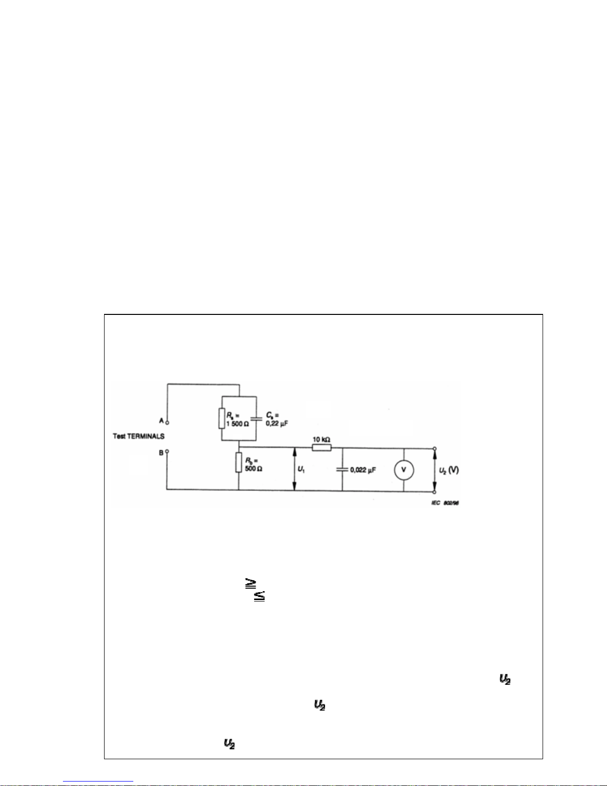
Annex D
(normative)
Measuring network for TOUCH CURRENTS
Resistance values in orms (Ω).
V: Voltmeter or oscilloscope
(r.m.s. or peak reading)
Input resistance :
1 MΩ
Input capacitance : 200 pF
Frequency range : 15 Hz to 1 MHz and d.c. respectively
Note: Appropriate measures should be taken to obtain the correct value in case of non
sinusoidal waveforms.
The measuring instrument is calibrated by comparing the frequency factor of with
the solid line in figure F.2 of IEC 60990 at various frequencies. A calibration curve is
constructed showing the deviation of
from the ideal curve as a function of
frequency.
TOUCH CURRENT =
/ 500 (peak value).
(3/4)
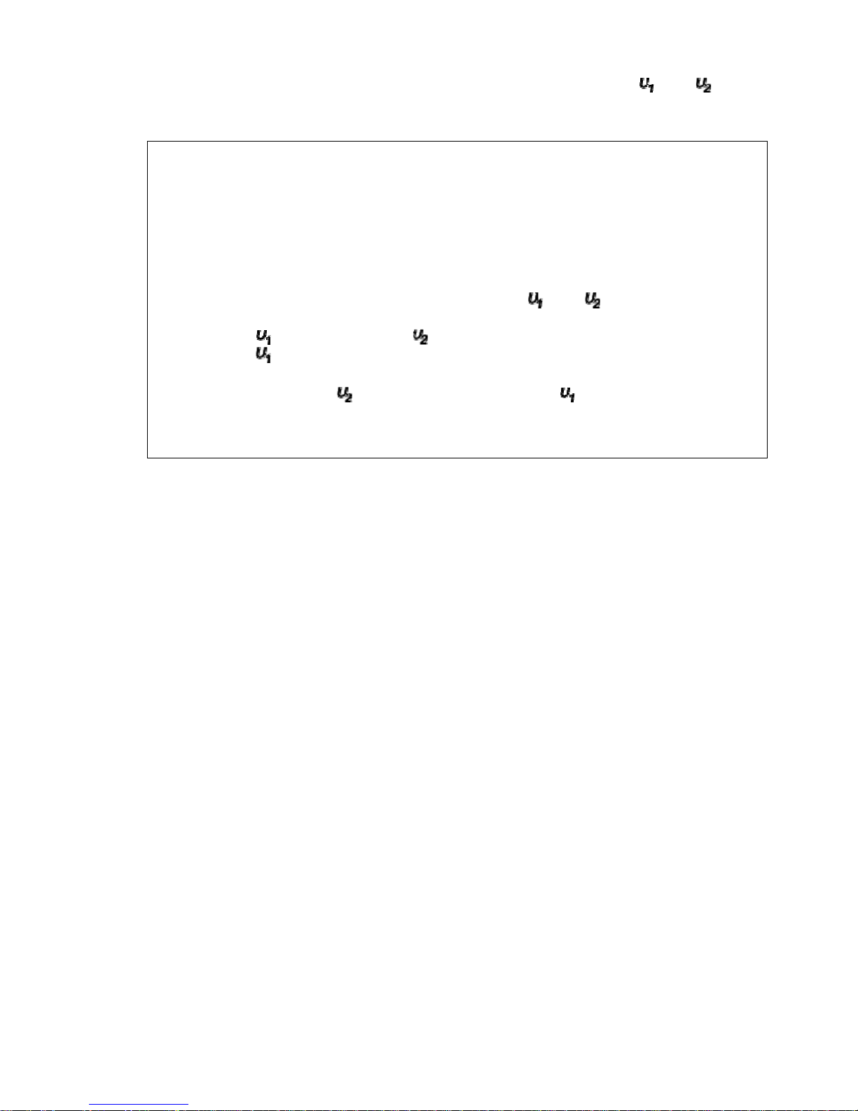
The potential at any point (TOUCH CURRENT) expressed as voltage and does
not exceed the following value:
The part or contact of a TERMINAL is not HAZARDOUS LIVE if:
a) The open-circuit voltage should not exceed 35 V (peak) a.c. or 60 V d.c. or, if a) is
not met.
b)
The measurement of the TOUCH CURRENT shall be carried out in accordance
with IEC 60990, with the measuring network described in Annex D of this
standard.
The TOUCH CURRENT expressed as voltages and , does not exceed the
following values:
- for a.c. : = 35 V (peak) and = 0.35 V (peak);
- for d.c. : = 1.0 V
Note: The limit values of = 0.35 V (peak) for a.c. and = 1.0 V for d.c.
correspond to the values 0.7 mA (peak) a.c. and 2.0 mA d.c.

(4/4)
Product Safety Notice
Many electrical and mechanical parts in this chassis have special safety-related characteristics.
These characteristics are often passed unnoticed by a visual inspection and the protection
afforded by them cannot necessarily be obtained by using replacement components rated for
higher voltage, wattage, etc. Replacement parts which have these special safety
characteristics are identified in this manual and its supplements; electrical components having
such features are identified by the international hazard symbols on the schematic diagram and
the parts list.
Before replacing any of these components, read the parts list in this manual carefully. The use
of substitute replacement parts which do not have the same safety characteristics as specified
in the parts list may create electrical shock, fire, or other hazards.
(1/13)
SERVICE MODE
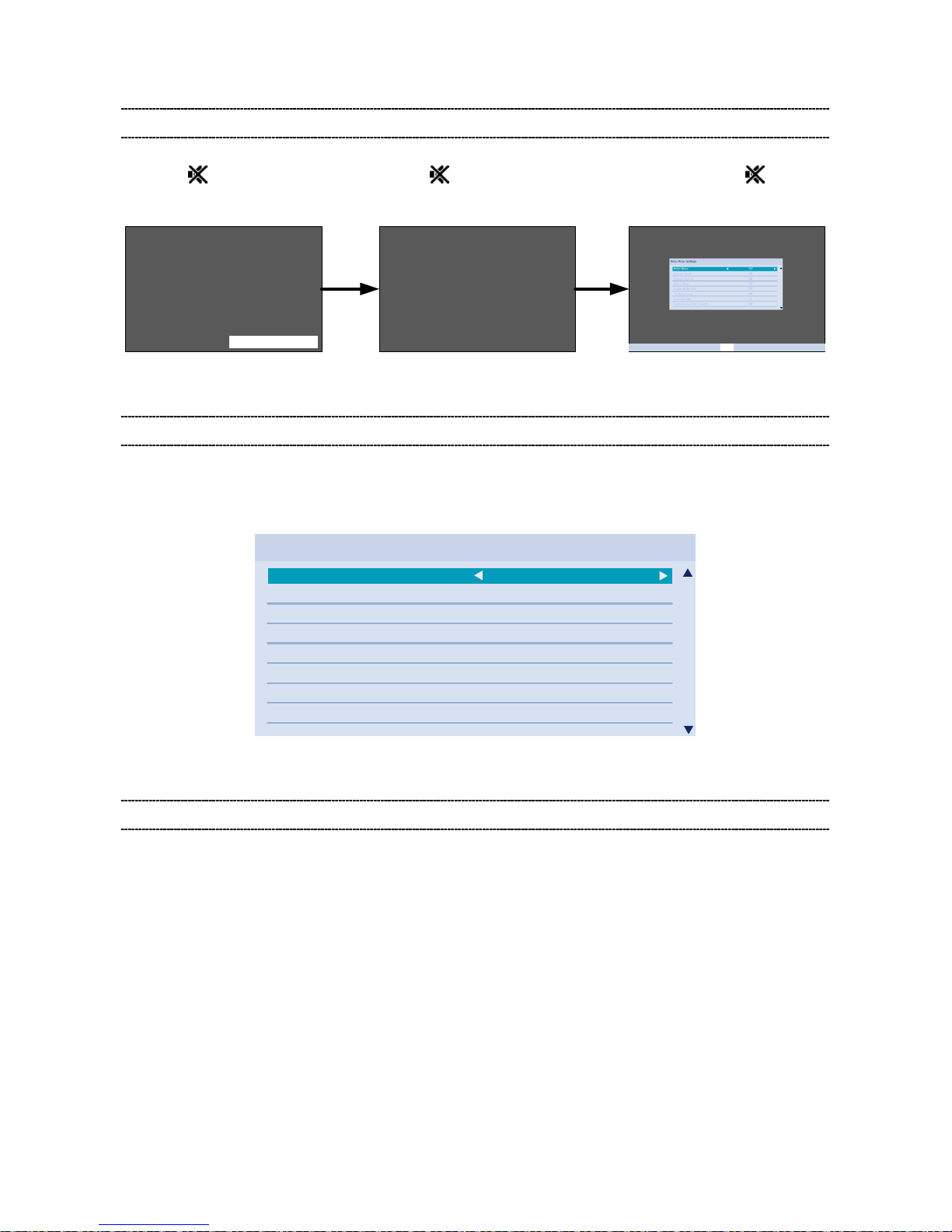
ENTERING SERVICE MODE
1) Press button once on 2) Press button again and 3) While pressing the button,
Remote Control. keep pressing. press button on TV set.
SERVICE MENU
Self Check
[9]Key [9]Key

(2/13)
ADJUSTING ITEMS IN THE SERVICE MODE
Special setting
Item Value Purpose
Vertical Line Normal, Special
if the picture have "Vertical Line problem",
user can use the "special setting" to improve this problem
V Lock
Normal, Special
if the picture have "up-down jitter problem",
user can use the "special setting" to improve this problem
White Tail
Normal, 1, 2, 3, 4
if the picture have "White Tail problem",
user can adjust the setting to improve this problem
Color Flicker Normal, Special
When the color of the screen is flashing
user can use the "special setting" to improve this problem
White Peak Normal, Special
if the picture have "bright dark flashing problem",
user can use the "special setting" to improve this problem
H Jitter
Normal, _00,
_01,_02,_03,_04,_05
if the picture have "left- right jitter problem",
user can use the "special setting" to improve this problem
Vsync
Threshold
Normal, 1,2
if the vsync of the signal is not locking ,user can use the
"special setting" to improve this probl em
Normal is current condition.
1 is current special + add one register (for Mumbai Ch2).
2 is 3 combination (Change IFD Gain+V th+ V PLL)(for Delhi
Ch2).
IF AGC Speed
196,206,216,219,222,24
8,250,251,Default,89,10
5,121,137,158,172,185
the default setting is the 196, user can use this setting to
change the if AGC speed
When user changes setup, setting value is held to each CH.
LogDebug Enable/Disable
Default: Disable for TEST purpose
Signal
det.Hsync
Normal/Special
Normal is current condition (Vsync and Hsync)
Special is new condition (Hysnc only)
Factory Reset
Execute Factory Reset (Shipment condition)
CH WIDTH
VIDEO SYS
Normal/Special
Normal is current condition
Special is new condition (VIDEO SYSTEM:PAL-G)
When user changes setup, setting value is held to each CH.
PAL-G is Tuner si2156 control setting.
Agc loop 1 dn
sample
Normal/Special
Normal is current condition (" 3 " Setting)
Special is new condition ( " 0 " Setting)
When user changes setup, setting value is held to each CH.
A A B C D
F E D

(3/13)
A : These item are similar phenomenon. So please try both items.
B : The picture have white horizontal flare or some portion lost horizontal synchronize (disarray).
In this case please try to change “White tail” 1, 2, 3, or 4.Then please choose the best one.
C : If the picture have horizontal jitter please try to change this “H Jitter” 01, 02, 03, 04, and 05.
Then please select the best one.
D : If the picture have horizontal bar noise or unlock synchronize please try to reduce this value.
E : If the picture have full screen Picture jumping up / down please try a change to “special”.
F : If the picture have horizontal stripes please try a change to “special”.

(4/13)
SELF CHECK
- “Self Check” screen is sh o wn by pressi ng “9” button on R emote Cont rol d urin g disp lay o f the Service
mode adjustment menu.
- “Self Check” screen should not be erased by t ime out .
Self Check OSD
1
TV Model
32P1300D_A_LGD
2
Model ID
0x03
3
Boot Version
00000
4
APP SW Version
00000
5
PQ Data Version
00
6
AQ Data Version
00
7
Language H
Enable
8
CEC Playback Control
Disable
9
HDCP Key
Pass [EEPROM]
10
POT
00000
11
MAIN FORMAT
1080i 60
12
MAIN TUNER FREQ
00000000
13
(5/13)
Item Explanation /Data Format
TV Model
“Model name”+”_”+”Suffix(A or B)”+”_”+”Panel vender”
e.g. 32P1300D_A_LGD
Model name :
29P1300D, 32P1300D
Suffix:
A
Panel vender :
LGD:LGD , CMI:CMI
Model ID Model ID indicating panel size and vender
Display 1 byte data.(Hex)
Boot Version Version information of boot code.
APP SW Version Version information of Application SW.
PQ Data Version Version information of Picture Quality Data.
AQ Data Version Version information of Audio Quality Data.
Language H
Manu Language option for VQ model
Enable : Enable to select Menu Language for VQ model.
Disable : Disable to select Menu Language for VQ model.
CEC Playback Control
Pass through of playback control keys option for HDMI-CEC
Enable : Playback control keys are handled as pass through.
Disable : Playback control keys are not handled as pass through.
HDCP key
HDCP key in the memory
Pass(FLASH) : HDCP key is detected in Flash-ROM
Pass(EEPROM) : HDCP Key is detected in Extern al E EPROM
Fail : HDCP key is not detected
POT
Power On Time
Total time the TV has been powered on. (Unit: Hours) (Decimal)
* Writing the POT data to Flas h ROM should be done only once in an hour.
(The time less than one hour can be ignored.)
* POT should be cleared to 0 by the ship-out factory command (40EE00FF).
MAIN FORMAT Video format information (e.g. 480i60, 1080i50, 1024 x 768@60Hz)
MAIN TUNER FREQ. Displays tuned frequency (Unit: kHz) (Decimal)

(6/13)
MODEL ID TABLE
Model
ID
Inch & Vendor
Model Name in
Self Check OSD
0x00
Not used
0x01
29P1300_CMI
29P1300D_CMI
29P1300_A_CMI
29P1300D_A_CMI
0x02
Reserved
0x03
32P1300_LGD
32P1300_A_LGD
0x04
32P1300_LGD
32P1300D_LGD
32P1300_A_LGD
32P1300D_A_LGD
0x05
32P1300_AUO(TBD)
32P1300_A_AUO
0x06
32P1300_CMI(TBD)
32P1300_A_CMI
0x07
Reserved
0x08
24P1300_CMI
24P1300_A_CMI
0x09
Reserved
0x0A
Reserved
0x0B
Reserved
Note
P1300D (East Euro) is the following two Model.
・29P1300D_CMI
・32P1300D_LGD
SETTING HOTEL MODE
Hotel mode allows for cust om iz ing specified TV operations that are suitable for hotel use.
(7/13)
ENTERING HOTEL MODE MENU
Hotel Mode Menu should be show n by the following operation.
1) Press
button once on the 2) Press button again and 3) While pressing the button,
Remote Control. keep pressing. press “+” button on TV set.
(Hotel Mode Settings Men u)
DISPLAY OF HOTEL MODE MENU
- The Hotel Mode Menu s hould always be shown in English regar dless of the Menu Language s et t ing.
(Translation of the words in the Hotel Mode Menu will not be provided.)
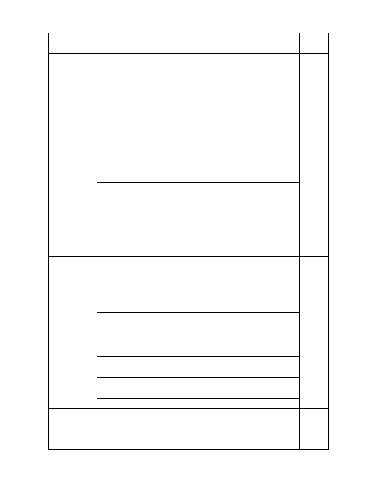
Hotel Mode Settings
Hotel Mode On
Control Panel On
Remote Control On
Setup Menu On
Enable HDMI CEC
TV Auto Power On
Auto Standby On
Position Key Pass Through Off
On
(Example of Menu Image)
OPERATING HOTEL MODE MENU
- To enable Hotel Mode, use the or arrow keys while “Hotel Mode” item is highlighte d to select “ On”.
Once Hotel Mode is on, the Hotel M ode settings will be enabled for adjusting.
- Use ▲ and ▼ buttons to ac cess t he hotel mode settings.
Use and buttons to change the settings.
See the table below for explanation of each setting.
- Press Exit when finished adjusting the settings.
(8/13)
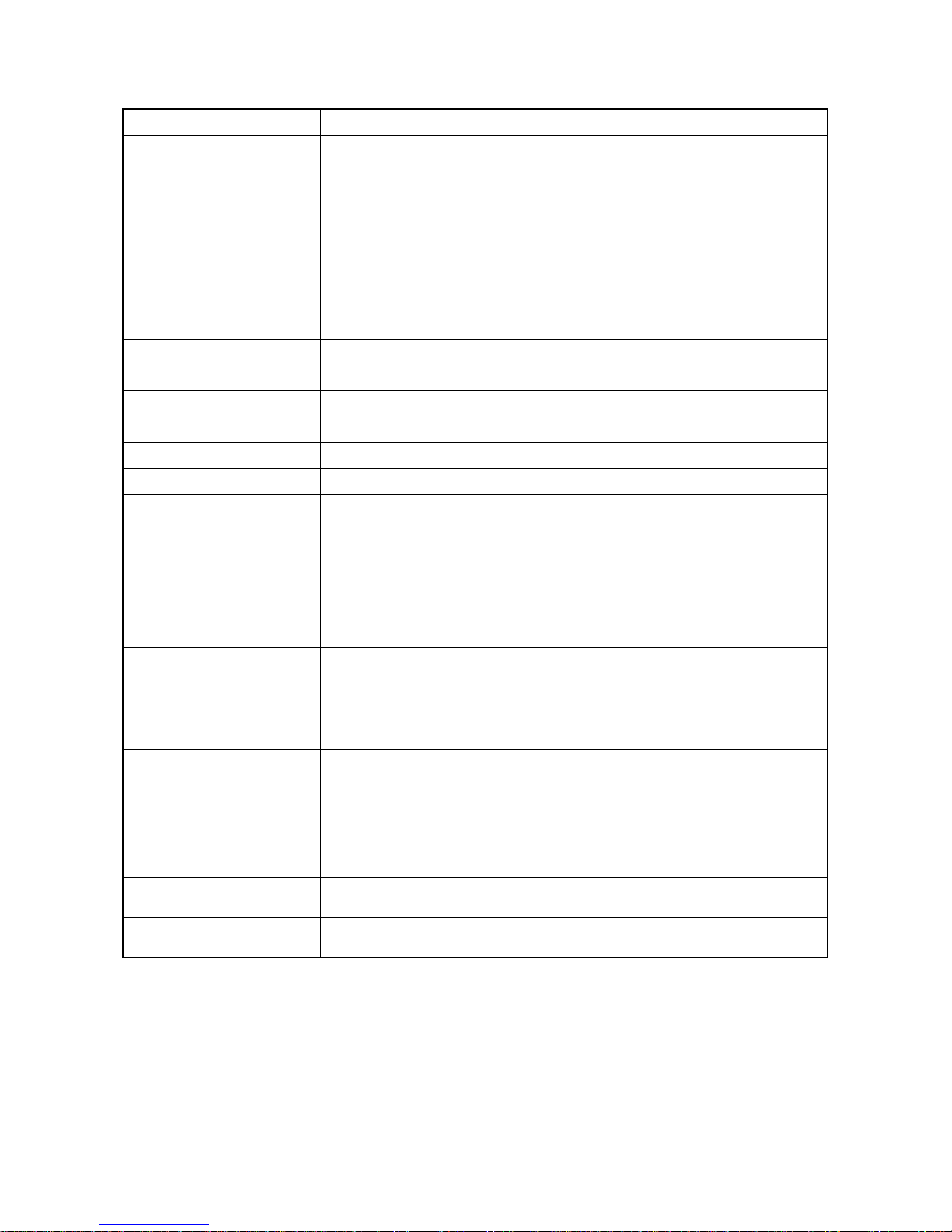
Item Options Description
Factory
settings
Hotel Mode Off Disable Hotel Mode.
All the settings of Hotel Mode are disabled.
Off
On Enable Hotel Mode
Control Panel On Allow use of all Control panel buttons On
Off Prohibit use of all control panel buttons.
But, Power Off -> On by control panel POWER button is
not prohibited.
(Power On -> Off is prohibited.)
* Entering Service mode/Hotel mode Menu/Hotel Clone is
not prohibited.
* Control panel buttons are available during Service mode.
Remote Control On Remote Enabled On
Off Remote Disabled
* The following remote codes are not disabled.
- SOUND MUTE (40BF10)
- Super User mode (40BFFE)
- S mode (40EEC3)
* Remote Enabled during Service mode/Hotel mode
Menu/Hotel Clone.
Setup Menu On Allow access to SETUP menu On
Off Prohibit access to the setup menu.
Off (Except
Language)
Prohibit access to all items in the setup menu except for
the Language setting.
Enable HDMI
CEC
On Enable to use CEC feature Off
Off “TV Auto Power” and “Auto Standby” and “Position Key
Pass Through” are grayed out. CEC feature will not be
available regardless the settings.
TV Auto Power On Control power On/Off from external device On
Off Prohibit control of power On/Off from external device
Auto Standby On Execute standby to external device On
Off Prohibit control of standby to external device
Position Key
Pass Through
On Pass through position keys to external device. Off
Off Prohibit “pass through” to external device.
Max Volume 0-100 Set maximum volume level.
It limits the volume level which can be set b y Volume
button.
If you set it to 70, Volume bar can not go to 71 or higher.
100
(9/13)
Change
POS/VIDEO
Off TV Tunes to the last channel or input viewed when
powered on
Off
On TV tunes to preset “POS/VIDEO” (channel or input) when
TV is powered on.
On (AC) TV tunes to preset “POS/VIDEO” (channel or input) only
when AC power is applied.
When TV is powered on by power button, tune to the last
channel or input.
POS/VIDEO
(only available
when “Change
POS/VIDEO” is
On)
0-99 0-99 (TV Channel Position) 0
VIDEO Number of input is depends on model.
HDMI Number of input is depends on model.
Change Volume Off TV volume level does not change when TV powers on Off
On TV volume level is forced to “Volume” level when TV is
powered on
Volume
(only available
when “Change
Volume” is On)
0-100 Volume level when TV is powered on
(Level bar is displayed)
30
Change Picture
Mode
Off Picture setting mode does not change when TV is
powered on
Off
On Picture setting mode is forced to “Picture Mode” mode
when TV is powered on
Picture Mode
(only available
when “Change
Picture Mode” is
On)
Dynamic Dynamic Standard
Standard Standard
Mild Mild
Movie Movie
TV Power Disabled TV returns to previous Standby/On State when AC power
is applied
Disabled
Force On Power TV on when AC power is applied
Force Standby Put TV in Standby when AC power is applied
Position Change
on HDMI Input
Enabled RF tuning via P▲, P▼, BACK, and number buttons is
allowed. (Normal operation)
Enabled
Disabled When viewing HDMI input, RF tuning via P▲, P▼, BACK,
and number buttons is disabled.
(10/13)
RESETTING HOTEL MODE SETTINGS
- Hotel Mode settings sho uld b e r es et by special remote code for Factory Ship out.
(Default values will be rest or ed)
- Hotel Mode settings sho uld NO T be reset by “Reset TV” on the S ET UP menu.
(To prevent users from cancelling Hotel Menu set t ings that has been specially set by the hotel)
CLONING HOTEL MODE SETTINGS
- Hotel Mode settings sho uld b e c opied to other TV by HOTEL CLONE function.
SETTING HOTEL MODE VIA CLONE MENU
The following settings can be copied between sets using the clone menu:
o Hotel Mode menu settings
o ATV Channel Setup
Programme (position)
System
Colour System
Programme Skip
Signal Class
Channel
Manual Fine Tuning
Signal Booster
Label
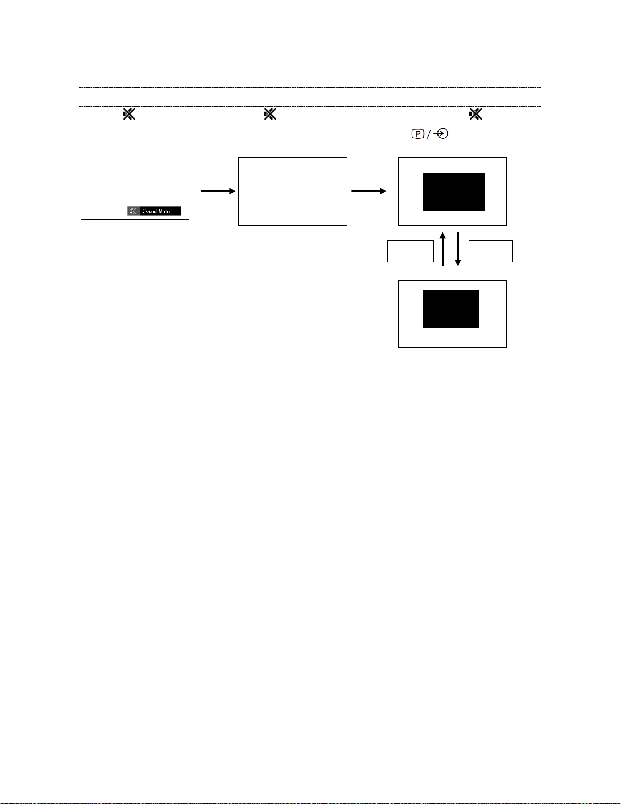
COPYING HOTEL MODE SETTINGS FROM TV TO USB DRIVE
1) Configure the hotel mode set t ings via the Hotel Mode Menu (see previous sections for instructio ns) .
2) Setup channel list via Setup M enu.
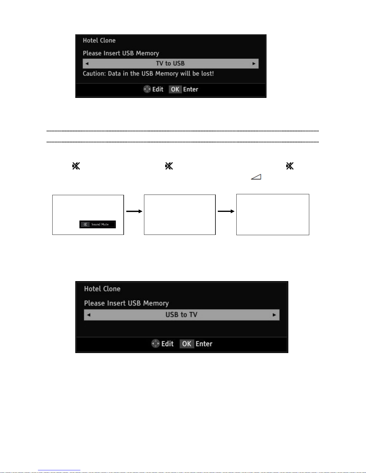
3) Access the Hotel Clone menu using steps a-c.
a) Press
button once on the b) Press button again and c) While pressing the button,
Remote Control. keep pressing. press button on TV set .
4) Select “TV to USB” using the or arrow keys.
(Hotel Clone menu display)
(Sound Mute display)
(Sound Mute display is canceled)
(11/13)
5) Insert USB Drive and pres s O K t o copy settings to the USB drive.
6) Wait for window that indicat es t he c opying process is complete before removing the USB drive.
COPYING HOTEL MODE SETTINGS FROM USB DRIVE TO TV
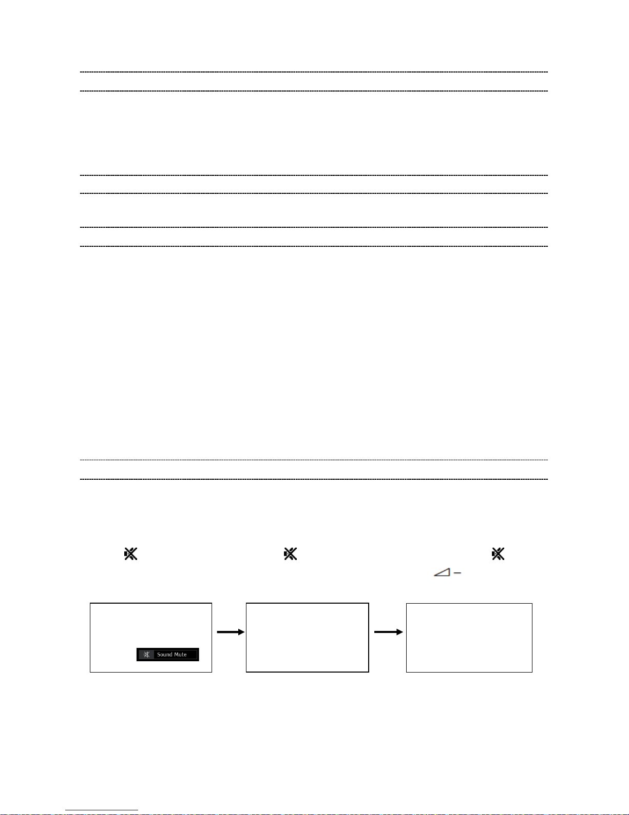
1) Access the Hotel Clone menu using steps a-c.
a) Press button once on the b) Press button again and c) While pressing the button,
Remote Control. keep pressing. press “ -” button on TV set.
2) Select “USB to TV” using the or arrow keys.
3) Insert USB Drive that settings have previously been saved to and press OK to copy settings to the
TV.
4) Wait for settings to be copied.
When the copying has finished successfully, the message “ The T V w ill reboot when this window
is closed.” will be displayed. If the copying is not successful, an error mes sage will be displayed.
5) Exit the menu and the TV will reboot.
6) Remove the USB drive.
(Hotel Clone menu display)
(Sound Mute display)
(Sound Mute display is canceled)

(12/13)
Note:
If TV status is “out of Box“ condition, when turn on the TV first, “Quick Setup“ screen will be displayed.
Before copying data to TV from USB by using Hotel Clone function, it is neces sar y to execute Auto
Tuning for the purpose of disappearing the “Quick Setup“ scr een.
 Loading...