

Page 1
Digital Media Network Company
CTV & Visual Media Equipment Div.
International Customer Servic e & Support Dept. [34F-A]
1-1,SHIBAURA 1-CHOME, MINATO-KU T OKYO 105-8001,JAPAN
PHONE:(03)3457-3536
FACSIMILE:(03)5444-9408
SERVICE INSTRUCTION
Product: LCD TV
Model: 26/32HL84, 26/32WL46B/G/C/A/E/R/T
Corrective Action: Backlight Lamp unit as a service part
Part No. Description Model applied
File No.01C2005002R
Date: Mar.11,2005
Rank: C
23587241 Back light unit 26HL84, 26WL46B/G/C/A/E/R/T
23587242 Back light unit 32HL84, 32WL46B/G/C/A/E/R/T
Product Safety Precautions:
Product Safety Precautions are described in Toshiba service manuals
020-200403 and 020-200405 for the model(s) covered in this bulletin. All
safety precautions and checks shall be complied with before returning the
equipment to the customer. Servicers who defeat safety features or fail to
perform safety checks may be liable for any resulting damages and may
expose themselves and others to possible injury.
__________________
Hideto Kitamura
Manager
International Customer
Service & Support Dept.
©2005 TOSHIBA AMERICA CONSUMER PRODUCTS, LLC
Page 2
Model: 26HL84, 26WL46B/G/C/A/E/R/T
1. Cautions for Backlight Lamp Unit Replacement
The backlight lamps used in the listed Liquid Crystal Display (LCD) modules are
consumables. Follow the included replacement procedures when replacing these
components.
Disconnect AC power before starting the replacement procedure. The high
voltage applied to the backlight lamps produces an electrical shock hazard if
caution is not used when servicing this area.
Backlight lamp units are fragile and caution should be used when handling.
Ferrite cores are attached to the backlight lamp units with double-sided adhesive
tape. Use caution when removing these ferrite cores, as excessive force may
cause damage.
Where possible, replace backlight lamp units in a clean and dust-free environment.
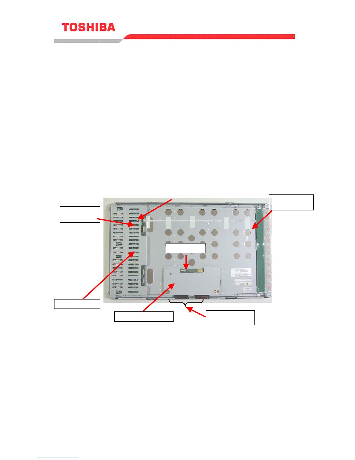
TFT-LCD Module Bottom view
Return FFC
INV board
(HOT) side
INV board
(GND) side
INV cover
C board cover
C board
Flat cables
Ferrite cores
2004 LCD Television
Service Instruction
Page 1 of 1
2
Page 3
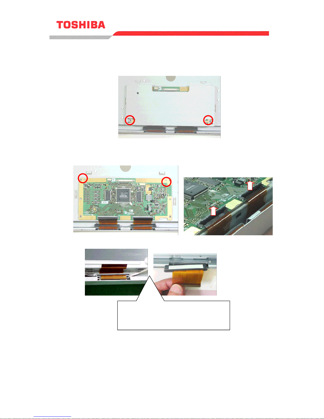
2. Removing C Board Cover and C Board
2.1. Remove the two screws securing the C board cover.
2-2. Remove the two screws securing the C board. Remove the C board and
connectors, using caution to remove the ferrite cores.
Use caution when removing the ferrite
cores, as excessive force may cause
damage.
Service Instruction
2004 LCD Television
Page 2 of 12
Page 4
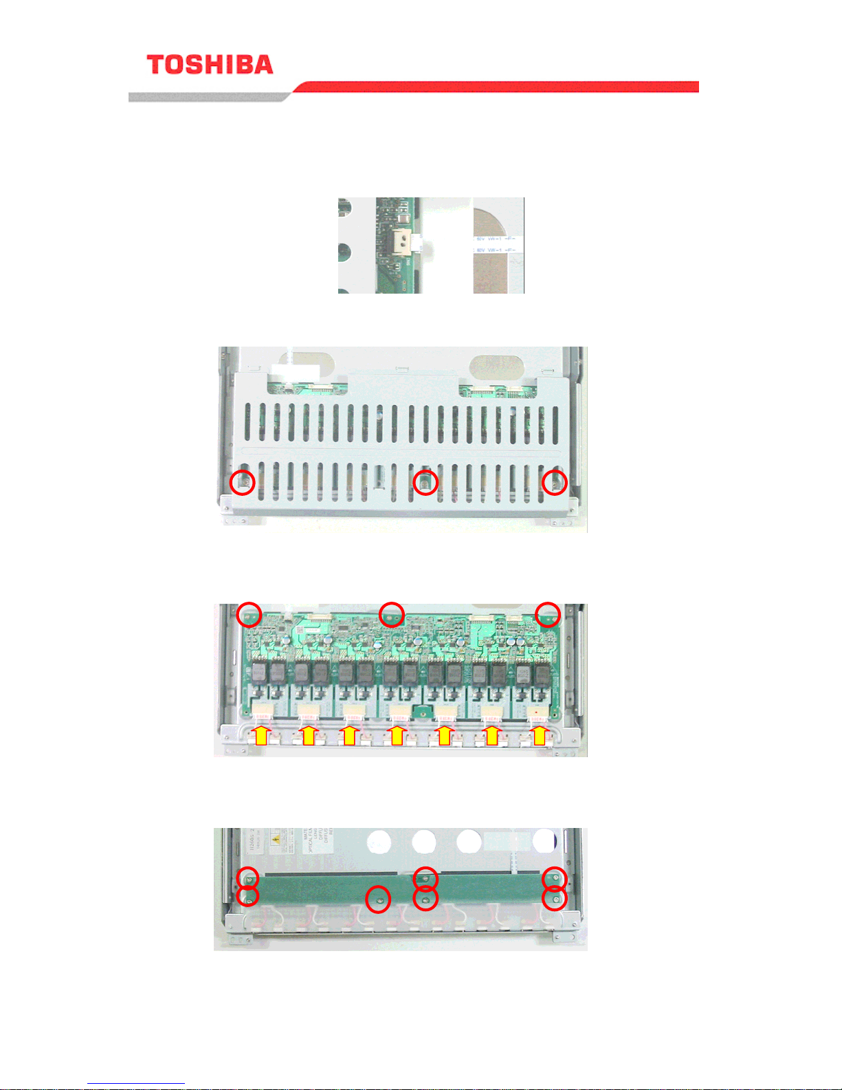
3. Removing INV Cover and INV Board (HOT Side / GND Side)
3-1. Remove the return FFC connected to the INV board.
3-2. Remove the three screws securing the INV cover.
3-3. Disconnect the seven lamp unit connectors and remove the three screws
securing the INV board (HOT side).
3-4. Disconnect the seven lamp unit connectors and remove the seven screws
securing the INV board (GND side).
Service Instruction
2004 LCD Television
Page 3 of 12
Page 5

4. Removing Panel Unit and Lamp Holder
4-1. Remove the 20 screws securing the panel unit.
4-2. Remove the six screws securing the lamp holder.
Service Instruction
2004 LCD Television
Page 4 of 12
Page 6

5. Replacing Lamp Units
5-1. Remove the old lamp units from the lamp clip, and replace them with new ones.
Be very careful not to break the lamp units when detaching/reattaching them. Keep
dust off the units.
Note: The seven lamp direct illumination system uses 14 CCFTs
(Cold Cathode Fluorescent Tubes) to provide backlighting for
the LCD display.
One lamp unit consists
of two lamps.
Small connector
Connected to INV board
(GND side)
Large connector
Connected to INV board
(HOT side)
Service Instruction
2004 LCD Television
Page 5 of 12
Page 7

6. Assembly
6-1. Follow the lamp unit removal instructions in reverse order to re-assemble
the backlight lamp assembly. (Section2-5).
Assembly Cautions
Handle fragile lamp units with extreme caution.
Replace lamp units in a dust-free environment.
Do not bend or pinch flat cables when installing the panel unit.
Ferrite core may be damaged even by a slight shock. Attach ferrite cores
very carefully.
Connect the connectors securely to the INV board.
Connect small connectors
to the INV board (HOT
side).
Connect small connectors
to the INV board (GND
side).
INV board (HOT side)
INV board (GND side)
Panel unit
Flat cables
Service Instruction
2004 LCD Television
Page 6 of 12
Page 8

Model: 32HL84, 32WL46B/G/C/A/E/R/T
1. Cautions for Backlight Lamp Unit Replacement
The backlight lamps used in the listed Liquid Crystal Display (LCD) modules are
consumables. Follow the included replacement procedures when replacing these
components.
Disconnect AC power before starting the replacement procedure. The high
voltage applied to the backlight lamps produces an electrical shock hazard if
caution is not used when servicing this area.
Backlight lamp units are fragile and caution should be used when handling.
Ferrite cores are attached to the backlight lamp units with double-sided adhesive
tape. Use caution when removing these ferrite cores, as excessive force may
cause damage.
Where possible, replace backlight lamp units in a clean and dust-free environment.
TFT-LCD Module Bottom view
Return FFC
INV board
(HOT) side
INV board
(GND) side
C board
C board cover
Flat cables
Ferrite cores
Service Instruction
2004 LCD Television
Page 7 of 12
Page 9

2. Removing C Board Cover and C Board
2.1. Remove the two screws securing the C board cover.
2-2. Remove the two screws securing the C board. Remove the C board and
connectors, using caution to remove the ferrite cores.
Use caution when removing the ferrite
cores, as excessive force may cause
damage.
Service Instruction
2004 LCD Television
Page 8 of 12
Page 10

3. Removing INV Cover and INV Board (HOT Side / GND Side)
3-1. Remove the return FFC connected to the INV board.
3-2. Remove the four screws securing the INV cover.
3-3. Disconnec t the eight lamp unit connectors from and remove the four screws
securing the INV board (HOT side).
3-4. Disconnec t the eight lamp unit connectors from and remove the six screws
securing the INV board (GND side).
Service Instruction
2004 LCD Television
Page 9 of 12
Page 11

4. Removing Panel Unit and Lamp Holder
4-1. Remove the 22 screws securing the panel unit.
4-2. Remove the six screws securing the lamp holder.
Service Instruction
2004 LCD Television
Page 10 of 12
Page 12

5. Replacing Lamp Units
5-1. Remove the old lamp units from the lamp clip, and replace them with new ones.
Be very careful not to break the lamp units when detaching/reattaching them. Keep
dust off the units.
Note: The eight lamp direct illumination system uses 16 CCFTs
(Cold Cathode Fluorescent Tubes) to provide backlighting for
the LCD display.
Lamp unit consis t s
of two lamps
Small connector
Connected to INV board
(GND side)
Large connector
Connected to INV board (HOT side)
Service Instruction
2004 LCD Television
Page 1 1 of 12
Page 13

6. Assembly
6-1. Follow the lamp unit removal instructions in reverse order to re-assemble
the backlight lamp assembly. (Section2-5).
Assembly Cautions
Handle fragile lamp units with extreme caution.
Replace lamp units in a dust-free environment.
Do not bend or pinch flat cables when installing the panel unit.
Ferrite core may be damaged even by a slight shock. Attach ferrite cores
Connect the connectors securely to the INV board.
Connect large connectors to
the INV board (HOT side).
very carefully.
Connect small connectors to
the INV board (GND side).
INV board (HOT side)
INV board (GND side)
Panel unit
Flat cables
Service Instruction
2004 LCD Television
Page 12 of 12
 Loading...