

Page 1
R
FILE NO. 810-2009108
15-in, 19-in, 22-in, 26-in class
LCD TV/DVD COMBINATION
15SLDT3
19SLDT3R
22SLDT3R
26SLDT3R
The above models are classified as green products (*1), as indicated by the underlined serial numbers.
This Service Manual describes replacement parts for the green products. When repairing these green
product(s), use the part(s) described in this manual and lead-free solder (*2).
For (*1) and (*2), see the next page.
©2009 Toshiba Corporation
DOCUMENT CREATED IN TAIWAN, SEPT, 2009 GREEN
Page 2

GREEN PRODUCT PROCUREMENT
(*1)
The EC is actively promoting the WEEE & RoHS Directives that define standards for recycling
and reuse of Waste Electrical and Electronic Equi pment and for the Restriction of the use of
certain Hazardous Substances. From July 1, 2006, the RoHS Directive will prohibit any
marketing of new products containing th e restricted substances.
Increasing attention is given to issues related to the global environmental. Toshiba Corporation
recognizes environmental protection as a key management tasks, and is doing its utmost to
enhance and improve the quality and scope of its environmental activities. In line with this,
Toshiba proactively promotes Green Procurement, and seeks to purchase and use products,
parts and materials that have low environmental impacts.
Green procurement of parts is not only confined to manufacture. The same green parts used in
manufacture must also be used as replacement parts.
LEAD-FREE SOLDER
(*2)
This product is manufactured using lead-free solder as a part of a movement within the
consumer products industry at large to be environmentally responsible. Lead-free solder must
be used in the servicing and repair of this product.
WARNING
This product is manufactured using lead free solder.
DO NOT USE LEAD BASED SOLDER TO REPAIR THIS PRODUCT !
The melting temperature of lead-free solder is higher than that of leaded solder b y 86°F to 104°F
(30°C to 40°C). Use of a soldering iron designed for lead-based solders to repair produ ct made
with lead-free solder may result in damage to the component and or PCB being soldered. Great
care should be made to ensure high-quality soldering when servicing this product — especially
when soldering large components, through-hole pins, and on PCBs — as the level of heat
required to melt lead-free solder is high.
Page 3

Table of Contents
1. Safety Notices and Precautions..................................................................................................... 4
2. General Specifications................................................................................................................... 6
3. Function Testing ............................................................................................................................ 7
Remote Control Key Codes ..........................................................................................................................7
Hotel Mode Function.....................................................................................................................................8
4. System Disassembly ................................................................................................................... 10
Disassembly Tools......................................................................................................................................10
Disassembly Reminders .............................................................................................................................10
5. Exploded Diagram ....................................................................................................................... 60
6. Packing diagram.......................................................................................................................... 68
7. Block Diagrams ........................................................................................................................... 72
8. Printed Circuit Board ................................................................................................................... 75
9. Interconnection diagram .............................................................................................................. 77
10. Troubleshooting......................................................................................................................... 80
11. Firmware.................................................................................................................................... 84
3
Page 4

1. Safety Notices and Precautions
Prior to using this service guide, ensure that you have carefully followed all the procedures outlined in the
15SLDT3R/19SLDT3R/22SLDT3R/26SLDT3R LCD TV user manual. Make sure to note and follow all
warnings and instructions marked on the product. Save these instructions for future reference.
The LCD TV should be installed on a solid horizontal base.
Do not use the LCD TV near water.
Avoid exposing the LCD TV to moisture or high humidity.
Do not install near any heat sources such as radiators, heat registers, stoves or any other
equipment (including amplifiers) that produce heat.
Avoid exposing the LCD TV to direct sunlight or high temperatures. Hot air may cause damage to
the cabinet and other parts.
Slots and openings in cabinet and the back or bottom are provided for ventilation. Adequate
ventilation must be maintained to ensure reliable and continued operation and to protect the
display from overheating. Observe the following.
Do not block ventilation slots and openings with objects or install the display in a place
where ventilation may be hindered.
The ventilation slots should never be blocked by placing the product on a bed, sofa, rug, or
other similar surface.
This product should not be placed in built-installation unless proper ventilation is provided.
Do not install this display near a motor or transformer where strong magnetism is generated.
Images on the display will become distorted and the color irregular.
When cleaning, use only a neutral detergent cleaner with a soft damp cloth. Do not spray with
liquid aerosol cleaners.
Refer all servicing to qualified service personnel. Do not attempt repairs yourself. Your warranty
does not cover repairs or attempted repairs by anyone not authorized by the manufacturer.
CAUTION
THIS LCD COLOR TELEVISION EMPLOYS A LASER SYSTEM.
TO ENSURE PROPER USE OF THIS PRODUCT, PLEASE READ THIS SERVICE MANUAL
CAREFULLY A ND RETAIN FOR FUTURE REFERENCE. SHOULD THE UNIT REQUIRE
MAINTENANCE, CONTACT AN AUTHORIZED SERVICE LOCATION-SEE SERVICE
PROCEDURE.
USE OF CONTROLS, ADJUSTMENTS OR THE PERFORMANCE OF PROCEDURES OTHER
THAN THOSE SPECIFIED HEREIN MAY RESULT IN HAZARDOUS RADIATION EXPOSURE.
TO PREVENT DIRECT EXPOSURE TO LASER BEAM, DO NOT TRY TO OPEN THE
ENCLOSURE.
VISIBLE LASER RADIATION MAY BE PRESENT WHEN THE ENCLOSURE IS OPENED. DO NOT
STARE INTO BEAM.
4
Page 5

Preparation of Servicing
The laser diode used for a pickup head may be destroyed with external static electricity.
Moreover, even if it is operating normally after repair, when static electricity discharge is received at
the time of repair, the life of the product may be shortened.
Please perform the following measure against static electricity, be careful of destruction of a laser
diode at the time of repair.
Place the unit on a workstation equipped to protect against static electricity, such as
conductive mat.
Soldering iron with ground wire or ceramic type is used.
A worker needs to use a ground conductive wrist strap for body.
Servicing Environment
1. This LCD TV should be used only with the power source type identified on the package and on
the user’s guide.
2. Service the LCD TV in a room with low humidity and free of dust.
3. Place the LCD TV on a stable, level surface. Subjecting the LCD TV to a drop or sharp impact
may cause severe damage to thin glass, plastic surface materials, and internal components.
4. If necessary, clean the LCD TV with a slightly damp cloth using clean water. Disconnect the LCD
TV from the power source before cleaning. Do not use ammonia-based cleaning products.
5. In the event that the powered LCD TV rapidly heats, or emits unusual smells or noises,
immediately disconnect the unit from the power source.
6. To avoid electrical hazard, make sure that the LCD TV is fully assembled—the casing closed and
all the screws tightened completely—before plugging it in for testing.
7. The LCD TV’s internal components may be damaged by electrostatic discharge (ESD). Carry out
repairs in an ESD-protected workshop. If no such workshop is available, wear an antistatic wrist
strap or touch a highly conductive metal object.
8. Before opening the housing, disconnect the LCD TV from all power sources and remove all
peripheral cables. If the LCD TV has not been disconnected from the power outlet before being
opened, there is a danger to life through electric shock. There is also a risk of damage to the
components.
5
Page 6
2. General Specifications
The product specifications listed in this section are subject to change without notice.
Item Description
Model Name 15SLDT3R 19SLDT3R 22SLDT3R 26SLDT3R
Panel
Size (approximate screen
size, diagonal)
Type Low-glass Active Matrix TFT color LCD
Resolution 1366 x 768 (RGB vertical stripe)
Viewing angle 170° (H) / 160° (V)
TV System SECAM D/K Russia, RFQ requires B/G, D/K, I/I, L
AV input receivable NTSC 3.58, NTSC 4.43, PAL-60
Antenna input VHF / UHF 75 ohm unbalanced
DVD/CD Player
Signal system PAL, NTSC
Supported disc size 12 cm, 8 cm
Audio/Video Input/Output Signals
S-Video input (Y) 1.0 V (p-p), 75 ohm, negative sync, 4-pin mini-DIN x 1
ColorStream video input
(component)
Video input (composite) 1.0 V (p-p), 75 ohm, negative sync, RCA jack x 1
Analog audio output -10.7 dBm, 47 kohm, RCA jack (L/R) x 2
Digital audio output 0.5 V (p-p), 75 ohm, coaxial jack x 1
Headphone 3.5-mm stereo mini jack x 1
PC input Monitor: 15-pin mini-D sub x 1; audio: 3.5-mm stereo mini jack x 1
Speaker Output 1.5 W x 2 10 W x 2
Power Voltage 220-240 VAC, 50 Hz
Power Consumption (DC)
Operation 33 W 35 W 55 W 100 W
Standby 0.8 W
Operating Conditions
Temperature +5-35 °C (41-95 °F)
Relative humidity Less than 80% RH (no condensation)
Dimensions (W x D x H) 15.84 x 12.59 x 5.55 in
Weight 2.99 kg (6.59 lb) 4.63 kg (10.21 lb) 5.3 kg (11.68 lb) 8.57 kg (18.89 lb)
Warning! Do not set your computer graphics card to exceed the unit’s refresh rates; doing so may cause damage to the LCD TV.
15.6 in (396.24 mm) 18.5 in (469.9 mm) 21.6 in (548.64 mm) 26.0 in
(C) 1.0 V (p-p), 75 ohm
(Y) 1.0 V (p-p), 75 ohm, negative sync, RCA jack x 1
(Pb, Pr) 0.7 V (p-p), 75 ohm, RCA jack x 2
(402.4 x 319.7 x 141 mm)
18.58 x 15.79 x 8.15 in
(472 x 401 x 207 mm)
21.12 x 17.3 x 8.15 in
(536.5 x 439.5 x 207 mm)
26.83 x 20.16 x 8.99 in
(681.4 x 512.1 x 228.3 mm)
6
Page 7
3. Function Testing
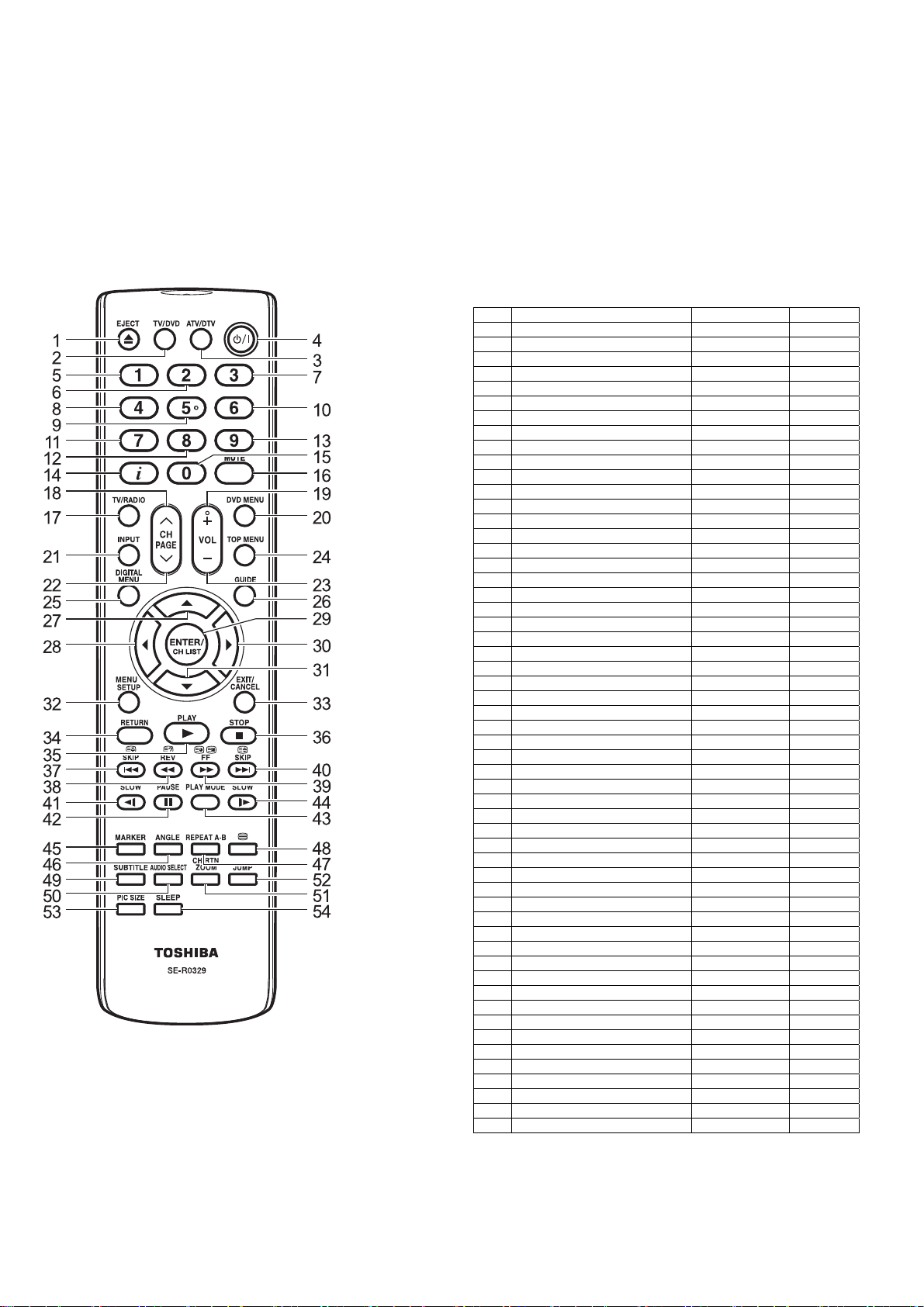
Remote Control Key Codes
Notes:
1. NEC Format
2. Custom Code: 40-BF H, 44-BB H, 45-BA H,
No. Key Name Custom Code Key Code
1 EJECT 45-BA F5
2 TV/DVD 45-BC B3
3 ATV/DTV 40-BF 44
4 POWER 40-BF 12
5 1 40-BF 01
6 2 40-BF 02
7 3 40-BF 03
8 4 40-BF 04
9 5 40-BF 05
10 6 40-BF 06
11 7 40-BF 07
12 8 40-BF 08
13 9 40-BF 09
14 DISPLAY 40-BF 1C
15 0 40-BF 00
16 MUTE 40-BF 10
17 TV/RADIO 40-BF 47
18 CH UP 40-BF 3E
19 VOL+ 40-BF 1A
20 DVD MENU 40-BF 19
21 INPUT 40-BF 0F
22 CH DOWN 40-BF 3F
3F VOL - 40-BF 1E
24 TOP MENU 44-BB DF
25 DIGITAL MENU 40-BF 0A
26 GUIDE 40-BF 45
27 UP 44-BB 80
28 LEFT 44-BB 51
29 ENTER/CH LIST 40-BF 3D
30 RIGHT 44-BB 4D
31 DOWN 44-BB 81
32 MENU SETUP 40-BF 0E
33 EXIT / CANCEL 44-BB EF
34 RETURN 44-BB 5D
35 PLAY 44-BB 15
36 STOP 44-BB 14
37 |<< SKIP 45-BA 23
38 << REV 45-BA 19
39 FF >> 45-BA 13
40 SKIP >>| 45-BA 24
41 SLOW <| 45-BA 0E
42 PAUSE 45-BA 15
43 PLAY MODE 45-BA E0
44 SLOW |> 45-BA 0D
45 MARKER 45-BA EC
46 ANGLE 44-BB 96
47 REPEAT A-B 44-BB 5C
48 TELETEXT 45-BA 79
49 SUBTITLE 44-BB 87
No. Key Name Custom Code Key Code
50 AUDIO SELECT 44-BB 53
51 CH RTN ZOOM 45-BA 40
52 JUMP 44-BB 9B
53 PIC SIZE 40-BF 59
54 SLEEP 40-BF 15
45-BC H
7
Page 8
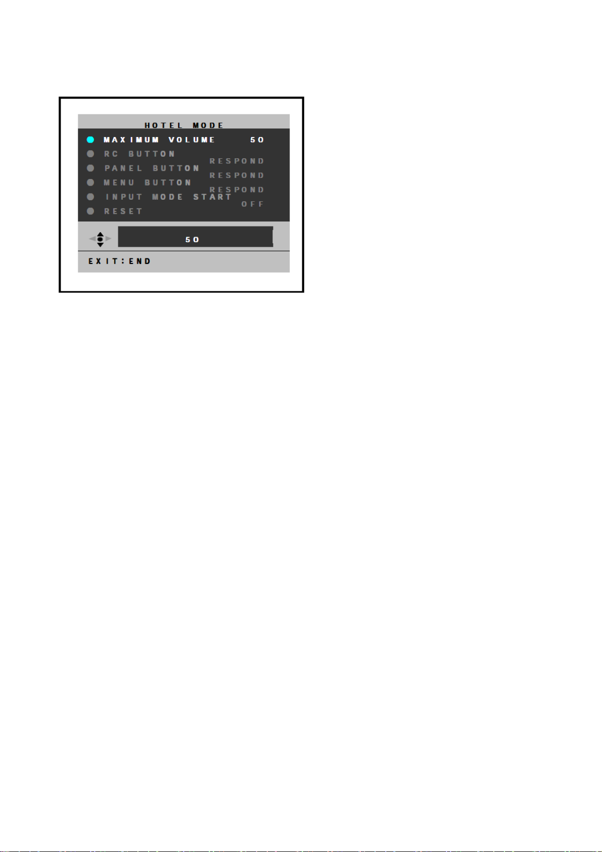
Hotel Mode Function
To set the Hotel mode, please follow the steps below:
1. In power on mode, set the VOLUME to minimum.
Press and hold the VOLUME DOWN button on the side panel.
2. Simultaneously press and hold the channel button (7) on the remote control for more than
2 seconds.
The Hotel mode setting menu will appear.
3. Using the UP/DOWN button on the remote control, select RESET. Then press the ENTER
button.
4. Using the LEFT/RIGHT button on the remote control, set the item to the desired setting.
The Hotel mode has now been set up.
To reset the Hotel mode, please follow the steps below:
1. In power on mode, set the VOLUME to minimum.
Press and hold the VOLUME DOWN button on the side panel.
2. Simultaneously press and hold the channel button (7) on the remote control for more than
2 seconds.
The Hotel mode setting menu will appear.
3. Using the UP/DOWN button on the remote control, select RESET. Then press the ENTER
button.
The setting items have now been returned to initial value.
Page 9
Setting item Setting value Initial value Function
Maximum
volume
RC button RESPOND/
Panel button Effective/invalid setting of main key operation (Note
Menu button Effective/invalid setting of menu, DTV menu and
Input mode start 1-99ch/DTV/AV1/AV2/
Reset - - Various setting of the Hotel mode function returns
Notes:
1. Even if set to “No Respond”, the remote control key operation in Hotel mode and service mode function
are effective.
2. Even if set to “No Respond”, the service mode function is effective.
3. If set to “Off”, it starts up in the same input source before you turn off the power.
0-50 50 Setting of the maximum volume value.
RESPOND Effective/invalid setting of remote control key
NO RESPOND
OFF Setting of input source at power supply On. (Note
COMPONENT/HDMI/
PC/DVD/OFF
operation (Note 1).
2).
GUIDE keys operation of set and remote control
(Note 1).
3)
initial state.
9
Page 10

4. System Disassembly
Disassembly Tools
The following tools are required for disassembling the system.
Wrist-grounding strap and conductive mat for preventing electrostatic discharge
Philips screwdriver
Hex screwdriver
Disassembly Reminders
Electrostatic Discharge (ESD) precautions should be observed to prevent damaging the
internal components.
Follow the sequence indicated in the illustrative figures when removing the screws
securing the components.
The screws for the different components vary in size. During the disassembly process,
group the screws with their corresponding components to avoid mismatches when putting
back the components.
After removing the adhesive tapes, paste them back near their original location for use
during system reassembly.
Prior to disassembly, place the LCD TV on a stable, level surface protected by a cushion.
10
Page 11
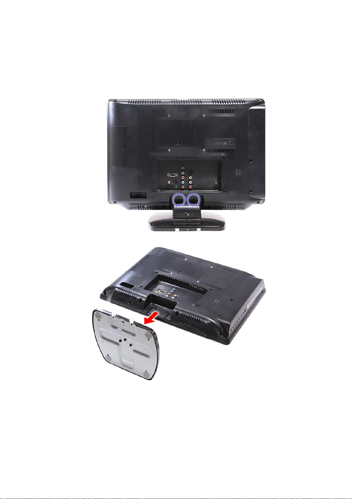
15SLDT3R
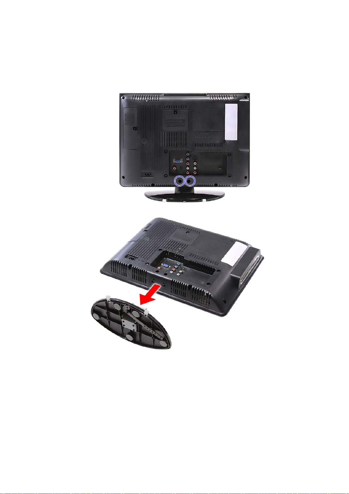
1. Lay down the LCD TV on a flat, stable surface with the rear cover facing up. Make sure
the lip edge of the front bezel is hanging over the edge of the surface.
2. Remove the screws securing the LCD TV base
3. Remove LCD TV base.
11
Page 12
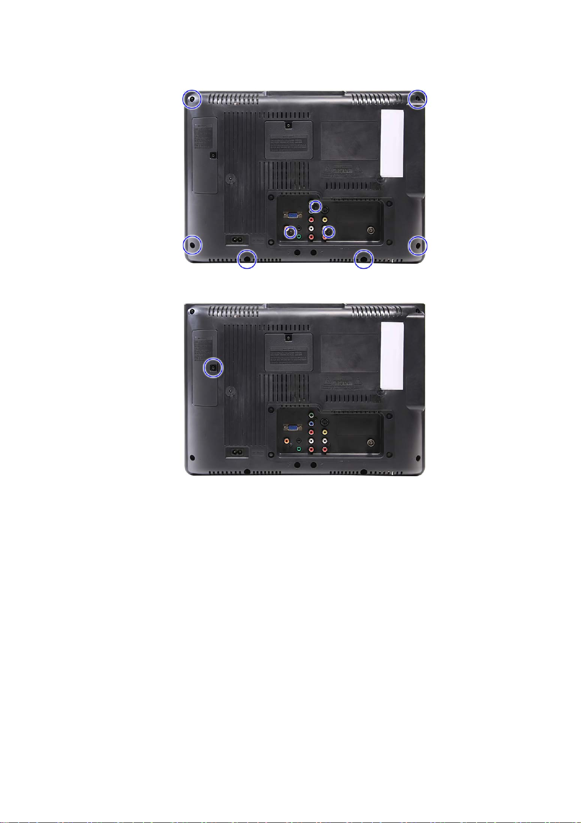
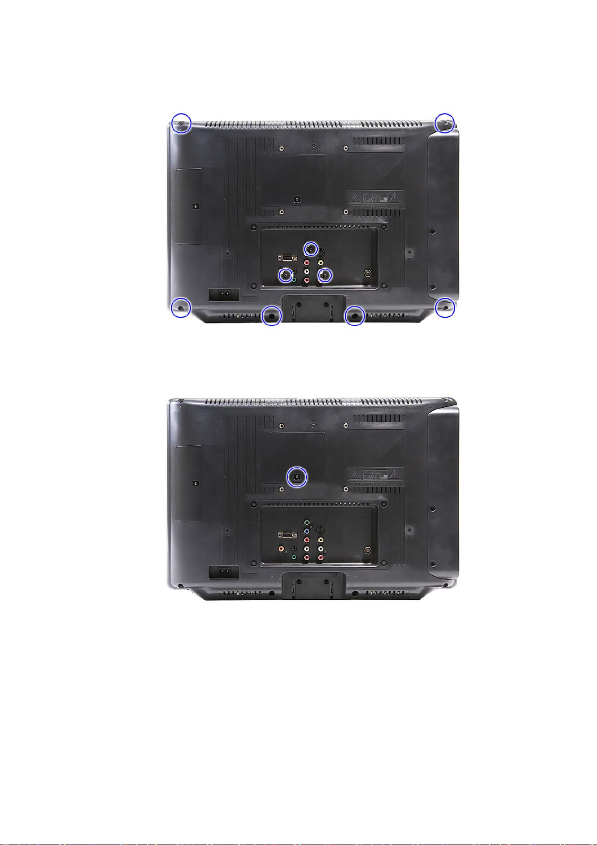
4. Remove the screws securing the rear panel cover.
5. Remove the screw securing the left rear panel door.
12
Page 13
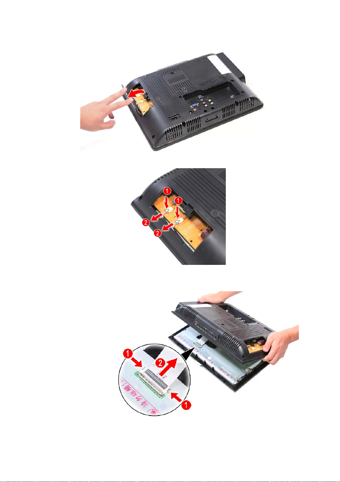
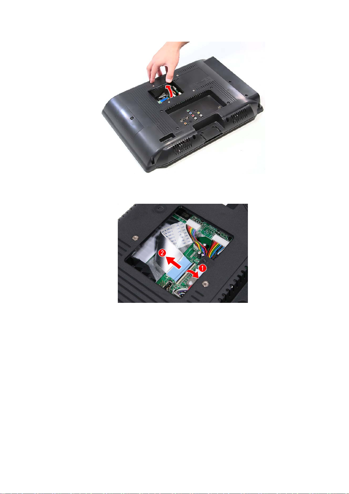
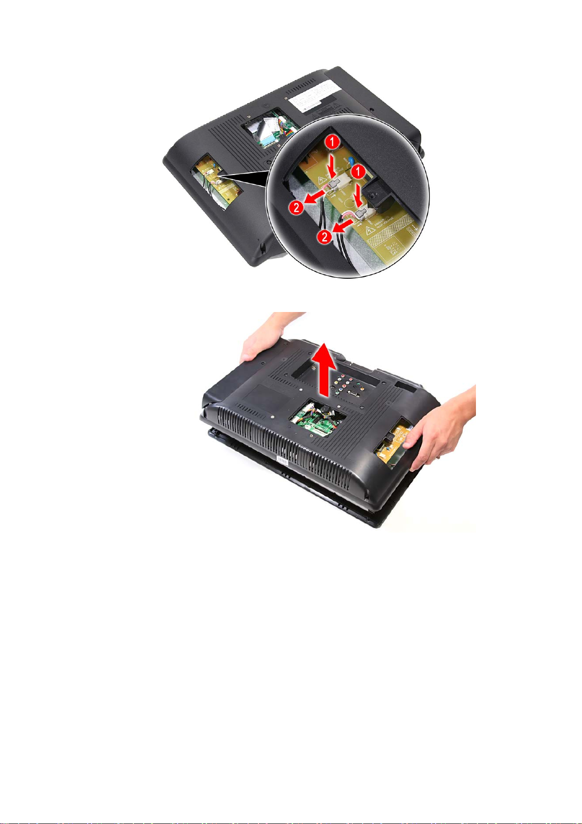
6. Open and remove the left rear panel door.
7. Disconnect the power cables.
8. Detach the top part of the rear panel cover from the housing and tilt it back to expose the
LCD cable on the LCD panel; then disconnect the LCD cable, and remove the rear panel.
Caution: As FFC connector for LCD panel can easily be damaged during disassembly or reassembly, handle
it with care.
13
Page 14
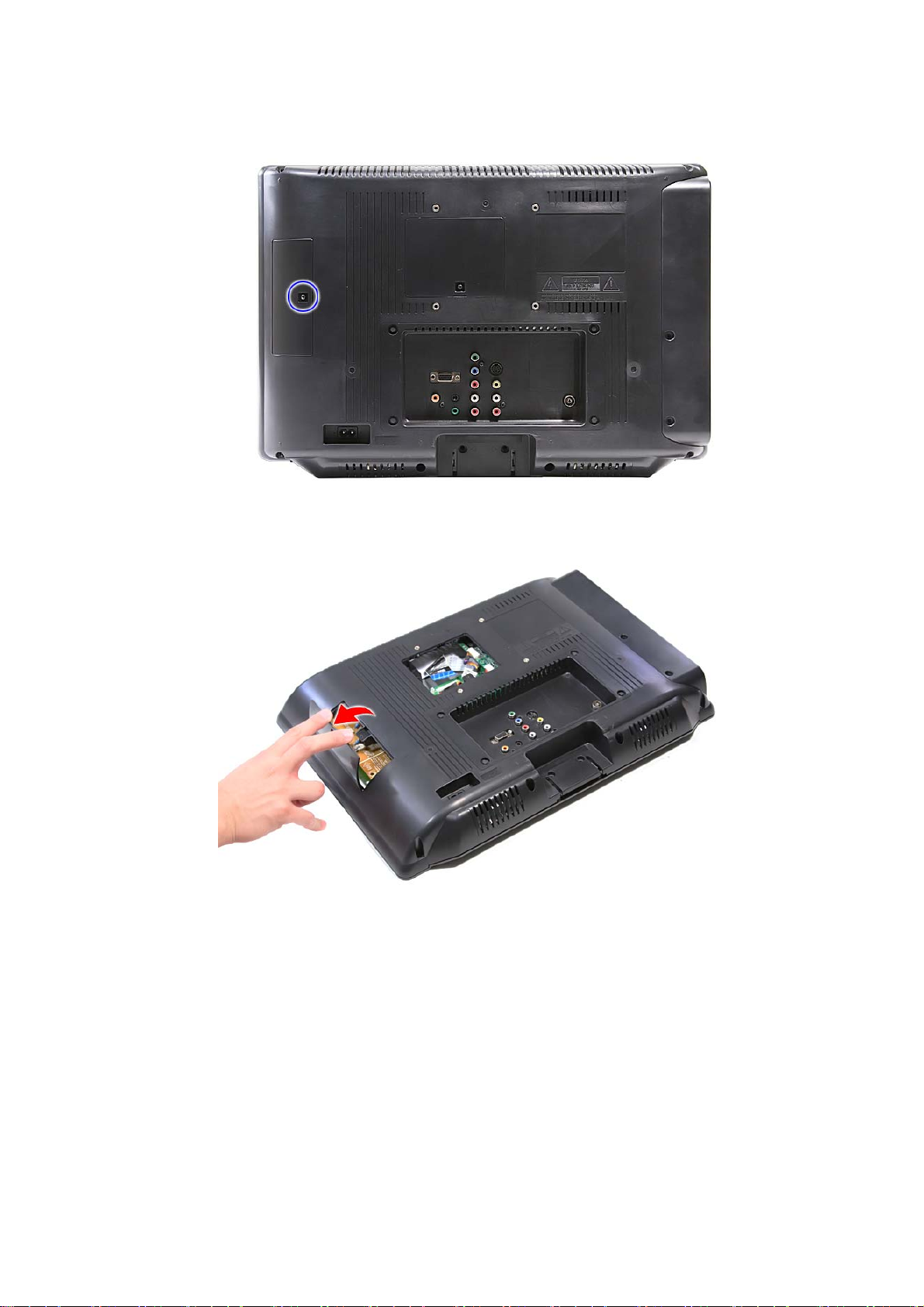
e: Take note of the spring orientation when reassembling the TV.
Not
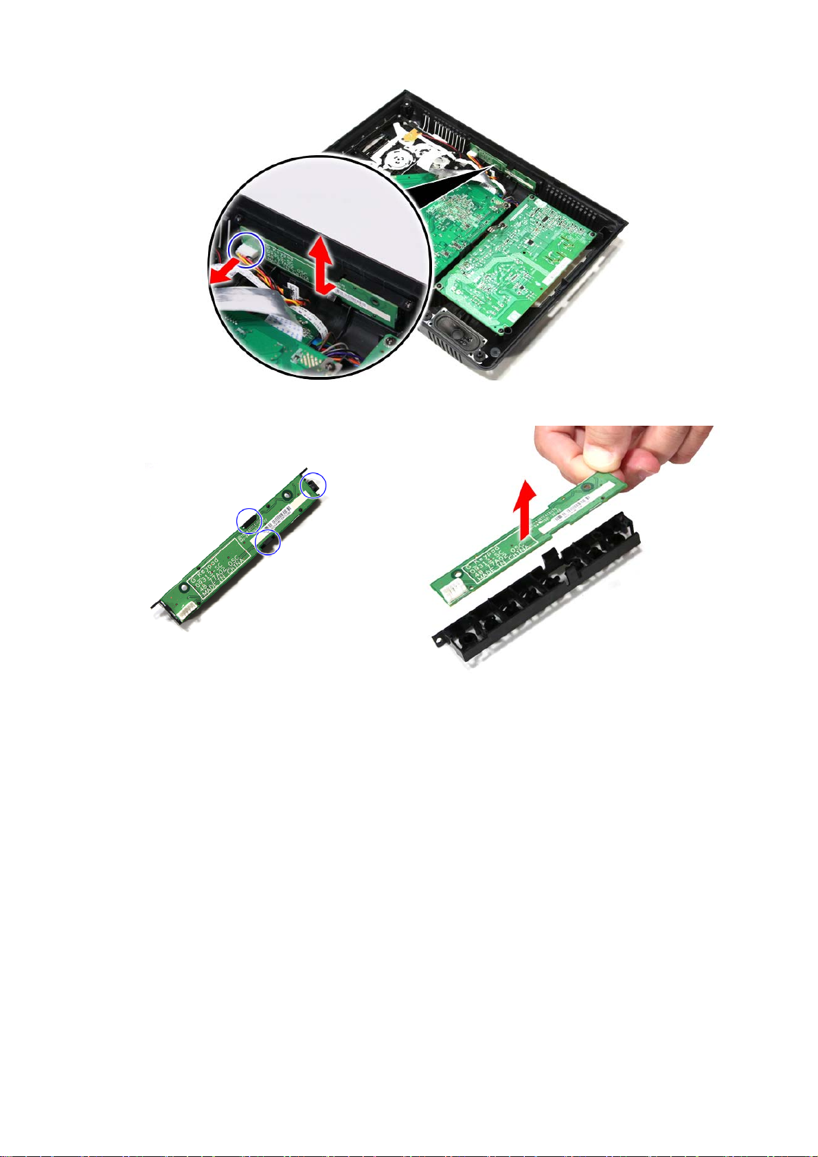
9. Remove the screws securing the IR board.
14
Page 15
10. Disconnect the cable from the LED board; then pull up to remove the IR board.
11. Remove the screws from the control board.
15
Page 16
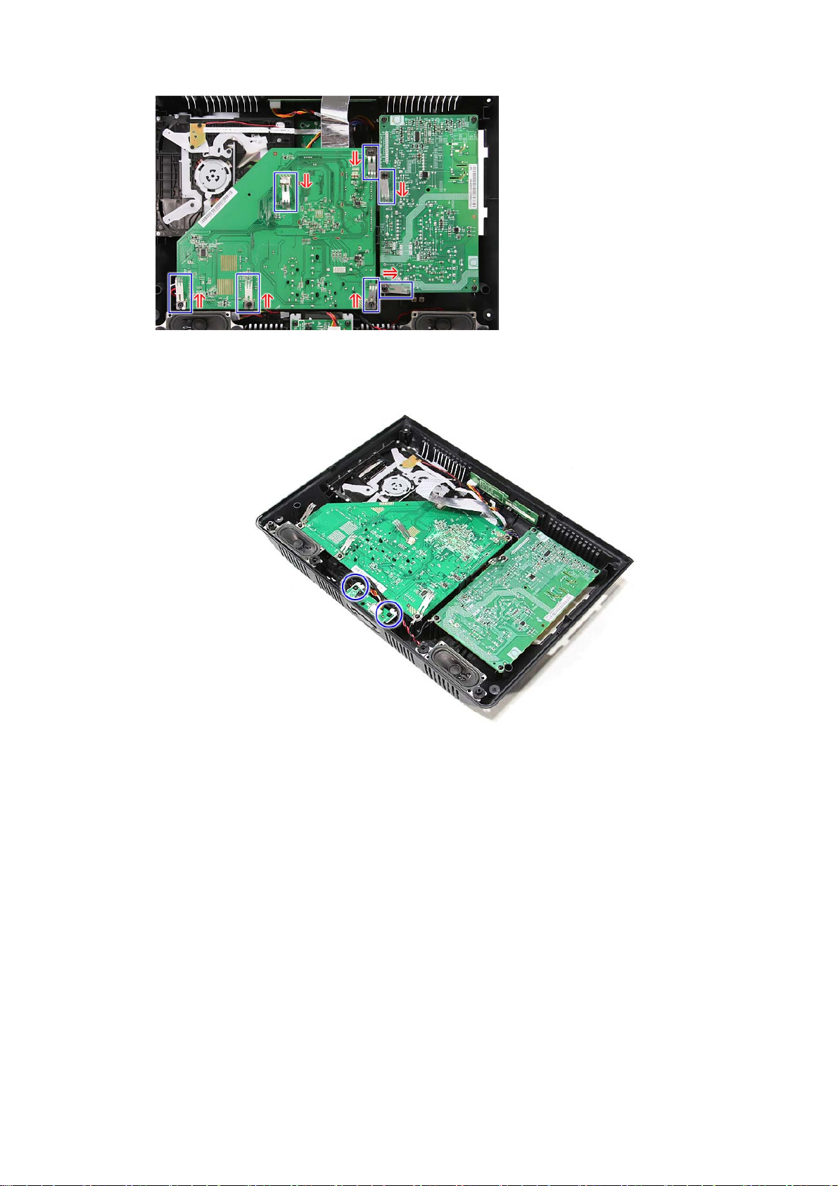
12. Disconnect the cable from the control board; then remove the control board.
13. Unlatch the control board from its plastic bracket to separate it from its case.
16
Page 17
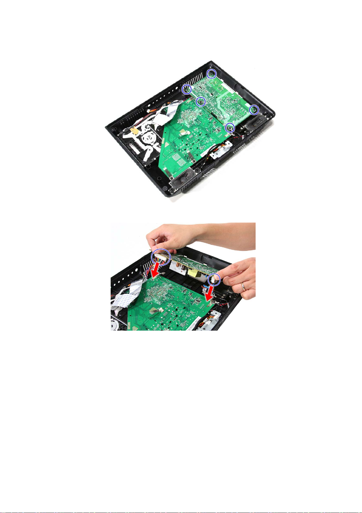
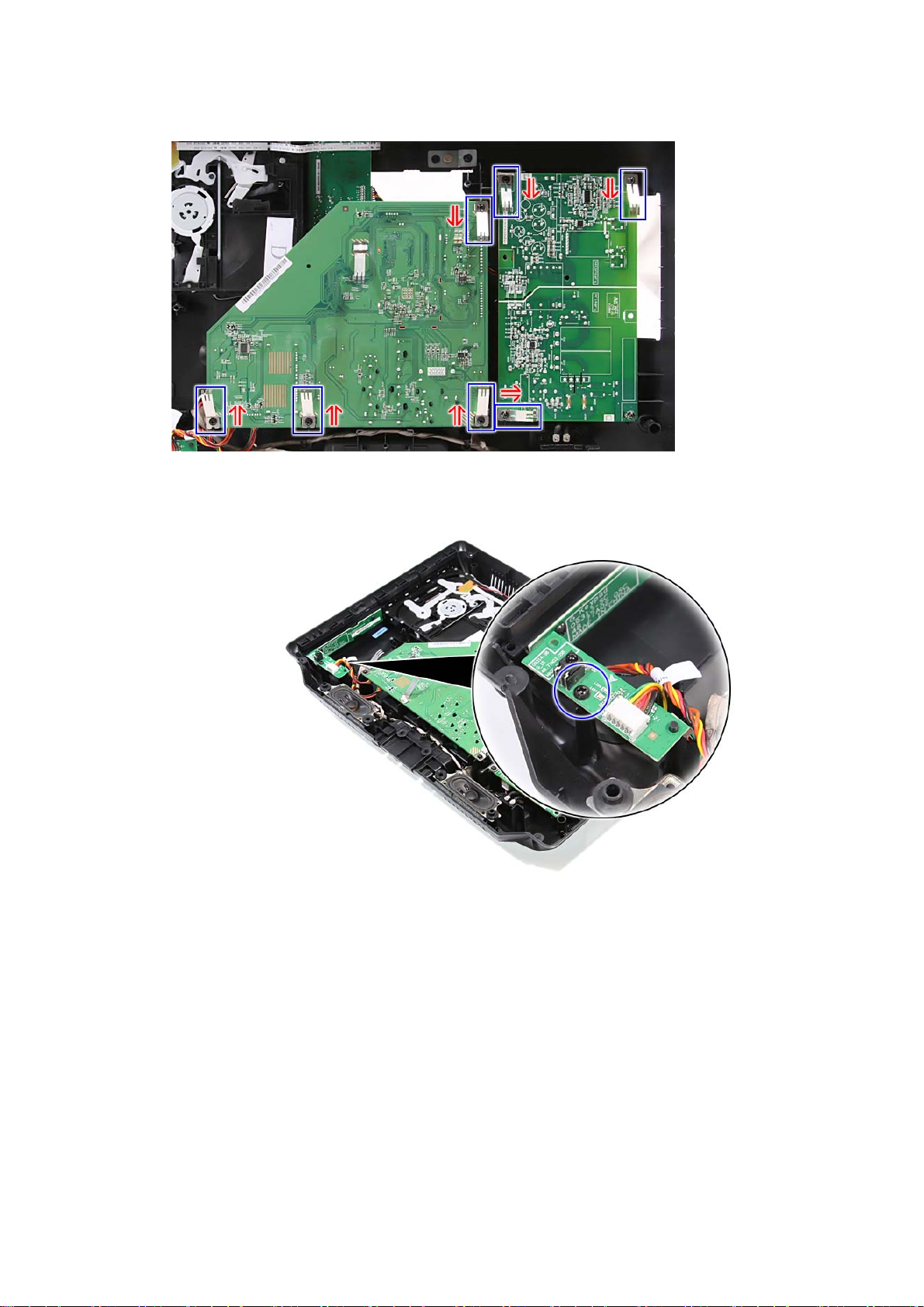
14. Remove the screws securing the power board.
15. Lift up the power board at an angle; then disconnect the two cables, and remove the
power board.
.
17
Page 18
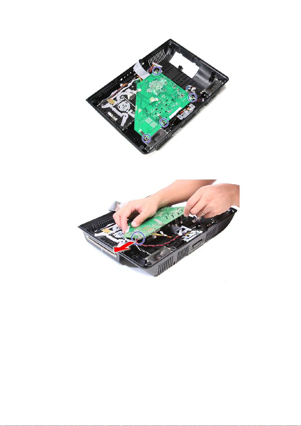
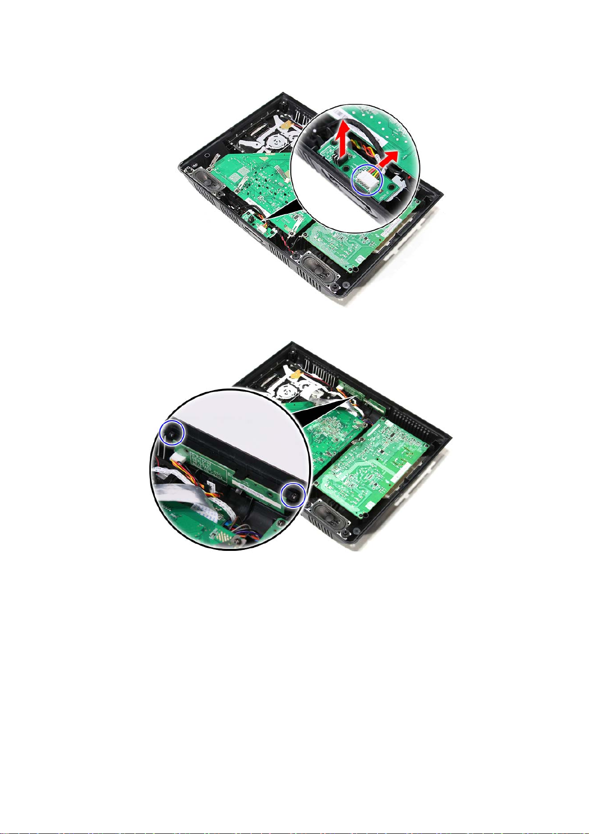
16. Remove the screws securing the mainboard.
17. Lift the mainboard at an angle; then disconnect the cable.
18
Page 19
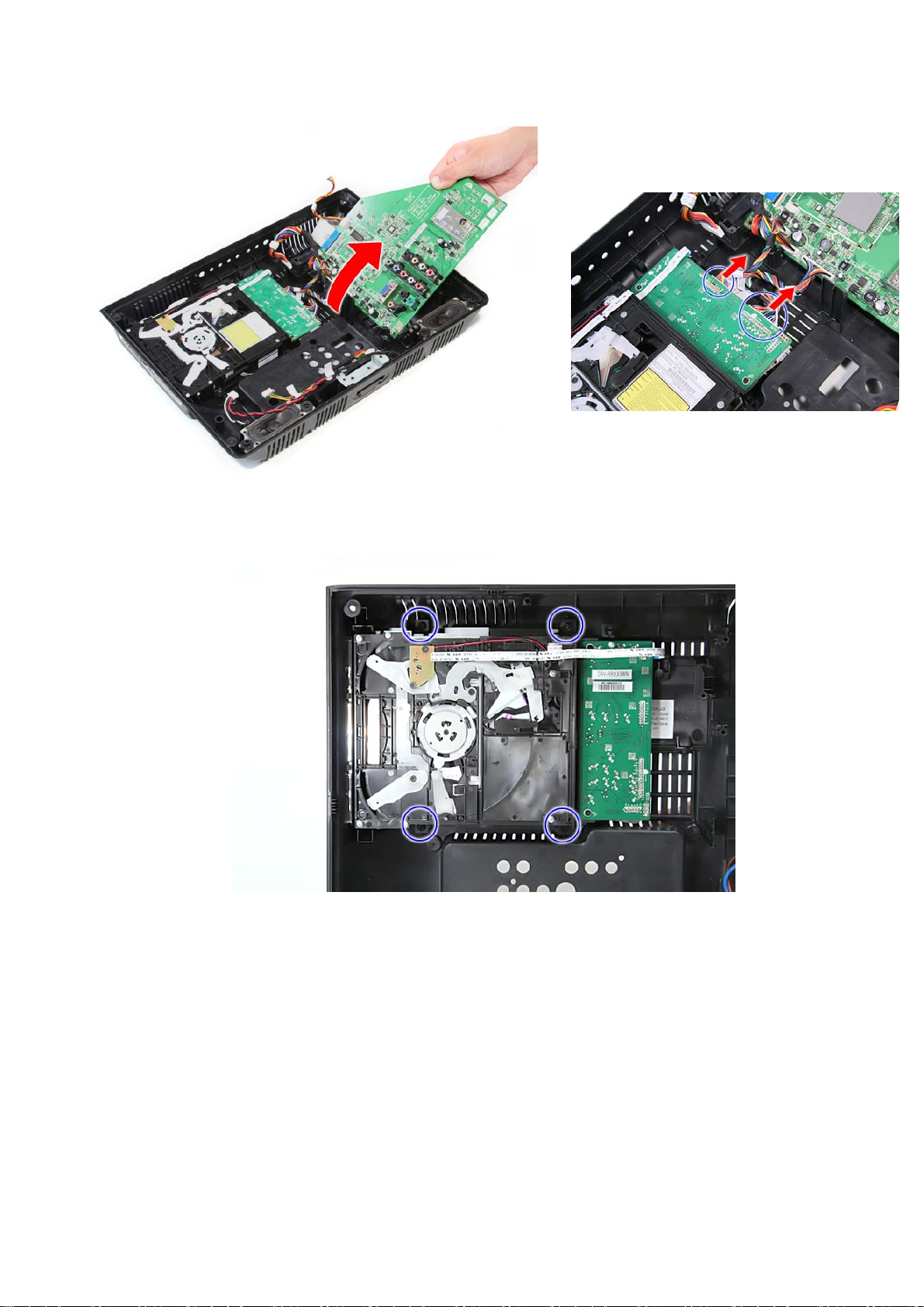
18. Lift up the mainboard; then disconnect the two cables.
19. Remove the screws securing the optical drive.
19
Page 20
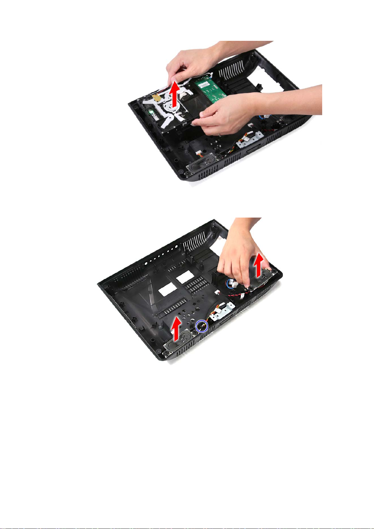
20. Lift up and remove the optical drive.
21. Pull up to release the left and right speakers. Take note to release the speaker cables
from their latch.
20
Page 21
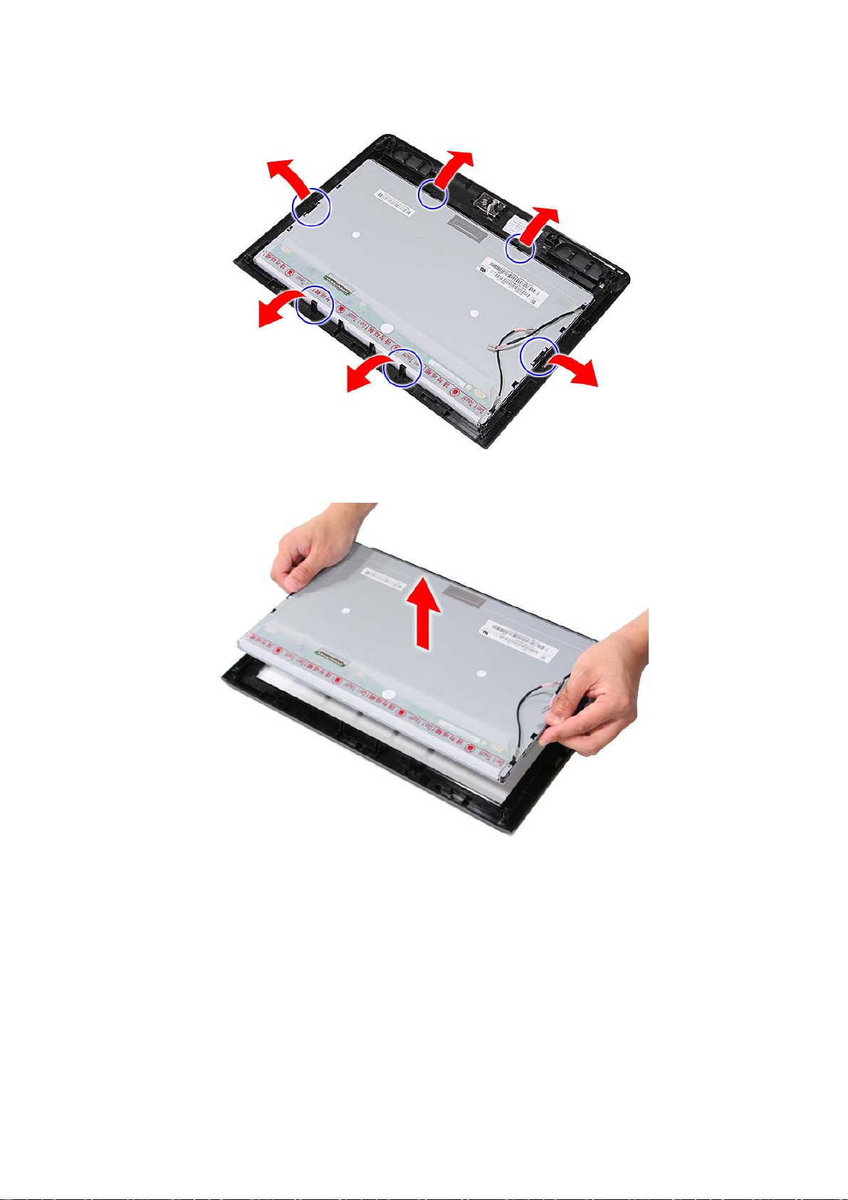
22. Release the LCD panel from its latches.
23. Remove the LCD panel from the front bezel.
21
Page 22
19SLDT3R
1. Lay down the LCD TV on a flat, stable surface with the rear cover facing up. Make sure
the lip edge of the front bezel is hanging over the edge of the surface.
2. Remove the screws securing the LCD TV base
3. Remove LCD TV base.
22
Page 23
4. Remove the screws securing the rear panel cover.
5. Remove the screw securing the center rear panel door.
23
Page 24
6. Open and remove the center rear panel door.
7. Disconnect the LCD cable.
Caution: As FFC connector for LCD panel can easily be damaged during disassembly or reassembly, handle
it with care.
24
Page 25
8. Remove the screw securing the left rear panel door.
9. Open and remove the left rear panel door.
25
Page 26
10. Disconnect the power cables.
11. Detach the top part of the rear panel cover from the housing, and remove the rear panel.
26
Page 27
Note: Take note of the spring orientation when reassembling the TV.
12. Remove the screw securing the IR board.
27
Page 28

13. Pull up to remove the IR board; then disconnect the cable from the IR board.
14. Remove the screws securing the control board.
28
Page 29

15. Disconnect the cable from the control board; then remove the control board.
16. Unlatch the control board from its plastic bracket to separate it from its case.
29
Page 30

17. Remove the screws securing the power board.
18. Turn the power board over; then disconnect the two cables, and remove the power board.
30
.
Page 31

19. Remove the screws securing the mainboard.
20. Lift the mainboard at an angle; then disconnect the speaker cable.
31
Page 32

21. Turn the mainboard over; then disconnect the two cables.
22. Remove the screws securing the optical drive.
23. Lift up and remove the optical drive.
24. Pull up to release the left and right speakers. Take note to release the speaker cables
32
Page 33

from their latches.
25. Remove the LCD panel from the front bezel.
33
Page 34

22SLDT3R
1. Lay down the LCD TV on a flat, stable surface with the rear cover facing up. Make sure
the lip edge of the front bezel is hanging over the edge of the surface.
2. Remove the screws securing the LCD TV base
3. Remove LCD TV base.
34
Page 35

4. Remove the screws securing the rear panel cover.
5. Remove the screw securing the center rear panel door.
35
Page 36

6. Open and remove the center rear panel door.
7. Disconnect the LCD cable.
Caution: As FFC connector for LCD panel can easily be damaged during disassembly or reassembly, handle
it with care.
36
Page 37

8. Remove the screw securing the left rear panel door.
9. Open and remove the left rear panel door.
37
Page 38

10. Disconnect the power cables.
11. Detach the top part of the rear panel cover from the housing, and remove the rear panel.
Note: Take note of the spring orientation when reassembling the TV.
38
Page 39

12. Pull up to remove the IR board; then disconnect the cable from the IR board.
13. Remove the screws securing the control board.
39
Page 40

14. Disconnect the cable from the control board; then remove the control board.
15. Unlatch the control board from its plastic bracket to separate it from its case.
16.
40
Page 41

17. Remove the screws securing the power board.
18. Turn the power board over; then disconnect the two cables, and remove the power board.
.
41
Page 42

19. Remove the screws securing the mainboard.
20. Lift the mainboard at an angle; then disconnect the speaker cable.
42
Page 43

21. Turn the mainboard over; then disconnect the two cables.
22. Remove the screws securing the optical drive.
43
Page 44

23. Lift up and remove the optical drive.
24. Pull up to release the left and right speakers. Take note to release the speaker cables
from their latches.
25. Remove the LCD panel from the front bezel.
44
Page 45

45
Page 46

26SLDT3R
1. Lay down the LCD TV on a flat, stable surface with the rear cover facing up. Make sure
the lip edge of the front bezel is hanging over the edge of the surface.
2. Remove the screws securing the LCD TV base
3. Remove LCD TV base.
46
Page 47

4. Remove the screws securing the rear panel cover.
5. Remove the screw securing the left rear panel door.
47
Page 48

6. Open and remove the left rear panel door.
7. Disconnect the power cable.
48
Page 49

8. Remove the screw securing the center rear panel door.
9. Open and remove the center rear panel door.
49
Page 50

10. Disconnect the LCD cable.
Caution: As FFC connector for LCD panel can easily be damaged during disassembly or reassembly, handle
it with care.
11. Detach the top part of the rear panel cover from the housing, and remove the rear panel.
50
Page 51

Note: Take note of the spring orientation when reassembling the TV.
12. Disconnect the cable from the IR board.
13. Remove the IR board by releasing it from its latches.
51
Page 52

14. Remove the screws securing the control board.
15. Disconnect the cable from the control board; then remove the control board.
52
Page 53

16. Unlatch the control board from its plastic bracket to separate it from its case.
17. Remove the screws securing the power board.
53
Page 54

18. Turn the power board over; then disconnect the two cables, and remove the power board.
.
19. Remove the screws securing the mainboard.
54
Page 55

20. Release the cables from their latches.
21. Lift up the mainboard at an angle and disconnect the speaker cable.
55
Page 56

22. Turn the mainboard over; then disconnect the two cables.
23. Remove the screws securing the optical drive.
56
Page 57

24. Lift up and remove the optical drive.
25. Pull up to release the left and right speakers. Take note to release the speaker cables
from their latches.
57
Page 58

26. Remove the screws securing the LCD bracket to the LCD panel.
27. Remove the LCD bracket from the front bezel.
58
Page 59

28. Remove the LCD panel from the front bezel.
59
Page 60

5. Exploded Diagram
15SLDT3R
<to be provided>
60
Page 61

Parts List: 15SLDT3R
Loca tion TSB P/N. Reference No. Description
1 AJ000129 90.70G11.001 RC RUSSIA EU ANALOG SE-R0319
2 AJ000130 91.72J10.002G IR BD LCD TV RUSSIA PACKING MP
3 AJ000106 91.76A10.005G KP BD LCD TV GAUGEU PACKING MP
4 AJ000005 50.77A27.001 C.A. IR-LED-GL-G15
5 AJ000006 50.77A30.001 C.A. DVD-SIGNAL-GL-G15
6 AJ000007 50.77A40.001 C.A. 2P-AC-INLET-GL-G15
7 AJ000008 50.77A26.001 C.A. MB-LIPS-GL-G15
8 AJ000009 50.77A25.001 C.A. FFC-LVDS-JH-G15
9 AJ000131 50.77A35.001 C.A. SPEAKER-GRU-GL-G15
10 AJ000011 50.77A29.001 C.A. DVD-POWER-GL-G15
11 AJ000012 50.77A28.001 C.A. KEYPAD-GL-G15
12 AJ000013 50.77A41.001 C.A. PSU-GROUND-GL-G15
13 AJ000132 27.01518.G51 CORD 2.5A 250V 2P2P EU/R BLACK
14 AJ000015 33.77A10.001 BRKT-BOTTOM-G15
15 AJ000022 42.77A28.001 CVR-DOOR-LIPS-G15
16 AJ000133 60.72J08.002 ASSY-CVR-BACK-GRU-G15
17 AJ000127 42.77A09.011 KNOB KEY-FS-G15-G26
18 AJ000134 60.72J07.001 ASSY-BEZEL-FRONT-GRU-G15
19 AJ00015 8 G8CD00000120 DVD HH SLOT DAV-RR933WR
20 AJ000026 60.77A15.001 ASSY-STAND-G15
21 AJ000135 91.72J10.003G MB GRU15 PACKING -1
22 AJ00002 9 56.04050.171 LIPS 50W DPS-50UP A 01 GAT15
23 AJ000099 34.00015.071 SCRW HEX I#4-40/O#4-40 L5.5 NI
24 AJ000136 86.WAX83.8R0 SCRW T2.5X0.5 8L BLACK ZN
25 AJ000030 86.1B326.100 SCRW M PAN M4*10L PM+SP BLK ZN
26 AJ000031 86.CA214.8R0 SCRW T3X0.5 8L BLACK ZN 2LEAD
27 AJ000032 86.Y1214.120 SCRW T3X0.5 12L BLACK ZN 2LEAD
28 AJ000034 86.VA314.6R0 SCREW M3 6L P T BLACK ZN
29 AJ000035 23.40607.001 SPEAKER_GRACE_GAT-15-19-22
32 *** CUS HION ***
30 *** OWNER’S MANUAL ***
31 *** CARTON BOX ***
SAFETY PRECAUTION
The parts identified by mark are critical for safety. Replace only with part number specified. The
mounting position of replacement is to be identical with originals.
The substitute replacement parts which do not have the same safety characteristics as specified in the
parts list may create shock, fire or other hazards.
61
Page 62

19SLDT3R
<to be provided>
62
Page 63

Parts List: 19SLDT3R
Loca tion TSB P/N. Reference No. Description
1 AJ000129 90.70G11.001 RC RUSSIA EU ANALOG SE-R0319
2 AJ000130 91.72J10.002G IR BOARD
3 AJ000106 91.76A10.005G KP BD LCD TV GAUGEU PACKING MP
4 AJ000039 50.77A17.001 C.A.14-13P-DVD-SIGNAL-GL-G19
5 AJ000041 50.77A39.001 C.A.2P-AC-INLET-GL-G19
6 AJ000132 27.01518.G51 CORD 2.5A 250V 2P2P EU/R BLACK
7 AJ000038 50.77A15.001 C.A.6-6P-IR-LED-GL-G15-19-22
8 AJ000044 50.77A16.001 C.A.8-8P-DVD-POWER-GL-G19-22
9 AJ000042 50.77A23.001 C.A.-FFC-30-30-JH-G19
10 AJ000040 50.77A33.001 C.A.14P-PSU-GL-G19
11 AJ000138 50.72J01.001 C.A.4P-SPEKER-GRU-GL-G9
12 AJ000045 50.77A37.001 C.A. MB-KEY-GL-G26
13 AJ000049 60.77A10.001 ASSY-CVR-DVD-G22
14 AJ000052 42.77A09.001 KEY-G26
15 AJ000047 42.77A11.001 CVR-DOOR-LVDS-G22
16 AJ000053 42.77A20.001 CVR-LIPS-G19
17 AJ000140 60.72J02.003 ASSY-CVR-BACK-RUS-G19
18 AJ000142 60.72J09.001 ASSY-BEZEL-FRONT-GRU-G19
19 AJ00015 8 G8CD00000120 DVD HH SLOT DAV-RR933WR
20 AJ000054 60.77A11.001 ASSY-STAND-BASE-G22
21 AJ000144 91.72J10.001G MB GRU15_22 PACKING -1
22 AJ000115 56.04050.G21 LIPS 50W FSP050- 2PI06 REV:1.02
23 AJ000102 86.CA516.140 SCRW T4X0.7 14L SILV NI 2LEAD
24 AJ000096 86.CA514.8R0 SCRW T3X0.5 8L SILV NI 2LEAD
25 AJ000136 86.WAX83.8R0 SCRW T2.5X0.5 8L BLACK ZN
26 AJ000099 34.00015.071 SCRW HEX I#4-40/O#4-40 L5.5 NI
27 AJ000030 86.1B326.100 SCRW M PAN M4*10L PM+SP BLK ZN
28 AJ000100 86.6AI34.5R0 SCRW-MACH-ROUND-M3*5L-BLACK
29 AJ000031 86.CA214.8R0 SCRW T3X0.5 8L BLACK ZN 2LEAD
30 AJ000058 86.CA216.140 SCRW T4X0.7 14L BLACK ZN 2LEAD
31 AJ000035 23.40607.001 SPEAKER_GRACE_GAT-15-19-22
33 *** CARTON BOX ***
32 *** OWNER’S MANUAL ***
34 *** CUSHION ***
SAFETY PRECAUTION
The parts identified by mark are critical for safety. Replace only with part number specified. The
mounting position of replacement is to be identical with originals.
The substitute replacement parts which do not have the same safety characteristics as specified in the
parts list may create shock, fire or other hazards.
63
Page 64

22SLDT3R
<to be provided>
64
Page 65

Parts List: 22SLDT3R
Loca tion TSB P/N. Reference No. Description
1 AJ000137 90.70G11.002 RC RUSSIA EU ANALOG SE-R0337
2 AJ000130 91.72J10.002G IR BD LCD TV RUSSIA PACKING MP
3 AJ000106 91.76A10.005G KP BD LCD TV GAUGEU PACKING MP
4 AJ000039 50.77A17.001 C.A.14-13P-DVD-SIGNAL-GL-G19
5 AJ000061 50.77A18.001 C.A. LVDS-FFC-JH-G22
6 AJ000059 50.77A21.001 C.A. 2P-AC-INLET-GL-G22
7 AJ000132 27.01518.G51 CORD 2.5A 250V 2P2P EU/R BLACK
8 AJ000038 50.77A15.001 C.A.6-6P-IR-LED-GL-G15-19-22
9 AJ000044 50.77A16.001 C.A.8-8P-DVD-POWER-GL-G19-22
10 AJ000060 50.77A19.001 C.A.14P-PSU-GL-G22
11 AJ000145 50.77A32.011 C.A.4P-SPEKER-GEU-HT-G22
12 AJ000045 50.77A37.001 C.A. MB-KEY-GL-G26
13 AJ000052 42.77A09.001 KEY-G26
14 AJ000047 42.77A11.001 CVR-DOOR-LVDS- G22
15 CVR-LIPS- G19
16 ASSY-BEZEL-FRONT-G22-RU
17 ASSY-CVR-DVD- G22
18 ASSY-CVR-BACK-GRU- G22
19 AJ00015 8 G8CD00000120 DVD HH SLOT DAV-RR933WR
20 ASSY-STAND-BASE- G22
21 AJ000144 91.72J10.001G MB GRU15_22 PACKING -1
22 AJ000150 56.04065.631 LIPS 65W UA-2600-1-LF REV: 02
23 AJ000099 34.00015.071 SCRW HEX I#4-40/O#4-40 L5.5 NI
24 AJ000136 86.WAX83.8R0 SCRW T2.5X0.5 8L BLACK ZN
25 AJ000101 86.CA514.100 SCRW T3X0.5 10L SILV NI 2LEAD
26 AJ000096 86.CA514.8R0 SCRW T3X0.5 8L SILV NI 2LEAD
27 AJ000102 86.CA516.140 SCRW T4X0.7 14L SILV NI 2LEAD
28 AJ000035 23.40607.001 SPEAKER_GRACE_GAT-15-19-22
30 *** CARTON BOX ***
29 *** OWNER’S MANUAL ***
31 *** CUSHION ***
SAFETY PRECAUTION
The parts identified by mark are critical for safety. Replace only with part number specified. The
mounting position of replacement is to be identical with originals.
The substitute replacement parts which do not have the same safety characteristics as specified in the
parts list may create shock, fire or other hazards.
65
Page 66

26SLDT3R
<to be provided>
66
Page 67

Parts List: 26SLDT3R
Loca tion TSB P/N. Reference No. Description
1 AJ000129 90.70G11.001 RC RUSSIA EU ANALOG SE-R0319
2 AJ000130 91.72J10.002G IR BD LCD TV RUSSIA PACKING MP
3 AJ000106 91.76A10.005G KP BD LCD TV GAUGEU PACKING MP
4 AJ000039 50.77A17.001 C.A.14-13P-DVD-SIGNAL-GL-G19
5 AJ000132 27.01518.G51 CORD 2.5A 250V 2P2P EU/R BLACK
6 AJ000076 50.77A01.011 C.A. MB-IR-HT-G26
7 AJ000077 50.77A03.011 C.A. PSU-INV-HT-G26
8 AJ000078 50.77A04.011 C.A. PSU-AC-HT-G26
9 AJ000079 50.77A05.011 C.A. MB-POWER-HT-G26
10 AJ000151 50.77A07.002 C.A. MB-LVDS-JH-G26
11 AJ000152 50.76A01.011 C.A. MB-SPK-HT-GEU26
12 AJ000044 50.77A16.001 C.A.8-8P-DVD-POWER-GL-G19-22
13 AJ000082 50.77A37.011 C.A. MB-KEY-HT-G26
14 AJ000084 33.77A01.001 BRKT-BTM-G26
15 AJ000052 42.77A09.001 KEY-G26
16 AJ000047 42.77A11.001 CVR-DOOR-LVDS-G22
17 AJ000153 60.72J01.002 ASSY-CVR-BACK-GRU-G26
18 AJ000086 60.77A02.001 ASSY-CVR-DVD-GAT-G26
19 AJ000154 60.72J06.001 ASSY-BEZEL-FRONT-G26D
20 AJ00015 8 G8CD00000120 DVD HH SLOT DAV-RR933WR
21 AJ000089 60.77A03.001 ASSY-CVR-STAND-G26
22 AJ000155 91.72J10.C01G MB GRU26 PACKING -1
23 AJ000126 56.04128.G21 SPS 128W PFC FSP128-3F01-R2 GA
24 AJ000136 86.WAX83.8R0 SCRW T2.5X0.5 8L BLACK ZN
25 AJ000099 34.00015.071 SCRW HEX I#4-40/O#4-40 L5.5 NI
26 AJ000030 86.1B326.100 SCRW M PAN M4*10L PM+SP BLK ZN
27 AJ000031 86.CA214.8R0 SCRW T3X0.5 8L BLACK ZN 2LEAD
28 AJ000058 86.CA216.140 SCRW T4X0.7 14L BLACK ZN 2LEAD
29 AJ000075 86.CA234.100 SCRW T3X0.5 10L BLACK ZN 2LEAD
30 AJ000156 23.40682.011 SPEAKER-GRACE26-L-KOKA
31 AJ000157 23.40682.001 SPEAKER-GRACE26-R-KOKA
33 *** CARTON BOX ***
32 *** OWNER’S MANUAL ***
34 *** CUSHION ***
SAFETY PRECAUTION
The parts identified by mark are critical for safety. Replace only with part number specified. The
mounting position of replacement is to be identical with originals.
The substitute replacement parts which do not have the same safety characteristics as specified in the
parts list may create shock, fire or other hazards.
67
Page 68

6. Packing diagram
15SLDT3R
68
Page 69

19SLDT3R
69
Page 70

22SLDT3R
70
Page 71

26SLDT3R
71
Page 72

7. Block Diagrams
Sound amp unit
72
Page 73

DVD module
73
Page 74

Power supply unit
74
Page 75

8. Printed Circuit Board
Top
75
Page 76

Bottom
76
Page 77

9. Interconnection diagram
77
Page 78

78
Page 79

79
Page 80

10. Troubleshooting
No Display on Screen (Screen is black, no power)
No Power/No Video
Is TV
plu
gged to
AC outlet?
Yes
Does the power turn
on (LED gr
(19”/22”/26” ; 15”
LED blue) if the
keypad and remote
control are pressed
Check power on Power board
een
No
No
Plug TV power cord to
AC outlet
Yes
Which one is the problem
related to?
Audio Video
80
(5Vsb,12V)
Check power on Main board
No
Power board fail.. Please
change another power BD
Check power, reset, crystal,
flash circuit.
Page 81

)
Power Check step
Power Step check
Does power have
5Vsb?
Yes
NO
Have 3.3Vsb?
Check power BD
NO
Check U208 pin2
Does power
NO
have 12V?
NO
Yes
Have 6V?
NO
Check L242 pin2
Have 9V?
NO
Check L242 pin2
Yes
Have 5V?
NO
Check L212
Yes
Have 3.3V?
Yes
Have 2.5V?
NO
NO
Check U213 (for DVD)
Check U209 (For system
Check U206 (for
Check U205
Have tuner 5V?
81
Page 82

Video problem
Video problem
Is OSD on the
screen
Y
es
Check if signal cable
is connected and
have signal output
No
Check panel power on LVDS
cable:
U202 pin 5,6,7,8 should have
5 Vdc(15”/19”/22”),12V(26”)
Check backlight on/off control:
CN201 pin2 should be 2~5Vdc
RF AV/SV Component
Check tuner CVBS
signal to scaler, I2C,
power and related
circuit.
1. CheckU701#4 for the 5V
2. Check U701#7,8 for I2C check
1. Check C604#1 and C605#2, C
for Y-signal waveform
Check signal
path from
connector to the
scaler
Which input has no
picture?
Check signal path
from connector to the
scaler
1. Check C636#1 for VGA_R
2. Check C637#1 for VGA_G
3. Check C639#1 for VGA_B
4. Check R657#1 for HSYNC
5. Check R663#1 for VSYNC
6102#1
VGA
Check signal path
from connector to the
scaler, especially the
Y signal
1. Check C606#1 for Y
2. Check C607#1 for Pr
3. Check C6084#1 for Pb
82
Page 83

N
Speaker No Sound (Test signal: ≦0.5Vrms @1kHz sine waveform)
Audio Problem
Please ensure the signal cable is connected
and has output and remove the earphone.
No Audio issue
No Audi
o
Have you enabled
MUT
E function
and speaker OFF?
o
Yes
Disable MUTE function from
remote control and increase
Volume
Note: Speaker will be muted when
headphone is plugged.
Check U802 (26”only) power
Pin 6,7,12,
U801(15”/19”/22” only) power
pin# 4,9,16,21=5V
13=12Vdc
s
Ye
Check U801, U802
io input
aud
Yes
Check U801, U802
output signal
s
Ye
No
NO
No
Check power bd 12V
Check equipment output
U801, U802 fail
Check net “MUTE” and “HP”
circuit
83
Page 84

11. Firmware
Checking the LCD TV Firmware Version
Follow these steps:
1. Turn on the LCD TV.
2. Press and hold the Volume – button on the LCD TV, and, at the same time, press and hold
the 8 button on the remote control.
3. After at least 2 seconds, release the buttons to display the firmware information.
LCD PWR ON : xxxx
MCU
CHECK SUM : xxxxxxxxxx
VERSION : Vx.xx.xxx
System F/W
CHECK SUM : xxxxxxxxxx
VERSION : Vx.xx.xxx
4. Press the Exit button on the remote control to close the window.
Updating the LCD TV Firmware
Follow these steps:
1. Turn on a computer and plug in the ISP board to an available USB port.
2. Connect a VGA cable from the ISP board to the VGA connector on the LCD TV.
3. Open the center rear cover to access the service connectors.
4. Locate the connector CN401 and connect it to the ISP board.
5. Run the program spisp_1.34.exe
.
6. Set the COM port to the correct value.
7. Click the Select File button and browse for the system firmware; then click Open.
8. Click the Start button to begin the update process. The following message appears on the
LCD TV screen.
TV FIRMWARE UPDATE...
84
Page 85

9. After the firmware update successfully completes, the following message appears on the LCD
TV screen. A finish dialog box also appears on the computer screen.
PROGRAM FINISH
Now continue to update the MCU firmware.
10. Enable the MCU firmware update function by following these steps:
a. Turn on the TV and while in TV mode, set the volume to the minimum level.
b. Press and hold the Vol – button; at the same time, press and hold the 4 button on the
remote control for at least 2 seconds. The MCU service menu appears.
MCU F/W Update <[On/Off]>
c. Set the MCU firmware update function to On.
11. Locate the connector CN302 and connect it to the ISP board.
12. Set the COM port to the correct value.
13. Click the Select File button and browse for the MCU firmware; then click Open.
14. Click the Start button to begin the update process. The following message appears on the
LCD TV screen.
MCU FIRMWARE UPDATE .....
PLEASE KEEP POWER ON
15. After the MCU firmware update successfully completes, the following box appears. A finish
dialog box also appears on the computer screen
Update Finish.
Please plug AC Off/On
16. Disconnect the cables from the service connectors and the VGA connector.
85
Page 86

Checking the DVD Firmware Version
Follow these steps:
1. Turn on the LCD TV.
2. Press the TV/DVD button on the remote control to enter DVD mode.
3. Press and hold the STOP button on the LCD TV, and, at the same time, press and hold the 1
button on the remote control.
4. After at least 2 seconds, release the buttons to display the firmware information.
86
Page 87

 Loading...