

Page 1

SERVICE HANDBOOK
DIGITAL PLAIN PAPER COPIER
AUTOMATIC DUPLEXING UNIT
Click the Page Only button to close the overview area of the window.
Click the Bookmarks and Page button to open the Contents and
2460
MD-5004
display bookmarks created for the document. Click a bookmark’s name
to go to the Page marked by that bookmark.
Click the Thumbnails and Page button to open the overview area and
display thumbnail images of each document page. Click a thumbnail to
go to the page marked by that thumbnail.
Copyright TOSHIBA CORPORATION 1998
ALL RIGHTS RESERVED
Page 2
GENERAL PRECAUTIONS REGARDING THE INSTALLATION AND SERVICE FOR THE COPIER 2460
The installation and service should be done by a qualified service technician.
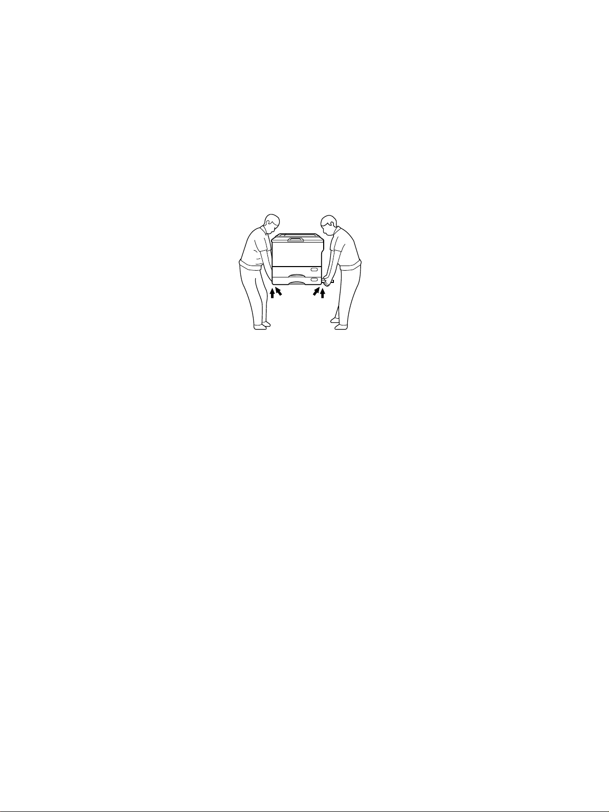
1. Transportation/Installation
• When transporting/installing the copier, employ two persons and be sure to use the positions as
indicated below.
The copier is fairly heavy and weighs approximately 83 kg (183 lb), therefore pay full attention
when handling it.
4 portions
2. Installation
• Be sure to use a dedicated outlet with AC 115V/15A (220V, 240V/10A) or more for its power
source.
• The copier must be grounded for safety.
Never ground it to a gas pipe or a water pipe.
• Select a suitable place for installation.
Avoid excessive heat, high humidity, dust, vibration and direct sunlight.
• Also provide proper ventilation as the copier emits a slight amount of ozone.
• To insure adequate working space for the copying operation, keep a minimum clearance of 80 cm
(32”) on the left, 80 cm (32”) on the right and 10 cm (4”) in the rear.
• Secure the lifting handles with the fixing plates and screws after the installation is finished.
3. Service of Machines
• Basically, be sure to turn the main switch off and unplug the power cord during service.
• Be sure not to touch high-temperature sections such as the exposure lamp, the fuser unit, the
damp heater and their periphery.
• Be sure not to touch high-voltage sections such as the chargers and the high-voltage transformer.
• Be sure not to touch rotating/operating sections such as gears, belts, pulleys, etc.
• When servicing the machines with the main switch turned on, be sure not to touch live sections
and rotating/operating sections. Avoid exposure to laser radiation.
• Use suitable measuring instruments and tools.
Page 3

4. Main Service Parts for Safety
• The breaker, door switch, fuse, thermostat, thermofuse, thermistor, etc. are particularly important
for safety. Be sure to handle/install them properly.
5. Cautionary Labels
• During servicing, be sure to check the rating plate and the cautionary labels such as “Unplug the
power cord during service”, “Hot area”, “Laser warning label” etc. to see if there is any dirt on their
surface or whether they are properly stuck to the copier.
6. Disposition of Consumable Parts/Packing Materials
• Regarding the recovery and disposal of the copier, supplies, consumable parts and packing materials, it is recommended to follow the relevant local regulations or rules.
7. When parts are disassembled, reassembly is basically the reverse of disassembly unless
otherwise noted in this manual or other related documents. Be careful not to reassemble
small parts such as screws, washers, pins, E-rings, toothed washers in the wrong places.
8. Basically, the machine should not be operated with any parts removed or disassembled.
9. Precautions Against Static Electricity
• The PC board must be stored in an anti-electrostatic bag and handled carefully using a wristband,
because the ICs on it may become damaged due to static electricity.
Caution: Be sure to turn off the copier before attaching the wrist-band.
Always remove the wrist-band before applying power.
Page 4

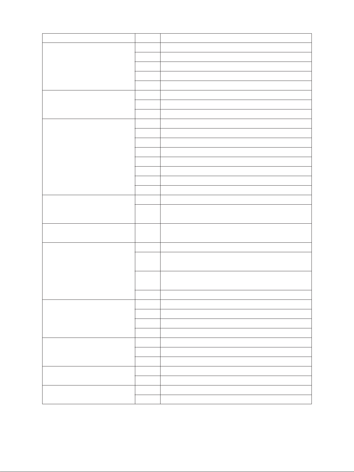
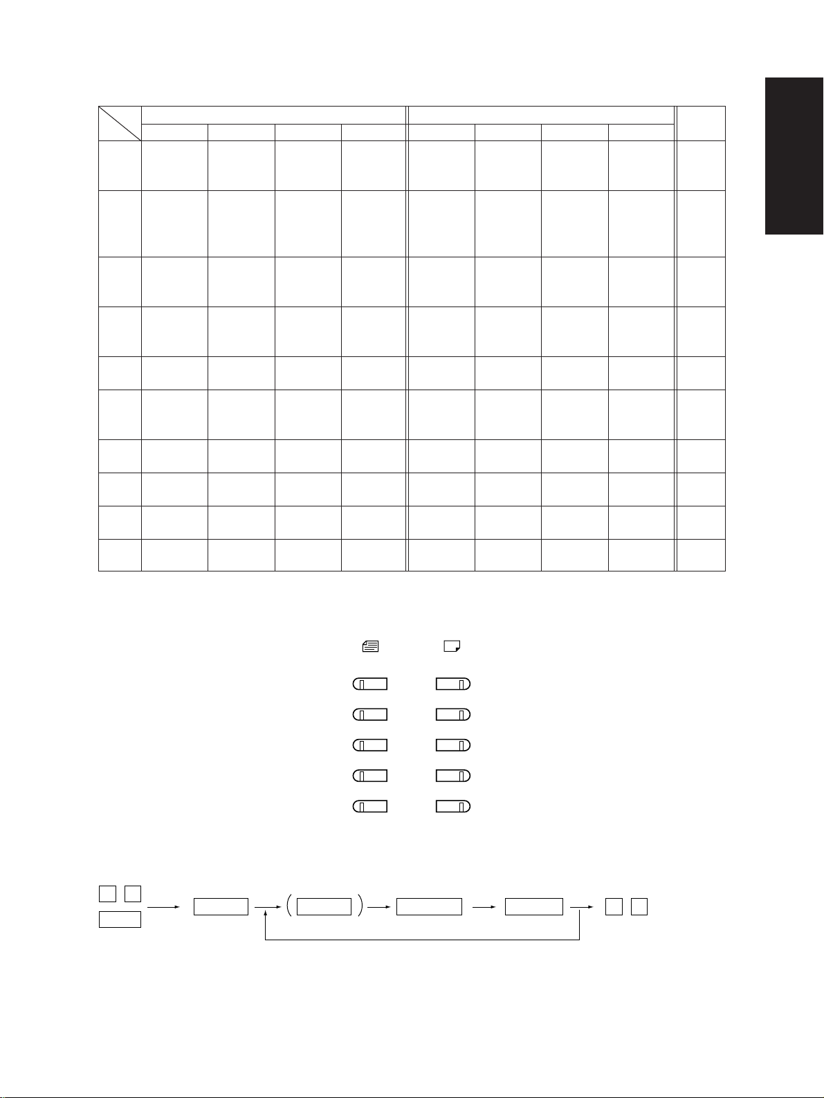
1. ADJUSTMENT ITEMS
1.1 Error Codes
When either the CLEAR PAPER ( ) or CALL SERVICE ( ) symbol appears, press the CLEAR/
STOP and “8” keys simultaneously and the corresponding error code will be displayed. To clear the
error code, turn off the machine.
Group
Transporting jam inside the copier
Paper feeding jam
Paper transporting jam
Paper jam if some cover is
opened during copying
Original transporting jam at the
ADF
Error code
E01
E02
E03
E04
E05
E08
E09
E11
E12
E13
E14
E15
E16
E17
E19
E21
E22
E23
E24
E25
E41
E42
E43
E44
E45
E46
E71
E72
E73
E79
Machine status
Paper jam inside the copier
Paper jam near the fuser unit
Paper remaining inside the machine at power on
The front cover is opened during copying
Paper jam near the aligning roller
Paper jam at the stacking area inside the ADU
Code error/system board
Paper feeding jam at the ADU
Manual feeding jam
1st cassette (Upper cassette) feeding jam
2nd cassette (Lower cassette) feeding jam
3rd cassette (PFP upper cassette) feeding jam
4th cassette (PFP middle cassette) feeding jam
5th cassette (PFP lower cassette) feeding jam
LCF feeding jam
Paper jam at the LCF
Paper jam inside the copier
Paper jam near the aligning roller
PFP emergency stop
Paper jam at the PFP
Copier front cover is opened during copying
PFP side door is opened during copying
ADU is withdrawn during copying
Copier side door is opened during copying
LCF unit is opened during copying
Manual feed unit is opened during copying
Original feeding jam at the feeding area of the ADF
Original transporting jam at the transporting area of the ADF
Original exiting jam at the exiting area of the ADF
Original prefeeding jam
September 1997 © TOSHIBA CORP. 1 - 1 2460 ADJUSTMENT
Page 5
Group
Paper jam at the finisher
CALL SERVICE from the drive
system
CALL SERVICE from the paper
feeding system
CALL SERVICE from the optical
system
CALL SERVICE from the process
system
Fuser unit area
CALL SERVICE from communication
CALL SERVICE from ADF
CALL SERVICE from others
CALL SERVICE from the laser
optical system
Error code
EA1
EA2
EA4
EA5
EA6
C01
C04
C05
C1 1
C12
C13
C14
C15
C16
C17
C18
C21
C26
C33
C41
C43
C44
C45
C55
C56
C57
C58
C72
C73
C74
C94
C99
CA1
CA2
Machine status
Transporting delay jam
Transporting stationary jam
Door open jam
Staple jam
Early arrival jam
Copier main motor operation abnormal
PFP main motor operation abnormal
ADU main motor operation abnormal
ADU side motor operation abnormal
ADU end motor operation abnormal
Copier upper cassette tray operation abnormal
Copier lower cassette tray operation abnormal
PFP upper cassette tray operation abnormal
PFP middle cassette tray operation abnormal
PFP lower cassette tray operation abnormal
LCF tray operation abnormal
Carriage initialization error
Exposure lamp disconnection detected or exposure peak
detection error
Easy setup has failed
Abnormal thermistor or heater disconnection when power is on
Warming up mode after disconnection judgement, or abnormal thermistor after ready
Warming up mode after disconnection judgement, or heater
disconnection after ready
Heater end thermistor disconnection
Communication error between ADF and MCPU
Communication error between PFC and MCPU
Communication error between MCPU and IPC
Communication error between IPC and the finisher
Poor adjustment by the aligning sensor detected
EEPROM poor initialization
Poor adjustment by the exit/reverse sensor detected
MCPU is abnormal
PFC microcomputer is abnormal
Polygonal motor is abnormal
HSYNC is abnormal
2460 ADJUSTMENT 1 - 2 September 1997 © TOSHIBA CORP.
Page 6

Group
CALL SERVICE from the finisher
CALL SERVICE from optional
units
Error history(08-253)
(Display example) EA1 970826175732 6 4 6 4 236210000000
Error code YYMMDDHHMMSS MMM NNN ABCDEFGHIJKL
3
digit 12digit(Date,time) 3digit 3digit 12digit(Copy mode)
Copy mode
A Paper feed cassette
0 : Non-select 1 : SFB 2 : LCF 3 : PFP(U) 4 : PFP(M) 5 : PFP(L) 6 : ADU 7 : Copier(U)
8 : Copier (L)
B Paper size code
0 : A5 1 : A5-R 2 : ST-R 3 : LT 4 : A4 5 : B5-R 6 : LT-R 7 : A4-R 8 : OTHER/UNIV 9 : B5
A : FOL/COM B : LG C : B4 D : LD E : A3
C Sort mode
0 : Non-select 1 : Group 2 : Sort 6 : Staple Sort
D DF mode
0 : Not used 1 : AUTO FEED(SADF) 2 : STACK FEED
E APS/AMS mode
0 : Non-select 1 : APS 2 : AMS
F Deplex mode
0 : Non-select 1 : Book 2 : Dual-sided/One-sided 4 : Dual-sided/Dual-sided 8 : One-sided/Dual-sided
G Not used
0 : Not used
H Image shift
0 : Not used 1 : Book 2 : LEFT 4 : RIGHT
I Editing
0 : Not used 1 : Masking 2 : Triming
J Edge-erase/Dual-page
0 : Not used 1 : Edge-erase 2 : Dual-page 3 : Edge-erase&Dual page
K Not used
0 : Not used
L Function
0 : Standard PPC 1 : Extended PPC 2 : FAX Tx 3 : FAX Rx 4 : GDI 5 : DSS
MMM Primary scanning reproduction ratio(Y direction)
Hexadecimal
NNN Secondary scanning reproduction ratio(X direction)
Hexadecimal
Setting mode, code "253" displays latest 8 error data
Error code
CB1
CB2
CB3
CB4
CB5
CB6
CB7
F10
Machine status
Feed motor of the finisher is abnormal
Delivery motor of the finisher is abnormal
Elevation motor of the finisher is abnormal
Alignment motor of the finisher is abnormal
Staple motor of the finisher is abnormal
Staple shift motor of the finisher is abnormal
Distance sensor of the finisher is abnormal
HDD initialization error
(Reproduction ratio)
September 1997 © TOSHIBA CORP. 1 - 3 2460 ADJUSTMENT
Page 7
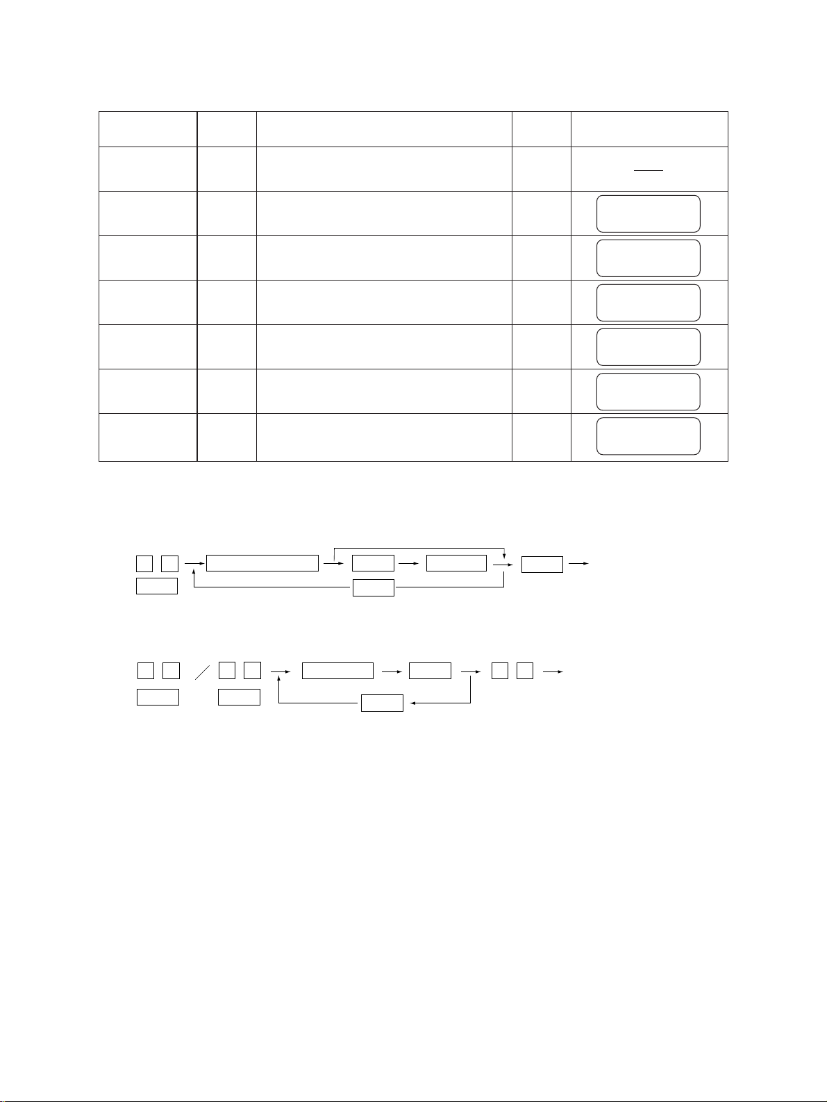
1.2 Self-Diagnosis Modes
Mode
All-LEDs-lit
Aging mode
Test mode
Test print
mode
Adjustment
mode
Aging mode
Setting mode
Input
code method
“01”
“02”
“03”
“04”
“05”
“07”
“08”
All LEDs on the control panel are lit.
Aging (RADF does not operate)
Motor test and input/output check
Test print
Adjustment of items
Aging (includes RADF)
System switchover and setting of each
Definition
priority mode, PM counter, etc.
Cleaning
C/S
“09”
“09”
“09”
“09”
“09”
“09”
Display after selection
AGING MODE
100%
TEST MODE
100%
TEST PRINT MODE
100%
TEST MODE
100%
AGING MODE 2
100%
TEST MODE
100%
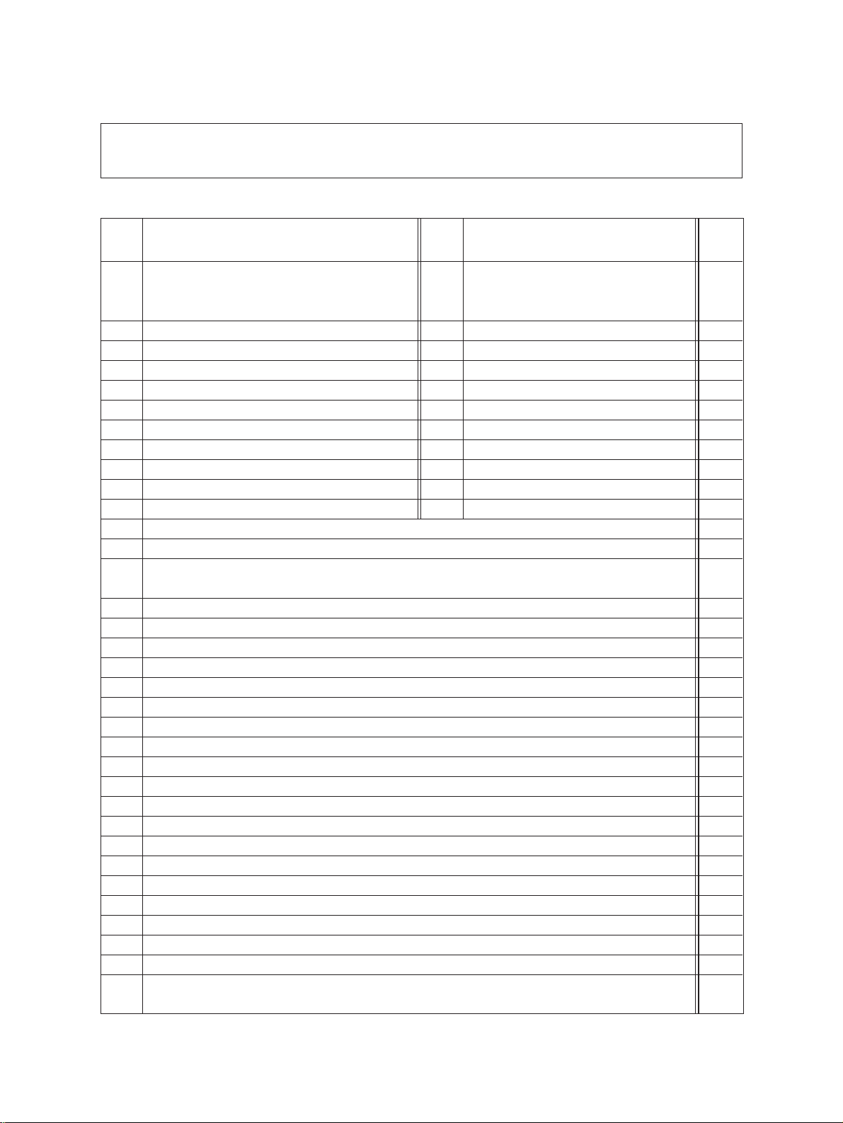
Note: To access the desired diagnostic mode, turn on the power switch while pressing the appropriate keys.
<Procedure>
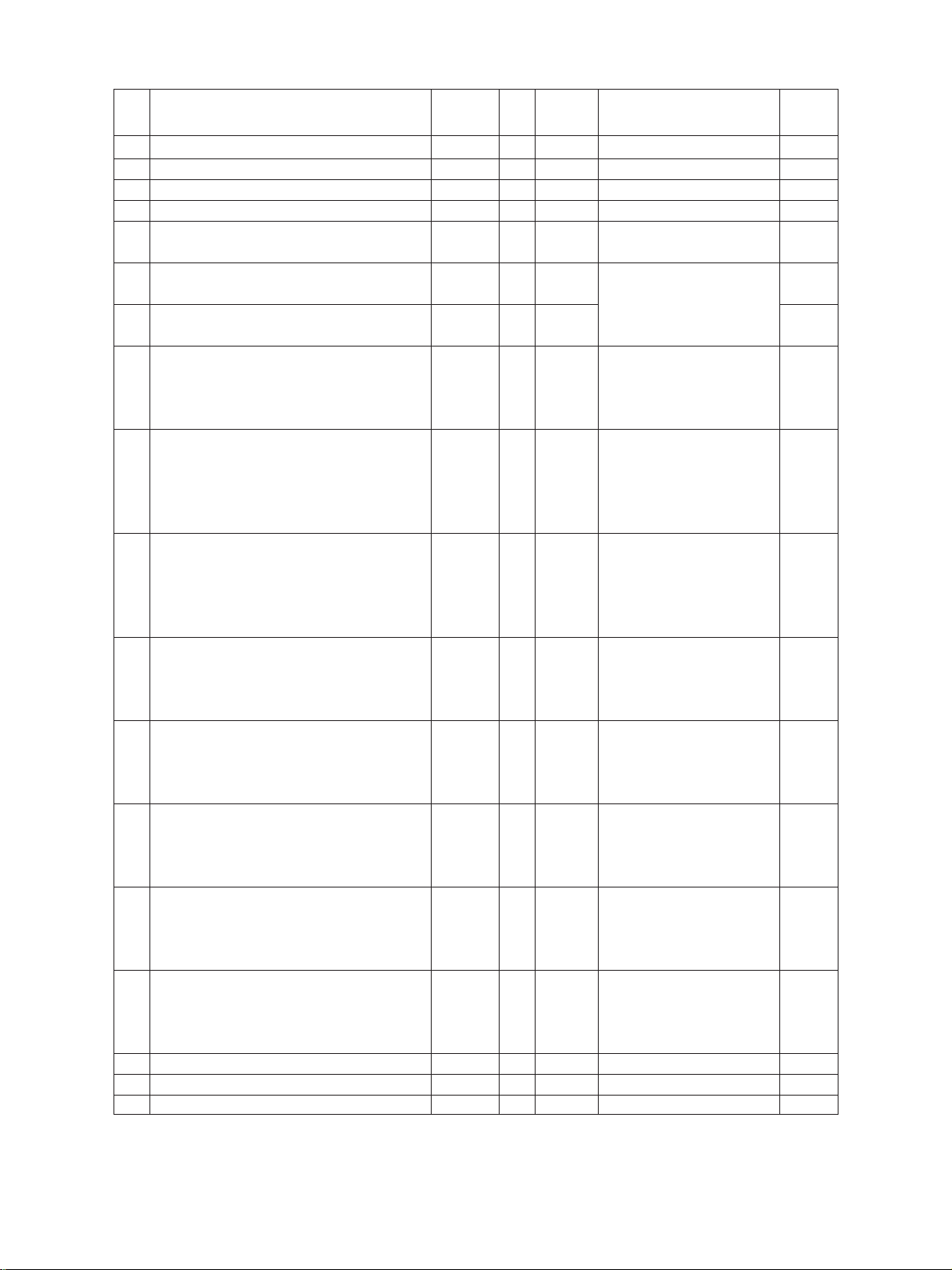
•All-LEDs-lit mode (01):
0 1
PWR
All LEDs light
START
START
Key check
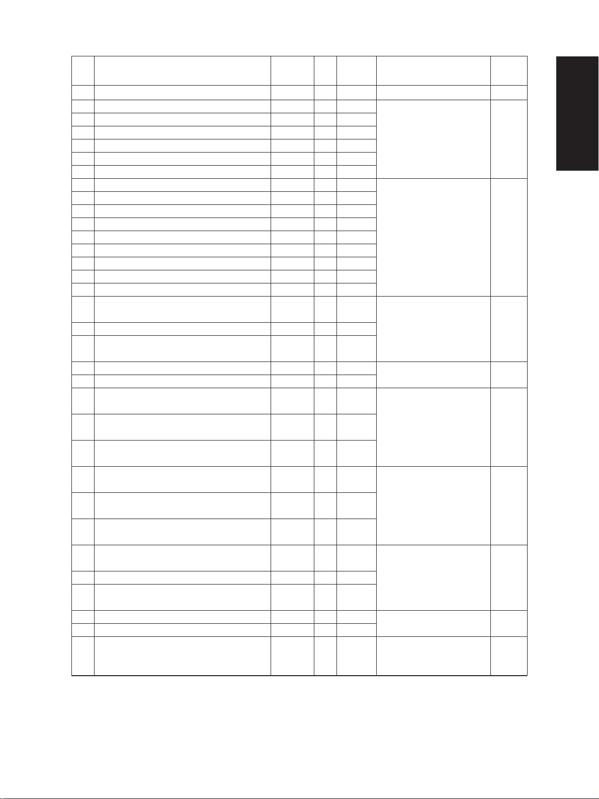
•Aging mode (02 or 07):
0 2 0 9
PWR
0 7
PWR
Aging
C/S
START
•Test mode (03): Refer to 1.2.1 and 1.2.2.
•Test print mode (04): Refer to “1.2.3 Test print mode”.
•Adjustment mode (05): Refer to “1.2.4 Adjustment mode”.
•Setting mode (08): Refer to “1.2.5 Setting mode”.
Notes: C/S: Press the CLEAR/STOP key
PWR: Turn on the power switch
INT: Press the INTERRUPT key
E/S: Press the ENERGY SAVER key
C/S
Exit
Exit
2460 ADJUSTMENT 1 - 4 September 1997 © TOSHIBA CORP.
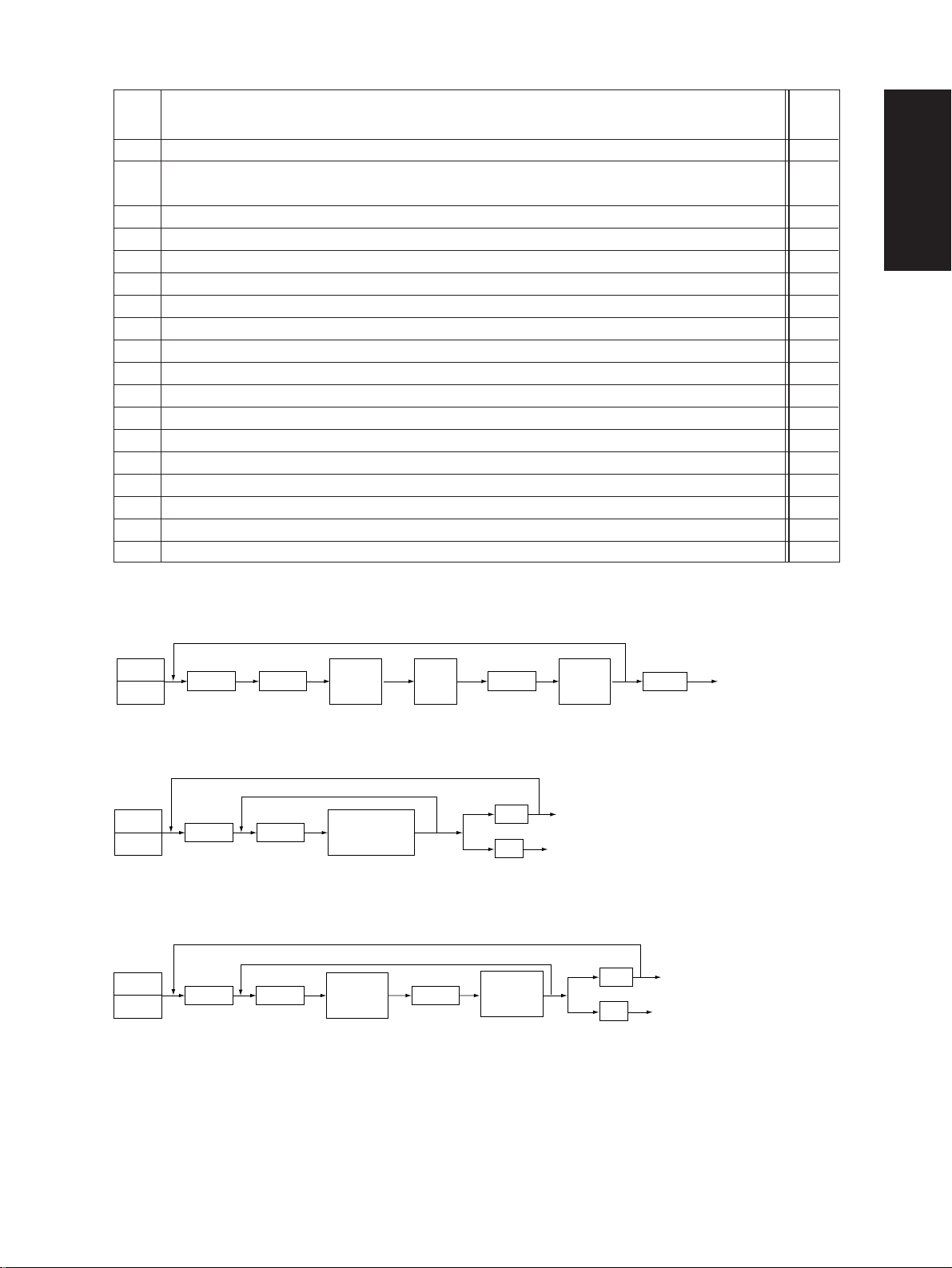
Page 8

Warming up
Normal
“C”
“01”
*2
All the displays on
the control panel lit
Power ON
“02”
“07”
(With ADF)
Aging
“03”
Test mode
“05” “08”
Adjustment mode
Setting mode
“04”
Test print mode
Standby
“S” “C”
Stops momentarily
“09”
*1
“09” “09”
“S”: START key on.
“C”: CLEAR/STOP key on.
“05”
“09”
“09”
Quick reference chart for self-diagnostic mode
*1 When the copier is in the adjustment mode which you entered by turning on the power switch while
pressing keys “0” and “5” simultaneously, pressing keys “0” and “9” simultaneously will make the
copier exit into the standby mode. In this standby mode only , can the adjustment mode be accessed
repeatedly by simply entering “0” and “5”.
*2 While all the displays on the control panel are lit (“01” mode), copying is disenabled.
When the copier enters the standby status by the pressing of the CLEAR/STOP key, copying is
enabled.
September 1997 © TOSHIBA CORP. 1 - 5 2460 ADJUSTMENT
Page 9
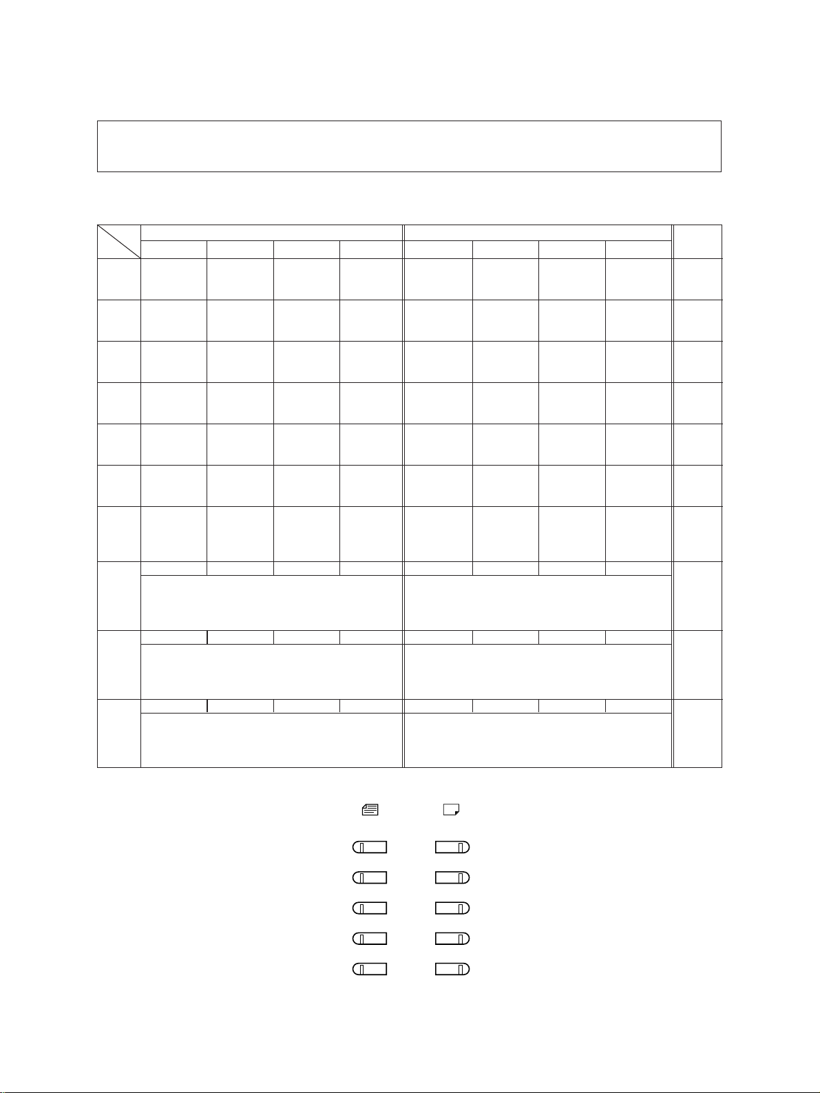
1.2.1 Input signal check (Test mode 03)
In the “03” test mode, the following input signal conditions can be checked by pressing the appropriate
keys.
[A]
When the ENERGY SAVER key is OFF status (LED indicating the energy saver mode is out)
LED
Key
[1] Key
[2] Key
[3] Key
[4] Key
[5] Key
[6] Key
[7] Key
[8] Key
[9] Key
[0] Key
Original size LED Copy size LED
A4/LD A3/LG B4/LT A5/ST A4/LD A3/LG B4/LT A5/ST
Front cover
–
–
–
–
–
open
–
HTRDY-0
Heater lamp
OFF
–
–
PRTM-1
Platen cover
closed
–
–
–
SIZCU-3
SYZPF1-3
SYZPF3-3
–
SCNCNT-0
Scanner
–
unconnected
PSTP-1
–
Paper stop sensor
paper supplied
–
APS3
APS sensor
input 3
APS2
APS sensor
input 2
Size width
sensor 2
SIZCU-2
SIZCU-1
Copier upper size SW
SYZPF1-2
SYZPF1-1
PFP upper size SW
SYZPF3-2
SYZPF3-1
–
–
–
–
TFUL-0
Toner-full
SW OFF
–
–
APS1
APS sensor
input 1
Size width
sensor
SIZCU-0
SYZPF1-0
SYZPF3-0
CLEAR
Coin vender
clear
PFACK
PFC ACK
DFACK
ACK signal
from ADF
HSYNC-1
HSYNC error
–
Empty
sensor
SIZCL-3
SYZPF2-3
SSIZE-3
–
EXITSW-0
Paper exit SW
detected paper
FNCNT-0
Finisher
unconnected
PMTLK-0
POL-MOT
abnormal rotation
ADCNT-0
ADF
unconnected
MMPLL
MAIN-MOT
–
abnormal rotation
APSR
APS sensor
input R
Door sensor
open
SIZCL-2
APSC
APS sensor
input C
Exit/Reverse
sensor
SIZCL-1
Copier lower size SW
SYZPF2-2
SYZPF2-1
PFP middle size SW
SSIZE-2
SSIZE-1
–
CTRIN-0
Key counter
unconnected
PSTPR
Paper feeding
status signal
DEVCNT-0
Dev unit
unconnected
HOME-1
Carriage
home
Aligning
sensor
SIZCL-0
SYZPF2-0
SSIZE-0
Bypass width size SWPFP lower size SW
–
Remarks
MCPU
PD
C2XB
IN2
C2XB
IN0
MCPU
PE
MCPU
P8
MCPU IN1
Lighting/
No paper
ADF
→ MCPU
Lighting/
Paper
PFC
→ MCPU
Paper size
Lighting/
SW off
PFC
→ MCPU
Paper size
Lighting/
SW off
PFC
→ MCPU
Paper size
Lighting/
SW off
LED lit in above condition (Signal level : H)
ORIGINAL COPY
A4/LD
A3/LG
B4/LT
A5/ST
UNIVERSAL/
OTHER
2460 ADJUSTMENT 1 - 6 September 1997 © TOSHIBA CORP.
Page 10
[B] When the ENERGY SAVER key is ON status (LED indicating the energy saver mode is lit)
LED
Key
[1] Key
[2] Key
[3] Key
[4] Key
[5] Key
[6] Key
[7] Key
[8] Key
[9] Key
[0] Key
A4/LD A3/LG B4/LT A5/ST A4/LD A3/LG B4/LT A5/ST
–
SBFSW
Manual feed
SW detected
no paper
–
–
–
–
–
HTRTH-7
DRMTH-7
HTRDY2-7
Original size LED Copy size LED
TUPCL
Copier lower
tray lifted up
SCOVDOR
Manual feed
door open
TUPPF2
PFP middle
tray lifted up
PPLL-OK
PFP motor
abnormal rotation
AD-CNT
ADU
unconnected
HTRTH-6
DRMTH-6
HTRDY2-6
PEMPCL
Copier lower
paper empty
LC-KEY
LCF tray
down key
OFF
PEMPPF2
PFP middle
paper empty
PF-CNT
PFP
unconnected
–
APLL-OK
ADU motor
abnormal rotation
–
HTRTH-5
DRMTH-5
HTRDY2-5
PSTPCL
Copier lower
paper stopped
LC-CNT
LCF
unconnected
PSTPPF2
PFP middle
paper stopped
PFDOR
PFP side
door opened
–
SIDSW
ADU side
SW ON
–
HTRTH-4
DRMTH-4
HTRDY2-4
LED lit in above condition (Signal level : H)
–
–
UCVDOR
Copier side
door opened
LCDOR
LCF door
open
–
–
–
ENDSW
ADU end
SW ON
–
HTRTH-3
DRMTH-3
HTRDY2-3
TUPCU
Copier upper
tray lifted up
TDWNLC
LCF tray
lifted down
TUPPF1
PFP upper
tray lifted up
TUPPF3
PFP lower
tray lifted up
–
PJAM1AD
ADU
Jam SW ON
–
HTRTH-2
DRMTH-2
HTRDY2-2
–
–
–
PSTPCU
Copier upper
paper stopped
PEMPLC
LCF paper
empty
PSTPPF1
PFP upper
paper stopped
PSTPPF3
PFP lower
paper stopped
–
PEMPAD
Paper in
ADU
–
HTRTH-0
DRMTH-0
HTRDY2-0
PEMPCU
Copier upper
paper empty
TUPLC
LCF tray
lifted up
PEMPPF1
PFP upper
paper empty
PEMPPF3
PFP lower
paper empty
HTRTH-1
DRMTH-1
HTRDY2-1
1: Fuser thermistor condition
*
2: Drum thermistor condition
*
3: Fuser thermistor-2 condition
*
Remarks
PFC →
MCPU A
PFC →
MCPU B
PFC →
MCPU C
PFC →
MCPU D
–
PFC →
MCPU
ADU
–
MCPU
1
PC*
MCPU
2
PC*
MCPU
3
PC*
ORIGINAL COPY
A4/LD
A3/LG
B4/LT
A5/ST
UNIVERSAL/
OTHER
<Procedure>
0 3
START
ENERGY SAVER
Digital keys
LED ON
PWR
Note: 03 → With initialization before test mode is entered
September 1997 © TOSHIBA CORP. 1 - 7 2460 ADJUSTMENT
0 9
(To clear)
Page 11
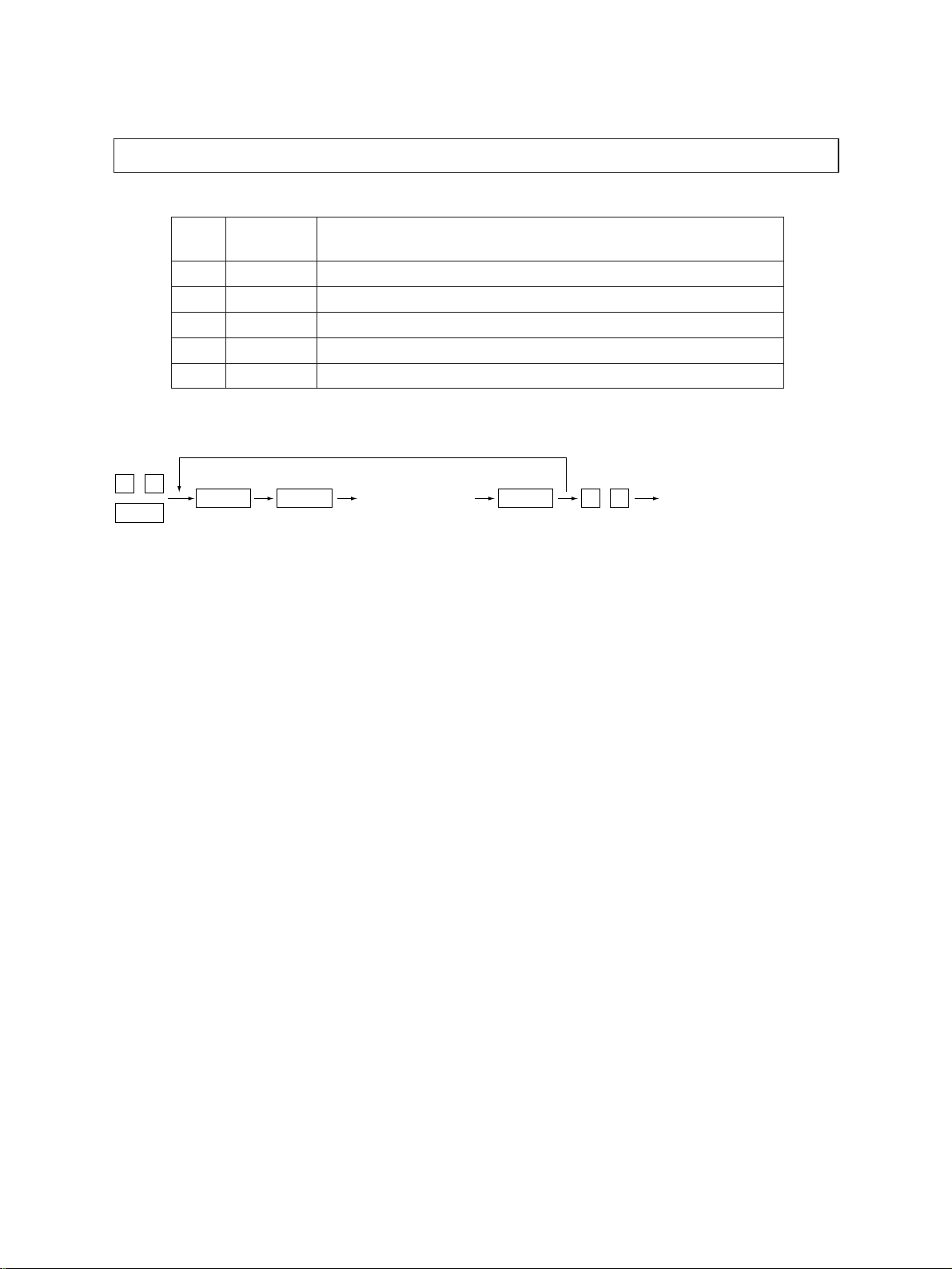
1.2.2 Output signal check (03)
In the “03” test mode, the following output signal conditions can be checked by entering appropriate
codes.
Operation
Code Function Code Function
101 Main motor ON*
(Transfer, Separation and Discharge chargers, and
also PCC are ON)
102 Toner motor ON 152 OFF 1
103 Polygonal motor (600 dpi) ON 153 OFF 1
104 Polygonal motor (400 dpi) ON 154 OFF 1
105 Polygonal motor (16 x 15.4) ON 155 OFF 1
106 Polygonal motor (15.4 x 16) ON 156 OFF 1
107 Polygonal motor (at standby) ON 157 OFF 1
108 Copier aligning clutch ON 158 OFF 1
109 PFP main motor ON 159 OFF 1
110 ADU main motor ON 160 OFF 1
111 Scraper solenoid ON 161 OFF
201 Copier upper cassette feed clutch ON/OFF 3
202 Copier lower cassette feed clutch ON/OFF 3
203 Intermediate transporting clutch ON/OFF 3
(PFP transporting clutch)
204 Manual feed clutch ON/OFF 3
222 ADU feed clutch ON/OFF 3
223 ADU stack clutch ON/OFF 3
225 PFP transporting clutch ON/OFF 3
226 PFP upper cassette feed clutch ON/OFF 3
227 PFP middle cassette feed clutch ON/OFF 3
228 PFP lower cassette feed clutch ON/OFF 3
241 Total counter count-up (count-up only) 2
242 Copier upper cassette tray motor lift UP 2
243 Copier lower cassette tray motor lift UP 2
250 Developer bias transformer ON/OFF 3
251 Main charger transformer ON/OFF 3
252 Transfer charger transformer ON/OFF 3
253 Separation charger transformer ON/OFF 3
254 PCC transformer ON/OFF 3
255 Transfer guide bias ON/OFF 3
256 Laser ON/OFF 3
257 Exit fan motor ON/OFF 3
258 Duct fan motor 1 ON/OFF 3
261 Scanning motor ON 2
(automatically stops at the limit position, its speed is variable using the ZOOM keys)
1: Functional when the developer unit is not installed.
*
1
151 OFF 1
2460 ADJUSTMENT 1 - 8 September 1997 © TOSHIBA CORP.
procedure
group
Page 12
Operation
Code Function
262 Document (indicator) motor ON 2
263 Halogen lamp ON 3
(automatically goes off after 6 seconds, and the fan motors rotate at low speed)
264 Optical fan motor F ON/OFF 3
265 Optical fan motor R ON/OFF 3
270 LCF feed motor ON/OFF 2
271 LCF tray motor lift UP/DOWN 2
272 ADU side motor ON/OFF 3
273 ADU end motor ON (Come/Go) 2
274 ADU stack solenoid ON/OFF 3
275 PFP upper cassette tray motor lift UP 2
276 PFP middle cassette tray motor lift UP 2
277 PFP lower cassette tray motor lift UP 2
281 ADF pick-up roller rotation ON/OFF 3
282 ADF aligning roller rotation ON/OFF 3
283 ADF transport belt CW rotation ON/OFF 3
284 ADF transport belt CCW rotation ON/OFF 3
401 Memory size of the PM board is checked 2
402 Reading/Writing operation of the PM board is checked 2
procedure
group
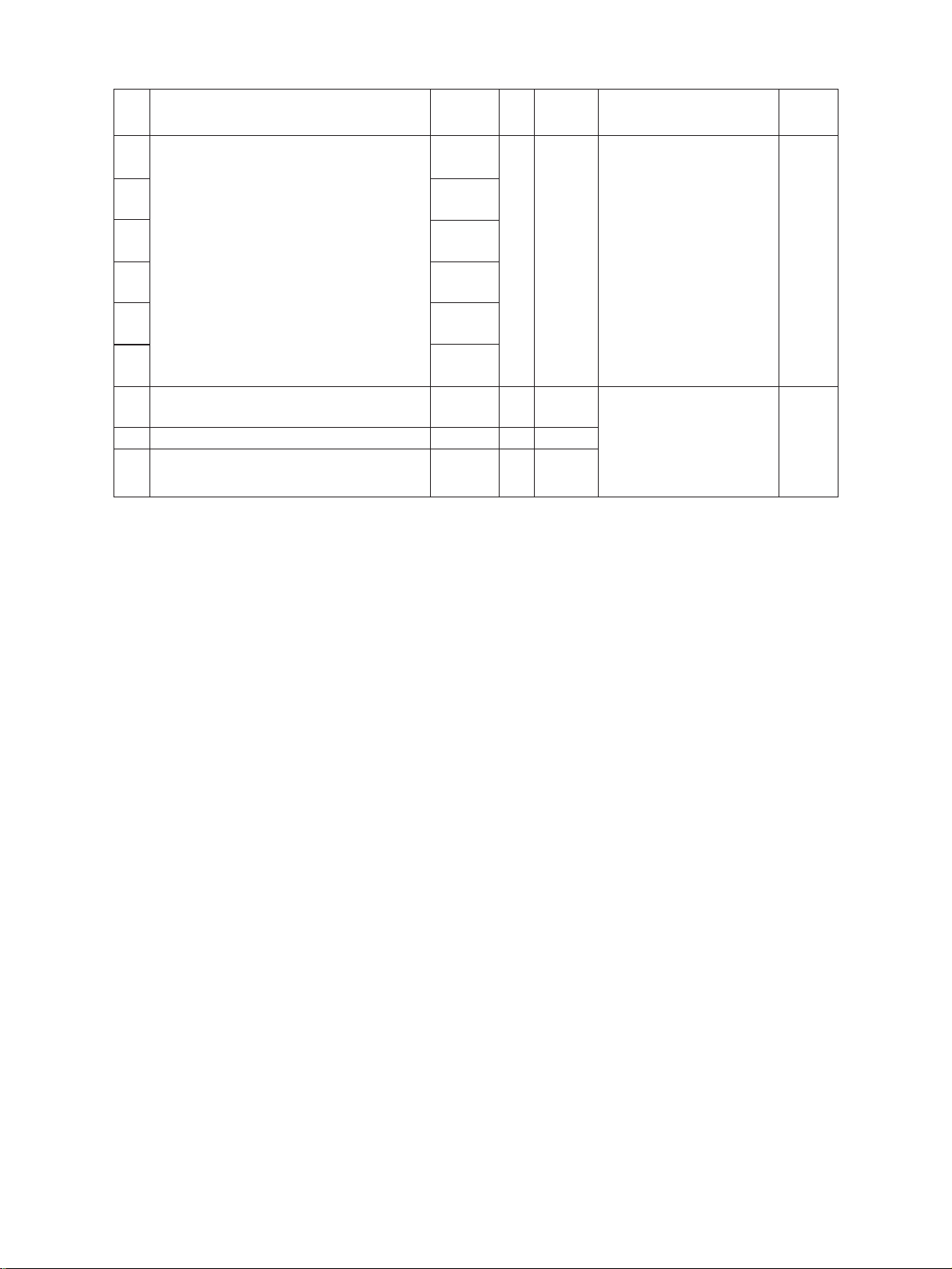
<Operation procedure group>
Group (1)
03
PWR
Code
START
Group (2)
03
PWR
Code
START
Group (3)
03
PWR
Code
START
Operation
(ON)
Operation
(ON)
Operation
(ON)
Stop
code
START
START
C/S
09
Operation
(OFF)
Operation
(OFF)
09
Test mode standby
Warm-up
C/S
09
Warm-up
Test mode standby
Warm-up
September 1997 © TOSHIBA CORP. 1 - 9 2460 ADJUSTMENT
Page 13
1.2.3 Test Print (Test Mode “04”)
In test mode “04,” you can print the test pattern generated by the following ASIC codes.
Code ASIC Test Pattern type
111 SARAH Primary scanning, 33 gradation (2nd step), error diffusion
113 SARAH Secondary scanning, 33 gradation (2nd step), error diffusion
142 HPS 2-dot grid pattern (Pitch 10 mm)
183 SARAH Primary scanning, 33 gradation (2nd step), + dither process, for fax
184 SARAH Secondary scanning, 33 gradation (2nd step), + dither process, for fax
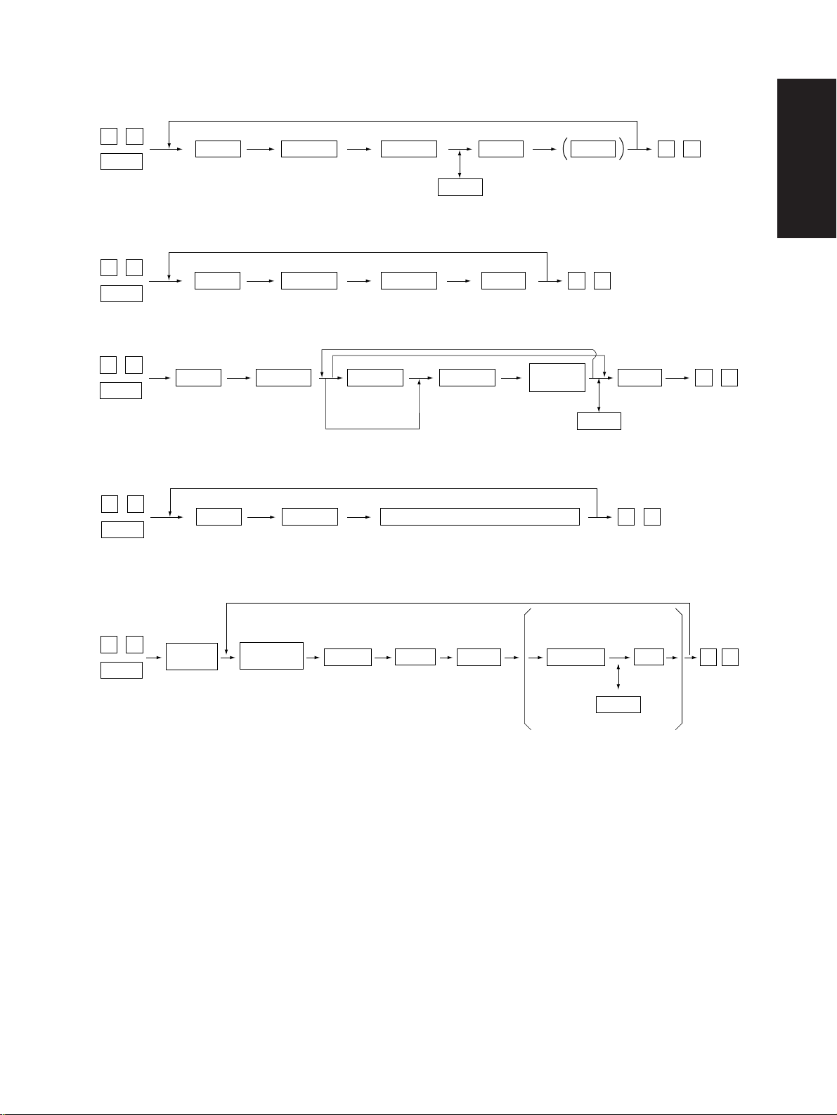
<Operation procedure>
0 4
PWR
Note: Though errors are displayed when generated, recovery is not carried out. This is remedied by turning the
Code
power OFF then ON again.
START
Operation
(Test print)
C/S
0 9
Warming up
2460 ADJUSTMENT 1 - 10 September 1997 © TOSHIBA CORP.
Page 14

1.2.4 Adjustment mode (05)
In this mode, the following adjustment items can be corrected or changed. T o access this code, turn on
the power while pressing the “0” and “5” keys.
Code Adjustment Mode
200 Auto-toner automatic adjustment ALL – – • Increasing the value increases
201 Auto-toner manual adjustment ALL 128 0~255 The auto toner sensor adjust- 2
205 Developer bias, DC adjustment ALL 174 0~255 The transformer output is aug- 2
210 Grid voltage initial value adjustment ALL 114 0~255 mented by increasing the value
220 Transfer, DC output, High, adjustment ALL 125 0~255 by “1”.
221 Transfer, DC output, Center, adjustment ALL 75 0~255
222 Transfer, DC output, Low, adjustment ALL 75 0~255
230 Separation, AC output, High, adjustment ALL 156 0~255
231 Separation, AC output, Center, adjustment ALL 156 0~255
232 Separation, AC output, Low, adjustment ALL 62 0~255
240 Pre-Cleaning Discharge, AC output adjustment ALL 142 0~255 (Note 2)
261 Laser power, 600 dpi, initial value adjustment ALL 58 0~255 2
304 Scanner secondary scanning reproduction ratio
305 Scanner secondary scanning deviation ALL 135 85~171 If the value is increased by “1”, 1
306 CCD primary scanning deviation ALL 85 5~251 If the value is increased by “1”, 1
310 Halogen lamp light on voltage setting ALL 55 50~70 3
313 Original leading edge image deletion
314 Original leading edge image deletion
Standard PPC
Standard PPC
Extended PPC
Initial
Allowance Contents
value
the sensor output.
•The output is set in the range
of 2.35~2.45V automatically
after changing the value and
2 minutes after starting this
mode. (Note 1)
ment value can be displayed.
128 0~255 If the value is increased by “1”, 1
the reproduction ratio of the
paper feeding direction is enlarged by approx. 0.1522%.
the image shifts approx. 0.1213
mm to the trailing edge of the
paper.
the image shifts approx. 0.0423
mm to the front side.
128 128~255 If the value is increased by “1”, 1
the leading edge void is enlarged
by approx. 0.1213 mm for a
standard copy.
128 128~255 If the value is increased by “1”, 1
the leading edge deletion is enlarged by approx. 0.1213 mm
for a special function copy.
Operation
procedure
group
(Note 1): Refer to 1.3.
(Note 2): Functional with the developer unit removed and the service jig attached. However, the jig is not necessary for the devel-
oper bias adjustment. Refer to 1.9.
September 1997 © TOSHIBA CORP. 1 - 11 2460 ADJUSTMENT
Page 15
Code Adjustment Mode
315 Original leading edge void adjustment ALL 0 0~255 0.04233mm/count 1
340 Reserved
350 ADF single-sided original stop position ALL 8 0~15 1
351 ADF two-sided original stop position ALL 8 0~15 1
356 ADF EEPROM initialization, ADF sensor ALL – – 4
automatic adjustment
400 Polygonal motor rotation, fine adjustment, 600dpi
401 Polygonal motor rotation, fine adjustment, 600dpi GDI 128 114~142
405 Polygonal motor rotation, fine adjustment, 600dpi
410 Laser starting position, 600dpi PPC 80 0~255 If the value is increased by “1”, 5
412 Laser starting position, 400dpi GDI 96 0~255 If the value is increased by “1”, 5
421 Secondary scanning reproduction ratio, main PPC 140 1~255 If the value is increased by “1”, 5
motor speed, fine adjustment the reproduction ratio of the
430 Top margin
431 Left margin
432 Right margin
433 Bottom margin
435 Reserved
436 Reserved
437 Reserved
Standard PPC
Extended PPC
Standard PPC
Standard PPC
Standard PPC
Standard PPC
Initial
Allowance Contents
value
128 114~142 If the value is increased by “1“, 1
the primary scanning reproduction ratio is enlarged by approx
0.225%.
128 114~142 If the value is increased by “1“, 1
the primary scanning reproduction ratio is increased by approx.
0.225%.
the effective image data writing
area on the drum is shifted by
0.0423 mm to the primary scan-
ning direction.
the effective image data writing
area on the drum is shifted by
0.0635 mm to the primary scan-
ning direction.
paper feeding direction is enlarged by approx. 0.0315%.
0 0~255 If the value is increased by “1”, 1
the white area of the leading
edge is increased by approx.
0.04233 mm.
0 0~255 If the value is increased by “1”, 1
the white area of the left edge
is increased by approx.
0.04233 mm.
0 –94~255 If the value is increased by “1”, 1
the white area of the right edge
is increased by approx.
0.04233 mm.
0 –94~255 If the value is increased by “1”, 1
the white area of the trailing
edge is increased by approx.
0.04233 mm.
Operation
procedure
.5
group
2460 ADJUSTMENT 1 - 12 September 1997 © TOSHIBA CORP.
Page 16
Code Adjustment Mode
438 Reserved
440 Registration, Copier upper cassette ALL 8 0~15 If the value is increased by “1”, 5
441 Registration, Copier lower cassette ALL 13 0~40 the registration position of the
442 Registration, Bypass ALL 8 0~15 image is shifted by approx. 0.5
443 Registration, LCF ALL 8 0~15 mm to the paper leading edge.
444 Registration, PFP ALL 8 0~15
445 Registration, ADU ALL 8 0~15
450 Aligning value, Copier upper cassette, long size ALL 14 0~31 Increasing the value by “1” en- 1
451 Aligning value, Copier upper cassette, short size ALL 16 0~31 larges the aligning by 0.8 mm.
452 Aligning value, Copier lower cassette, long size ALL 14 0~31
453 Aligning value, Copier lower cassette, short size ALL 16 0~31
454 Aligning value, ADU, long size ALL 14 0~31
455 Aligning value, ADU, short size ALL 16 0~31
456 Aligning value, PFP ALL 14 0~31
457 Aligning value, LCF ALL 14 0~31
458 Aligning value, BYPASS ALL 22 0~31
500 Manual exposure, fine adjustment, Center value Standard 128 0~255 If the value is increased, the 1
PPC (Photo/Text)
501 Manual exposure, fine adjustment, Center value
502 Manual exposure, fine adjustment, Center value Standard 128 0~255
503 Reserved
504 Reserved
505 Manual exposure fine adjustment, PPC 23 0~255 If the value is increased, the 1
Light side step value
506 Manual exposure fine adjustment, PPC 20 0~255 the light side of the exposure
Light side step value (Photo) indicator.
507 Manual exposure fine adjustment, PPC 25 0~255
Light side step value (Text)
508 Manual exposure fine adjustment, PPC 18 0~255 If the value is increased, the 1
Dark side step value
509 Manual exposure fine adjustment, PPC 20 0~255 the dark side of the exposure
Dark side step value (Photo) indicator.
510 Manual exposure fine adjustment, PPC 20 0~255
Dark side step value (Text)
511 Automatic exposure fine adjustment
512 Automatic exposure fine adjustment
513 Automatic exposure fine adjustment Standard 128 0~255
514 Reserved
515 Reserved
580
Automatic gamma adjustment PPC – – Corrects the image quality after 5
PPC (Photo)
PPC (Text)
(Photo/Text)
(Photo/Text)
Standard PPC
(Photo/Text)
PPC (Photo)
PPC (Text)
Initial
Allowance Contents
value
image is darkened at the cen-
128 0~255 ter of the exposure indicator.
image is further lightened on
image is further darkened on
128 0~255 If the value is increased, the 1
image is darkened.
128 0~255
reading the test pattern of the
test print for adjustment. (Note 3)
Operation
procedure
group
September 1997 © TOSHIBA CORP. 1 - 13 2460 ADJUSTMENT
Page 17
Code Adjustment Mode
590 Gamma data slope correction
591 Standard
592 Standard
593
594 Extended
595 Extended
620 HPF intensity setting PPC 0 0~90
621 HPF intensity setting
622 HPF intensity setting
(Note 3): Refer to 1.6.
(Note 4): Standard PPC :Basic specification PPC
Extended PPC:Extended specification PPC brought by the PM board
“PPC” :Includes “Standard PPC” and “Extended PPC”
“GDI”, “DSI” :For optional board
“ALL” :Includes “Standard PPC”, “Extended PPC”, “PPC”, “GDI” and “DSI”
Standard PPC
(Photo/Text)
PPC (Photo)
PPC (Text)
Extended PPC
(Photo/Text)
PPC (Photo)
PPC (Text)
(Photo/Text)
PPC (Photo)
PPC (Text)
Initial
Allowance Contents
value
0 0~9 If the value is increased, the 1
0 0~90
0 0~90
image is darkened.
1st digit: 0 (fixed)
2nd digit:0:Use default value
1~9: Change the intensity
(If the value is increased,
sharpness is increased)
Operation
procedure
group
1
2460 ADJUSTMENT 1 - 14 September 1997 © TOSHIBA CORP.
Page 18
<Operation procedure group>
Group 1
0 5
Code START E/S
PWR
Group 2
0 5
Code ADJUST
PWR
Group 3
0 5
Code START INT
PWR
Group 4
0 5
Code START
PWR
START
(Digital keys)
(If it is not change)
ADJUST
(Digital keys)
(To correct)
(25% or 400% key) Exit
ADJUST
Initializing/Automatic adjustment
C/S
Memory set
START
INT
INT
0 9
Manual
Adjustment
To correct
2 seconds
Memory set
C/S
0 9
Exit**Test copyMemory set
0 9
Exit
0 9
ExitEnds in
Group 5
When the output pattern
0 5
PWR
** Test copying is not available using the E/S key in the duplex copy mode.
In this case, the adjustment mode must be cleared by inputting “09”; then duplex copying can be performed in the
normal way.
Cassette
selection
Output pattern
Selection
[Digital keys]
1: Code 401, 410, 412, 413, 414, 421, 422
2: Code 580
FAX
Code
START
selection is “1”
ADJUST
(Digital keys)
(To correct)
INT
Memory
set
C / S
0
9
Exit
September 1997 © TOSHIBA CORP. 1 - 15 2460 ADJUSTMENT
Page 19
1.2.5 Setting mode (08)
In this mode, the various special modes listed in the Setting Code List can be set or changed.
<Procedure>
0 8
Code
START
PWR
Code Name Mode Initial Allowance Remarks
200 Internal timer setting ALL — 13 digit Ex)
201 Destination ALL EUR=0 0~3 0: EUR
202 External mounted counter selection ALL 0 0~3 0: No external counter is mounted
204 All clear ALL 3 0~10 0: Not functional
205 Automatic power save ALL 0 0~15 0 = Not functional, 1~5 = Setting value x 30 sec.
206 Automatic power off ALL EUR=20 0~20 0 = 3 min, 1 = 5 min, 2 = 10 min, 3 = 15 min,
209 Background job starting time ALL 1 0~10 1~10: Set number × 15 sec.
250 Telephone number ALL 0 14 digit “–” is input by [HELP] or [INFO] key
251 PM counter, setting value ALL 0 0~999999
252 PM counter, current value ALL 0 0~999999
253 Error history indication ALl – – See page 1-3
254 ADU/Copier cassette loading status ALL 0 0~3 0: Automatic
Set/change
a value
value
UC=1 1: UC
Other=3 2: JPN
UC=9 4 = 20 min, 5 = 25 min, 6 = 30 min, 7 = 40 min,
INT
Memorizing
9 7 0 9 0 1 5 1 3 2 7 4 8
Y ear ↑ Date ↑ Hour ↑Second
Month Day Minute
3: Other
1: Coin controller
2: Key card
3: Key counter
1~10: Set number × 15 sec.
6 = 3 min, 7 = 4 min, 8 = 5 min, 9 = 7 min,
10 = 10 min, 11 = 15 min, 12 = 20 min,
13 = 30 min, 14 = 45 min, 15 = 60 min
8 = 50 min, 9 = 60 min, 10 = 70 min, 11 = 80 min,
12 = 90 min, 13 = 100 min, 14 = 110 min,
15 = 120 min, 16 = 150 min, 17 = 180 min,
18 = 210 min, 19 = 240 min, 20 = Not functional
1: Copier upper cassette is loaded
2: ADU is loaded
3:
Neither ADU nor copier upper cassette is loaded
0 9
Clear
2460 ADJUSTMENT 1 - 16 September 1997 © TOSHIBA CORP.
Page 20

Code Name Mode Initial Allowance Remarks
value
255 PFP loading status ALL 0 0~4 0: Automatic 1: PFP has 1 cassette
2: PFP has 2 cassettes 3: PFP has 3 cassettes
4: PFP is not loaded
256 LCF paper size ALL EUR=0 0~2 0: A4
UC=1 1: LT
2: B5
259 Acceptable copy mode for the coin ALL 0 0~2 0: Normal copying
controller 1: Not accepts a large size paper copying
2:
Not accepts a large size paper and a X-Y zoom copying
300 Maximum multiple copying ALL 0 0~2 0: 999
1: 99
2: 9
351 Electronic counter ALL 0 0~999999
352 A3/LD double count ALL 0 0~1 0: Single count
1: Double count
Thermistor status counter
400
401 Drum life counter ALL 0 0~999999 (Counts up according to the drum rotation)
402 Power-on time counter ALL 0 9 digit Hour (5 digit), Minute (2 digit), Second (2 digit)
403 Fuser running counter ALL 0 0~999999 Synchronizes with the total counter
404 Developer material counter ALL 0 0~999999 Synchronizes with the total counter
405 Drum potential control ALL 7 0~7 0 bit: Grid potential temperature correction
(Counter correction) 1 bit: Grid potential life correction
406 Pre-running starting time ALL 0 0~7 0 = Not functional
407 Pre-running time ALL 2 0~10 0 = Not functional
Pre-running time at the thick paper
408
410 Fuser temperature at copying ALL 10 4~13 4: 170°C, 5: 175°C, 6: 180°C, 7: 185°C,
411 Fuser temperature at ready ALL 7 0~7 0: 170°C, 1: 175°C, 2: 180°C, 3:185°C,
412 Fuser temperature in the energy ALL 4 0~5 0: OFF, 1: 120°C, 2: 130°C, 3: 140°C, 4: 150°C,
saver mode 5: 160°C
ALL 0 0~9 0: No error has occurred
1~9: Error has occurred
(Double count at long size)
(Double count at long size)
2 bit: Laser output drum life correction
1 = 30 sec, 2 = 35 sec, 3 = 40 sec, 4 = 45 sec,
5 = 50 sec, 6 = 55 sec, 7 = 60 sec
1 = 5 sec, 2 = 10 sec, 3 = 15 sec, 4 = 20 sec,
5 = 25 sec, 6 = 30 sec, 7 = 40 sec, 8 = 50 sec,
9 = 60 sec, 10 = 150 sec
ALL 10 0~15 0 = Not functional, 1~10 = Setting seconds
11 = 12 sec, 12 = 14 sec, 13 = 16 sec,
14 = 18 sec, 15 = 20 sec
8: 190°C, 9: 195°C, 10: 200°C, 11: 205°C,
12: 210°C, 13: 215°C
4: 190°C, 5: 195°C, 6: 200°C,
7: Temp. control ON
September 1997 © TOSHIBA CORP. 1 - 17 2460 ADJUSTMENT
Page 21
Code Name Mode Initial Allowance Remarks
value
413 Fuser temperature in the thick paper ALL 2 0~4 0: Not functional,
mode 1: 195°C, 2: 200°C, 3: 205°C, 4: 210°C
420 Developer life control ALL 7 0~7 0 bit: ATC correction
1 bit: Laser output correction
2 bit: Grid potential correction
421 Laser power correction value at 600 PPC 128 0~255
dpi
422 Laser power correction value at 600 DSI 128 0~255
dpi
423 Laser power correction value at 300/ GDI 128 0~255
600 dpi
424 Laser power correction value at 400 DSI 128 0~255
dpi
426 Laser power correction value at DSI 128 0~255
16 × 15.41 mm
428 Laser power correction value at DSI 128 0~255
15.41 × 16 mm
429 Laser power correction value PPC (Text) 128 0~255
430 Laser power correction value PPC 128 0~255
460 ADF switchback ALL 0 0~1 0: Not functional
480 Cassette selection priority ALL 0 0~6 0: A4/LT
483 Polygonal motor pre-running ALL 0 0~1 0: Pre-running, 1: Deactivate
484
Polygonal motor stops at the autoclear
501 Image mode Standard 0 0~2 0: Photo/Text mode
503 Normal mode image density Standard 0 0~1 0: Automatic
550 Image mode Extended 0 0~2 0: Photo/Text mode
600 ID code mode PPC 0 0~1 0: Not functional
601 Secondary scanning reproduction PPC EUR=0 0~1 0: 100 %
ratio adjustment UC=1 1: 101 %
603 Automatic duplexing mode PPC 0 0~3 0: Not functional 1:
(Photo/Text)
(Photo)
1: Functional
1: LCF
2: Copier upper cassette
3: Copier lower cassette
4: PFP upper cassette
5: PFP middle cassette
6: PFP lower cassette
ALL 0 0~1 0: Activate, 1: Deactivate
PPC 1: Photo mode
2: Text mode
PPC(Photo/Text)
PPC 1: Photo mode
1: Manual
2: Text mode
1: Functional
2: Dual-sided/Dual-sided 3: User selection
One-sided/Dual-sided
2460 ADJUSTMENT 1 - 18 September 1997 © TOSHIBA CORP.
Page 22

Code Name Mode Initial Allowance Remarks
value
604 APS priority selection PPC 0 0~2 0: APS, 1: AMS, 2: No
605 SAPS mode PPC 0 0~1 0: All originals detection, 1: First original only
607 ADF priority mode PPC 0 0~1 0: RADF, 1: SADF
611 Book original selection PPC 0 0~1 0: Opening from the front,
1: Opening from the back
613 [USER] key, size selection PPC UC=12 0~14 0: A3, 1: A4, 2: A4R, 3: A5, 4: B4, 5: B5, 6: B5R,
EUR=13 7: LETTER, 8: LETTER-R, 9: LEDGER,
10: LEGAL, 11:
13: FOLIO, 14: Free size
617 ADF image shift PPC 0 0~1 0: Not shift
1: Shift
621 Bypass automatic start Standard 0 0~1 0: Not functional, 1: Functional
PPC
640 Date format Extended 0 0~2 0: 1996.11.28, 1: 28.11.1996, 2: 1 1.28.1996
PPC
641 Automatic sorting mode Extended 2 0~3 0: Not functional, 1: Staple
PPC 2: Sort, 3: Group
642 Sorter mode priority selection Extended 0 0~3 0: NON SORT, 1: STAPLE, 2: SORT, 3: GROUP
PPC
645 Reproduction ratio adjustment in Extended 10 0~10 0: 90%, 1: 91%, 2: 92%, 3: 93%, 4: 94%, 5:95%,
editing mode PPC 6: 96%, 7: 97%, 8: 98%, 9: 99%, 10: 100%
646 Arrangement of the page connection Extended 0 0~1 0: Cornering, 1: Centering
PPC
649 Magazine sort Extended 0 0~1 0: Opening from the front
PPC 1: Opening from the back
650 2 in 1/4 in 1 setting Extended 0 0~1 0: Horizontal mode
PPC 1: Vertical mode
690 HDD formatting ALL – 1~2 1: GDI format, 2: DSI format
691 HDD type indication ALL – 0~2 0: Not formatted, 1: GDI type formatted,
2: DSI type formatted
900 ROM version indication
(Standard ROM)
901 ROM version indication
(Extended ROM)
902 ROM version indication
(Engine ROM)
ALL – –
ALL – –
ALL – – Ver.XXX
UC : T220S1UCXX
EUR : T220S1EUXX
Mounted : T220S2XX
Not mounted :
STATEMENT-R,
– – – –
12: COMPUTER,
(Note) Refer to the (Note 4) of the 1.2.4 for the meaning of the mode
September 1997 © TOSHIBA CORP. 1 - 19 2460 ADJUSTMENT
Page 23

1.2.6 How to register/change ID codes (Access control mode)
When ID codes are registered, copies made will be classified according to each ID code. The copier
will not start unless one of the ID codes registered is keyed in.
<Preparation to enter the access control mode>
0 8
PWR
6 0 0
Procedure to register ID codes:
START
R
C1 HELP
8
PWR
Input an ID code
“— — — ”
displayed
Input next ID
Procedure to change ID codes:
R
8
ST ART
“— — — ”
displayed
START
PWR
1R
Memorizing
“0525 001960”
displayed
INT
E/S
(To correct)
C/S
Up to 40 ID codes
can be registered
PWR OFF
“0525 000000”
displayed
C2
C1
START
Warm-up
START
Warm-up
Warm-up
Warm-up
C/S
E/S
(To cancel)
C2
(To clear)
HELP
(To skip)
2460 ADJUSTMENT 1 - 20 September 1997 © TOSHIBA CORP.
“— — — ”
displayed
001960”
“0525
Key in 000000
Next ID code
displayed
Memorizing
START
E/S
START
Page 24

1.3 Auto-Toner Sensor Adjustment
When the developer material is replaced, the auto-toner sensor needs to be adjusted, and the developer material counter (setting mode “08”, code “404”) needs to be cleared to zero.
Note: Make sure that the drum blade is pressed to the drum before the auto-toner adjustment.
<Procedure> (Use code “200” in the “05” mode.)
(1) Install the process unit to the copier (main blade contacts with drum).
(2) Press the keys “0” and “5” at the same time and turn on the power switch.
The following display appears indicating that the adjustment mode has been entered.
0 5
PWR
(3) Enter “200” using the digital keys and press the START key.
The following display will appear.
002
Note: A: Indicates the control data value of the auto-toner sensor. Use the zoom keys to change the nu-
B: The above display indicates an output voltage of 2.30V.
C: Indicates the latest adjustment value.
The drum, developer unit, etc., are operating at this time.
(4) After approximately two minutes, the B displays on the message display will automatically begin to
change.
START
merical values.
100%
TEST MODE
230%
TEST MODE
128
C
230%
A
B
200
200
A3
A3
128
A
A3
TEST MODE
128
(5) After a short time, the B displays on the message display will automatically stop changing and, at
the same time, the message will also change as shown below, indicating that the auto-toner adjustment has finished completely.
B
240%
ADJUST MODE
128
September 1997 © TOSHIBA CORP. 1 - 21 2460 ADJUSTMENT
200
WAIT
128
A3
135
A
Page 25

(6) In this status, check if the numerical value in B is within the range of 235 ~ 245 (auto-toner sensor
output range of 2.35 V ~ 2.45 V).
(7) If the numerical value in B is not within the range of 235 ~ 245, use the ZOOM keys to adjust the
numerical values manually to within the range of 235 ~ 245.
Note: The relationship between the ZOOM keys and the numerical values in A and B is as shown below.
Key used A value B value
ZOOM up key Increase Increase
ZOOM down key Decrease Decrease
(8) Press the INTERRUPT key.
The drum, developer unit, etc., will stop operating and the following display will appear.
100%
INT
(9) Turn off the power switch.
Install the toner cartridge.
TEST MODE
A
A3
100%
90
READY
1
A4
2460 ADJUSTMENT 1 - 22 September 1997 © TOSHIBA CORP.
Page 26

1.4 Image Density
If the user wants to change the image density, adjust the image density in adjustment mode “05.”
Original mode
Photo/Text
500 501 502
505 506 507 Light side
Code
Follow the procedure below to adjust the image density to suit the user’s preferences while comparing
the image obtained in the test copy and the currently entered allowable values.
<Keys used in operation> <Display messages>
508 509 510 Dark side
511 512 513
1
Digital keys : Enter code.
Photo Text
Standard PPC
Standard PPC
0 5
PWR
START
Adjustment item Remarks
Manual exposure center value
Manual exposure step value
Automatic exposure
100%
TEST MODE
100%
TEST MODE
A
XXX
The larger the value, the darker the image
The larger the value, the lighter the light range
The larger the value, the darker the dark range
The larger the value, the darker the image
Code becomes “xxx” according
to the entered code.
A3
Code No.
A3
Enter adjustment
Digital keys
C/S
INTERRUPT
ENERGY
SA VER
0 9
September 1997 © TOSHIBA CORP. 1 - 23 2460 ADJUSTMENT
:
value.
used to
correct value
V alues “zzz” are stored in
BC-RAM in place of
“YYY”.
: Test copy
Return to 1 to
repeat adjustment.
:Adjustment mode
canceled.
Notes:1) Only one copy of single-sided originals can be made.
2) Duplex copying and memory copying cannot be carried out.
Current entered adjustment value
100%
TEST MODE
100%
WAIT WARMING UP
100%
COPYING
Make test copies in these modes after canceling the adjustment mode.
ZZZYYY
A
A
A
Entered adjustment value
(If no enter, YYY)
A3
A3
A3
Page 27

1.5 Print Image Adjustment
As for the print image adjustment, the adjustment items are listed below.
The adjustment should be performed in the following order.
Adjustment Item Code
(1) Aligning value (450) ~ (458)
(2) Printer unit adjustment
a) Primary scanning reproduction ratio
Polygonal motor 600 dpi/GDI (401)
b) Primary scanning position
Laser starting position 600 dpi/PPC (410)
c) Secondary scanning reproduction ratio
Main motor speed fine adjustment (421)
d) Secondary scanning position
Registration (441) (440) (442) ~ (445)
(3) Scanner unit adjustment
a) Primary scanning reproduction ratio
Polygonal motor 600 dpi/PPC (400)
b) Primary scanning position
CCD primary scanning deviation (306)
c) Secondary scanning reproduction ratio
Scanner secondary scanning reproduction ratio (304)
d) Secondary scanning position
Scanner secondary scanning deviation (305)
e) Cutting of scanner image leading edge (313)
f) Top margin (430)
g) Left margin (431)
h) Right margin (432)
i) Bottom margin (433)
2460 ADJUSTMENT 1 - 24 September 1997 © TOSHIBA CORP.
Page 28

[How to Enter Adjustment Values]
Follow the procedure below to adjust each of the adjustment values so that the measurement values
obtained from the test copy satisfy specification values. After starting up in adjustment mode “05”, only
test copies (in the regular copy mode) of single-sided originals can be made with the ENERGY SA VER
key .
<Keys used in operation> <Display message>
Code becomes “xxx” according to the
entered code.
A3
1
0 5
PWR
Digital keys
: Enter code.
100%
TEST MODE
A
Code No.
ST ART
Digital keys
C/S
INTERRUPT
ENERGY
SAVER
0 9
: Enter adjustment
value.
used to
correct value
Values “zzz” are
stored to BC-RAM in
place of “YYY”.
: test print
If the test print does
not satisfy the specifications, return to 1,
and repeat the
adjustment.
: Adjustment mode
canceled.
100%
TEST MODE
Currently entered adjustment value
100%
TEST MODE
100%
WAIT WARMING UP
100%
COPYING
XXX
ZZZYYY
A
A
A
A3
Entered adjustment value (If no
enter, YYY)
A3
A3
A3
September 1997 © TOSHIBA CORP. 1 - 25 2460 ADJUSTMENT
Page 29

1.5.1 Adjustment of paper aligning value
If necessary, you can extend the feed roller life slightly by increasing the paper aligning value.
<Procedure> (Use code 450~458 in the “05” mode.)
Copier cassette
Upper Lower
(Long) (Long)
(450) (452)
A
ADU
(Long)
(454)
AAA
PFP
(456)
LCF
(457)
Bypass
(458)
A
If necessary
A
(1)
0 5
PWR
E/S
(Test copy)
A
4 5
(Cassette)
Copier cassette
Upper Lower
(Short) (Short)
(451) (453)
0
0 9
A
START
(Current value)
(2) Check the copy for image void and if there is
any, reduce the new value to “31” → “30” →
“29”… until no void occurs. Check for paper
misfeeding.
When the aligning value is increased, noise
caused by the paper scraping against the
mylar may possibly be increased.
(3) For the LCF, ADU and pedestal, the same pro-
08
ADU
(Short)
(455)
(New value)
Void
1 5
INT
(Memory set)
Cassette
cedure can be used.
Notes: 1. When frequent paper jams occur near the aligning roller caused by using special thin paper other than
that specified, the aligning value can be changed (reduced) as a measure. However, when the aligning
value is reduced excessively, this may possibly cause the registration to be shifted. Therefore, make sure
that no registration shifting occurs while adjusting the value.
2. Long size adjustment is used as the base when there are both long and short adjustments.
2460 ADJUSTMENT 1 - 26 September 1997 © TOSHIBA CORP.
50 ~100 mm
Page 30

1.5.2 Printer unit adjustment
a) Polygonal motor 600 dpi/GDI (Primary scanning reproduction ratio of the printer unit)
(1) Make a test print as in the following procedure.
0 5
PWR
1
FAX
(2) Measure the distance “A” which is the distance between the 5th line and 15th line from the
bottom end of the test print paper against the direction of the paper movement.
Print movement direction
15
A
5
1
(3) In order to set the distance “A” to 100 mm, adjust as follows.
1
4 0 1 1
START
Set the value
INT
FAX
1
Notes 1. An increase in the value lengthen the distance “A”.
2. In order to make a test print, make sure the message indicates [ 100 % A ]
after the INT key is pressed.
3. Adjustment value is effective within the range of 114 ~ 142.
The default adjustment value is 128.
September 1997 © TOSHIBA CORP. 1 - 27 2460 ADJUSTMENT
Page 31

b) Laser starting position 600 dpi/PPC
(1) Make a test print as in the following procedure.
0 5
PWR
1
FAX
(2) Measure the distance “B” which is the distance from the bottom end of the test print paper to
the 6th line.
Print movement direction
B
(3) In order to set the distance “B” to 52 mm, adjust as follows.
1
4 1 0 1
START
Set the value
INT
FAX
Notes 1. An increase in the value makes the distance B longer (0.0423 mm/step).
2. In order to make a test print, make sure the message indicates [ 100 % A ]
after the INT key is pressed.
3. Adjustment value is able to be input within the range of 0 ~ 255.
The default adjustment value is 80.
1
2460 ADJUSTMENT 1 - 28 September 1997 © TOSHIBA CORP.
Page 32

c) Main motor speed fine adjustment (Secondary scanning reproduction ratio of the printer
unit)
(1) Make a test print as in the following procedure.
0 5
PWR
1
FAX
(2) Measure the distance “C” which is the distance between the 5th line and 15th line from the
leading edge of the test print paper.
Print movement direction
C
(3) In order to set the distance “C” to 100 mm, adjust as follows.
1
4 2 1 1
START
Set the value
INT
Notes 1. An increase in the value lengthen the distance “C” (0.0315 %/step).
2. In order to make a test print, make sure the message indicates [ 100 % A ]
after the INT key is pressed.
3. Adjustment value is able to be input within the range of 1 ~ 255.
The default adjustment value is 140.
FAX
1
September 1997 © TOSHIBA CORP. 1 - 29 2460 ADJUSTMENT
Page 33

d) Registration
< Adjustment order >
Copier cassette
Lower Upper
(441) (440)
A
Bypass
(442)
LCF
AAA
(443)
PFP
(444)
ADU
(445)
< Adjustment procedure >
(1) Make a test print as in the following procedure.
0 5
PWR
1
FAX
(2) Measure the distance “D” which is the distance to the 6th line from the leading edge of the
test print paper.
Print movement direction
D
(3) In order to set the distance “D” to 52 mm, adjust as follows.
1
Code
START
Set the value
INT
1
FAX
Notes 1. An increase in the value corresponds to a decrease in the distance “D” (0.5 mm/step).
2. In order to make a test print, make sure the message indicates [ 100 % A ]
after the INT key is pressed.
3. Adjustment value is able to be input within the range of 0 ~ 15. Default adjustment
value is 8.
In case of the lower cassette feeding (Code “441”), adjustment value is within the
range of 0~40 (Default adjustment value is 13).
4. Since the lower cassette adjustment value becomes a standard for all adjustments,
this adjustment must always be performed in the order stated above.
1
2460 ADJUSTMENT 1 - 30 September 1997 © TOSHIBA CORP.
Page 34

1.5.3 Scanner unit adjustment
a) Polygonal motor 600 dpi/PPC
(1) Place the scale on the original glass (vertical to the direction of the copy paper movement)
and make an A4 100% copy.
(2) Measure and compare the copy and the scale.
Copy movement direction
Copied Scale Actual Scale
(3) In order to correct the copied image to the scale, adjust as follows.
0 5
PWR
4 0 0
START
Set the value
INT
E/S
(Test copy)
Notes 1. An increase in the value corresponds to an increase in the division of the scale
(0.225 % / step).
2. In order to make a test copy, make sure the message indicates [100 % A]
after the INT key is pressed.
3. Adjustment value is effective within the range of 114 ~ 142.
The default adjustment value is 128.
September 1997 © TOSHIBA CORP. 1 - 31 2460 ADJUSTMENT
Page 35

b) CCD primary scanning deviation
(1) Place the scale (its end to the rear side original scale and its side to the left side original
scale) on the original glass and make an A4 100% copy.
Copy movement direction
100
E
(2) In order to correct the distance “E”, which should be 100 mm from the position copied to the
bottom of the paper, adjust as follows.
0 5
PWR
3 0 6
START
Set the value
INT
E/S
(Test copy)
Notes 1. An increase in the value makes the image shift to the paper edge (0.0423 mm/
step).
2. In order to make a test copy, make sure the message indicates [100 % A]
after the INT key is pressed.
3. Adjustment value is able to be input within the range of 5 ~ 251.
The default adjustment value is 85.
2460 ADJUSTMENT 1 - 32 September 1997 © TOSHIBA CORP.
Page 36

c) Secondary scanning reproduction ratio
(1) Confirm that the value of the cutting volume of the scanner leading image edge (code 313) is
128 (default value).
0 5
PWR
3 1 3
START
In case the value is “128”.
In case that the value is not
“128”, input “128” with the
digital keys
INT
(2) Place the scale (horizontal to the copy movement direction) and make an A3 100% copy.
Copy movement direction
Copied Scale
Actual Scale
(3) Compare the copy and the scale.
PWR OFF
(4) In order to adjust the divisions of the scale, do as follows.
0 5
PWR
3 0 4
START
Set the value
INT
E/S
(Test copy)
Notes 1. An increase in the value corresponds to an increase in the division of scale (0.1522
%/step).
2. In order to make a test copy, make sure the message indicates [ 100 % A ]
after the INT key is pressed.
3. Adjustment value is able to be input within the range of 0 ~ 255.
The default adjustment value is 128.
September 1997 © TOSHIBA CORP. 1 - 33 2460 ADJUSTMENT
Page 37

d) Scanner secondary scanning deviation
(1) Make the adjustment values for the original leading edge void to “0”, and the cutting volume of
scanner leading image edge to “128”.
0 5
PWR
START
3 1 5 3 1 3
Input the “128”
with the digital keys
START
INT
Input the “0” with
the digital keys
INT
(2) Place the scale (its end to the left side original scale) on the original glass and make an
A3 400% copy.
Copy movement direction
10
F
(3) In order to correct the distance “F”, which should be 42 ±0.5 mm from the leading edge of the
paper, adjust as follows.
0 5
PWR
Notes 1. An increase in the value makes the image move to the trailing edge (0.1213 mm/
3 0 5
START
Set the value
INT
E/S
(Test copy)
step).
2. In order to make a test copy, make sure the message indicates [100 % A]
after the INT key is pressed.
3. Adjustment value is able to be input within the range of “85 ~ 171”.
The default adjustment value is 135.
2460 ADJUSTMENT 1 - 34 September 1997 © TOSHIBA CORP.
Page 38

e) The cutting volume of the scanner leading image edge.
(1) Place the scale (its end to the left side original scale) on the original glass and make an A4-
100% copy.
Copy movement direction
Copied scale
510
(2) In order to delete the copy of scale mark just for 2 mm from the leading edge of the paper,
adjust as follows.
0 5
PWR
3 1 3
START E/S
Set the value
INT
(Test copy)
Notes 1. An increase in the value makes the image move to the leading edge of the paper
(0.1213 mm/step).
2. In order to make a test copy, make sure the message indicates [ 100 % A ]
after the INT key is pressed.
3. Adjustment value is able to be input within the range of “128 ~ 255”.
The default adjustment value is 128.
September 1997 © TOSHIBA CORP. 1 - 35 2460 ADJUSTMENT
Page 39

f) Left margin
Not functional
g) Right margin
(1) While the original cover remains open, make an A4-100% copy.
Copy movement direction
2mm
(2) In order that the blank space at rear side of the copy is just 2 mm, adjust as in the following
procedure.
0 5
PWR
4 3 2
START INT
Set the value E/S
(Test copy)
Notes 1. An increase in the value corresponds to an increase in the blank image (0.0423
mm/step).
2. In order to make a test copy, make sure the message indicates [ 100 % A ]
after the INT key is pressed.
3. Adjustment value is able to be input within the range of –94 ~ 255.
The default adjustment value is 0.
4. In order to input a minus (–) value, use the # key.
(ex. if the value is “–15”: key in # 1 5 )
2460 ADJUSTMENT 1 - 36 September 1997 © TOSHIBA CORP.
Page 40

h) Top margin
Not functional
i) Bottom margin
(1) While the original cover remains open, make an A4 100% copy.
Copy movement direction
2mm
(2) In order that the blank space at the trailing edge of the copy is just 2 mm, adjust as in the
following procedure.
0 5
PWR
4 3 3
START
Set the value
INT
E/S
(Test copy)
Notes 1. An increase in the value corresponds to an increase in the blank image (0.0423
mm/step).
2. In order to make a test copy, make sure the message indicates [100 % A]
after the INT key is pressed.
3. Adjustment value is able to be input within the range of –94 ~ 255.
The default adjustment value is 0.
4. In order to input a minus (–) value, use the # key.
(ex. if the value is “–15”: key in # 1 5 )
September 1997 © TOSHIBA CORP. 1 - 37 2460 ADJUSTMENT
Page 41

1.6 Automatic Gamma Adjustment
(1) At the unpacking
When the tone reproduction deviation is too large, it can be corrected by the automatic gamma
adjustment.
This adjustment shall be done upon user’s request when the tone reproduction is too high or too
low.
(2) When any of the following parts is replaced, this adjustment is required.
• Halogen lamp • Original glass with shading board
• Lens unit • Laser optical system unit
(3) When any of the following parts is replaced or adjusted, check the copy image and determine the
necessity of this adjustment.
• Optical system position (CRG1, CRG2 position) • Mirror 1, 2, 3
• Reflector • Drum • Developer
• Main charger • Development bias • Transfer charger
• Separation • Pre-cleaning discharge charger
Note) This adjustment must be done only after the image adjustment described in 1.5.
Code Adjustment item Procedure
580 Automatic gamma
adjustment
[Procedure]
(1) Turn on the power switch with “05”.
(2) Select A3 or LD paper for the output paper size.
(3) Press the “2” key and then “FAX” key.
(One copy of the 33-gradation pattern is outputted.)
(4) Confirm that there is no blank or line on the gradation pattern outputted in
the above step (3) and the density changes gradually.
If there is any problem in the gradation pattern, repeat the step (3) to output
a gradation pattern again.
(5) Face the dense side of the output gradation pattern to the original scale at
the exit side and put it on the original glass with the printed face down.
(6) Input the code “580” through the control panel and press the START key.
(The scanner automatically reads the original and the operation for the
automatic gamma adjustment will be done. About 10 seconds)
(7) When the operation completes normally, the machine returns to the stand-
by status. If the operation terminates abnormally, “TEST MODE ERROR”
will be displayed. (See the indication on the next page.)
For the abnormal termination, press the C/S key to release the error
indication. When released, the display on the control panel returns to the
stand-by status. Check the position, direction and skew of the gradation
pattern on the original glass, and repeat the steps from (5).
2460 ADJUSTMENT 1 - 38 September 1997 © TOSHIBA CORP.
Page 42

<Keys used in operation> <Display messages>
0 5
PWR
A3
2
FAX
1
Digital keys
START
C/S
0 9
: Select the casette
: Prints out the 33
gradation pattern
Place the original
: Input the code
: Starts the adjustment
: Ends the adjustment
: Clear the adjustment error
Return to 1 to repeat adjustment
: Exit the adjustment mode
100%
TEST MODE
100%
WAIT WARMING UP
100%
COPYING
100%
TEST MODE WAIT
Normal: (Warming up)
100%
TEST MODE
Abnormal: (Clear using C/S key)
580
A
A
A
A
100%
TEST MODE ERROR
580
September 1997 © TOSHIBA CORP. 1 - 39 2460 ADJUSTMENT
Page 43

1.7 Sharpness (HPF) Adjustment
If the user wants to change the image sharpness to softer or harder, adjust the HPF intensity in
adjustment mode “05”.
Image mode
Photo/Text
620 621 622 HPF intensity
Code
<Keys used in operation> <Display messages>
015
PWR
Digital keys
START
Photo Text
: Enter code.
Adjustment item Remarks
1st digit : 0 (fixed)
2nd digit: 0: Use default value
100%
TEST MODE
100%
TEST MODE
A
XXX
1~9: Change the intensity
(If the value is increased, the sharpness is increased)
Code becomes
“xxx” according to
A3
the entered code.
Code No.
A3
:
Digital keys
C/S
INTERRUPT
ENERGY
SA VER
0 9
2460 ADJUSTMENT 1 - 40 September 1997 © TOSHIBA CORP.
Enter adjustment value.
used to
correct value
V alues “zzz” are stored in
BC-RAM in place of “YYY”.
: Test copy
Notes:1) Only one copy of single-sided originals can be made.
Return to 1 to repeat adjustment.
:Adjustment mode canceled.
100%
TEST MODE
100%
COPYING
2) Duplex copying and memory copying cannot be carried out.
Make test copies in these modes after canceling the adjustment mode.
Current entered adjustment value
ZZZYYY
A
A
A3
A3
Entered adjustment
value
(If no enter, YYY)
Page 44

1.8 Gamma Slope Correction
If the user wants to change the gamma curve, adjust the gamma slope correction in adjustment mode
“05.”
Code
Image mode
Photo/Text
590 591 592
593 594 595
Photo Text
Standard PPC
Extended PPC
Adjustment item Remarks
Gamma slope correction
Gamma slope correction
If the value is increased, the image
is darkened.
(Center value is 5)
If the value is increased, the image
is darkened.
(Center value is 5)
Input procedure of the adjustment value is same as the 1.4 image density adjustment.
September 1997 © TOSHIBA CORP. 1 - 41 2460 ADJUSTMENT
Page 45

1.9 High-V oltage Adjustment
1.9.1 Adjustment
(1) Measurement
Developer Bias Main Charger Transfer Charger Separation Charger
Developer unit
Cleaner unit
Dev.unit connector of
the machine
(+) terminal
(–) terminal
Function switch
Digital Tester
Full-scale
Remarks
How to turn the power ON
Pull out the connector.
Remove the drum.
Install the Developer unit.
Not connect
Connect to the bias
measuring hole (B) of the
Developer unit.
Connect to (A)
Use a digital tester having an input resistance of 10 MΩ (RMS value) or more.
Use the door switch jig.
Developer Bias Main Charger Transfer Separation
Remove from the copier. (Not use)
Mount on the machine with a current measuring jig.
NOTES 1: Connect the green code of the current measuring jig to earth on the copier.
Connect the jig detection connector to the Dev.unit connector of the copier.
Connect to the main
charger case. (between
the case and the terminal)
Connect to the white cable of the current measuring Jig (frame grounding).
DC
1,000 V
Connect to red cable of Current measuring jig.
AC
2V
d
(A)
(Frame
grounding)
e
(B)
Machine frame
(frame grounding)
Green
Red
Main charger case
Current
measuring
jig
Jig detection
connector
Brown
Dev. unit connector
of the copier
d terminal
White
d terminal e terminal
e terminal
2460 ADJUSTMENT 1 - 42 September 1997 © TOSHIBA CORP.
Page 46

Pre-Cleaning Discharge
← Developer unit
← Cleaner unit
← Dev. unit connector of
the machine
Refer to 1.9.3 for detailed mounting method.
Shaft fastening jig
← (+) terminal
← (–) terminal
AC Function switch
2V Full-scale
← Remarks
Use door switching jig.
Pre-cleaning Discharge
Machine frame
(frame grounding)
Digital Tester
How to turn the power ON
Bracket
Current
measuring jig
Cleaner
Dev. unit connector
of the copier
Shaft jig
Jig detection connector
Current measuring jig
Brown
Jig detection
connector
d terminal
White
Red
e terminal
September 1997 © TOSHIBA CORP. 1 - 43 2460 ADJUSTMENT
Page 47

(2) Operation
NOTES
1. When the drum has been replaced with a new one, “0” (zero) must be input to clear the drum life
counter (“08” mode, code 401).
Also when the developer material is replaced with a new one, clear the developer material counter
to zero (“08” mode, code “404”).
2. When adjusting the high-voltage outputs, a current measuring jig and a shaft jig are required (except the developer bias measurement).
3. When the connector of the shaft jig and the connector of the developer unit on the machine are not
connected, high-voltage adjustment codes are not accepted, except the developer bias adjustment.
When the developer bias is to be measured, nothing should be connected to the connector of the
developer unit on the machine.
4. The measurement value of the developer bias varies according to the input resistance of the digital
tester. For shipping, adjustment is made using a 100 MΩ input resistance tester.
Connect the digital testers as instructed in (1) and follow the procedure below to adjust the main charger,
developer bias, transfer, separation, and pre-cleaning discharger outputs.
2460 ADJUSTMENT 1 - 44 September 1997 © TOSHIBA CORP.
Page 48

<Keys used in operation> <Display messages>
0 5
PWR
1
Digital keys : Enter code.
ST ART
ZOOM
INT
: Adjust value “YYY” so that the measurement values satisfy the values in the following table.
: Value “YYY” after adjustment is stored to BC-RAM.
100%
A
A3
TEST MODE
100%
XXX
A3
Code No.
TEST MODE
YYY
Current entried adjustment value
Main Developer
charger bias High Center Low
Code 210 205 220 221 222
Adjustment Input 100MΩ –642 ±5V –450 ±5V 409 ±67mV 298 ±64mV
value resistance 10MΩ –642 ±5V –420 ±5V 409 ±67mV 298 ±64mV
Separation Pre-cleaning
High Center Low discharger
Code 230 231 232 240
Adjustment RMS value 1122 ±117mV Not used
Value Mean value 1051 ±101mV Not used
347 +99/–113mV
317 +89/–103mV
Transfer
150 +60/–37mV
150 +60/–37mV
919 ±189mV
834 ±186mV
100%
A
A3
TEST MODE
To switch to other
adjustment modes,
return to 1.
0 9
Note: The “adjustment value” indicates the output voltage of the D/A converter (IC75) on the logic board. The rela-
tionship between the output voltage and adjustment value is as follows:
output voltage = ( adjustment value + 1) ÷ 256 × 5 V
: Adjustment mode canceled.
September 1997 © TOSHIBA CORP. 1 - 45 2460 ADJUSTMENT
Page 49

1.9.2 Precautions
(1) Developer bias
Caution during Adjustment
If fogging appears over the entire surface even though the grid voltage and toner density are appropriate, adjust the developer bias on the control panel. The following defects may occur if the developer
bias is lowered too much:
• Image contrast becomes low.
• Image is patchy or blurred.
• Developer carrier adheres to the photosensitive body, making it easier for scratches to occur or the
surface of photosensitive body by the cleaner blade.
(2) Transfer
Items to Check before Adjustment
Pockmarks or defective transfer also occur in defects besides transfer output adjustment defects. If
this happens, check the following items. If an error is not found after carrying out the following checks,
adjust the output.
• Is the charger wire out of position or dirty? Is the transfer guide deformed?
• Is the developer unit connected? Are the developer magnetic brushes contacting with the drum?
Is the developer unit rotating during copying? Is the toner density low?
• Is the copy paper bending as it is being fed in? Is the copy paper abnormally moist?
• Is the aligning roller rotating normally?
• Is the transfer guide bias outputing?
• Is the separation output deviating from the set value?
• Is the developer bias an appropriate value?
• Is the transfer/separation charger case earthed? Is the photosensitive drum (shaft) earthed? Is the
transfer/separation transformer earthed?
• Is the transfer charge limit plate (transparent film) damaged or deformed?
Caution during Adjustment
1When pockmarks occur:
• If pockmarks are occurring in halftone areas, lower the transfer output value. However , note that if
the transfer output value is lowered too far, the transfer performance also will be reduced.
2When defective transfer occurs:
Increase the transfer output value under the following conditions. However, note that if the transfer
output value is raised too far, pockmarks will occur.
• If defective transfer occurs even though the charger wire is not dirty, and
• If thick paper is frequency used.
• The adjustment code varies according to where pockmarks occur . Select the required adjustment
code while referring to the following diagram.
Approx. 14 mm Approx. 10 mm
Adjustment code
Copy leading edge
2460 ADJUSTMENT 1 - 46 September 1997 © TOSHIBA CORP.
“220” “221” “222”
Copy trailing edge
Page 50

(3) Separation
Items to Check before Adjustment
Defective separation from the drum also occurs in other than separation output adjustment defects. If
this happens, check the following items. If an error is not found after carrying out the following checks,
adjust the output.
• Is the charger wire out of position or dirty?
• Is the developer unit connected? Are the developer magnetic brushes contacting with the drum?
Is the developer unit rotating during copying? Is the toner density low?
• Is the copy paper bending as it is being fed in? Is the copy paper abnormally moist?
• Is the alignment roller rotating normally?
• Is the main charger outputting?
• Is the transfer output deviating from the set value?
• Is the transfer/separation charger case earthed? Is the transfer/separation transformer earthed?
Caution during Adjustment
1When defective separation occurs:
Increase the separation output value under the following conditions. However, note that if the separation output value is raised too far, pockmarks will occur, and separation performance will be reduced. (Adjustment code = 230)
• If defective separation occurs even though the charger wire is not dirty, and
• If thin paper is frequency used.
2When defective transfer occurs:
• Lower the separation output value when defective transfer occurs. However, note that if the separation output value is lowered too far, the separation performance also will be reduced.
• The adjustment code varies according to where the defective transfer occurrs. Select the required
adjustment code while referring to the following diagram.
Approx. 10 mm
Adjustment code
Copy leading edge
September 1997 © TOSHIBA CORP. 1 - 47 2460 ADJUSTMENT
"230" "232"
“230” “232”
Copy trailing edge
Page 51

1.9.3 Installation of the Current Measuring Jig
(1) Attach the bracket and the round terminal of
the brown cord from the jig detection connector
in common (1 screw) to the shaft jig . Pass
the jig through the cleaner unit.
Notes: 1. When passing the shaft from the outside of
the cleaner, insert the thinner part of the shaft
at first.
2. The drum blade should be released by rotating the cam before the first.
(2) Pass the current measuring jig through the
shaft jig and align the shaft fastening bush to
the rear hole of the cleaner unit. Fix the bracket
to the cleaner unit (1 screw).
Notes: 1. Check the shaft fastening bush alignment
again to fix the bracket.
2. Use care to prevent damage to the edge of
the separation claws.
Bracket
Brown cord
Current measuring jig
Bracket
Cleaner unit
Cam
Shaft jig
Cleaner
Jig detection connector
Shaft fastening bush
Shaft jig
Jig detection
connector
(3) Fix the shaft fastening bush to the shaft jig
from rear side of the cleaner unit (1 screw).
Current measuring jig
Cleaner unit
Shaft fastening bush
Shaft jig
Jig detection
connector
(4) Install the cleaner unit to the copier (2 screws), and connect the jig detection connector to the
developer unit connector of the copier.
Fix the green cable of the current measuring jig to the machine frame.
Notes 1. Move the current measuring jig to the center of the cleaner unit.
2. Use care to prevent damage to the edge of the separation claws.
3. High-voltage adjustment is rejected if the jig detection connector is not connected (except the
developer bias adjustment).
2460 ADJUSTMENT 1 - 48 September 1997 © TOSHIBA CORP.
Page 52

1.10 Installation of Carriage Drive Wire
When the carriage drive wire is replaced, attach the new wire as shown:
Carriage drive wire
Carriage 1
Carriage 2
Tension spring
Pulley
Scanning motor
Wire winding pulley
Belt
Rear side view
1.10.1 Wire tension adjustment
(1) For this model, it is unnecessary to adjust the carriage drive wire tension.
Exit side frame
1.10.2
Adjustment of carriage 1 and carriage 2
Carriage 1
(1) Remove the indicator unit.
(2) Loosen the 3 screws fixing carriage-1 (2
screws, front, rear, 1 screw each) and -2 (1
screw in front) to the wire.
Exit side frame
(3) While pressing carriage-2 against the exit side
Pulley
Pulley
Exit side frame
frame (both A & B), tighten the carriage-2 fix-
D
C
ing screws (front side).
(4) Also while pressing carriages 1 and 2 against
the exit side frame (C & D), tighten the carriage-1 fixing screws.
BA
September 1997 © TOSHIBA CORP. 1 - 49 2460 ADJUSTMENT
Carriage 2
Exit side frame
Page 53

1.10.3
Carriage drive wire assembling
• Winding the wire to the wire winding pulley
(1) Fit the φ3 spherical terminal (on the central
part of the wire) into the hole of the wire winding pulley.
Set the wire so that the crimping portion of
the wire and hook is faced up.
(2) Wind the wire to the each front and rear side
pulleys.
Winding turns are:
• 6 turns on the opposite to the boss side (outside) of the pulley .
• 1 turn on the boss side (inside). After winding, secure the wire with the wire holder jig.
<Front side>
Spherical terminal
Hook
1 turn
6 turns
Pulley
(Front)
Boss
Spherical terminal
Wire winding pulley
<Rear side>
Pulley (Rear)
6 turns
1 turn
Spherical terminal
Hook
Boss
(Rear)
Spherical terminals
(Front)
Wires
Wire winding pulley
Wire winding pulley
Hooks
Wire holder jig
2460 ADJUSTMENT 1 - 50 September 1997 © TOSHIBA CORP.
Page 54

Notes 1. Wind the wire round the pulley taking the fol-
lowing precautions
• Never twist the wire when winding.
• Wind the wire tightly to make it come into
close contact with the pulley.
• Wind the wire taking care not to leave any
gap between the wraps.
2. When the wire holder jig is installed, do not
slide or loosen the wound wire.
3. The wire holder jigs are the same for the front
and rear sides.
Be careful when installing the jig.
The jigs will not installed if its installation direction is wrong, it is floating on the pulley.
<Installation phase>
In full contact
Example) Front side
Spherical terminal
Pulley
Front side
Wire holder jig
←
Rear side
Projection
→
Projection
Wire holder jig
September 1997 © TOSHIBA CORP. 1 - 51 2460 ADJUSTMENT
Page 55

1.11 Image Inclination•Image Distortion
1.11.1 Image inclination
Direction of the copy paper
movement
Image
Paper
AB
If inclination of the image occurs even though the
edge of the original is properly aligned with the
scale, adjust by moving the original scale.
In case of A
• Move the original scale in the direction indicated
Direction of the copy paper
movement
A
B
by
In case of B
• Move the original scale in the direction indicated
by
2460 ADJUSTMENT 1 - 52 September 1997 © TOSHIBA CORP.
Page 56

1.11.2 Image distortion
Step 1
Direction of the copy paper movement
A
Step 2
C
<Procedure>
Removing the original glass. (Adjustment order:
B
Image
Direction of the copy paper movement
D
step 1 → step 2)
Step 1
In case of A:
Tighten the mirror-2 adjustment screw (CW).
→ Go to C
In case of B:
Loosen the mirror-2 adjustment screw (CCW).
Mirror-2
→ Go to D
September 1997 © TOSHIBA CORP. 1 - 53 2460 ADJUSTMENT
Page 57

Step 2
In case of C:
Tighten the mirror-1 adjustment screw (CW).
→ Normal image
In case of D:
Loosen the mirror-1 adjustment screw (CCW).
→ Normal image
Mirror-1
2460 ADJUSTMENT 1 - 54 September 1997 © TOSHIBA CORP.
Page 58

1.12 Lens Unit
It is impossible to adjust the lens unit. Replace the entire unit with a new one.
Notes 1. Do not touch the screws H (paint lock: 7pcs.) when replacing the lens unit.
Lens
Front side
2. Take sufficient care when handling the unit not to hold the adjustment portion.
Rear side
September 1997 © TOSHIBA CORP. 1 - 55 2460 ADJUSTMENT
Page 59

1.13 Adjustment of Gap between Drum and Sleeve
This model uses a hit-drum method using the guide roller, and no adjustment is necessary.
Guide roller
1.14 Adjustment of Developer Polarity Position
(1) Remove the developer unit from the machine.
(2) Adjust at the rear adjustment plate. Loosen
the fixing screw of the adjustment plate and
move the plate according to the stamped mark
on the plate as a guide line to make adjustment.
As this is already adjusted with a special jig
at the time of shipping from the factory, do
not loosen the screw unnecessarily.
When loosening the screw for disassembly,
etc., remember the position of the adjustment
plate and reinstall it where it was.
(During the replacement of the magnetic roller,
adjust the developer the developer polarity position.)
Adjustment plate
Stamped mark
Height of developer polarity position: H=34.7 mm
H
2460 ADJUSTMENT 1 - 56 September 1997 © TOSHIBA CORP.
Page 60

1.15 Doctor Sleeve Gap Adjustment
Tool required: Doctor sleeve jig
Leveler adjustment screws
Method
(1) Remove the developer unit from machine, take
out the upper cover (2 screws), and discharge
the developer material.
(2) Place the developer unit on a flat surface.
(3) Turn the leveler adjustment screws and ad-
just it using the step “0.45” into the gap be-
tween the sleeve and leveler.
(4) Check that step “0.40” can move smoothly in
the front and rear direction in the gap between
the sleeve and leveler, while step “0.50” cannot be inserted.
(5) Reassemble the upper cover of developer
unit.
Notes: 1. Align the position of sleeve marking with that
of the leveler, when checking or adjusting the
gap between the sleeve and the leveler.
2. When assembling the upper cover , fasten the
hooks with a screw after fully inserting them.
3. After reassembling the upper cover, pay attention to avoid overlapping of the side seal
(front and rear) and the rubber seal.
Step “0.45”
Sleeve
Leveler
Step “0.40”
September 1997 © TOSHIBA CORP. 1 - 57 2460 ADJUSTMENT
Page 61

1.16 ADU Adjustment
1.16.1 Adjusting the stack guide unit in position
In duplex copying using the ADU, the difference in side deviation on both sides of the copy should be
within ±3 mm. If not, make adjustment as follows:
After stacking sheets of paper on the stack guide, check that the gap between the side stopper and the
edge of the sheet is 1.5 ± 1 mm. To adjust the gap, loosen the side switch bracket fixing screw. Move the
bracket according to the scale. After moving the bracket, initialize the ADU. Check the gap between the
side guide and the paper.
1.5 ± 1 mm
Side
Side guide
guide
Stacked
sheets
ADU motor
bracket
Side switch
bracket
2460 ADJUSTMENT 1 - 58 September 1997 © TOSHIBA CORP.
Page 62

1.16.2 Adjusting ADU side deviation
To adjust the side deviation of the image of duplexed copies (i.e. the image on the second side):
(1) When the 5 fixing screws at the front cover of the ADU are loosened, the ADU can be adjusted in the
front/rear direction by a maximum of 3 mm.
(2) If the center of the image is shifted toward the rear side, move the ADU front cover to the rear side
the same distance (as the image is shifted) and tighten the screw.
(3) If the center of the image is shifted toward the front side, move the ADU front cover to the front side
the same distance (as the image is shifted) and tighten the screw.
Front left side Front right side
Right feed side
1.17 Adjusting Cassette Side Deviation
The procedure for adjusting cassette side deviation for the copier and the PFP is the same as in 1.16.2.
September 1997 © TOSHIBA CORP. 1 - 59 2460 ADJUSTMENT
Page 63

2. PERIODICAL MAINTENANCE
2.1 Inspection every 80,000 Copies
(1) Preparation
1 Ask the key operator about the present machine conditions and note them down.
2 Before starting the maintenance work, make and retain a few sample copies for later compari-
son.
3 Turn off the power switch and disconnect the power cord plug.
(2) The periodic inspection should be conducted in accordance with the Periodic Inspection Check List
shown below. Perform the inspection by referring to the figures, as well as to the explanations in the
Service Manual when necessary.
(3) After the inspection has been completed, plug in the machine and turn the power switch on, and
confirm the general operation of the machine by making a few copies and comparing them to those
made previously.
2.2 Inspection and Overhaul every 240,000 Copies
(1) Replace all the consumables.
(2) Check to see if there is any damage to the parts of driving section (gear, pulley, timing belt, etc.).
Replace parts on principle if damaged.
(3) Check to see if there is any damage or peeling of adhered parts (tape, Mylar sheet, etc.). Replace
any affected parts.
(4) Check to see if all the switches and sensors operate properly. Replace them if they are not operat-
ing properly.
(5) Clean the inside of the machine thoroughly.
2.3 Periodic Inspection Check List
Symbols used in the Periodic Inspection Check List
Cleaning Lubrication Replacement Date
A: Cleaning with alcohol L: Launa 40 80: Every 80,000 copies Customer’s
P: Cleaning with heat Application 160: Every 160,000 copies name
roller cleaner (RC60) S: Silicone Oil Same thereafter Machine
Z:
Cleaning with soft pad,
cloth, or cleaner deformation or other Inspector
(vacuum cleaner) damage
W: White grease (Molycoat)
>: Replace in event of No.
Remarks
September 1997 © TOSHIBA CORP. 2 - 1 2460 MAINTENANCE
Page 64

PERIODIC INSPECTION CHECK LIST
Area
1. Overall unit Z
2. Main blade 80 *1
3. Toner bag 20 Conducted
Cleaner
4. Recovery blade Z > *2
6. Separation claw 80 > Z *3
7. Drum shaft Z or A
Drum 8. Drum 80 *4
9. Ozone filter 80
Original 10. Glass Z *5
holder 11. Original cover Z or A
12. Mirror 1 Z
13. Mirror 2 Z
14. Mirror 3 Z
15. Reflector Z
Optical 16. Lens Z
system 17. Exposure lamp > Z
18. Copy area indicator Z
19. APS ZZ
20. Slider sheet (front, rear) Z or A >
21. Air filter Z > *6
22. Case Z *7
Charger
Developer unit 28. Front shield Z > *10
Laser op- 30. Slit glass Z
tical unit
Paper
feed
system
23. Charger wire 80 > Z *7
24. Terminal contact Z
25. Grid Z 160 *8
26. Overall unit Z
27. Developer material 80 *9
29. Guide roller Z or A >
31. Pick-up roller A 80 >
32. Feed roller A 80 >
33. Separation roller A 80 >
34.
35. Aligning roller A >
36. Paper guide Z >
37. Brush Z >
38. Transport belt Z >
39. Separation pad A 80>
Item to check
Paper feed system drive gears
(tooth faces)
Clean at Lubricate at Replace Check
80,000 copies 80,000 copies
W
x 1,000 while on
Remarks
by key
operator
2460 MAINTENANCE 2 - 2 September 1997 © TOSHIBA CORP.
Page 65

Area
40. Heat roller (H/R) Z or P 160 *11
41. Fuser entrance guide Z or P
42. Pressure roller (P/R) Z or P 160 *12
43. Cleaning felt roller 80 *13
Fuser 44. Thermistor Z or P >
unit 45. Scraper (for H/R) 80 *14
46. Fuser exit guide Z or P
47. Exit roller A
48. Scraper (for P/R) Z or P >
49. Heat roller cleaning blade A > *15
50. H/R drive gear S
51. GCB bushing L
Drive
system
52. Main motor drive unit gears W *16
53. Toner cartridge drive W
Item to check
(tooth faces and idler shafts)
(including main motor section,
paper feed section and fuser unit)
gear shaft
Clean at Lubricate at Replace Check
80,000 copies 80,000 copies
X 1,000 while on
Remarks
ADU
Area
71. Pick-up roller 80
72. Feed roller (main) 80
73. Feed roller (sub) A
74. Separation roller 80
ADU 75. Transport roller A
76. Empty sensor Z
77. Jam sensor Z
78. Side guide sensor Z
79. End sensor Z
Item to check
Clean at
80,000 copies
ADU counter
Lubricate
Replace Check
x 1,000 while on
Lubrication times: None
Remarks
September 1997 © TOSHIBA CORP. 2 - 3 2460 MAINTENANCE
Page 66

12 15 17 18 2019
13
14
9
10 16 22 23 24 25
26
273028 29
49
43
53
2
4
44
41
6
47 45 48 40 42
46
38
22
23 24
Front sectional view
7
8
7176787579
36 37 35
39
3
77
31
72 73
74
32
33
2460 MAINTENANCE 2 - 4 September 1997 © TOSHIBA CORP.
Page 67

21
34
34
Rear side view
52
50
September 1997 © TOSHIBA CORP. 2 - 5 2460 MAINTENANCE
Page 68

Explanation of items in the “REMARKS” column of the Periodic Inspection Check List
*1 Main blade
Clean the main blade with a cloth which should be soaked in water and then squeezed tightly. If
poor cleaning occurs due to the adhesion of paper dust, etc., the edge of the blade has been
damaged.
Replace the blade regardless of the number of copies made so far.
*2 Recovery blade
If the edge of the blade is damaged, replace the blade regardless of the number of copies made so
far.
*3 Separation claw
If the tip of the separation claw has been damaged, replace the claw regardless of the number of
copies made so far.
Clean the tip of the claw by lightly wiping with a dry cloth. After cleaning, make sure to remove bits
of lint from the claw. In addition, be sure to apply patting powder (lubricant) to the separation claw
after cleaning the claw and when replacing the claw or drum.
*4 Drum
Refer to section “3.2 Inspection and Cleaning OPC Drum”.
*5 Clean the white shading board and the original glass at the same time.
If the shading board is stained, a white band may occurr on the copy movement direction. Do not
touch the surface of the shading board with your bare hand after cleaning.
*6 Air filter
If the air filter is dirty, replace it.
*7 Charger wire and case
Clean the inner surface of the charger case and the charger wire with a cloth which should be
soaked in water and then squeezed tightly.
*8 Grid
Remove the grid from the main charger. Clean the grid with a pad (service part) moistened with
water.
*9 Developer material
After replacing the developer material, be sure to adjust the corresponding auto-toner sensor.
*10 Front shield
Clean it with a cloth which should be soaked in water and then squeezed tightly.
*11 Heat roller
*12 Pressure roller
*13 Cleaning felt roller
Refer to section “3.5 Checking and Cleaning Upper and Lower Heater
Roller”.
Refer to section “3.4 Checking and Replacing Cleaning Felt Roller” of this Service Handbook.
*14 Scraper
If the tip of any of the scraper claws is chipped, replace it regardless of the number of copies made
so far. If toner adhering to the scraper claw is forcibly scraped off, it may be damaged.
Therefore, if the tip of the claw is heavily coated with toner, replace the claw.
2460 MAINTENANCE 2 - 6 September 1997 © TOSHIBA CORP.
Page 69

*15 Heat roller cleaning blade
Refer to section “3.6 Checking and Cleaning Heat Roller Cleaning Blade” of this Service Handbook.
*16 Apply white grease to the main motor drive unit gears (shown arrow).
September 1997 © TOSHIBA CORP. 2 - 7 2460 MAINTENANCE
Page 70

2.4 Oiling Cycle Table
*Number Item to Lubricate Type of Oil
Oiling Cycle
Number of copies x 1000
34 Paper-feed system drive gears (tooth faces)
White grease
50 Heat roller drive gears (tooth faces and idler shafts) Silicone oil 80
51 GCB bushings Launa 40 80
(including paper feed section and fuser unit)
59 Cleaner drive gear
60 Timing pulley shafts
53 Toner cartridge drive gear shaft
White grease
White grease
White grease
*The number is the same as that in the Periodic Inspection Check List.
Note: Do not apply oil to the rollers, belt and belt pulley.
2.5 Replacement Schedule of Disposable Parts and Supplies
*Number Part Name Code
Replacement Cycle
(Number of copies x 1000)
2 Main (cleaning) blade BL-2460 80 22 4
3 Toner bag TB-2460 20 24 3
Parts List
Page Item
80
80
80
80
6 Drum separation claw – 80 22 33
8 Drum OD-2460 80 24 1
23 Charger wire – 80
20 6
21 7
25 Grid – 160 20 9
27 Developer material ZD-2460 80 102 3
40 Teflon roller (upper heat roller)
42 Rubber roller (lower heat roller)
43 Cleaning felt roller
HR-2060-U
HR-2060-L
SR-2060-H
160 25 2
160 26 4
80 25 12
45 Scraper (for heat roller) – 80 26 7
*The number is the same as that in the Periodic Inspection Check List.
2460 MAINTENANCE 2 - 8 September 1997 © TOSHIBA CORP.
Page 71

2.6 Jig List
Name
Door switch jig 101 1
Developer nozzle jig 101 7
Grid cleaning pad 101 6
Wire holder jig 101 3
Doctor sleeve jig 101 4
Developer unit cap jig 101 2
Current measuring jig 101 10
Drum shaft jig 101 5
Parts List
Page Item
September 1997 © TOSHIBA CORP. 2 - 9 2460 MAINTENANCE
Page 72

3. PRECAUTIONS FOR STORING AND HANDLING SUPPLIES
3.1 Precautions for Storing TOSHIBA Supplies
A. Toner and Developer
Toner and developer should be stored in a place where the ambient temperature is below 35˚C
(95˚F) and should also be protected against direct sunlight during transportation.
B. OPC Drum
Similarly to the toner and developer, selenium drums should be stored in a dark place where the
ambient temperature is below 35˚C. Be sure to avoid those places where drums may be subjected
to high humidity , chemicals and/or their fumes.
C. Cleaning Blade and Heat-Roller Blade
These items should be stored in a flat place where the ambient temperature is below 35˚C and
should also be protected against high humidity, chemicals and/or their fumes.
D. Heat Roller and Pressure Roller
Avoid those places where heat rollers may be subjected to high humidity, chemicals and/or their
fumes.
E. Copy Paper
Avoid storing copy paper in a place where the humidity is high.
After a package is opened, be sure to place and store it in a storage bag. During wet or winter
seasons where the temperature varies much from high to low due to room heating, etc. or where the
humidity is high, pull out the cassette from the machine, and put it together with the paper inside in
a storage bag upon the completion of copying for the day . Also, instruct the users to do the same.
3.2 Inspection and Cleaning OPC Drum
A. Precautions for Handling
(1)Use of gloves
If fingerprints or oils adhere to the drum surface, characteristics of the photoconductor may
degrade, affecting the quality of the copy image; therefore, do not touch the drum surface with
your bare hands.
(2)Removing and reinstalling drums
Since the OPC drum surface is very sensitive, be sure to handle the drum carefully when installing and removing it so as not damage its surface.
Be sure to apply “patting powder” (lubricant) to the entire surface of the drum and separation
claw before installing the drum into the machine.
When the drum has been replaced with a new one, 0 (zero) must be input to clear the drum life
counter (Setting mode “08”, code “401”).
Notes: 1. Application of the patting powder is to reduce the friction between the drum, cleaning blade,
and separation claw. If the application of patting powder is neglected, the drum and cleaning
blade may be damaged.
September 1997 © TOSHIBA CORP. 3 - 1 2460 SUPPLIES
Page 73

2. When paper fibers adhere to the cleaning blade edge, they may reduce the cleaning
efficiency and, in addition, may damage the blade and the drum. So, if any fibers are
found adhering to the blade, be sure to remove them carefully using a soft pad.
(3)Installation of Machine and Storage of Drum
Avoid installing the machine in such places where it may be subjected to high temperature, high
humidity, chemicals and their fumes.
Do not leave drums in a bright place for a long time, otherwise the drum will fatigue and will not
produce sufficient image density immediately after being installed in the machine.
However, this effect may decrease as time elapses.
(4)Cleaning the Drum
At periodic maintenance calls, wipe clean the entire surface of the drum using the designated
cleaning cotton. Use a sufficient thickness of cleaning cotton so as not to scratch the drum
surface inadvertently with your fingertips or nails. Also, remove your ring and wristwatch before
starting cleaning work to prevent accidental damage to the drum.
Be sure not to use alcohol, selenium refresher and other organic solvents or silicone oil as they
will have an undesirable effect on the drum.
(5)Scratches on OPC Drum Surface
If a scratch exists on the surface through which the aluminum substrate can be seen, no copy
image will be produced on this area and, in addition, the cleaning blade will be damaged so
replacement with a new drum will be necessary.
(6)Collecting Used OPC Drums
Regarding the recovery and disposal of used OPC drums, it is recommended to follow the relevent
local regulations or rules.
3.3 Checking Drum Cleaning Blade
(1) Precautions for Handling
Pay attention to the following points as the cleaning blade life is determined by its edge condition:
1 Do not allow a hard object to hit on or rub against the blade edge. Do not rub the edge with a
cloth.
2 Do not leave oil (or fingerprints, etc.) on the edge.
3 Do not put solvents such as thinner, etc. on the edge.
4 Do not deposit dirt such as paper fibers, etc, on the blade.
5 Do not place the blade near a heat source.
2460 SUPPLIES 3 - 2 September 1997 © TOSHIBA CORP.
Page 74

3.4 Checking and Replacing Cleaning Felt Roller
(1) Precautions for Handling
Never allow solvents such as thinner, etc, to adhere to the cleaning felt roller.
(2) Poor Heat-Roller Cleaning and Countermeasures
Poor heat-roller cleaning should be judged by the deposited toner on the roller. When the felt roller
has heavy toner deposits, the heat-roller surface may be stained with toner. If this happens, replace
the cleaning felt roller.
The cleaning felt roller will be gradually degraded due to subjection to the heat from the heat roller
over a long period of time; therefore, replace it preferably after about 80,000 copies have been made.
3.5 Checking and Cleaning Upper and Lower Heat Rollers
(1) Precautions for Handling
A Upper Heat Roller
1 Do not leave oil (fingerprints, etc.) on the heat roller.
2 Be extremely careful not to allow a hard object to hit on or rub against the roller because the
thin Teflon layer coated on the aluminum substrate is easily damaged and, if damaged, will
result in poor drum cleaning.
B Lower Pressure Roller
1 Do not leave oil (fingerprints, etc.) on the roller surface.
(2) Checking
1 Check for staining and damage to the heat roller and clean or replace if necessary.
2 Clean the separation claws and check for chipped claws.
3 Check for cleaning condition of cleaning felt roller.
4 Check the thermistor for proper contact with the heat roller.
5 Check the fused condition of the toner image.
6 Check the heat rollers for proper rotation.
(3) Cleaning Procedure for Heat Rollers
When the heat roller becomes dirty , it will cause paper jamming. In that case, wipe the roller surface
clean with cotton soaked in alcohol or heat-roller cleaner “RC60” which contains silicone oil. For a
better cleaning effect, clean the roller while it is still warm.
Notes: 1. Be careful not to rub against the Teflon-coated surface with fingernails or hard objects because it
is easily damaged. Do not use silicone oil on the upper heat roller.
2. When the heat roller has been replaced, 0 (zero) must be input to clear the power-on time counter
(mode “08”, code “402”) and the fuser running counter (mode “08”, code “403”).
September 1997 © TOSHIBA CORP. 3 - 3 2460 SUPPLIES
Page 75

3.6 Checking and Cleaning Heat Roller Cleaning Blade
(1) Precautions for Handling
Do not allow a hard object to hit on or rub against the blade edge.
(2) Checking
When the blade edge becomes dirty, clean it with a cloth soaked in alcohol.
If the cleaning blade is damaged, replace it.
2460 SUPPLIES 3 - 4 September 1997 © TOSHIBA CORP.
 Loading...