

Page 1

User’s Manual
2430
Satellite
Choose freedom.
computers.toshiba-europe.com
TOSHIBATOSHIBA
Page 2

User's Manual
Copyright
© 2002 by TOSHIBA Corporation. All rights reserved. Under the copyright
laws, this manual cannot be reproduced in any form without the prior
written permission of TOSHIBA. No patent liability is assumed, with
respect to the use of the information contained herein.
Satellite 2430 Series Portable Personal Computer User’s Manual
First edition December 2002
Disclaimer
This manual has been validated and reviewed for accuracy. The
instructions and descriptions it contains are accurate for the Satellite
2430 Series Portable Personal Computers at the time of this manual’s
production. However, succeeding computers and manuals are subject to
change without notice. TOSHIBA assumes no liability for damages
incurred directly or indirectly from errors, omissions or discrepancies
between the computer and the manual.
Trademarks
IBM is a registered trademark and IBM PC, OS/2, and PS/2 are
trademarks of International Business Machines Corporation.
Celeron, Intel, Intel SpeedStep, and Pentium are trademarks or registered
trademarks of Intel Corporation or its subsidiaries in the United States
and other countries.
MS-DOS, Microsoft, Windows and DirectX are registered trademarks of
Microsoft Corporation.
Centronics is a registered trademark of Centronics Data Computer
Corporation.
Photo CD is a trademark of Eastman Kodak.
iLINK is a trademark of Sony Corporation.
Other trademarks and registered trademarks not listed above may be
used in this manual.
Macrovision License of Notice
This product incorporates copyright protection technology that is
protected by methods and claims of certain U.S. patents and other
intellectual rights owned by Macrovision Corporation, and other rights
owners. Use of this copyright protection technology must be authorized
by Macrovision Corporation and is intended for home and other limited
viewing uses only unless authorized by Macrovision Corporation. Reverse
engineering of disassembly is prohibited.
Satellite 2430 Series ii
Page 3
User's Manual
EU Declaration of Conformity
This product carries the CE-Mark in accordance with the related
European Directives. CE-Marking is the responsibility of TOSHIBA Europe
GmbH, Hammfelddamm 8, 41460 Neuss, Germany.
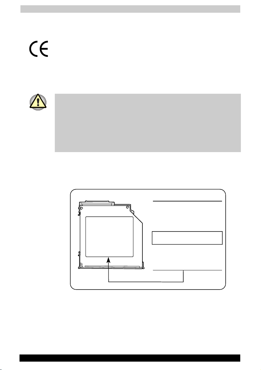
CD-RW/DVD-ROM/DVD-RAM drive safety instruction
** means any letters or numbers.
The CD-RW/DVD-ROM/DVD-RAM drive employs a laser system. To
ensure proper use of this product, please read this instruction manual
carefully and retain for future reference. Should the unit ever require
maintenance, contact an authorised service location.
Use of controls, adjustments or the performance of procedures other than
those specified may result in hazardous radiation exposure.
To prevent direct exposure to the laser beam, do not try to open the
enclosure.
Matsushita UJ-810
Location of the required label
PRODUCT IS CERTIFIED BY THE
MANUFACTURER TO COMPLY
WITH DHHS RULES 21 CFR
SUBCHAPTER J APPLICABLE AT
DATE OF MANUFACTURE.
MANUFACTURED:
Kyushu Matsushita Electric Co., Ltd.
1-62 4-Chome Minoshima,
Fukuoka,JapanHakata-Ku
Satellite 2430 Series iii
Page 4
User's Manual
CLASS 1 LASER PRODUCT
LASER KLASSE 1 PRODUKT
TO EN 60825-1
CAUTION: This appliance contains a laser system and is
classified as a “CLASS 1 LASER PRODUCT.” To use this
model properly, read the instruction manual carefully and keep
this manual for your future reference. In case of any trouble
with this model, please contact your nearest “AUTHORIZED
service station.” To prevent direct exposure to the laser beam,
do not try to open the enclosure.
CAUTION: USE OF CONTROLS OR ADJUSTMENTS OR
PERFORMANCE OF PROCEDURES OTHER THAN THOSE
SPECIFIED IN THE OWNER’S MANUAL MAY RESULT IN
HAZARDOUS RADIATION EXPOSURE.
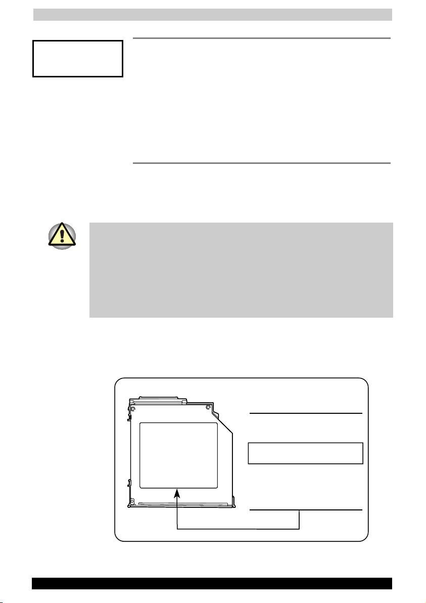
DVD-ROM drive safety instruction
** means any letters or numbers.
The DVD-ROM drive employs a laser system. To ensure proper use of this
product, please read this instruction manual carefully and retain for future
reference. Should the unit ever require maintenance, contact an
authorised service location.
Use of controls, adjustments or the performance of procedures other than
those specified may result in hazardous radiation exposure.
To prevent direct exposure to the laser beam, do not try to open the
enclosure.
Matsushita SR-8177
Location of the required label
COMPLIES WITH FDA RADIATION
PERFORMANCE STANDARDS, 21 CFR
SUBCHAPTER J.
MANUFACTURED:
Manufactured by
Matsushita-Kotobuki Electronics
Industries LTD.
2131 Minamikata, Kawauchi-Cho.
Onsen-Gun, Ehime 791-0395 Japan
Satellite 2430 Series iv
Page 5
User's Manual
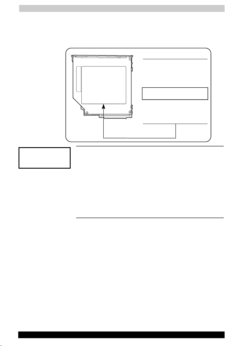
TOSHIBA SD-C2612
Location of the required label
PRODUCT IS CERTIFIED BY THE
MANUFACTURER TO COMPLY
WITH DHHS RULES 21 CFR
SUBCHAPTER J APPLICABLE AT
DATE OF MANUFACTURE.
MANUFACTURED:
TOSHIBA CORPORATION
1-1, SHIBAURA 1-CHOME
MINATO-KU, TOKYO 105-8001,
JAPAN
CLASS 1 LASER PRODUCT
LASER KLASSE 1 PRODUKT
TO EN 60825-1
CAUTION: This appliance contains a laser system and is
classified as a “CLASS 1 LASER PRODUCT.” To use this
model properly, read the instruction manual carefully and keep
this manual for your future reference. In case of any trouble
with this model, please contact your nearest “AUTHORIZED
service station.” To prevent direct exposure to the laser beam,
do not try to open the enclosure.
CAUTION: USE OF CONTROLS OR ADJUSTMENTS OR
PERFORMANCE OF PROCEDURES OTHER THAN THOSE
SPECIFIED IN THE OWNER’S MANUAL MAY RESULT IN
HAZARDOUS RADIATION EXPOSURE.
Satellite 2430 Series v
Page 6
User's Manual
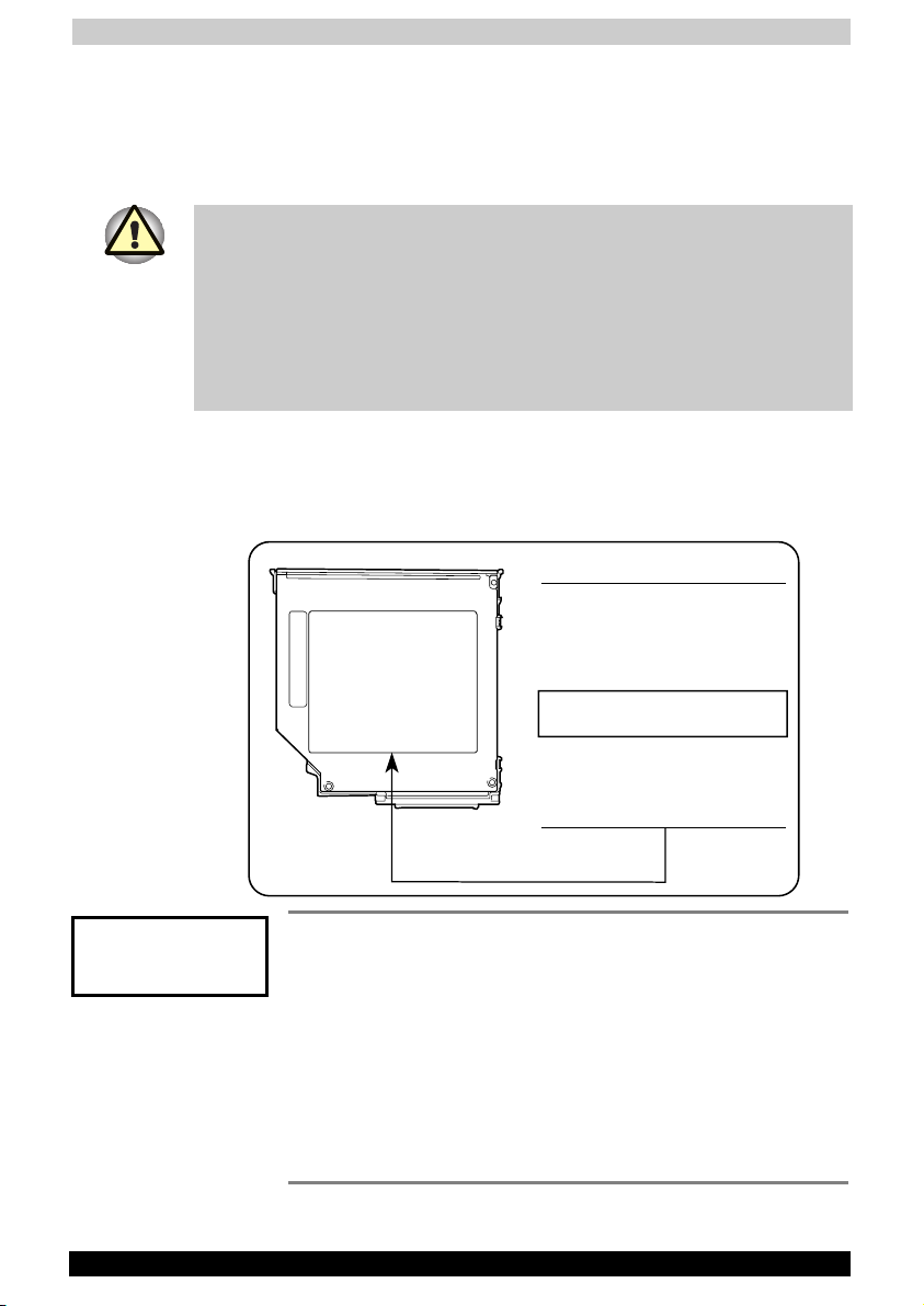
CD-RW/DVD-ROM/DVD-R/-RW drive safety
instruction
** means any letters or numbers.
The CD-RW/DVD-ROM,DVD-R/-RW drive employs a laser system. To
ensure proper use of this product, please read this instruction manual
carefully and retain for future reference. Should the unit ever require
maintenance, contact an authorised service location.
Use of controls, adjustments or the performance of procedures other than
those specified may result in hazardous radiation exposure.
To prevent direct exposure to the laser beam, do not try to open the
enclosure.
TOSHIBA SD-R6012
Location of the required label
PRODUCT IS CERTIFIED BY THE
MANUFACTURER TO COMPLY
WITH DHHS RULES 21 CFR
SUBCHAPTER J APPLICABLE AT
DATE OF MANUFACTURE.
MANUFACTURED:
TOSHIBA CORPORATION
1-1, SHIBAURA 1-CHOME
MINATO-KU, TOKYO 105-8001,
JAPAN
CLASS 1 LASER PRODUCT
LASER KLASSE 1 PRODUKT
TO EN 60825-1
CAUTION: This appliance contains a laser system and is
classified as a “CLASS 1 LASER PRODUCT.” To use this
model properly, read the instruction manual carefully and keep
this manual for your future reference. In case of any trouble
with this model, please contact your nearest “AUTHORIZED
service station.” To prevent direct exposure to the laser beam,
do not try to open the enclosure.
CAUTION: USE OF CONTROLS OR ADJUSTMENTS OR
PERFORMANCE OF PROCEDURES OTHER THAN THOSE
SPECIFIED IN THE OWNER’S MANUAL MAY RESULT IN
HAZARDOUS RADIATION EXPOSURE.
Satellite 2430 Series vi
Page 7

User's Manual
Modem warning notice
Conformity Statement
The equipment has been approved to [Commission Decision “CTR21”] for
pan-European single terminal connection to the Public Switched
Telephone Network (PSTN).
However, due to differences between the individual PSTNs provided in
different countries/regions the approval does not, of itself, give an
unconditional assurance of successful operation on every PSTN network
termination point.
In the event of problems, you should contact your equipment supplier in
the first instance.
Network Compatibility Statement
This product is designed to work with, and is compatible with the
following networks. It has been tested to and found to conform with the
additional requirements contained in EG 201 121.
Germany - ATAAB AN005, AN006, AN007, AN009, AN010,
and DE03, 04, 05, 08, 09, 12, 14, 17
Greece - ATAAB AN005, AN006 and GR01, 02, 03, 04
Portugal - ATAAB AN001, 005, 006, 007, 011 and
P03, 04, 08, 10
Spain - ATAAB AN005, 007, 012, and ES01
Switzerland - ATAAB AN002
All other
countries/regions
Specific switch settings or software setup are required for each network,
please refer to the relevant sections of the user guide for more details.
The hookflash (timed break register recall) function is subject to separate
national type approval. It has not been tested for conformity to national
type regulations, and no guarantee of successful operation of that
specific function on specific national networks can be given.
Satellite 2430 Series vii
- ATAAB AN003, 004
Page 8

User's Manual
General Precautions
TOSHIBA computers are designed to optimise safety, minimise strain and
withstand the rigors of portability. However, certain precautions should be
observed to further reduce the risk of personal injury or damage to the
computer.
Be certain to read the general precautions below and to note the cautions
included in the text of the manual. Please also refer to the Safety
Instruction Manual.
Stress injury
Carefully read the Safety Instruction Manual. It contains information on
prevention of stress injuries to your hands and wrists that can be caused
by extensive keyboard use. Chapter 3, Getting Started, also includes
information on work space design, posture and lighting that can help
reduce physical stress.
Heat Warning
■ Avoid prolonged physical contact with the bottom of the computer. If
the computer is used for long periods, its surface can become very
warm. While the temperature will not feel hot to the touch, if you
maintain physical contact with the computer for a long time (if you rest
the computer on your lap, for example) your skin might suffer low-heat
injury.
■ If the computer has been used for a long time, avoid direct contact
with the metal plate supporting the I/O ports. It can become hot.
■ The surface of the AC adaptor can become hot when in use. This
condition does not indicate a malfunction. If you need to transport the
AC adaptor, disconnect it and let it cool before moving it.
■ Do not lay the AC adaptor on a material that is sensitive to heat. The
material could be damaged.
Mobile phones
Use of mobile phones can interfere with the PC sound system. The PC
operation is not impaired but it is recommended that a distance of 30 cm
is maintained between the PC & the mobile phone.
Pressure or impact damage
Do not apply heavy pressure to the computer or subject it to strong
impact. Excessive pressure or impact can cause damage to computer
components or otherwise cause malfunctions.
Satellite 2430 Series viii
Page 9

User's Manual
PC Card overheating
Some PC Cards can become hot with prolonged use. If two cards are
installed, both can become hot even if only one is used extensively.
Overheating of a PC Card can result in errors or instability in the PC Card
operation. Also be careful when you remove a PC Card that has been
used for a long time.
CE compliance
This product and the original options are designed to observe the related
EMC (Electromagnetic compatibility) and safety standards. However,
TOSHIBA should not guarantee that this product still observes these EMC
standards if options or cables not produced by TOSHIBA are connected
or implemented. In this case the persons who have connected /
implemented those options / cables have to assure that the system
(PC plus options / cables) still fulfils the required standards. To avoid in
general EMC problems following advice should be observed:
■ Only CE marked options should be connected / implemented
■ Only best shielded cables should be connected
Working environment
This product was designed to fulfil the EMC (electromagnetic
compatibility) requirements to be observed for so-called "Residential,
commercial and light industry environments".
TOSHIBA do not approve the use of this product in working environments
other than the above mentioned "Residential, commercial and light
industry environments".
For example, the following environments are not approved:
■ Industrial Environments (environments with a mains voltage >230V~)
■ Medical Environments
■ Automotive Environments
■ Aircraft Environments
If this product is supplied with a network port, please refer to the
paragraph "Network connection".
Any consequences resulting from the use of this product in working
environments that are not approved are not the responsibility of TOSHIBA
Europe GmbH.
Satellite 2430 Series ix
Page 10

User's Manual
The consequences of the use of this product in non-approved working
environments may be:
■ Interference with other devices or machines in the near surrounding
area
■ Malfunction of, or data loss from, this product caused by disturbances
generated by other devices or machines in the near surrounding area
Therefore TOSHIBA strongly recommend that the electromagnetic
compatibility of this product should be suitably tested in all non-approved
working environments before use. In the case of automobiles or aircraft,
the manufacturer or airline respectively should be asked for permission
before use of this product.
Furthermore, for general safety reasons, the use of this product in
environments with explosive atmospheres is not permitted.
Network connection (class A warning)
If this product has networking capabilities and will be connected to a
network, Class A radiation limits will be observed (in accordance with
technical conventions). This means that if the product will be used in a
domestic environment, other devices in the near surrounding may suffer
interference. Consequently, please do not use this product in such
environments (for example a living room), otherwise you could be held
responsible for any ensuing interference.
Central Processing Unit (“CPU”) Performance Disclaimer:
CPU performance in your computer product may vary from specifications
under the following conditions:
■ use of certain external peripheral products
■ use of battery power instead of AC power
■ use of certain multimedia games or videos with special effects
■ use of standard telephone lines or low speed network connections
■ use of complex modelling software, such as high end computer aided
design applications
■ use of computer in areas with low air pressure (high altitude > 1,000
meters or > 3,280 feet above sea level)
■ use of computer at temperatures outside the range of 5ºC to 35ºC
(41ºF to 95ºF) or > 25ºC (77ºF) at high altitude (all temperature
references are approximate).
Under some conditions, your computer product may automatically shutdown. This is a normal protective feature designed to reduce the risk of
lost data or damage to the product when used outside recommended
conditions. To avoid risk of lost data, always make back-up copies of
data by periodically storing it on an external storage medium. For
optimum performance, use your computer product only under
recommended conditions. Read additional restrictions in bundled
documents. Contact Toshiba Service and Support for more information.
Satellite 2430 Series x
Page 11

User's Manual
Information on the secure use of the
CD-RW/DVD-RW
Please adhere to the following information on the use of the
CD-RW/DVD-RW to minimise the risk of unsuccessful storing process. As
the storing may be unsuccessful despite your adhering to these
information, for example because of a defective storing medium, you
should even if the software indicates a successful storage, always check
if the data has been stored successfully.
Important Notice
Copyrighted works including, but not limited to music, video, computer
program, databases are protected by copyright laws. Unless specifically
permitted under applicable copyright laws, you cannot copy, modify,
assign, transmit or otherwise dispose of any copyrighted work with the
consent of the owner of the copyright.
Please take notice that unauthorized copying, modification, assignment,
transmission and disposition may be subject to claims for damages and
penalties.
Satellite 2430 Series xi
Page 12

User's Manual
About TOSHIBA Wireless Solution
Wireless LAN Card Types
The Wireless LAN Card is a wireless network card that complies with the
IEEE 802.11 standard on wireless LANs (Revision B). The Wireless LAN
Card supports data rates up to 11 Mbit/s.
■ Wi-Fi (Wireless Fidelity) certified by the Wireless Ethernet
Compatibility Alliance (WECA). This means that your Wireless
hardware will communicate with other vendors’ IEEE 802.11
compliant wireless LAN product.
■ Fully compatible with any other wireless LAN system based on Direct
Sequence Spread Spectrum (DSSS) radio technology that complies
with the “IEEE 802.11 standard on wireless LANs (Revision B).
Wireless LAN cards
The Wireless LAN Card supports the following wireless LAN features:
■ Automatic Transmit Rate Select mechanism in the transmit range of
11, 5.5, 2 and 1 Mbit/s.
■ Frequent Channel Selection (2.4 GHz).
■ Roaming over multiple channels.
■ Card Power Management.
■ Wired Equivalent Privacy (WEP) data encryption, based on the 128 bit
RC4 encryption algorithm as defined in the IEEE 802.11 standard on
wireless LANs.
Satellite 2430 Series xii
Page 13

User's Manual
Wireless Interoperability
The TOSHIBA Wireless LAN Mini PCI Card products are designed to be
interoperable with any Wireless LAN product that is based on Direct
Sequence Spread Spectrum (DSSS) radio technology, and is compliant
to:
■ The IEEE 802.11 Standard on Wireless LANs (Revision B), as defined
and approved by the Institute of Electrical and Electronics Engineers.
■ The Wireless Fidelity (WiFi) certification as defined by the WECA
Wireless Ethernet Compatibility Alliance.
Wireless LAN and your Health
Wireless LAN products, like other radio devices, emit radio frequency
electromagnetic energy. The level of energy emitted by Wireless LAN
devices however is far much less than the electromagnetic energy
emitted by wireless devices like for example mobile phones.
Because Wireless LAN products operate within the guidelines found in
radio frequency safety standards and recommendations, TOSHIBA
believes Wireless LAN is safe for use by consumers. These standards and
recommendations reflect the consensus of the scientific community and
result from deliberations of panels and committees of scientists who
continually review and interpret the extensive research literature.
In some situations or environments, the use of Wireless LAN may be
restricted by the proprietor of the building or responsible representatives
of the organisation. These situations may for example include:
■ Using the Wireless LAN equipment on board of aeroplanes, or
■ In any other environment where the risk of interference to other
devices or services is perceived or identified as harmful.
If you are uncertain of the policy that applies on the use of wireless
devices in a specific organisation or environment (e.g. airports), you are
encouraged to ask for authorisation to use the Wireless LAN device prior
to turning on the equipment.
Safety Instruction for Wireless Products
If your computer has wireless function, all safety instructions must be
read carefully and must be fully understood, before attempting to use our
Wireless Products.
This manual contains the safety instructions that must be observed in
order to avoid potential hazards that could result in personal injuries or
could damage your Wireless Products.
Satellite 2430 Series xiii
Page 14

User's Manual
Limitation of Liability
For damage occurring due to an earthquake or thunder, fire beyond our
responsibility, action by third party, other accident, intentional or
accidental mistakes by a user, misuse, use under abnormal conditions,
we do not take any responsibility.
For incidental damage (loss of business profit, business interruption, etc.)
occurring due to use or disability of the product, we do not take any
responsibility.
For damage occurring due to non observance of the contents described
in the instruction manual, we do not take any responsibility.
For damage occurring due to erroneous operation or hang up caused by
use in combination with products not related to our company, we do not
take any responsibility.
Usage Restrictions
Do not use the Wireless Products for controlling equipment:
■ Equipment directly linked with human life corresponds to the
following.
■ Medical equipment such as life support systems, equipment used
in operations, etc.
■ Exhaust systems for gases such as poisonous gas etc. and
exhaust systems for smoke.
■ Equipment that must be set up in compliance with various laws
such as the Fire Services Act, the Construction Standard Act, etc.
■ Equipment corresponding to that mentioned above.
■ Equipment linked with human safety or having a serious influence on
the safe maintenance of public function, etc., because it is not
designed or manufactured for this type of use.
■ Traffic control equipment for air, railroad, road, marine transport,
etc.
■ Equipment used in atomic power plants etc.
■ Equipment corresponding to that mentioned above.
Satellite 2430 Series xiv
Page 15

User's Manual
WARNING
Turn OFF the Wireless Communication switch of Wireless Products in a
congested place, such as a crowded commuter train.
Keep this product away from a cardiac pacemaker at least 22cm.
Radio waves can potentially affect cardiac pacemaker operation, thereby
causing respiratory troubles.
Turn OFF the Wireless Communication switch inside a medical facility or
near medical electric equipment. Do not bring medical electric equipment
close to the product.
Radio waves can potentially affect medical electric equipment, thereby
causing an accident due to malfunction.
Turn OFF the Wireless Communication switch near an automatic door, fire
alarm or other automatic control equipment.
Radio waves can potentially affect automatic control equipment, thereby
causing an accident due to malfunction.
Do not turn ON the Wireless Communication switch in aircraft or in places
that generate or can generate radio interference.
Radio waves can potentially affect them, causing an accident due to
malfunction.
Monitor possible radio interference or other troubles to other equipment
while the product is used. If any effect is caused, turn OFF the Wireless
Communication switch.
Otherwise, radio waves can potentially affect other equipment, thereby
causing an accident due to malfunction.
When using the product in a car, check with the automobile dealer if the
car has an adequate electromagnetic compatibility (EMC).
Radio waves of the product can potentially hamper safe driving.
Depending on car model, the product can rarely affect car electronic
equipment if it is used in a car.
NOTE
Do not use the product in the following places:
Places near a microwave oven where a magnetic field generates and
places where static electricity or radio interference generates.
Depending on environment, radio waves can not reach to the product.
Satellite 2430 Series xv
Page 16

User's Manual
Regulatory Information
The TOSHIBA Wireless LAN Mini PCI Card must be installed and used in
strict accordance with the manufacturer’s instructions as described in the
user documentation that comes with the product. This device complies
with the following radio frequency and safety standards.
Canada – Industry Canada (IC)
This device complies with RSS 210 of Industry Canada.
Operation is subject to the following two conditions: (1) this device may
not cause interference, and (2) this device must accept any interference,
including interference that may cause undesired operation of this device.”
L’utilisation de ce dispositif est autorisée seulement aux conditions
suivantes : (1) il ne doit pas produire de brouillage et (2) l’utilisateur du
dispositif doit étre prét à accepter tout brouillage radioélectrique reçu,
même si ce brouillage est susceptible de compromettre le
fonctionnement du dispositif.
Europe – EU Declaration of Conformity
This device complies with the essential requirements of the R&TTE
Directive 1999/5/EC with essential test suites as per standards:
■ EN 60950 Safety of Information Technology equipment
■ ETS 300 328 Technical requirements for radio equipment
■ ETS 300 826 General EMC requirements for radio equipment.
Satellite 2430 Series xvi
Page 17

User's Manual
Belgium/
België/Belgique
For outdoor usage only channel 10 (2457 MHz)
and 11 (2462 MHz) is allowed.
For private usage outside buildings across public
grounds over less than 300m no special
registration with IBPT/BIPT is required.
Registration to IBPT/BIPT is required for private
usage outside buildings across public grounds
over more than 300m. An IBPT/BIPT license is
required for public usage outside building.
For registration and license please contact
IBPT/BIPT.
Gebruik buiten gebouw alleen op kanalen 10
(2457 MHz) en 11 (2462 MHz). Voor privégebruik buiten gebouw over publieke groud over
afstand kleiner dan 300m geen registratie bij
BIPT/IBPT nodig; voor gebruik over afstand
groter dan 300m is wel registratie bij BIPT/IBPT
nodig. Voor publiek gebruik buiten gebouwen is
licentie van BIPT/IBPT verplicht. Voor registratie
of licentie kunt u contact opnemen met BIPT.
L’utilisation en extérieur est autorisé sur le canal
10 (2457 MHz) et 11 (2462 Mhz).
Dans le cas d’une utilisation privée, à l’extérieur
d’un bâtiment, au-dessus d’un espace public,
aucun enregistrement n’est nécessaire pour une
distance de moins de 300m. Pour une distance
supérieure à 300m un enregistrement auprès de
I’IBPT est requise. Pour une utilisation publique à
I’extérieur de bâtiments, une licence de I’IBPT
est requise. Pour les enregistrements et licences,
veuillez contacter I’IBPT.
Germany/
Deutschland
License required for outdoor installations. Check
with reseller for procedure to follow
Anmeldung im Outdoor-Bereich notwendig, aber
nicht genehmigungspflichtig. Bitte mit Händler
die Vorgehensweise abstimmen.
Satellite 2430 Series xvii
Page 18

User's Manual
France Restricted frequency band: only channels 10 and
11 (2457 MHz and 2462 MHz respectively) may
be used in France. License required for every
installation, indoor and outdoor installations.
Please contact ART for procedure to follow.
Bande de fréquence restreinte : seuls les canaux
10 à 11 (2457 et 2462 MHz respectivement)
doivent être utilisés en France.
Toute utilisation, qu’elle soit intérieure ou
extérieure, est soumise à autorisation. Vous
pouvez contacter I’Autorité de Régulation des
Télécommuniations (http://www.art-telecom.fr)
pour la procédure à suivre.
Italy/Italia License required for indoor use. Use with
outdoor installations not allowed
E’necessaria la concessione ministeriale anche
per l’uso interno.
Verificare con i rivenditori la procedura da
seguire. L’uso per installazione in esterni non e’
permessa.
Nederland License required for outdoor installations. Check
with reseller for procedure to follow
Licentie verplicht voor gebruik met
buitenantennes. Neem contact op met verkoper
voor juiste procedure
USA-Federal Communications Commission (FCC)
This device complies with Part 15 of FCC Rules. Operation of the devices
in a Wireless LAN System is subject to the following two conditions:
■ This device may not cause harmful interference.
■ This device must accept any interference that may cause undesired
operation.
TOSHIBA is not responsible for any radio or television interference
caused by unauthorized modification of the devices included with this
TOSHIBA Wireless LAN Mini PCI Card, or the substitution or attachment
of connecting cables and equipment other than specified by TOSHIBA.
The correction of interference caused by such unauthorized modification,
substitution or attachment will be the responsibility of the user.
Satellite 2430 Series xviii
Page 19

User's Manual
Caution: Exposure to Radio Frequency Radiation.
The Toshiba Wireless LAN Mini PCI Card will be installed with one of two
types of antennas. Both antenna types, when installed are located at the
upper edge of the LCD screen.
For both antennas, the radiated output power of the TOSHIBA Wireless
LAN Mini PCI Card is far below the FCC radio frequency exposure limits.
Nevertheless, the TOSHIBA Wireless LAN Mini PCI Card shall be used in
such a manner that the potential for human contact during normal
operation is minimized. In normal operating configuration, the LCD in the
upright position, the distance between the antenna and the user should
not be less than 20cm.
Refer to the Regulatory Statements as identified in the documentation
that comes with those products for additional information.
Relevant transmitters include FCC IDs: CJ6PA3171WL, CJ6PA3121BT.
Taiwan
Article 14 Unless approved, for any model accredited low
power radio frequency electric machinery, any
company, trader or user shall not change the
frequency, increase the power or change the
features and functions of the original design.
Article 17 Any use of low power radio frequency electric
machinery shall not affect the aviation safety and
interfere with legal communications. In event that
any interference is found, the use of such electric
machinery shall be stopped immediately, and
reusing of such products can be resumed until
no interference occurs after improvement.
The legal communications mentioned in the
above item refer to radio communications
operated in accordance with telecommunication
laws and regulations.
Low power radio frequency electric machinery
shall resist against interference from legal
communications or from industrial, scientific and
medical radio emission electric machinery.
Satellite 2430 Series xix
Page 20
User's Manual
Using this equipment in Japan
In Japan, the frequency bandwidth of 2,400~2,483.5MHz for second
generation low-power data communication systems such as this
equipment overlaps that of mobile object identification systems (premises
radio station and specified low-power radio station).
1. Sticker
Please put the following sticker on devices incorporating this product.
In the frequency bandwidth of this equipment, industrial device,
scientific device, medical device like microwave oven, licensed
premises radio station and non-licensed specified low-power
radio station for mobile object identification system (RF-ID) that is
used in product line of factories, (Other Radio Stations) are used.
1. Please make sure before using this equipment that no Other
Radio Stations are used in the neighbourhood.
2. In case that RF interference occurs to Other Radio Stations
from this equipment, please change promptly the frequency
for use, place to use, or stop emitting Radio.
3. Please contact TOSHIBA Direct PC if you have a problem,
such as interference from this equipment to Other Radio
Stations.
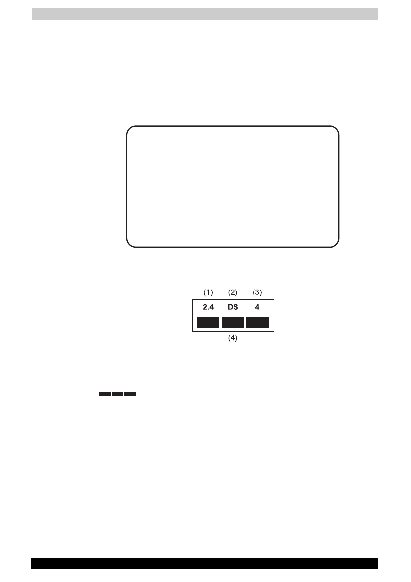
2. Indication
The indication shown below appears on this equipment.
(1) 2.4 : This equipment uses a frequency of 2.4GHz.
(2) DS : This equipment uses DS-SS modulation.
(3) 4 : The interference range of this equipment is less than 40m.
(4)
: This equipment uses a frequency bandwidth from
2,400mhz to 2,483.5MHz.
It is impossible to avoid the band of mobile object
identification systems.
Satellite 2430 Series xx
Page 21

User's Manual
Device Authorisation
This device obtains the Technical Regulation Conformity Certification and
the Technical Conditions Compliance Approval, and it belongs to the
device class of radio equipment of low-power data communication
system radio station stipulated in the Radio Law and the
Telecommunications Business Law of Japan.
The Name of the radio equipment: MPCI3A-20/R
JAPAN APPROVALS INSTITUTE FOR
TELECOMMUNICATIONS EQUIPMENT
TELECOM ENGINEERING CENTER Approval Number: 01NY A1088
The following restrictions apply:
■ Do not disassemble or modify the device.
■ Do not install the embedded wireless module into other device.
Approval Number: D01-1128JP
Satellite 2430 Series xxi
Page 22

Table of Contents
Satellite 2430 Series
Table of Contents
Preface ...................................................................................... xxix
Manual contents.................................................................................. xxix
Conventions.......................................................................................... xxx
Abbreviations.................................................................................... xxx
Icons................................................................................................. xxx
Keys.................................................................................................. xxx
Key operation ...................................................................................xxxi
Display..............................................................................................xxxi
Messages .........................................................................................xxxi
Chapter 1 Introduction..............................................................1-1
Equipment checklist .............................................................................1-1
Hardware ...........................................................................................1-1
Software ............................................................................................1-2
Documentation ..................................................................................1-2
Features .................................................................................................1-3
Special features.....................................................................................1-7
Utilities ...................................................................................................1-9
Options.................................................................................................1-10
Satellite 2430 Series xxii
Page 23

Table of Contents
Chapter 2 The Grand Tour........................................................2-1
Front with the display closed ...............................................................2-1
Left side..................................................................................................2-3
Right side ...............................................................................................2-4
Back side ...............................................................................................2-5
Underside...............................................................................................2-7
Front with the display open..................................................................2-8
Indicators .............................................................................................2-10
Drives ...................................................................................................2-12
3 ½" diskette drive...........................................................................2-12
CD-RW/DVD-ROM drive .................................................................2-13
AC adaptor...........................................................................................2-14
Chapter 3 Getting Started ........................................................3-1
Setting up your work space .................................................................3-1
General conditions.............................................................................3-2
Placement of computer .....................................................................3-2
Seating and posture ..........................................................................3-3
Lighting..............................................................................................3-4
Work habits .......................................................................................3-4
Connecting the AC adaptor..................................................................3-5
Opening the display ..............................................................................3-6
Turning on the power............................................................................3-7
Starting up for the first time .................................................................3-7
Turning off the power ...........................................................................3-8
Shut Down mode (Boot mode) ..........................................................3-8
Hibernation mode ..............................................................................3-8
Standby mode .................................................................................3-10
Restarting the computer.....................................................................3-12
Restoring the preinstalled software ..................................................3-12
Restoring the complete system.......................................................3-12
Restoring TOSHIBA utilities and drivers ..........................................3-12
Satellite 2430 Series xxiii
Page 24

Table of Contents
Chapter 4 Operating Basics.....................................................4-1
Using the Touch pad.............................................................................4-1
Changing SelectBay modules ..............................................................4-3
Removing a module...........................................................................4-3
Installing a module.............................................................................4-3
Using optical media drives ...................................................................4-3
Safety Precautions ............................................................................4-4
Loading discs ....................................................................................4-5
Removing discs .................................................................................4-8
CD/Digital Mode button.....................................................................4-9
CD/DVD/Audio control buttons .......................................................4-10
Writing DVD/CDs .................................................................................4-10
Before writing ..................................................................................4-10
When writing or rewriting.................................................................4-11
Media care ...........................................................................................4-12
CDs/DVDs .......................................................................................4-12
Diskette care....................................................................................4-12
Using the internal modem ..................................................................4-13
IMPORTANT SAFETY INSTRUCTIONS...........................................4-13
Region selection ..............................................................................4-14
Properties menu ..............................................................................4-15
Connecting ......................................................................................4-16
LAN .......................................................................................................4-17
Connecting LAN cable.....................................................................4-17
Disconnecting LAN cable ................................................................4-18
Wireless LAN .......................................................................................4-18
Wireless communication switch ......................................................4-19
Wireless communication LED..........................................................4-19
TV-Out ..................................................................................................4-21
Cleaning the computer .......................................................................4-21
Moving the computer..........................................................................4-21
Heat dispersal......................................................................................4-22
Satellite 2430 Series xxiv
Page 25

Table of Contents
Chapter 5 The Keyboard ..........................................................5-1
Typewriter keys .....................................................................................5-1
F1…F12 function keys...........................................................................5-2
Soft Keys: Alt Gr Key Combinations....................................................5-2
Soft keys: Fn key combinations ...........................................................5-2
Emulating keys on enhanced keyboard.............................................5-3
Hotkeys .............................................................................................5-4
Windows special keys .......................................................................5-6
Keypad overlay ......................................................................................5-6
Turning on the overlays .....................................................................5-6
Temporarily using normal keyboard (overlay on)...............................5-7
Temporarily using overlay (overlay off) ..............................................5-8
Temporarily changing modes ............................................................5-8
Generating ASCII characters................................................................5-8
Chapter 6 Power and Power-Up Modes.................................6-1
Power conditions ..................................................................................6-1
Power indicators ...................................................................................6-2
Battery indicator ................................................................................6-2
DC IN indicator ..................................................................................6-3
Power indicator..................................................................................6-3
Battery types..........................................................................................6-3
Battery pack ......................................................................................6-3
Real Time Clock battery ....................................................................6-4
Care and use of the battery pack ........................................................6-4
Safety precautions.............................................................................6-4
Charging the batteries .......................................................................6-7
Monitoring battery capacity...............................................................6-9
Maximising battery operating time ....................................................6-9
Retaining data with power off (standby mode)................................6-10
Extending battery life.......................................................................6-10
Replacing the battery pack ................................................................6-10
Removing the battery pack .............................................................6-10
Installing the battery pack ...............................................................6-12
Power-up modes .................................................................................6-13
Panel power off/on..............................................................................6-13
System automatic Standby/Hibernation ...........................................6-13
Satellite 2430 Series xxv
Page 26

Table of Contents
Chapter 7 Optional Devices .....................................................7-1
PC Cards ................................................................................................7-2
Installing a PC Card...........................................................................7-2
Removing a PC Card.........................................................................7-3
SD Cards ................................................................................................7-4
Installing an SD Card.........................................................................7-4
Removing an SD Card.......................................................................7-5
Memory expansion................................................................................7-6
Installing a memory module...............................................................7-6
Removing a memory module.............................................................7-8
Additional battery pack.........................................................................7-9
Additional AC adaptor...........................................................................7-9
Parallel printer .......................................................................................7-9
External monitor..................................................................................7-10
Television .............................................................................................7-10
i.LINK (IEEE1394) .................................................................................7-12
Precautions......................................................................................7-12
Connecting ......................................................................................7-13
Disconnecting..................................................................................7-13
Security lock ........................................................................................7-14
Satellite 2430 Series xxvi
Page 27

Table of Contents
Chapter 8 Troubleshooting ......................................................8-1
Problem solving process ......................................................................8-1
Preliminary checklist..........................................................................8-2
Analysing the problem.......................................................................8-2
Hardware and system checklist...........................................................8-3
System start-up.................................................................................8-4
Self test..............................................................................................8-4
Power ................................................................................................8-4
Keyboard ...........................................................................................8-7
LCD panel..........................................................................................8-7
Hard disk drive ..................................................................................8-8
CD-RW/DVD-ROM drive ...................................................................8-8
DVD-R/-RW drive (optional).............................................................8-10
DVD-RAM drive (optional)................................................................8-11
Diskette drive...................................................................................8-13
Infrared port.....................................................................................8-13
Printer ..............................................................................................8-14
PC Card...........................................................................................8-14
SD Card...........................................................................................8-14
Sound system..................................................................................8-15
Pointing device ................................................................................8-15
USB .................................................................................................8-16
TV output signal...............................................................................8-17
Standby/Hibernation........................................................................8-17
Memory expansion ..........................................................................8-18
Modem ............................................................................................8-18
LAN..................................................................................................8-19
Wireless LAN ...................................................................................8-19
Monitor ............................................................................................8-20
i.LINK (IEEE1394).............................................................................8-20
Memory expansion ..........................................................................8-21
If you need further assistance............................................................8-21
Before you call.................................................................................8-21
Where to write .................................................................................8-21
Satellite 2430 Series xxvii
Page 28

Table of Contents
Appendix A Specifications ......................................................A-1
Appendix B AC Power Cord and Connectors .......................B-1
Appendix C The TOSHIBA International Warranty ...............C-1
Appendix D Keyboard Layouts ...............................................D-1
Appendix E Display Controller and Modes............................ E-1
Appendix F If your computer is stolen ................................... F-1
Appendix G ASCII Character Codes ......................................G-1
Appendix H AT Commands .....................................................H-1
Appendix I S-registers .............................................................. I-1
Appendix J V.90 .........................................................................J-1
Appendix K Wireless LAN........................................................ K-1
Appendix L Internal Modem Guide......................................... L-1
Glossary...................................................................................... L-1
Index ........................................................................................... L-1
Satellite 2430 Series xxviii
Page 29

Preface
Satellite 2430 Series
Preface
Congratulations on your purchase of the Satellite 2430 series computer.
This powerful notebook computer provides excellent expansion
capability, including multimedia devices, and it is designed to provide
years of reliable, high-performance computing.
This manual tells how to set up and begin using your Satellite 2430 series
computer. It also provides detailed information on configuring your
computer, basic operations and care, using optional devices and
troubleshooting.
If you are a new user of computers or if you’re new to portable
computing, first read over the Introduction and The Grand Tour chapters
to familiarise yourself with the computer’s features, components and
accessory devices. Then read Getting Started for step-by-step
instructions on setting up your computer.
If you are an experienced computer user, please continue reading the
preface to learn how this manual is organised, then become acquainted
with this manual by browsing through its pages. Be sure to look over the
Special features section of the Introduction, to learn about features that
are uncommon or unique to the computer.
Manual contents
This manual is composed of eight chapters, twelve appendices, a
glossary, and an index.
Chapter 1, Introduction, is an overview of the computer’s features,
utilities, and options.
Chapter 2, The Grand Tour, identifies the components of the computer
and briefly explains how they function.
Chapter 3, Getting Started, provides a quick overview of how to begin
operating your computer and gives tips on safety and designing your
work area. Be sure to read the section on restoring the preinstalled
software.
Chapter 4, Operating Basics, includes instructions on using the following
devices: Touch pad, the optical media drives, the internal modem, LAN
and Wireless LAN. It also provides tips on care of the computer, diskettes
and DVD/CD-ROMs.
Satellite 2430 Series xxix
Page 30

Preface
Chapter 5, The Keyboard, describes special keyboard functions including
the keypad overlay and hotkeys.
Chapter 6, Power and Power-Up Modes, gives details on the computer’s
power resources.
Chapter 7, Optional Devices, describes the optional hardware available.
Chapter 8, Troubleshooting, suggests courses of action if the computer
doesn’t seem to be working properly.
The Appendices provide technical information about your computer.
The Glossary defines general computer terminology and includes a list of
acronyms used in the text.
The Index quickly directs you to the information contained in this manual.
Conventions
This manual uses the following formats to describe, identify, and highlight
terms and operating procedures.
Abbreviations
On first appearance, and whenever necessary for clarity, abbreviations
are enclosed in parentheses following their definition. For example: Read
Only Memory (ROM). Acronyms are also defined in the Glossary.
Icons
Icons identify ports, dials, and other parts of your computer. The indicator
panel also uses icons to identify the components it is providing
information on.
Keys
The keyboard keys are used in the text to describe many computer
operations. A distinctive typeface identifies the key top symbols as they
appear on the keyboard. For example, Enter identifies the Enter key.
Satellite 2430 Series xxx
Page 31

Preface
Key operation
Some operations require you to simultaneously use two or more keys. We
identify such operations by the key top symbols separated by a plus sign
(+). For example, Ctrl + C means you must hold down Ctrl and at the
same time press C. If three keys are used, hold down the first two and at
the same time press the third.
Display
S
ABC
Names of Windows® or icons or text
generated by the computer that appears on
its display screen is presented in the type
face you see to the left.
Text generated by the computer is usually
preceded by the screen icon.
Messages
Messages are used in this manual to bring important information to your
attention. Each type of message is identified as shown below.
Pay attention! A caution informs you that improper use of equipment or
failure to follow instructions may cause data loss or damage your
equipment.
Please read. A note is a hint or advice that helps you make best use of
your equipment.
Satellite 2430 Series xxxi
Page 32

Introduction
Satellite 2430 Series
Chapter 1
Introduction
This chapter provides an equipment checklist, and it identifies the
computer’s special features, utilities and options.
Some of the features described in this manual may not function properly if
you use an operating system that was not preinstalled by TOSHIBA.
Equipment checklist
Carefully unpack your computer. Save the box and packing materials for
future use. Check to make sure you have all the following items:
Hardware
■ Satellite 2430 Series Portable Personal Computer
■ Universal AC adaptor and power cord
■ Modular cable for modem
■ SelectBay Floppy Disk Drive
Satellite 2430 Series 1-1
Page 33

Introduction
Software
The following software preinstalled on your hard disk:
■ Windows XP Home Edition is preinstalled
The Windows XP preinstallation includes the following software:
■ Microsoft Windows XP Home Edition
■ TOSHIBA Utilities
■ Display Driver
■ Touch pad driver
■ Sound driver
■ Modem driver
■ DVD Video Player
■ Wireless LAN driver (Provided only if Wireless LAN is preinstalled.)
■ LAN driver
■ Infrared Device driver
■ Online manual
■ Supervisor Password utility
■ Product Recovery CD-ROM
■ Tools & Utilities CD-ROM
The system may not function properly if you use drivers that are not
preinstalled or distributed by TOSHIBA
Documentation
Your computer’s documentation:
■ Satellite 2430 Series Personal Computer User’s Manual
■ Satellite 2430 Series QuickStart
■ Microsoft Windows XP manual
■ Safety Instruction Manual
■ Warranty information
If any of the items are missing or damaged, contact your dealer
immediately.
Satellite 2430 Series 1-2
Page 34

Introduction
Features
The Satellite 2340 series computer uses TOSHIBA’s advanced Large
Scale Integration (LSI), Complementary Metal-Oxide Semiconductor
(CMOS) technology extensively to provide compact size, minimum
weight, low power usage, and high reliability. This computer incorporates
the following features and benefits:
Processor
Built-In This computer is equipped with an Intel®
Pentium
®
4 processor, which incorporates a
math co-processor and a 512 KB level 2 cache
memory. It also supports Intel Speedstep™
technology.
■ 2.5 GHz Intel
■ 2.6 GHz Intel
®
Pentium® 4 processor
®
Pentium® 4 processor
■ Other processors may be offered in the
future.
Chip Set
Chip Set Intel® 845PE, Intel®82801 PC87591 for Keyboard
Controller, Battery Management and RTC
OZ6933 for Card Bus PCMCIA Controller nVidia
GeForce4 420 Go mobile graphics controller
ALC202 for AC97 CODEC OZ168 for Direct CD
play controller TSB43AB21 for 1394 controller
Realtek 8100BL on-board LAN
Memory
Slots Two on-board 200-pin +2.5V DDR SO-DIMM
connectors with supporting DDR 266 memory
card. 512KB L2 Cache on CPU
Video RAM 32 MB provided for video display
BIOS
BIOS 512KB Flash ROM for system BIOS Suspend to
RAM/Disk Password protection Windows-ready
with PnP Hot keys for system control
Refreshable Complete ACPI 1.0b Function
Satellite 2430 Series 1-3
Page 35

Introduction
Power
Battery Pack 12-cel Li-Ion 18650 size smart battery pack
3.5 hour charging time to 100% capacity when
system is off. 12 hour charging time to 100 %
when system is on.
RTC Battery The computer has an internal battery to back up
the internal Real Time Clock (RTC) and calendar.
AC adaptor The universal AC adaptor provides power to the
system and recharges the batteries when they
are low. It comes with a detachable power cord.
Disks
Fixed hard disk Either one 40GB hard disk drive
Bus Master IDE
9.5m/m 2.5” HDD Support
Ultra 100 synchronous support DMA
SelectBay diskette
drive
Optical media drive 5.25” 12.7mm height CD-RW/DVD-ROM combo
Computers in this series can be configured with multiple types of optical
media drive. For more information on the optical media drives available,
talk to your dealer. More information on using the optical media drive can
be found in Chapter 4, Operating Basics.
Accommodates either 3 ½” 1.44 megabyte or
720 kilobyte diskettes and can be installed in the
SelectBay.
drive. It is installed in the SelectBay by default.
PC Card
PC Card One type III card socket or two type II card
sockets SRAM, OTPROM, FLASH ROM, mask
ROM MODEM/LAN Card
Card bus card
ACPI 1.0 compliant
Satellite 2430 Series 1-4
Page 36

Introduction
Ports
External monitor 15-pin analogue VGA port supports VESA
DDC2B compatible functions.
Universal Serial Bus The computer has three Universal Serial Bus
(USB) ports that comply with the USB 2.0
standard, which enables data transfer speeds
more than 40 times faster than USB 1.1 (which
this computer also supports.) The USB drives
may be used to transfer data at Low, Full, and
High speeds.
i.LINK (IEEE1394) This port enables high-speed data transfer
directly from external devices such as digital
video cameras.
Infrared The serial infrared port is compatible with the
Infrared Data Association (IrDA 1.1) standards. It
enables cableless 4 Mbps, 1.152 Mbps,
115.2 kbps, 57.6 kbps, 38.4 kbps, 19.2 kbps or
9.6 kbps data transfer with IrDA 1.1 compatible
external devices.
Multimedia
Sound system Incorporates a Wave Table Synthesizer for
advanced sound applications including 3D
games, DVD movie playback and Internet
communications.
Video-out and Lineout
TV-out button Sets your display device to TV (video-out). Press
Mode Control button Launches various CD, DVD and Digital audio
Audio/Video controls Let you use the computer’s fixed optical media
Satellite 2430 Series 1-5
Lets you transfer video and sound data to
external devices. Use the TV adaptor cable for
both video-out and line-out. Data output
depends on the type of device connected to the
TV adaptor cable.
it to switch back and forth between it and the
LCD.
functions. Refer to Chapter 4, Operating Basics,
for more details.
drive as a stand-alone audio CD-player or MP3
player. You can also use the buttons to control
the computer’s DVD video player when the
system is on.
Page 37

Introduction
Headphone jack Outputs analogue or digital audio.
Microphone jack A 3.5 mm mini microphone jack enables
connection of a three-conductor mini jack for
monaural microphone input.
Line-in jack A standard 3.5 mm line-in jack enables
connection of a stereo device for audio input.
Communications
Modem An internal modem provides capability for data
and fax communication. It supports V.90. The
speed of data transfer and fax depends on
analogue telephone line conditions. It has a
modem jack for connecting to a telephone line.
LAN The computer has built-in support for Ethernet
LAN (10 megabits per second, 10BASE-T) and
Fast Ethernet LAN (100 megabits per second
100BASE-Tx).
Wireless LAN An optional wireless LAN mini-PCI card is
compatible with other LAN systems based on
Direct Sequence Spread Spectrum radio
technology that complies with the IEEE 802.11
Standard (Revision B). It supports data transfer
up to 11 Mbits/s. It has a Frequency Channel
Selection (2.4 GHz) and allows roaming over
multiple channels.
TOSHIBA SelectBay
Modules TOSHIBA SelectBay is a single-drive bay that
accommodates a DVD-RAM, DVD-ROM,
DVD-R/RW drive, CD-RW/DVD-ROM combo
drive, SelectBay FDD, TOSHIBA SelectBay HDD
adaptor, TOSHIBA SelectBay 2nd battery pack
or Bridge media (for Memory
®
Stick
/SmartMedia/CompactFlash™ memory)
adaptor. The TOSHIBA Mobile Extension
enables hot docking of modules when you use a
plug and play operating system.
Security
Security Boot-up password protection
Single level password architecture (Supervisor.)
Satellite 2430 Series 1-6
Page 38

Introduction
Special features
The following features are either unique to TOSHIBA computers or are
advanced features, which make the computer more convenient to use.
Hotkeys Key combinations let you quickly modify the
system configuration directly from the keyboard
without running a system configuration program.
Display Automatic
Power off
HDD Automatic
Power off
System Automatic
Standby/Hibernation
Keypad Overlay A ten-key pad is integrated into the keyboard.
Intelligent Power
Supply
This feature automatically cuts off power to the
internal display when there is no input from the
keyboard or pointing device for a time specified.
Power is restored when any key is pressed or
when there is input from a pointing device. You
can specify the time in the TOSHIBA Power
Management Utility.
This feature automatically cuts off power to the
hard disk drive when it is not accessed for a time
specified. Power is restored when the hard disk
is accessed. You can specify the time in the
TOSHIBA Power Management Utility.
This feature automatically shuts down the
system in standby mode or Hibernation mode
when there is no input or hardware access for a
time specified. You can specify the time and
select either System Standby or System
Hibernate in the TOSHIBA Power Management
Utility.
Refer to the Keypad overlay section in
Chapter 5, Keyboard, for instructions on using
the keypad overlay.
A microprocessor in the computer’s intelligent
power supply detects the battery’s charge and
calculates the remaining battery capacity. It also
protects electronic components from abnormal
conditions, such as voltage overload from an AC
adaptor. You can monitor remaining battery
capacity through the TOSHIBA Power
Management Utility.
Battery Save Mode This feature lets you save battery power. You
can specify the Battery Save Mode in the
TOSHIBA Power Management Utility.
Instant Security A hotkey function blanks the screen providing
quick and easy data security.
Satellite 2430 Series 1-7
Page 39

Introduction
Panel Power Off/On This feature turns power to the computer off
when the display panel is closed and turns it
back on when the panel is opened. You can
specify the setting in the TOSHIBA Power
Management Utility.
Low Battery
Automatic
Hibernation
When battery power is exhausted to the point
that computer operation cannot be continued,
the system automatically enters Hibernation and
shuts down. You can specify the setting in the
TOSHIBA Power Management Utility.
Heat Dispersal The CPU has an internal temperature sensor that
automatically activates cooling procedures.
Refer to the Heat dispersal section in Chapter 4,
Operating Basics, for details on setting the
options for cooling methods.
Hibernation This feature lets you turn off the power without
exiting from your software. The contents of main
memory is saved to the hard disk, when you turn
on the power again, you can continue working
right where you left off. Refer to the Turning off
the power section in Chapter 3, Getting Started,
for details.
Standby In Standby mode, power to the system remains
on, but the CPU and all other devices are in
sleep mode. When the computer is in standby
mode, the Power LED glows orange. To enter
Standby mode click Start, click Shut Down,
select Standby and click OK. The computer
enters Standby mode regardless of the
Hibernate setting.
Before entering Standby mode, be sure to save your data.
Do not install or remove a memory module while the computer is in
Standby mode. The computer or the module could be damaged.
Do not remove the battery pack while the computer is in Standby mode.
Data in memory will be lost.
Satellite 2430 Series 1-8
Page 40

Introduction
Utilities
This section describes preinstalled utilities and tells how to start them. For
details on operations, refer to each utility’s online manual, help files or
readme files.
TOSHIBA Power
Management Utility
TOSHIBA Console TOSHIBA Console is a graphical user interface
DVD Video Player The DVD Video Player is used to play DVD-
Drag’n Drop CD This easy-to-use software lets you record CDs
There are two ways to display the Windows XP
Control Panel. The default is Category View.
TOSHIBA Power Management Utility is under the
Performance and Maintenance item.
that provides easy access to help and services.
It is the default function launched by the
TOSHIBA Console button.
Video. It has an on-screen interface and
functions. Click Start, point to All Programs,
point to InterVideo WinDVD, then click InterVideo
WinDVD.
with just a few mouse clicks. You can create
CDs in several formats including audio CDs that
can be played on a standard stereo CD player
and data CDs to store the files and folders on
your hard drive.
Satellite 2430 Series 1-9
Page 41

Introduction
Options
You can add a number of options to make your computer even more
powerful and convenient to use. The following options are available:
Memory Modules Two memory modules can be installed in the
computer.
Use only PC2100 compatible memory modules. See your TOSHIBA
dealer for details.
Battery Pack An additional battery pack can be purchased
from your TOSHIBA dealer. Use it as a spare to
increase your computer operating time.
AC Adaptor If you use your computer at more than one site
frequently, it may be convenient to purchase an
additional AC adaptor for each site so you will
not have to carry the adaptor with you.
Security Lock A slot is available to attach a security cable to
the computer to deter theft.
Wireless LAN Kit This option enables wireless LAN functions in
computers that do not have wireless
preinstalled. It is installed by dealers only.
USB FDD Kit Lets you attach a floppy diskette device to your
computer by means of a USB cable.
DVD-RAM Drive Kit Lets you add a modular DVD-RAM drive in place
of your existing CD-RW/DVD-ROM drive.
DVD-R/-RW Drive Kit Lets you add a modular DVD-R/-RW drive in
place of your existing CD-RW/DVD-ROM drive.
Satellite 2430 Series 1-10
Page 42

The Grand Tour
LEFT SPEAKER
CD/DVD EJECT
BUTTON
DISPLAY LATCHSYSTEM INDICATORS
CD-RW/DVD-ROM
DRIVE
RIGHT SPEAKER
CD/DVD/AUDIO CONTROL
BUTTONS
Satellite 2430 Series
Chapter 2
The Grand Tour
This chapter identifies the various components of your computer.
Become familiar with each component before you operate the computer.
Front with the display closed
The figure below shows the computer’s front with its display panel in the
closed position.
Front of the computer with display closed
System Indicators The system indicators provide icons for
Satellite 2430 Series 2-1
monitoring the status of Disc Player, Audio
Music, DC IN, Power, Battery, Built-in HDD and
Diskette/Optical Media drive. Details are given
later in this chapter.
Page 43

The Grand Tour
Left & Right
Speakers
Display Latch This latch secures the LCD panel in its closed
The front edges for both the left and right
speakers.
position. Slide the latch to open the display.
Mode Press this button to cycle between various CD,
MODE
DVD and audio functions. Refer to Chapter 4,
Operating Basics, for details.
Play/Pause Press this button to begin playing an audio CD, a
DVD Pause movie or digital audio files. This
button also acts as a Pause button. Refer to
Chapter 4, Operating Basics for details.
Stop Stops playing the CD, DVD or digital audio. Refer
Previous/Fast
Rewind
to Chapter 4, Operating Basics, for details.
Skips back to previous tracks. If held down while
a song is playing, it fast rewinds through it. Refer
to Chapter 4, Operating Basics, for details.
Next/Fast Forward Skips forward to previous tracks. If held down
while a song is playing, it fast forwards through
it. Refer to Chapter 4, Operating Basics, for
details.
If Random or Shuffle is selected in Windows Media Player, selecting Next
or Previous advances to a random selection.
CD-RW/DVD-ROM
Drive
The computer is configured with a full-size
optical media drive module that lets you run
either 12 cm (4.72") or 8 cm (3.15") discs without
using an adaptor. See the Drives section in this
chapter for technical specifications on the drive
and to Chapter 4, Operating Basics, for
information on using the drive and caring for
discs.
Satellite 2430 Series 2-2
Page 44

The Grand Tour
WIRELESS COMMUNICATION
SWITCH
MICROPHONE
LEFT SPEAKERHEADPHONE
VOLUME CONTROL
LINE INSECURITY LOCK
Left side
The figure below shows the computer's left side.
The left side of the computer
Security Lock A security cable attaches to this slot. The
optional security cable anchors your computer to
a desk or other large object to deter theft.
Off On
Wireless
communication LED
Wireless
communication
This LED glows when the wireless LAN functions
are on.
Slide this switch to turn the Wireless
communication power on and off.
switch
Headphone Jack A standard 3.5 mm mini headphone jack enables
connection of a stereo headphone (16 ohm
minimum) or other device for audio output. When
you connect headphones, the internal speakers
are automatically disabled.
Microphone Jack A standard 3.5 mm mini microphone jack
enables connection of a three-inch conductor
mini-jack for a monaural microphone.
Line-In Jack A standard 3.5 mm min line-in jack enables
connection of a stereo device for audio input.
Volume Control Use this dial to adjust the volume of the stereo
speakers.
Left Speaker The left audio speaker. Volume can be controlled
either with the volume dial on the left side of the
computer, or with the Volume setting in Windows
XP.
Satellite 2430 Series 2-3
Page 45

The Grand Tour
INFRARED PORTi.LINK PORT
SD CARD SLOTUSB PORT
RIGHT SPEAKER
PC CARD SLOT
Right side
The figure below shows the computer’s right side.
The right side of the computer
Universal Serial Bus
(USB) Port
The Universal Serial Bus (USB) port enables
chain connection of a number of USB-equipped
devices.
For example, you might connect a USB-HUB to
the computer, then connect a keyboard to the
USB-HUB and a mouse to the keyboard.
i.LINK (IEEE1394)
Port
Connect an external device, such as a digital
video camera to this port for high-speed data
transfer.
This only applies the i.LINK model of the
computer. Not all versions have this feature.
PC Card Slot A PC Card slot can accommodate two 5 mm
PC Cards (Type II) or one 10.5 mm PC Card
(Type III). You can install any industry standard
PC Card such as a SCSI adaptor, Ethernet
adaptor or flash memory card.
Keep foreign objects out of the PC Card slot. A pin or similar object can
damage the computer.
Satellite 2430 Series 2-4
Page 46

The Grand Tour
LAN EXTERNAL
MONITOR PORT
PARALLEL
PORT
USB PORTS TV OUT
MODEM
COOLING VENT
DC IN 19V
SD card slot This slot lets you easily transfer data from
devices, such as digital cameras and Personal
Digital Assistants, that use SD cards. The cards
have a high level of security and copy protection
features. This slot does not support MultiMedia
cards. Refer to Chapter 8, Optional Devices.
Keep foreign objects out of the SD card slot. A pin or similar object can
damage the computer’s circuitry.
SD card LED This LED glows green when the computer is
accessing the SD card slot.
Infrared port This infrared port is compatible with Infrared
Data Association (IrDA) Fast InfraRed (FIR)
standards. It enables cableless 4 Mbps data
transfer with IrDA 1.1 compatible external
devices.
Back side
The figure below shows the computer’s back panel.
The back side of the computer
Universal Serial Bus
(USB) Ports
The Universal Serial Bus (USB) port enables
chain connection of a number of USB-equipped
devices.
For example, you might connect a USB-HUB to
the computer, then connect a keyboard to the
USB-HUB and a mouse to the keyboard.
Satellite 2430 Series 2-5
Page 47

The Grand Tour
Modem Jack In areas where an internal modem is installed as
standard equipment, there is a modem jack that
lets you use a modular cable to connect the
modem directly to a telephone line. The modem
is not supported in some marketing regions.
In case of a lightning storm, unplug the modem cable from the telephone
jack.
Do not connect the modem to a digital telephone line. A digital line will
damage the modem.
LAN Jack This jack lets you connect to a LAN. The adaptor
Ether
has built-in support for Ethernet LAN (10
megabits per second, 10BASE-T) and Fast
Ethernet LAN (100 megabits per second,
100BASE-Tx).
Do not cover the cooling vent or otherwise obstruct it. Doing so may
cause the computer to overheat and result in damage.
Parallel Port This Centronics-compatible 25-pin parallel port
is used to connect a parallel printer or other
parallel device. This port supports Extended
Capabilities Port (ECP) standard.
External Monitor Port This 15-pin port lets you connect an external
TV/Video Out Plug a 4-pin S-video cable into this connector for
DC IN 19V The AC adaptor’s DC output plug connects to
DC IN 19V
video display to the computer.
output of NTSC or PAL signal.
this socket. Use only the model of AC adaptor
that comes with the computer. Using the wrong
adaptor can damage your computer.
Satellite 2430 Series 2-6
Page 48

The Grand Tour
SELECTBAY RELEASE LATCH BATTERY LATCH
INLET VENTSEXPANSION MEMORY SOCKET AND
WIRELESS LAN SOCKET
SELECTBAY
BATTERY
Underside
The figure below shows the underside of the computer. Make sure the
display is closed before turning over your computer.
The bottom of the computer
Wireless LAN Socket Consult your TOSHIBA dealer for installation of a
Wireless LAN card.
SelectBay Release
Latch
Expansion Memory
Socket
Slide this latch to remove the installed SelectBay
module.
Use this socket to install a memory module to
increase your computer’s memory. Refer to the
Memory Expansion section in Chapter 7,
Optional Devices.
Battery This is the battery pack, which powers the
computer when the AC adaptor is not
connected. For detailed information on the
battery pack, refer to Chapter 6, Power and
Power-Up Modes.
Battery Latch Slide this latch open to remove the battery pack.
Satellite 2430 Series 2-7
Page 49

The Grand Tour
DISPLAY SCREEN
KEYBOARD
INDICATORS
LCD LID SWITCH
POWER BUTTON
TOUCHPAD CONTROL BUTTONS
INTERNET BUTTON
TOUCHPAD
TOSHIBA CONSOLE
BUTTON
TV OUT BUTTON
Front with the display open
The figure below shows the front of the computer with the display open.
To open the display, slide the display latch on the front of the display and
lift up. Position the display at a comfortable viewing angle.
The front with the display open
Touch pad A pointer control device located in the centre of
the palm rest is used to control the on-screen
pointer. Refer to the Using the Touch pad
section in Chapter 4, Operating Basics.
Touch pad Control
Buttons
Power Button Press the power button to turn the computer’s
Internet Button Press this button to launch an Internet browser.
Control buttons below the Touch pad let you
select menu items or manipulate text and
graphics designated by the on-screen pointer.
power on and off.
If the computer’s power is off, you can press this
button to turn on the computer’s power and
launch the browser automatically in one step.
Satellite 2430 Series 2-8
Page 50

The Grand Tour
TOSHIBA Console
Button
You can associate an application to this button
for automatic launch. If the computer is off,
pressing this button starts the computer and
launches the associated program automatically.
TV-Out Button Switches the LCD over to video or television if a
device has been connected through the TV-Out
port with an S- video cable. While in this mode,
you cannot use your computer’s other
functionality.
Keyboard Indicators The keyboard indicators provide icons to let you
the caps lock, arrow mode and numeric mode
functions. Details are given later in this chapter.
Display Hinges The display hinges hold the display screen at
easy-to- view angles.
Display Screen The LCD displays high-contrast text and
graphics at up to 1024 x 768, 1400 x 1050, or
1600 x 1200 pixels. Refer to Appendix B. When
the computer operates on the AC adaptor the
display screen’s image will be somewhat
brighter than when it operates on battery power.
The lower brightness level is intended to save
battery power.
LCD Lid Switch This switch senses when the LCD panel is
closed or opened and activates the Panel Power
Off/On feature. When you close the panel the
computer enters Hibernation mode and shuts
down. When you open the panel the computer
starts in Hibernation mode. Use the TOSHIBA
Power Management Utility to enable or disable
this feature. The default is “enabled.” Refer to
the TOSHIBA Power Management Utility and
Panel Power Off/On items in Chapter 1,
Introduction, for details on settings.
Satellite 2430 Series 2-9
Page 51

The Grand Tour
DC IN 15V
POWER
BATTERY
OPTICAL
MEDIA/FD
DIGITAL HDD
CD/DVD
Indicators
The figures below show the system and keyboard indicator lights, which
light when various computer operations are in progress.
The system indicators
CD/DVD The CD/DVD indicator glows green when the
Digital The Digital indicator glows green when the
DC IN The DC IN indicator glows green when DC
Power The Power indicator glows green when the
computer is in CD mode.
computer is in Digital mode.
power is supplied from the AC power adaptor.
computer is on. If you put the computer in Stand
by mode it glows orange. In Hibernation mode, it
doesn’t glow.
Battery The Battery indicator indicates the condition of
the battery’s charge. Green indicates full charge,
orange indicates battery charging and flashing
orange indicates a low battery charge. Refer to
Chapter 6, Power and Power- Up Modes.
Built-in HDD This indicator glows green when the computer is
Optical Media/FD This indicator glows green when the computer is
accessing the hard disk.
accessing a floppy diskette or an optical media
disc.
Satellite 2430 Series 2-10
Page 52

The Grand Tour
ARROW MODE NUMERIC MODE
The keyboard indicators
Caps Lock The Caps Lock LED (on the Caps Lock key)
glows green when the alphabet keys are locked
in uppercase.
Arrow Mode When the Arrow mode icon lights green, you can
use the keypad overlay (light grey labelled keys)
as cursor keys. Refer to the Keypad Overlay
section in Chapter 5, The Keyboard.
Numeric Mode You can use the keypad overlay (light grey
labelled keys) for numeric input when the
Numeric mode icon lights green. Refer to the
Keypad Overlay section in Chapter 5, The
Keyboard.
Satellite 2430 Series 2-11
Page 53

The Grand Tour
Drives
This section describes the 3 ½" diskette and CD-RW/DVD-ROM drives.
3 ½" diskette drive
EJECT BUTTONDISKETTE SLOT
The diskette drive
The 3 ½" diskette drive lets you use either double density (720 KB) or high
density (1.44 MB) 3 ½" diskettes for data transfer and storage.
Diskette Slot Insert diskettes into this slot.
Eject Button When a diskette is fully seated in the drive, the
eject button pops out. To remove a diskette,
push in the eject button and the diskette pops
out.
Check the disc-in-use indicator when you use the diskette drive. Do not
press the eject button or turn off the computer while the light glows.
Doing so could destroy damage the diskette or drive.
To install an optional external diskette drive, plug it into an available USB
port. Windows will automatically recognize it and make it accessible
immediately. The device bay floppy disk, which goes in the same bay as
the optical media drive, is powered by the computer and needs only be
inserted into the bay in order to work properly.
Satellite 2430 Series 2-12
Page 54

The Grand Tour
CD-RW/DVD-ROM drive
The full-size CD-RW/DVD-ROM drive module lets you play from and
record data to rewritable DVDs and CDs as well as run either 12 cm
(4.72") or 8 cm (3.15") discs without using an adaptor. Use the
preinstalled software, Drag ’n Drop, for writing CDs. This drive supports
the following formats:
■ DVD-ROM
■ DVD-Video
■ CD-DA
■ Photo CD™
■ CD-ROM XA Mode 2
■ CD-R
Check the disc-in-use indicator when you use the Optical Media drive.
Do not press the eject button, disconnect a drive or turn off the computer
while the light is glowing. Doing so could damage the CD/DVD or the
drive.
Optical Media drives and media are manufactured according to the
specifications of six marketing regions. When you purchase DVD media,
make sure it matches your drive, otherwise it will not play properly.
Code Region
■ CD-R/W
■ CD-I Ready
■ CD-Extra (CD+)
■ CD-Text
■ CD-ROM Mode 1, Mode 2
1 Canada, United States
2 Japan, Europe, South Africa, Middle East
3 Southeast Asia, East Asia
4 Australia, New Zealand, Pacific Islands, Central America,
South America, Caribbean
5 Russia, Indian Subcontinent, Africa, North Korea, Mongolia
6 China
Satellite 2430 Series 2-13
Page 55

The Grand Tour
AC adaptor
The AC adaptor converts AC power to DC power and reduces the voltage
supplied to the computer. It can automatically adjust to any voltage from
100 to 240 volts and to a frequency of either 50 or 60 hertz, enabling you
to use the computer in almost any country/region.
To recharge the battery, simply connect the AC adaptor to a power
source and the computer. See Chapter 6, Power and Power-Up Modes,
for details.
The AC adaptor
Use of the wrong adaptor could damage your computer. TOSHIBA
assumes no liability for any damage in such case. The current rating for
the computer is 19 VDC, 4.74 amperes.
Satellite 2430 Series 2-14
Page 56

Getting Started
Satellite 2430 Series
Chapter 3
Getting Started
This chapter provides basic information to get you started using your
computer. It covers the following topics:
■ Setting up your work space — for your health and safety
■ Connecting the AC adaptor
■ Opening the display
■ Turning on the power
■ Starting up for the first time
■ Turning off the power
■ Restarting the computer
■ Restoring the preinstalled software
Setting up your work space
Establishing a comfortable work site is important for you and your
computer. A poor work environment or stressful work habits can result in
discomfort or serious injury from repetitive strain to your hands, wrists or
other joints. Proper ambient conditions should also be maintained for the
computer’s operation. This section discusses the following topics:
■ General conditions
■ Placement of the computer and peripheral devices
■ Seating and posture
■ Lighting
■ Work habits
Satellite 2430 Series 3-1
Page 57

Getting Started
General conditions
In general, if you are comfortable, so is your computer, but read the
following to make sure your work site provides a proper environment.
■ Make sure there is adequate space around the computer for proper
ventilation.
■ Make sure the AC power cord connects to an outlet that is close to
the computer and easily accessible.
■ The temperature should be 5 to 35 degrees Centigrade (41 to
95 degrees Fahrenheit) and the relative humidity should be 20 to
80 percent.
■ Avoid areas where rapid or extreme changes in temperature or
humidity may occur.
■ Keep the computer free of dust, moisture, and exposure to direct
sunlight.
■ Keep the computer away from heat sources, such as electric heaters.
■ Do not use the computer near liquids or corrosive chemicals.
■ Some components in the computer, including data storage media,
can be damaged by magnets. Do not place the computer near
magnetic objects or bring magnetic objects close to the computer. Be
careful of objects, such as stereo speakers, that produce strong
magnetic fields during operation. Also, be careful with metal objects,
such as bracelets, which can be inadvertently magnetized.
■ Do not operate the computer in close proximity to a mobile phone.
■ Leave ample ventilation room for the fan. Ensure that there are no
obstructions around any of the system inlets or exhaust vents.
Placement of computer
Position the computer and peripheral devices to provide comfort and
safety.
■ Set the computer on a flat surface at a comfortable height and
distance. The display should be no higher than eye level to avoid eye
strain.
■ Place the computer so that it is directly in front of you when you work
and make sure you have adequate space to easily operate other
devices.
■ Allow adequate space behind the computer to let you freely adjust the
display. The display should be angled to reduce glare and maximise
visibility.
■ If you use a paper holder, set it at about the same height and distance
as the computer.
Satellite 2430 Series 3-2
Page 58

Getting Started
90
1
Seating and posture
The height of your chair in relation to the computer and keyboard as well
as the support it gives your body are primary factors in reducing work
strain. Refer to the following tips.
Posture and positioning of the computer
■ Place your chair so that the keyboard is at or slightly below the level
of your elbow. You should be able to type comfortably with your
shoulders relaxed.
■ Your knees should be slightly higher than your hips. If necessary, use
a foot rest (see "1" in the illustration) to raise the level of your knees to
ease pressure on the back of your thighs.
■ Adjust the back of your chair so it supports the lower curve of your
spine.
■ Sit straight so that your knees, hips and elbows form approximately
90 degree angles when you work. Do not slump forward or lean back
too far.
Satellite 2430 Series 3-3
Page 59

Getting Started
Lighting
Proper lighting can improve legibility of the display and reduce eye strain.
■ Position the computer so that sunlight or bright indoor lighting does
not reflect off the screen. Use tinted windows, shades or other screen
to eliminate sun glare.
■ Avoid placing the computer in front of bright light that could shine
directly in your eyes.
■ If possible, use soft, indirect lighting in your computer work area. Use
a lamp to illuminate your documents or desk, but be sure to position
the lamp so that it does not reflect off the display or shine in your
eyes.
Work habits
A key to avoiding discomfort or injury from repetitive strain is to vary your
activities. If possible, schedule a variety of tasks into your work day. If you
must spend long periods at the computer, finding ways to break up the
routine can reduce stress and improve your efficiency.
■ Sit in a relaxed posture. Good positioning of your chair and equipment
as described earlier can reduce tension in your shoulders or neck and
ease back strain.
■ Vary your posture frequently.
■ Occasionally stand up and stretch or exercise briefly.
■ Exercise and stretch your wrists and hands a number of times during
the day.
■ Frequently, look away from the computer and focus your eyes on a
distant object for several seconds, for example 30 seconds every
15 minutes.
■ Take frequent short breaks instead of one or two long breaks, for
example, two or three minutes every half hour.
■ Have your eyes examined regularly and visit a doctor promptly, if you
suspect you might be suffering from a repetitive strain injury.
■ Please check every couple of months to ensure the fan inlets or
exhaust vents (see sections 2-5 and 2-7) are unobstructed. Clean
them if necessary.
A number of books are available on ergonomics and repetitive strain
injury or repetitive stress syndrome. For more information on these topics
or for pointers on exercises for such stress points as hands and wrists,
please check with your library or book vendor. Also refer to the
computer’s Safety Instruction Manual.
Satellite 2430 Series 3-4
Page 60

Getting Started
Connecting the AC adaptor
Attach the AC adaptor when you need to charge the battery or you want
to operate from AC power. It is also the fastest way to get started,
because the battery pack will need to be charged before you can operate
from battery power.
The AC adaptor can be connected to any power source supplying from
100 to 240 volts and 50 or 60 hertz. For details on using the AC adaptor
to charge the battery pack, refer to Chapter 6, Power and Power-Up
Modes.
Use of the wrong adaptor could damage your computer. TOSHIBA
assumes no liability for any damage in such case. The current rating for
the computer is 19 VDC, 4.74 amperes.
1. Connect the power cord to the AC adaptor.
Connecting the power cord to the AC adaptor
2. Connect the AC adaptor to the DC output plug to the DC IN input port
on the back of the computer.
Connecting the adaptor to the computer
3. Plug the power cord into a live wall outlet. The Battery and DC IN
indicators on the front of the computer should glow.
Satellite 2430 Series 3-5
Page 61

Getting Started
Opening the display
The display panel can be rotated in a wide range of angles for
optimal viewing.
1. Slide the display latch on the front of the computer to the right to
unlatch the display panel.
2. Lift the panel up and adjust it to the best viewing angle for you.
Use reasonable care when opening and closing the display panel.
Opening it vigorously or slamming it shut could damage the computer.
Opening the display
Satellite 2430 Series 3-6
Page 62

Getting Started
Turning on the power
This section describes how to turn on the power.
1. Make sure the diskette drive is empty. If a diskette is in the drive,
press the eject button and remove the diskette.
2. Open the display panel.
3. Press and hold the computer’s power button for two or three
seconds.
Turning on the power
Starting up for the first time
When you first turn on the power, the computer’s initial screen is the
Microsoft Windows XP Startup Screen Logo. Follow the on-screen
directions for each screen. During setup, you can click the Back button to
return to the previous screen.
Be sure to read the Windows End User License Agreement display
carefully.
Satellite 2430 Series 3-7
Page 63

Getting Started
Turning off the power
The power can be turned off in one of the following modes: Shut down
(Boot), Hibernation or Standby mode.
Shut Down mode (Boot mode)
When you turn off the power in Shut Down mode no data is saved and
the computer will boot to the operating system’s main screen.
1. If you have entered data, save it to the hard disk or to a diskette.
2. Make sure all disk activity has stopped, then remove the CD/DVD or
diskette.
Make sure the Built-in HDD, and optical media drive indicators are off. If
you turn off the power while a disk is being accessed, you can lose data
or damage the disk.
3. Click Start and click Turn Off Computer. From the Turn Off
Computer window click Turn Off.
4. Turn off the power to any peripheral devices.
Do not turn the computer or devices back on immediately. Wait a moment
to let all capacitors fully discharge.
Hibernation mode
The hibernation feature saves the contents of memory to the hard disk
when the computer is turned off. The next time the computer is turned on,
the previous state is restored. The hibernation feature does not save the
status of peripheral devices.
While entering hibernation mode, the computer saves the contents of
memory to the HDD. Data will be lost if you remove the battery or
disconnect the AC adaptor before the save is completed. Wait for the
Built-in HDD indicator to go out.
Do not install or remove a memory module while the computer is in
hibernation mode. Data will be lost.
Satellite 2430 Series 3-8
Page 64

Getting Started
Benefits of Hibernation
The hibernation feature provides the following benefits:
■ Saves data to the hard disk when the computer automatically shuts
down because of a low battery.
For the computer to shut down in hibernation mode, the hibernation
feature must be enabled in two places in TOSHIBA Power Management
utility: the Power Save Modes tab and the Advanced tab. Otherwise, the
computer will shut down in Standby mode. If battery power becomes
depleted, data saved in Standby will be lost.
■ You can return to your previous working environment immediately
when you turn on the computer.
■ Saves power by shutting down the system when the computer
receives no input or hardware access for the duration set by the
System hibernate feature.
■ You can use the panel power off feature.
Starting Hibernation
To enter Hibernation mode, follow the steps below.
1. Click Start.
2. Select Turn Off Computer.
3. Open the Turn Off Computer dialog box. Hibernate is not
displayed.
4. Press the Shift key. The Standby item will change to Hibernate.
5. Select Hibernate.
Automatic Hibernation
The computer will enter Hibernate mode automatically when you press
the power button or close the lid. First, however, make the appropriate
settings according to the steps below.
1. Open the Control Panel.
2. Open Performance and Maintenance and open TOSHIBA Power
Management.
3. Select the Advanced tab.
4. Select Enable hibernate support.
5. Enable the desired Hibernation settings for When I press the power
button and When I close the lid of my portable computer.
6. Click the OK button.
Satellite 2430 Series 3-9
Page 65

Getting Started
Data save in hibernation mode
When you turn off the power in hibernation mode, the computer takes a
moment to save current memory data to the hard disk. During this time,
the Built-in HDD indicator will light.
After you turn off the computer and memory is saved to the hard disk,
turn off the power to any peripheral devices.
Do not turn the computer or devices back on immediately. Wait a moment
to let all capacitors fully discharge.
Standby mode
In standby mode the power remains on, but the CPU and all other
devices are in sleep mode.
If the computer is not used or accessed in any way, including receipt of email, for 30 minutes when the AC adaptor is connected, the computer will
automatically enter Standby mode (TOSHIBA Power Management Utility
default).
To restore operation, press the power button or press any key.
If a network application is active when the computer automatically enters
Standby, it might not be restored when the computer wakes up from
standby. To prevent the computer from automatically entering standby
mode, disable Standby in the TOSHIBA Power Management Utility. Open
the TOSHIBA Power Management Utility and click the Power Save Modes
tab. Next select either an AC Power or Battery Power option and then
click details. When the details page comes up, you can disable the
Standby setting be moving the slider to Never. That action, however, will
nullify the computer’s Energy Star compliance.
Standby precautions
Before entering Standby mode, be sure to save your data.
■ Do not remove/install memory or remove power components:
■ Do not remove/install the memory module. The computer or the
module could be damaged.
■ Do not remove the Battery Pack.
In any of the above cases, the standby configuration will not be saved.
If you carry the computer on board an aircraft or into a hospital, be sure to
shut down the computer in hibernation mode or in shutdown mode to
avoid radio signal interference.
Satellite 2430 Series 3-10
Page 66

Getting Started
Benefits of standby
The standby feature provides the following benefits:
■ Restores the previous working environment more rapidly than does
hibernation.
■ Saves power by shutting down the system when the computer
receives no input or hardware access for the duration set by the
System Standby feature.
■ You can use the panel power off feature.
Executing standby
You can also enable Standby by pressing Fn + F3. See Chapter 5,
Keyboard, for details.
You can enter standby mode in one of three ways:
1. Click start, click Turn Off Computer and click Stand by.
2. Close the display panel. This feature must be enabled. To enable it,
select the TOSHIBA Power Management Utility icon in the Control
Panel and select the Advanced tab and then set your Power Buttons
options to Standby.
3. Press the power button. This feature must be enabled. To enable it,
select the TOSHIBA Power Management Utility icon in the Control
Panel and select the Advanced tab.
When you turn the power back on, you can continue where you left when
you shut down the computer.
When the computer is shut down in standby mode, the power indicator
glows orange.
If you are operating the computer on battery power, you can lengthen the
operating time by shutting down in hibernation mode. Standby mode
consumes more power.
Standby limitations
Standby will not function under the following conditions:
■ Power is turned back on immediately after shutting down.
■ Memory circuits are exposed to static electricity or electrical noise.
Satellite 2430 Series 3-11
Page 67

Getting Started
Restarting the computer
Certain conditions require that you reset the system. For example, if:
■ You change certain computer settings.
■ An error occurs and the computer does not respond to your keyboard
commands.
There are three ways to reset the computer system:
1. Select Restart from the Turn Off Computer window in the start
box.
2. If the computer is already on, press Ctrl + Alt + Del.
3. Press the power button and hold it down for five seconds. Wait 10 to
15 seconds, then turn the power on again by pressing the power
button.
Restoring the preinstalled software
If preinstalled files are damaged, use the Product Recovery CD-ROM or
the TOSHIBA Tools & Utilities CD-ROM to restore them.
Restoring the complete system
To restore the operating system and all preinstalled software, follow the
steps below.
When you reinstall the Windows operating system, the hard disk will be
reformatted and all data will be lost. Make sure you have a backup copy of
your data, before you perform a complete system recovery.
1. Load the Product Recovery CD-ROM in the drive and turn off the
computer’s power.
2. Hold down the F12 key and turn on the power. When the TOSHIBA
logo appears, release the F12 key.
3. Use the left or right cursor key to select the CD-ROM/DVD-ROM drive
in the display menu.
4. Follow the on-screen instructions.
5. If your computer came with additional software installed, this software
can not be recovered from the Recovery CD. Re-install these
applications (e.g. Works Suite, DVD Player, Games, etc) separately
from other media.
Restoring TOSHIBA utilities and drivers
If Windows is working properly, individual drivers or applications can be
separately restored. Use the Tools & Utilities CD-ROM according to
instructions in the booklet contained in the CD box to reinstall TOSHIBA
utilities and drivers.
Satellite 2430 Series 3-12
Page 68

Operating Basics
TOUCHPAD
TOUCHPAD
CONTROL BUTTONS
Satellite 2430 Series
Chapter 4
Operating Basics
This chapter gives information on basic operations including using the
Touch pad, optical media drives, the internal modem, LAN and Wireless
LAN. It also provides tips on caring for your computer and on heat
dispersal.
Using the Touch pad
To use the Touch pad, simply move your finger tip across it in the
direction you want the on-screen pointer to go.
Touch pad and control buttons
Two buttons below the keyboard are used like the buttons on a mouse
pointer. Press the left button to select a menu item or to manipulate text
or graphics designated by the pointer. Press the right button to display a
menu or other function depending on the software you are using.
Do not press on the Touch pad too hard or press a sharp object such as a
ball point pen against the Touch pad. The Touch pad could be damaged.
Satellite 2430 Series 4-1
Page 69

Operating Basics
The Touch pad has similar functions to a two-button mouse with a scroll
wheel. For some functions, you can tap the Touch pad instead of
pressing a control button.
You can customize pointing device actions in Mouse Properties. Open
the Control Panel, select the Mouse icon and press Enter to open the
Mouse Properties window.
Click Click the left control button or tap the Touch pad
one time.
Double click Click the left control button twice or tap the
Touch pad twice.
Drag and Drop
1. Select the material you want to move. Leave
your finger on the Touch pad and move the
material.
2. Lift your finger to drop the material where
you want it.
Scroll Touch pad
■ Vertical: Move your finger up or down the
right edge of the Touch pad.
■ Horizontal: Move your finger left or right
along the bottom edge of the Touch pad.
Satellite 2430 Series 4-2
Page 70

Operating Basics
Changing SelectBay modules
This section explains how to change modules in the SelectBay. It
describes removal of the CD-RW/DVD-ROM drive and installation of the
SelectBay floppy disk drive. However, the procedures are the same for
any of the optional modules: DVD-R/RW drive, DVD-RAM drive,
SelectBay HDD adaptor or secondary battery pack.
To avoid injury, do not put your hand into the SelectBay slot.
Removing a module
Remove the CD-RW/DVD-ROM drive as described below.
1. Check all disk indicators to make sure no disks are operating.
2. Turn the computer upside down.
Wait for all disk indicators to go out before you turn over the computer
and be careful to lay the computer down gently. Shock can damage the
HDD or other components.
3. Slide the SelectBay release latch to the unlock position.
4. Grasp the CD-RW/DVD-ROM drive and pull it out.
The CD-RW/DVD-ROM drive and other SelectBay modules can become
hot with use. Be careful when removing the module.
Installing a module
Install the FDD pack as described below.
1. Insert the FDD into the SelectBay.
2. Press the drive firmly until you hear a click.
Using optical media drives
The computer can be configured with one of the following optical media
drives: DVD-ROM, CD-RW/DVD-ROM (standard), DVD-R/-RW or
DVD-RAM.
The text and illustrations in this section refer primarily to the DVD-ROM
drive. However, operation is the same for the other drives. The full-size
drive provides high-performance execution of DVD-ROM or CD-ROMbased programs. You can run either 12 cm (4.72") or 8 cm (3.15") discs
without an adaptor. An ATAPI interface controller is used for drive
operation. When the computer is accessing a disc, an LED on the drive
glows. Refer to Chapter 2, The Grand Tour, for specifications on each
type of drive.
Satellite 2430 Series 4-3
Page 71

Operating Basics
Safety Precautions
When operating your DVD device, please keep the following in mind:
1. Turn off the computer before mounting or removing the device in
order to avoid the risk of damaging it.
2. Insert the DC power plug in the correct direction in order to avoid the
risk of damaging the device.
3. Handle this device only in electrostatically safe environments and do
not touch connecting terminals with empty hands when mounting or
removing this device.
4. Do NOT do any of the following:
■ Do not use storage media (DVD or CD) that are not the correct size
or shape or do not meet the minimum formatting requirements.
■ Do not insert more than one (1) CD or DVD disc into the drive at
any time. Doing so will damage or destroy this equipment and
could damage or destroy the disc or cause data loss or corruption.
■ Do not load or eject any CD or DVD disc with force. Doing so will
damage or destroy this device and damage or destroy the disc or
cause data loss or destruction.
■ Do not give a strong shock while load or eject operation is in
process. Doing so will damage or destroy the device and could
damage or destroy the disc or cause data loss or corruption.
■ Do not eject a CD or DVD disc while the disc is in operation. Doing
so will damage or destroy this equipment and could damage or
destroy the disc or cause data loss or corruption.
■ Do not insert anything else into the drive other than a CD or DVD
disc. Doing so will damage or destroy this equipment.
Satellite 2430 Series 4-4
Page 72

Operating Basics
Loading discs
To load a CD/DVD, follow the steps below and refer to the accompanying
figures.
1. Turn on the power.
2. a. Press the eject button to open the drawer slightly.
Pressing the eject button
b. Pressing the eject button will not open the drawer when the
computer’s power is off. If the power is off, you can open the drawer
by inserting a slender object (about 15 mm) such as a straightened
paper clip into the eject hole just to the right of the eject button.
Manual release with the eject hole
Satellite 2430 Series 4-5
Page 73

Operating Basics
3. Grasp the drawer gently and pull until it is fully opened.
Pulling the drawer open
4. Lay the CD/DVD, label side up, in the drawer.
Inserting a CD/DVD
Be careful not to touch the lens or the area around it. Doing so could
cause the drive to malfunction.
Satellite 2430 Series 4-6
Page 74

Operating Basics
5. Press gently at the centre of the CD/DVD until you feel it click into
place. The CD/DVD should lie below the top of the spindle, flush with
the spindle base.
6. Push the centre of the drawer to close it. Press gently until it locks into
place.
If the CD or DVD is not seated properly when the drawer is closed, the
CD/DVD might be damaged. Also, the drawer might not open fully when
you press the eject button.
Closing the drawer
Satellite 2430 Series 4-7
Page 75

Operating Basics
Removing discs
To remove the CD/DVD, follow the steps below and refer to the following
illustration.
Do not press the eject button while the computer is accessing the drive.
Wait for the Diskette/Optical Media indicator to go out before you open
the drawer. Also, if the CD/DVD is spinning when you open the drawer,
wait for it to stop before you remove it.
1. To pop the drawer partially open, press the eject button. Gently pull
the drawer out until it is fully opened.
When the drawer pops open slightly, wait a moment to make sure the
CD/DVD has stopped spinning before pulling the drawer fully open.
Turn off the power before you use the eject hole. If the CD/DVD is
spinning when you open the drawer, the CD/DVD could fly off the spindle
and cause injury.
2. The CD/DVD extends slightly over the sides of the drawer so you can
grasp it. Hold the CD/DVD gently and lift it out.
Removing a CD/DVD
3. Push the centre of the drawer to close it. Press gently until it locks into
place.
Satellite 2430 Series 4-8
Page 76

Operating Basics
CD/Digital Mode button
This section describes how to use the CD/DVD/Audio Control Buttons to
control the optical media drive and Digital Audio Data.
Whether your computer is turned on or off, the CD/DVD/Audio control
buttons are locked by default. To unlock them, press the CD/ Digital mode
button for more than 3 seconds. Press the CD/Digital mode button again
for over 3 seconds to lock them again. When the CD/ Digital mode is
unlocked, press the CD/Digital mode briefly to switch between CD and
Digital mode. The system status indicator LEDs will show you which mode
you are in.
CD/DVD Mode and Play button Digital Mode and press Play
button
Power is off If an audio CD is in the drive, the
system enters CD Player mode
and operates as a stand-alone CD
Operating system starts,
Windows Media Player starts and
Digital Audio Data play begins.
player.
If a DVD-Video disk is in the drive,
the operating system starts and
Windows Media Player starts and
Digital Audio Data play begins.
The Digital Audio icon is
displayed in the Task Bar.
OS is
running
the DVD-Video player starts.
If an audio CD is in the drive,
Windows Media Player starts and
CD audio play begins.
If a DVD-Video disk is in the drive,
the DVD-Video player starts and
DVD-Video play begins
The CD/DVD icon is displayed in
the Windows Task Bar.
To play Digital Audio Data, you must set the play list in the Windows
Media Player. The next time you play Digital Audio Data in succession, the
former play list will become active. If a CD was played the previous time,
then All Audio will be used.
When the computer system power is off, if no control button is activated
within five minutes of turning on the DVD-ROM drive power, power to the
drive will automatically be turned off. In this case, press the CD/Digital
Mode button again to turn on the power.
Do not install or remove a memory module while the DVD-ROM drive
power is on. First turn off the power to the DVD-ROM drive.
Satellite 2430 Series 4-9
Page 77

Operating Basics
CD/DVD/Audio control buttons
Besides the power button, the following four buttons control functions of
the optical media drive drives and Digital Audio Data:
1. Play/Pause Starts or pauses play.
2. Stop Stops play.
3. Next Advances to the next track, chapter or data.
4. Previous Returns to the previous track, chapter or data.
If Random or Shuffle is selected in Windows Media Player, selecting Next
or Previous advances to a random selection.
Writing DVD/CDs
The full-size drive provides high-performance execution of DVD/CDbased programs. You can run either 12 cm (4.72") or 8 cm (3.15")
DVD/CDs without an adaptor. For information on loading and unloading
disks refer to the Using optical media drive section.
DVD/CD-R disks can be written to only once. DVD/CD-RW disks can be
rewritten many times.
Before writing
Please observe the following points when you write or rewrite data.
■ We recommend the following manufacturers of CD-R, CD-RW, DVD-
R, DVD-RW and DVD-RAM media. Media quality can affect write or
rewrite success rates.
CD-R: Taiyoyuden Co., Ltd.
Mitsui Chemicals Inc.
Mitubishi Chemical Corporation
Ricoh Co., Ltd.
Hitachi Maxell Ltd.
CD-RW: Mitubishi Chemical Corporation
Ricoh Co., Ltd.
DVD-R: Matsushita Electric Corporation Co., Ltd.
Taiyoyuden Co., Ltd.
DVD-RW: Victor Company of Japan, Ltd. (JVC).
TDK Corporation.
DVD-RAM: Matsushita Electric Corporation Co., Ltd.
TOSHIBA continued the operations of CD-R, CD-RW, DVD-RW,
DVD-RAM media of the manufacturers.
■ DVD/CD-RW can generally be rewritten about 1000 times. However,
the actual number of rewrites is affected by the quality of the media.
■ Be sure to connect the AC adaptor when you write or rewrite.
Satellite 2430 Series 4-10
Page 78

Operating Basics
■ Be sure to close all other software programs except the writing
software.
■ Do not run software such as a screen saver which can put a heavy
load on the CPU.
■ Operate the computer at full power. Do not use power-saving
features.
■ Do not write while virus check software is running. Wait for it to finish,
then disable virus detection programs including any software that
checks files automatically in the background.
■ Do not use hard disk utilities, including those intended to enhance
HDD access speed. They may cause unstable operation and damage
data.
■ Write from the computer’s HDD to the CD/DVD. Do not try to write
from shared devices such as a LAN server or any other network
device.
■ Writing with software other than Drag’n Drop CD has not been
confirmed. Therefore, operation with other software cannot be
guaranteed.
When writing or rewriting
Note when you write or rewrite a CD-R, CD-RW, DVD-R, DVD-RW, or
DVD-RAM:
■ Always copy data from the HDD to the CD/DVD. Do not use cut-and-
paste. The original data will be lost if there is a write error.
■ Before you use the Erase function, make sure the DVD/CD-RW disk
does not contain any data you want to keep. Erase destroys all data
on the disk.
■ Do not perform any of the following actions :
■ Operate the computer for any other function, including use of a
mouse or Touch pad, closing/opening the LCD panel.
■ Start a communication application such as a modem.
■ Apply impact or vibration to the PC.
■ Install, remove or connect external devices, including the
following:
PC Card, SD Card, SmartMedia, USB devices, external display,
i.LINK devices, optical digital devices.
■ Use the CD/DVD Play button, the Digital Audio Play button or the
Audio/Video control buttons to reproduce music and voice.
■ Open the DVD drive.
■ If the media is poor in quality, dirty or damaged, writing or rewriting
errors may occur.
■ Set the computer on a level surface and avoid places subject to
vibration such as airplanes, trains or cars. Do not use an unstable
surface such as a stand.
■ Keep mobile phones and other wireless communication devices away
from the computer.
Satellite 2430 Series 4-11
Page 79

Operating Basics
Media care
This section provides tips on protecting data stored on your CD/DVDs
and diskettes.
CDs/DVDs
Handle your CD/DVDs with care. The following simple precautions will
increase the lifetime of your CD/DVDs and protect the data stored on
them:
1. Store your CDs/DVDs in the container they came in to protect them
and keep them clean.
2. Do not bend the CD/DVD.
3. Do not write on, apply a sticker to, or otherwise mar the surface of the
CD/DVD that contains data.
4. Hold the CD/DVD by its outside edge or the edge on the centre hole.
Fingerprints on the surface may prevent the drive from properly
reading data.
5. Do not expose to direct sunlight, extreme heat or cold. Do not place
heavy objects on your CDs/DVDs.
6. If your CDs/DVDs become dusty or dirty, wipe them with a clean dry
cloth. Wipe from the centre out, do not wipe in a circular direction
around the CD/DVD. If necessary, use a cloth dampened in water or a
neutral cleaner. Do not use benzene, thinner or similar cleaner.
Diskette care
Handle your diskettes with care. The following simple precautions will
increase the lifetime of your diskettes and protect the data you store on
them:
1. Store your diskettes in the container they came in to protect them and
keep them clean. If a diskette is dirty, do not use cleaning fluid. Clean
it with a soft damp cloth.
2. Do not slide back the diskette’s protective metal covering or touch the
diskette’s magnetic surface. Fingerprints may prevent the diskette
drive from reading data from the diskette.
3. Data may be lost if the diskette is twisted; bent; or exposed to direct
sunlight, extreme heat or cold.
4. Do not place heavy objects on your diskettes.
5. Do not eat, smoke, or use erasers near your diskettes. Foreign
particles inside the diskette’s jacket can damage the magnetic
surface.
6. Magnetic energy can destroy the data on your diskettes. Keep your
diskettes away from speakers, radios, television sets and other
sources of magnetic fields.
Satellite 2430 Series 4-12
Page 80

Operating Basics
Using the internal modem
This section describes how to make settings and connect the modem.
Refer to the computer’s online help files for more information. Refer also
to the online help files for your modem software.
The International modem does not support voice functions. Data and fax
functions are supported.
In case of a lightning storm, unplug the modem cable from the
telephone jack.
Do not connect the modem to a digital telephone line. A digital line will
damage the modem.
IMPORTANT SAFETY INSTRUCTIONS
When using you telephone equipment, basic safety precautions should
always be followed to reduce the risk of fire, electric shock and injury to
persons, including the following:
1. Do not use this product near water, for example, near a bathtub, wash
bowl, kitchen sink or laundry tub, in a wet basement or near a
swimming pool.
2. Avoid using a telephone (other than a cordless type) during an
electrical storm. There may be a remote risk of electric shock from
lightning.
3. Do not use the telephone to report a gas leak in the vicinity of the
leak.
4. Use only the power cord indicated in this manual.
Satellite 2430 Series 4-13
Page 81

Operating Basics
Region selection
Telecommunication regulations vary from one country/region to another,
so you will need to make sure the internal modem’s settings are correct
for the country/region in which it will be used.
1. Point to All Programs, point to TOSHIBA Internal Modem and click
Region Select Utility.
Do not use the Country/Region Select function in the Modem setup utility
in the Control Panel if the function is available. If you change the
Country/Region in the Control Panel, the change may not take effect.
2. The Region Selection icon will appear in the Windows Task Bar.
The Region Selection icon
3. Click the icon with the primary mouse button to display a list of
regions that the modem supports. A sub menu for telephony location
information will also be displayed. A check will appear next to the
currently selected region and telephony location.
4. Select a region from the region menu or a telephony location from the
submenu.
■ When you click a region it becomes the modem’s region selection,
and the New Location for telephony will be set automatically.
■ When you select a telephony location, the corresponding region is
automatically selected and it becomes the modem’s current region
setting.
Satellite 2430 Series 4-14
Page 82

Operating Basics
Properties menu
Click the icon with the secondary mouse button to display the following
menu.
The properties menu
Setting
You can enable or disable the following settings:
AutoRun Mode
Region Select Utility starts automatically when you start up the operating
system.
Open the Dialling Properties dialog box after selecting
region.
The dialling properties dialog box will be displayed automatically after you
select the region.
Location list for region selection.
A submenu appears displaying location information for telephony.
Open dialog box, if the modem and Telephony Current
Location region code do not match.
A warning dialog box is displayed if current settings for region code and
telephony location are incorrect.
Modem selection
If the computer cannot recognise the internal modem, a dialogue box is
displayed. Select the COM port for your modem to use.
Satellite 2430 Series 4-15
Page 83

Operating Basics
Dialling properties
Select this item to display the dialling properties.
If you are using the computer in Japan, technical regulations described in
the Telecommunications Business Law require that you select Japan
region mode. It is illegal to use the modem in Japan with any other
selection.
Connecting
To connect the international modem cable, follow the steps below.
In case of a lightning storm, unplug the modem cable from the telephone
jack.
Do not connect the modem to a digital telephone line. A digital line will
damage the modem.
1. Plug one end of the modular cable into the modem jack.
2. Plug the other end of the modular cable into a telephone jack.
Connecting the international modem
Do not pull on the cable or move the computer while the cable is
connected.
If you use a storage device such as a DVD-ROM drive or HDD connected
to a 16-bit PC Card, modem speed might be slow or communication
might be interrupted.
Disconnecting
To disconnect the international modem cable, follow the steps below.
1. Pinch the lever on the connector in the telephone jack and pull out the
connector.
2. Disconnect the cable from the computer in the same manner.
Satellite 2430 Series 4-16
Page 84

Operating Basics
LAN
The computer is equipped with LAN circuits that support Ethernet LAN
(10 megabits per second, 10BASE-T) and Fast Ethernet LAN
(100 megabits per second, 100BASE-Tx). This section describes how to
connect/disconnect to a LAN.
Do not install or remove an optional memory module while Wake-up on
LAN is enabled.
Wake-up on LAN does not work without the AC adaptor. Leave it
connected, if you are using this feature.
Connecting LAN cable
The computer must be configured properly before connecting to a LAN.
Logging onto a LAN using the computer’s default settings could cause a
malfunction in LAN operation. Check with your LAN administrator
regarding set-up procedures.
If you are using Fast Ethernet LAN (100 megabits per second,
100BASE-TX), be sure to connect with a CAT5 cable. You cannot use a
CAT3 cable.
If you are using Ethernet LAN (10 megabits per second, 10BASE-T), you
can connect with either a CAT5 or a CAT3.
To connect the LAN cable, follow the steps below.
1. Turn off the power to the computer and to all external devices
connected to the computer.
2. Plug one end of the cable into the LAN jack. Press gently until you
hear the latch click into place.
Connecting the LAN cable
3. Plug the other end of the cable into a LAN hub connector. Check with
your LAN administrator before connecting to a hub.
Satellite 2430 Series 4-17
Page 85

Operating Basics
Disconnecting LAN cable
To disconnect the LAN cable, follow the steps below.
1. Pinch the lever on the connector in the computer’s LAN jack and pull
out the connector.
2. Disconnect the cable from the LAN hub in the same manner. Check
with your LAN administrator before disconnecting from the hub.
Wireless LAN
The wireless LAN is compatible with other LAN systems based on Direct
Sequence Spread Spectrum radio technology that complies with IEEE
802.11 wireless LAN standard (Revision B). It supports the following
features:
This is a Certification Mark of the Wireless Ethernet Compatibility Alliance,
Inc.
■ Automatic Transmit Rate Select mechanism in the transmit range of
11, 5.5, 2 and 1 Mbit/s.
■ Frequency Channel Selection (2.4 GHz)
■ Roaming over multiple channels
■ Card Power Management
■ Wired Equivalent Privacy (WEP) data encryption, based on the 128 bit
RC4 encryption algorithm as defined in the IEEE 802.11 standard on
wireless LANs.
Wake-up on LAN does not function on a wireless LAN.
Satellite 2430 Series 4-18
Page 86

Operating Basics
Wireless communication switch
You can enable or disable Wireless LAN functions, with the on/off switch.
No transmissions are sent or received when the switch is off. Slide the
switch toward the left of the computer to turn it on and toward the left of
the computer to turn it off.
Set the switch to off in airplanes and hospitals. Check the LED. It will stop
glowing when the wireless communication function is off.
Wireless communication LED
The LED indicates the status of the wireless communication functions.
LED status Indication
LED off Wireless communication switch is set to off.
Automatic power down because of overheating.
Power malfunction.
LED glows Wireless communication switch is on.
Wireless communication is turned on by an
application.
If you used the Task Bar to disable W-LAN, restart the computer or follow
the procedures below to enable the system to recognize W-LAN. Open or
click the following: start, Control Panel, System, Hardware Device
Manager, Network adaptors, TOSHIBA Wireless LAN Mini PCI Card
and enable.
Satellite 2430 Series 4-19
Page 87

Operating Basics
Countries/Regions where type approvals, or use
permission is in process, or already obtained for the
built-in, or optionally available Wireless LAN Mini PCICard.
Do not use this equipment in Countries/Regions, in which this equipment
is not approved. Contact one of your TOSHIBA Worldwide Computer
Representatives in Appendix C for further information.
Australia * Austria * Azerbaijan
Belgium * Bulgaria Canada *
Czech Republic * Denmark * Egypt *
Estonia Finland * France *
Germany * Greece * Hong Kong *
Hungary Iceland * India
Indonesia Ireland * Italy *
Japan * Jordan * Korea
Kuwait Latvia * Lebanon
Liechtenstein * Lithuania * Luxemburg *
Malaysia Malta * Monaco *
Netherlands Norway New Zealand
Oman Philippines * Poland
Portugal * Romania * Russia
Saudi Arabia Singapore * Slovakia
Slovenia South Africa * Spain *
Sri Lanka Sweden * Switzerland *
Taiwan Thailand * Turkey *
UAE Ukraine United Kingdom *
USA * Yugoslavia
* Countries/Regions, where valid type approvals for Wireless LAN are
available at the time of this manual’s production.
Satellite 2430 Series 4-20
Page 88

Operating Basics
TV-Out
Use this jack to connect to a television. Be sure to use a video cable.
Cleaning the computer
To help ensure long, trouble-free operation, keep the computer free of
dust and use care with liquids around the computer.
■ Be careful not to spill liquids into the computer. If the computer does
get wet, turn the power off immediately and let the computer dry
completely before you turn it on again.
■ Clean the computer using a slightly damp (with water) cloth. You can
use glass cleaner on the display. Spray a small amount of cleaner on a
soft, clean cloth and wipe the screen gently with the cloth.
Never spray cleaner directly onto the computer or let liquid run into any
part of it. Never use harsh or caustic chemical products to clean the
computer.
Moving the computer
The computer is designed for rugged durability. However, a few simple
precautions taken when moving the computer will help ensure
trouble-free operation.
■ Make sure all disk activity has ended before moving the computer.
Check the Built-in HDD and Diskette/Optical Media drive indicators
on the computer.
■ If a diskette is in the diskette drive, remove it.
■ If a disc is in the optical media drive, remove it. Also make sure the
optical media drive drawer is securely closed.
■ Turn off the power to the computer.
■ Disconnect all peripherals before moving the computer.
■ Close the display. Do not pick up the computer by its display panel or
back (where the interface ports are located).
■ Close all port covers.
■ Disconnect the AC adaptor if it is connected.
■ Use a carrying case when transporting the computer.
Satellite 2430 Series 4-21
Page 89

Operating Basics
Heat dispersal
To protect from overheating, the CPU has an internal temperature sensor
that triggers a cooling fan or lowers the CPU operating speed.
Use the Toshiba Power Management Utility to select one of three
temperature controls.
Maximum
Performance Mode
Mid Performance
Mode
Silent Mode Lowers the CPU processing speed first, then if
If the temperature rises to a certain level, the cooling fan is turned on or
the CPU operating speed is lowered.
When the CPU temperature falls to a normal range, the fan is turned off or
the CPU speed returns to normal.
If the CPU becomes too hot with either setting, the system automatically
shuts down.
Turns on fan first, then if necessary lowers CPU
processing speed.
Uses a combination of fan and lowering the CPU
processing speed.
necessary turns on the fan.
Satellite 2430 Series 4-22
Page 90

The Keyboard
Satellite 2430 Series
Chapter 5
The Keyboard
The computer’s keyboard layouts are compatible with a 101/102-key
enhanced keyboard. By pressing some keys in combination, all the
101/102-key keyboard functions can be executed on the computer.
The number of keys on your keyboard depends on which country/region’s
keyboard layout your computer is configured with. Keyboards for
numerous languages are available.
There are five types of keys: typewriter keys, keypad overlay, function
keys, soft keys and cursor control keys. The typewriter keys and keypad
control keys are grey. The other keys are dark grey.
Typewriter keys
The typewriter keys produce the upper- and lower-case letters, numbers,
punctuation marks, and special symbols that appear on the screen.
There are some differences, however, between using a typewriter and
using a computer keyboard:
■ Letters and numbers produced in computer text vary in width.
Spaces, which are created by a "space character," may also vary
depending on line justification and other factors.
■ The lowercase l (el) and the number 1 (one) are not interchangeable on
computers as they are on a typewriter.
■ The uppercase O (oh) and the 0 (zero) are not interchangeable.
■ The Caps Lock function key locks only the alphabetic characters in
uppercase while the shift lock on a typewriter places all keys in the
shifted position.
■ The Shift keys, the Tab key, and the BkSp (backspace) key perform
the same function as their typewriter counterparts but also have
special computer functions.
Satellite 2430 Series 5-1
Page 91

The Keyboard
Alt Gr
F1…F12 function keys
The function keys, not to be confused with Fn, are the 12 keys at the top
of your keyboard. These keys are dark grey, but function differently from
the other dark grey keys.
F1 through F12 are called function keys because they execute
programmed functions when pressed. Used in combination with the Fn
key, keys marked with icons execute specific functions on the computer.
See the section Soft keys: Fn key combinations in this chapter. The
function executed by individual keys depends on the software you are
using.
Soft Keys: Alt Gr Key Combinations
The Alt Gr key, at the right of the space bar, is used in combination with
other keys to create accented or special characters (#,@,|, etc.). Note that
some of the keys at the top of the keyboard bear three symbols (not to be
confused with the blue or white letters on the side of some other keys). To
generate the third symbol, hold Alt Gr and press the key bearing the
character you wish to create. Please note that since the Alt Gr key is not
present on the American keyboard, it cannot be used if you have installed
an American keyboard driver.
Soft keys: Fn key combinations
The Fn (function) is unique to TOSHIBA computers and is used in
combination with other keys to form soft keys. Soft keys are key
combinations that enable, disable or configure specific features.
Some software may disable or interfere with soft-key operations. Soft-key
settings are not restored by the Standby feature.
Satellite 2430 Series 5-2
Page 92

The Keyboard
Esc
#
3
Home
PgUp
Bk Sp
F1
F2
F3 F4 F5 F6 F7 F8 F9 F10 F11 F12
!
1
2
$4%
5
68
(9 )
0
&
7
_
+
=
PgDn
End
Shift
Del
Ins
CapsLock
Shift
Enter
QW RTYUI OP
{[}
]
E
~
`
ASDFGHJ KL
:
;
@
?
/
>
.
<
,
MN
V
CXZB
\
^
*
+
-
Tab
Alt
Alt
Enter
7
Home
8 9
PgUp
654
1
End
2
3
PgDn
0
Ins
Num
Lock
.
Del
PrtSc
Scroll
lock
Pause
Break
Ctrl
Ctrl
SysReg
/
*
.
,,
,
Emulating keys on enhanced keyboard
A 101-key enhanced keyboard layout
The keyboard is designed to provide all the features of the 101-key
enhanced keyboard, shown above. The 101/102-key enhanced keyboard
has a numeric keypad and scroll lock key. It also has additional Enter,
Ctrl and Alt keys to the right of the main keyboard. Since the keyboard is
smaller and has fewer keys, some of the enhanced keyboard functions
must be simulated using two keys instead of one on the larger keyboard.
Your software may require you to use keys that the keyboard does not
have. Pressing the Fn key and one of the following keys simulates the
enhanced keyboard’s functions.
Fn
Press Fn + F10 or Fn + F11 to access the integrated keypad. When
activated, the grey keys with white numbers become numeric keypad
keys (Fn + F11) or cursor control keys (Fn + F10). Refer to the Keypad
overlay section in this chapter for more information on how to operate
these keys. The power on default for both settings is off.
Fn
Press Fn + F12 (ScrLock) to lock the cursor on a specific line. The power
on default is off.
Fn
Press Fn + Enter to simulate Enter on the enhanced keyboard’s numeric
keypad.
Fn
Satellite 2430 Series 5-3
Press Fn + Ctrl to simulate the enhanced keyboard’s right Ctrl key.
F10
+
F12
+
Fn
/
F11
+
Enter
+
Ctrl
+
Page 93

The Keyboard
Hotkeys
Hotkeys (Fn + a function or cursor key) let you enable or disable certain
features of the computers.
Sound mute: Pressing Fn + Esc turns sound on or off. When you press
these hotkeys, the current setting will be displayed in a window.
Instant security: Press Fn + F1 to blank the screen to prevent others
from accessing your data. To restore the screen and original settings,
press any key or use the Touch pad. If you have set a screen saver
password, a dialog will appear. Enter the password and click OK. If no
screen saver password is set, the screen will be restored when you press
any key or use the Touch pad.
Power save mode: Pressing Fn + F2 changes the power save mode.
Press Fn + F2 once to display the Power Save Mode in a window. Press
the hotkeys again to change the setting. You can also change this setting
through the AC Power or Battery Power items of the Power Save Modes
tab in the Toshiba Power Management Utility.
Standby: When you press Fn + F3, the computer can enter Standby. To
avoid entering Standby unexpectedly, a dialog box appears for
verification. However, if you check the checkbox in the dialog box, it will
not appear from the next time.
Hibernation: When you press Fn + F4, the computer can enter
Hibernation. To avoid entering Hibernation unexpectedly, a dialog box
appears for verification. However, if you check the checkbox in the dialog
box, it will not appear from the next time.
Satellite 2430 Series 5-4
Page 94

The Keyboard
Display selection: Press Fn + F5 to change the active display device.
When you press these hot keys a dialog box appears. Only selectable
devices will be displayed. Hold down Fn and press F5 again to change
the device. When you release Fn and F5, the selected device will change.
If you hold down the keys for three seconds the selection will return to
LCD.
Display brightness: Pressing Fn + F6 decreases the display brightness.
When you press these hotkeys, the current setting will be displayed for
two seconds by a pop-up icon. You can also change this setting through
the Monitor brightness item of the Power Save Mode window in Power
Saver.
Display brightness: Pressing Fn + F7 increases the display brightness.
When you press these hotkeys, the current setting will be displayed for
two seconds by a pop-up icon. You can also change this setting through
the Monitor brightness item of the Power Save Mode window in Power
Saver.
Wireless setting: If your computer has both Bluetooth and wireless LAN
functions, you can press Fn + F8 to select which type of wireless
communication you want to use. When you press these hotkeys, a dialog
box will appear. Continue holding down Fn and press F8 to change the
setting. If wireless communication is turned off, Disabled Wireless
Communication Switch will be displayed.
If no wireless communication device is installed, no dialog box will appear.
Touch pad: Pressing Fn + F9 enables or disables the Touch pad
function. When you press these hotkeys, the current setting will change
and be displayed as an icon.
Satellite 2430 Series 5-5
Page 95

The Keyboard
Windows special keys
The keyboard provides two keys that have special functions in
Windows XP. One activates the Start menu and the other has the same
function as the secondary mouse button.
This key activates the Windows XP Start menu.
This key has the same function as the secondary mouse button.
Keypad overlay
Your computer’s keyboard does not have an independent numeric
keypad, but its numeric keypad overlay functions like one.
The keys in the centre of the keyboard with white letters make up the
numeric keypad overlay. The overlay provides the same functions as the
numeric keypad on the 101/102-key enhanced keyboard in the next
illustration.
Turning on the overlays
The numeric keypad overlay can be used for numeric data input or cursor
and page control.
Arrow mode
To turn on the Arrow mode, press Fn + F10 (Arrow mode indicator
lights). Now try cursor and page control using the keys shown in the
following illustration. Press Fn + F10 again to turn off the overlay.
Satellite 2430 Series 5-6
Page 96

The Keyboard
Numeric mode
To turn on the Numeric mode, press Fn + F11 (Numeric mode indicator
lights). Now try numeric data entry using the keys in the following
illustration. Press Fn + F11 again to turn off the overlay.
The numeric keypad overlay
Temporarily using normal keyboard (overlay on)
While using the overlay, you can temporarily access the normal keyboard
without turning off the overlay:
1. Hold down Fn and press any other key. All keys will operate as if the
overlay were off.
2. Type upper-case characters by holding down Fn + Shift and pressing
a character key.
3. Release Fn to continue using the overlay.
Satellite 2430 Series 5-7
Page 97

The Keyboard
Temporarily using overlay (overlay off)
While using the normal keyboard, you can temporarily use the keypad
overlay without turning it on:
1. Press and hold down Fn.
2. Check the keyboard indicators. Pressing Fn turns on the most
recently used overlay. If the Numeric mode icon lights, you can use
the overlay for numeric entry. If the Arrow mode icon lights, you can
use it for cursor and page control.
3. Release Fn to return to normal keyboard operation.
Temporarily changing modes
If the computer is in Numeric mode, you can switch temporarily to
Arrow mode by pressing a shift key.
If the computer is in Arrow mode, you can switch temporarily to
Numeric mode by pressing a shift key.
Generating ASCII characters
Not all ASCII characters can be generated using normal keyboard
operation. But, you can generate these characters using their ASCII
codes.
With the overlay on:
1. Hold down Alt.
2. Using the overlay keys, type the ASCII code.
3. Release Alt, and the ASCII character appears on the display screen.
With the overlay off:
1. Hold Alt + Fn.
2. Using the overlay keys, type the ASCII code.
3. Release Alt + Fn, and the ASCII character appears on the display
screen.
A list of ASCII characters with their codes is shown in Appendix G.
Satellite 2430 Series 5-8
Page 98

Power and Power-Up Modes
Satellite 2430 Series
Chapter 6
Power and Power-Up Modes
The computer’s power resources include the AC adaptor and internal
batteries. This chapter gives details on making the most effective use of
these resources including charging and changing batteries, tips for saving
battery power, and power up modes.
Power conditions
The computer’s operating capability and battery charge status are
affected by the power conditions: whether an AC adaptor is connected,
whether a battery is installed and what the charge level is for the battery.
Table 6-1 Power conditions
Power on Power off (no operation)
AC adaptor
connected
Satellite 2430 Series 6-1
Battery fully
charged
Battery partially
charged or no
charge
No battery
installed
• Operates
• No charge
• LED: Battery green
• Operates
• Quick charge
• LED: Battery orange
• Operates
• No charge
• LED: Battery off
DC IN green
DC IN green
DC IN green
• No charge
• LED: Battery green
• Quick charge
• LED: Battery orange
• No charge
• LED: Battery off
DC IN green
DC IN green
DC IN green
Page 99

Power and Power-Up Modes
Power on Power off (no operation)
AC adaptor
not
connected
Battery charge
is above low
battery trigger
point
Battery charge
is below low
battery trigger
point
• Operates
• LED: Battery off
DC IN off
• Operates
• Alarm sounds
(depending on the
Toshiba Power
—
—
Management Utility
Setting)
• LED: Battery flashes
orange
DC IN off
Battery charge
exhausted
No Battery
installed
Computer goes into
resume mode and shuts
down
• No operation
• LED: Battery off
DC IN off
—
—
Power indicators
As shown in the above table, the Battery, DC IN and Power indicators on
the system indicator panel alert you to the computer’s operating
capability and battery charge status.
Battery indicator
Check the Battery indicator to determine the status of the battery. The
following indicator lights indicate the battery status:
Flashing orange The battery charge is low. The AC adaptor must
be connected to recharge the battery.
Orange Indicates the AC adaptor is connected and
charging the battery.
Green Indicates the AC adaptor is connected and the
battery is fully charged.
No light Under any other conditions, the indicator does
not light.
Satellite 2430 Series 6-2
Page 100

Power and Power-Up Modes
DC IN indicator
Check the DC IN indicator to determine the power status from the
AC adaptor connected:
Green Indicates the AC adaptor is connected and
supplying proper power to the computer.
No light Indicates the AC adaptor is not connected.
Power indicator
Check the Power indicator to determine the power status with the
AC adaptor connected:
Green Indicates power is being supplied to the
computer and the computer is turned on.
Blinking orange Indicates power is being supplied to the
computer while the computer is in Standby
mode. The indicator blinks on for one second
and off for two seconds.
No light Under any other conditions, the indicator does
not light.
Battery types
The computer has two types of batteries:
■ Battery pack
■ Real Time Clock (RTC) battery
Battery pack
When the AC adaptor is not connected, the computer’s main power
source is a removable lithium ion battery pack, also referred to in this
manual as the battery. You can purchase additional battery packs for
extended use of the computer away from an AC power source.
The battery is a disposable item. When its operation becomes short even
when fully charged, replace it with a new one.
The battery pack is a lithium ion battery, which can explode if not properly
replaced, used, handled or disposed of. Dispose of the battery as required
by local ordinances or regulations. Use only batteries recommended by
TOSHIBA as replacements.
Do not remove the Battery Pack while the computer is in Standby mode.
Data is stored in RAM, so if the computer loses power, it will be lost.
Satellite 2430 Series 6-3
 Loading...