

Page 1

Satellite 2250CDT / 2250XCDS
General Specifications
2250CDT / 2250XCDS
Part Number: 2250CDT: PS225U-N91J08
2250XCDS: PS225U-M91J08
Processor: Mobile Intel CeleronProcessor 600MHz, integrated co-processor, 128KB on-die Level internal cache, data
/address bus width: 64-bit/32-bit,100MHz front side bus
Memory: 64MB of SDRAM Std. expandable to 192MB
Drive(s): HDD: 6.0 billion byte, Ultra DMA Mode2
FDD: 1.44MB, 3.5" diskette, built-in
CD-ROM: 24X max. speed, built-in
Display: 2250CDT: 12.1" diagonal TFT Active-matrix
2250XCDS: 13.0" diagonal TFT Active-matrix
Video: Trident Cyber 9525 graphics controller, 64-bit graphics accelerator, AGP 2X, 64 BitBLT hardware, 2.5MB
video memory
Audio: Yamaha YMF74B-R, 16-bit stereo, .WAV and Sound Blaster Pro compatible, MIDI playback, two (2) built-
in stereo speakers, 64-channel wavetable music synthesis, microphone and headphone ports
Communication: Integrated V.90/K56 flex data/fax modem
Expansion: 1 type II or 1 type III PC card slot, 32-bit CardBus ready, 15-pin analog SVGA video port,USB, PS/2
keyboard or mouse port (Y-connector supported), USB port, ECP parallel, high-speed serial port, micro
phone and headphone jack, RJ-11 telephone port
Keyboard: 85 keys with AccuPoint II with scroll buttons
Battery: Lithium Ion, 2.0+ hours battery life
Weight: 2250CDT: 6.9 lbs.
2250XCDS: 6.31 lbs.
Dimensions: 2250CDT: 12.44" x 10.33" x 1.87"
2250XCDS: 12.4" x 10.3" x 1.9"
Software: Microsoft Windows 98, Customizable Toshiba/MyYahoo! Start Page, MS Internet Explorer, McAfee Active
Shield, RingCentral, Satellite Series Online Documentation, Toshiba Custom Utilities, VirtualTech,
Toshiba Great Software Offer Fulfillment: Receive your choice two software titles. The software selection
includes titles from the following catedories: productivity, education/reference, creativity and
entertainment.
Security: Power-on password, HDD access password, Main system memory modem and internal HDD security,
Cable lock slot, Secure Sleep, Keyboard Lock
Warranty: Both: 1 year parts, labor and battery
Toshiba TRR
Page 1
8/00, Satellite
Page 2

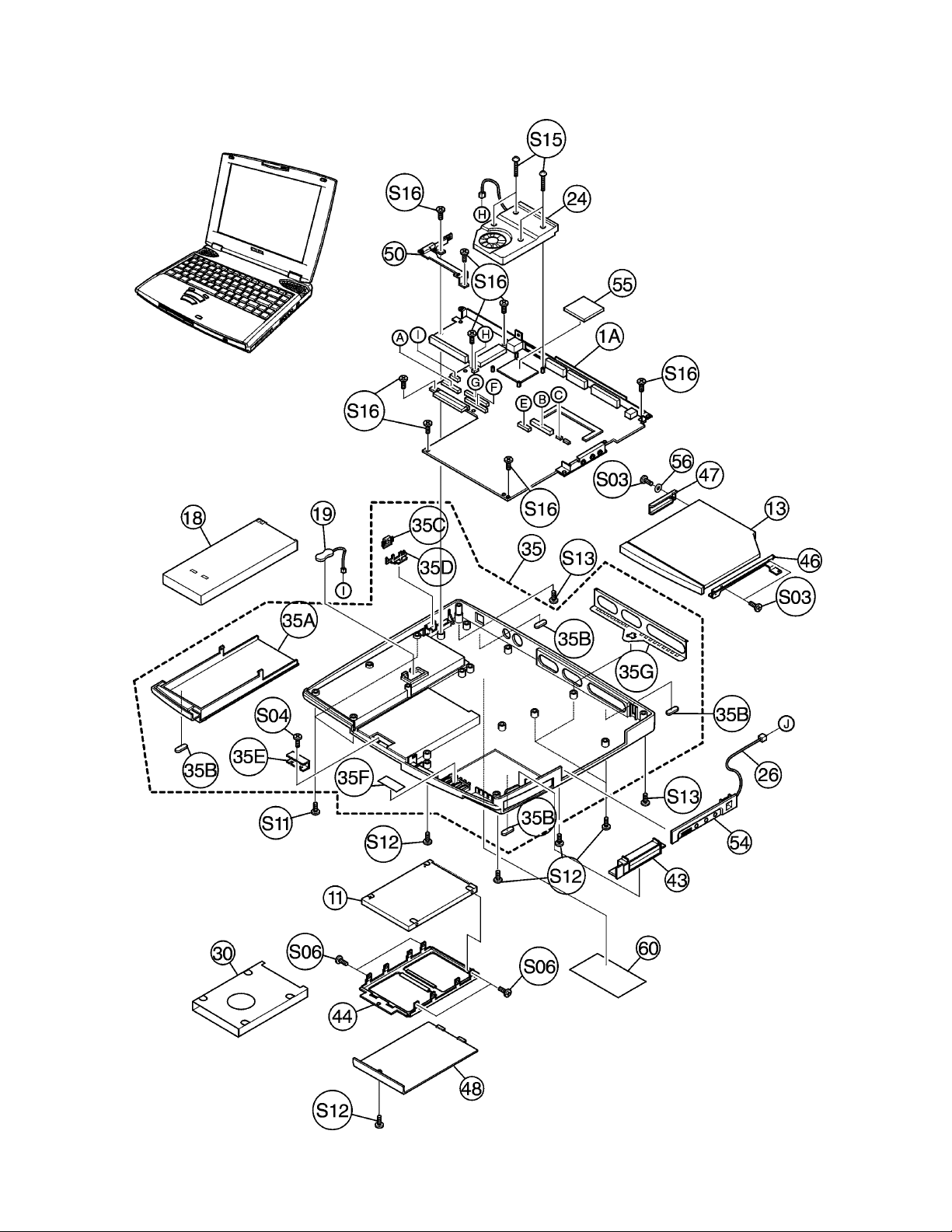
Satellite 2250CDT Exploded Upper View
Toshiba TRR
Page 2
8/00, Satellite
Page 3

Satellite 2250CDT Exploded Lower View
Toshiba TRR
Page 3
8/00, Satellite
Page 4

Satellite 2250CDT Part Numbers
Ref. # Code Part # Description PIR Comments
Part No. C1H2 PS225U-N91J08 2250CDT/6.0 (W98) Sat. 2250CDT/6.0 (Windows 98SE)
Part No. C1H2 PS225U-N91J08B 2250CDT/6.0 (W98) B-STK Sat. 2250CDT/6.0 (Windows 98SE)Remf.
OP01 C1H2 KTT-SO100/32 “Mem. Mod., 32MB SDRAM” Kingston 32MB SDRAM Mem. Mod.
OP01-A C1H2 KTT-SO100/64 “Mem. Mod., 64MB SDRAM” Kingston 64MB SDRAM Mem. Mod.
OP01-B C1H2 KTT-SO100/128 “Mem. Mod.,128MB SDRAM” Kingston 128MB SDRAM Mem. Mod.
OP02 C1H2 PA2450U Univ. AC ADAPTER “Input: 100-240VAC 0.95-0.55A 50/60HZ, Output:15VDC 3A”
OP03 C1H2 PA2487URG MAIN Batt. (4000MAH) “Lithium-Ion, 10.8VDC, 4,000mAh with recycle label”
OP04 C1H2 PA2488U Batt. CHARGER (MAIN)
S01 C1H2 P000283220 “T SCREW, M2.5X4”
S02 C1H2 P000283230 “T SCREW, M2X4”
S03 C1H2 P000215140 SCREW M2X3C
S04 C1H2 P000261210 GRIP SCREW M2.5X4BN
S05 C1H2 P000233430 SCREW M2.5X6Z
S06 C1H2 P000254870 GRIP SCREW M3X4Z
S07 C1H2 P000227770 GRIP SCREW M2.5X2.6B
S09 C1H2 P000207950 SCREW M2X4Z
S10 C1H2 P000283240 “T GRIP SCREW, M2X4BN”
S11 C1H2 P000261220 GRIP SCREW M2.5X6BN
S12 C1H2 P000283250 “GRIP SCREW, M2.5X8BN”
S13 C1H2 P000267150 “GRIP SCREW, M2.5X20B”
S15 C1H2 P000211090 “GRIP SCREW, M2X14Z”
S16 C1H2 P000300290 “T SCREW, M2.5X6”
1 C1H2 P000305660 PCB FGXSB1 “Sys. Board w/CPU, B36086111224”
3 C1H2 P000293020 PCB FGXMD2 “Modem Board, B36085571012”
7 C1H2 P000290580 COLOR LCD Mod. “Sharp, 12.1”” SVGA TFT, VF2037P01"
7A C1H2 P000296780 FL TUBE
7B C1H2 P000296790 “SCREW, M2X3.5”
7C C1H2 P000296800 “SCREW, M2X5”
7D C1H2 P000296810 “SCREW, M2X2.5”
7E C1H2 P000296820 INSULATOR SHEET
7F C1H2 P000296830 TAPE
9 C1H2 P000258360 COLOR LCD Mod. CEH “Tosh. (DTI) LTM12C283, 12.1”” SVGA TFT, VF2006P01"
9A C1H2 P000261100 FL TUBE SET
10 C1H2 P000257540 FL INVERTER UA0392P06
11 C1H2 P000285590 HDD UNIT (6.0GB) “Tosh. MK6014MAP, HDD2144G”
11-1 C1H2 P000285600 HDD UNIT (6.0GB) CEH “IBM DARA-206000, ZA2193P01”
11-2 C1H2 P000296010 HDD UNIT (6.0GB) “Fujitsu MHK2060AT, ZA2207P01”
12 C1H2 P000293030 FDD 3.5 INCH “Teac FD-005HG-1739, ZA1209P08”
12-1 C1H2 P000301450 FDD 3.5 INCH X1DE-11A
13 C1H2 P000282700 CD-ROM DRIVE “CD-224E-B32,X24”
14 C1H2 P000279550 Kybd UNIT UE2010P02
14-A C1H2 UE2010P01KB-SP Kybd UNIT (SPANISH) “Spanish style keyboard for Latin American units, UE2010P01”
15 C1H2 P000297910 STICK CAP SET
16 C1H2 P000300110 IPS HARNESS IPS Switch Board
17 C1H2 P000300120 LED HARNESS LED Board
18 C1H2 PA2487URG MAIN Batt. (4000MAH) “Lithium-Ion, 10.8VDC, 4,000mAh with recycle label”
19 C1H2 P000268840 NI-MH Batt. “RTC Batt. (small), 2.4VDC, 15mAh P710035009115”
20 C1H2 PA2450U Univ. AC ADAPTER “Input: 100-240VAC 0.95-0.55A 50/60HZ, Output:15VDC 3A”
24 C1H2 P000300130 COOLING FAN
25 C1H2 P000282810 1MM PITCH CARD FDD Flexible Cable
25-A C1H2 P000301460 1MM PITCH CARD CDA FDD Flex Cable
26 C1H2 P000282820 MODULAR JACK HARNESS “RJ11 Modem Jack, For units with an Internal Modem”
27 C1H2 P000182200 AC CORD SET
29 C1H2 P000220300 MODULAR CABLE Modem Cable
30 C1H2 P000301470 HDD INSULATOR
35 C1H2 P000306350 BASE Assy
35A C1H2 P000297400 Batt. CASE Assy Batt. Cover
35B C1H2 P000258980 BOTTOM CUSHION
35C C1H2 P000283040 POWER SWITCH BUTTON
35D C1H2 P000283050 POWER SWITCH LOCK
35E C1H2 P000283060 HDD COVER BRACKET
35F C1H2 P000283070 SHADE SHEET
35G C1H2 P000307050 DSUB EARTH SPRING
40 C1H2 P000300100 COVER Assy Top Cover and Display Cover Assy
40A C1H2 P000300160 COVER SUB Assy Top Cover Assy
40AA C1H2 P000300170 SENSOR STICK Sensor Pin (Display Sensor Pin)
40AD C1H2 P000300180 PANEL SWITCH SPRING Sensor Pin Brace
40AE C1H2 P000284310 Kybd SHIELD GASKET
40B C1H2 P000297440 LCD COVER Assy
Toshiba TRR
Page 4
8/00, Satellite
Page 5

Satellite 2250CDT Part Numbers, (cont.)
Ref. # Code Part # Description PIR Comments
40BA C1H2 P000297450 LCD LATCH Assy
40C C1H2 P000283140 “BRACKET HINGE, LEFT”
40D C1H2 P000283150 “BRACKET HINGE, RIGHT”
40E C1H2 P000300210 LCD HARNESS Display Cable
40F C1H2 P000283170 HINGE COVER
40G C1H2 P000283180 IPS SWITCH BUTTON
40I C1H2 P000283200 REINFORCED PLATE
40J C1H2 P000300240 CABLE HOLDER
40K C1H2 P000283210 LCD GUARD INSULATOR
40L C1H2 P000300220 SPEAKER
40M C1H2 P000300230 SPEAKER HOLDER Speaker Brace
40N C1H2 P000276820 SPEAKER CUSHION
41 C1H2 P000297550 LCD MASK Assy “Display Mask, Bezel”
41A C1H2 P000266750 LCD CUSHION
41B C1H2 P000257820 Tosh. BADGE
43 C1H2 P000300280 SHUTTER Assy PC Slot Cover
44 C1H2 P000282860 HDD BRACKET
45 C1H2 P000288960 FDD BRACKET FDD Case
46 C1H2 P000300140 “CD-ROM BRACKET, RIGHT” “Right Side Brace, CD-ROM”
47 C1H2 P000300150 “CD-ROM BRACKET, LEFT” “Left Side Brace, CD-ROM”
48 C1H2 P000297560 HDD COVER
49 C1H2 P000301430 Kybd HOLDER Kybd Brace
50 C1H2 P000300270 Batt. Conn. ASSY
51 C1H2 P000282930 MASK SEAL (W)
52 C1H2 P000282940 BLIND SEAL
53 C1H2 P000282950 MASK CABLE INSULATOR
54 C1H2 P000282960 MODEM SIDE COVER Conn. Panel
54-A C1H2 P000283330 SIDE COVER
55 C1H2 P000284730 HEAT CONDUCTOR SHEET
56 C1H2 P000300300 CD-ROM SPACER
57 C1H2 P000301490 LED LABEL
58 C1H2 P000301500 FDD INSULATOR
Toshiba TRR
Page 5
8/00, Satellite
Page 6

Satellite 2250XCDS Exploded Upper View
Toshiba TRR
Page 6
8/00, Satellite
Page 7
Satellite 2250XCDS Exploded Lower View
Toshiba TRR
Page 7
8/00, Satellite
Page 8

Satellite 2250XCDS Part Numbers
Ref. # Code Part # Description PIR Comments
Part No. C1H1 PS225U-M91J08 2250XCDS/6.0 (W98) Sat. 2250XCDS/6.0 (Windows 98)
Part No. C1H1 PS225U-M91J08B 2250XCDS/6.0 (W98) B-STK Sat. 2250XCDS/6.0 (Windows 98) Remf.
OP01 C1H1 KTT-SO100/32 “Mem. Mod., 32MB SDRAM” Kingston 32MB SDRAM Mem. Mod.
OP01-A C1H1 KTT-SO100/64 “Mem. Mod., 64MB SDRAM” Kingston 64MB SDRAM Mem. Mod.
OP01-B C1H1 KTT-SO100/128 “Mem. Mod.,128MB SDRAM” Kingston 128MB SDRAM Mem. Mod.
OP02 C1H1 PA2450U Univ. AC ADAPTER “Input: 100-240VAC 0.95-0.55A 50/60HZ, Output:15VDC 3A”
OP03 C1H1 PA2487URG MAIN Batt. (4000MAH) “Lithium-Ion, 10.8VDC, 4,000mAh with recycle label”
OP04 C1H1 PA2488U Batt. CHARGER (MAIN)
S01 C1H1 P000283220 “T SCREW, M2.5X4”
S02 C1H1 P000283230 “T SCREW, M2X4”
S03 C1H1 P000215140 SCREW M2X3C
S04 C1H1 P000261210 GRIP SCREW M2.5X4BN
S05 C1H1 P000233430 SCREW M2.5X6Z
S06 C1H1 P000254870 GRIP SCREW M3X4Z
S07 C1H1 P000227770 GRIP SCREW M2.5X2.6B
S09 C1H1 P000207950 SCREW M2X4Z
S10 C1H1 P000283240 “T GRIP SCREW, M2X4BN”
S11 C1H1 P000261220 GRIP SCREW M2.5X6BN
S12 C1H1 P000283250 “GRIP SCREW, M2.5X8BN”
S13 C1H1 P000267150 “GRIP SCREW, M2.5X20B”
S15 C1H1 P000211090 “GRIP SCREW, M2X14Z”
S16 C1H1 P000300290 “T SCREW, M2.5X6”
1A C1H1 P000305630 PCB FGXSB1 “Sys./Pwr Sply Board w/CPU, B36086111231”
1B C1H1 P000305640 PCB FGXVM1 “Display Contrast Board, B36086141238”
3 C1H1 P000293020 PCB FGXMD2 “Modem Board, B36085571012”
9 C1H1 P000268820 COLOR LCD Mod. “Sharp LM130SS1T579, 13.0”” SVGA DSTN, VF2017P01"
9A C1H1 P000270540 FL TUBE
9B C1H1 P000270550 SCREW
9C C1H1 P000270560 PET TAPE
10 C1H1 P000236350 FL INVERTER UA0392P05
11 C1H1 P000285590 HDD UNIT (6.0GB) “Tosh. MK6014MAP, HDD2144G”
11-1 C1H1 P000285600 HDD UNIT (6.0GB) CEE “IBM DARA-206000, ZA2193P01”
11-2 C1H1 P000296010 HDD UNIT (6.0GB) “Fujitsu MHK2060AT, ZA2207P01”
12 C1H1 P000293030 FDD 3.5 INCH “Teac FD-005HG-1739, ZA1209P08”
12-1 C1H1 P000301450 FDD 3.5 INCH X1DE-11A
13 C1H1 P000282700 CD-ROM DRIVE “CD-224E-B32,X24”
14 C1H1 P000279550 Kybd UNIT UE2010P02
14-A C1H1 UE2010P01KB-SP Kybd UNIT (SPANISH) “Spanish style keyboard for Latin American units, UE2010P01”
15 C1H1 P000297910 STICK CAP SET
16 C1H1 P000300110 IPS HARNESS IPS Switch Board
17 C1H1 P000300120 LED HARNESS LED Board
18 C1H1 PA2487URG MAIN Batt. (4000MAH) “Lithium-Ion, 10.8VDC, 4,000mAh with recycle label”
19 C1H1 P000268840 NI-MH Batt. “RTC Batt. (small), 2.4VDC, 15mAh P710035009115”
20 C1H1 PA2450U Univ. AC ADAPTER “Input: 100-240VAC 0.95-0.55A 50/60HZ, Output:15VDC 3A”
24 C1H1 P000300130 COOLING FAN
25 C1H1 P000282810 1MM PITCH CARD FDD Flexible Cable
25-A C1H1 P000301460 1MM PITCH CARD FDD Flex Cable
26 C1H1 P000282820 MODULAR JACK HARNESS “RJ11 Modem Jack, For units with an Internal Modem”
27 C1H1 P000182200 AC CORD SET
29 C1H1 P000220300 MODULAR CABLE Modem Cable
30 C1H1 P000301470 HDD INSULATOR
35 C1H1 P000306350 BASE Assy
35A C1H1 P000297400 Batt. CASE Assy Batt. Cover
35B C1H1 P000258980 BOTTOM CUSHION
35C C1H1 P000283040 POWER SWITCH BUTTON
35D C1H1 P000283050 POWER SWITCH LOCK
35E C1H1 P000283060 HDD COVER BRACKET
35F C1H1 P000283070 SHADE SHEET
35G C1H1 P000307050 DSUB EARTH SPRING
40 C1H1 P000300800 COVER Assy Top Cover and Display Cover Assy
40A C1H1 P000300160 COVER SUB Assy Top Cover Assy
40AA C1H1 P000300170 SENSOR STICK Sensor Pin (Display Sensor Pin)
40AD C1H1 P000300180 PANEL SWITCH SPRING Sensor Pin Brace
40AE C1H1 P000284310 Kybd SHIELD GASKET
40B C1H1 P000300810 LCD COVER Assy
40BA C1H1 P000297450 LCD LATCH Assy
40C C1H1 P000283910 “BRACKET HINGE, LEFT”
40D C1H1 P000283920 “BRACKET HINGE, RIGHT”
40E C1H1 P000300840 LCD HARNESS Display Cable
Toshiba TRR
Page 8
8/00, Satellite
Page 9

Satellite 2250XCDS Part Numbers, (cont.)
Ref. # Code Part # Description PIR Comments
40F C1H1 P000283170 HINGE COVER
40G C1H1 P000283180 IPS SWITCH BUTTON
40I C1H1 P000283200 REINFORCED PLATE
40J C1H1 P000300240 CABLE HOLDER
40K C1H1 P000283210 LCD GUARD INSULATOR
40L C1H1 P000300220 SPEAKER
40M C1H1 P000300230 SPEAKER HOLDER Speaker Brace
40N C1H1 P000276820 SPEAKER CUSHION
41 C1H1 P000300850 LCD MASK Assy
41A C1H1 P000266750 LCD CUSHION
41B C1H1 P000257820 Tosh. BADGE
43 C1H1 P000300280 SHUTTER Assy PC Slot Cover
44 C1H1 P000282860 HDD BRACKET
45 C1H1 P000288960 FDD BRACKET FDD Case
46 C1H1 P000300140 “CD-ROM BRACKET, RIGHT” “Right Side Brace, CD-ROM”
47 C1H1 P000300150 “CD-ROM BRACKET, LEFT” “Left Side Brace, CD-ROM”
48 C1H1 P000297560 HDD COVER
49 C1H1 P000301430 Kybd HOLDER Kybd Brace
50 C1H1 P000300270 Batt. Conn. ASSY
51 C1H1 P000282930 MASK SEAL (W)
52 C1H1 P000282940 BLIND SEAL
53 C1H1 P000282950 MASK CABLE INSULATOR
54 C1H1 P000282960 MODEM SIDE COVER Conn. Panel
55 C1H1 P000285610 HEAT CONDUCTIVE SHEET
56 C1H1 P000300300 CD-ROM SPACER
57 C1H1 P000301490 LED LABEL
58 C1H1 P000301500 FDD INSULATOR
Toshiba TRR
Page 9
8/00, Satellite
Page 10
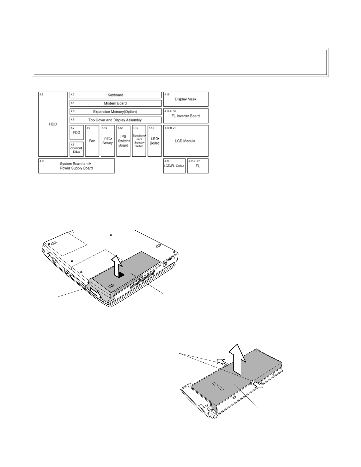
Satellite 2250CDT / 2250XCDS Disassembly Overview
The information offered in this section is an overview of the Maintenance Manual, Chapter 4, Replacement
Procedures. If you have any questions or concerns regarding the proper procedure please refer to the Maintenance Manual through the Toshiba Service and Support Website
before
you proceed.
This section explains how to disassemble the
computer and replace Field Replaceable Units
(FRUs). It may not be necessary to remove all
the FRUs in order to replace one. The chart on
the left is a guide to which FRUs need to be
removed in order to remove others.
Always start by removing the battery pack, next,
optional items such as the optional PC Card,
then follow the line on the chart to determine
which FRU you must remove next in order to
repair the one you think is causing the computer
to operate inproperly.
Battery latch
To remove the battery pack, follow the steps
below.
1. Turn the computer upside down.
2. Slide the battery latch to the right to
release it, then pull the battery cover
slightly forward and lift it out.
3. Lay the battery cover upside down.
Push the latches to the outside and lift
out the battery pack.
Battery cover
î
Latch
Toshiba TRR
Page 10
Battery pack
8/00, Satellite
Page 11

Satellite 2250CDT / 2250XCDS Disassembly Overview, (cont.)
PC Card Slot
PC Card
Eject button
M2.5 × 8 black screw
HDD cover
To remove the PC Card, follow the steps
below.
1. Pull out the eject button next to the
PC Card and press the button to
pop the card out slightly.
2. Grasp the PC Card and remove it.
CAUTION: When handling the HDD, do not
press the top surface as shown by the arrow.
Hold it by the sides.
To remove the HDD, follow the steps below.
1. Turn the computer upside down.
2. Remove one M2.5x8 black screw
and lift off the HDD cover.
3. Slide the HDD forward to disconnect
from PJ9 on the system board.
4. Lift off the HDD.
5. Remove four M3x4 flat-head
screws from the HDD bracket and
separate the bracket from the HDD.
M3 × 4 flat-head screw
HDD
î
HDD
í
HDD bracket
M3 × 4 flat-head screw
Toshiba TRR
Page 11
8/00, Satellite
Page 12

Satellite 2250CDT / 2250XCDS Disassembly Overview, (cont.)
Display Panel
Keyboard brace
Keyboard
Latch
í
M2 × 4 screws
To remove the keyboard, follow the steps below.
1. Open the display panel.
2. Lift out the keyboard brace releasing
six latches.
3. Remove two M2x4 screws.
4. Lift the keyboard out and turn it face
down on the palm rest. Be careful not
to apply pressure to the keyboard
cable.
5. Disconnect the keyboard cable from
PJ14 on the system board and remove
the keyboard.
M2 × 4 screws
Keyboard
è
PJ701
Modem cable
Modem board
Keyboard cable
Keyboard
PJ14
To remove the modem board, follow the steps
below.
1. Remove two M2x4 screws that fastens
the modem board.
2. Lift up the front side of the modem
board, exercising care about the
connector PJ16 on the system board,
and remove the modem board.
3. Disconnect the modem cable from
PJ701 on the modem board.
Toshiba TRR
PJ700
PJ16
Page 12
8/00, Satellite
Page 13

Satellite 2250CDT / 2250XCDS Disassembly Overview, (cont.)
Display Assembly
Top cover
Latches
Modem cable
Hole
Latches
M2.5 × 6
black screws
LED cable
M2.5 × 20 black screw
í
Expansion memory
M2.5 × 8 black screws
M2.5 × 8
black screws
M2.5 × 20
black screw
M2.5 × 6 black screws
If the expansion memory is installed, remove it
before you remove the top cover and display
assembly. To remove the expansion memory,
follow the steps below.
1. Gently press out on the latches. One
end of the expansion memory will pop
up.
2. Grasp the expansion memory and pull
it out.
CAUTION: Do not touch the connectors on the
expansion memory or on the computer. Debris on
the connectors may cause memory access
problems.
To remove the top cover and display assembly,
follow the steps below.
1. Turn the computer upside down and
remove the following thirteen screws:
• Two M2.5´20 black screws
• Six M2.5´8 black screws
• Five M2.5x6 black screws (from the
battery slot and back of the computer)
2. Turn the computer right side up and
open the display.
3. Disconnect the following four cables:
• LCD/FL cable from PJ2
• IPS switch cable from PJ13
• Speaker cable from PJ19
• LED cable from PJ24
4. Remove the seal on the front of the top
cover to expose one screw securing the
top cover.
5. Remove one M2x4 black screw and
three M2.5x6 screws securing the top
cover.
6. Lift the back side of the top cover and
display assembly 1 or 2 cm. Move the
top cover to the right and lift up further
to release five latches. Be careful not
to catch the modem cable on the top
cover.
PJ24
M2.5 × 6 screws
Mask cable insulator
LCD/FL cable
PJ2
Toshiba TRR
Speaker cable
PJ19
Seal
M2 × 4 black screw
IPS switch cable
PJ13
è
Page 13
8/00, Satellite
Page 14

Satellite 2250CDT / 2250XCDS Disassembly Overview, (cont.)
FDD flexible cable
PJ7
PJ10
FDD
î
M2.5 × 2.6 black screws
FDD flexible cable
To remove the FDD, follow the steps below.
1. Disconnect the FDD flexible cable from
PJ7 on the system board.
2. Remove the FDD.
3. Remove four M2.5x2.6 black screws
securing the FDD to the FDD case and
separate the FDD from its case.
4. Disconnect the FDD flexible cable from
the FDD.
FDD case
FDD
M2.5 × 2.6 black screws
Make: TeacMake: Citizen
CD-ROM Drive
î
Left side brace
To remove the CD-ROM drive, follow the steps
below.
1. Pull the CD-ROM drive slightly forward
to disconnect it from PJ10 on the
system board.
2. Lift up the CD-ROM drive and remove
it.
3. Remove two M2x3 silver screws
securing the right side brace on the
CD-ROM drive and separate the right
side brace from the CD-ROM drive.
4. Remove one M2x 3 silver screw
securing the left side brace on the CD-
ROM drive and separate the left side
brace from the CD-ROM drive.
M2 × 3 silver screw
CD-ROM drive
Right side brace
M2 × 3 silver screws
Toshiba TRR
Page 14
8/00, Satellite
Page 15

Satellite 2250CDT / 2250XCDS Disassembly Overview, (cont.)
Fan cable
PJ6
RTC battery cable
PJ12
Tape
Screws
Fan
To remove the fan, follow the steps below.
1. Remove four screws securing the fan,
and remove the fan.
2. Disconnect the fan cable from PJ6 on
the system board.
WARNING: If you replace the RTC battery, be
sure to use only batteries recommended by
Toshiba. Installation of the wrong battery can
cause the battery to explode or otherwise cause
damage.
To remove the RTC battery, follow the steps
below.
1. Remove the tape covering the RTC
battery.
2. Disconnect the RTC battery cable from
PJ12 on the system board.
3. Lift out the RTC battery.
Latches
Toshiba TRR
RTC battery
Modem jack
Page 15
To remove the system board and power supply
board, follow the steps below.
1. Press out the latches and lift off the
modem jack.
î
Images / text continued on the next page
8/00, Satellite
Page 16

Satellite 2250CDT / 2250XCDS Disassembly Overview, (cont.)
Plastic
switch cover
Latches
í
Connector panel
To remove the system board and power supply
board, continued.
2. Release the latches and remove the
connector panel.
3. Remove eight M2.5x6 flat-head
screws securing the system board and
power supply board.
4. Lift up the plastic switch cover.
5. Rotate the system board and power
supply board from the front side and
pull them out exercising care not to
catch the eject button of the PC Card
Slot on the bottom cover. Take out the
PC Card Slot cover.
M2 × 4 black screws
M2.5 × 6 flat-head screws
î
System board
CPU
Power supply board
PC Card Slot cover
IPS switch board
To remove the IPS switch board, follow the steps
below.
1. Remove three M2x4 black screws
securing the IPS switch board.
2. Lift out the IPS switch board.
Tabs
Toshiba TRR
Page 16
8/00, Satellite
Page 17

Satellite 2250CDT / 2250XCDS Disassembly Overview, (cont.)
M2.5 × 6 flat-head screws
Sensor pin brace
M2.5 × 6 flat-head screw
Speaker brace
Right speaker
Right speaker cable (red)
Tape
Sensor switch
Sensor switch cable (green)
Left speaker cable (blue)
M2.5 × 6 flat-head screws
Speaker brace
Left speaker
LCD/FL cable
Guide
LED cable
Top cover
î
Speaker
To remove the speakers and sensor switch,
follow the steps below.
1. Remove the tape securing the speaker
cables and sensor switch cable on the
back of the top cover.
2. Pull out the right speaker cable (red)
from under the sensor pin brace on the
back of the top cover.
3. Remove one M2.5x6 flat-head screw
securing each speaker brace and
remove the speaker braces.
4. Remove one M2.5x6 flat-head screw
securing the sensor switch.
5. Pull out the speaker cables and
sensor switch cable from the hole on
the back of the top cover.
6. Pull out the LCD/FL cable and LED
cable from their guide on the back of
the top cover.
7. Remove the speakers and sensor
switch.
Speaker cushion
Left speaker
Sensor switch
Guide
LCD/FL cable
Guide
LED cable
Latches
LED board
LCD/FL cable
Guide
LED cable
Top cover
Right speaker
Top cover
Hole
Speaker cables and
Sensor cable
To remove the LED board, follow the steps below.
1. Pull out the LED cable from the guide
on the back of the top cover.
2. Lift up the LED board from the side
where the LED cable is connected, so
that it clears a pin on the back of the
top cover.
3. Slide the LED board in the direction of
the LED cable to release two latches.
4. Lift up the LED board to remove it.
Toshiba TRR
Page 17
8/00, Satellite
Page 18

Satellite 2250CDT / 2250XCDS Disassembly Overview, (cont.)
Mask seals
Display mask
M2.5 × 6 screws
To remove the display mask, follow the steps
below.
12.1” model: Figures 4-29 and 4-31
13.0” model: Figures 4-30 and 4-32
1. Remove two mask seals at the hinges
to expose two screws securing the
display mask.
2. Remove two M2.5x6 screws that were
covered by the mask seals.
3. A total of 25 snaps secure the display
mask. Carefully insert your fingers
between the mask and the LCD panel
and pry open the snaps. Start with the
seven snaps at the bottom of the
display mask.
4. Continue unsnapping the display mask
along the sides (five snaps on each
side), and the top (eight snaps).
î
Mask seals
Display mask
Display mask
Toshiba TRR
Snap
Hinges
í
Page 18
î
Display mask
Snap
M2.5 × 6 screws
Hinges
8/00, Satellite
Page 19

Satellite 2250CDT / 2250XCDS Disassembly Overview, (cont.)
HV cable
CN2
CN1
FL cable
FL cable
CN1
Tape
M2.5 × 6 screws
FL inverter board
M2.5 × 6 screws
CN2
HV cable
To remove the FL inverter board (12.1” DSTN),
follow the steps below.
1. Remove the tape covering the up side
of the FL inverter board.
2. Remove the two M2.5x6 screws
securing the FL inverter board.
3. Carefully lift up the FL inverter board
and disconnect the FL cable from CN1
and the HV cable from CN2.
To remove the FL inverter board (13.0” DSTN),
follow the steps below.
1. Remove the insulator covering the right
side of the FL inverter board.
2. Remove the two M2.5x6 screws
securing the FL inverter board.
3. Carefully lift up the FL inverter board
and disconnect the FL cable from CN1
and the HV cable from CN2.
Toshiba TRR
DSTN FL inverter board
Glass tape
Insulator
HV cable
CN2
M2 × 4 screw
FL inverter board
CN1
FL cable
Glass tape
Page 19
To remove the FL inverter board (12.1” TFT),
follow the steps below.
1. Remove two strips of tape securing the
HV cable and FL cable.
2. Remove one M2x4 screw securing the
FL inverter board.
3. Carefully lift up the FL inverter board
and disconnect the FL cable from CN1
and the HV cable from CN2.
8/00, Satellite
Page 20

Satellite 2250CDT / 2250XCDS Disassembly Overview, (cont.)
M2.5 × 6 screw
Contrast board
Contrast board cable
Tapes
M2.5 × 6 screw
LCD cable
LCD Module
M2.5 × 6 screw
î
To remove the LCD module and contrast board
(12.1” DSTN), follow the steps below.
1. Remove four M2.5x6 screws securing
the LCD module.
2. Rotate the LCD module from the right
to the left out of the LCD cover. Be
careful not to apply pressure to the LCD
cable.
3. Disconnect the LCD cable from the
connector on the side of the LCD
module.
4. Remove two strips of tape securing the
contrast board cable on the back of
the LCD cover.
5. Remove one M2.5x6 screw securing
the contrast board.
6. Lift out the contrast board and disconnect the contrast board cable from the
board.
M2.5 × 6 screws
LCD cable
LCD module
î
M2.5 × 6 screws
To remove the LCD module and contrast board
(13.0” DSTN), follow the steps below.
1. Remove four M2.5x6 screws securing
the LCD module.
2. Rotate the LCD module from the right
to the left out of the LCD cover. Be
careful not to apply pressure to the LCD
cable.
3. Disconnect the LCD cable from the
connector on the back of the LCD
module.
4. Remove two strips of tape securing the
contrast board cable on the back of
the LCD cover.
5. Remove one M2.5x6 screw securing
the contrast board.
6. Lift out the contrast board and disconnect the contrast board cable from the
board.
M2.5 × 6 screw
Contrast board
Toshiba TRR
Tapes
Page 20
Contrast board cable
8/00, Satellite
Page 21

Satellite 2250CDT / 2250XCDS Disassembly Overview, (cont.)
M2.5 × 6 screws
M2.5 × 6 screws
LCD module
LCD cable
Hinge cover
To remove the LCD module (12.1” TFT), follow
the steps below.
1. Remove four M2.5x6 screws securing
the LCD module.
2. Rotate the LCD module from the right
to the left out of the LCD cover. Be
careful not to apply pressure to the LCD
cable.
3. Disconnect the LCD cable from the
connector on the back of the LCD
module.
To remove the LCD/FL cable(TFT) or LCD/FL/
Contrast cable(DSTN), follow the steps below.
1. Release two latches on the left hinge
cover and remove it.
2. Remove some strips of tape securing
the LCD/FL(/Contrast) cable as below:
• 12.1” DSTN: one cable holder and
three strips of tape
• 13.0” DSTN: one cable holder
• 12.1” TFT: one cable holder and three
strips of tape
LCD cable
Toshiba TRR
Cable holder
í
Tapes
LCD cover
Contrast cable
FL cable
è
LCD cable
Cable holder
Page 21
LCD cover
Contrast cable
FL cable
î
Images / text continued on the next page
8/00, Satellite
Page 22

Satellite 2250CDT / 2250XCDS Disassembly Overview, (cont.)
LCD cover
LCD cable FL cable
Cable holder
Tapes
î
M2.5 × 4 flat-head screws
M2.5 × 4 flat-head screws
Chassis
Screw
Screw
Screw
(2230 CDS only)
Cable brace
LCD/FL(/Contrast) cable
Screw
LCD module
Tab
Screw
Ground cable
(2230 CDS only)
To remove the LCD/FL cable(TFT) or LCD/FL/
Contrast cable(DSTN), continued.
3. Remove one M2.5x4 flat-head screw
securing the cable brace on the back of
the top cover.
4. Remove one M2.5x4 flat-head screw
securing the ground cable on the back
of the top cover. (2230 CDS only)
5. If necessary, remove one M2.5x6 flat-
head screw securing the ground cable
and left speaker brace.
6. Pull out the LCD/FL(/Contrast) cable
from the guide and from the gasket
case on the back of the top cover.
7. Pull out the LCD/FL(/Contrast) cable
from the hole at the hinge, and remove
it.
Guide
Gasket
Gasket case
Hole
To remove the DSTN FL (Model 12.1 SHARP),
follow the steps below.
1. Fold out twelve tabs on the sides of the
LCD module along the chassis.
2. Remove five screws securing the back
plate to the LCD module.
3. Remove the back plate from the LCD
module.
4. Remove tape securing the FL cable to
the chassis of the LCD module and pull
out the CCFT cable.
5. Open the CCFT reflector sheet covering
the FL and lift up the FL.
Screw hole
Screws
PET tape 3
Toshiba TRR
CCFT cable
ê
Hole
Screws
Back plate
LCD module
Hole
è
Page 22
CCFT reflecter sheet
CCFT unit
Hooks
Chassis
Lead cable
8/00, Satellite
Page 23

Satellite 2250CDT / 2250XCDS Disassembly Overview, (cont.)
Tongue
Lead cable (yellow)
1st tongue
Chassis
HV cable (blue)
í
Hooks
To install the DSTN FL (Model 12.1 SHARP),
follow the steps below.
1. Seat a new FL in the FL slot along the
groove and lay the lamp reflector sheet
in place. Make sure that the HV cable
is completely laid under five tongues in
the groove along the chassis, and under
two hooks at the chassis right corner.
2. Adhere tape to the chassis rib first and
fold it to the side of the chassis.
3. Seat the back plate on the LCD module
and align the pins on the chassis with
holes in the back plate.
Make sure that the HV cable is not
pinched by the back plate.
4. Secure the back plate with five screws.
5. Fold back twelve tabs along the chassis
on the side of the LCD module.
Screws
16 15 14 13 12 11
17
18
19
20
12 3 4 5 6
Tab
í
Back plate
Screws
Bezel
è
To remove the DSTN FL (Model 13.0 SHARP),
follow the steps below.
10
9
8
7
1. Fold out twenty tabs on the sides of the
LCD module along the chassis.
2. Remove six screws securing the back
plate to the LCD module.
3. Remove the back plate off the LCD
module.
4. Remove tape securing the FL cable to
the chassis of the LCD module.
5. Open the lamp reflector sheet covering
the FL and lift up the FL.
Tape
FL cable
Lamp reflector sheet
DSTN LCD module
Toshiba TRR
Page 23
8/00, Satellite
Page 24

Satellite 2250CDT / 2250XCDS Disassembly Overview, (cont.)
HV cable (white) HV cable (pink)
Tape
Chassis groove
Chassis hooks
Chassis rib
To install the DSTN FL (Model 13.0 SHARP),
follow the steps below.
1. Seat the FL in the FL slot along the
groove and lay the lamp reflector sheet
in place. Make sure that the HV cable
is completely laid in along the groove of
the chassis, and turned at the chassis
hooks.
2. Adhere tape on the chassis rib first and
fold it to the side of the chassis.
3. Seat the back plate on the LCD module.
4. Secure the back plate with six screws.
5. Fold back twenty tabs along the chassis
on the side of the LCD module.
í
M2.6x3.8 screws
Insulation sheets 1
Insulation sheets 2
LCD frame
LCD frame
CAUTION: Do not disassemble or modify the
FLs that are in normal operating condition.
Otherwise, there is the danger of electric
shock, and combustion of and damage to the
circuits and parts by disassembly.
To remove the TFT FL (Model 12.1 TOSHIBA),
follow the steps below.
1. Remove insulation sheets 1 and 2.
Carefully remove insulation sheet
1because it will be reused.
2. Turn the LCD module over face down
and remove the four following screws.
• Two M2.6x3.8 screws
• Two M2.6x2.8 black screws
3. Fold out the tabs on the LCD frame.
4. Remove the LCD frame, exercising
care about the latches.
Toshiba TRR
M2.6x2.8 black screws
è
Page 24
î
Images / text continued on the next page
Latches
8/00, Satellite
Page 25

Satellite 2250CDT / 2250XCDS Disassembly Overview, (cont.)
Photoconductor
M2 × 2 black screw
FPC connector
î
Cell with the PCB
To remove the TFT FL (Model 12.1 TOSHIBA),
continued.
5. Disconnect the FPC connector.
6. Remove one M2x2 black screw that
secures the PCB.
7. Remove the cell with the PCB, exercising care about the double-coated tape.
8. Remove the two prism sheets from the
backlight.
CAUTION: Do not touch the prism sheets with
a bare hand because they could be easily
damaged. Be careful not to expose them to
dirt or other foreign matter.
9. Remove the photoconductor from the
lamp reflector in the arrow direction.
10. Remove the sheet that secures the
cable.
11. While paying attention to the latches on
both sides of the FL, remove the FL
from the frame.
CAUTION: The FL is secured with doublecoated tape, and must be removed carefully
not to subject it to deformation.
í
Securing sheet
Double-coated tape
Backlight
Prism sheets
è
Backlight
í
FL
Toshiba TRR
Page 25
8/00, Satellite
Page 26

Satellite 2250CDT / 2250XCDS Disassembly Overview, (cont.)
Screws
Filament tape
Latches
Lamp cover (Remove this in step 4.)
LCD module
Protective cover
Frame (Remove this in step 3.)
Latches
Polyimide tape
Screw (Remove this in step 4.)
Screws
To remove the TFT FL (Model 12.1 SHARP
LQ121S1LH03), follow the steps below.
1. Turn the LCD module face down and
remove the protective cover, filament
tape and polyimide tape. Remove four
screws and release four latches.
2. Turn the LCD module face up and
release two latches on the side of the
frame.
3. Rotate the frame up from the side
where the latches are, and free the
frame’s U-shaped side from the edge
of the LCD module.
4. Remove one screw securing the lamp
cover, and remove the lamp cover.
Carefully, pull the lamp cable out of its
groove from the connector end. Be
careful not to contaminate or damage
the LCD panel, source TCP and gate
TCP.
5. Remove the lamp taking care not to
apply pressure to the lamp so you don’t
break it.
Frame
Latches
ê
U-shaped side
LCD module
è
Connector end
Lamp cable
í
Lamp cover
Lamp (Remove this in step 5.)
Screw
Toshiba TRR
Page 26
8/00, Satellite
Page 27

Satellite 2250CDT / 2250XCDS Disassembly Overview, (cont.)
Screws
Latches
LCD module
ê
Screws
LCD module
Latches
è
To install the TFT FL (Model 12.1 SHARP
LQ121S1LH03), follow the steps below.
1. Fit a new lamp into the white reflector
sheet. Be careful not to contaminate or
fold the white reflector sheet.
2. Route the lamp cable in its groove.
Seat the lamp cover in place and
secure it with one screw.
3. Fit the frame’s U-shaped side to the
edge of the LCD module, and rotate the
frame into place on the LCD module.
4. Secure two latches on the side of the
frame.
5. Turn the LCD module face down.
Secure four screws.
6. Secure four latches.
7. Adhere new polyimide tape as
illustrated.
8. Adhere new filament tape as illustrated.
9. Adhere new protective cover as
illustrated.
LCD module
Protective cover
Fold down.
Put the protective sheet to here.
LCD module
Fit the hole of the protective cover
with one of the board.
ç
Put the polyimide tape to this area.
A
Polyimide tape
(8 mm in width × 220±5 mm in length)
Note
Put the polyimide tape as A and B are the same width.
Do not leave the polyimide tape wrinkling or leeping.
B
ê
Do not stick the filament tape out of the chassis.
(You must not put it on the surface of the white sheet.)
Filament tape
Do not stick the filament tape out of this edge.
19 mm in width × 20 mm in length
LCD module
Toshiba TRR
Page 27
8/00, Satellite
Page 28

Satellite 2250CDT / 2250XCDS Disassembly Overview, (cont.)
M2x5 screws
M2x3.5 screws
Reinforcement tape
LCD module
Insulation tape
Latches
Frame
Latches
í
To remove the TFT FL (Model 12.1 SHARP
LQ121S1LH33), follow the steps below.
1. Turn the LCD module face down and
remove the insulation tape and
reinforcement tape.
2. Remove two M2x3.5 screws and two
M2x5 screws from LCD module and
release four latches.
3. Turn the LCD module face up and
release four latches on the side of the
frame.
4. Rotate the frame up from the side
where the latches are, and free the
frame’s U-shaped side from the edge
of the LCD module.
5. Turn the LCD module face down and
remove two M2x2.5 screws securing
the back cover.
6. Unfasten the lamp ground cable from
the case and remove the back cover.
7. Unfasten the lamp power cable and
remove the lamp housing.
8. Remove the fluorescent lamp taking
care not to break it.
Latch
Latch
Latch
Latch
Frame
Lamp housing
LCD module
î
U-shaped side
Pull out the lamp housing
in the direction by the arrow.
LCD module
Frame
LCD module
ê
M2x2.5 screws
Back cover
Fluorescent lamp
Toshiba TRR
ç
Page 28
Lamp housing
8/00, Satellite
Page 29

Satellite 2250CDT / 2250XCDS Disassembly Overview, (cont.)
Latch
Latch
To install the TFT FL (Model 12.1 SHARP
LQ121S1LH33), follow the steps below.
CAUTION: Use only new and designated by
Toshiba insulation tape and reinforcement
tape.
Latch
M2x5 screw
LCD module
M2x3.5 screw
Latch
í
î
M2x5 screw
M2x3.5 screw
1. Fit a new fluorescent lamp into the
lamp housing. Be careful not to break
the lamp or damage the lamp hous-
ing.
2. Seat the lamp housing and route the
lamp power cable.
3. Seat the back cover in place routing
the lamp ground cable in its groove.
4. Secure the back cover with two
M2x2.5 screws.
5. Turn the LCD module face up.
6. Fit the frame’s U-shaped side to the
edge of the LCD module, and rotate
the frame into place on the LCD
module.
7. Secure the frame with the four latches
on its side.
8. Turn the LCD module face down and
secure the frame with four latches, two
on each side.
9. Fix the frame on the LCD module with
two M2x3.5 screws and two M2x5
screws. (The screw tightening torque is
0.147±0.02 [N·m].)
10. Adhere new reinforcement tape to the
LCD module as illustrated.
CAUTION:
1) Do not change the value of the volume
control on the LCD module because it was
optimized before shipping. If you change the
value, the LCD module might not meet the
specification.
Align the edge of the insulation tape with
the edge of the U-shaped side of the frame.
Insulation tape
Toshiba TRR
LCD module
Reinforcement tape
Adhere the reinforcement tape evenly
as it covers two holes on the edge of the frame.
Fold the insulation tape along the side of the frame
so that it is evenly aligned with the top edge.
Folding
Adhering the insulation tape
î
LCD module
Page 29
2) Do not leave the LCD module displaying
a fixed pattern for a long time. It can cause
images to permanently burn into the LCD.
8/00, Satellite
Page 30

Satellite 2250CDT / 2250XCDS Interrupts / Memory Map
Interrupts and Memory Map for this model are not available at the time of publication.
Toshiba TRR
Page 30
8/00, Satellite
Page 31

Satellite 2250CDT / 2250XCDS Input/Output Port Assignments
Input / Output Port Assignments for this model are not available at the time of publication.
Toshiba TRR
Page 31
8/00, Satellite
 Loading...