

Page 1
TOSHIBA
1
Page 2

TOSHIBA
2
Page 3

TOSHIBA
IMPORTANT NOTICE
The instructions contained in this manual are not intended to cover all of
the details or variations in equipment, nor to provide for every possible
contingency to be met in connection with installation, operation, or
maintenance. Should further information be desired or should particular
problems arise which are not covered sufficiently for the purchaser's
purposes, the matter should be referred to the local Toshiba sales office.
The contents of this instruction manual shall not become a part of or
modify any prior or existing agreement, commitment, or relationship. The
sales contract contains the entire obligation of Toshiba International
Corporation's UPS Division. The warranty contained in the contract
between the parties is the sole warranty of Toshiba International
Corporation's UPS Division and any statements contained herein do not
create new warranties or modify the existing warranty.
Any electrical or mechanical modifications to this equipment,
without prior written consent of Toshiba International Corporation
will void all warranties and may void UL/CUL listing. Unauthorized
modifications also can result in personal injury, death, or
destruction of the equipment.
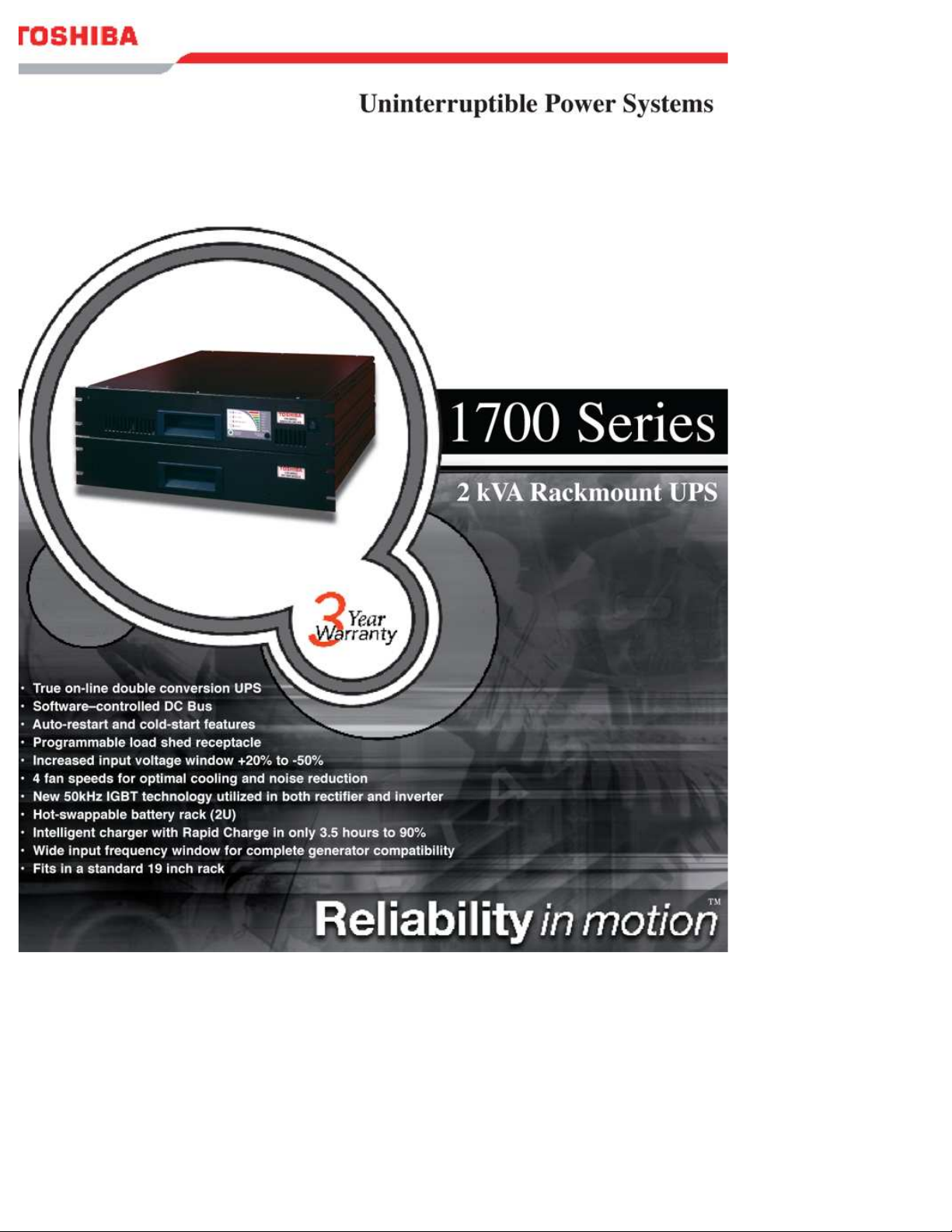
UNINTERRUPTIBLE POWER SUPPLY
If additional information or technical assistance is required beyond what
is included in this manual contact Toshiba’s marketing department by
calling toll free (800) 231-1412, by e-mail at
toshibaups@tic.toshiba.com,
or write to: Toshiba International Corporation, 13131 W. Little York
Road, Houston, TX 77041-9990.
Please complete the following information for your records and to remain
within this equipment manual:
Model Number:
Serial Number:
Date of Installation:
Inspected By:
December, 2004
Part no. 55349-001
3
Page 4

TOSHIBA
TABLE OF CONTENTS
SECTION
Disclaimer ................................................................................................3
Table of Contents ....................................................................................4
General Safety Instructions....................................................................5
Important Safety Instructions............................................................. 6-7
Inspection/Installation.............................................................................8
Inspection of the New UPS ......................................................................................... 8
Installation Precautions............................................................................................... 8
Operating Precautions ................................................................................................ 8
External Layout........................................................................................9
Electronics Module ..................................................................................................... 9
Battery Modules........................................................................................................ 10
UPS Connections ..................................................................................10
Standard Module Connections.................................................................................. 10
Operating the UPS.................................................................................11
Display Panel Layout ................................................................................................ 11
Starting the UPS System .......................................................................................... 11
Starting when AC Power is Available........................................................................ 11
Starting on DC Power ............................................................................................... 12
Stopping the UPS ..................................................................................................... 12
UPS Display Status and Operating Condition ........................................................... 13
Battery Backup Time................................................................................................. 15
Load Shed Function.................................................................................................. 15
Battery Recharge Time............................................................................................. 15
Battery Check Function............................................................................................. 15
The Function Control Button ..................................................................................... 16
Fixed Frequency Mode ............................................................................................. 16
Adding Additional Battery Modules ........................................................................... 19
Other Option Modules............................................................................................... 19
Communication Interface .....................................................................20
Remote Contacts...................................................................................................... 20
RS-232C................................................................................................................... 20
Option Card Slot ....................................................................................................... 22
Troubleshooting ....................................................................................22
Warning/Fault Modes................................................................................................ 22
Warnings .......................................................................................................... 23
Faults................................................................................................................ 25
Storage of UPS Equipment...................................................................29
Disposal.................................................................................................................... 29
Preventative Maintenance/Parts Replacement...................................30
Preventative Maintenance......................................................................................... 30
Parts Replacement ................................................................................................... 30
Appendices ............................................................................................31
A: Specifications...................................................................................................... 31
B: Fan Speed Control.............................................................................................. 32
C: System Overload Rating ..................................................................................... 33
D: Parallel Operation............................................................................................... 34
E: Bypass Undervoltage / Overvoltage.................................................................... 35
F: Unit Configuration Options .................................................................................. 36
G: Weights and Dimensions .................................................................................... 37
Warranty Policy .....................................................................................38
PAGE
4
Page 5
TOSHIBA
GENERAL SAFETY INSTRUCTIONS
Warnings in this manual appear in two different ways:
1) Danger warnings - The danger warning symbol is an exclamation mark
enclosed in a triangle that precedes the large bold letters spelling the
word "DANGER". The Danger warning symbol is used to indicate
situations, locations, and conditions that exist and can cause serious
injury or death:
DANGER
2) Caution warnings - The caution warning symbol is an exclamation mark
enclosed in a triangle that precedes the large bold letters spelling the
word "CAUTION". The Caution warning symbol is used to indicate
situations and conditions that can cause operator injury and/or
equipment damage:
CAUTION
Other warning symbols may appear along with the Danger and Caution
symbol and are used to specify special hazards. These warnings
describe particular areas where special care and/or procedures are
required in order to prevent serious injury and possible death:
1) Electrical warnings - The electrical warning symbol is a lightning bolt
mark enclosed in a triangle. The electrical warning
symbol is used to indicate high voltage locations and
conditions that may cause serious injury or death if
the proper precautions are not observed.
2) Explosion warnings - The explosion warning symbol is an explosion
mark enclosed in a triangle. The explosion warning symbol is
used to indicate locations and conditions where molten,
exploding parts may cause serious injury or death if the
proper precautions are not observed.
5
Page 6
TOSHIBA
IMPORTANT SAFETY INSTRUCTIONS
SAVE THESE INSTRUCTIONS. This manual
contains important instructions for the 1700 Series Toshiba Rackmount
UPS. These instructions should be followed during the installation and
maintenance of the UPS and its batteries.
The maximum ambient temperature in which this UPS unit should
be operated or stored is 104 °F (40 °C).
The batteries for the Toshiba 1700 Series Rackmount UPS are
housed in a self-contained battery module. This module should not
be opened under any circumstances. To replace the batteries, a
new module should be obtained from your local Toshiba
representative, or contact the Toshiba UPS marketing department
toll-free at (800) 231-1412.
When changing battery packs, be sure to use the proper model unit.
CAUTION
DANGER
CAUTION
CAUTION
CAUTION
Misuse of this equipment could result in human
injury and equipment damage. In no event will
Toshiba Corporation be responsible or liable for
either indirect or consequential damage or injury
that may result from the use of this equipment.
Do not dispose of the battery module
in a fire. The batteries inside may
explode.
Do not open or mutilate the battery module.
Released electrolyte is harmful to the eyes and
skin, and could be toxic.
This unit contains sealed lead acid batteries.
Lack of preventative maintenance could result in
batteries exploding and emitting gasses and/or
flame.
Failure to replace the battery pack in
accordance to the maintenance schedule may
cause the batteries inside to crack, possibly
releasing electrolytes from the battery, and
resulting in secondary faults such as odor,
smoke and fire.
6
Page 7
TOSHIBA
INSTRUCTIONS IMPORTANTES
CONCERNANT LA SÉCURITÉ
CONSERVER CES INSTRUCTIONS. Cette notice
contient des instructions importantes concernant la sécurit.
ATTENTION
ATTENTION
ATTENTION
Une batterie peut présenter un risque de
choc électrique, de brûlure par transfert
d’énergie.
Pour le remplacement, utiliser le même
nombre de batteries du modèle suivant.
L’élimination des batteries est
réglementée. Consulter les codes
locaux à cet effet.
7
Page 8
TOSHIBA
Inspection/Installation
Inspection of the New UPS Equipment
Upon receipt of the UPS, a careful inspection for shipping damage
should be made.
After Unpacking:
1) Check the unit for loose, broken, bent or otherwise damaged
parts. If damage has occurred during shipment, keep all original
packing materials for return to shipping agent. Warranty will not
apply to units damaged during shipment.
2) Check to see that the rated capacity and the model number
specified on the nameplate conform to the order specifications.
Installation Precautions
1) Install the unit in a well ventilated location; allow at least 10 cm
(4 inches) on all sides for air ventilation and for maintenance.
2) Install the unit in a stable, level, and upright position that is free
of vibration.
3) Install the unit where the ambient temperature is between 32°
and 104°F (0° and 40°C).
4) Do not install the UPS in areas that are subject to high humidity.
5) Do not install the UPS in a location that will cause direct sunlight
to shine on the unit.
6) Do not install the UPS in areas that are subject to contamination
such as high levels of airborne dust, metal particles, or
flammable gas.
7) Avoid installation near sources of electrical noise. Always make
sure that the unit earth ground is intact to prevent electrical
shock and to help reduce electrical noise.
8) Do not install where water or any foreign object may get inside
the UPS.
9) This UPS generates and can radiate radio-frequency energy
during operation. Although RFI noise filters are installed inside
the unit there is no guarantee that the UPS will not influence
some sensitive devices which are operating close by. If such
interference is experienced, the UPS should be installed farther
away from the affected equipment and/or powered from a
different source than that of the affected equipment.
Operating Precautions
1) The UPS should not be powered up until this entire manual has
been reviewed.
CAUTION
CAUTION
8
Page 9
TOSHIBA
2) The input power source voltage and frequency must be within
the allowable range as specified in appendix A. Voltages and
frequencies outside of the permissible tolerance range may
cause internal protection devices to activate.
3) The UPS should not be used with a load whose rated input is
greater than the rated UPS output.
4) Do not use the UPS to provide power to motors that require high
starting current or that require a long starting time such as
vacuum cleaners and machine tools (unless appropriate sizing is
done by a Toshiba applications engineer, or other qualified
personnel).
5) Do not insert metal objects or combustible materials in the unit's
ventilation slots.
6) Do not place, hang, or paste any objects on the top or on the
exterior surfaces of the UPS.
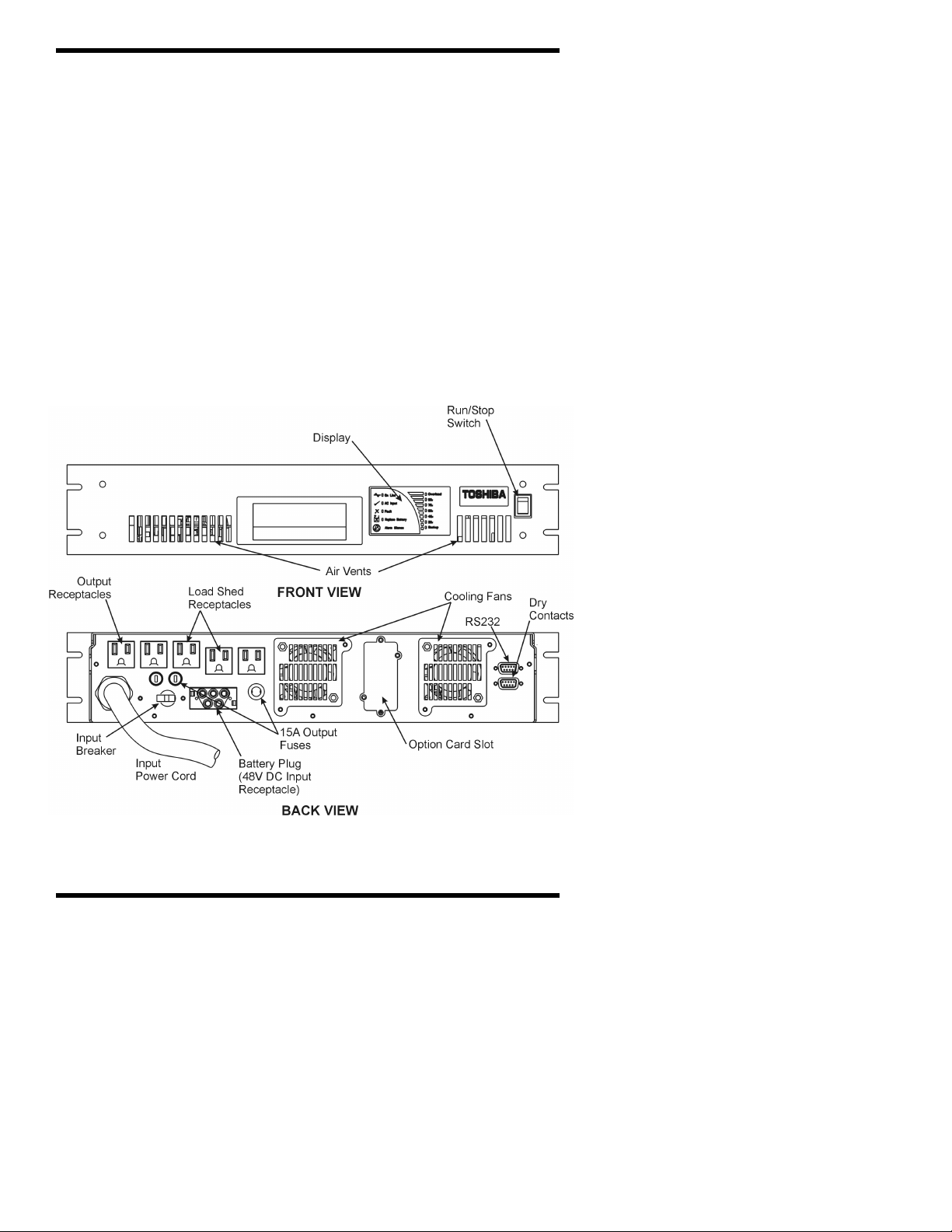
External Layout
Electronics Module
Figure 1
Electronics Module Layout
9
Page 10
TOSHIBA
Power Connections
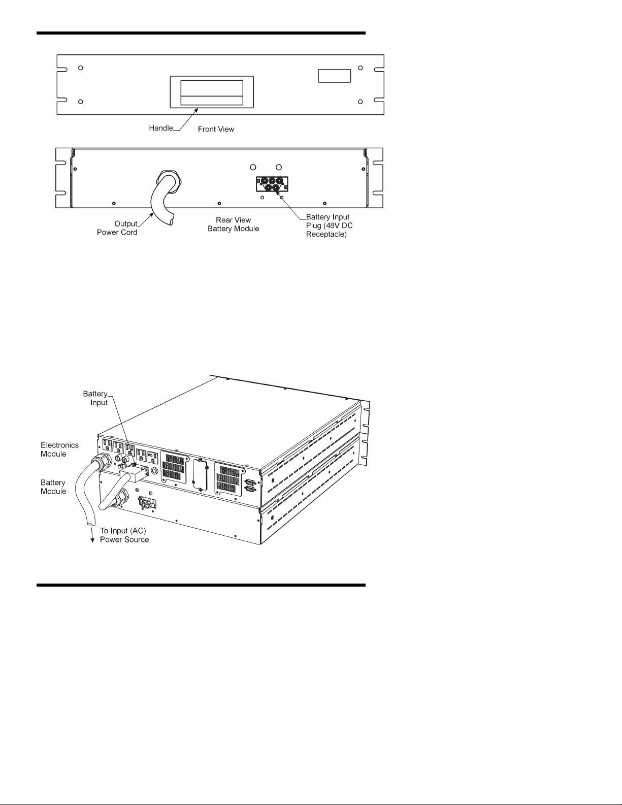
Battery Module
Figure 2
Battery Module Layout
UPS Connections
Standard Module Connections
The following illustration shows the proper assembly of the two
modules that make up the standard unit. If additional battery
modules are being installed with the standard unit see page 19.
Figure 3
10
Page 11
Operating the UPS
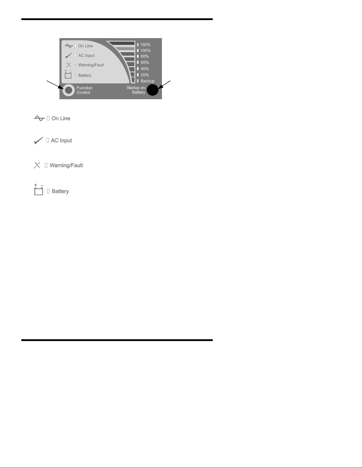
Display Panel Layout
TOSHIBA
Function
Control
Button
Startup on
Battery
Button
ON LINE (green lamp)
Lights green when the UPS’s inverter is
supplying power to the load.
AC INPUT (green lamp)
Lights green when normal AC input power
is being supplied to the UPS unit.
WARNING/FAULT (red lamp)
Lights red when the UPS unit is
experiencing an abnormal condition.
BATTERY (red lamp)
Lights red to indicate that a condition exists
that is affecting the batteries.
Starting the UPS System
Once the modules have been connected as shown in the preceding
section (UPS Connections, page 10) the UPS system is ready to be
started. There are two ways to start the system: from AC input
power (if present) or from batteries. If not already done, switch the
input breaker on (figure 1, page 9). If the “AC Input” LED is lit,
proceed on to “Starting when AC power is available”. If the LED is
not lit, there is no AC power available. If the unit is to be started
when AC power is not available proceed to “Starting on DC power.”
Starting When AC Power is Available
If the system is being started with AC input power the system is
started by switching the RUN/STOP switch to the RUN position
(RUN = I, STOP = 0). When the RUN/STOP switch is in the RUN
position both the “AC Input” and the “On Line” LEDs should be lit.
When the unit is started with AC input power it is advisable to allow
time for the batteries to fully charge before any load is connected
(see “Battery Recharge Time”, page 15).
11
Page 12

TOSHIBA
Starting on DC Power
If no AC power source is available, or if the AC input power is
outside of the allowable range for voltage or frequency, the UPS can
be started from battery power. The length of UPS operation time on
battery power depends on the number of attached battery modules
and the amount of load the UPS is supporting. To start the UPS
from battery power follow these steps:
Step 1: Make sure the RUN/STOP switch is in the STOP position. If
the UPS is being started on DC power because the AC power is out
of range, the input breaker must be in the OFF position (figure 1,
page 9).
Step 2: Press the “Startup on Battery” button. The UPS will beep
indicating that AC power is not available and the Startup on Battery
mode has been activated.
Step 3: Switch the RUN/STOP switch to the RUN position. This
must be done within 5 seconds of the Startup on Battery mode
activation for the unit to startup using batteries.
Once the unit has started, the “On Line” LED will light, indicating that
the inverter is running and power is available at the output
receptacles. If the RUN/STOP switch is not switched to the RUN
position within those 5 seconds, the unit will return to shutdown
mode.
Stopping the UPS
There are two ways of turning the UPS off: switching from on line to
bypass mode, or completely shutting down.
Option 1: The first option is to place the UPS into bypass mode.
Bypass mode means that if there is AC power available, the UPS will
route power directly from the input source to the connected loads
without any conditioning. The UPS inverter is off during this state,
but the attached loads do not lose power during the transition. To
place the UPS into bypass mode, switch the RUN/STOP switch to
the STOP position. This mode is most often used manually during
maintenance and programming operations or automatically upon the
occurrence of an internal UPS fault. (For more information
concerning bypass mode see appendix E.)
Option 2: The other option is to turn the UPS off completely. This
means that in addition to the UPS’s inverter shutting down, all power
will be stopped to any equipment attached to the UPS. To shut
the UPS down completely switch the RUN/STOP switch to the STOP
position. Then switch the input breaker off (figure 1, page 9). Once
the input breaker has been switched off, all the LEDs should turn off.
(If the RUN/STOP switch is in the RUN position when the input
breaker is switched off, the unit will switch to battery backup mode.
The unit will continue to run for as long as the available battery
reserves can support the connected loads.)
12
Page 13
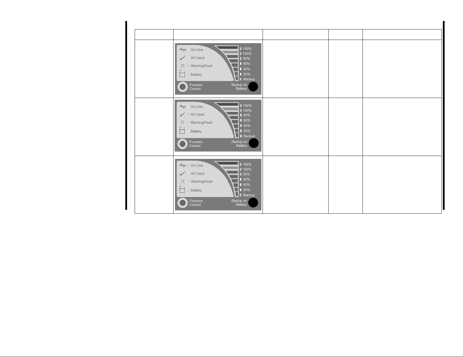
UPS Display Status and Operating Condition
Operation Mode
Display State
LED State
Alarm State
Notes
Normal
On Line .............On
AC Input............On
Alarm is
off.
20% to 100%* ...On
*see note 1.
Battery
13
Backup
On Line .............On
Battery ..............On
Backup..............On
20% to 100%* ...On
*see note 2.
Alarm will
sound for
1 second
at 10
second
The unit will return to
normal operation mode
when AC power is restored.
TOSHIBA
intervals.
Bypass
AC Input............On
20% to 100%* ...On
*see note 1.
Alarm is
off.
Battery backup is not
available.
Page 14

UPS Display Status and Operating Condition
Operation Mode
Parallel
Operation
Display State
LED State
On Line .............On
AC Input............On
Battery ..............On
20% to 100%* ...On
*see note 1.
Alarm State
Alarm will
sound for
1 second
at 10
second
intervals.
Notes
Parallel operation occurs when
input power is present, but
inadequate to fully power the
connected load. The batteries
are used to supplement the
AC input power. The UPS will
return to normal operation
when full input power returns.
All other display conditions constitute either a warning or a fault condition. These conditions are explained in the section titled “Troubleshooting”
14
(page 22) in the charts on Warnings and Faults.
Note 1: The level meter, which consists of the LEDs labeled 20% through 150%, will light according to the current amount of load connected.
As the load exceeds one level, the next level will begin to blink, increasing the blink rate as the load increases until that full percentage is
reached. For example, if the unit is loaded to 40% of maximum output power the 20% and 40% LEDs will be lit. If another small load is added
increasing the load to 45% the 60% LED will begin to blink. If a little bit more load is added so that the total load becomes 50% the 60% LED will
blink faster. This will continue until enough load is added to equal 60% of the maximum output power at which time the 60% LED will stop
blinking and light continuously.
Note 2: The level meter described in note 1 above also displays the remaining battery time when the unit is in backup mode. If the batteries are
fully charged when the unit switches to backup mode the 20% through 100% LEDs will light. As the batteries begin to discharge, the LEDs
starting from the top will blink rapidly then slowly and will then turn off as the battery time runs down. For example if the unit has been running on
battery power and there is 90% battery capacity remaining the 20% through 80% LEDs will be lit and the 100% LED will be blinking.
TOSHIBA
Page 15

TOSHIBA
Battery Backup Time
The exact amount of backup time provided will vary depending on
the UPS model being used, number of batteries, condition of the
batteries and other factors. However, the chart below gives the
times that can be expected from the standard units with batteries in
good condition. For greater backup time, an additional battery
module may be added to the standard unit. Only one additional
battery module may be added to the standard unit. For longer
runtime options contact your Toshiba sales representative or the
Toshiba marketing department at (800) 231-1412 or by e-mail at
toshibaups@tic.toshiba.com.
Table 1
Backup Time*
UPS Model
With 1 Battery Module
Full Load / Half Load
With 2 Battery Modules
Full Load / Half Load
2000 VA 13 min / 32min 32 min / 77 min
2400 VA 9 min / 26 min 30 min / 64min
* Times given are approximate and will vary depending on the age of the batteries, the
battery temperature, the number of previous discharges and the type of load.
Load Shed Function
The 1700 Series includes a load shed function. During battery
backup operation, this function allows the load connected to two of
the receptacles (figure 1, page 9) to be turned off in an effort to
conserve power for more critical loads. The battery level at which
these two receptacles will be turned off, or “shed”, can be set by the
user (see “The Function Control Button”, page 16). By default, this
feature is configured so that these two receptacles will remain on for
the full battery backup time available (no “shedding”)
Battery Recharge Time
The following table gives estimates on time required to recharge the
UPS’s batteries. The recharge time may vary depending on the
battery temperature, the age of the batteries, and other factors.
Table 2
Battery Recharge Time*
Unit With 1 Battery Module With 2 Battery Modules
2000 VA 4 ½ hours 9 hours
2400 VA 4 ½ hours 9 hours
* Recharge times are to 90% full capacity.
Fan Speed
The 1700 Series Rackmount UPS has variable speed fans. The fan
speed will vary depending on a number of factors. As the load
15
Page 16

TOSHIBA
placed on the UPS increases the fan speed will increase. The
temperature of the environment the UPS is operating in can also
cause the fan speed to increase. (For a more detailed explanation of
the variable speed fan function refer to appendix B)
Battery Check Function
During startup the UPS will perform an automatic 'Battery Check' to
detect whether a problem exists in the battery circuit. If the batteries
pass the test, the unit will start normal operation. If a problem is
detected during the test the “Warning/Fault” LED will activate. Other
LED’s may also activate. If this occurs please refer to the
“Troubleshooting” section on page 20 for a description of the
problem and possible solutions. It is important to note that when
the UPS has detected bad batteries, the battery backup mode is
disabled. The unit will continue to operate and provide clean power;
however, since there is no battery power available, the unit cannot
provide backup power if input power is lost.
The Function Control Button
The function control button is located on the display panel (see
“Display Panel Layout”, page 11). This button is used to perform
several different UPS operations, including initiating self test,
providing programming options, and silencing the alarm. A brief
description of each function follows along with a step by step guide
to accessing each function.
1) Self-Test. In order to perform a self-test the UPS must be
operating in the normal mode (see “UPS Display Status and
Operating Condition”, page 13). To initiate the self-test simply
press and hold the Function Control button until the audible
alarm sounds. The self-test performs the same battery check
described above.
2) Alarm Silence. The alarm silence feature is used to stop the
audible alarm from sounding. Any time the audible alarm is
sounding pressing the Function Control button will silence the
alarm.
3) Programming Mode. There are three programming options:
load shed, output enable/disable after input overvoltage backup,
and reset battery installed date. In order to enter the
programming mode the UPS must first be operating in Bypass
mode without faults (see “Stopping the UPS: Option 1”, page
12). Then press and hold the Function Control button. (“Press
and hold” always means to hold until the unit gives audible
feedback). The unit will give an audible feedback indicating the
unit is in programming mode. (If at anytime while the UPS is in
the programming mode there is one minute of inactivity the UPS
16
Page 17

TOSHIBA
will automatically exit the programming mode and return to
bypass operation.) What follows is a step by step guide to
navigating in the programming mode, followed by a detailed
description of each option.
A. Load Shed. The backup LED will light indicating the UPS is now
ready to make changes to the load-shed settings (see “The Load
Shed Function”, page 15 for an explanation of load shedding).
To accept this option press and hold the Function control button.
A.1 The UPS comes from the factory set so the load shed
receptacles function for the full battery backup time. The
LEDs on the right side of the display will light to indicate the
current setting for the load-shed level. For example, since
the default factory setting is for no load shed, the first time
the option is accessed no LEDs will be lit. Pressing the
button once will cause the 20% LED to light. This would
indicate that the load shed receptacles should be turned off
when there is 20% battery power remaining. Pressing the
Function Control button successive times will increase the
load shed level in 20% increments.
17
Page 18

TOSHIBA
A.2 Once the option is set to the desired level, press and hold
the Function Control button. This will save the new load
shed level setting. The UPS will indicate that the value has
been stored by blinking the LEDs. After blinking the LED for
a short time the UPS will exit the programming mode and
return to bypass operation. To return the system to normal
operation switch the RUN/STOP switch back to the RUN
position.
B. Output Enable/Disable After Input Overvoltage Backup. Press
the function control button. The unit is now ready to change the
output enable/disable after input overvoltage backup option.
This is indicated by the 150% LED turning on. This setting
determines whether the UPS will go to bypass in the case of an
input overvoltage fault. To change this setting press and hold the
function control button.
B.1 This setting is set to disable output at the factory. Pressing
the function control button causes the 100% LED to light,
indicating output has been enabled. Pressing it again will
change it back to disabled and the 100% LED will go off.
B.2 Once the option is set as desired, press and hold the
function control button to save the setting. The UPS will
indicate the setting has been saved by blinking the LED(s).
The LED(s) will continue to blink for a short time after which
the UPS will exit programming mode and return to bypass
operation. To return the system to normal operation switch
the RUN/STOP switch back to the RUN position.
C. Reset Battery Installed Date. This should be done whenever a
new battery pack is installed. Press the function control button.
The unit is now ready to reset the battery installed date. This is
indicated by the Battery LED turning on. Once this mode has
been entered press and hold the function control button to reset
the battery install date to the current date. The UPS will indicate
that the date has been reset by blinking the Battery LED for a
short time after which the UPS will return to bypass operation.
To return the system to normal operation switch the RUN/STOP
switch back to the RUN position.
18
Page 19

TOSHIBA
Fixed Frequency Mode
The 1700 Series Rackmount UPS has the option of operating in a
fixed frequency mode. Normally the UPS operates in the frequency
auto-detect mode. If a specific output frequency is required (i.e.
50Hz or 60Hz) the UPS can be set at the factory to supply the
desired frequency regardless of the input frequency (input frequency
must be within allowable limits, see Specifications on page 29). For
a unit already in use the output frequency can be set through
software. For instructions on setting the output frequency through
software please contact Toshiba at (800) 231-1412 or by e-mail at
toshibaups@tic.toshiba.com. It is important to note that when the
UPS is operating with a fixed output frequency, output is
disabled in bypass.
Adding an Additional Battery Module
Note: Only one additional battery module may be added to the
standard unit. Figure 4 shows the standard unit with one additional
battery module added. To install an additional battery module follow
these steps:
1) Make room in the rack for the additional battery module to be
placed below the other modules. Secure the new battery module
in the rack.
2) Plug the new battery module output power cord into the battery
input plug on the battery module.
.
Figure 4
Expansion Battery Module
19
Page 20

TOSHIBA
2 3 4 5 6 7 8 9
Communication Interface
Dry Contacts
The remote contacts interface is a standard feature. It is provided
through solid state relays with contacts through a DB9 male
connector located on the back of the UPS (refer to the
Communication Option User Manual for a more detailed description
of this option). The following chart shows the signals and the
connector pinout.
Pin Signal Function Logic In the UPS
1 Fault Signal
UPS stop
2
common
UPS stop signal
3
input
Normal input
4
power supply
Closed when fault
detected
Backup stop when the
level changes from Low (3 to – 15V) to High (+3 –
+15V)
Closed with normal
supply power
5 Signal common Common signal return
6 Bypass operation
Battery voltage
7
low
8 UPS operation
Power failure
9
signal
Closed during bypass
operation
Closed at voltage drop
Closed during inverter
operation
Closed at power failure
Voltage Current
48Vdc peak 100mAdc peak
DB9 Male Connector Outline
(facing connector)
30Vac rms
(42Vac peak)
70mAac rms
(100mAac peak)
RS-232C
RS-232C serial communication interface is a standard feature
provided through a DB9 female connector located on the backside of
the UPS (see “Electronics Module Layout “, page 9). This interface
allows communication between the UPS and a personal computer.
The chart on the following page shows the signals and the connector
pinout.
20
1
Page 21

TOSHIBA
Pin Signal Name Description In the UPS
1 -
2 RXD Receive data
3 TXD Transmit data
4 DTR Data terminal ready
5 GND Signal ground
6 DSR Data set ready
7 RTS Request to send
8 CTS Clear to send
9 -
(*) (**) These pins are tied together internal to the UPS. Signals
DTR, DSR, RTS, and CTS are not used.
DB9 Female Connector Outline
(facing connector)
Special notes concerning RS-232C communication
• For Toshiba UPS protocol and command structure refer to the
Communication Option User Manual
• The optional RemotEye™ SNMP interface is the recommended
method for communication with the UPS system.
• If an optional RemotEye™ SNMP interface card is installed in the
UPS only one method (SNMP or RS-232C) will function at a time.
• For a description of the cable required to connect to a Toshiba
UPS system refer to the Communication Option User Manual or
contact Toshiba’s UPS Marketing Department at (800) 231-1412 or
by e-mail at toshibaups@tic.toshiba.com.
21
Page 22

TOSHIBA
Option Card Slot
The option card slot is a standard feature. An optional network
adapter card slides into the slot which is located on the back of the
electronics module (figure 1, page 9). This optional interface allows
the UPS to be monitored across the network or from any point on the
Internet (refer to the Communication Option User Manual for a more
detailed explanation of this option).
Troubleshooting
Warnings and Faults are those abnormal conditions that can occur
and could cause the unit to stop normal operation. These conditions
are detected by the protective circuitry in the unit. The UPS
“Warning/Fault” lamp will light red when a warning or fault occurs.
"Troubleshooting" involves monitoring the LED’s on the front panel
and then interpreting the readout by using the warning and fault
mode display charts that follow. Only the state of the LED’s listed in
the chart should be considered. Other LED’s might be active;
nevertheless, only those listed under the column “LED state” should
be considered when diagnosing a warning, or fault.
Warning/Fault Modes
All warnings will cause the red “Warning/Fault” LED to flash. All
faults will cause the red “Warning/Fault” LED to light continuously.
Some warnings and most faults will cause the UPS to transfer to
bypass mode. In many cases, after the condition that caused the
fault is corrected the unit will automatically transfer back to normal
mode. For those cases where the unit does not transfer back
automatically contact your Toshiba UPS service representative at 1877-867-8773 (outside the U.S. call 713-466-0277).
22
Page 23

temperature is reduced.
Warnings
23
Warning
Low Battery
Current
Limit (Over
Current)
Ambient
Over Heat
Display State
LED State
Warning/Fault ...Flash
Backup..............Flash
Warning/Fault ...Flash
80%...................Flash
Warning/Fault ...Flash
100%.................Flash
Alarm State
Alarm will
sound for
1-second
at 5second
intervals.
Alarm will
sound for
1/2-
second at
1-second
intervals.
Alarm will
sound for
1-second
at 15second
intervals.
Description and Resolution
The batteries have less than
30% power remaining. The
warning will continue until either
the batteries become completely
exhausted or AC input power is
restored.
An output current limit warning
is typically a sign of
misapplication. The load may
not be appropriate for UPS
support. For further explanation
contact your Toshiba UPS
service representative at 1-877867-8773 (outside the U.S.
call 713-466-0277).
The temperature of the UPS
operating environment is too
high. Causes of this condition
include allowing the room
temperature to exceed 104°F
(40°C), a blocked vent or direct
sunlight on the unit. The unit will
transfer to bypass until the
TOSHIBA
Page 24

Warning (cont’d)
24
Warning
Battery
Over Heat
Input Under
Voltage
(see note 1)
Input Over
Voltage
(see note 1)
Display State
LED State
Warning/Fault ...Flash
Battery ..............Flash
Warning/Fault ...Flash
20%...................Flash
Warning/Fault ...Flash
40%...................Flash
Alarm State
Alarm will
sound for
1-second
at 15second
intervals.
Alarm will
sound for
1/2second at
10second
intervals.
Alarm will
sound for
2, 1/2second
beeps at
10second
intervals.
Description and Resolution
This warning can be caused by
the same conditions listed for
ambient overheat. Another
possible cause would be a
problem with the battery module,
which could prevent the unit
from providing backup power.
This warning will occur if the input
voltage drops below the minimum
allowable voltage. If the unit was
online when the warning occurred it will
transfer to battery backup. After the
backup the output will shutdown. If the
unit was in bypass the output will be
turned off. The unit will reinitialize the
startup sequence if input power returns
to within specified limits.
This warning will occur if the input
voltage exceeds the maximum
allowable voltage. If the unit was
online when the warning occurred it will
transfer to battery backup (see note 2).
If the unit was in bypass the output will
be turned off. The unit will return to
normal operation if input power returns
to within specified limits.
TOSHIBA
Page 25

Warnings (cont’d)
Warning
Input
Frequency
Regulation
(see note 1)
Display State
LED State
Warning/Fault ...Flash
60%...................Flash
Alarm State
Alarm will
sound for
3, 1/2second
beeps at
10-second
intervals.
25
Output
Overload
Warning/Fault ...Flash
150%.................Flash
Alarm will
sound for
1-second
at 15second
intervals.
= Flashing LED = LED lit continuously
Note 1: If any of these faults occur while the UPS is in online mode it will immediately transfer to backup mode. In this case the percentage LED’s
will be used to show the battery power status. To identify the fault that has occurred listen to the number of consecutive beeps. One beep
indicates an input undervoltage, two beeps means input overvoltage, three beeps is a frequency problem.
Note 2: Once the batteries are exhausted the unit will either shutdown the output, or switch to bypass according the selections set by the user (see
the section entitled “Programming Mode” part B on page 18).
Description and Resolution
The input frequency is outside
specified limits. If the unit was
online when the warning occurred
it will transfer to battery backup.
After the backup the output will
shutdown. If the unit was in
bypass the output will be turned
off. The unit will return to normal
operation if input frequency
returns to within specified limits.
The connected load exceeds
the UPS power rating.
Reduce the load attached to
the UPS. The unit will
automatically return to normal
operation.
TOSHIBA
Page 26

Faults
26
Fault
Replace
Battery
Battery
Shutdown
DC Bus
Over
Current
Display State
LED
Warning/Fault ...On
Battery ..............On
Warning/Fault ...On
Backup..............On
Warning/Fault ...On
20%...................On
Alarm State
Alarm will
sound for
1/2second, at
1/2second
intervals.
Continuous
alarm
Alarm will
sound for
1/2second, at
1/2second
intervals.
Description and Resolution
Battery pack is not connected or
needs replacement as soon as
possible. After replacing the
batteries the battery timer must be
reset (see “The Function Control
Button”, page 17). Failure to
replace the battery pack could
result in danger to the user and
failure of the system to provide
backup power.
The battery power of the unit
has been exhausted. The unit
output will shutdown.
Batteries must charge before
backup power will be
available. For charging times
see page 16.
This fault indicates an internal
problem with the UPS.
Contact your Toshiba UPS
service representative at 1877-867-8773 (outside the
U.S. call 713-466-0277).
TOSHIBA
Page 27

Faults
27
Fault
DC Bus
Over
Voltage
DC Bus
Voltage
Imbalance
Output
Under
Voltage
Display State
LED State
Warning/Fault ...On
40%...................On
Warning/Fault ...On
60%...................On
Warning/Fault ...On
80%...................On
Alarm State
Alarm will
sound for
1/2second, at
1/2second
intervals.
Description and Resolution
TOSHIBA
These faults indicate an
internal problem with the UPS.
Contact your Toshiba UPS
service representative at 1-
877-867-8773 (outside the
U.S. call 713-466-0277).
Page 28

Faults
28
Fault
Display State
Output
Over
Voltage
System
Over Heat
= Flashing LED = LED lit continuously
LED State
Warning/Fault ...On
100%.................On
Warning/Fault ...On
150%.................On
Alarm State
Alarm will
sound for
1/2second, at
1/2second
intervals.
Description and Resolution
These faults indicate an
internal problem with the UPS.
Contact your Toshiba UPS
service representative at 1-
877-867-8773 (outside the
U.S. call 713-466-0277).
TOSHIBA
Page 29

TOSHIBA
Storage of UPS Equipment.
General Guidelines
If the UPS equipment is to be stored; the following guidelines should be
used.
Avoid:
1) Storage in sites subject to extreme changes in temperature or high
humidity.
2) Storage in sites subject to exposure of high levels of dust or metal
particles
3) Storage on inclined floor surfaces or in sites subject to excessive
vibration.
Before Storing:
1) Allow UPS to be operated for 4 hrs to ensure that the batteries are fully
charged.
2) Stop the unit (see "Stopping the UPS" on page 12).
3) Place the unit's Input Breaker switch in the "off" position (see “Electronics
Module Layout”, page 9).
Storing:
1) Store within a temperature range of -20° to 40° C (-4° to 104° F). If the
UPS is stored at a temperature outside of the allowable operating range,
allow time for the unit to reach equilibrium with the ambient temperature
before starting the UPS.
2) For best results, store the UPS in the original shipping container and
place on a wood or metal pallet.
3) The optimum storage temperature is 21° C (70° F). Higher ambient
temperatures cause UPS batteries to need recharging more frequently.
Recharging requirements during storage:
Recharging the batteries requires that the battery module be connected to
the UPS and the UPS must have AC input power available. The UPS can
be in either the on line or bypass mode. (See “Starting the UPS”, page 11,
and “Battery Recharge Time”, page 15).
1) If stored in an ambient temperature less than 20°C (68°F), recharge the
batteries every 9 months.
2) If stored in an ambient temperature of 20° to 30°C (68° to 86°F),
recharge the batteries every 6 months.
3) If stored in an ambient temperature of 30° to 40° C (86° to 104°F),
recharge the batteries every 3 months.
Disposal
Please contact your local environmental agency for details on disposal of
electrical components and packaging in your particular area. It is illegal to
dump lead-acid batteries in landfills or dispose of improperly. Please
help our Earth by contacting the environmental protection agencies in your
area, the battery manufacturer, or call Toshiba toll-free at (800) 231-1412 for
more information about recycling.
29
Page 30

TOSHIBA
Preventive and Scheduled Maintenance/Parts
Replacement
Preventive Maintenance
Toshiba's 1700 Series of rackmount UPS systems have been
designed to provide years of trouble-free operation requiring a
minimum of preventive maintenance.
The best preventive measure is to keep the area around the unit,
particularly the air inlet vents, clean and free of moisture and dust
accumulations. If the atmosphere of the installation site is very
dusty, use a vacuum cleaner to periodically remove dust
accumulations from the exterior of the unit, especially around
ventilation openings. Schedule authorized Toshiba service centers
to perform internal parts inspections annually, or call a Toshiba UPS
service representative at 1-877-867-8773 (outside the U.S. call 713466-0277).
CAUTION
Parts Replacement
The following list shows intervals for periodic maintenance and
replacement of certain UPS parts.
1) Battery Module: Replacement should be done once every 3 to 5
years at a minimum.
2) Output Fuses: Replace once every 7 years (always replace
fuses with same fuse type and rating).
3) Cooling fan: Replace once every 3 years. (Fan replacement
must be done by Toshiba authorized service personnel.)
Proper maintenance of the battery system
of this unit is essential to the safety and
reliability of the UPS system.
30
Page 31

TOSHIBA
Appendix A: Specifications
Model Number UF1A1A020C6RK UF1A1A024C6RK
Capacity 2000VA (1.40KW) 2400VA (1.68KW)
Input voltage1 Single phase 120VAC, +20% to -50%
Input
Bypass
Output
Battery
Environment
Note1: Below 77% input voltage unit may begin parallel operation; supplementing input
Note2: Input voltage range is limited in bypass for load protection. (For a detailed
Input frequency 30 to 70 Hz
Input capacity 2000VA 2400VA
Input power factor Approximately unity (0.95 to 1.0)
Input voltage2 Single phase 120VAC, ±10%
Output voltage Single phase 120VAC
Overload rating See appendix C
Output voltage Single phase 120VAC
Output voltage regulation Within +/- 3%, steady state
Output frequency
50/60 Hz (+/- 0.5% in free running mode, line sync
range +/-1Hz)
Rated load power factor 0.7
Rated output current (rms) 16.7A 20A
Inverter overload capacity 125% for one minute; 150% for 30 seconds
Crest factor 2.5 at full load
Type
Battery backup time (fully
charged, 0.7 power factor, 25°C (77°F)
13 minutes (at full load)
12V, flame retardant,
valve regulated lead acid
9 minutes (at full load)
Configuration 2 strings in parallel, 4 batteries per string
Operating temperature 0° to 40°C (32° to 104°F)
Altitude Up to 1000m (3000 ft) above sea level
Efficiency 86%
Operating Humidity 30 to 90%, non-condensing
power with battery power. The point at which parallel operation begins is load
dependant (for a detailed explanation of Parallel Operation see appendix D).
explanation of Bypass Undervoltage / Overvoltage see appendix E.)
31
Page 32

TOSHIBA
Appendix B: Fan Speed Control
The fans in the 1700 Series will operate at any of four different speeds
depending on the environment and system conditions. In the first stage
the fans are off. As the load and or the temperature increase the fans
will subsequently go to low, medium or high speed as required.
The temperature reference given on the graph above refers to the
temperature inside the UPS. There will typically be a 5°C difference
between the internal and external temperature. The 10% hysteresis
shown is to ensure that the unit will not oscillate between fan speeds.
When the output power reaches a level that requires the fan speed to
increase the load will have to be reduced 10% below that level before the
fan speed will return to the lower speed.
32
Page 33

TOSHIBA
Appendix C: System Overload Rating
The 1700 Series Rackmount UPS is capable of supporting short duration
overloads. When operating in the On Line mode output overloading of
125% of the rated output current can be supported for 1 minute, and
150% for 30 seconds. If the overload continues the unit will switch to
bypass mode. When in bypass mode the 1700 Series overload capacity
is limited by the input breaker. The following graph shows the response
of the breaker depending on the applied load. The two lines shown on
the graph represent the upper and lower limits of the breaker response.
The response of a particular breaker could fall anywhere between these
two lines.
If the load capacity of the breaker is exceeded the breaker will trip,
shutting down both the UPS and the attached loads. If the breaker’s
capacity is not exceeded the unit will continue to operate in the bypass
mode until the applied load is reduced. When the load on the UPS is
reduced to within the specified limits the UPS will automatically return to
On Line mode.
33
Page 34

TOSHIBA
Appendix D: Parallel Operation
The 1700 Series Rackmount UPS offers a standard feature that allows
the unit to operate with very low input voltage without de-rating the
output power. If the input voltage drops below a certain point the unit will
switch to parallel mode. Parallel mode means that the unit is using the
available input voltage and supplementing with battery power. Because
battery power is being used, the time the unit can operate in parallel
mode is limited. However, the time will be longer than that available
when the unit is operating on battery power alone. The point when the
UPS will enter parallel mode will vary depending on the output load. The
following graph shows the various stages based on full output load and
75% output load.
As shown by the graph the lower the output load the lower the input
voltage can go before parallel mode is activated. However, the minimum
input voltage will always remain at 50% (60VAC for a 120VAC system).
34
Page 35

TOSHIBA
Appendix E: Bypass Undervoltage / Overvoltage
When the 1700 Series Rackmount UPS is in bypass mode the
undervoltage and overvoltage limits are restricted to +/-10% of the rated
input voltage. If the input voltage is outside of this voltage window the
UPS output will be turned off. There is a 5% hysteresis associated with
both the upper and lower limits. This means that once output has been
turned off the input voltage will have to be within ±5% of the rated input
voltage before the startup sequence will reinitialize. (To start the UPS
when the input power is outside of the allowable range see the section
entitled “Starting on DC Power”, page 12.)
When the UPS is started, if the RUN/STOP switch is in the STOP
(bypass) position the unit will start in the on-line mode for 1 second
before switching to bypass mode. If the input voltage is out of range the
UPS will turn off the output after 1 second rather than switching to
bypass.
35
Page 36

TOSHIBA
Appendix G: Weights and Dimensions
Module Module Weight Shipping Weight
Model No. Pounds Kilograms Pounds Kilograms
UF1A1A020C6RK
UF1A1A024C6RK
37 17 42 19
37 17 42 19
UF1-BR-087 75 34 80 36
36
Page 37

TOSHIBA
TOSHIBA INTERNATIONAL CORPORATION LIMITED WARRANTY POLICY
TOSHIBA INTERNATIONAL CORPORATION (“TIC”) warrants that the 1700 Series
Uninterruptible Power Supplies (“UPS”) and Uninterruptible Power Supply Battery
(“BATTERY”) (external battery cabinet) sold by TIC to the end user (“User”) shall be free of
defects in material and workmanship.
Series Capacity
1700 2.0, 2.4 kVA 36 months No, Depot 24 months No, Depot M-F, 8AM-5PM CT
Note 1: The warranty period begins from the shipment date. The shipment date is determined by the
Note 2: For the 1700 Series the warranty applies if the unit is sent and returned (paid for) by the user
date on the TIC Bill of Lading.
to/from the Toshiba plant or a Toshiba designated Authorized Service Center.
If any UPS, part of UPS, and/or BATTERY fails to conform or is defective then TIC will
repair or replace it at TIC’s option.
(48 contiguous U.S. States, Canada, Mexico)
(UNINTERRUPTIBLE POWER SUPPLIES-UPS)
UPS Unit Battery
Warrant On-Site2 Warranty
1
On-Site2
Toshiba Dispatch
LIMITATIONS AND EXCLUSIONS
This limited warranty shall not cover the UPS, UPS part, or BATTERY during their
respective warranty periods, if the following storage, maintenance, installation, operating
conditions are not met throughout the warranty periods (5 conditions below):
VALVE REGUALATED LEAD ACID (VRLA) BATTERIES FOR TOSHIBA UPS
REQUIRED OPERATING CONDITIONS
1. Temperature
Annual Average
Temperature 25°C (77°F)
Temperature per cell < 32°C
(89°F) for more than 30 days
Maximum Number of Cycles
2. Maximum number of full
charge/discharge cycles
Discharge time
30 minutes 69
15 minutes 86
(24 months)
10 minutes 110
5 minutes 130
VALVE REGUALATED LEAD ACID (VRLA) BATTERIES FOT TOSHIBA UPS
INSTALLATION AND MAINTENANCE CONDITIONS
3. Storage While UPS is in transit or storage it must always be in
suitable temperature (see condition 1).
4. External Batteries Parallel battery string applications must be approved by TIC
in writing.
5. Idle Batteries User must recharge the batteries if not in use (charged) for
more than 6 months.
1. This Warranty does not cover damage or defect caused by misuse, improper
application, wrong or inadequate electrical current/voltage/frequency, inadequate
connections, inadequate water or drain services, user negligence, repair by nonToshiba designated personnel, accident during shipment, tampering, alterations, a
change in UPS and/or BATTERY location or application, exposure to the elements, acts
of God, theft, sabotage, installation contrary to TIC's recommendations or specifications
(Published Operation Manuals), also if serial numbers have been altered, defaced, or
removed.
2. Repair or replacement of a defective UPS, UPS part, and/or BATTERY does not extend
the respective original warranty period. All defective UPS, UPS parts, and/or
BATTERIES shall be the property of TIC upon replacement.
3. This warranty shall constitute the sole and exclusive remedy of all purchasers and
users of the UPS, UPS part, and/or BATTERY. TIC’s responsibility for UPS, UPS
Parts, and/or BATTERY shall not exceed one times the net UPS and/or BATTERY
purchase price. TIC HEREBY EXPRESSLY DISCLAIMS ALL OTHER EXPRESS,
STATUTORY AND IMPLIED WARRANTIES, INCLUDING WITHOUT LIMITATION,
THE IMPLIED WARRANTIES OF MERCHANTABILITY AND FITNESS FOR A
PARTICULAR PURPOSE.
37
Page 38

TOSHIBA
User must contact TIC via e-mail upsservice@tic.toshiba.com
(outside the U.S. call 713-466-0277), no later than 90 days after User’s discovery of
occurrence or defect in UPS, UPS part, and/or BATTERY but in no event after the
expiration of the respective warranty period. Subject to the limitations of this policy and
product type, TIC service or TIC service representative shall repair/replace the UPS/part
warranted hereunder, without charge for material, labor. If TIC determines that the
requested repair is not covered under this limited warranty policy, then TIC shall advise
customer and quote cost of repair. Repair charges shall be based on service parts price
and prevailing service charges at the time of repair.
If the case in process is a BATTERY (stand-alone and/or cabinet) TIC will use its published
Battery Diagnostic Document to evaluate warranty applicability. First, TIC will make sure
that the storage, maintenance, installation, and operating conditions were met; then the
BATTERY capacity will be tested in accordance with the “performance test” guidelines
IEEE Std 450. If the BATTERY fails to deliver 70% of its rated capacity it shall be deemed
defective and be replaced. Either float or cyclic service will be used to determine the
warranty credit (as per published Battery Diagnostic Document). The typical credit applied
will be as in the following table:
Credit for Replacement Battery When Approved Warranty
Time from Shipment UPS Batteries Cost to Customer
(months) % Credit % List Price
0-24 100 0
25-30 55 45
31-36 45 55
37-42 35 65
43-48 25 75
49-54 15 85
55-60 5 95
MODIFICATIONS
No representative, salesperson, agent, distributor, or employee of TIC is authorized to
modify any of the terms of this warranty, unless modifications are made in writing and
signed by an authorized TIC officer.
THIS WARRANTY REPRESENTS THE ENTIRE AGREEMENT BETWEEN TIC AND
USER WITH RESPECT TO THE SUBJECT MATTER HEREIN AND SUPERSEDES ALL
PRIOR OR CONTEMPORANEOUS ORAL OR WRITTEN COMMUNICATIONS,
REPRESENTATIONS, UNDERSTANDINGS OR AGREEMENTS RELATING TO THIS
SUBJECT
PROCEDURE
, or phone 1-877-867-8773
38
Page 39

Notes:
TOSHIBA
39
Page 40

Notes:
TOSHIBA
40
Page 41

TOSHIBA
TOSHIBA
TOSHIBA INTERNATIONAL CORPORATION
INDUSTRIAL DIVISION
13131 West Little York Rd., Houston Texas 77041
Tel: (800) 231-1412 Fax: (713) 466-8773
41
 Loading...