

Toshiba 15SZ2E, 15SZ2H, 15CSZ2R Service Manual

SERVICE MANUAL
Color Television
15SZ2E/15SZ2H
15CSZ2R
S3E Chassis
FILE NO. 060-200317
Jan., 2004

– 2 –
GENERAL ADJUSTMENTS
SPECIFIC INFORMATIONS
TABLE OF CONTENTS
CHAPTER 1 GENERAL ADJUSTMENTS
SAFETY INSTRUCTIONS ........................................................................................................................................ 3
SET-UP ADJUSTMENT ............................................................................................................................................ 4
SERVICE MODE ...................................................................................................................................................... 6
DESIGN MODE ........................................................................................................................................................ 9
ELECTRICAL ADJUSTMENTS .............................................................................................................................. 10
CIRCUIT CHECK ....................................................................................................................................................12
CHAPTER 2 SPECIFIC INFORMATIONS
SETTING & ADJUSTING DATA .............................................................................................................................. 13
LOCATION OF CONTROLS ................................................................................................................................... 14
PROGRAMMING CHANNEL MEMORY................................................................................................................. 15
CHASSIS AND CABINET REPLACEMENT PARTS LIST ......................................................................................17
PC BOARDS BOTTOM VIEW................................................................................................................................. 23
TERMINAL VIEW OF TRANSISTORS ................................................................................................................... 25
CIRCUIT BLOCK DIAGRAM .................................................................................................................................. 28
SPECIFICATIONS .............................................................................................................................................. END
APPENDIX:
CIRCUIT DIAGRAM

– 3 –
GENERAL ADJUSTMENTS
SPECIFIC INFORMATIONS
CHAPTER 1 GENERAL ADJUSTMENTS
SAFETY INSTRUCTIONS
WARNING: BEFORE SERVICING THIS CHASSIS, READ THE “X-RAY RADIATION PRECAUTION”, “SAFETY PRECAU-
TION” AND “PRODUCT SAFETY NOTICE” INSTRUCTIONS BELOW.
X-RAY RADIATION PRECAUTION
1. Excessive high voltage can produce potentially hazardous X-RAY RADIATION. To avoid such hazards, the high
voltage must not be above the specified limit. The nominal
value of the high voltage of this receiver is (A) kV at zero
beam current (minimum brightness) under a (C) V AC power
source. The high voltage must not, under any circumstances, exceed (B) kV.
Refer to table-1 for high voltage (A), (B) & AC voltage (C).
(See SETTING & ADJUSTING DATA on page 13)
Each time a receiver requires servicing, the high voltage
should be checked following the HIGH VOLTAGE CHECK
procedure in this manual. It is recommended that the reading of the high voltage be recorded as a part of the service
record. It is important to use an accurate and reliable high
voltage meter.
2. The only source of X-RAY RADIATION in this TV receiver
is the picture tube. For continued X-RAY RADIATION protection, the replacement tube must be exactly the same
type tube as specified in the parts list.
3. Some part in this receiver have special safety-related characteristics for X-RAY RADIATION protection. For continued safety, parts replacement should be undertaken only
after referring to the PRODUCT SAFETY NOTICE below.
SAFETY PRECAUTION
WARNING : Service should not be attempted by anyone unfamiliar with the necessary precautions on this receiver. The following
are the necessary precautions to be observed before servicing this chassis.
1. An isolation transformer should be connected in the power line between the receiver and the AC line before any service is
performed on the receiver.
2. Always discharge the picture tube anode to the CRT conductive coating before handling the picture tube. The picture tube
is highly evacuated and if broken, glass fragments will be violently expelled. Use shatter proof goggles and keep picture tube
away from the unprotected body while handling.
3. When replacing a chassis in the cabinet, always be certain that all the protective devices are put back in place, such as; nonmetallic control knobs, insulating covers, shields, isolation resistor-capacitor network etc.
PRODUCT SAFETY NOTICE
Many electrical and mechanical parts in this chassis have special safety-related characteristics. These characteristics are
often passed unnoticed by a visual inspection and the protection afforded by them cannot necessarily be obtained by using
replacement components rated for higher voltage, wattage, etc. Replacement parts which have these special safety characteristics are identified in this manual and its supplements; electrical components having such features are identified by
the international hazard symbols on the schematic diagram and the parts list.
Before replacing any of these components, read the parts list in this manual carefully. The use of substitute replacement
parts which do not have the same safety characteristics as specified in the parts list may create shock, fire, X-ray
radiation or other hazards.
– 4 –
GENERAL ADJUSTMENTS
SPECIFIC INFORMATIONS
WARNING: BEFORE SERVICING THIS CHASSIS, READ THE “X-RAY RADIATION PRECAUTION”, “SAFETY PRECAU-
TION” AND “PRODUCT SAFETY NOTICE” ON PAGE 3 OF THIS MANUAL.
SET-UP ADJUSTMENT
■ The following adjustments should be made when a complete realignment is required or a new picture tube is installed.
Perform the adjustments in order as follows :
1. Color Purity
2. Convergence
3. White Balance
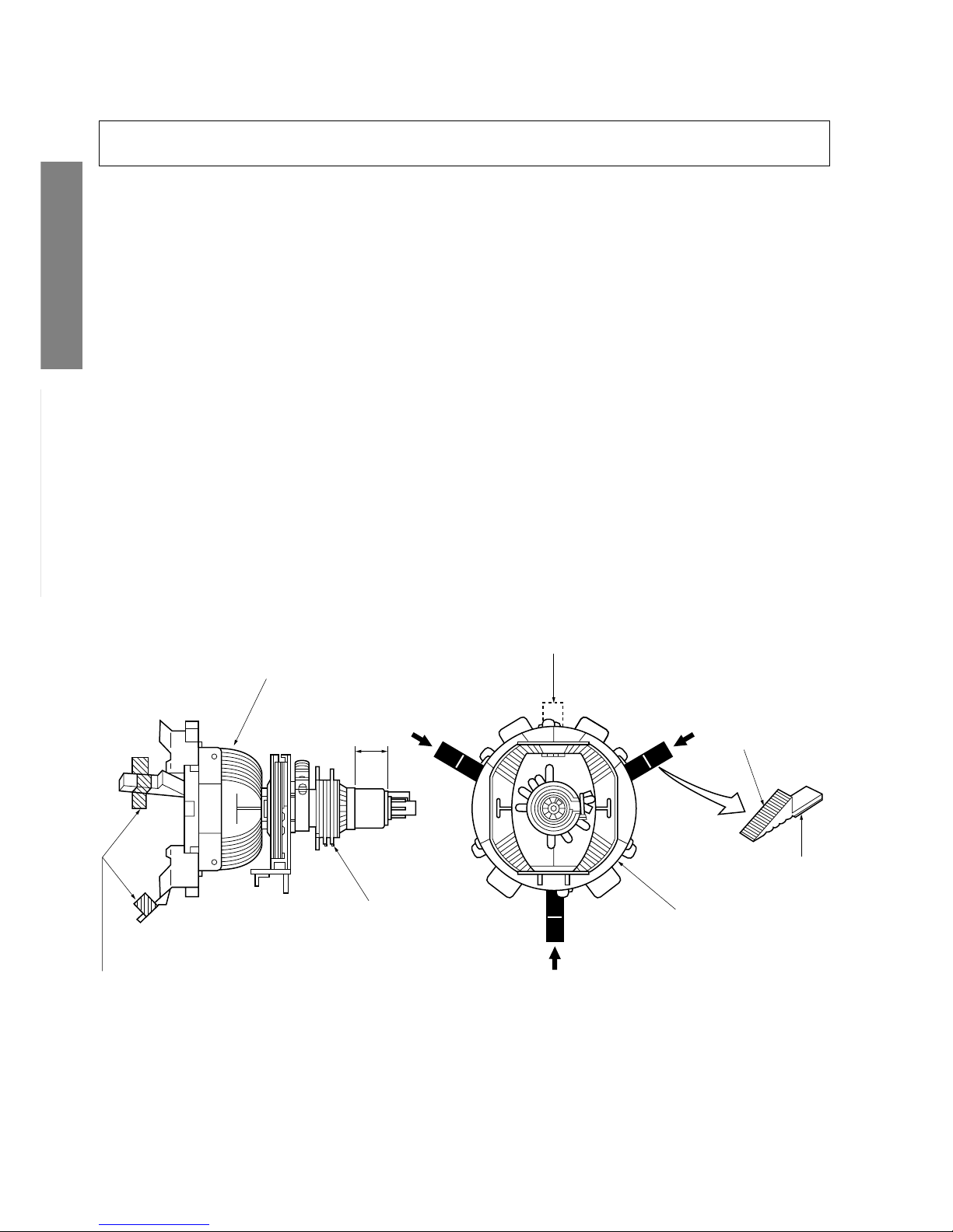
Note: The PURITY/CONVERGENCE MAGNET assembly and rubber wedges need mechanical positioning.
Refer to figure 1.
Mounting position of the purity magnet assembly should fit to same position as old one because slightly difference to
the position depend on a kind of tube.
*
There are no adjustment of purity and convergence in some picture tube (Unified with purity magnet)
GLASS CLOTH
TAPES
DEFLECTION
YOKE
TEMPORARY
MOUNTING
RUBBER WEDGE
ADHESIVE
DEFLECTION
YOKE
PURITY/
CONVERGENCE
MAGNET ASS'Y
29.1mm(28", 29")
25mm(25")
19mm(19", 20", 21")
14mm(13", 14")
Figure 1.
COLOR PURITY ADJUSTMENT
NOTE : Before attempting any purity adjustments, the receiver
should be operated for at least fifteen minutes.
1. Demagnetize the picture tube and cabinet using a degaussing coil.
2. Set the brightness and contrast to maximum.
3. Use a green raster from among the built-in test signals.
4. Loosen the clamp screw holding the yoke and slide the
yoke backward or forward to provide vertical green belt
(zone) in the picture screen.
5. Remove the Rubber Wedges.
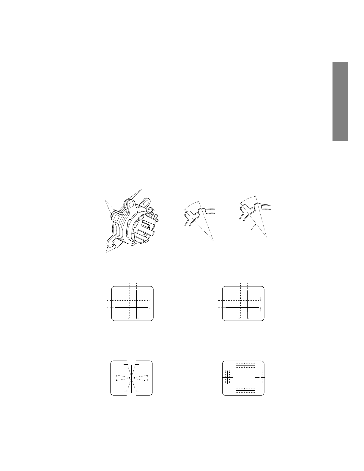
6. Rotate and spread the tabs of the purity magnet (See figure 2.) around the neck of the picture tube until the green
belt is in the center of the screen. At the same time, enter
the raster vertically.
7. Slowly move the yoke forward or backward until a uniform
green screen is obtained. Tighten the clamp screw of the
yoke temporarily.
8. Check the purity of the red and blue raster.
– 5 –
GENERAL ADJUSTMENTS
SPECIFIC INFORMATIONS
CONVERGENCE ADJUSTMENTS
NOTE: Before attempting any convergence adjustments, the
receiver should be operated for at least fifteen minutes.
■ CENTER CONVERGENCE ADJUSTMENT
1. Use the cross-dot pattern from among the built-in test signals.
2. Set the brightness and contrast for well defined pattern.
3. Adjust two tabs of the 4-Pole Magnets to change the angle between them (See figure 2.) and superimpose red
and blue vertical lines in the center area of the picture
screen.
4. Turn the both tabs at the same time keeping the angle
constant to superimpose red and blue horizontal lines at
the center of the screen.
5. Adjust two tabs of 6-Pole Magnets to superimpose red/
blue line and green one. Adjusting the angle affects the
vertical lines and rotating both magnets affects the horizontal lines.
6. Repeat adjustments 3, 4, 5 keeping in mind red, green
and blue movement, because 4-Pole Magnets and 6-Pole
Magnets have mutual interaction and make dot movement
complex.
■ CIRCUMFERENCE CONVERGENCE ADJUSTMENT
1. Loosen the clamping screw of deflection yoke slightly to
allow the yoke to tilt.
2. Temporarily put a wedge as shown in figure 1. (Do not
remove cover paper on adhesive part of the wedge.)
3. Tilt front of the deflection yoke up or down to obtain better
convergence in circumference. (See figure 3.) Push the
mounted wedge into the space between picture tube and
the yoke to fix the yoke temporarily.
4. Put other wedge into bottom space and remove the cover
paper to stick.
5. Tilt front of the yoke right or left to obtain better convergence in circumference. (See figure 3.)
6. Keep the yoke position and put another wedge in either
upper space. Remove cover paper and stick the wedge
on picture tube to fix the yoke.
7. Detach the temporarily mounted wedge and put it in another upper space. Stick it on picture tube to fix the yoke.
8. After fixing three wedges, recheck overall convergence.
Tighten the screw firmly to fix the yoke and check the yoke
is firm.
9. Stick three adhesive tapes on wedges as shown in figure
1.
Figure 2.
BLU RED
BLU
RED
RED/BLU GRN
RED/BLU
GRN
B
G
R
R
G
B
BGR
RGB
BGR
RGB
R
G
B
B
G
R
4-POLE MAGNETS MOVEMENT
INCLINE THE YOKE UP (OR DOWN)
6-POLE MAGNETS MOVEMENT
Center Convergence by Convergence Magnets
Circumference Convergence by DEF Yoke
INCLINE THE YOKE RIGHT (OR LEFT)
Figure 3. Dot Movement Pattern
4-POLE
MAGNETS
PURITY
MAGNETS
6-POLE
MAGNETS
ADJUST THE ANGLE
(VERTICAL LINES)
FIXED
ROTATE TWO TABS
AT THE SAME TIME
(HORIZONTAL LINES)
CONVERGENCE MAGNET ASSEMBLY ADJUSTMENT OF MAGNETS
– 6 –
GENERAL ADJUSTMENTS
SPECIFIC INFORMATIONS
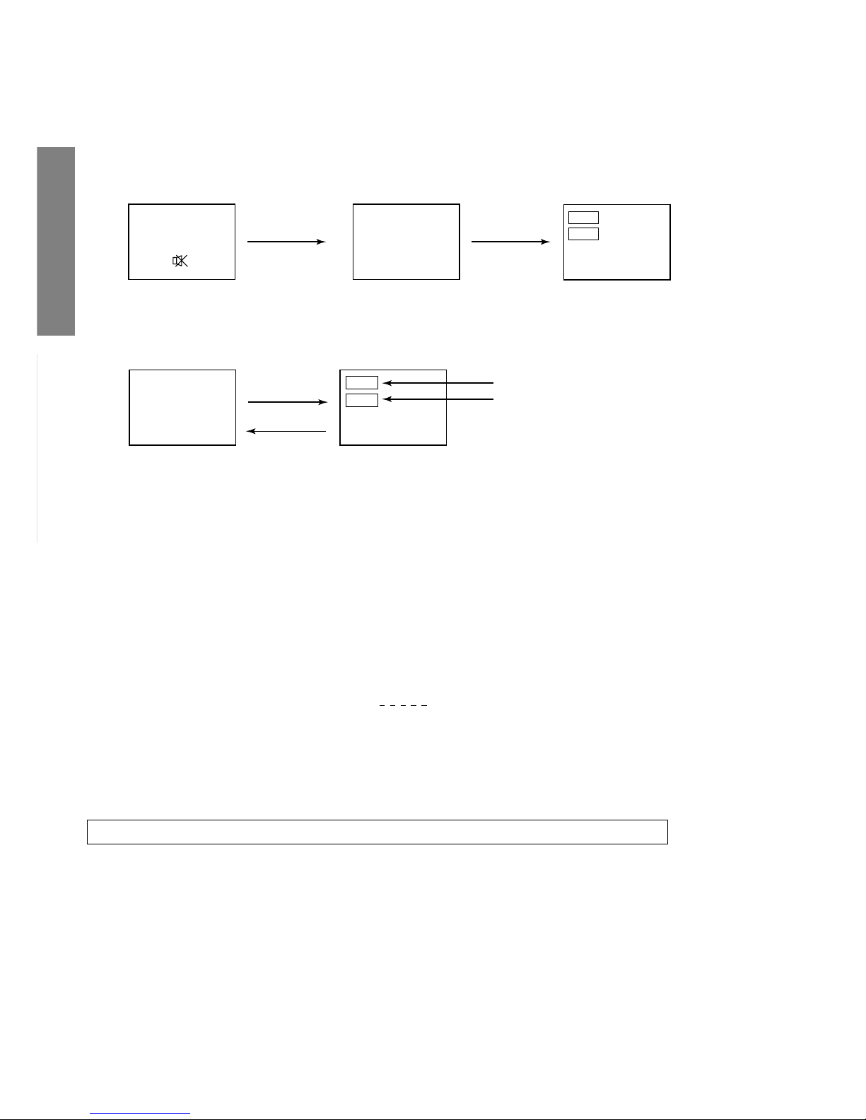
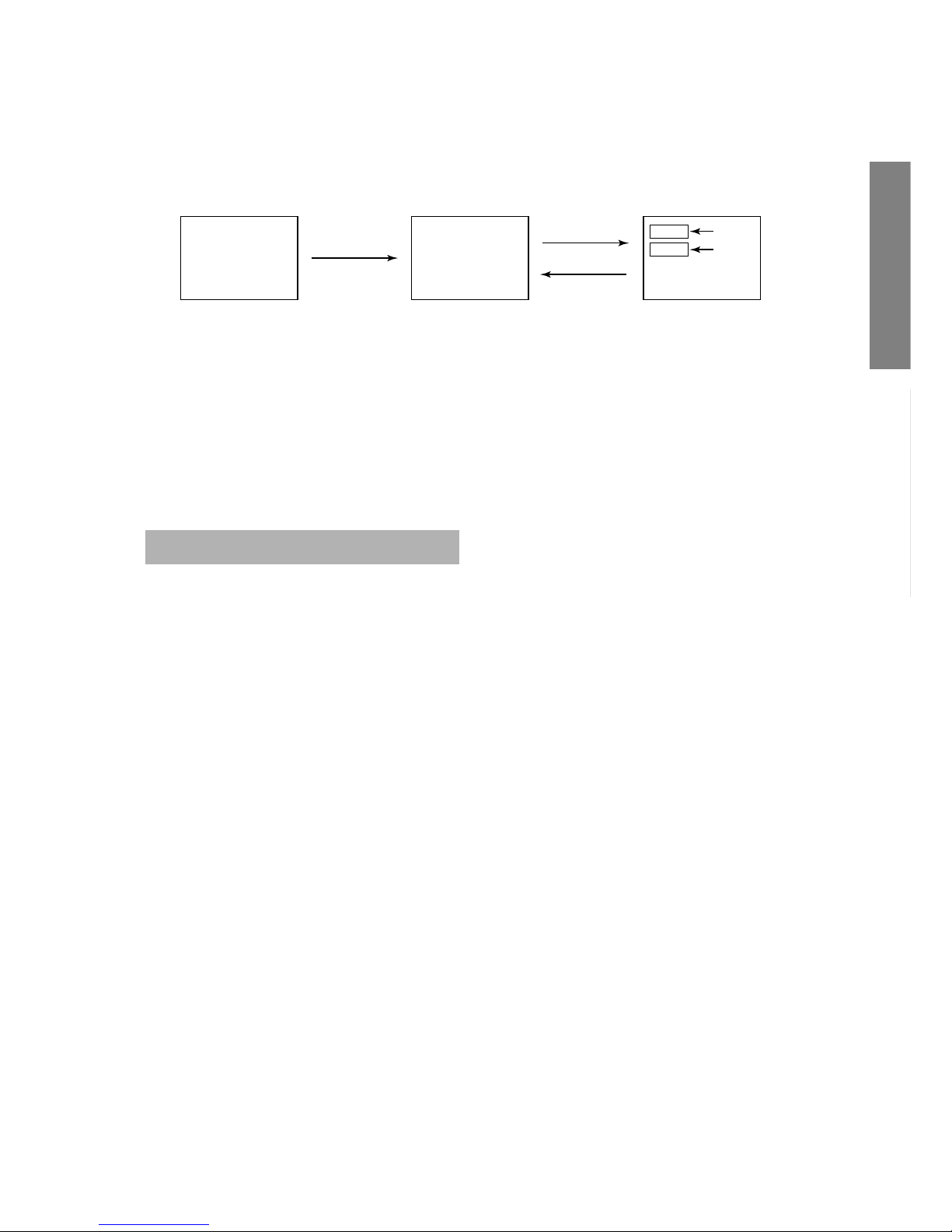
SERVICE MODE
1. ENTERING TO SERVICE MODE
S
(Service mode display)
Item
Data
3) While pressing the o button,
press MENU button on TV set.
2) Press o button again to
keep pressing.
2. DISPLAYING THE ADJUSTMENT MENU
1) Press MENU button on TV.
3. KEY FUNCTION IN THE SERVICE MODE
The following key entry during display of adjustment menu provides special functions.
A single horizontal line ON/OFF: - / - - button (on Remote) or a button (on TV)
Test signal selection : a button (on Remote)
Selection of the adjustment items : Channel s/t (on TV or Remote)
Change of the data value : Volume ; +/– (on TV or Remote)
Adjustment menu mode ON/OFF : MENU button (on TV)
Initialization of the memory (QA02) : CALL + Channel button on TV (s)
Reset the count of operating protect
circuit to “00”: CALL + Channel button on TV (t)
“RCUT” selection : 1 button
“GCUT” selection : 2 button
“BCUT” selection : 3 button
“CNTX” (or “SCNT”) selection : 4 button
“COLC” selection : 5 button
“TNTC” selection : 6 button
Test audio signal ON/OFF (1kHz) : 8 button
Self diagnostic display ON/OFF : 9 button
1) Press o button once on
Remote Control.
Adjustment mode
Press
Press
Service mode
Item
Data
S
Color thickness correction
note: Displayed differently as shown below, de-
pending on the setting of the receiving color
system.
COLP (PAL)
COLC (NTSC)
COLS (SECAM)
CAUTION : Never try to perform initialization unless you have changed the memory IC.
– 7 –
GENERAL ADJUSTMENTS
SPECIFIC INFORMATIONS
4. SELECTING THE ADJUSTING ITEMS
1) Every pressing of CHANNEL s button in the service mode changes the adjustment items in the order of table-2.
(t button for reverse order)
Refer to table-2 for preset data of adjustment mode.
(See SETTING & ADJUSTING DATA on page 13)
5. ADJUSTING THE DATA
1) Pressing of VOLUME ; +/– button will change the value of data in the range from 00H to FFH. The variable
range depends on the adjusting item.
6. EXIT FROM SERVICE MODE
1) Pressing POWER button to turn off the TV once.
■ INITIALIZATION OF MEMORY DATA OF QA02
After replacing QA02, the following initialization is required.
1. Enter the service mode, then select any register item.
2. Press and hold the CALL button on the Remote, then press the CHANNEL s button on the TV. The initialization of QA02 has
been complated.
3. Check the picture carefully. If necessary, adjust any adjustment item above.
Perform “Auto search Memory” on the owner’s manual.
CAUTION: Never attempt to initialize the data unless QA02 has been replaced.
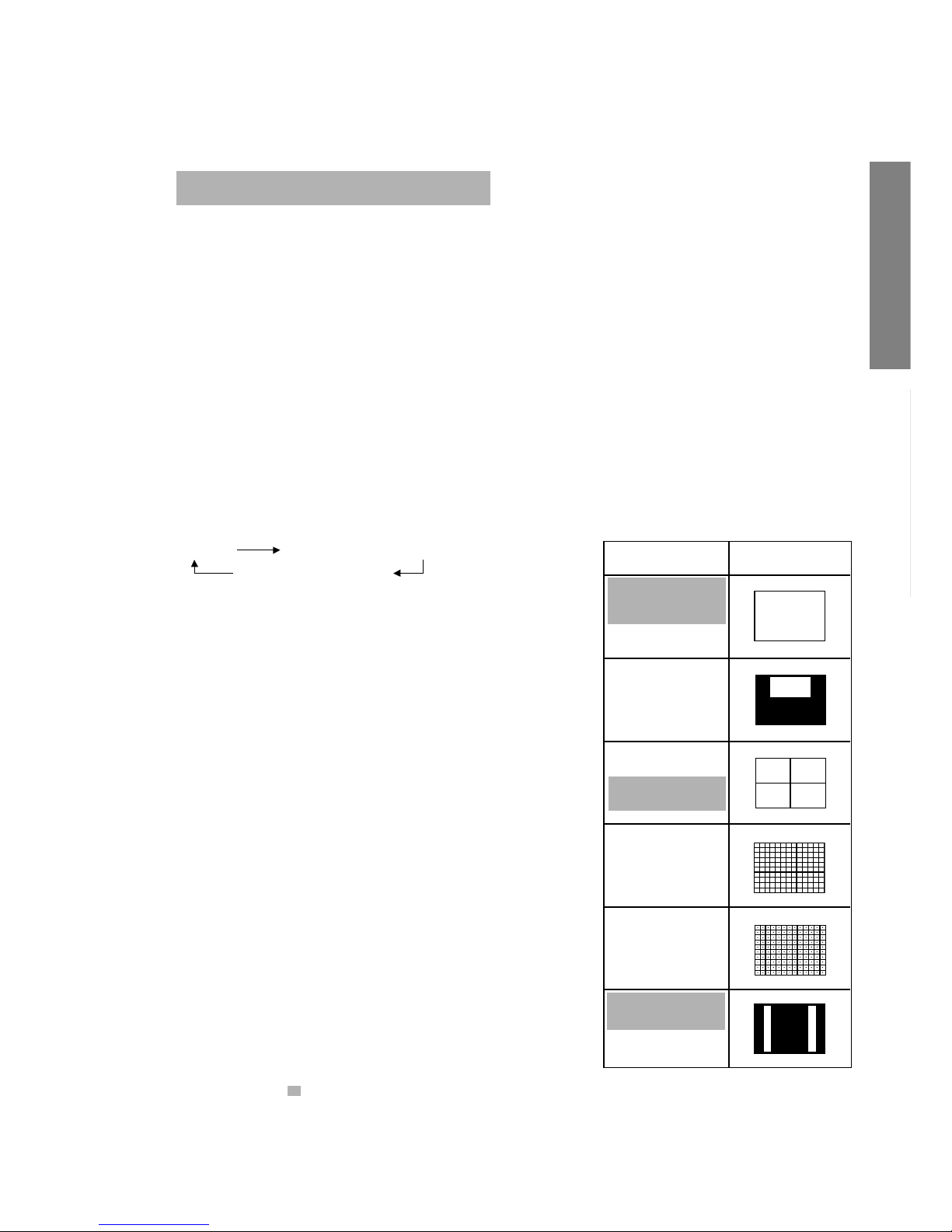
7. TEST SIGNAL SELECTION
1) Every pressing of a button on the Remote Control changes the built-in test patterns on screen as described below
in SERVICE MODE.
Signals Picture
• Red raster
• Green raster
• Blue raster
• All Black
• All White
• Black & White
• Black cross-hatch
• White cross-hatch
• Black cross-dot
• White cross-dot
• Black cross-bar
• White cross-bar
• Black cross-bar
on green raster
• H signal (white)
• H signal (black)
*
The signals marked with are not usable to display in the Test signal for some model.
Signal off
NTSC signals (14 patterns)
PAL signals (14 patterns)

– 8 –
GENERAL ADJUSTMENTS
SPECIFIC INFORMATIONS
8. SELF DIAGNOSTIC FUNCTION
1) Press “9” button on Remote Control during display of adjustment menu in the service mode.
The diagnosis will begin to check if interface among IC’s are executed properly.
2) During diagnosis, the following displays are shown.
23******
POWER : 00
BUS LINE : OK
BUS CONT : OK
BLOCK : UV V1
QT01
<SELF CHECK>
Part number of microprocessor(QA01)
Operation number of protecting circuit ----“00” is nor-
mal.
When indication is other than “00”, overcurrent apts to
flow, and circuit parts may possibly be damaged.
BUS LINE CHECK ----“OK” is normal.
“SDA1-GND” ------------- SDA-GND short circuit.
“SCL1-GND” -------------- SCL-GND short circuit.
“SCL1-SDA1” ------------- SCL-SDA short circuit.
BUS CONT ----“OK” is normal.
When indication shows “Q uuu NG”, the device with
the number may possibly be damaged.
BLOCK
UV : TV reception mode
V1 : VIDEO input mode (a1)
Indicated color of mode now selected : Green and Red
Indicated color of other modes : White
Green : Normal
Red : The microprocessor operates to provide judgement
of no video signal. The red color is still indicated
though the signal is input, failure may exist in input
signal line including QT01.
QT01 : In case of indication green ---Normal
In case of indication red with input signal---Failure may exist in output line including QV01.
NOTE: Component which controls character display on
screen is QT01. If this display function fails to operate due to damage in QT01, self diagnosis procedure is as follows.
(1) In case that power indicator is blinking with
interval of 0.5 seconds; it means protecting circuit (Current limiter) is operating, and circuit
components may possibly be damaged. Check
related components.
(2) In case that power indicator is blinking with
interval of 1 second; Protecting circuit does
not operate, but a part of Bus line does not
operate normally. Check Bus line.
*
The items marked with are not usable to display in the SELF DIAGNOSTIC FUNCTION for some model.
– 9 –
GENERAL ADJUSTMENTS
SPECIFIC INFORMATIONS
DESIGN MODE
1. ENTERING TO DESIGN MODE
ITEM
DATA
S D
Press
(Design mode) (Adjustment mode)
Press
3) Press MENU button on TV.
2) While pressing o (or CALL) button on
Remote and press MENU button on TV.
1) Select the Service mode.
2. SELECTING THE ADJUSTING ITEMS
Every pressing of CHANNEL t button in the design mode changes the adjustment items in the order of table-3.
(s button for reverse order)
Refer to table-3 for data of design mode.
(See SETTING & ADJUSTING DATA on page 13)
3. ADJUSTING THE DATA
Pressing of VOLUME s or t button will change the value of data.
When QA02 is initialized, items “OPT0” and “OPT1” of DESIGN MODE are set to the data of the representative model of this
chassis family.
Therefore, because ON-SCREEN specification remains in the state of the representative of model. This model is required to
reset the data of items “OPT0” and “OPT1”.
 Loading...