

Page 1
15VL
33
l
g
r
g
Owner's manua
Bedienungsanleitun
Manuel de l'utilisateu
Gebruiksaanvijzin
Page 2

List of contents
Special features ..............................................................2
Safety instructions .........................................................3
Getting started ...............................................................4
Aerial connection.............................................................4
Switching on....................................................................4
Battery fitting..................................................................4
Control unit....................................................................5
Front and rear panel.........................................................5
External connections table...............................................6
Remote control ................................................................6
Using the TV ..................................................................7
Tuning the TV .................................................................8
Automatic tuning .............................................................8
Manual tuning..................................................................9
Program organising .......................................................10
TV setup .......................................................................11
Sound menu ...................................................................11
Sound Features ..............................................................12
Picture menu..................................................................13
Features Menu ...............................................................13
Using teletext...........................................................15-16
Connecting external equipment............................18-24
Help and service tips ...................................................25
1
Technical specifications table .....................................26
Page 3

Television
Thank you for buying this television which is designed to give you many years of
satisfactory service.
You may already be familiar with using a television but do please take time to read these
instructions. They are designed to familiarise you with the unit’s many new features
and to ensure you get the very best out of your purchase.
Special features
• 15” TFT-LCD XGA Panel
• 1024x768 resolution
• 16,722,216 colors (8 bit)
• CATV
2
• 430 cd/
• 400:1 Contrast ratio
• 2x2W Stereo Sound
• 124 page teletext
• Wide viewing angles
• 1 Scart, AV, Audio Out.
• Low Power Consumption
brighthness
• AVL
• ATS
• Intelligent programme switch
• On timer
• Off timer
• Graphical equaliser
• On screen display
• Manual fine tuning
• 100 Programme memory
• Full function remote control
• Child Lock
Page 4
Safety is Important
Your safety and the safety of others is important. Please, therefore, ensure you read
the Safety
instructions
before you operate this television.
Safety instructions
Read all the safety instructions before first use of your TV.
!
• Position the television so that direct light does not fall on
the screen. Excessive light will cause a washed out effect.
• Position the power supply lead and other leads so that
they are not likely to be walked on or pinched by things
placed on or against them.
• Do not place objects filled with liquid such as vase or
flower pot near the television.
• Do not expose the TV to dripping or splashing of liquids.
• Do not place naked flame sources such as lighted candles
on the TV set.
• Make sure that no naked flame sources, such as lighted
candles, are placed on top of the appliance.
• Do not place the television near heat sources such as
radiators, ovens, stoves, etc.
• Do not push, hit or screw the screen of your product.
• The heat built up in the set escapes through ventilation
holes, so do not cover the set by drapes, clothes etc. that may
block air circulation. Do not place the television on carpet
or soft furnishings.
• NEVER let children push anything into the holes or slots
on the case.
• Clean the TV Screen using a slightly damp cloth or chamois
leather. Never use abrasive cleaning agents like liquid or
aerosol cleaners.
• Remove the mains plug from the socket outlet while cleaning.
• Never apply pressure on the screen when cleaning.
• Never put your screen on hard objects. Your TFT screen
may be damaged.
3
12 V
5 A
• Your TV set is designed to operate with the adapter provided
12V DC.-5A. If you leave power cord at the mains plug the
adaptor will get hot altough the unit is off. Better to unplug
the cord from the mains if you will not use the unit for a long
time.
• Use the adaptor supplied with the product. Never connect
any other power sources to the product.
Turn off the TV set from mains switch before unplug the
adaptor mains. Be sure your hands are dry.
Page 5

Getting started
Remove your Television carefully
from the box. You may wish to
store the packaging for future use.
In the box
Inside the cartoon box you should have:
• Accessories box
• Power cord
• Adapter
• Remote control
• Batteries
4
Read these instructions before use.
Aerial connection
To connect an aerial, plug the aerial lead
into the aerial socket on the rear of the
TV.
You can use an outdoor or indoor aerial.
However, if you use an indoor aerial the
quality of the reception may be reduced
and adjustment of the aerial may be
required when changing programs.
Please note
If you live in a poor reception area or use an
indoor aerial you may experience loss or
corruption of teletext transmissions.
Please Note
When not in use disconnect the plug
from the mains power supply.
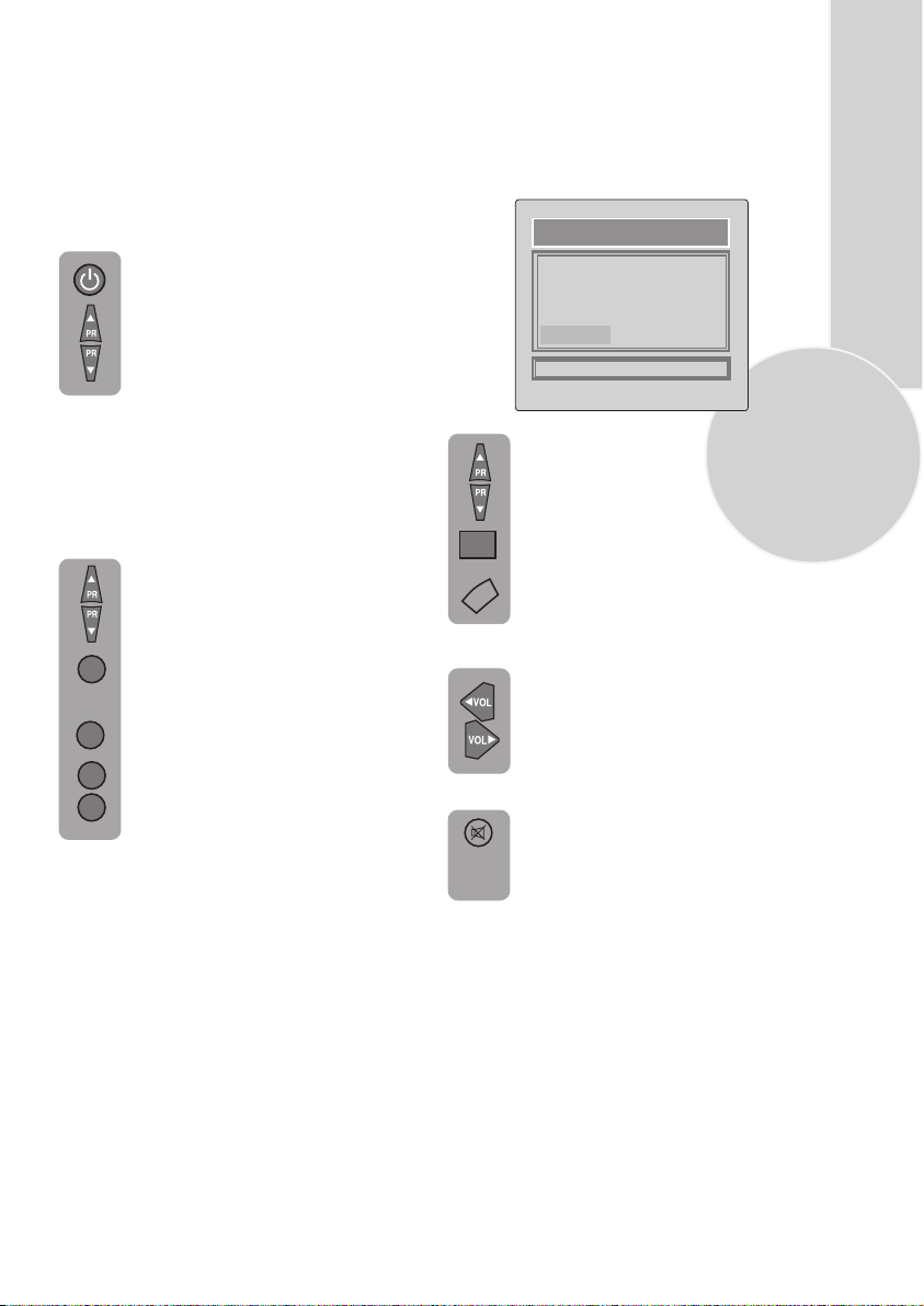
4. Press the Power button on
the front of the TV. The
standby indicator will
illuminate.
7
5. Press a Numeric button or the
Program up or Program down
button on the remote handset or
Program up, Program down
or MENU button on the front panel to
switch the TV on.
The standby indicator remains on.
The picture will appear after a
few seconds.
Press the Standby
the TV to standby. The standby
indicator will brighter.
Please Note
Do not leave the television on standby
unattended or overnight.
Switching the TV on for the first time
To install your TV, please read the sections
“TV controls” and “ Tuning the television”.
button to switch
Battery fitting
Insert the 2 AAA Batteries supplied into
the compartment on the rear of the remote
control, ensure you follow the polarity
diagram inside the compartment.
Switching on and First Use
1. Connect the power cord to the mains plug.
2. Connect the input socket of the adapter to the
12 V DC socket at the back panel of the LCD TV.
3. Connect adapter to the mains plug.
Note 1: Your TV will move to stand-by mode
in five minutes when there is no broadcast signal.
Note 2: Your TV is equipned to operate with front
panel buttons, “MENU”, “PR+”, “PR-”, “+”, “-”
in case your R/C is broken or you run out of
batteries.
Page 6
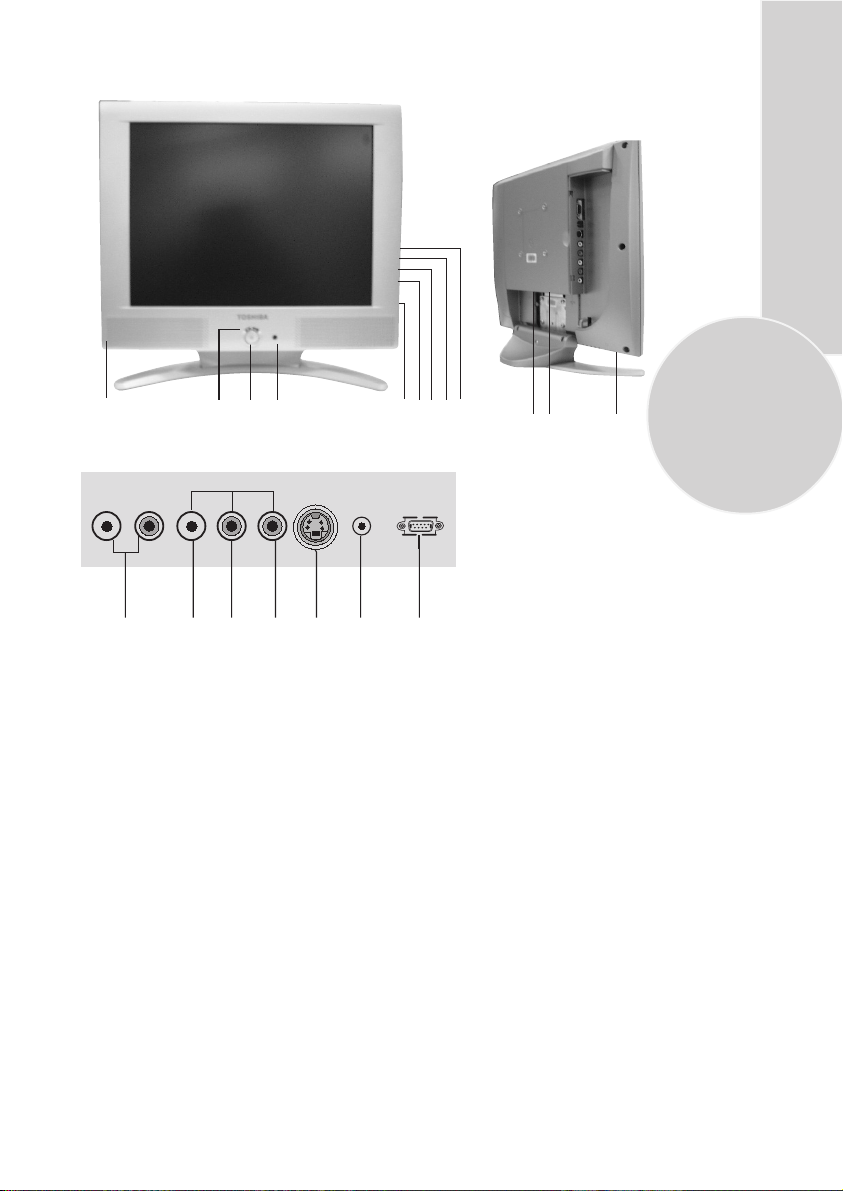
Control Unit
9
AUDIO OUT
1.
Stand-by
2.
Power on / off
3.
Remote control
4.
Menu button
5.
Volume up
6.
Volume down
7.
Program up
8.
Program down
9.
Speaker
10.
Audio RCA (R)
2
1
3
AV3
L R VIDEOL R S-VHS
1011 12 1316 18 19
AVS
11.
Audio RCA (L)
12.
Video input CINCH connector
13.
S-VHS
14.
Headphone
15.
Antenna input
16.
Audio out (R,L)
Scart
17.
DC 12V Power supply input
18.
VGA
19.
DC 12V VGA
4 5 678
141517
Please note
• See the external connections table on next page for avaible connections.
• Do not use Video RCA and S-Video connections at the same time, otherwise they will effect the
picture each other.
• RGB inputs from scart will give you better picture quality.
5
Page 7
External connections table
STD
Picture tube
size/type
AV1 Scart
Headphone
socket
Audio/Video
RCA
S-Video
socket
Back audio
out
15”
4:3
STD.
STD.
STD.
STD.
STD.
: Standart
OPT
: Optional
N/A
: Not available
6
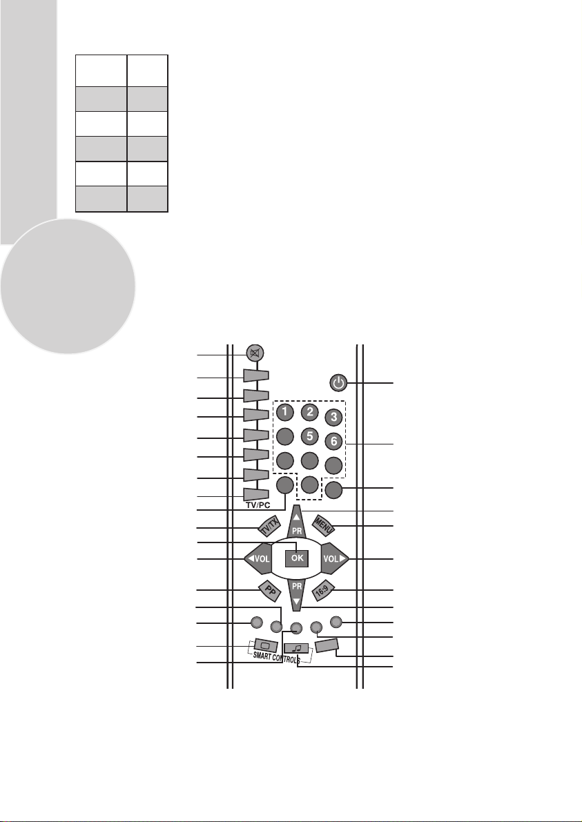
Remote control
Mute
Index page (Text)
Reveal info (Text)
Double heigth (Text)
Stop button
Sub page button (Text)
TV mode button (Text)
Text mode button
AV
TV/Teletext
OK
Volume down
P100
REVEAL
DOUBLE
HOLD
SUB
UPDATE
MIX
4
7
AV
Standby
Numeric
8
9
0
-/--
Two digit
Program up
Menu
Volume up
Personal preference
Green teletext button
Picture Menu button
Red teletext button
Sound Menu button
Picture smart control
Yellow teletext button
Program table button
SWAP
16:9 Picture format
Program down
Features Menu button
Blue teletext button
Setup Menu button
Swap
Sound smart control
Page 8
Using the TV
Turning on for the first time and Tuning
TV controls
Stand-By mode
When your TV is working on, press
the red “STAND-BY” button on the
right upper corner of your remote
control to switch off and the StandBy indicator (Led) will be brighter.
To turn on your TV again, press one
off the numaric buttons, Program up
or Program down.
Please Note: If you will not use your TV for
a long time, do not leave it on Stand-By mode,
instead switch it off from the power button
on the front panel of the TV set.
Programme selection
Press the Program up or Program
down buttons on the TV or remote
control or press a Numeric button
to select a programme.
1
To select a programme whose
number is greater than 9 using the
numeric buttons, press the -/--
-/--
button first and then press the two
Numeric buttons. For example, to
1
2
button followed by and then12.
-/--select programme 12, press the
You can also select a program by
pressing in the Yellow button to
see the Program Table.
OK
TV/TX
Volume
Mute
PROGRAM TABLE
00. ----
01.
02. BBC
03.
04.
SKIP
Use the Program up and Program
down buttons to scroll through the
programme numbers. When you
find the program number you want
press theOK button again.
Press theTV/TX button to close the
Program Table.
Press the Volume + or Volume -
button on the TV or the Vol or
Vol button on the remote control.
A sound level bar will appear on the
screen.
To mute the sound press the Mute
button on the remote control. A
loudspeaker symbol will appear on
the screen.
MOVE
05.
06.
07.
08.
09.
NAME
10.
11.
12.
13.
14.
DELETE
7
Page 9
Press the Mute button again to
restore the sound. The symbol
will disappear.
Pressing Volume up buttons
will also restore the sound.
But pressing the Volume down
button will decrease the volume
PP
without restoring.
Personal preference. Press the
PP
PP
button to revert to the
default settings for the TV.
Swap
(See TV setup).
Select the programme you would
like to recall by pressing SWAP
SWAP
button. Selected programme
8
number will appear on the lower
left side of the screen. While
watching any programme, you
can recall the selected one by
pressing SWAP button again.
If you press swap button again you
can recall the last programme you
watched. You can cancel SWAP
function by pressing MENU button.
SWAP
PR 01
PR 11 PR 12
AV
Your TV has 1 scart so every time
AV
you press your AV button, your input
will change as follows:
1AV1 when using SCART socket 1
(RGB support).
2AV2 when using RCA socket.
3AVS when using the S-video socket.
PR 13...
SWAP
Tuning the television
There are two ways of tuning your television:
Manual, where you control the tuning process
or
Autoprogram where the television does it all
automatically.
Your TV will sort all the channels with the
ATS. Sorting will be performed in the
following order:
a- Selected country’s channels with teletext
and channel names.
b- Selected country’s channels with teletext
and without channel names.
c- Selected country’s channels without
teletext.
d- Foreign channels with teletext and channel
names.
Please Note
If the TV is set to a channel with no signal the
TV will return to standby in 5 minutes.
The last minute remaining is displayed on
the screen.
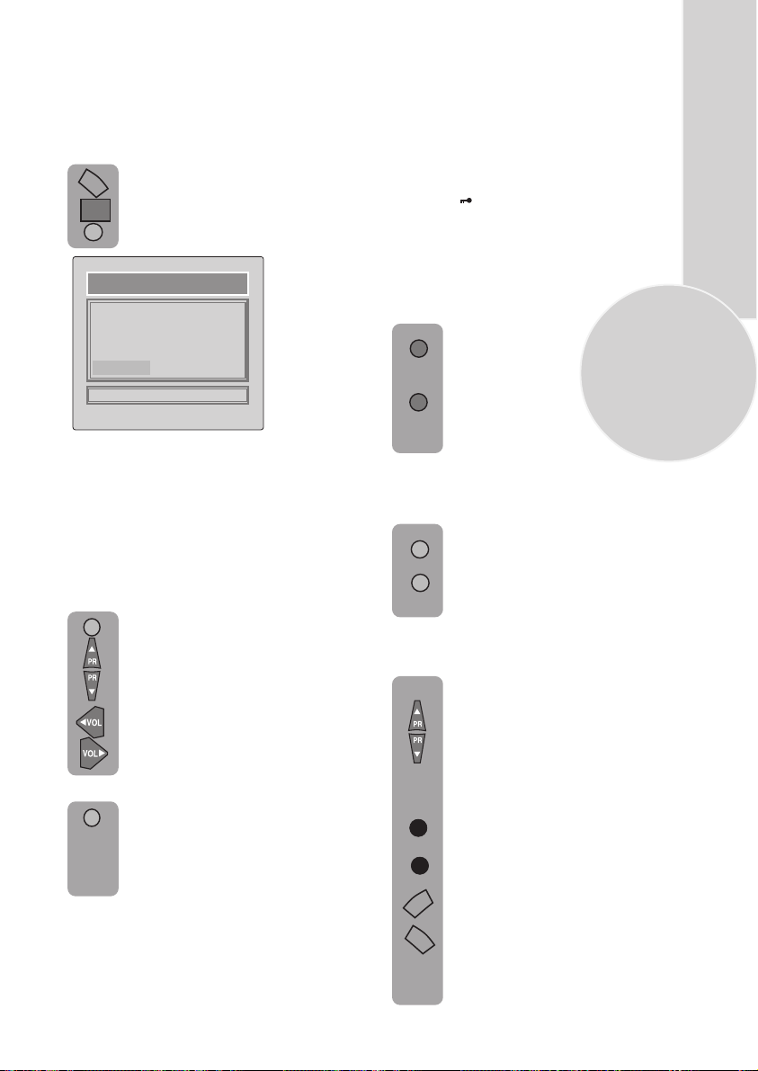
PR 01
Automatic tuning (Autoprogram)
There are two ways to access the SETUP
menu:
Press the blue Setup button.
or
MENU
Press the Menu button and use the
Program down button to select
SETUP. Press theOK button to
enter the SETUP menu.
OK
Press the AVbutton again to
AV
return to TV.
MAIN MENU
SOUND
PICTURE
PROGRAM TABLE
SETUP
FEATURE
CHANNEL
SYSTEM
SEARCH
FINE TUNE
PROGRAM NUMBER
AUTO PROGRAM
STORE
SETUP
Page 10
Please note
The system will be displayed automatically on
SYSTEM row i.e.BG, L, I or DK depending
the receiving broadcasting system of your
country. In some countries the broadcasting
system can be both in BG/DK or BG/LL´.
Only the TV sets produced with Pal Secam
BG/DK or Pal Secam BG/LL´ systems can
receive both BG/DK or BG/LL´ broadcasts.
In this case the user can select the required
SYSTEM using Volume up/down buttons.
Please note
If you do not press any buttons for 15 seconds
the TV will exit the menu system.
Use the Program down button to
select AUTOPROGRAM and
press
OK
the OK button. A list of
countries will appear. Select
the desired country using
Program and Volume buttons.
When you are sure the aerial is
OK
connected properly press the OK
button. Autoprogam will start.
To cancel Autoprogram whilst it
MENU
working press the Menu button
is
repetitively.
As Autoprogram stores a channel
it will appear briefly on the screen
before the search continues.
Your TV is now tuned and ready to use.
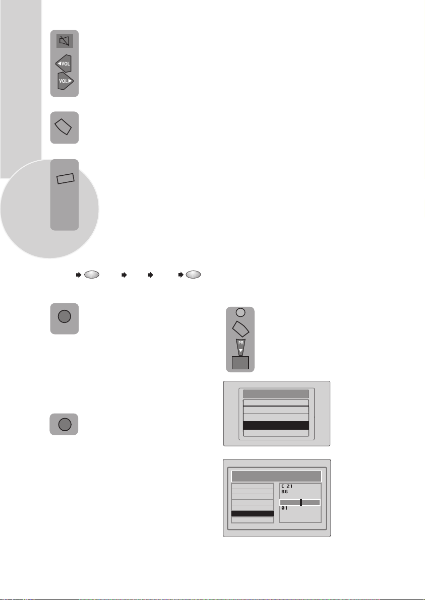
Manual tuning
If you want to tune manually:
In the Setup menu select
PROGRAM NO
using
the Program down button
and use the Volume up
button to change the Program No
to 01.
Starting with Program 01, tune
in the first channel as follows:
Use the Program down button
to select SEARCH.
Press the Volume up or Volume
down button to start the tuning
search.
When the search finds a strong
channel signal it will stop
searching. The picture will appear.
CHANNEL
SYSTEM
SEARCH
FINE TUNE
PROGRAM NUMBER
AUTO PROGRAM
STORE
SETUP
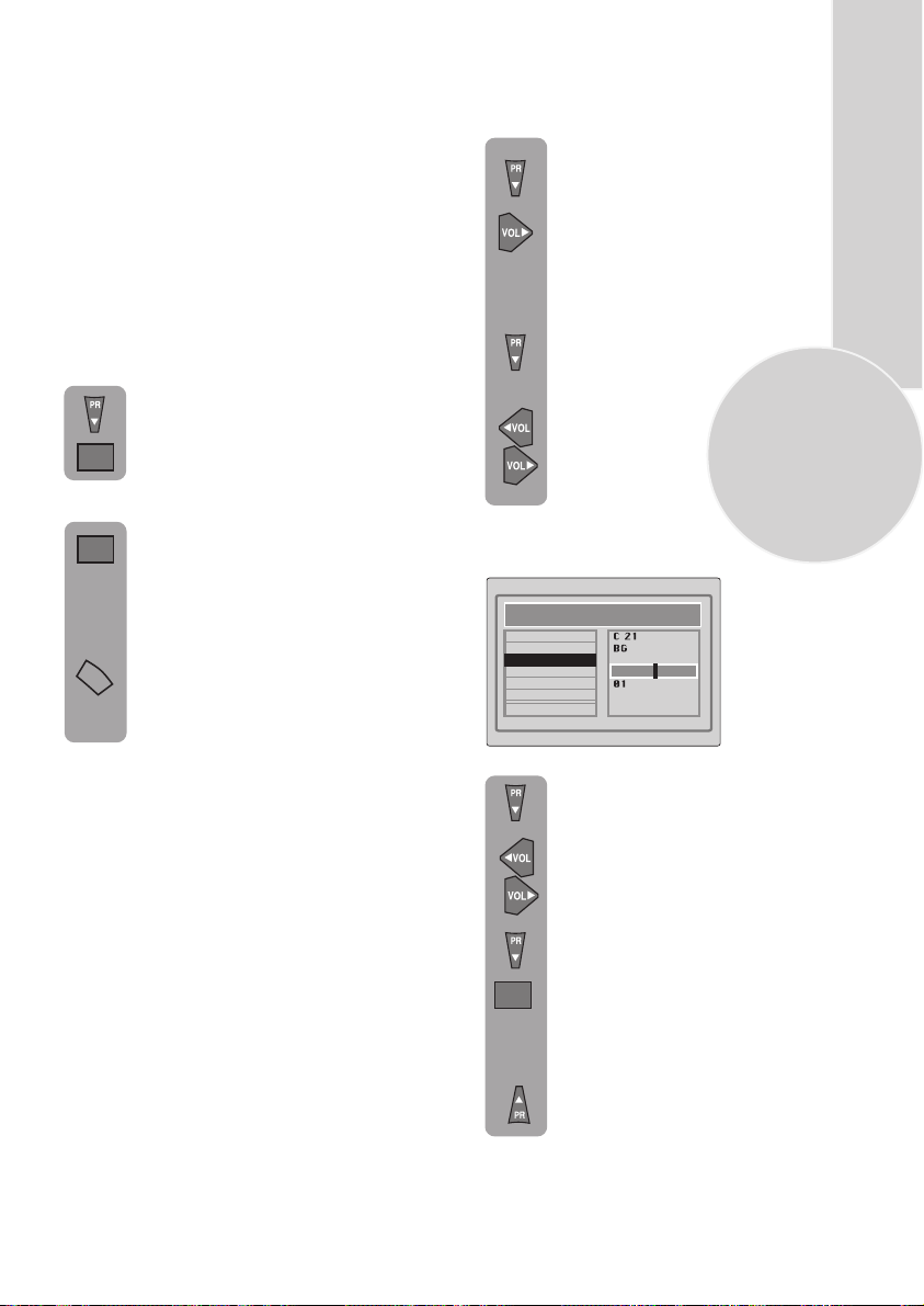
Use the Program down
select PROGRAM NO.
9
button to
Please note:
If auto sort fails to arrange the programmes
in the required sequence please refer to
programme organising.
Volume up/down
Use the
buttons
to select the desired
programme number.
Use the Program down button to
select STORE. Press theOKbutton
and STORED will appear on the
OK
STORE line.
You have now stored the first
channel.
Use the Program up button to
select again SEARCH and
continue the tuning procedure
until you have tuned in all the
programmes you want or the
television can receive.
or numeric
Page 11
10
Tuning with channel numbers
Enter the SETUP menu by pressing
the blue button.
OK
Press OK button when CHANNEL
row is blue.
Use OK button to select “S” for
OK
cable channels and “C” for
terrestrial broadcast.
7
Enter the channel number using the
Numeric buttons or use the
Volume up/down buttons to tune
channels.
Use the Program down button to
select PROGRAM NUMBER.
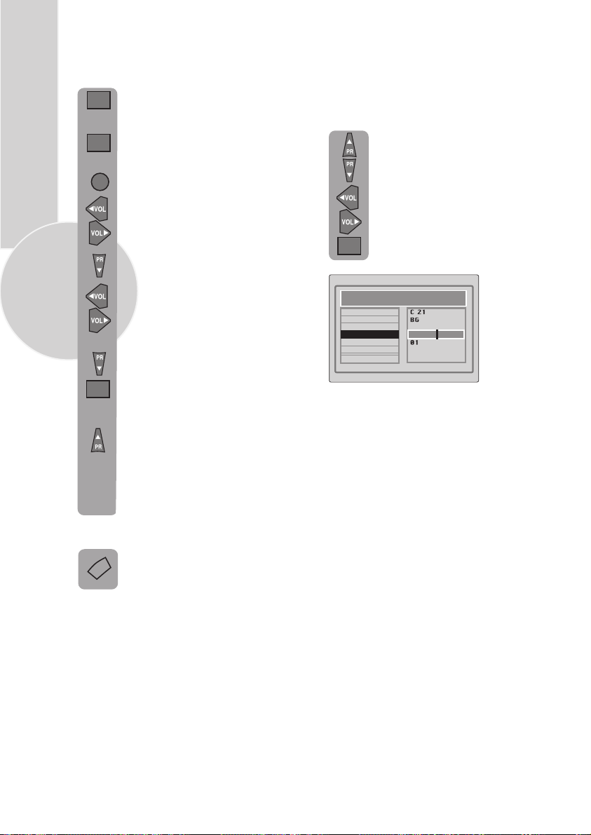
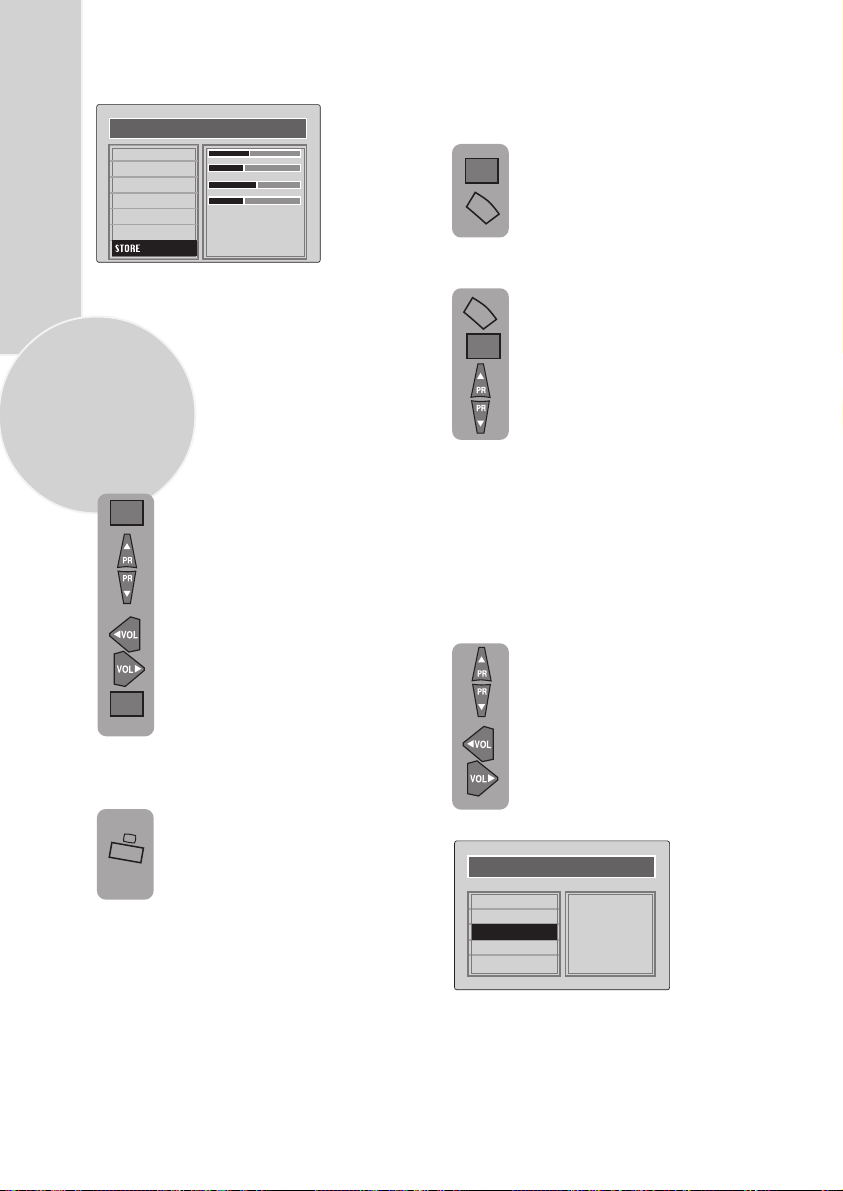
Fine tuning
Although the search and Autoprogram
will automatically try and tune to the
best reception, in areas of poor reception
a bit of fine tuning may be required.
In the SETUP menu use the
Program up/down buttons to
select FINE TUNING. Use the
Volume up and Volume down
buttons to fine tune.
When you have finished use the
Program down button to select
OK
STORE and press the OK button.
Use the Volume up/down or
numeric buttons to select the desired
programme number.
Use the Program down button to
select STORE. Press the
and STORED will appear on the
OK
STORE line.
You have now stored the first
channel.
Use the Program up button to
select again CHANNEL and continue
the tuning procedure until you
have tuned in all the programmes
you want or the television can
receive.
To exit the SETUP menu press the
TV/TX
TV/TX button.
OKbutton
CHANNEL
SYSTEM
SEARCH
FINE TUNE
PROGRAM NUMBER
AUTO PROGRAM
STORE
SETUP
Page 12
Program organising
Once you have tuned in all the channels you
want, you can change their programme
number, if required, and name them.
To enter the PROGRAM TABLE
MENU
menu press the Menu button and
OK
select PROGRAM TABLE and press
the OK button or press directly the
Yellow button.
PROGRAM TABLE
05.
00. ----
01.
02. BBC
03.
04.
SKIP
MOVE
The buttons used to edit the programs are
shown at the bottom of the display:
Blue button - Name
Green button - Move
Pink button - Delete
Red button - Skip
06.
07.
08.
09.
NAME
10.
11.
12.
13.
14.
DELETE
Please Note
1. Some TV channels may send their
names with teletext transmission. In this
case their names will be automatically
shown on the name line.
1. Child locked programmes will be
shown as
“ “
To move the programmes
You can move the programmes around the
programme list to the order you want
Select the programme you want to
move and press the
Green button.
The programme will turn to yellow.
Select the number you want to move
and press the Green button
again and the programme will be
moved to that number.
All the following programmes are
shifted down by one place.
To delete a programme
To delete a programme, select it and
press the Pink button.
The programme will be deleted.
11
To name the programmes
You can name the programmes and
AV inputs.
Press theBlue button, the selected
programme will be highlighted.
Use the Program up and Program
down buttons to select the letters
and numbers and the Volume up
and Volume down buttons to
move through the name.
Press the Blue button again to store
the name.
Repeat this process to name all the
programmes.
All the following programmes are
shifted up by one position.
To skip programmes
Skipped programmes will not appear
when you move through the program
list using the Program up/
Program down buttons.
They can still be selected using the
numeric buttons or the OK button.
Select the programs you want to
skip
and press the Red button. The
program will turn red. To unskip the
program press the Red button again.
To exit the PROGRAM EDIT press
TV/TX
the TV/TX button once or the
MENU
Menu button twice.
When you select a programme, the
information you entered in the
PROGRAM EDIT menu will appear
on the top of the screen i.e. P1
BBC1.
This will disappear after
about three seconds.
Page 13
12
TV set up
The TV set up is accessed through a menu
system.
Once you have stored your set up, this is the
set up the TV will default to when you switch
it on.
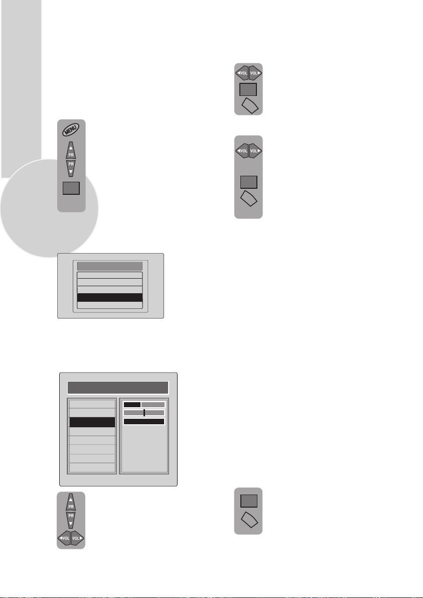
To enter the MAIN menu press the
Menu button.
Once in the MAIN menu use the
Program up and Program down
buttons to select items in the menu
and the OK to access sub menus
OK
or use the coloured fastext buttons
for quick access.
Red button - SOUND
Green button - PICTURE
Pink button - FEATURES
MAIN MENU
SOUND
PICTURE
PROGRAM TABLE
SETUP
FEATURE
Please note
If you do not press any buttons for 15 seconds
the TV will exit the menu system.
Sound menu (red button)
SOUND
VOLUME
BALANCE
SOUND TYPE
SOUND MODE
AVL
EQUALISER
HEADPHONE
STORE
Select the required item in the menu
using the Program up/down buttons
and make the changes pressing
Volume up/down buttons. Use the
OK button to enter HEADPHONE
from main menu.
MONO
SPATIAL
ON
Volume
Sets default volume using the Volume up
and down buttons.
To save your settings, select
STORE
OK
MENU
and press the OK button.
STORED
will be displayed. Press
the Menu button to go back to
the previous menu.
Balance
Sets the sound balance
mode using the Volume up
and down buttons
To save your settings, select
OK
STORE
MENU
STORED
and press the OK button.
will be displayed. Press
the Menu button to go back to the
previous menu.
Sound type
This item shows STEREO when receiving
stereo
transmission and MONO for mono
transmissions.
The TV can be produced to receive the
NICAM broadcasts as a optional
feature.
If the channel you are watching
Nicam stereo the On
Screen Display
is in
will show NICAM STEREO for a
while.
Please Note
If, while watching a nicam stereo channel,
the signal strength drops and the system
cannot receive nicam stereo the OSD will
show MONO. If the signal strength
increases again and nicam stereo can be
received again, the OSD will show
NICAM STEREO.
Dual I/II
Some broadcasters supply the programmes
in two languages. To able to listen the
second language select DUAL II by
SOUND TYPE using Volume up/down
buttons.
To save your settings, select STORE
OK
and press theOK
will be displayed. Press the Menu
MENU
button to go back to the previous
menu.
button. STORED
Page 14
Sound mode
You can select NORMAL or SPATIAL
Volume up/down buttons.
SPATIAL sound is an ‘expanded stereo’. It
gives the impression that the two speakers in
the TV are further apart than they really are.
AVL
TV transmitters have different sound levels.
AVL (automatic volume limiting) maintains
the same sound level as you switch from
program to program.
To apply this press Volume up or down
button and select ON for AVL in Sound
Features menu.
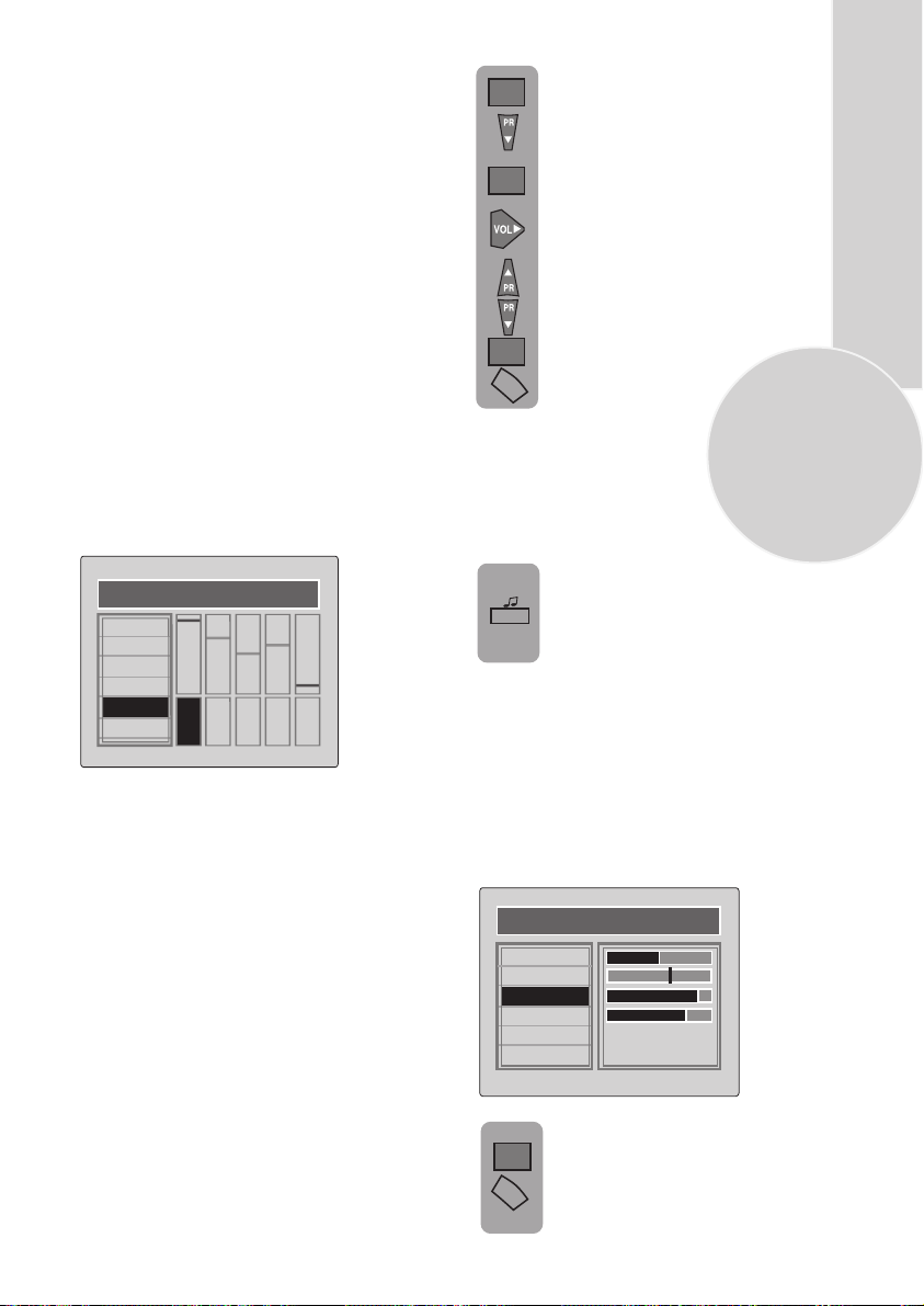
Equalizer
To access the 5 band equalizer menu
press Volume up or down button
and press OK on the Equalizer line.
Press the OK button to enter the
OK
EQUALIZER menu.
Use the Program down button to
select USER1.
Press OK button to adjust the
OK
frequency band levels.
Use the Volume up button to select
the KHz column you want to
change.
Use the Program up/down
buttons to make the changes.
OK
To save your settings,
MENU
button. Press the Menu button to
press the OK
go back to the previous menu.
You can also adjust the settings of USER2
by the same method.
You can change the equalizer setting
whilst watching the TV using the
sound Smart control.
13
EQUALIZER
MUSIC
SPORTS
CINEMA
SPEECH
USER1
USER2
120Hz500Hz1,5
KHz5KHz10KHz
In this menu there are a series of preset
equalizer settings for different types
of sound output.
There are four music settings - MUSIC,
SPORTS, CINEMA, SPEECH and
USER1 & USER2 modes.
MUSIC, SPORTS, CINEMA, SPEECH are
factory presets.
USER modes allow you to set your own
sound outputs as follows:
Press the sound Smart control to
page through the different equalizer
P+
settings and select the one you
want.
Once you have switched the TV off
the equalizer setting will revert to the
stored setting.
Headphone
You can set up the volume, balance, bass
treble and sound type (stereo or mono)
of the headphone output.
Use OK button to enter the HEADPHONE
menu.
HEADPHONE
VOLUME
BALANS
BASS
TREBLE
SOUND TYPE
STORE
MONO
To save your settings, select STORE
and press theOK button. STORED
OK
will be displayed. Press theMenu
MENU
button to go back to the previous
menü.
Page 15
Picture menu (Green button)
PICTURE
BRIGHTNESS
CONTRAST
COLOUR
SHARPNESS
SMART CONTROL
NOISE REDUCTION
The picture menu allows you to set up the
following:
BRIGHTNESS
CONTRAST
COLOUR
14
SHARPNESS
SMART CONTROL
and NOISE REDUCTION
OK
OK
USER
ON
To change, for example, the colour,
select it using Program up and down
buttons.
Use the Volume up and Volume
down buttons to change the setting.
To save your settings, select STORE
and press the OK button. STORED
will be displayed.
These settings are stored as USER
picture type.
NOISE REDUCTION: You can
reduce the noise effects in the
pictures by selecting ON.
To save your settings, select STORE
OK
and press theOK
will be displayed. Press the Menu
MENU
button to go back to the previous
menu.
button. STORED
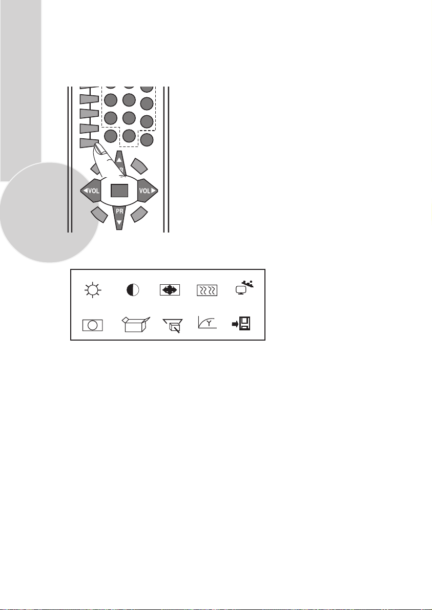
Features Menu (Purple button)
MENU
To select Features menu press
the menu button and using the
Program up and down buttons
OK
select Features.
You can also select the Features
menu directly by pressing the
purple button on the remote
control.
The Features menu allows you
to set up the following:
CHILD LOCK
CLOCK
TIMER
BACKROUND
LANGUAGE
Use the Program up and down
buttons to select the feature you
wish to change and use Volume
up and down buttons to adjust
this feature.
You can change the picture type whilst
watching the TV using the picture Smart
control.
Press the picture Smart control
page through the different picture
P-
types and select the one you want:
SOFT, NATURAL, RICH or USER.
to
CHILD LOCK
CLOCK
TMER
BACKGROUND
LANGUAGE
FEATURES
OFF
03 14
ON
Page 16
Child Lock:
Using the Child
Lock, you can lock any Program
you want so that adult channels
can not be watched by children.
You can cancel child lock any time
you want. To cancel Child Lock,
select Child Lock as OFF when
you are watching that program.
Clock:
Use the numeric buttons
to set the real time.
Note:
If you enter any channel
with teletext transmission, clock
will automatically set to real time.
Background:
You can adjust the
menu background as ON or OFF.
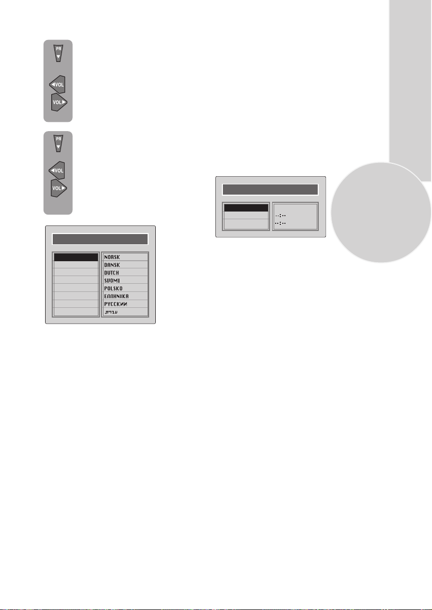
LANGUAGE
Language:
You can select one of the 16
languages by pressing OK button in the
language selection.
Timer:
Use Program up and down
buttons to select Timer in the features
menu. Using the Timer fuction, you can
switch to a specific programme at a preprogrammed time or you can turn your TV
off at the time you want your TV to be
turned off.
Press OK to access the Timer menu.
TIMER
ON TIMER
OFF TIMER
P 00PROGRAM NO
15
ENGLISH
DEUTSCH
FRANCAIS
ITALIANO
ESPANOL
PORTUGESA
TRKE
SVENSKA
On Timer:
Use the numeric buttons to set
the time that you want your TV to be turned
on (TV should be on stand-by mode).
Off Timer:
Use the numeric buttons to set
the time that you want your TV to be turned
off (Stand-by mode).
Program No:
Use the numeric buttons to
set the programme number that will be
shown when you set the On Time.
Page 17
Using Teletext
16
Teletext is an information system that displays
text on your TV screen. Using the teletext
control buttons you can view pages of
information that are listed in the teletext
index.
Please Note
No on screen display is available in text mode.
The contrast, brightness and colour cannot be
changed but the volume control is still
available.
To enter Text mode
Please Note
Make sure the TV channel you are watching
transmits teletext. If not NO TEXT sign will
be shown on the screen.
Press the button. The text
page will appear, normally the index
TV/TX
page.
TV/TEXT
To exit Text mode
Press the button. The TV
will return to the channel you were
TV/TX
watching.
TV/TXT
To select a page of text
Find the number of the page in the
index and enter it using the
0
Numeric
the page will appear in the top left
9
buttons. The number of
hand corner of the screen.
The page counter will search for your
page. When it finds it, the page will
be displayed.
To move to the next page of text
press the button.
Program up
To move to the previous page press
Program down
the button.
P100
To return to the index page press the
P100
button.
TV/text mix
To view a page of text whilst
MIX
watching a TV programme press
the
MIX
button. The text will be
superimposed over the TV
programme.
MIX
Press the
button again to return
MIX
to the text page.
Page search whilst watching TV
In Text mode press theUpdate
UPDATE
button. The TV will return to TV
mode with the text page number in
the top left hand corner of the
screen.
0
Enter the page number you want
using the buttons.
9
Numeric
The top line of the text page will
appear whilst the text searches for
your page. When the page is found
the number will remain in the top
left hand corner of the screen.
Press the button to view
UPDATE
Update
your selected page of text.
Double height text
If you have difficulty reading the
text on the TV you can double the
height of the text.
Press the button.
Double height
The top half of the page will be
displayed in double height text.
DOUBLE
Press the button
Double height
again. The bottom half of the page
will be displayed in double height
text.
DOUBLE
Press the button
Double height
again to return to the full page.
Page 18

Page Stop
If the page of text you have selected
HOLD
contains sub pages, these sub pages
will automatically be displayed in
order with a delay to allow you to
read the page.
To stop the move to the next sub
page press the STOP button. STOP
will appear in the top left hand
corner.
HOLD
To continue moving through the sub
pages press the STOP button again.
To select a sub page
If the page of text you are viewing
contains sub pages, the number of
the sub page you are on and the total
number of sub pages is displayed on
the right of the screen i.e. 1/7.
To select a sub page press the
SUB
SUB button. Press green button
to select next sub-page or prees
red button to select previous
sub-page.
Enter the number of the sub page,
5
using the Numeric buttons in the
format S0001 for sub page 1.
To reveal information
Press the Rev button to reveal
REVEAL
concealed information (quiz
answers etc.).
REVEAL
Press the Rev button again to
conceal the information again.
Clock
Press the Sub button, whilst
watching a TV program , to
SUB
display the time.
Fast text
At the bottom of the teletext screen is a row
of subject headings in red, green yellow and
blue.
The remote control has a row of coloured
buttons corresponding to the row of
coloured subjects on the screen.
Pressing one of the coloured buttons will
take you directly to the page
corresponding to the subject heading.
17
The teletext will search for the sub
page. This may take some time. To
return to the TV whilst the teletext
is searching press the Update
button.
When the page number is found it
will appear in the top left hand
corner of the screen.
UPDATE
Press the Update button again to
view the text page.
Page 19

Connecting external
equipment
You can connect a wide range of audio and
video equipment to your TV.
18
Connecting a video
recorder
Via SCART
Make sure the TV and video recorder are
both switched off.
Plug one end of the SCART lead (not
supplied) into the back of the video recorder
and the other end into one of the SCART
sockets on the back of the TV.
Switch on the video recorder and the TV.
Press the AV button on the remote
AV
control to select AV1 to correspond
with the SCART socket you are using
on the back of the TV.
Please note:
You can connect a RGB external equipment
via Scart. It is necessary to you use full Scart
cable for this purpose.
Select the video outputs of external device
by using its menu to RGB if it’s avaible.
Via RCA lead (optional)
Make sure the TV and video recorder are
both switched off.
Plug one end of the RCA lead into the video
and audio out sockets on the back of the
video recorder and plug the other end into
the video and audio in sockets of the TV.
If the sound is in mono use the Audio Input
L. In the SOUND menu select MONO.
Page 20
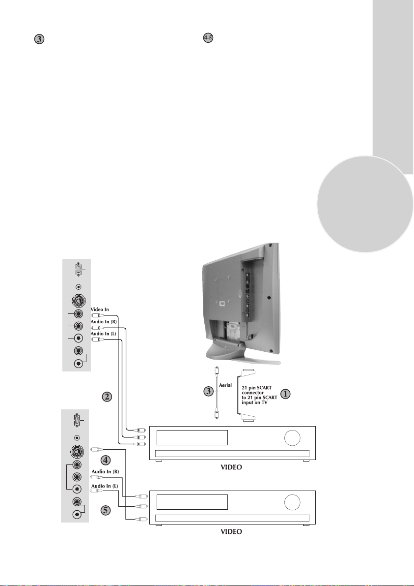
Via aerial socket
Make sure the TV and video recorder are
both switched off.
Unplug the aerial lead form the TV and plug
it into the aerial socket on the video
recorder (if fitted).
Plug a coaxial plug into the RF out socket on
the rear of the video recorder and plug the
other end into the aerial socket of the TV.
Switch on the video recorder and the TV.
If your video recorder has a test signal, switch
it on. (Refer to the video recorder user guide).
See ‘Tuning the TV’ and carry out the tuning
procedure for the video recorder test signal.
Select a programme number 0.
DC 12V VGA
AVS
Via RCA lead and S-Video socket
You can also connect it through the
S-Video socket of the TV.
Plug the S-Video plug into the S-Video
socket and the audio leads into the audio
sockets.
19
AV3
AVS
AV3
AUDIO OUT
AUDIO OUT
L R VIDEOL R S-VHS
DC 12V VGA
S-Video In
L R VIDEOL R S-VHS
Page 21
20
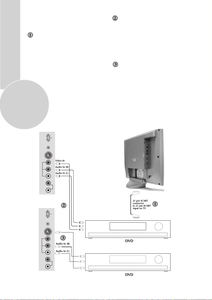
Connecting a DVD
player
Via SCART
Make sure the TV and DVD player are both
switched off.
Plug one end of the SCART lead (not
supplied) into the back of the DVD player
and the other end into the SCART
socket on the back of the TV.
Switch on the DVD and the TV.
DC 12V VGA
AVS
Via RCA lead
Make sure the TV and DVD player are both
switched off.
Plug one end of the RCA lead into the video
and audio out sockets on the back of the
DVD player and plug the other end into the
video and audio in sockets of the TV.
Via RCA lead and S-Video socket
You can also connect it through the
S-Video socket of the TV.
Plug the S-Video plug into the S-Video
socket and the audio leads into the audio
sockets.
AV3
AVS
AV3
AUDIO OUT
AUDIO OUT
L R VIDEOL R S-VHS
DC 12V VGA
S-Video In
L R VIDEOL R S-VHS
Page 22
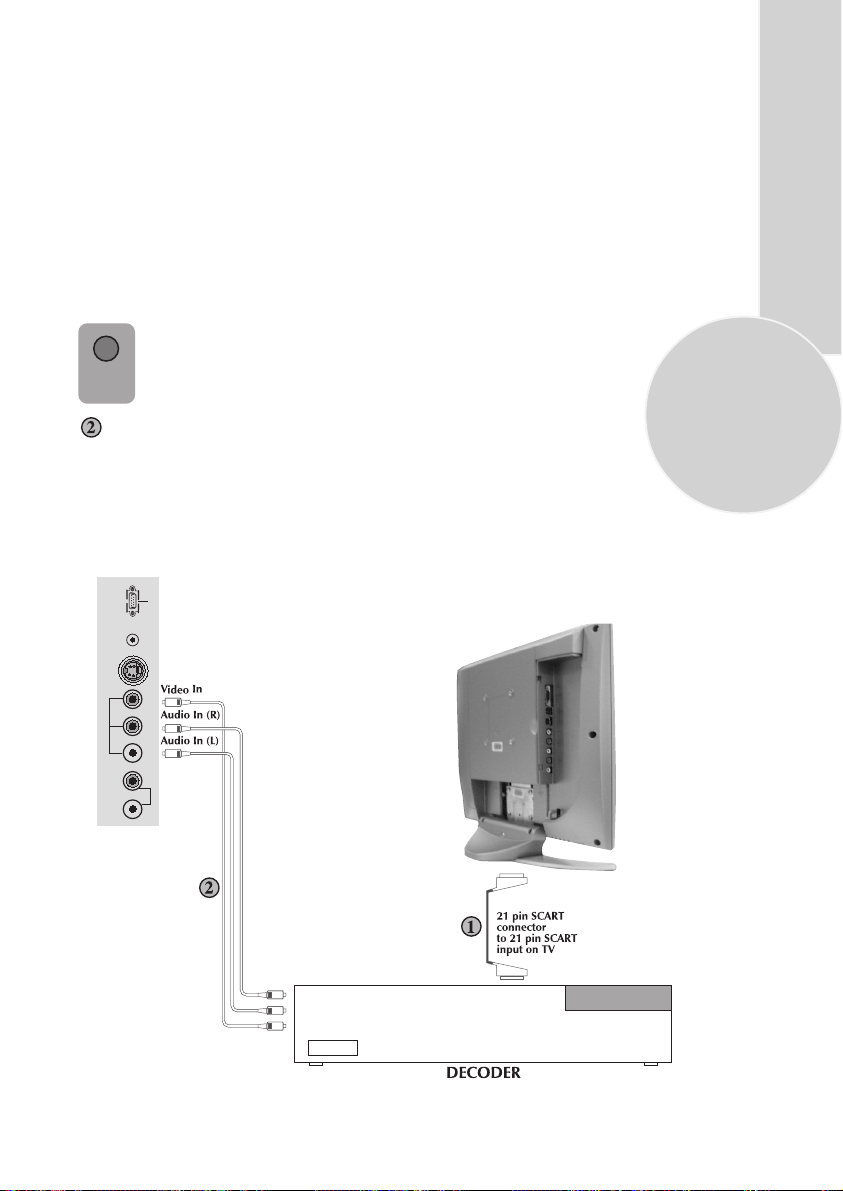
Connecting a decoder
Via SCART
Make sure the TV and decoder are both
switched off.
Plug one end of the SCART lead (not
supplied) into the back of the decoder and the
other end into the SCART
on the back of the TV.
Switch on the decoder and the TV.
Press the AV button on the remote
AV
control to select AV1.
Via RCA lead
Make sure the TV and decoder are both
switched off.
Note: For Decoder connection Via RCA
lead your Decoder device should have the
tuner built in.
DC 12V VGA
AVS
Plug one end of the RCA lead into the video
and audio out sockets on the back of the
decoder and plug the other end into the video
and audio in sockets on
the TV.
21
AV3
L R VIDEOL R S-VHS
AUDIO OUT
Page 23
3
INTRODUCTION
Because your 15”LCD-TV equipment is provided with VGA inputs, it may be used as a PC
monitor as well. (Pug&Play)
22
HOLD
SUB
UPDATE
MIX
TV/PC
TV/TX
PP
4
7
AV
OK
5
8
0
MENU
16:9
6
9
-/--
To enter the I.CD-TV in to the monitor (PC) mode, the “MIX(TVPC)” button on your remote control is used. Each time the
“MIX(TV/PC)” button is presed, operation changes from the PC
mode, press the “MIX” button again. In addition, you may relurn to
the TV mode by selecting the “TV SELECTION” option from the
monitor menu alternatively.
Note 1: When the system is in the monitor mode, the sound from
the TV channel selected may be heard from the speakers. When you
enter this mode, the sound control buttons on the remote control.
( “ VOL ”/“VOL “ MUTE) become functional
Note 2: When the system is in the monitor mode, the STANDBY
button is operational. Upon exit from STANDBY, the system starts
up in the TV mode again.
PC Mode Menu Structure
After chaning to the PC mode, you
may acces the monitor menus by
pressing the “MENU” button on
Entering the PC Mode
‹
ETC
the front panel of the system
To browse in the menus, you may use the“PR“/“PR“ buttons and Vol+ or Vol- buttons
to select the type of adjustment you wish to make. Once you make your selection, you may set
the desired adjustment value using the “PR“/“PR“ buttons.
BRIGHTNESS
After entering the Brightness Menu using the “VOL”/“VOL“ buttons, you may set the
brightness value of the monitor to the desired level by using the “PR“/“PR“ buttons.
CONTRAST
After entering the Contrast Menu using the “VOL”/“VOL“ buttons, you may set the
contrast value of the monitor to the desired level by using the “PR“/“PR“ buttons.
POSITION
After entering the Position Menu using the “VOL”/“VOL“ buttons, you may set the
geometrical adjustment value of the monitor to the desired level by using the“PR“/“PR“
buttons.
H-POSITION : Horizontal position adjustment
V-POSITION : Vertical position adjustment
IMAGE
After entering the Image Menu using the “VOL”/“VOL“ buttons, you may set the phase
adjustment value of the monitor to the desired level by using the “PR“/“PR“ buttons
PHASE : ADC sampling phase adjustment
CLOCK : ADC clock count Per line
Page 24

AUTO CONFIG : Allows the entry of optimum geometrical adjustments based on the input mode
INFORMATION : Displays the input mode information on the screen.
MISCELLANEOUS
You may enter the factory default settings, Menu position and duration on the screen, resolution
settings etc. by selecting the MISCELLANEOUS option.
FACTORY RESET : Loads the factory default settings
OSD TIMEOUT : The on-screen timeout may be adjusted to a value between
5 - 60 seconds.
OSD POSITION : Used for adjusting the OSD Horizontal and Vertical position
NATIVE MODE : Displays the input cursor in its actual resolution
TV SELECTION : To change from Monitor mode to TV mode
GAMMA : Correction of linear RGB data to compensate for non-linear response of TFT display.
MOIRE :
another.
SAVE : Stores the settings entered.
NOTE: The user can store the geometrical adjustments (H-Position, V-Position) entered for 6
different input graphic modes. When the Autoconfig is performed, the settings provided for that
mode are stored, therefore, activating the Autoconfig function each time the mode is changed, is not
necessary. When the user stores the settings for a 7th mode, the first mode stored will be erased
Warning Messages
1. No SYNC: The VGA input code (resolution) is missing. The "NO SYNC" message appears on
the display. The message stays on the screen for 30 seconds and if no other VGA input signal that
is supported by the system is not provided within that period, the system will go to "POWER
SAVING" mode in order to protect the LCD panel. In this mode, the display will turn off, but the
sound from the selected tuner channel will be audible
2. Input Not Supported: The input code (resolution) is not a supported graphics mode. The message
"INPUT NOT SUPPORTED" appears on the display. The message stays on the screen until a
supported graphic input code is received.
Correction of distortions giving an image of the picture lines superimposed over one
Input Graphic Modes Supported (progressive non-interlaced)
640 x 400 x 56 Hz
640 x 480 x 60 Hz
640 x 480 x 69 Hz
640 x 480 x 72 Hz
640 x 480 x 75 Hz
640 x 350 x 70 Hz
640 x 480 x 66 Hz (MAC)
640 x 480 x 85 Hz
720 x 400 x 70 Hz
720 x 400 x 85 Hz
800 x 600 x 56 Hz
800 x 600 x 60 Hz
800 x 600 x 72 Hz
800 x 600 x 75 Hz
800 x 600 x 85 Hz
832 x 624 x 75 Hz
1024 x 768 x 60 Hz
1024 x 768 x 70 Hz
1024 x 768 x 75 Hz
1024 x 768 x 85 Hz
Important Warning:
1. When the system changes from TV mode to VGA mode for the first time, the sound from
the speakers is muted, but available through the ear-phones
2. When a particular VGA mode is displayed for the first time, selecting the
"Autoconfiguration" option may be necessary. The position adjustment as well as the HPosition and V-Position fine adjustments must be entered and the values "saved (stored)"
3. When the signal is cut off, depending on the VGA power-saving standard, the message
"NO SIGNAL" is displayed on the screen for 30 seconds. At the end of this period, the
system turns off, providing an energy saving of 30 watts.
23
Page 25

24
Connecting TV with video and satellite/digital
receiver
Satellite/digital receiver Video Rear of TV
Arial out
Arial in
TV
Scart socket
Video
Scart socket
Arial out
Arial in
Scart socket
Arial
socket
Scart 1
Connecting TV with camcorder
AV1
DC 12V VGA
S-Video In
AVS
AV3
L R VIDEOL R S-VHS
AUDIO OUT
Camcorder
Connecting TV games and computer
AV1
DC 12V VGA
S-Video In
AVS
AV3
L R VIDEOL R S-VHS
AUDIO OUT
S-Video TV Game Player
Page 26

Help and service tips
The TV does not work
Make sure it is plugged into the mains supply
and switched on.
Poor picture
• Is the aerial plugged in?
• If you are using a set top aerial is it
properly aligned for the best signal.
• Make sure the aerial is not to close to
neon lights, loudspeakers etc.
•Try changing the direction of the outdoor
aerial. High buildings and mountains can
cause ghost pictures or double images.
• The picture quality may be reduced by
connecting two external sources at once.
Disconnect one of the sources.
• Adjust the fine tuning.
No picture
• Is the aerial plugged in properly?
• Is the aerial lead damaged?
• Are all the plugs in the aerial lead fitted
correctly?
• Have you pressed the correct buttons on
the remote control?
Remember…
For
please
television
queries,
ring
the
helpline…
operation
No sound
• Is the sound muted? Press the Mute
button.
• Is the volume turned down?
• Are there headphones connected?
Sound coming from only one
speaker
• Is the balance set to one side? See the
sound menu.
• If you have external speakers, has one of
them become disconnected.
No response to the remote control
•Try changing the batteries.
• Is there an obstruction between the
remote control and the sensor on the TV.
If nothing works
If you have tried the above solutions and none
seem to work, try switching the unit off and
on again.
If this does not work contact your supplier or
TV repair technician. Never attempt to
repair a defective TV yourself.
25
F
or
UK
o
n
ly
Page 27

Technical specifications table
26
Picture tube
size/typee
Screen size
Visible
screen size
Sound Output
(%10 THD)
Power
consumption
Stand by
Power
consumption
15”
4:3
38 cm
304,15 (H) x 228,1 (V)mm
2x2 W
45W (max)
2,5 W
General technical specifications
Power Supply
DC: ................................................... 12V-5A
Number of preset programmes ......... 100
RF Aerial input .................................... 75
Speaker empedance ...........................
Sound Systems...................................... Mono/Stereo/NICAM
Batteries ............................................ 2x AAA
Receiving channels ............................... VHF (Band I Channels 2-4)
............................................................. VHF (Band III Channels 5-12)
............................................................... UHF (Channels 21-69)
.............................................................. Cable TV (S1-S20/S21-S41)
ohm (unbalanced)
8 ohm
Page 28

Page 29

Page 30

Page 31

Page 32

Page 33

Page 34

Page 35

Page 36

Page 37

Page 38

Page 39

Page 40

Page 41

Page 42

Page 43

Page 44

Page 45

Page 46

Page 47

Page 48

Page 49

Page 50

Page 51

Page 52

Page 53

Page 54

Page 55

Page 56

Page 57

Page 58

Page 59

Page 60

Page 61

Page 62

Page 63

Page 64

Page 65

Page 66

Page 67

Page 68

Page 69

Page 70

Page 71

Page 72

654321
+3.3V+5V
L400
FERRIT BEAD
R401
3
22R
D
R418
C443
0.1uF
0.1uF
Y_IN
C_IN
Vin1
C445
C447
0.1uF
Vin2
C444
0.1uF
C446
0.1uF
Vin
C448
0.1uF
SC1_FBL
R430
47K
SC2_St
SC1_St
SCL5V
SDA5V
/RESET
/STDBY
13
12
3
5
1
2
6
7
100R
R419
100R
R420 100R
R421
R422 100R
R436
4.7K
GND
Z1
Z0
Y1
Y0
X1
X0
INH
VEE
C438
47pF
GND
C439
47pF
GND
100R
U401
HEF4053BT
16
VDD
VSS
8
R410
47K
C400 0.1uF
C401 0.1uF
C402
C440
C403
47pF
GND
C437
47pF
C404
GND
C434
47pF
GND
C441
2.2uF
GND GND
4
Z
15
Y
14
X
11
A
10
B
9
C
12Q402
C449
220pF
0.1uF
0.1uF
0.1uF
C442
0.1uF
CVBS_Out
C409
0.1uF
C410
0.1uF
C411
0.1uF
3
BC848B
GND
R412
10K
Vin
Vin2
SC2_St
SC1_St
SCL5V
SDA5V
/RESET
/STDBY
SC1_FBL
Y_IN
C_IN
Vin1
+12V
L410
FERRIT BEAD
SC_B
R437
2.2K
GND
SC_B
SC_G
SC_R
C450
0.1UF
R431
47K
R432
47K
R433
47K
R434
47K
R435
47K
SC_G
SC_R
C
GND
Vo
R406
75R
R106
75R
R403
75R
Q401
BC848B
2
R4041KR405
R408
220R
C412
22uF
10V
R402
12K
GND
1
22K
GNDGND
C408
10uF C419
10V
GND
C436
C422 3.3pF
0.1uF
GND
C423
GND
C435
+
22uF
0.047uF
C413
0.1uF
3.3pF
C420
10uF
10V
C414
0.1uF
C418
47pF
GND
C421
0.047uF
SCL
SDA
X400
20.25 MHz
C415
0.1uF
GND
GND
C416
220pF
9
10
VSUPCAP
29
VSUPA26VSUPD
VSUPLLC
36
VSUPY
C424
220pF
45
VSUPC
52
VSUPSY
INTLC
MSY/HS
FSY/HC
FPDAT
CLK20
FFRSTW
FFWE
VPC3230D
80
LLC2
LLC1
AVO
CLK5
FFOE
FFRE
FFIE
U400
C7
C6
C5
C4
C3
C2
C1
C0
Y7
Y6
Y5
Y4
Y3
Y2
Y1
Y0
VS
C417
220pF
76
69
59
8
NC
61
NC
VSUPF
VSTBY
VSUPAI
70
VOUT
72
VIN1
71
CIN
73
VIN2
74
VIN3
75
VIN4
79
FB1IN
1
B1/CB1IN
2
G1/Y1IN
3
R1/CR1IN
4
B2/CB2IN
5
G2/Y2IN
6
R2/CR2IN
78
VREF
17
VGAV
66
VRT
18
YCOEQ
15
RESQ
13
SCL
14
SDA
63
XTAL2
62
XTAL1
67
I2CSEL
16
TEST
ASGF7ASGF64GNDD11GNDCAP12GNDPA25GNDLLC30GNDY35GNDC46GNDSY51GNDF65ISGND68GNDAI77AISGND
GND
C425
220pF
VDD3
C432
0.1uF
GND
VCLK
YUV[0..7]
C433
22uF
10V
6
7
8
6
7
8
C429
0.1uF
YUV7
YUV6
YUV5
YUV4
YUV3
YUV2
YUV1
YUV0
C430
0.1uF
C431
0.1uF
YUV[0..7]
C426
0.1uF
41
42
43
44
47
48
49
50
31
Y7
Y6
32
Y5
33
Y4
34
Y3
37
Y2
38
Y1
39
Y0
40
27
28
53
57
GND
54
R415
220R
R414
220R
GND
C455
47pF
C454
220pF
56
55
58
60
24
23
22
21
20
19
C428
0.1uF
0.1uF
47R
R400
RN401
4 5
3
2
1
RN400
4 5
47R
3
2
1
47R
O_HS
O_VS
L401
FERRIT BEADC427
D
C
OSD_FBL
OSD_B
OSD_G
B
OSD_R
/RESET
SCL
SDA
C405
0.1uF
C406
0.1uF
C407
0.1uF
B
Proje = 15'' LCD TV
Kod= X60.190-03
Schematic= VIDEO DECODER
A
A
Beko Elektronik A.S.
Size
Document Number
Title
C
2. Video Decoder
Control
Date 24-Sep-2003 Sheet 4
1 2 3 4 5 6
of
Rev
A
9
Page 73

654321
R200
C200
C201
C202
GND
GND
GND
GND
0.1uF
LVDS_EN
C204
0.1uF
C209
0.1uF
C207
0.1uF
LVDS_EN
C210
0.1uF
C211
0.1uF
TX0-O
TX0+O
TX1-O
TX1+O
TX2-O
TX2+O
TX3-O
TX3+O
TXCK-O
TXCK+O
TX0-E
TX0+E
TX1-E
TX1+E
TX2-E
TX2+E
TX3-E
TX3+E
TXCK+E
C241
10uF
R2050R
R206 0R
R207 0R
R208 0R
R209 0R
R210 0R
R211
R213 0R
R214
C244
10uF
R218 0R
R219 0R
R220
R221
R222
R223
R224
0R
0RR212
0R
R215 0R
R216
R217 0R
C216
1N
0R
0R
0R
0R
0R
0R
C218
1N
RC200
DARED6
DARED0
DARED4
DARED3
DAGRN4
DAGRN5
DARED5
DAGRN1
DABLU7
1
DAGRN0
2
DABLU5
3
DABLU3
4 5
1
2
3
4 5
47R
DARED2
DARED1
DAGRN7
DAGRN6
RC202
1
2
3
4 5
47R
DAGRN2
DARED7
DAGRN3
DABLU6
RC205
47R
DABLU4
1
DABLU0
2
DABLU1
3
DABLU2
4 5
DAGRN[0..7]
DABLU[0..7]
DARED[0..7]
DABLU6
DABLU7
DABLU0
DABLU1
DABLU2
DABLU3
DABLU4
DABLU5
DARED6
DARED7
DARED0
DARED1
DARED2
DARED3
DARED4
DARED5
DAGRN6
DAGRN7
DAGRN0
DAGRN1
DAGRN2
DAGRN3
DAGRN4
DAGRN5
L201
47R
LVDS_EN
DARED[0..7]
DAGRN[0..7]
DABLU[0..7]
DBRED[0..7]
DBGRN[0..7]
DBBLU[0..7]
VS
HS
EN
DCLK
TP700
DARED[0..7]
DAGRN[0..7]
D
DABLU[0..7]
DBRED[0..7]
DBGRN[0..7]
DBBLU[0..7]
DVS
DHS
DEN
DCLK
LVDS_EN
C
DBRED[0..7]
DBGRN[0..7]
DBBLU[0..7]
B
DBRED6
DBRED7
DBRED0
DBRED1
DBRED2
DBRED3
DBRED4
DBRED5
DBGRN6
DBGRN7
DBGRN0
DBGRN1
DBGRN2
DBGRN3
DBGRN4
DBGRN5 TXCK-E
DBBLU6
DBBLU7
DBBLU0
DBBLU1
DBBLU2
DBBLU3
DBBLU4
DBBLU5
HS
1
VS
2
EN
3
4 5
DBRED6
1
DBRED4
2
DBRED3
3
DBRED2
4 5
DBGRN2
1
DBGRN1
2
DBRED7
3
DBGRN0
4 5
DBBLU7
1
DBBLU5
2
DBBLU3
3
DBBLU4
4 5
RC213
RC207
47R
RC209
47R
RC211
47R
DBRED1
DBRED0
DBGRN3
DBGRN6
DBGRN4
DBGRN5
DBRED5
DBBLU6
DBGRN7
DBBLU0
DBBLU1
DBBLU2
8
7
6
47R
AR6
8
AR0
7
AR4
6
AR3
RC201
1
2
3
4 5
47R
AG4
8
AG5
7
AR5
6
AG1
RC203
1
2
3
4 5
47R
AB7
8
AG0
7
AB5
6
AB3
RC206
47R
BR6
8
BR4
7
BR3
6
BR2
RC208
1
2
3
4 5
47R
BG2
8
BG1
7
BR7
6
BG0
RC210
1
2
3
4 5
47R
BB7
8
BB5
7
BB3
6
BB4
RC212
1
2
3
4 5
47R
U200
GND
AR6
AR7
AR0
AR1
AR2
AR3
AR4
AR5
AG6
AG7
AG0
AG1
AG2
AG3
AG4
AG5
AB6
AB7
AB0
AB1
AB2
AB3
AB4
AB5
DS90CF383MTD
50
2
51
52
54
55
56
3
8
10
4
6
7
11
12
14
16
18
15
19
20
22
23
24
25
27
28
30
31
TXIN27
TXIN5
TXIN0
TXIN1
TXIN2
TXIN3
TXIN4
TXIN6
TXIN10
TXIN11
TXIN7
TXIN8
TXIN9
TXIN12
TXIN13
TXIN14
TXIN16
TXIN17
TXIN15
TXIN18
TXIN19
TXIN20
TXIN21
TXIN22
TXIN23
TXIN24
TXIN25
TXIN26
TXCLKIN
AR2
8
AR1
7
AG7
6
AG6
AG2
8
AR7
7
AG3
6
AB6
AB4
8
AB0
7
AB1
6
AB2
TP702
TP701
TP703
DHS
DVS
DEN
DCLK
100pF
12
C217
R204
100R
GND
U201
BR6
BR7
BR0
BR1
BR2
BR3
BR4
BR5
BG6
BG7
BG0
BG1
BG2
BG3
BG4
BG5
BB6
BB7
BB0
BB1
BB2
BB3
BB4
BB5
DS90CF383MTD
50
2
51
52
54
55
56
3
8
10
4
6
7
11
12
14
16
18
15
19
20
22
23
24
25
27
28
30
31
TXIN27
TXIN5
TXIN0
TXIN1
TXIN2
TXIN3
TXIN4
TXIN6
TXIN10
TXIN11
TXIN7
TXIN8
TXIN9
TXIN12
TXIN13
TXIN14
TXIN16
TXIN17
TXIN15
TXIN18
TXIN19
TXIN20
TXIN21
TXIN22
TXIN23
TXIN24
TXIN25
TXIN26
TXCLKIN
BR1
8
BR0
7
BG3
6
BG6
BG4
8
BG5
7
BR5
6
BB6
BG7
8
BB0
7
BB1
6
BB2
DHS
DVS
DEN
DCLK
V1V
V1V
1K
0.1uF
0.1uF
9
17V26
A PIXELS
TXOUT0-
TXOUT1-
TXOUT2TXOUT3-
PLLVCC
PLLGND
PLLGND
GND
GND
GND
GND
GND
B PIXELS
TXOUT0-
TXOUT1-
TXOUT2-
TXOUT3-
PLLVCC
PLLGND
PLLGND
GND
GND
GND
GND
GND
C206
0.1uF
32
48
47
46
45
42
41
38
37
40
39
44
49
43
36
34
35
33
53
29
21
13
5
32
48
47
46
45
42
41
38
37
40
39
44
49
43
36
34
35
33
53
29
21
13
5
PWRDWN
R_FB
TXOUT0+
TXOUT1+
TXOUT2+
TXOUT3+
TXCLKOUT-
TXCLKOUT+
LVDSVCC
LVDSGND
LVDSGND
LVDSGND
C205
R202
0.1uF
1K
9
17V26
PWRDWN
R_FB
TXOUT0+
TXOUT1+
TXOUT2+
TXOUT3+
TXCLKOUT-
TXCLKOUT+
LVDSVCC
LVDSGND
LVDSGND
LVDSGND
GND
C219
0.1UF
C220
0.1UF
L200
FERRIT BEAD
L202
FERRIT BEAD
TP198
TP200
TP202
TP204
TP206
TP187
TP189
TP191
TP194
TP196
TP188
TP190
TP192
TP193
TP195
TP197
TP199
TP201
TP203
TP205
TP207
TP208
3.3V_LCD
3.3V_LCD
GND
GND
TX0-O
TX0+O
GND
TX1-O
TX1+O
GND
TX2-O
TX2+O
GND
TXCK-O
TXCK+O
GND
TX3-O
TX3+O
GND
TX0-E
TX0+E
GND
TX1-E
TX1+E
GND
TX2-E
TX2+E
TXCK-E
TXCK+E
TX3-E
TX3+E
GND
TP209
CN601
DF14 A-20P-1.25C
1
2
3
4
5
6
7
8
9
10
11
12
13
14
15
16
17
18
19
20
LVDS Connector
D
C
B
+3.3V
3.3V_LCD
C700
0.1uF
C705
1uF/10V
R703
47K
U701
1
2
3
4
8
S1
G1
S2
G2
TP223
D1
7
TESTPAD
D1
6
D2
5
D2
FDS9933A
GND
3
1
Q701
BC848B
2
GND
PNL_EN
PNL_EN
R701
12V_PANEL_EN
47K
A
C706
10uF
16V
C707
0.1uF
GNDGND
LVDS_EN
U203
MC33375ST-3.3T3
+5V
L204
FERRIT BEAD
C246
1uF/10V
VIN1VOUT
ON/OFF
2
3
GND
4
GND
TP224
TESTPAD
C247
22uF/10V
LVDS_3.3V
C212
0.1uF
Proje = 15'' LCD TV
Kod= X60.190-03
Schematic= DISPLAY
A
Beko Elektronik A.S.
Size
Document Number
Title
C
5. Display
Control
Date 24-Sep-2003 Sheet 7
1 2 3 4 5 6
of
Rev
A
9
Page 74

654321
R316 47R
R317 47R
R318 47R
VGA_5V
D300
SOT23
BAV70
D
R303
10K
1
2
3
4
R304
0R
GND
Opt. 128EDID Opt. 256EDID
TU100
TP103
CN103
R_in
Vin1
Vo2
R144
10K
TP105
TUNER_PHILIPS
1
NC
2
NC
3
+5V
4
SCL
5
SDA
6
AS
9
TP231
NC
10
NC
11
SIF
12
CVBS
13
5V
14
AF
GND15GND16GND17GND
18
V_GND
R119
Q100
470R
BC848B
R126
R116
75R
470R
V_GND V_GND
CN101
V2in
TP100 TP101
V_GND
A_GND A_GND
C110
1nF
TP104
C111
1nF
A_GND A_GND
C113
1nF
A_GND
R122
470R
TP106
C1161nF
A_GND
C118
1nF
TP110
R145
2.7K
V_GND
V_GND
SC1_St
V_GND
C190
100pF
TP116
R123
470R
10
12
14
16
18
20
R120
2
4
6
8
470R
R121
470R
A_GND
C114
1nF
2
4
6
8
10
12
14
16
18
20
SCART
CN104
1
3
5
7
9
11
13
15
17
19
21
C109
C112
1nF
1nF
TP230
R101
C100
0.1uF
R118
470R
CN100
S_VHS
2341
C132
4.7uF/6.3V
TP107
1
TP108
3
TP109
5
7
9
11
13
15
17
19
21
R100
100R
INDUCTOR
INDUCTOR
R140
330R
R141
330R
V_GND
V_GND
C101
220uF/16V
0.1uF
SCL5V
SDA5V
100R
V_GNDV_GND
C145
47uF/6.3V
V_GNDV_GND
Q101
BC848B
R107
75R
R117
470R
GND
V_GND
TP102
R114
1
75R
2
3
4
R115
75R
V_GND
C115
R108
R109
1nF
C117
1nF
75R
75R
75R
C131
4.7uF/6.3V
R102
100R
R103
100R
TP111
TP112
TP113
TP114
Vo2
C133
4.7uF/6.3V
C134
4.7uF/6.3V
A_GNDA_GND
SC_B
SC_G
SC_R
L120
L121
A_GND A_GND
V_GND
V_GND
V_GND
R110
C102
R113
75R
C_IN
Y_IN
Vin
C119
1nF
C120
1nF
L105
FERRIT BEAD
L100
FERRIT BEAD
C150
47pF
C151
0.33uF
C135
47uF/6.3V
C136
47uF/6.3V
+5V
L101
22uH
C160
2.2nF
C162
C170
KAP
A_GND
C166
2.2nF
X100 18.432MHz
C168
1.5pF
A_GND A_GND
+5V
L103
22uH
47pF
C165
2.2nF
A_GND
C167
1.5pF
A_GND
C153
47uF/6.3V
R159
4.7K
R160
4.7K
SCL5V
SDA5V
65
66
67
68
69
70
71
72
73
74
75
76
77
78
79
80
+5V
10uF/16V
A_GND
10uF/16V
C154
C104
0.1uF
AVSUP
AVSUP
ANA_IN1+
ANA_INANA_IN2+
TESTEN
XTAL_IN
XTAL_OUT
TP
AUD_CL_OUT
NC
NC
D_CTR_I/O_1
D_CTR_I/O_0
ADR_SEL
STBYQ
NC1I2C_CL2I2C_DA3I2S_CL4I2S_WS5I2S_DA_OUT
R104
100R
R105
100R
C155
LK101
LNK
62NC63NC64
C161
0.01uF
21
A_GNDA_GND A_GND
53
54
55
56
57
58NC59
60
AVSS61AVSS
ASG
SC2_IN_L
SC2_IN_R
SC1_IN_L
SC1_IN_R
VFERTOP
MONO_IN
U101
MSP 3410G
I2S_DA_IN1
ADR_DA8ADR_WS9ADR_CL10DVSUP11DVSUP12DVSUP13DVSS14DVSS15DVSS16I2S_DA_IN2
6
7
C121
C164
1nF
470pF
A_GND
LK102
21
LNK
GND A_GNDV_GND
52
ASG
49
50
51
SC3_IN_L
SC3_IN_R
C103
0.1uF
C169
3.3uF/16V
47
48
ASG
SC4_IN_L
SC4_IN_R
17NC18NC19NC20
C105
0.1uF
R151
220R
45NC46
AGNDC
C
B
CN102
L_in
A_GND A_GND
A
TP115
R111
75R
R112
75R
SC1_FBL
TP301
U300
VVCC
VCC
A0
A1
WP
A2
SCL
GND
SDA
M24CO2
TP303
1
VGND
+12V 8V
C152
0.33uF
C156
A_GND
42
43
44
NC41NC
AHVSS
AHVSS
CAPL_M
AHVSUP
CAPL_A
SC1_OUT_L
SC1_OUT_R
VREF1
SC2_OUT_L
SC2_OUT_R
DACM_SUB
DACM_L
DACM_R
VREF2
DACA_L
RESETQ21NC22NC23DACA_R
24
MSRES
GND
NC
NC
NC
C300
0.1uF
1
8V
8
7
6
5
3
10uF/16V
40
39
38
37
36
35
34
33
32
31
30
29
28
27
26
25
IN
L102
C122
1nF
C163
470pF
C157
10uF/16V
3
R301
47K
D301
5.6V
U102
MC78L08
A_GND
FERRIT BEAD
C158
10uF/16V
A_GND
A_GND
2
OUT
GND
GND
+5V
12
R129
1K
C106
0.1uF
BC858B
C128
1nF
R302
47K
VGA_SCL
D302
5.6V
TP214
1
R128
3.3K
Q102
C125
C123
1nF
A_GND
R130
1K
A_GND
1nF
A_GND
A_GND
TP300
VSDA
1
TP302
VSCL
8V
1
C124
1nF
C137
47uF/10V
4.7uF/6.3V
47uF/6.3V
A_GND
R146
2.2K
R147
2.2K
R155
1K
C146
47uF/10V
R156
1K
VGA_SDA
C139
R127
3.3K
C140
Q103
BC858B
A_GND
C188
1nF
A_GND
C189
1nF
A_GND
A_GND
A_GND
R153
10K
C126
1nF
8V
C127
1nF
R305100R
VS_VGA
HS_VGA
C138
4.7uF/6.3V
C171
1nF
C141
47uF/6.3V
A_GND
A_GND
C107
0.1uF
R306 100R
R310
510R
C175
1nF
C176
1nF
R131
330R
R154
10K
Q104
BC858B
R157
3.3K
R158
3.3K
Q105
BC858B
R133
330R
C186
0.22uF
TP117
TP118
TP119
TP120
GND
C177
1nF
+12V
1000uF/16V
1617
CN301
Shell
1
6
2
7
3
8
4
9
5
10
Shell
DB15 HD
GND
R307
100R
R308
100R
SC2_St
TP127
C172
1nF
C173
A_GND
TP126
1nF
8101012121414161618182020
2244668
1133557799111113131515171719
R132
TP132
100R
R134
TP133
100R
C142
47uF/6.3V
47uF/6.3V
C187
0.22uF
A_GND
C147
47uF/6.3V
TP138
MUTE
ON-OFF
TP139
TP140
C108
0.1uF
R162
10K
R163
47K
C148
47uF/6.3V
A_GND
C149
47uF/6.3V
C184
1000uF/16V
A_GND
A_GND
C185
1000uF/16V
R150
47K
C129
1nF
4
3
2
1
A_GND
Q106
BC858B
R142
330R
R143
330R
Q107
BC858B
A_GND
R309
510R
R152
0.47R
11
12
13
14
15
R125
C174
TP134
C178
1nF
C183
1nF
R124
470R
470R
CN112
HEADER 4
A_GND
TP121
TP122
TP123
TP124
TP125
D303
5.6V
R148
V_GND
2.7K
V_GND
R149
10K
TP128 TP129 TP130
V_GND
TP131
R137
R136
100R
330R
C179
C180
1nF
1nF
C143
TP137
R161
27K
Q109
BC848B
A_GND
L10810uH
L10910uH
C130
1nF
L11010uH
1
2
3
4
5
6
7
8
R139
100R
C181
1nF
TDA1517P
-INV1
SGND
SVRR
OUT1
PGND
OUT2
VP
M/SS
-INV29GND
TP141
TP142
TP143
R138
330R
C182
1nF
U103
C159
47uF/16V
R322
R323
75R
75R
GND GND
VGA_5V
C301
D306
C302
5.6V
CN110
Rout
A_GND
CN111
Lout
A_GND
47pF
47pF
R135
75R
19
Vo
1
1
GND
GND
GND
GND
GND
GND
GND
GND
CN109
3PIN
TP135
TP136
3
2
1
Vin2
CN105
SCART
21
21
V_GND
2
2
18
17
16
15
14
13
12
11
10
A_GND
Size
R324
75R
C
Document Number
R319 47R
R320 47R
Proje = 15'' LCD TV
Kod= X60.190-03
Schematic= INPUT CONNECTOR
Beko Elektronik A.S.
Title
1. Input Connectors
Control
Date 24-Sep-2003 Sheet 3
1 2 3 4 5 6
C303 0.01uF
C304 0.01uF
C305 0.01uF
C306 0.01uF
C307 0.01uF
C308 0.01uFR321 47R
RED+
RED-
GREEN+
GREEN-
BLUE+
BLUE-
VS
HS
D
C
B
A
Rev
A
of
9
Page 75

654321
GPIO[0..7]
D0
D1
D2
D3
D4
D5
D6
D7
C507
22uF
22uF/10V
C508
22uF
22uF/10V
SDA
SCL
GPIO[0..7]
LVDS_EN
2.5V_M+5V_M
3.3V_M
GND
TP217
TESTPAD
L502
FERRIT BEAD
C510
22uF
L503
FERRIT BEAD
GND
C513
22uF
TP218
TESTPAD
L504
FERRIT BEAD
C516
22uF
10V
GND
C517
0.1uF
GND
TP151
TP152
TP153
TP154
TP155
TP156
TP157
TP158
TP159
TP160
TP161
TP162
TP163
TP164
TP165
TP166 TP167
16 17
D3
15
14
13
12
11
10
9
A4
8
A5
7
A6
6
A15
5
WE A7
4
A12
3
A17 A14
2
A18 A16
1
HEADER2X16
Service connector_Flash programing
TP182
D2
TP181
18
D1D4
TP180
19
D0D5
TP179
20
A0D6
TP178
21
A1D7
TP177
22
A10A2
TP176
23
/PSENA3
TP175
24
A11
TP174
25
A9
TP173
26
A8
TP172
27
TP171
28
TP170
29
A13
TP169
30
TP168
31
32
CN503
/RST GND
Proje = 15'' LCD TV
Kod= X60.190-03
Schematic= MCU
C511
0.1uF
C514
0.1uF
U503
MC33375ST-2.5
L500
FERRIT BEAD
C504
22uF
22uF/10V
VIN1VOUT
2
ON/OFF
GND GND
D
U504
/PSEN
A0
A1
A2
A3
A4
A5
A6
A7
A8
A9
A10
A11
A12
A13
A14
A15
A16
A17
A18
WE
R521
1K
MC33375ST-3.3
2
20
19
18
17
16
15
14
13
3
2
31
1
12
4
5
11
10
6
9
30
32
7
D501
BAS40
8
7
6
5
TP503
ESDA
SDA
SCL
VIN1VOUT
ON/OFF
3.3V_M
A0
A1
A2
A3
A4
A5
A6
A7
A8
A9
A10
A11
A12
A13
A14
A15
A16
A17
A18
CE
OE
WE
D3.3V_M
U506
VCC
WP
SCK
SI
M24C16-RMN1T
1
TP216
TESTPAD
D3.3V_M
RN500 10K
1
2
3
4 5
1
2
3
4 5
Q500
2N7002
R500
3.3K
D3.3V_M
RN501 10K
D3.3V_M
R502
3.3V_M
3.3K
3
R501
1
1K
R504
2
4.7K
1
/RST
R526
1K
C525
4.7nF
GND
GND
Q501
C
KeypadConnector
B
3.3V_M
CN501
1
2
3
4
5
6
7
B7B
TP149
L509
FERRIT BEAD
SDA5V
SCL5V
SC2_St
SC2_St
/RESET
SC1_St
SC1_St
SC1_FBL
SC1_FBL
MSRES
L508FERRIT BEAD
TP144
TP150
LED_RED
IR
KEY_PMU
KEY_DRL
GND
TP146
TP148
R5191KR520
D2.5V_M
U500
RSTN
DS1818B
ResetCircuit
/STDBY
CVBS_Out
VCC
GND
/RESET
TP147
O_VS
O_HS
2N7002
+5V
R505
10K
3
Q503
BC848B
2
GND
1K
GND
C526
R525
0.1uF
2
47R
1
3
GND
R503
10K
Q502
BC848B
X500
6MHz
D2.5V_M
D500
BAS40-05
8
7
6
8
7
6
R527
C501
33pF
GND
C502
33pF
XTAL2
XTAL1
R507
10K
C500 0.1uF
HDATA0
HDATA1
HDATA2
HDATA3
HCLK/SCL
HFS/SDA
/IRQ
PNL_EN
HDATA0
HDATA1
HDATA2
HDATA3
HCLK/SCL
HFS/SDA
SDA
SCL
/SC1_FBL
PNL_EN
/BKLT_EN
/STDBY
/IRQ
IR
LED_RED
MUTE
KEY_PMU
KEY_DRL
/RAMRD
/RAMWR
TP215
17
18
19
20
21
22
23
24
44
45
46
47
48
49
50
62
34
35
36
37
38
39
40
41
28
29
30
31
51
52
33
25
32
53
54
55
58
59
60
61
A2.5V_M
26
P0.0
P0.1
P0.2
P0.3
P0.4
P0.5
P0.6
P0.7
P1.0
P1.1
P1.2
P1.3
P1.4
P1.5
P1.6
P1.7
P3.0
P3.1
P3.2
P3.3
P3.4
P3.5
P3.6
P3.7
P2.0
P2.1
P2.2
P2.3
P4.2
P4.3
P4.7/VS/OE
CVBS
HS/SC
RST
XTAL2
XTAL1
R
G
B
BLANK/COR
57
VDDA2.5
VDDA2.5
D3.3V_MD2.5V_M
68
14
VDD2.5
VDD2.5
43
1
VDD3.316VDD3.3
VDD3.3
VDD3.3
VSSA27VSSA56VSS15VSS42VSS69VSS
70
84
A19/P4.4
A18/P4.1
A17/P4.0
A16
A15
A14
A13
A12
A11
A10
PSEN
XROM
A9
A8
A7
A6
A5
A4
A3
A2
A1
A0
D7
D6
D5
D4
D3
D2
D1
D0
U501
63
64
66
65
67
71
73
72
79
83
77
75
74
76
78
80
82
2
3
5
4
6
8
10
12
11
9
7
81
13
SDA5550
HDATA[0..3]
A18
A17
A16
A15
A14
A13
A12
A11
A10
A9
A8
A7
A6
A5
A4
A3
A2
A1
A0
D7
D6
D5
D4
D3
D2
D1
D0
/PSEN
3.3V_M
D[0..7]
HDATA[0..3]
HCLK
HFS
/RAMRD
/RAMWR
A[0..18]
3.3V_M
20
A0
A0
19
A1
A1
18
A2
A2
17
A3
A3
16
A4
A4
15
A5
A5
14
A6
A6
13
A7
A7
3
A8
A8
2
A9
A9
31
A10
A10
1
A11
A11
12
A12
A12
4
A13
A13
11
A14
A14
7
A16
A15
10
A17
A16
30
A15
CS1
6
CS2
32
OE
5
WE
100R
C528
1UF/10V
+12V
TP186
GND
GND
GND
TP185
L106
FERRITE BEAD
C503
0.1uF
TP183
TP184
CN502
1
2
3
4
5
6
7
8
9
10
11
12
53398-1290
BacklightConnector
GPIO0
OSD_R
OSD_G
OSD_B
OSD_FBL
+5V
Q505
BC848B
R511
47R
R510
100R
R512
470R R515
GND
+5V
Q506
BC848B
R514
R513
100R
47R
470R R518
GND
Q507
BC848B
R517
47R
+5V
GND
470R
R516
100R
+5V_M
R508
GPIO0
R506
2.2K
10K
/BKLT_EN
R509
10K
A
3
1
Q504
BC848B
2
GND
BKLT_EN
GND
8
VCC
VSS
24
C506
0.1uF
U502
IO1
IO2
IO3
IO4
IO5
IO6
IO7
IO8
NC
K6T1008V2E-TB
L501
FERRIT BEAD
GND
21
D0
22
D1
23
D2
25
D3
26
D4
27
D5
28
D6
29
D7
9
TP501
ESCL
1
C505
22uF
22uF/10V
/IRQ
PNL_EN
3.3V_M
TP500
1
EVCC
GND
GND
GND
GND
GND
4
4
8
24
VSS
GND
GND
VCC
VSS
A0
A1
A2
SOT223
SOT223
C509
0.1uF
DQ0
DQ1
DQ2
DQ3
DQ4
DQ5
DQ6
DQ7
GPIO7
GPIO6
GPIO5
GPIO4
GPIO3
GPIO2
GPIO1
GPIO0
3
3
U505
29LV040
1
2
3
4
21
22
23
25
26
27
28
29
TP502
EVSS
GND
GND
1
C518
0.1uF
C512
0.1uF
C515
0.1uF
A2.5V_M
D2.5V_M
C519
0.1uF
D
D3.3V_M
C520
0.1uF
C
B
A
Beko Elektronik A.S.
Size
Document Number
Title
C
3. MCU
Control
Date 24-Sep-2003 Sheet 5
1 2 3 4 5 6
of
Rev
A
9
Page 76

654321
DVDD_3.3DVDD_2.5
C631
0.1uF
DVDD_3.3
GND
C632
0.1uF
GREEN+
GREEN-
AVDD_3.3
R600 10K
GND
YUV[0..7]
GPIO[0..7]
HDATA[0..3]
DDC_SCL
DDC_SDA
RED+
RED-
BLUE+
BLUE-
RXC+
RXCRX0+
RX0RX1+
RX1RX2+
RX2-
VCLK
HFS
HCLK
/IRQ
/RESET
D17
P17
F17
K17
D14
M17
DVDD_2.5
DVDD_2.5
DVDD_2.5
Analog Input
TMDS Receiver
PLL and DDS
Video Input
Host Interface
HDCP
DGND
DGND
DGND
H11
H10
H12
T17
DVDD_2.5
DVDD_2.5
DVDD_2.5
DVDD_2.5
DGND
DGND
DGND
DGND
J8
J9
H13
U14
U16
U11
DVDD_2.5
DVDD_2.5
DVDD_2.5
DGND
DGND
DGND
J10
J12
J11
U7
U4
DVDD_2.5U9DVDD_2.5
DVDD_2.5
gm5020
DGND
DGND
K9
J13
K8
D12
GND
A6
A7
A8
A9
A10
A11
B2
B6
B7
B8
B9
B11
C3
D3
E3
A2
A3
A4
B1
B3
B4
C4
C5
C7
C11
D4
D5
D7
D11
E4
F2
F4
G1
G3
H1
J1
J3
F3
G2
G4
H2
H3
J2
K3
E1
E2
D2
D1
C1
C2
A1
C6
D6
C8
D8
C9
D9
C10
D10
A5
B5
B10
H4
J4
K1
L2
F1
K2
L3
A12
B12
C12
A13
B13
C13
A14
B14
C14
G19
G18
L1
M1
M2
M3
M4
N1
P3
P4
R1
R2
P2
P1
R3
R4
T1
T2
N2
N3
U600
AVDD_2.5
AVDD_2.5
AVDD_2.5
AVDD_2.5
AVDD_2.5
AVDD_2.5
AVDD_3.3
AVDD_3.3
AVDD_3.3
AVDD_3.3
AVDD_3.3
AVDD_3.3
AVDD_3.3
AVDD_3.3
AVDD_3.3
AGND
AGND
AGND
AGND
AGND
AGND
AGND
AGND
AGND
AGND
AGND
AGND
AGND
AGND
AGND
PLLVDD_3.3
PLLVDD_3.3
PLLVDD_3.3
PLLVDD_3.3
PLLVDD_3.3
PLLVDD_3.3
PLLVDD_3.3
PLLGND
PLLGND
PLLGND
PLLGND
PLLGND
PLLGND
PLLGND
RED+
REDGREEN+
GREENBLUE+
BLUEADC_TEST
RXC+
RXCRX0+
RX0RX1+
RX1RX2+
RX2-
CLKOUT
VBUFC
REXT
XTAL
TCLK
VSYNC
HSYNC
ANTEST
VDACP
EXTCLK
VCLK
YUV7
YUV6
YUV5
YUV4
YUV3
YUV2
YUV1
YUV0
GPIO7/DOVL
GPIO6/DFSYNCn
GPIO5/TXD
GPIO4/RXD
GPIO3/T1
GPIO2
GPIO1/PWM1
GPIO0/PWM0
HDATA3
HDATA2
HDATA1
HDATA0
HFS/SDA
HCLK/SCL
IRQn
IRQINn
RESETn
SCAN_TEST
DDC_SCL
DDC_SDA
gm5020
BGA292
DVDD_2.5
DGND
H8
H9
AVDD_2.5
AVDD_3.3
GND
PVDD_3.3
GND
C645
REXT
YUV7
YUV6
YUV5
YUV4
YUV3
YUV2
YUV1
YUV0
GPIO7
GPIO6
GPIO5
GPIO4
GPIO3
GPIO2
GPIO1
GPIO0
HDATA3
HDATA2
HDATA1
HDATA0
ADC_TEST
CLKOUT
VBUFC
XTAL
TCLK
ANTEST
VDACP
EXTCLK
TP600
TP601
TP602
R601
1.00K
1%
VS
HS
YUV[0..7]
GPIO[0..7]
HDATA[0..3]
TP603
TP604
GND
0.1uF
N4
K4
DVDD_2.5
DVDD_2.5
DGND
DGND
DGND
DGND
K10
K12
K11
D16
D15
D13
DVDD_3.3
DVDD_3.3
DGND
DGNDL8DGNDL9DGND
K13
GND
J17
E17
G17
DVDD_3.3
DVDD_3.3
DVDD_3.3
DVDD_3.3
DGND
DGND
L10
L11
L12
R17
N17
L17
DVDD_3.3
DVDD_3.3
DVDD_3.3
DGND
DGNDM8DGNDM9DGND
L13
U15
U12
U10
U17
U13
DVDD_3.3
DVDD_3.3
DVDD_3.3
DVDD_3.3
DVDD_3.3
Display Port
Frame StoreInterface
DGND
DGND
DGND
DGNDN8DGND
M10
M11
M12
M13
L4
U8
U5
U6
T4
DVDD_3.3
DVDD_3.3
DVDD_3.3
DVDD_3.3
DVDD_3.3
DGND
DGNDN9DGND
DGND
N11
N13
N10
N12
G20
DCLK
F20
DHS
F19
DVS
DEN
DARED0
DARED1
DARED2
DARED3
DARED4
DARED5
DARED6
DARED7
DAGRN0
DAGRN1
DAGRN2
DAGRN3
DAGRN4
DAGRN5
DAGRN6
DAGRN7
DABLU0
DABLU1
DABLU2
DABLU3
DABLU4
DABLU5
DABLU6
DABLU7
DBRED0
DBRED1
DBRED2
DBRED3
DBRED4
DBRED5
DBRED6
DBRED7
DBGRN0
DBGRN1
DBGRN2
DBGRN3
DBGRN4
DBGRN5
DBGRN6
DBGRN7
DBBLU0
DBBLU1
DBBLU2
DBBLU3
DBBLU4
DBBLU5
DBBLU6
DBBLU7
FSDATA0
FSDATA1
FSDATA2
FSDATA3
FSDATA4
FSDATA5
FSDATA6
FSDATA7
FSDATA8
FSDATA9
FSDATA10
FSDATA11
FSDATA12
FSDATA13
FSDATA14
FSDATA15
FSDATA16
FSDATA17
FSDATA18
FSDATA19
FSDATA20
FSDATA21
FSDATA22
FSDATA23
FSDATA24
FSDATA25
FSDATA26
FSDATA27
FSDATA28
FSDATA29
FSDATA30
FSDATA31
FSDATA32
FSDATA33
FSDATA34
FSDATA35
FSDATA36
FSDATA37
FSDATA38
FSDATA39
FSDATA40
FSDATA41
FSDATA42
FSDATA43
FSDATA44
FSDATA45
FSDATA46
FSDATA47
FSADDR0
FSADDR1
FSADDR2
FSADDR3
FSADDR4
FSADDR5
FSADDR6
FSADDR7
FSADDR8
FSADDR9
FSADDR10
FSADDR11
FSADDR12
FSADDR13
FSCLK
FSCKE
FSRAS
FSCAS
FSWE
FSDQM0
FSDQM1
FSDQM2
FSDQM3
F18
K18
J20
J19
J18
H20
H19
H18
H17
M18
M19
M20
L18
L19
L20
K20
K19
R19
R20
P18
P19
P20
N18
N19
N20
B17
A17
C16
B16
A16
C15
B15
A15
B20
B19
A20
A19
C18
B18
A18
C17
E20
E19
E18
D20
D19
D18
C20
C19
V6
W6
Y6
V7
W7
Y7
V8
V9
W9
Y9
V10
W10
Y10
Y11
W11
V11
Y12
Y13
W13
V13
Y14
W14
V14
Y15
W15
V15
Y16
W16
V16
Y17
W17
V17
Y18
W18
V18
Y19
W19
Y20
W20
V19
V20
U18
U19
U20
T18
T19
T20
R18
Y5
W5
V5
Y4
W4
V4
Y3
W3
V3
Y2
W2
Y1
W1
V2
T3
U1
V1
U3
U2
W8
Y8
V12
W12
DARED0
DARED1
DARED2
DARED3
DARED4
DARED5
DARED6
DARED7
DAGRN0
DAGRN1
DAGRN2
DAGRN3
DAGRN4
DAGRN5
DAGRN6
DAGRN7
DABLU0
DABLU1
DABLU2
DABLU3
DABLU4
DABLU5
DABLU6
DABLU7
DBRED0
DBRED1
DBRED2
DBRED3
DBRED4
DBRED5
DBRED6
DBRED7
DBGRN0
DBGRN1
DBGRN2
DBGRN3
DBGRN4
DBGRN5
DBGRN6
DBGRN7
DBBLU0
DBBLU1
DBBLU2
DBBLU3
DBBLU4
DBBLU5
DBBLU6
DBBLU7
FSDATA0
FSDATA1
FSDATA2
FSDATA3
FSDATA4
FSDATA5
FSDATA6
FSDATA7
FSDATA8
FSDATA9
FSDATA10
FSDATA11
FSDATA12
FSDATA13
FSDATA14
FSDATA15
FSDATA16
FSDATA17
FSDATA18
FSDATA19
FSDATA20
FSDATA21
FSDATA22
FSDATA23
FSDATA24
FSDATA25
FSDATA26
FSDATA27
FSDATA28
FSDATA29
FSDATA30
FSDATA31
FSDATA32
FSDATA33
FSDATA34
FSDATA35
FSDATA36
FSDATA37
FSDATA38
FSDATA39
FSDATA40
FSDATA41
FSDATA42
FSDATA43
FSDATA44
FSDATA45
FSDATA46
FSDATA47
FSADDR0
FSADDR1
FSADDR2
FSADDR3
FSADDR4
FSADDR5
FSADDR6
FSADDR7
FSADDR8
FSADDR9
FSADDR10
FSADDR11
FSADDR12
FSADDR13
R605
DARED[0..7]
DAGRN[0..7]
DABLU[0..7]
DBRED[0..7]
DBGRN[0..7]DBGRN[0..7]
DBBLU[0..7]
FSDATA[0..47]
FSADDR[0..13]
FERRITE
Beko Elektronik A.S.
Size
Document Number
Date 24-Sep-2003 Sheet 6
Title
C
4. gm5020
Control
DCLK
DHS
DVS
DEN
DARED[0..7]
DAGRN[0..7]
DABLU[0..7]
DBRED[0..7]
DBGRN[0..7]
DBBLU[0..7]
FSDATA[0..47]
FSADDR[0..13]
FSCLK
FSCKE
FSRAS
FSCAS
FSWE
FSDQM0
FSDQM1
FSDQM2
FSDQM3
D
C
B
A
Rev
A
of
9
+3.3V
L600
FERRIT BEAD
C600
22uF
C605
0.1uF
C608
0.01uF
C611
220pF
C614
0.1uF
C617
0.1uF
C620
0.1uF
+2.5V
D
L601
FERRIT BEAD
C601
22uF
10V
C606
0.1uF
C609
0.01uF
C612
220pF
C615
0.1uF
C618
0.1uF
C621
0.1uF
C623
0.1uF
C624
0.1uF
C625
0.1uF
C626
0.1uF
C627
0.1uF
C628
0.1uF
C629
0.1uF
DVDD_2.5
C630
0.1uF
GND
C619
0.1uF
AVDD_3.3
C622
0.1uF
+3.3V
L602
FERRIT BEAD
C602
22uF
C607
0.1uF
C610
0.01uF
C613
220pF
C616
0.1uF
GND
C639
0.1uF
AVDD_2.5
C641
0.1uF
+2.5V
L603
FERRIT BEAD
C603
22uF
C633
0.1uF
C635
0.01uF
C637
220pF
GND
C640
0.1uF
PVDD_3.3
C642
0.1uF
+3.3V
L604
FERRIT BEAD
C
C604
22uF
C634
0.1uF
C636
0.01uF
C638
220pF
GND
B
C643
5pF
C644
5pF
X600
24MHz
XTAL
TCLK
R602
2.2K
GND
AVDD_3.3
A
Proje = 15'' LCD TV
Kod= X60.190-03
Schematic= GM5020
1 2 3 4 5 6
Page 77

+3.3V
22UH
L800
C800
22uF
C801
0.1uF
C802
0.1uF
+3.3V
3.3V1 3.3V2 3.3V3
C803
0.1uF
C804
220pF
C805
220pF
C806
0.1UF
22UH
L801
C807
22uF
C808
0.1uF
C810
0.1uF
C811
0.1uF
C812
220pF
C813
220pF
C814
0.1UF
+3.3V
22UH
L802
C815
22uF
C816
0.1uF
C817
0.1uF
C818
0.1uF
C819
0.1UF
C820
220pF
654321
C821
220pF
GND
D
FSCLK
FSDATA[0..47]
FSADDR[0..13]
R802 47R
R803 47R
R80447R
R80547R
R806
47R
47R
R807
FSADDR0
FSADDR1
FSADDR2
FSADDR3
FSADDR4
FSADDR5
FSADDR6
FSADDR7
FSADDR8
FSADDR9
FSADDR10
FSADDR11
FSDATA[0..47]
FSADDR[0..13]
FSCKE
FSRAS
FSCAS
FSWE
FSDQM0
FSDQM1
C
GND
GND
D
3.3V1
25
13
VCC1VCC
VCCQ7VCCQ
VSS
VSS50VSSQ4VSSQ10VSSQ41VSSQ
44
VCCQ38VCCQ
47
DQ0
DQ1
DQ2
DQ3
DQ4
DQ5
DQ6
DQ7
DQ8
DQ9
DQ10
DQ11
DQ12
DQ13
DQ14
DQ15
NC
K4S161622
FSADDR5
FSADDR6
2
FSDATA0
FSDATA1
3
FSDATA2
5
FSDATA3
6
FSDATA4
8
FSDATA5
9
FSDATA6
11
FSDATA7
12
FSDATA8
39
40
FSDATA9
FSDATA10
42
FSDATA11
43
FSDATA12
45
FSDATA13
46
FSDATA14
48
FSDATA15
49
FSADDR12
FSADDR11
FSADDR7
FSADDR13
37
U800
21
A0
22
A1
23
A2
24
A3
27
A4
28
A5
29
A6
30
A7
31
A8
32
A9
20
A10
19
A11
35
CLK
34
CKE
18
/CS
17
/RAS
16
/CAS
15
/WE
14
LDQM
36
UDQM
26
RN800
4 5
3
2
1
10K
RN801
4 5
3
2
1
10K
6
7
8
GND
+3.3V
6
7
8
C
GND
3.3V2
25
13
VCC1VCC
VCCQ7VCCQ
VSS
VSS50VSSQ4VSSQ10VSSQ41VSSQ
44
VCCQ38VCCQ
47
DQ0
DQ1
DQ2
DQ3
DQ4
DQ5
DQ6
DQ7
DQ8
DQ9
DQ10
DQ11
DQ12
DQ13
DQ14
DQ15
NC
K4S161622
FSDATA16
2
FSDATA17
3
FSDATA18
5
FSDATA19
6
FSDATA20
8
FSDATA21
9
FSDATA22
11
FSDATA23
12
FSDATA24
39
FSDATA25
40
FSDATA26
42
FSDATA27
43
FSDATA28
45
FSDATA29
46
FSDATA30
48
49
FSDATA31
37
B
U801
FSADDR0
FSADDR1
FSADDR2
FSADDR3
FSADDR4
FSADDR5
FSADDR6
FSADDR7
FSADDR8
FSADDR9
FSADDR10
FSADDR11
FSDQM2
FSDQM3
R808 47R
R809 47R
B
21
A0
22
A1
23
A2
24
A3
27
A4
28
A5
29
A6
30
A7
31
A8
32
A9
20
A10
19
A11
35
CLK
34
CKE
18
/CS
17
/RAS
16
/CAS
15
/WE
14
LDQM
36
UDQM
26
GND
3.3V3
25
13
VCC1VCC
VCCQ7VCCQ
VSS
VSS50VSSQ4VSSQ10VSSQ41VSSQ
44
VCCQ38VCCQ
47
GND
DQ0
DQ1
DQ2
DQ3
DQ4
DQ5
DQ6
DQ7
DQ8
DQ9
DQ10
DQ11
DQ12
DQ13
DQ14
DQ15
NC
K4S161622
FSDATA32
2
FSDATA33
3
5
FSDATA34
FSDATA35
6
FSDATA36
8
FSDATA37
9
FSDATA38
11
FSDATA39
12
FSDATA40
39
FSDATA41
40
FSDATA42
42
FSDATA43
43
FSDATA44
45
FSDATA45
46
FSDATA46
48
FSDATA47
49
Proje = 15'' LCD TV
37
Kod= X60.190-03
Schematic= FRAME STORE
A
Beko Elektronik A.S.
Size
Document Number
Title
C
6. Frame Store
Control
Date 24-Sep-2003 Sheet 8
of
Rev
A
9
U802
FSADDR0
FSADDR1
FSADDR2
FSADDR3
FSADDR4
FSADDR5
FSADDR6
FSADDR7
FSADDR8
FSADDR9
FSADDR10
FSADDR11
C809
47pF
R800
75R
A
GND
GND
21
A0
22
A1
23
A2
24
A3
27
A4
28
A5
29
A6
30
A7
31
A8
32
A9
20
A10
19
A11
35
CLK
34
CKE
18
/CS
17
/RAS
16
/CAS
15
/WE
14
LDQM
36
UDQM
26
1 2 3 4 5 6
Page 78

654321
CN900
POWER
Opt. Ext. Supply
D
C
+12V_IN
TP210
CN901
41792-2
Opt. Int. Supply
TP211
1
2
TP212
L902
FERRIT BEAD
L903
FERRIT BEAD
F900
+12V
5A
C900
EEUFC1V681
680uF/35V
+5V
C901
0.1uF
D900
MRA4003T3
+5V
D902
MRA4003T3
D901
MRA4003T3
U900
LM2596S-5.0
1
VIN
ON/OFF5VOUT
TO263-7
L901
FERRIT BEAD
GND
3
L900
FERRIT BEAD
FBK
ON-OFF
GND
BC848B
Q900
+5V_M
3
2
GND
C914
2.2uF
10V
TP219
TESTPAD
TP220
TESTPAD
8
D1
7
D1
6
D2
5
D2
R902
4.7K
R903
1
47K
1
2
3
4
U906
S1
G1
S2
G2
FDS9933A
+5V
GND
C915
47uF
10V
/STDBY
D
C
4
2
D903
1N5820
+
C903
C904
47uF
47uF/10V
+
47uF
47uF/10V
L905
PE-54040
33uH
R900
10K
2
1
R901
10K
LP3962ES-2.5
VIN
SD
TO263-5
LP3962ES-3.3V
2
VIN
1
SD
TO263-5
GND3ERROR
5
GND
C902
EEUFC1V331
330uF/35V
VOUT
U901
GND3ERROR
U902
5
VOUT
1.5A Max
1.5A Max
L906
FERRIT BEAD
C908
0.1uF
L907
FERRIT BEAD
+2.5V
TP221
TESTPAD
4
+
C909
47uF
47uF/10V
+3.3V
TP222
TESTPAD
4
+
C910
47uF
47uF/10V
GND
B
B
Proje = 15'' LCD TV
Kod= X60.190-03
Schematic= POWER
A
A
Beko Elektronik A.S.
Rev
A
9
C
Title
24-Sep-2003
7. Power
Control
Sheet 9
Size
Document Number
Date
1 2 3 4 5 6
of
Page 79

Page 80

 Loading...