

Page 1
FILE NO. 810-200765GR
SERVICE MANUAL
15-inch Diagonal LCD TV/DVD
COMBINATION
15DLV77C
The above model is classified as a green product (*1), as indicated by the underlined serial number.
This Service Manual describes replacement parts for the green product. When repairing this green
product, use the part(s) described in this manual and lead-free solder (*2).
For(*1) and (*2), see the next page.
©2007 Toshiba Corporation
DOCUMENT CREATED IN JAPAN, June, 2007 GREEN
Page 2

(*1) GREEN PRODUCT PROCUREMENT
The EC is actively promoting the WEEE & RoHS Directives that define standards for recycling
and reuse of Waste Electrical and Electronic Equipment and for the Restriction of the use of
certain Hazardous Substances. From July 1, 2006, the RoHS Directive will prohibit any
marketing of new products containing the restricted substances.
Increasing attention is given to issues related to the global environmental. Toshiba Corporation
recognizes environmental protection as a key management tasks, and is doing its utmost to
enhance and improve the quality and scope of its environmental activities. In line with this,
Toshiba proactively promotes Green Procurement, and seeks to purchase and use products,
parts and materials that have low environmental impacts.
Green procurement of parts is not only confined to manufacture. The same green parts used in
manufacture must also be used as replacement parts.
(*2) LEAD-FREE SOLDER
This product is manufactured using lead-free solder as a part of a movement within the consumer
products industry at large to be environmentally responsible. Lead-free solder must be used in
the servicing and repair of this product.
WARNING
This product is manufactured using lead free solder.
DO NOT USE LEAD BASED SOLDER TO REPAIR THIS PRODUCT !
The melting temperature of lead-free solder is higher than that of leaded solder by 86°F to 104°F
(30°C to 40°C). Use of a soldering iron designed for lead-based solders to repair product made
with lead-free solder may result in damage to the component and or PCB being soldered. Great
care should be made to ensure high-quality soldering when servicing this product ⎯ especially
when soldering large components, through-hole pins, and on PCBs ⎯ as the level of heat
required to melt lead-free solder is high.
Page 3
ColorStream® is a registered trademark of Toshiba America Consumer Products, L.L.C.
is a trademark of Toshiba America Consumer Products, L.L.C.
J5X00401A SH 07/05
N
Printed in Thailand
15-inch Diagonal LCD TV/DVD
*
COMBINATION
15DLV77C
OWNER’S MANUAL
©2007 Toshiba Corporation
Before operating the unit, please read this manual thoroughly.
*Screen size is approximate.
Introduction
Connections
Basic setup
TV operation
Basic playback
Advanced playback
Function setup
Others
2
14
21
23
29
32
44
51
Introduction
The lightning ash with arrowhead symbol, within an equilateral
CAUTION
RISK OF ELECTRIC SHOCK
DO NOT OPEN
CAUTION:
TO REDUCE THE RISK OF ELECTRIC
SHOCK, DO NOT REMOVE COVER
(OR BACK). NO USER-SERVICEABLE
PARTS INSIDE. REFER SERVICING TO
QUALIFIED SERVICE PERSONNEL.
WARNING: TO PREVENT FIRE OR SHOCK HAZARD, DO NOT EXPOSE THIS APPLIANCE TO RAIN
CAUTION : TO PREVENT ELECTRIC SHOCK DO NOT USE THIS POLARIZED PLUG WITH AN
WARNING: Handling the cord on this product or cords associated with accessories sold with this product will
expose you to lead, a chemical known to the State of California to cause birth defects or other
reproductive harm.
CAUTION:
THIS DIGITAL VIDEO PLAYER EMPLOYS A LASER SYSTEM.
TO ENSURE PROPER USE OF THIS PRODUCT, PLEASE READ THIS OWNER'S MANUAL CAREFULLY
AND RETAIN FOR FUTURE REFERENCE. SHOULD THE UNIT REQUIRE MAINTENANCE, CONTACT
AN AUTHORIZED SERVICE LOCATION.
USE OF CONTROLS, ADJUSTMENTS OR THE PERFORMANCE OF PROCEDURES OTHER THAN
THOSE SPECIFIED HEREIN MAY RESULT IN HAZARDOUS RADIATION EXPOSURE.
TO PREVENT DIRECT EXPOSURE TO LASER BEAM, DO NOT TRY TO OPEN THE ENCLOSURE.
VISIBLE LASER RADIATION MAY BE PRESENT WHEN THE ENCLOSURE IS OPENED. DO NOT STARE
INTO BEAM.
This is a reminder to call the CATV system installer’s attention to Article
820-40 of the NEC, which provides guidelines for proper grounding
and, in particular, speci es that the cable ground shall be connected to
grounding system of the building, as close to the point of cable entry as
practical. For additional antenna grounding information, see item 17 on
page 4.
The lamp(s) inside this product contain mercury. Disposal may
be regulated due to environmental considerations. For disposal
or recycling information, contact your local authorities or the
Electronic Industries Alliance (www.eiae.org).
WARNING: If you decide to wall mount this television, always use
a UL Listed wall bracket appropriate for the size and weight of this
television. The use of any wall bracket other than a UL Listed wall
bracket appropriate for the size and weight of this television for
wall mounting this television could result in serious bodily injury
and/or property damage.
OR MOISTURE.
EXTENSION CORD, RECEPTACLE OR OTHER OUTLET UNLESS THE BLADES CAN BE
FULLY INSERTED TO PREVENT BLADE EXPOSURE.
Wash hands after handling.
NOTE TO CATV INSTALLERS
ON DISPOSAL
triangle is intended to alert the user to the presence of
uninsulated dangerous voltage within the product's
enclosure that may be of suf cient magnitude to constitute a risk
of electric shock.
The exclamation point within an equilateral triangle is intended
to alert the user to the presence of important operating
and maintenance (servicing) instructions in the literature
accompanying the appliance.
Location of the required Marking
The rating sheet and the safety caution
are on the rear of the unit.
CERTIFICATION: COMPLIES WITH
FDA RADIATION PERFORMANCE
STANDARDS, 21 CFR SUBCHAPTER J.
IMPORTANT SAFEGUARDS
1. READ INSTRUCTIONS
All the safety and operating instructions should be read before the unit is operated.
2. RETAIN INSTRUCTIONS
The safety and operating instructions should be retained for future reference.
3. HEED WARNINGS
All warnings on the unit and in the operating instructions should be adhered to.
4. FOLLOW INSTRUCTIONS
All operating and use instructions should be followed.
5. CLEANING
Unplug this unit from the wall outlet before cleaning. Do not use liquid cleaners or aerosol cleaners.
Use a soft dry cloth for cleaning the exterior cabinet only.
6. ATTACHMENTS
The manufacturer of this unit does not make any recommendations for attachments, as they may cause
hazards.
7. WATER AND MOISTURE
Do not use this unit near water. For example, near a bathtub, washbowl, kitchen sink, laundry tub, in a wet
basement, or near a swimming pool.
8. ACCESSORIES
Do not place this unit on an unstable cart, stand, tripod, bracket, or table.
The unit may fall, causing serious injury, and serious damage to the unit.
8A. An appliance and cart combination should be moved with care. Quick stops,
excessive force, and uneven surfaces may cause the appliance and cart
combination to overturn.
9. VENTILATION
Slots and openings in the cabinet back or bottom are provided for ventilation,
and to ensure reliable operation of the unit, and to protect it from overheating.
These openings must not be blocked or covered. The openings should never be blocked by placing the unit
on a bed, sofa, rug, or other similar surface. This unit should never be placed near or over a radiator or heat
source. This unit should not be placed in a built-in installation such as a bookcase or rack unless proper
ventilation is provided or the manufacturer’s instructions have been adhered to.
10. POWER SOURCE
This unit should be operated only from the type of power source indicated on the rating plate. If you are not
sure of the type of power supply to your home, consult your appliance dealer or local power company.
11. GROUNDING OR POLARIZATION
This unit is equipped with a polarized alternating-current line plug (a plug having one blade wider than the other).
This plug will t into the power outlet only one way. This is a safety feature. If you are unable to insert the plug
fully into the outlet, try reversing the plug. Do not defeat the safety purpose of the grounding-type plug.
12. POWER-CORD PROTECTION
Power-supply cords should be routed so that they are not likely to be walked on or pinched by items placed
upon or against them, paying particular attention to cords at plugs, convenience receptacles, and the point
where they exit from the appliance.
PORTABLE CART WARNING
(symbol provided by RETAC)
S3125A
Introduction
2
3
Page 4
Introduction
IMPORTANT SAFEGUARDS
13. LIGHTNING
To protect your unit from a lightning storm, or when it is left unattended and unused for long periods of time,
unplug it from the wall outlet and disconnect the antenna or cable system. This will prevent damage to the
unit due to lightning and power line surges. However, if there is thunder or lightning now, do not touch the
unit and any connected cable.
This will for you not to receive the electric shock by the serge of thunder.
14. POWER LINES
An outside antenna system should not be located in the vicinity of overhead power lines or other electric
light or power circuits, or where it can fall onto or against such power lines or circuits. When installing an
outside antenna system, extreme care should be taken to keep from touching such power lines or circuits,
as contact with them might be fatal.
15. OVERLOADING
Do not overload wall outlets and extension cords, as this can result in a risk of re or electric shock.
16. OBJECT AND LIQUID ENTRY
Do not push objects through any openings in this unit, as they may touch dangerous voltage points or short
out parts that could result in re or electric shock. Never spill or spray any type of liquid into the unit.
17. OUTDOOR ANTENNA GROUNDING
If an outside antenna or cable system is connected to the unit, be sure the antenna or cable system is
grounded to provide some protection against voltage surges and built-up static charges, Section 810 of
the National Electrical Code (NEC), ANSI/NFPA 70, provides information with respect to proper grounding
of the mast and supporting structure, grounding of the lead-in wire to an antenna discharge unit, size
of grounding conductors, location of antenna discharge unit, connection to grounding electrodes, and
requirements for the grounding electrode.
EXAMPLE OF ANTENNA GROUNDING AS PER THE
NATIONAL ELECTRICAL CODE
(continued)
ANTENNA LEAD IN WIRE
GROUND CLAMP
ELECTRIC SERVICE
EQUIPMENT
ANTENNA
DISCHARGE UNIT
(NEC SECTION 810-20)
GROUNDING CONDUCTORS
(NEC SECTION 810-21)
GROUND CLAMPS
NEC-NATIONAL ELECTRICAL CODE
S2898A
18. SERVICING
Do not attempt to service this unit yourself as opening or removing covers may expose you to dangerous
voltage or other hazards. Refer all servicing to quali ed service personnel.
For example:
a. When the power-supply cord or plug is damaged.
b. If liquid has been spilled, or objects have fallen into the unit.
c. If the unit has been exposed to rain or water.
d. If the unit does not operate normally by following the operating instructions. Adjust only those
controls that are covered by the operating instructions, as an improper adjustment of other controls
may result in damage and will often require extensive work by a quali ed technician to restore the
unit to its normal operation.
e. If the unit has been dropped or the cabinet has been damaged.
f. When the unit exhibits a distinct change in performance, this indicates a need for service.
POWER SERVICE GROUNDING
ELECTRODE SYSTEM
(NEC ART 250, PART H)
4
19. REPLACEMENT PARTS
When replacement parts are required, be sure the service technician uses replacement parts speci ed by
the manufacturer or those that have the same characteristics as the original part.
Unauthorized substitutions may result in re, electric shock or other hazards.
20. SAFETY CHECK
Upon completion of any service or repairs to this unit, ask the service technician to perform safety checks to
determine that the unit is in proper operating condition.
21. HEAT
The product should be situated away from heat sources such as radiators, heat registers, stoves, or other
products (including ampli ers) that produce heat.
22. DISC SLOT
Keep your ngers well clear of the disc slot as it is closing. It may cause serious personal injury.
23. CONNECTING
When you connect the product to other equipment, turn off the power and unplug all of the equipment
from the wall outlet. Failure to do so may cause a product damage. Read the owner's manual of the other
equipment carefully and follow the instructions when making any connections.
24. HEADPHONES
When you use the headphones, keep the volume at a moderate level. If you use the headphones
continuously with high volume sound, it may cause hearing damage.
25. LASER BEAM
Do not look into the opening of the disc slot or ventilation opening of the product to see the source of the
laser beam. It may cause sight damage.
26. DISC
Do not use a cracked, deformed, or repaired disc. These discs are easily broken and may cause serious
personal injury and product malfunction.
27. LCD
Do not press hard or jolt the LCD panel. It may cause the LCD panel glass to break and injury may occur.
Should the LCD panel be broken and liquid leaks out, do not inhale or swallow it. Doing so may cause
poisoning. If you have got it into your mouth, wash it out and consult your doctor. If your hands or clothes
have touched it, wipe them with alcohol and a cleaning cloth and then wash them well.
Introduction
5
Introduction
Precautions
Notes on handling
Q Do not shock the LCD panel. It may cause unit
damage and malfunction.
Q When shipping the unit, the original shipping carton
and packing materials come in handy. For fully
protection, repack the unit as it was originally packed
at the factory.
Q Do not use volatile liquids, such as insect spray, near
the unit. Do not leave rubber or plastic products to
contact the unit for prolonged period. They will leave
marks on the nish.
Q The top and rear panels of the unit may become
warm after a long period of use. This is not a
malfunction.
Q When the unit is not in use, be sure to remove the
disc and turn off the power.
Q If you do not use the unit for a long period, the unit
may not function properly in the future. Turn on and
use the unit occasionally.
Notes on LCD
The color LCD is manufactured using extremely high
precision technology, but even so may include certain
pixels that do not operate properly (that do not light,
that remain lit constantly, etc.). We do our best to
keep the number of these defective pixels to a
minimum, but please understand that they cannot be
completely eliminated even with the most advanced
manufacturing technologies available today.
The uorescent tube which illuminates the panel from
the inside will deteriorate with use. When the LCD
becomes dim, ickers, or does not illuminate, contact
your dealer for replacement.
The brightness of the LCD monitor differs slightly
depending on the viewing angles. Adjust the angle to
obtain the best viewing. (The recommended angle is
90 degrees to the monitor.)
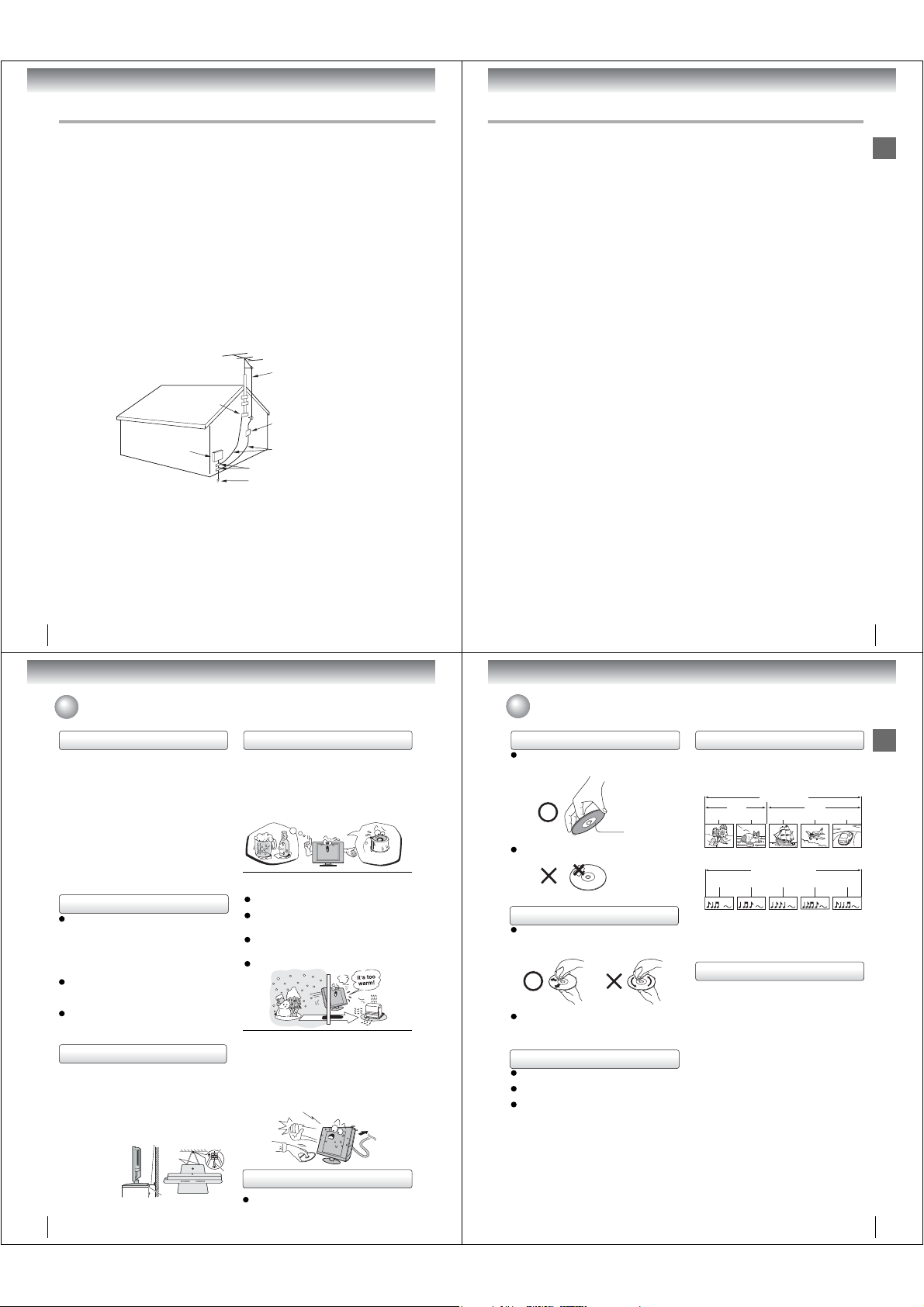
Notes on locating
Q WARNING: To prevent injury, this apparatus must be
securely attached to the oor/wall in accordance with
the installation instructions.
Q When you place this unit near a TV, radio, or VCR,
the playback picture may become poor and the sound
may be distorted. In this case, place the unit away
from the TV, radio, or VCR.
Q To avoid damage to this product, never place or store
the unit in direct sunlight; hot, humid areas; or areas
subject to excessive dust or vibration.
Q Always place the
TV on the oor or
a sturdy, level,
stable surface
that can support
the weight of the
unit. Use a sturdy
tie between the
TV’s rear hook
and the rear wall, pillar, etc., to secure the TV.
If you use a TV stand, x the TV by using the attached
band.
6
Sturdy tie (as short as possible)
Hooks
TV side
Band
Notes on moisture condensation
Moisture condensation damages the unit. Please
read the following carefully.
Moisture condensation occurs, for example, when you
pour a cold drink into a glass on a warm day. Drops
of water form on the outside of the glass. In the same
way, moisture may condense on the optical pick-up lens
inside this unit, one of the most crucial internal parts of
the unit.
Q Moisture condensation occurs during the
following cases.
When you bring the unit directly from a cold place to
a warm place.
When you use the unit in a room where you just
turned on the heater, or a place where the cold wind
from the air conditioner directly hits the unit.
In summer, when you use the unit in a hot and
humid place just after you move the unit from an air
conditioned room.
When you use the unit in a humid place.
Q Do not use the unit when moisture condensation
may occur.
If you use the unit in such a situation, it may damage
discs and internal parts. Remove the disc, connect the
power cord of the unit to the wall outlet, turn on the unit,
and leave it for two or three hours. After two or three
hours, the unit will have warmed up and evaporated any
moisture. Keep the unit connected to the wall outlet and
moisture condensation will seldom occur.
Clip
Screw
Notes on cleaning
TV top
Use a soft, dry cloth for cleaning.
Do not use any type of solvent, such as thinner and
benzine, as they may damage the surface of the unit.
Wait!
o
e
l
p
m
a
x
E
n
e
d
n
o
c
Notes on discs
On handling discs
Do not touch the playback side of the disc.
For example, handle the disc so that it is shown in
gure below.
f
m
o
i
s
t
u
r
e
s
a
t
i
o
n
!
Optical pick-up
lens
Do not attach paper or tape to discs.
Playback side
On cleaning discs
Fingerprints and dust on the disc cause picture and
sound deterioration. Wipe the disc from the center
outwards with a soft cloth. Always keep the disc
clean.
Do not use any type of solvent such as thinner,
benzine, commercially available cleaners or antistatic
spray for vinyl LPs. It may damage the disc.
On storing discs
Do not store discs in a place subject to direct sunlight
or near heat sources.
Do not store discs in places subject to moisture and
dust such as a bathroom or near a humidi er.
Store discs vertically in a case. Stacking or placing
objects on discs outside of their case may cause
Wall outlet
warping.
Structure of disc contents
Normally, DVD video discs are divided into titles, and
the titles are sub-divided into chapters. Video CDs and
Audio CDs are divided into tracks.
DVD video disc
Chapter 1 Chapter 2 Chapter 1 Chapter 2 Chapter 3
Video CD/Audio CD
Track 1 Track 2 Track 3 Track 4 Track 5
Each title, chapter or track is assigned a number, which
is called “title number”, “chapter number” or “track
number” respectively.
There may be discs that do not have these numbers.
DVD video disc
Title 1 Title 2
Video CD/Audio CD
Notes on copyright
The unauthorized recording, use, distribution, or
revision of copyrighted materials including, without
limitation, television programs, videotapes, and DVDs,
is prohibited under the Copyright Laws of the United
States and other countries, and may subject you to civil
and criminal liability.
This product incorporates copyright protection
technology that is protected by method claims of certain
U.S. patents and other intellectual property rights
owned by Macrovision Corporation and other rights
owners. Use of this copyright protection technology
must be authorized by Macrovision Corporation, and is
intended for home and other limited viewing uses only
unless otherwise authorized by Macrovision
Corporation. Reverse engineering or disassembly is
prohibited.
Introduction
7
Page 5
Introduction
Notes on discs (Continued)
About this owner’s manual
This owner’s manual explains the basic instructions
of this unit. Some DVD video discs are produced in a
manner that allows speci c or limited operation during
playback. As such, the unit may not respond to all
operating command. This is not a defect in the unit.
Refer to instruction notes of discs.
The following symbol may appear on the TV screen
during operation.
It means that the operation is not permitted by the TV/
DVD or the disc.
For example, sometimes it is unable to stop the
playback of copyright message of the disc when the
STOP (
) button is pressed. Alternatively, this symbol
may also indicate that the feature is not available for the
disc.
Notes on region numbers
The region number of this unit is 1. If region numbers,
which stand for their playable area, are printed on your
DVD video disc and you do not nd
playback will not be allowed by the player. (In this case,
the unit will display a message on-screen.)
Some DVDs that have no region code label may still be
subject to area restrictions and therefore not playable.
On Video CDs
This unit supports Video CDs equipped with the
PBC (Version 2.0) function. (PBC is the abbreviation
of Playback Control.) You can enjoy two playback
variations depending on types of discs.
• Video CD not equipped with PBC function
(Version 1.1)
Sound and movie can be played on this unit in the
same way as a DVD.
• Video CD equipped with PBC function
(Version 2.0)
In addition to operation of a Video CD not equipped
with the PBC function, you can enjoy playback of
interactive software with search function by using the
menu displayed on the TV screen (Menu Playback).
Some of the functions described in this owner’s
manual may not work with some discs.
8
ALL
1
or
, disc
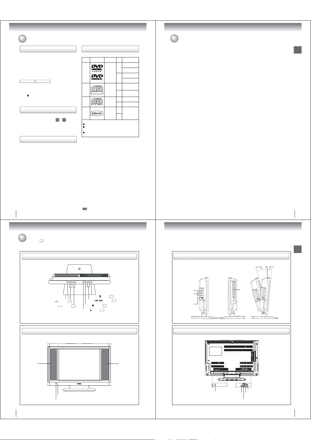
Playable discs
This unit can play the following discs.
Disc Mark Contents
DVD
video
discs
Video
CDs
DIGITAL VIDEO
Audio
CDs
®
DivX
The following discs are also available.
DVD-R/RW discs of DVD video format
CD-R/CD-RW discs of CD-DA, Video CD, MP3, WMA,
®
format
JPEG or DivX
Kodak Picture CD and FUJICOLOR CD format
Some of these discs may be incompatible.
• You cannot play discs other than those listed above.
• You cannot play discs of DVD-RAM, DVD-ROM, CDROM, Photo CD, etc., or non standardized discs even
if they may be labeled as above.
• Some CD-R/RWs cannot be played back depending
on the recording conditions.
• This unit uses the NTSC color system, and cannot play
DVD video discs recorded in any other color system
(PAL, SECAM, etc.).
• This unit can play an 8cm disc. Please do not use a
disc adapter. It may cause trouble.
• Please do not insert any disc of an irregular shape into
the unit, as it may interfere with the function of the unit.
You may not be able to remove it.
• Please do not use after market accessories, such as
a ring protector, as this may cause trouble with the
operation of the unit.
Because of problems and errors that can occur during
the creation of DVD and CD Software and/or the
manufacture of DVD and CD discs, Toshiba cannot
assure that the DVD player contained in this TV will
successfully play every disc bearing the DVD and CD
logos. If you happen to experience any dif culty playing
a DVD and/or CD disc on the DVD player contained in
this TV, please contact Toshiba Customer Service.
is a trademark of DVD Format/Logo Licensing
Corporation.
Audio
+
Video
(moving
pictures)
Audio
+
Video
(moving
pictures)
Audio
Audio
+
Video
(moving
pictures)
Disc
Size
12 cm
Approx. 80 minutes
8 cm
Approx. 160 minutes
Approx. 74 minutes
12 cm
Approx. 20 minutes
8 cm
Approx. 74 minutes
12 cm
Approx. 20 minutes
8 cm
12 cm
It depends on DivX®
8 cm
Maximum
playback time
Approx. 4 hours
(single sided disc)
Approx. 8 hours
(double sided disc)
(single sided disc)
(double sided disc)
(single sided disc)
(single sided disc)
(single sided disc)
(single sided disc)
quality
Contents
Introduction
IMPORTANT SAFEGUARDS ............................ 3
Precautions........................................................ 6
Notes on discs ................................................... 7
Contents ............................................................ 9
Identi cation of controls ................................... 10
Connections
Antenna connections ....................................... 14
Cable TV connections ..................................... 15
Connecting to optional equipment ................... 16
Power source................................................... 20
Basic setup
Setting the language........................................ 21
To memorize channels.....................................22
TV operation
TV operation .................................................... 23
Closed captions ............................................... 25
Picture control adjustment ............................... 26
Adjusting the picture mode .............................. 26
Selecting the color temperature....................... 27
Sound control adjustment ................................ 28
Stereo and Second Audio Program (SAP) ......28
Basic playback
Playing a disc ..................................................29
Advanced playback
Zooming.......................................................... 32
Locating desired scene................................... 32
Repeat playback ............................................. 33
A-B Repeat playback ...................................... 33
Program playback........................................... 34
Random playback ........................................... 34
Changing angles..............................................35
Title selection ...................................................35
DVD menu .......................................................35
Changing soundtrack language .......................36
Subtitles ...........................................................36
Disc status .......................................................37
To turn off the PBC ..........................................37
MP3/WMA/JPEG/DivX
and Audio CD operation ..................................38
Repeat and program playback
using le browser.............................................42
Function setup
Customizing the function settings ....................44
Temporary cancel the rating level
by DVD disc .....................................................50
Others
Language code list ..........................................51
Troubleshooting ...............................................52
Reception disturbances ...................................54
Speci cations ..................................................55
Limited Canada Warranty ................................56
®
Introduction
9
Introduction
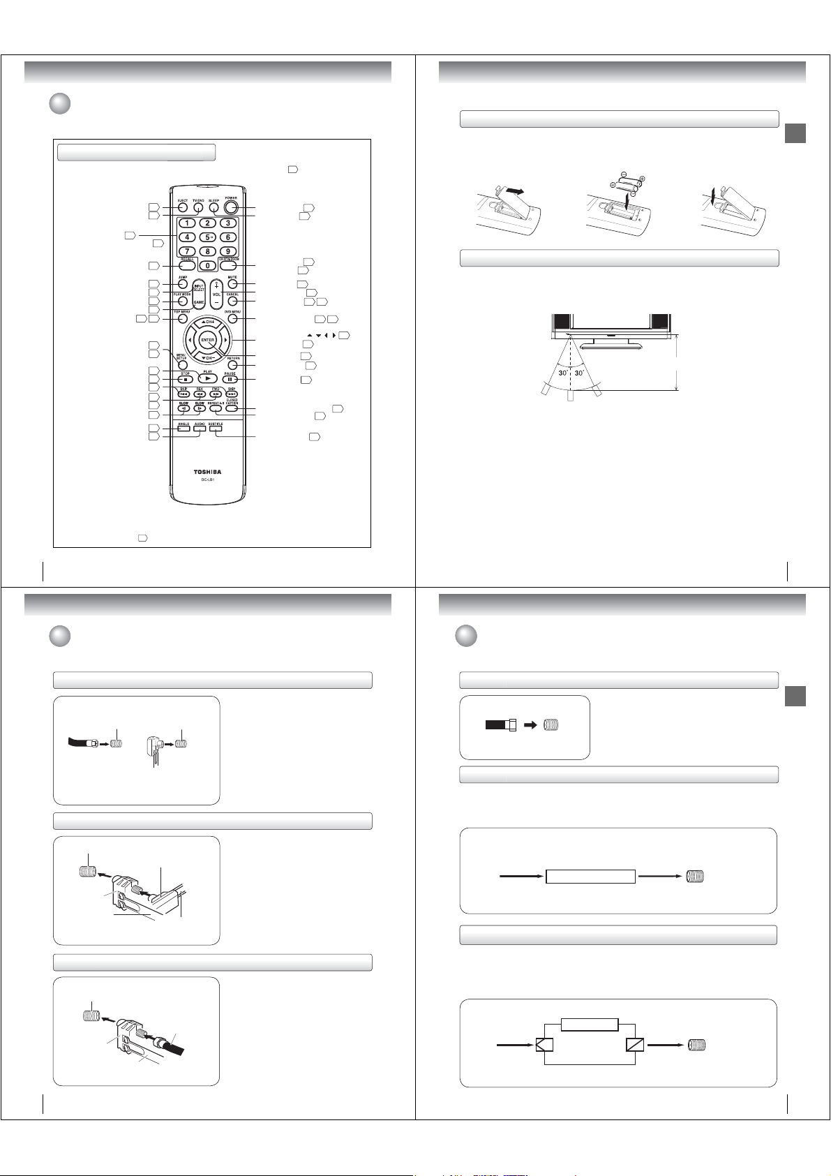
Identi cation of controls
See the page in for details.
Top
POWER button
VOLUME ( ) buttons
CHANNEL ( / ) buttons
29
23
22
EJECT ( ) button
SKIP ( / ) buttons
STOP( ) button
PLAY ( ) button
29
29
Front
Speaker Speaker
Side
Adjusting the angle of the base
Approx. 15° Approx. 5°
Introduction
Left Side Right Side
PHONES jack
AUDIO IN (L/R)
30
31
/VIDEO IN
(LINE 2 IN) jacks
S-VIDEO jack
Disc
slot
You can adjust
the angle of the
TV-screen for 5°
forward or for 15°
backward from
vertical angle.
Hold the base
of the TV while
adjusting the
angle.
Rear
COAXIAL DIGITAL AUDIO OUT jack
Remote sensor
POWER indicator
Antenna jack
DC input jack
10
VIDEO IN (LINE 1 IN) jack
COMPONENT VIDEO IN
B, PR) (LINE 1 IN) jacks
(Y, P
AUDIO IN (L/R) (LINE 1 IN) jacks
11
Page 6
Introduction
Identi cation of controls (Continued)
Remote control
The instructions in this manual describe the function on the remote control. See the page in for details.
Inserting batteries
Open the battery compartment
1
cover in the direction of the
arrow.
Install two “R03/AAA” batteries
23
(supplied), paying attention to
the polarity indicated in the
battery compartment.
Replace the compartment
cover.
Introduction
EJECT button
TV/DVD button
Direct channel selection
buttons (0
Numbered buttons (0
RECALL button
INPUT SELECT button
PLAY MODE button
TOP MENU button
SETUP button
SLOW buttons
ANGLE button
AUDIO button
*DVD MENU button
Use the DVD MENU button to
display the menu included on
many DVD video discs.
To operate a menu, follow the
instructions in “DVD menu.”
12
Connections
-
9)
23
JUMP button
GAME button
MENU button
PLAY button
STOP button
SKIP buttons
REV button
FWD button
-
35 40
35
30
29
22
9)
24
32
16
33
16
21
44
29
29
31
31
31
31
35
36
POWER button
SLEEP button
CH RTN button
ZOOM button
MUTE button
VOL +/- buttons
CANCEL button
*DVD MENU button
Direction buttons
CH +/
ENTER button
RETURN button
PAUSE button
CLOSED CAPTION button
REPEAT A-B button
SUBTITLE button
-
buttons
21
24
24
32
24
23
21 32
35 40
( / / / )
22
21
44
30
33
36
Operation
• Aim the remote control at the remote sensor and press control buttons to operate.
• Operate the remote control within 30° angle on either side of the remote sensor, up to a distance of approx. 5
meters.
21
Approx. 5 meters
25
Caution:
• Never throw batteries into a re.
Notes:
•
Be sure to use AAA size batteries.
• Dispose of batteries in a designated disposal area.
Batteries should always be disposed of with the environment in mind. Always dispose of batteries in accordance with
•
applicable laws and regulations.
• If the remote control does not operate correctly, or if the operating range becomes reduced, replace batteries with
new ones.
• When necessary to replace batteries in the remote control, always replace both batteries with new ones.
Never mix battery types or use new and used batteries in combination.
• Always remove batteries from remote control if they are dead or if the remote control is not to be used for an
extended period of time. This will prevent battery acid from leaking into the battery compartment.
13
Antenna connections
If you are using an indoor or outdoor antenna, follow the instructions below that correspond to your antenna system.
If you are using a cable TV service (CABLE), see page 15 for Cable TV connections.
Combination VHF/UHF antenna (Single 75 ohm cable or 300 ohm twin-lead wire)
Antenna
jack
75 ohm coaxial cable
(not supplied)
Antenna
jack
300-75 ohm matching
transformer (supplied)
Connect the 75 ohm cable from the combination
VHF/UHF antenna to the antenna jack on the
back of the TV/DVD.
If your combination VHF/UHF antenna has a
300 ohm twin-lead wire, use the 300-75 ohm
matching transformer.
Combination VHF/UHF antenna (Separate VHF and UHF 300 ohm twin-lead wires)
Antenna
jack
Combiner
(not supplied)
UHF 300 ohm
twin-lead wire
(not supplied)
300-75 ohm matching
transformer (supplied)
VHF 300 ohm
twin-lead wire
(not supplied)
Connect the UHF 300 ohm twin-lead wire to
the combiner (not supplied). Connect the VHF
300 ohm twin-lead wire to the 300-75 ohm
matching transformer. Attach the transformer to
the combiner, then attach the combiner to the
antenna jack on the back of the TV/DVD.
Separate VHF/UHF antennas (75 ohm VHF cable and 300 ohm UHF twin-lead wires)
Antenna
jack
Combiner
(not supplied)
UHF 300 ohm
twin-lead wire
(not supplied)
VHF 75 ohm
(not supplied)
Connect the VHF 75 ohm cable and UHF 300 ohm
twin-lead wire to the combiner (not supplied).
Attach the combiner to the antenna jack on the
back of the TV/DVD.
14
Cable TV connections
This TV/DVD has an extended tuning range and can tune most cable channels without using a Cable TV converter box.
Some cable companies offer “premium pay channels” in which the signal is scrambled. Descrambling these signals for
normal viewing requires the use of a descrambler device which is generally provided by the cable company.
For subscribers to basic cable TV service
For basic cable service not requiring a converter/descrambler
box, connect the Cable TV 75 ohm coaxial cable directly to the
Antenna jack on the back of the TV/DVD.
75 ohm
coaxial cable
Antenna
jack
For subscribers to scrambled cable TV service
If you subscribe to a cable TV service which requires the use of a converter/descrambler box, connect the
incoming 75 ohm coaxial cable to the converter/descrambler box. Using another 75 ohm coaxial cable, connect
the output jack of the converter/descrambler box to the antenna jack on the TV/DVD. Follow the connections
shown below. Set the TV/DVD to the output channel of the converter/descrambler box (usually channel 3 or 4)
and use the converter/descrambler box to select channels.
Incoming
75 ohm
Cable TV
For subscribers to unscrambled basic cable TV service with scrambled
premium channels
If you subscribe to a cable TV service in which basic channels are unscrambled and premium channels require
the use of a converter/descrambler box, you may wish to use a signal splitter and an A/B Switch box (available
from the cable company or an electronics supply store). Follow the connections shown below. With the switch in
the “B” position, you can directly tune any nonscrambled channels on your TV/DVD. With the switch in the “A”
position, tune your TV/DVD to the output of the converter/descrambler box (usually channel 3 or 4) and use the
converter/descrambler box to tune scrambled channels.
Incoming
75 ohm
Cable TV
Splitter
Converter/
descrambler
Converter/
descrambler
A/B switch
A
B
75 ohm cable to
TV/DVD
75 ohm cable
to TV/DVD
Antenna
jack
Antenna
jack
Connections
15
Page 7
Connections
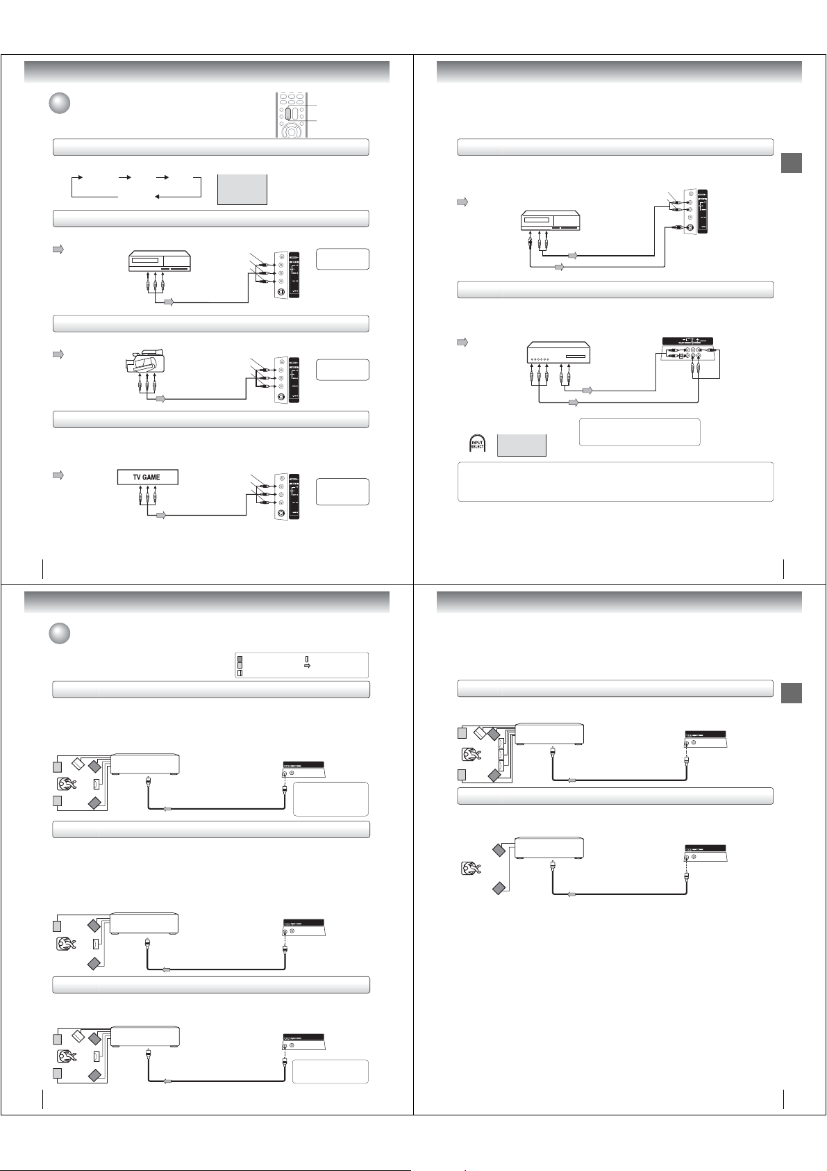
Connecting to optional equipment
You can enjoy VCR, camcorder or TV game with connection to external
input.
INPUT SELECT
GAME
Using the audio/video inputs
Press INPUT SELECT repeatedly to select the desired mode.
“VIDEO1”, “VIDEO2”, “ColorStream” or TV channel will display on the screen for 4 seconds.
TV Channel VIDEO1
(Rear lower left)
Note: This key will not operate in DVD mode.
ColorStream
VIDEO2
(Left side)
VIDEO1
Connecting to a VCR
To playback from the VCR, connect the VCR to the TV/DVD as shown.
Select the “VIDEO2” by pressing INPUT SELECT repeatedly.
: Signal ow
Note: Picture might be muted for some VCR playback. This is not a malfunction of this unit.
VCR
To Audio/Video OUT
Audio/Video cable (not supplied)
(white)
(yellow)
(red)
Left side (LINE 2 IN)
To AUDIO(L/R)/VIDEO IN
The LINE 1 IN
terminals can be used
in the same way.
Connecting to a camcorder
To playback from the camcorder, connect the camcorder to the TV/DVD as shown.
Select the “VIDEO2” by pressing INPUT SELECT repeatedly.
: Signal ow
Camcorder
To Audio/Video OUT
Audio/Video cable (not supplied)
(red)
(white)
(yellow)
Left side (LINE 2 IN)
To AUDIO(L/R)/VIDEO IN
The LINE 1 IN
terminals can be used
in the same way.
Connecting to a TV Game
You can enjoy playing a TV game on the screen by adjusting to suitable brightness for your eyes.
1. Connect a TV Game to the TV/DVD.
2. Select the “GAME” by pressing GAME.
The GAME mode screen appears.
• This TV/DVD has the GAME mode function (see page 24).
: Signal ow
To Audio/Video OUT
Notes:
• You can also change the TV screen to the desired mode by pressing the CH +/– buttons.
• The TV/DVD can also be used as a display device for many video games. However, due to the wide variety of different types of signal
generated by these devices and subsequent hook-up variations required, they have not all been included in the suggested connection
diagrams. You’ll need to consult each component’s Owner’s Manual for additional information.
• Interactive video games that involve shooting a “gun” type of joystick at on-screen target may not work on this TV/DVD.
Audio/Video cable (not supplied)
(white)
(yellow)
(red)
Left side (LINE 2 IN)
To AUDIO(L/R)/VIDEO IN
Only the LINE 2
IN terminals can
be used with the
GAME mode.
16
Connecting to an optional equipment with S-video output
If you connect a VCR with an S-VIDEO cable to the S-VIDEO IN jack on the left side of the TV/DVD, you must
also connect the audio cables to the AUDIO IN (LINE 2 IN) jacks on the left side of the TV/DVD. The S-VIDEO
cable only carries the video signal. The audio signal is separate.
Select the “VIDEO2” by pressing INPUT SELECT repeatedly.
: Signal ow
Ex. VCR with S-Video
To AUDIO (L/R) IN
Left side (LINE 2 IN)
(red)
(white)
(playback)
To S-VIDEO OUT
Note: When the S-VIDEO cable and the standard video cable are connected at the same time, the S-video cable takes precedence.
To Audio (L/R) OUT
Audio cable (not supplied)
S-Video cable (not supplied)
To S-VIDEO IN
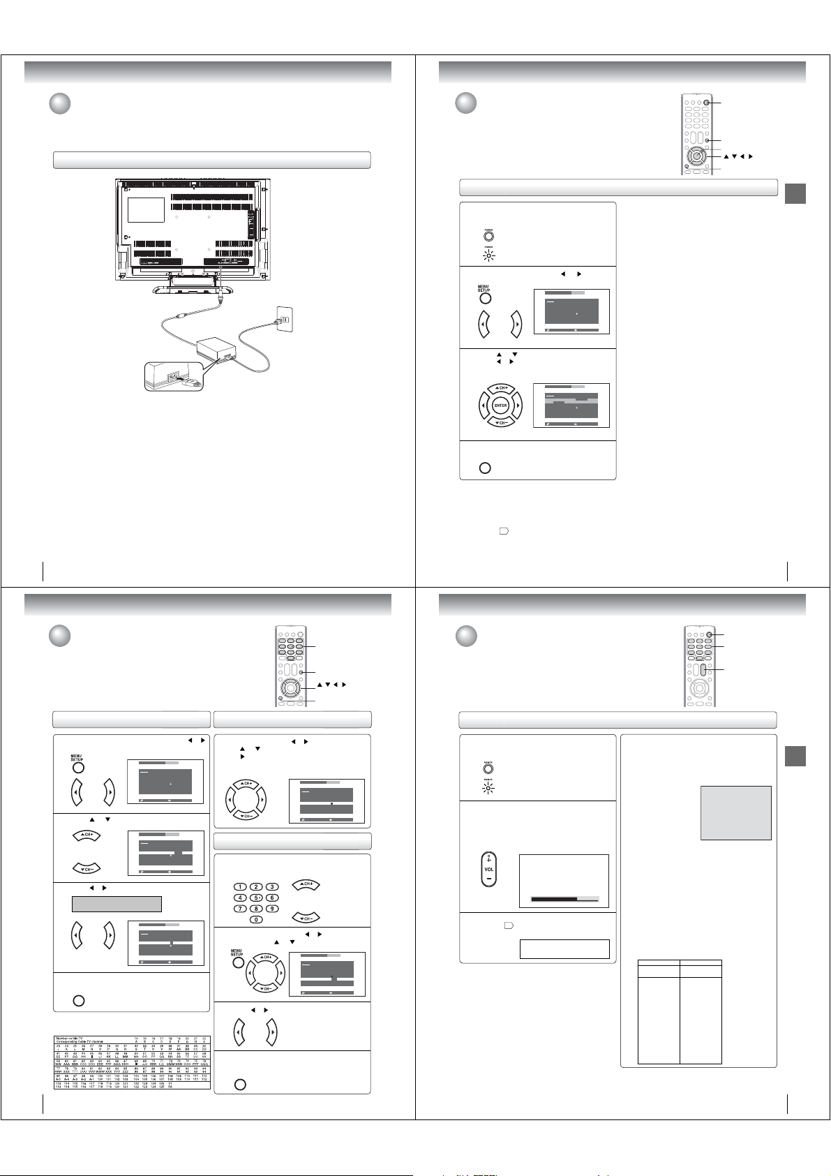
Connecting an optional equipment with ColorStream® (Component video) output
Your TV/DVD is capable of using ColorStream® (component video). Connecting your TV/DVD to a component
video compatible DVD player, such as a Toshiba DVD player with ColorStream
quality and performance.
Q Selecting Component input mode
Press INPUT SELECT repeatedly to
Notes:
• Refer to the owner’s manual of the connected equipment as well.
• When you connect the unit to other equipment, be sure to turn off the power and unplug all of the equipment from the wall outlet
• If you place the unit near a tuner or radio, the radio broadcast sound might be distorted. In this case, place the unit away from the
Ex. DVD player with Component video
: Signal ow
To Component
Video OUT
select “ColorStream” mode.
ColorStream
The ColorStream® inputs on this unit are for use with devices that output 480i interlaced signals and 480p progressive signals.
This unit will not accept or display 720p progressive scan signals or 1080i interlaced high-de nition signals. If you connect a highde nition set-top receiver, 720p progressive scan DVD player, or other similar device to the unit’s ColorStream
SWITCH THE DEVICE’S OUTPUT TO 480i INTERLACED OR 480p PROGRESSIVE MODE FIRST. Failure to do this will cause a
poor or no picture to display.
before making any connections.
tuner and radio.
To AUDIO (L/R) IN
To Audio OUT
Audio cable (not supplied)
Component video cable (not supplied)
When using the Component video cable,
an Audio cable must be connected to
AUDIO IN (L/R) (LINE 1 IN) jacks.
®
can greatly enhance picture
Rear lower right of the TV
To COMPONENT
(Y, P
B, PR) IN
®
inputs, YOU MUST
Connections
17
Connections
Connecting to optional equipment (Continued)
You can enjoy high quality dynamic sounds by connecting the
TV/DVD to optional audio equipment.
* This section uses the following reference mark.
: Front speaker
: Rear speaker
: Sub woofer
: Center speaker
: Signal ow
Connecting to an ampli er equipped with a Dolby® Digital decoder
Dolby Digital
Dolby Digital is the surround sound technology used in theaters showing the latest movies, and is now available to reproduce
this realistic effect in the home. You can enjoy motion picture and live concert DVD video discs encoded via the Dolby Digital
recording system with this dynamic realistic sound by connecting the TV/DVD to a 6 channel ampli er equipped with a Dolby
Digital decoder or Dolby Digital processor. If you have a Dolby Surround Pro Logic decoder, you will obtain the full bene t of
Pro Logic from the same DVD movies that provide full 5.1-channel Dolby Digital soundtracks, as well as from titles with the
Dolby Surround mark.
Ampli er equipped with a
Dolby Digital decoder
To COAXIAL
type digital
audio input
To COAXIAL DIGITAL
75 : coaxial cable (not supplied)
AUDIO OUT
Rear lower left of the TV
Manufactured under license
from Dolby Laboratories.
Dolby, and the double-D
symbol are trademarks of
Dolby Laboratories.
Connecting to an ampli er equipped with a Dolby Surround Pro Logic
Dolby Surround Pro Logic
You can enjoy the dynamic realistic sound of Dolby Surround Pro Logic by connecting an ampli er and speaker system (right and
left front speakers, a center speaker, and one or two rear speakers).
Q With an ampli er equipped with a Dolby Digital
Connect the equipment the same way as described in “Connecting to an ampli er equipped with a Dolby Digital decoder.”
Refer to that ampli er’s owner’s manual and set the ampli er so that you can enjoy Dolby Surround Pro Logic sound.
Q With an ampli er not equipped with a Dolby Digital
Connect the equipment as follows.
• This connection is only suitable for Video CDs and Audio CDs.
*
Ampli er equipped with a
Dolby Surround Pro Logic
To COAXIAL
type digital
audio input
75 : coaxial cable (not supplied)
To COAXIAL DIGITAL
AUDIO OUT
Rear lower left of the TV
* Connect one or two rear
speakers. The output sound
from the rear speakers will be
monaural even if you connect
two rear speakers.
Connecting to an ampli er equipped with a DTS® decoder
Digital Theater Systems (DTS)
DTS is a high quality surround technology used in theaters and now available for home use, on DVD video discs or audio CDs.
If you have a DTS decoder or processor, you can obtain the full bene t of 5.1 channel DTS encoded sound tracks on DVD
video discs or audio CDs.
Ampli er equipped with
a DTS decoder
To COAXIAL
type digital
audio input
75 : coaxial cable (not supplied)
Rear lower left of the TV
To COAXIAL DIGITAL
AUDIO OUT
“DTS” and “DTS Digital Out”
are registered trademarks of
DTS, Inc.
18
Connecting to an ampli er equipped with an MPEG audio decoder
MPEG2 sound
You can enjoy motion picture and live concert DVD video discs encoded via the MPEG2 recording system with dynamic
realistic sound by connecting an ampli er equipped with an MPEG2 audio decoder or MPEG2 audio processor.
Ampli er equipped with an
MPEG2 audio decoder
To COAXIAL
type digital
audio input
75 : coaxial cable (not supplied)
Rear lower left of the TV
To COAXIAL DIGITAL
AUDIO OUT
Connecting to an ampli er equipped with a digital audio input
2 channel digital stereo
You can enjoy the dynamic sound of 2 channel digital stereo by connecting an ampli er equipped with a digital audio input and
speaker system (right and left front speakers).
Note: PCM audio is limited to DVD or CD playback.
Ampli er equipped with a
Digital audio input
To COAXIAL
type digital
audio input
Notes:
• DO NOT connect the COAXIAL DIGITAL AUDIO OUT jack of the TV/DVD to the AC-3 RF input of a Dolby Digital Receiver.
This input on your A/V Receiver is reserved for Laserdisc use only and is incompatible with the COAXIAL DIGITAL AUDIO
OUT jack of the TV/DVD.
• Connect the COAXIAL DIGITAL AUDIO OUT jack of the TV/DVD to the “COAXIAL” input of a Receiver or Processor.
• Refer to the owner’s manual of the connected equipment as well.
• When you connect the TV/DVD to other equipment, be sure to turn off the power and unplug all of the equipment from the
wall outlet before making any connections.
• The output sound of the TV/DVD has a wide dynamic range. Be sure to adjust the receiver’s volume to a moderate listening
level. Otherwise, the speakers and your hearing may be damaged by a sudden high volume sound.
• Turn off the ampli er before you connect or disconnect the TV/DVD’s power cord. If you leave the ampli er’s power on, the
speakers may be damaged.
75 : coaxial cable (not supplied)
Rear lower left of the TV
To COAXIAL DIGITAL
AUDIO OUT
Connections
19
Page 8
Connections
Connections
Basic setup
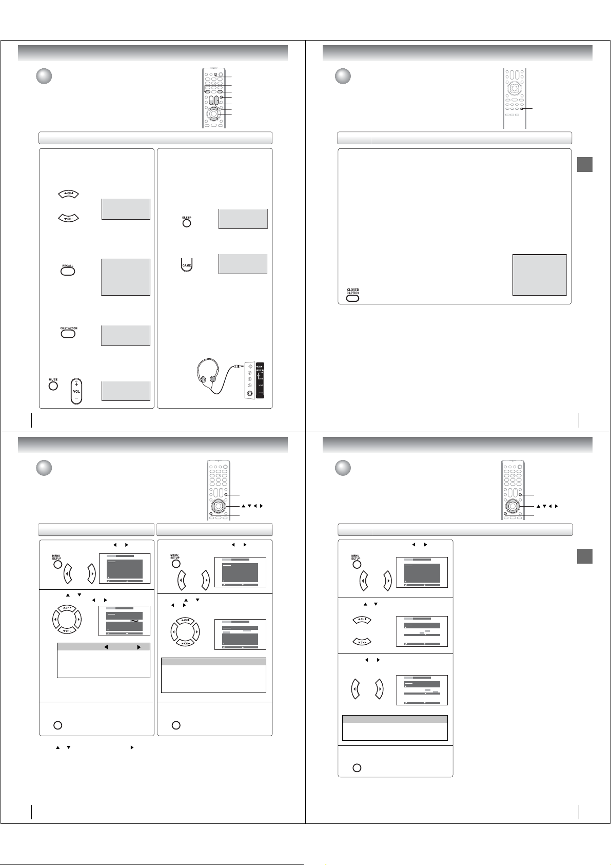
Power source
Power connection
AC 120V,
To DC input jack
TO USE AC POWER
1. Connect the AC cord to the AC adapter.
2. Connect the AC adapter plug into the TV/DVD’s DC input jack.
3. Connect the AC cord into a wall outlet.
Notes:
• Make sure to insert the plug of each cord securely.
• During use the AC adapter becomes warm. This is not a malfunction.
WARNING:
• DO NOT CONNECT THIS UNIT TO THE POWER USING ANY DEVICE OTHER THAN THE SUPPLIED AC ADAPTER OR
POWER CORD. THIS COULD CAUSE FIRE, ELECTRIC SHOCK, OR DAMAGE.
• DO NOT USE WITH A VOLTAGE OTHER THAN THE POWER VOLTAGE DISPLAYED. THIS COULD CAUSE FIRE,
ELECTRIC SHOCK, OR DAMAGE.
CAUTION:
• DO NOT USE THE AC ADAPTER IF IT IS COVERED BY A CLOTH ETC., OR PRESSED INTO A NARROW AREA.
THIS RESULTS IN POOR DISSIPATION OF HEAT AND MAY CAUSE FIRE, ELECTRIC SHOCK, OR DAMAGE.
• WHEN THIS UNIT IS NOT USED FOR AN EXTENDED PERIOD OF TIME, (E.G., AWAY ON A TRIP) IN THE INTEREST OF
SAFETY, BE SURE TO UNPLUG IT FROM THE WALL OUTLET.
• DO NOT PLUG/UNPLUG THE PLUG WHEN YOUR HANDS ARE WET. THIS MAY CAUSE ELECTRIC SHOCK.
• IF YOU NEED TO REPLACE THE SUPPLIED AC ADAPTER OR AC CORD, THE SPECIFIED AC ADAPTER AND AC
CORD MUST BE USED. CONTACT THE DEALER THAT YOU PURCHASED THE UNIT FROM.
2
AC adapter
(supplied)
60Hz
3
1
AC cord
(supplied)
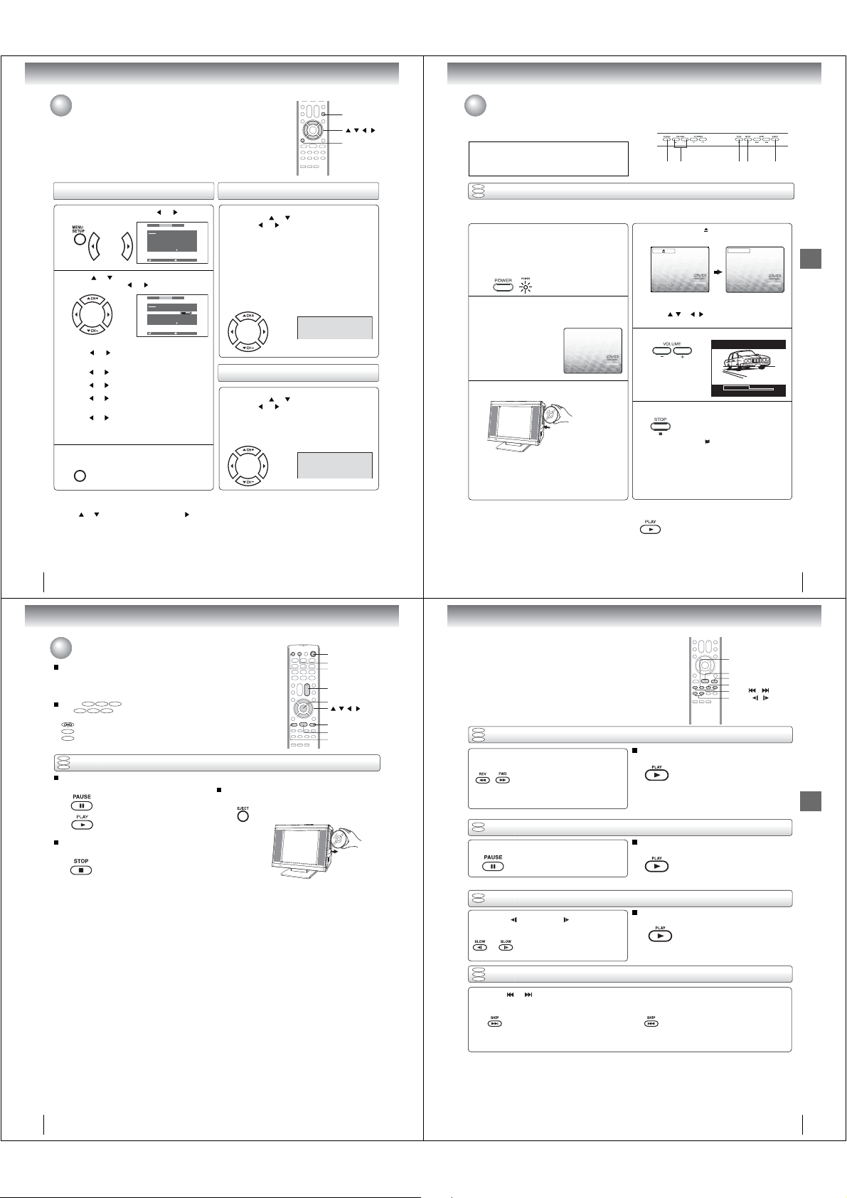
Setting the language
This TV/DVD can display the on screen language in English, Spanish or French in
the TV mode.
Select the language you prefer rst, then proceed with the other menu options.
Setting the language
To turn on the TV/DVD, press POWER.
The Power indicator on the front of the main unit
1
will light.
Press MENU and then press or to select
2
“SETUP”.
Press or to select “LANGUAGE”, then
press
or to select the desired language:
3
English (ENGLISH), Spanish (ESPAÑOL) or
French (FRANÇAIS), then press ENTER.
Press CANCEL to clear the menu screen.
4
CANCEL
Notes:
• If the unit does not operate properly, or No key operation
(by the unit and/or the remote control): Static electricity,
etc., may affect the TV/DVD’s operation. In such case,
disconnect the AC cord once, then connect it again.
• The TV section has its own menu and also DVD section has
its own menu
44
PICTURE AUDIO SETUP
SETUP
ENGLISH
LANGUAGE
CABLE
TV/CABLE
CH PROGRAM
ADD
ADD/ERASE
OFF
CLOSED CAPTION
:SELECT :ADJUST
PICTURE AUDIO SETUP
SETUP
ENGLISH
LANGUAGE
ENGLISH/FRANÇAIS/ESPAÑOL
CABLE
TV/CABLE
CH PROGRAM
ADD
ADD/ERASE
OFF
CLOSED CAPTION
:SELECT :ADJUST
.
POWER
CANCEL
ENTER
/ / /
MENU
Basic setup
20
Basic setup
To memorize channels
This TV/DVD is equipped with a channel memory feature which allows
channels to skip up or down to the next channel set into memory, skipping over
unwanted channels. Before selecting channels, they must be programmed
into the TV/DVD’s memory. In addition to normal VHF and UHF channels, this
TV/DVD can receive up to 113 Cable TV channels. To use this TV/DVD with an
antenna, set the TV/CABLE selection to the TV position. When shipped from
the factory, this selection is in the CABLE position.
TV/CABLE selection
Press MENU in the TV mode, then press or
to select SETUP.
1
Press or to select “TV/CABLE”.
2
Press or to select “TV” or “CABLE”.
3
TV - VHF/UHF channels
CABLE - Cable TV channels
Press CANCEL to clear the menu screen.
4
CANCEL
Cable TV chart
The chart below is typical of many cable system channel
allocations.
PICTURE AUDIO SETUP
SETUP
LANGUAGE
TV/CABLE
CH PROGRAM
ADD/ERASE
CLOSED CAPTION
:SELECT :ADJUST
PICTURE AUDIO SETUP
SETUP
LANGUAGE
TV/CABLE
CH PROGRAM
ADD/ERASE
CLOSED CAPTION
:SELECT :ADJUST
PICTURE AUDIO SETUP
SETUP
LANGUAGE
TV/CABLE
CH PROGRAM
ADD/ERASE
CLOSED CAPTION
:SELECT :ADJUST
ENGLISH
CABLE
ADD
OFF
ENGLISH
TV/CABLE
ADD
OFF
ENGLISH
TV/CABLE
ADD
OFF
22
0–9
CANCEL
/ / /
CH +/–
MENU
Automatic memory tuning
Press MENU, then press or to select SETUP.
or to select the “CH PROGRAM”, then
Press
press
.
The TV will begin memorizing all the channels
available in your area.
PICTURE AUDIO SETUP
SETUP
LANGUAGE
TV/CABLE
CH PROGRAM
ADD/ERASE
CLOSED CAPTION
:SELECT :ADJUST
ENGLISH
CABLE
ADD
OFF
To ADD/ERASE channels
Select the desired channel to be added or
deleted using Direct
1
CH +/–.
Press MENU, then press
SETUP. Press
2
Press or to select “ADD” or “ERASE”.
3
Press CANCEL to clear the menu screen.
Repeat steps 1 ~ 3 to add or erase other channel.
4
CANCEL
channel selection (0–9) or
or
or to select “ADD/ERASE”.
to select
PICTURE AUDIO SETUP
SETUP
LANGUAGE
TV/CABLE
CH PROGRAM
ADD/ERASE
CLOSED CAPTION
:SELECT :ADJUST
ENGLISH
CABLE
ADD/ERASE
OFF
21
TV operation
TV operation
POWER
0–9
VOL +/–
TV operation
To turn on the TV/DVD, press POWER.
The Power indicator on the front of the main unit
1
will light.
Adjust the volume level by pressing VOL + or
The volume level will be indicated on the
–.
2
screen by white bars. As the volume level
increases, so do the number of bars. If the
volume decreases, the number of white bars
also decreases.
VOLUME 32
Set the TV/CABLE selection to the appropriate
22
position.
3
Auto power off
If a station being viewed stops broadcasting, the TV will
automatically shut itself off after 15 minutes.
TV - VHF/UHF channels
CABLE
- Cable TV channels
Press direct channel selection (0–9) to select
the channel.
4
TV mode direct channel selection
When the TV/CABLE selection is in the TV
position, all channels can be instantly selected by
using two buttons. (for example, to select channel
2, press “0”, then “2”.
If you press only “2”,
channel selection
will be delayed for
a few seconds.) For
channels 10 and
above, press the 2
digits in order.
CABLE mode direct channel selection
When the TV/CABLE selection is in the CABLE
position, channels can be selected as follows:
TO SELECT CABLE TV CHANNELS:
1-9: Press “0” twice, then 1-9 as needed.
Example, to select channel 2, press
“002”.
10-12: Press “0”, then the remaining 2 digits.
Example, to select channel 12, press
“012”.
13-99: Press the 2 digits in order. Example, to
select channel 36, press “36”.
100-125: Press the 3 digits in order. Example, to
select channel 120, press “120”.
NOTE FOR CHANNELS 1-12:
If only 1 or 2 buttons are pressed, the corresponding
channel will be selected in 2 seconds.
Note:
If a channel with no broadcast is selected, the sound will
automatically be muted.
VHF
2-13
UHF
14-69
CATV
TV
VHF
2-13
STD/HRC/IRC
14-36
(A) (W)
37-59
(AA) (WW)
60-85
(AAA) (ZZZ)
86-94
(86) (94)
95-99
(A-5) (A-1)
100-125
(100) (125)
01
(5A)
02
TV operation
ANT
23
Page 9
TV operation
TV operation (Continued)
TV operation
Q CHANNEL UP/DOWN
Press and release CH + or –. The channel
automatically stops at the next channel set into
memory.
For proper operation, before selecting channels,
they should be set into the memory. See page 22 “To
memorize channels”.
ANT
12
Q RECALL
Press RECALL to display the current informations on the
screen. Press RECALL again to clear the display.
• Channel number or external input mode
• Stereo or SAP (Second Audio Program) audio status
Q CH RETURN
This button allows you to go back to the last channel
selected by pressing CH RTN. Press CH RTN again to
return to the last channel you were watching.
Q MUTE
Press MUTE to switch off the sound. The TV/DVD’s
sound will be silenced and “MUTE” will appear brie y
on the screen. The sound can be switched back on by
pressing this button again or one of VOL +/–.
STEREO
SAP
ANT
TV
12
ANT
7
SLEEP
RECALL
CH RTN
MUTE
VOL +/–
GAME
CH +/–
Q SLEEP
To set the TV/DVD to turn off after a preset amount of
time, press SLEEP on the remote control. The clock
will count up 10 minutes for each press of SLEEP
(0h00m, 0h10m,... 1h50m, 2h00m). After the sleep
time is programmed, the display will appear brie y
every ten minutes to remind you that the sleep timer
is operating. To con rm the sleep timer setting, press
SLEEP and the remaining time will be displayed for a
few seconds. To cancel the sleep timer, press SLEEP
repeatedly until the display turns to 0h00m.
SLEEP
0h00m
Q GAME MODE
After connecting a TV Game to the unit (see page 16),
press GAME. The TV screen changes to the Game
mode.
GAME
• The Game mode screen is adjusted to the suitable
brightness for your eyes.
• If GAME is pressed during standby mode, the unit
turns on automatically and the Game mode screen
appears on the screen.
• Interactive video games that involve shooting a “gun”
type of joy-stick at an on-screen target may not work
on this TV/DVD.
Q HEADPHONES
Insert a stereo headphones (not supplied) with a 1/8”
mini plug into the HEAD PHONES jack on the front
panel. If you connect headphones, the sound from TV
speakers is muted.
Closed captions
WHAT IS CLOSED CAPTIONING?
This television has the capability to decode and display closed captioned
television programs. Closed captioning will display text on the screen for
hearing impaired viewers or it will translate and display text in another
language.
CLOSED
CAPTION
Closed captions
Captions: This closed caption mode will display text on the screen in English or another language
(depending on the setting of the closed captions CH 1/2).
Generally, closed captions in English are transmitted on captions channel 1 and closed captions in other
languages are transmitted on captions channel 2.
Text: The text closed caption mode will usually ll the screen with a programming schedule or other
information.
After selecting a closed caption mode, it will stay in effect until it is changed, even if the channel is changed.
If the captions signal is lost due to a commercial or a break in the signal, the captions will reappear when the
signal is received again. If the channels are changed, the captions will be delayed approximately 10 seconds.
The captions will appear in places on the screen where they will least interfere with the picture, usually on
the bottom of the screen. News programs will usually show three-line closed captions which scroll onto the
screen.
Most other shows provide two or three lined captions placed near the character who is speaking so the viewer
can follow the dialogue. Words in italics or underlined describe titles, words in foreign languages or words
requiring emphasis. Words that are sung usually appear enclosed by musical notes.
For television programs broadcasting with closed captions, look in your TV guide for the closed captions
symbol (CC).
TO VIEW CLOSED CAPTIONS
Press CLOSED CAPTION to switch between normal TV and the two closed
caption modes (captions and full screen text). Closed captioning will display text
on the screen for hearing impaired viewers.
• You can also select the closed captions in SETUP menu in the TV mode.
Notes:
• When selecting closed captions, the captioning will be delayed approximately 10 seconds.
• If no caption signal is received, no captions will appear, but the television will remain in the caption mode.
• Misspellings or unusual characters may occasionally appear during closed captioning. This is normal with closed captioning,
especially with live programs. This is because during live programs, captions are also entered live. These transmissions do
not allow time for editing.
• When captions are being displayed, on-screen displays, such as volume and mute may not be seen or may interfere with
closed captions.
• Some cable systems and copy protection systems may interfere with the closed captioned signal.
• If using an indoor antenna or if TV reception is very poor, the closed caption decoder may not appear or may appear with
strange characters or misspelled words. In this case, adjust the antenna for better reception or use an outdoor antenna.
CLOSED CAPTION OFF
TV operation
MUTE
24
TV operation
Picture control adjustment/
Adjusting the picture mode
Picture controls are factory preset but you can adjust them individually as follows:
And also you can select four picture modes—Standard, Sports, Movie, and
Memory—as described in the following table:
Picture control adjustment Adjusting the picture mode
Press MENU and then press or to select
“PICTURE”.
1
Press or to select the item you want to
adjust, then press
2
Selection Pressing
BRIGHTNESS darker lighter
CONTRAST lower higher
COLOR paler deeper
TINT reddish greenish
SHARPNESS softer sharper
Note:
The CONTRAST default setting is set to
maximum (+50) at the factory.
Press CANCEL to clear the menu screen.
3
CANCEL
Q To return all adjustments to the factory preset levels
Press
or to select “RESET”, then press .
PICTURE AUDIO SETUP
PICTURE
SPORTS
MODE
25
BRIGHTNESS
50
CONTRAST
25
COLOR
00
TINT
25
SHARPNESS
:SELECT :ADJUST
or to adjust the setting.
PICTURE AUDIO SETUP
PICTURE
SPORTS
MODE
25
BRIGHTNESS
50
CONTRAST
25
COLOR
00
TINT
25
SHARPNESS
:SELECT :ADJUST
Press MENU and then press or to select
“PICTURE”.
1
Press or to select “MODE”, then press
or to select the desired picture mode.
2
Mode Picture quality
SPORTS Bright and dynamic picture (factory-set)
STANDARD Standard picture quality (factory-set)
MOVIE Movie-like picture setting (factory-set)
MEMORY Your personal preferences (set by you;
see “Picture control adjustment” as left)
Press CANCEL to clear the menu screen.
3
CANCEL
Note:
You cannot select “MODE” in the Game mode.
CANCEL
/ / /
MENU
PICTURE AUDIO SETUP
PICTURE
SPORTS
MODE
25
BRIGHTNESS
50
CONTRAST
25
COLOR
00
TINT
25
SHARPNESS
:SELECT :ADJUST
PICTURE AUDIO SETUP
PICTURE
SPORTS
MODE
SPORTS/STANDARD/MOVIE/MEMORY
25
BRIGHTNESS
50
CONTRAST
25
COLOR
00
TINT
25
SHARPNESS
:SELECT :ADJUST
Selecting the color temperature
Selecting the color temperature
Press MENU and then press or to select
“PICTURE”
1
Press or to select “COLOR TEMPERATURE”.
2
Press or to select the desired color
mode.
3
Mode Picture quality
COOL Bluish
MEDIUM Neutral
WARM Reddish
Press CANCEL to clear the menu screen.
4
CANCEL
PICTURE AUDIO SETUP
PICTURE
SPORTS
MODE
25
BRIGHTNESS
50
CONTRAST
25
COLOR
0
TINT
25
SHARPNESS
:SELECT :ADJUST
PICTURE AUDIO SETUP
PICTURE
COLOR
COOL
TEMPERATURE
COOL/MEDIUM/WARM
RESET
:SELECT :ADJUST
PICTURE AUDIO SETUP
PICTURE
COLOR
WARM
TEMPERATURE
COOL/MEDIUM/WARM
RESET
:SELECT :ADJUST
25
CANCEL
/ / /
MENU
TV operation
Note:
You cannot select “COLOR TEMPERATURE” in the
Game mode.
26
27
Page 10
TV operation
Basic playback
Sound control adjustment/
Stereo and Second Audio Program (SAP)
Sound controls are factory preset but you can adjust them individually as follows:
The TV/DVD is equipped with a feature known as multi-channel TV sound or
MTS. MTS broadcasts greatly enhance TV viewing by bringing you programs
with high delity stereo sound.
MTS also provides an extra channel called the Second Audio Program or SAP
which broadcasters can use to transmit a second language for bilingual
transmission or for other purposes.
Sound control adjustment
Press MENU and then press or to select
“AUDIO”.
1
Press or to select the item you want to
adjust, then press
2
MTS
or to select “STR” (STEREO), “SAP” or
Press
“MONO”.
BASS:
or to adjust the bass sound.
Press
TREBLE:
Press
or to adjust the treble sound.
BALANCE:
or to obtain an equal sound level from
Press
both speakers.
SURROUND:
or to select “ON” or “OFF”.
Press
ON:
The dynamic presence and sound created offers
a thoroughly enjoyable listening experience.
OFF: Normal sound.
Press CANCEL to clear the menu screen.
3
CANCEL
Q To return BASS/TREBLE/BALANCE control
adjustments to the factory preset levels
Press
or to select “RESET”, then press .
PICTURE AUDIO SETUP
AUDIO
MTS
BASS
TREBLE
BALANCE
SURROUND
RESET
:SELECT :ADJUST
or to adjust the setting.
PICTURE AUDIO SETUP
AUDIO
MTS
BASS
TREBLE
BALANCE
SURROUND
RESET
:SELECT :ADJUST
STEREO
25
25
00
OFF
STEREO
25
25
00
OFF
Listening to stereo sound
Repeat step 1 in “Sound control adjustment” on
left, then press
Then press
When the TV is turned on or a channel selection
is made, the “STEREO” will appear on the screen.
This means that Stereo broadcasting is available.
You can enjoy stereo sound from the left and right
speakers.
• When mono broadcasting is received, no indication is
displayed.
• If the broadcast signal is not strong enough or clear
stereo sound is not available, select “MONO”.
The noise may be eliminated.
Listening to SAP (Second Audio Program)
Repeat step 1 in “Sound control adjustment” on
left, then press
Then press
When the TV is turned on or a channel selection is
made, the “SAP” will appear on the screen.
This means that the Second Audio Program
broadcasting is available.
or to select “MTS”.
or to select “STR”.
STEREO
or to select “MTS”.
or to select “SAP”.
STEREO
SAP
CANCEL
/ / /
MENU
Playing a disc
This section shows you the basics on how to play a disc.
CAUTION
Keep your ngers well clear of the disc slot when disc is
loading or unloading. Neglecting to do so may cause
serious personal injury.
DVD
VCD
Basic playback
CD
Preparations:
• When connecting to other equipment, turn the power off.
Press POWER on the unit or on the remote
control to turn on the unit.
1
The Power indicator on the front of the main unit will
light.
• Every time you press POWER, the TV/DVD starts
from TV mode.
• When using an ampli er, switch on the ampli er.
Press TV/DVD on the remote control to select DVD
mode.
2
The DVD startup screen will appear on the screen.
Load a disc in the disc slot.
3
Load the disc in the disc slot with the label side facing
forward. (If the disc has a label.) Hold the disc without
touching either of its surfaces, align it with the guides,
and place it in position.
POWER
VOLUME
+
On the TV-screen, “
then playback commences.
4
A menu screen will appear on the TV screen if the
disc has a menu feature.
Press
/ or / to select title, then press
ENTER. Title is selected and play commences.
Press VOLUME + or – to adjust the volume.
5
Press STOP to end playback.
6
Q To start playback in the stop mode
Press PLAY.
PLAY STOP EJECT
/–
” changes to “Reading” and
Reading
VOLUME 32
Q Resuming facility
• The unit records the stopped
point, depending on the disc.
” appears on the screen.
“
Press PLAY to resume
playback (from the scene point).
• If you press STOP again
(“Q” appears on the screen.),
the unit will clear the stopped
point.
Basic playback
28
Basic playback
Playing a disc (Continued)
To obtain a higher quality picture
Occasionally, some picture noise may appear on the TV screen while playing a
DVD video disc because the high resolution pictures on these discs include a lot
of information. In such case, you may reduce the SHARPNESS with the Picture
control adjustment menu (see page 26).
DVD VCD CD
About
DVD VCD CD
The
function described under that heading.
: You can use this function with DVD video discs.
VCD
: You can use this function with Video CDs.
CD
: You can use this function with Audio CDs and CD-R/RW CDs.
DVD
VCD
Basic playback
CD
To pause playback (still mode)
Press PAUSE during playback.
To stop playback
Press STOP.
Notes:
• If a non-compatible disc is loaded, “Incorrect Disc”, “Region Code Error” or “Parental Error” will appear on the TV screen
according to the type of loaded disc. In this case, check your disc again (see pages 8 and 48).
• Some discs may take a minute or so to start playback.
• When you set a single-faced disc label downwards (ie. the wrong way up), “Reading” will appear on the display for a few
minutes and then “Incorrect Disc” will continue to be displayed.
• Some discs may not work the resuming facility.
• Resuming cannot function when you play a PBC-featured Video CD while the PBC is on. To turn off the PBC, see page 37.
• Some playback operations of DVDs may be intentionally xed by software producers. Since this unit plays DVDs according
to the disc contents the software producers designed, some playback features may not be available. Also refer to the
instructions supplied with the DVDs.
• Do not move the unit during playback. Doing so may damage the disc.
• Use the EJECT button to unload and eject the disc.
• Do not put any objects other than discs on the disc slot. Doing so may cause the unit to malfunctions.
• There may be a slight delay between the button is pressed and the function activates.
icons on the heading bar show the playable discs for the
To resume normal playback, press
PLAY.
• The sound is muted during still
mode.
To remove the disc
Press EJECT.
Remove the disc after the disc comes
out.
POWER
TV/DVD
EJECT
VOL +/–
ENTER
/ / /
PAUSE
PLAY
STOP
Note:
If the unit does not operate properly:
Static electricity, etc., may affect the TV/DVD’s operation. In such
case, disconnect the AC cord, then connect it again.
REV
PLAY
PAUSE
FWD
SKIP
/
SLOW /
DVD
VCD
Playing in fast reverse or fast forward directions
CD
Press REV or FWD during playback.
REV: Fast reverse playback
FWD: Fast forward playback
Each time you press REV or FWD
button, the playback speed changes.
DVD
Playing frame by frame
VCD
Press PAUSE during still playback.
DVD
VCD
Press SLOW (REVERSE) or (FORWARD)
during playback.
DVD
VCD
CD
Press SKIP or repeatedly to display the chapter or track number you want.
Playback starts from the selected chapter or track.
Note:
A “Prohibition” symbol “” may appear at the upper right of the screen. This symbol means either the feature you tried is not
available on the disc, or the TV/DVD cannot access the feature at this time. This does not indicate a problem with the TV/DVD.
Each time you press PAUSE, the
picture advances one frame.
Playing in slow-motion
Each time you press the button, the
slow-motion speed changes.
Locating a chapter or track
To locate succeeding chapters or
tracks.
To resume normal playback
Press PLAY.
Notes:
• The TV/DVD mutes sound during reverse and forward scan
of DVD and Video CD discs. However, the TV/DVD plays
sound during fast forward or fast reverse play of audio CDs.
• The playback speed may differ depending on the disc.
To resume normal playback
Press PLAY.
Note:
The sound is muted during frame by frame playback.
To resume normal playback
Press PLAY.
Notes:
• The sound is muted during slow-motion playback.
• The Video CD cannot play Reverse Slow.
Playback starts from the beginning of
the current chapter or track.
When you press twice in quick successions,
playback starts from the beginning of
the preceding chapter or track.
29
Basic playback
30
31
Page 11
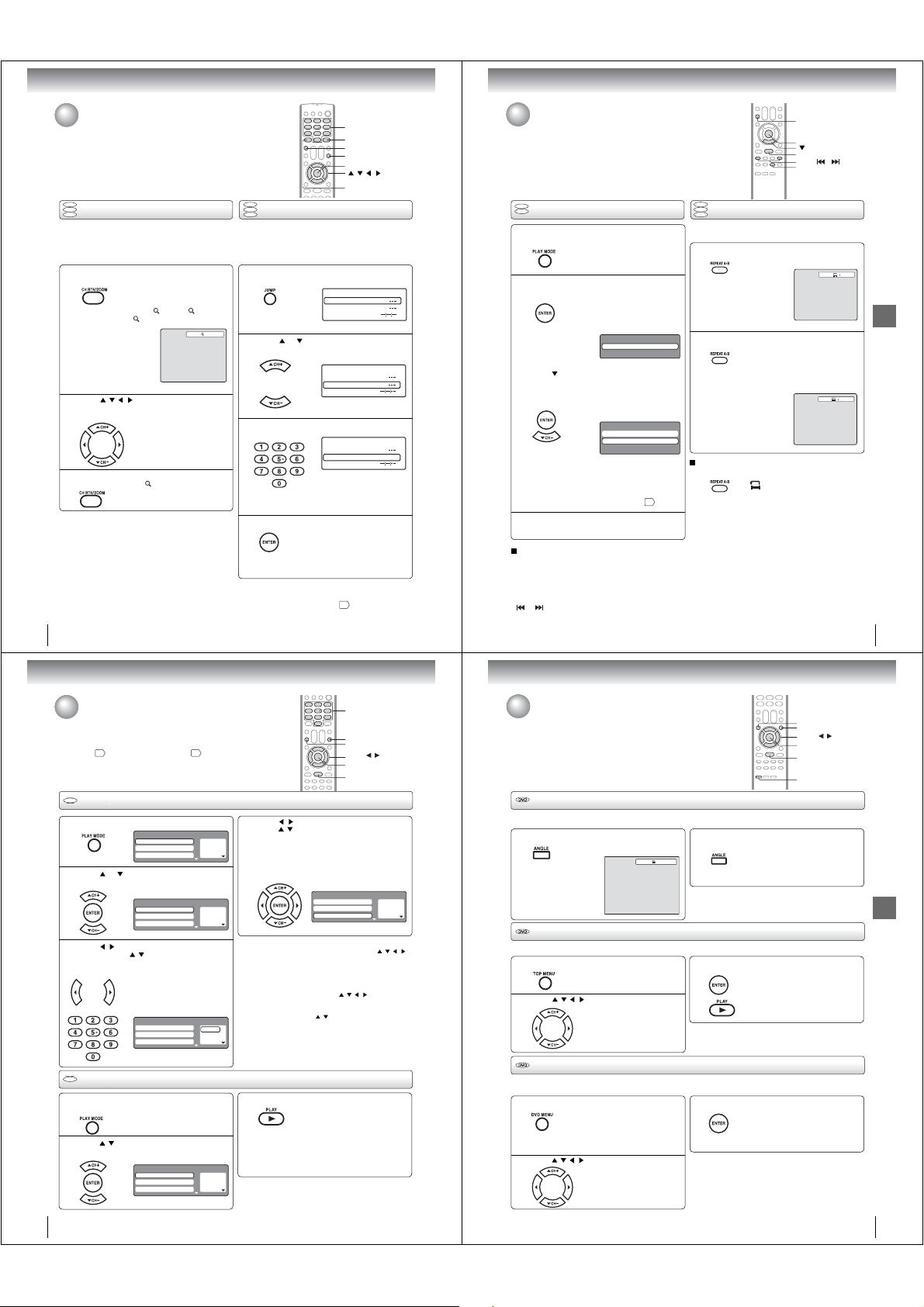
Advanced playback
Zooming/Locating desired scene
DVD
VCD
Zooming
CD
This unit will allow you to zoom in on the frame image.
You can then make selections by switching the position
of the frame.
Press ZOOM during playback.
1
2
3
Notes:
• You can select the Pause, Slow or Search playback in the
zoom mode.
• Some discs may not respond to zoom feature.
32
The center part of the image will be
zoomed in.
Each press of ZOOM will change
the ZOOM
1 (x 1.3), 2 (x 1.5)
3 (x 2.0).
and
Press / / / to view a different part of the
frame.
You may move the frame from
the center position to UP, DOWN,
LEFT or RIGHT direction.
In the zoom mode, press ZOOM repeatedly to
return to a 1:1 view (
Off).
1
0–9
ZOOM
JUMP
CANCEL
ENTER
/ / /
RECALL
DVD
VCD
Locating desired scene
CD
Use the title, chapter and time recorded on the DVD disc
to locate the desired point to playback. In the case of
VCD/Audio CD discs, time and track are used to locate
the desired point to playback.
To check the title, chapter/track and time, press RECALL.
Press JUMP during playback or resume stop
mode.
1
Press or to select the “Time”, “Title/
Track” or “Chapter”.
2
Press Number buttons (0–9) to input the
number.
3
• If you input a wrong number, press
CANCEL.
• Refer to the package supplied with
the disc to check the numbers.
Press ENTER. Playback starts.
4
Note:
In case of the Video-CD playback with PBC, the JUMP does
not work. To turn off PBC, see page
• When you change the title,
playback starts from Chapter 1 of
the selected title.
• Some discs may not work in the
above operation.
Jump
Title
Chapter
Time
Jump
Title
Chapter
Time
Jump
Title
Chapter 12
Time
.
37
Repeat playback/A-B Repeat playback
DVD
Repeat playback
VCD
Press PLAY MODE during playback or stop
mode.
1
[DVD]
Press ENTER repeatedly to select “Chapter”
2
or “Title”.
[Video CD]
Press
Press ENTER repeatedly to select “Track” or
“All”.
• If you set the repeat mode during stop mode,
press PLAY to start Repeat playback.
[Audio CD and MP3/WMA CD]
Please see “Repeat playback (CD)”
Press PLAY MODE again to clear the screen.
3
To resume normal playback
Select Repeat : “Off” in step 2.
Notes:
• Some discs may not work with the repeat operation.
• In case of Video CD with PBC, Repeat function is
prohibited during playback.
• Chapter/Track repeat function is canceled whenever SKIP
or is pressed.
to select “Repeat”.
The unit automatically
starts repeat playback after
nishing the current title or
chapter.
Play Mode
Repeat : Off
The unit automatically
starts repeat playback after
nishing the current track.
Play Mode
Mode : Off
Repeat : Off
42
DVD
VCD
A-B Repeat playback
CD
A-B repeat playback allows you to repeat a section
between two selected points.
Press REPEAT A-B during playback.
1
Press REPEAT A-B again.
2
To resume normal playback
Press REPEAT A-B again.
“
.
Notes:
• In A-B Repeat mode, subtitles near the A or B locations may
not be displayed.
• You cannot set the A-B Repeat for the scenes that include
multiple angles.
• A-B Repeat playback does not work when Repeat playback
is activated.
• You may not be able to set A-B Repeat during certain
scenes of the DVD.
• A-B Repeat does not work with an interactive DVD, MP3/
WMA/JPEG CD.
• In case of Video CD with PBC, A-B Repeat is prohibited.
PLAY MODE
ENTER
PLAY
SKIP /
REPEAT A-B
The start point is selected.
The end point is selected. Playback
starts at the point that you selected.
Playback stops at the end point and
returns to Point A automatically, then
starts again.
” appears on the screen.
Off
A
AB
Advanced playback
33
Advanced playback
Program playback/Random playback
You can arrange the playback order of tracks or les on the disc. And
the unit can also select tracks or les at random and playback them.
These feature works for Video CD.
For Audio CD and MP3/WMA CD, please see “Random playback
and “Program playback (CD)” 43.
(CD)”
42
VCD
Program playback
Press PLAY MODE in the stop mode.
1
Press or to select “Mode”, then press
ENTER repeatedly to select “Program”.
2
Press / to select the programming
position. Press
3
buttons (0–9) to input the track.
VCD
Random playback
Press PLAY MODE during playback or stop
mode.
1
Press / to select “Mode”, then press
ENTER to select “Random”.
2
Play Mode
Mode : Off
Repeat : Off
Program Playback
Play Mode
Mode : Program
Repeat : Off
Program Playback
/ and then use Number
• To program others, repeat step 3.
• If you input a wrong number, press
CANCEL.
Play Mode
Mode : Program
Repeat : Off
Program Playback
Play Mode
Mode : Random
Repeat : Off
Program Playback
4
1
---
2
---
3
---
1
---
2
---
3
---
Q To change the program
1. Select Mode to “Program” (as step 2), press
2. Press Number buttons (0–9) to overwrite the new
Q To clear the program one by one
Select Mode to “Program”, press
Q To clear all the programs
At the left column, press
1 9
Notes:
2
---
3
---
• In playing back the Video CD with PBC, you cannot set
• The program is canceled when you eject the disc or turn the
Press PLAY
3
The Random Playback will start.
1
---
2
---
3
---
Note:
In case of Video CD with PBC, you cannot set Random
function during playback.
34
0–9
CANCEL
PLAY MODE
/
V/W/
ENTER
PLAY
Press / to return to the left column, then
/ to select the “Program Playback”
press
and press ENTER.
The programs you selected will start to playback
in order.
• To resume normal playback,
select Mode: “Off” in step 2.
Play Mode
Mode : Program
Repeat : Off
Program Playback
to select the track/ le number you want to change, then
press CANCEL.
track/ le number.
track number. Then press CANCEL.
Then press ENTER.
Program playback.
power off.
• If you set “Random” during playback mode,
Random playback will begin after the track/ le
that is currently being played has ended.
• To resume normal playback,
select Mode: “Off” in step 2.
/ to select “Clear Program”.
.
1 9
2 3
3 11
/ / /
/ / / to select the
Changing angles/Title selection/DVD menu
TOP MENU
DVD MENU
V/W/
/
ENTER
PLAY
ANGLE
Changing angles
When playing back a disc recorded with multi-angle facility, you can change the angle that you are viewing the scene from.
Press ANGLE during playback.
1
The current angle will appear.
1/2
Title selection
Two or more titles are recorded on some discs. If the title menu is recorded on the disc, you can select the desired title.
Press TOP MENU during playback.
1
2
Title menu appears on the screen.
Press / / / to select the desired title.
DVD menu
Some DVDs allow you to select the disc contents using the menu.
When you playback these DVDs, you can select the subtitle language and soundtrack language, etc. using the menu.
Press DVD MENU during playback.
1
2
The DVD menu appears on the
screen.
• Press DVD MENU again to resume
playback at the scene when you
pressed DVD MENU.
/ / / to select the desired item.
Press
Press ANGLE repeatedly until the desired
angle is selected.
2
Note:
Depending on the DVD, you may not be able to change the
angles even if multi-angles are recorded on the DVD.
Press ENTER or PLAY.
3
Note:
Depending on the DVD, you may not be able to select the title.
Depending on the DVD, a “title menu” may simply be called a
“menu” or “title” in the instructions supplied with the disc.
3
Note:
Depending on the DVD, you may not be able to resume playback
from the scene point when you press the DVD MENU button.
The playback of the selected title will
start.
Press ENTER.
The menu continues to another
screen. Repeat steps 2 and 3 to set
the item completely.
Advanced playback
35
Page 12
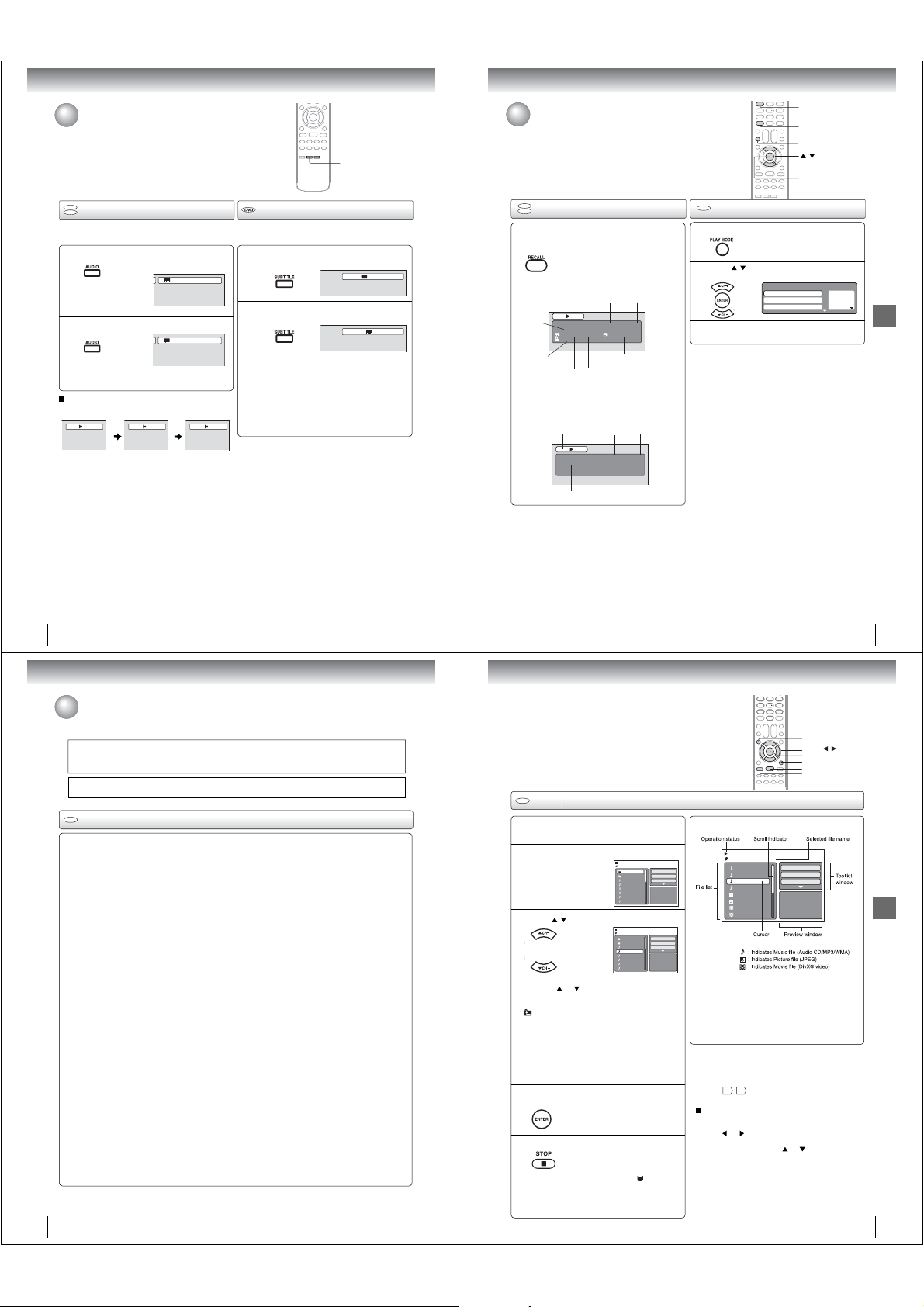
Advanced playback
Changing soundtrack language/
Subtitles
SUBTITLE
AUDIO
Disc status/To turn off the PBC
1
RECALL
PLAY MODE
/
ENTER
DVD
Changing soundtrack language
VCD
You can select the language when you play a multilingual
disc.
Press AUDIO during playback.
1
2
In case of Video CD playback
Audio type changes as follows each time you press AUDIO.
Notes:
• If the desired language is not heard after pressing the
button several times, the language is not recorded on
the disc.
• The selected soundtrack language is canceled when you
eject the disc. The initial default language or available
language will be heard if the disc is played back again.
• If you select DTS in playing DTS-encoded disc, no
sound will be heard from the TV/DVD’s speakers.
The current soundtrack language will
appear.
Press AUDIO repeatedly until the desired
language is selected.
• The on screen display will disappear after a few
seconds.
LR L R
1/2 Eng Dolby Digital
2/2 Fre Dolby Digital
36
Subtitles
When playing back a disc recorded with subtitles, you can
select the subtitle language or turn the subtitle off.
Press SUBTITLE repeatedly during playback
until the desired language is selected.
1
To turn off the subtitle, press SUBTITLE until
“Off” appears.
2
• The on screen display will disappear after a
few seconds.
Notes:
• Depending on the DVD, you may not be able to
change subtitles, or to turn subtitles on or off.
• While playing a DVD, the subtitle may change when
you loaded or eject the disc.
• In some cases, a selected subtitle language may not
be changed immediately.
1/5 Eng
Off
DVD
Disc status
VCD
With press of RECALL, the status of the disc
will appear on the screen.
To cancel the display, press RECALL again.
DVD
DISC OPERATION
TITLE NO.
ANGLE NO.
AUDIO LANGUAGE A KIND OF AUDIO
Video CD
DISC OPERATION
ELAPSED
TIME
DVD 00:15:25 01:41:39
Title 1/3 Chapter 2/24
1/1 Eng Dolby Digital 1/2 Eng
1/1
SUBTITLE LANGUAGE
ELAPSED
TIME
VCD 00:08:32 00:51:03
Track 3/15
TRACK NO.
TOTAL
TIME
TOTAL
TIME
CHAPTER
NO.
VCD
To turn off the PBC (see page 8)
Press PLAY MODE in the stop mode.
1
Press / to select “Mode”, then press
ENTER repeatedly until “Off” appear.
2
Press PLAY MODE again to clear the screen.
3
Q To turn on the PBC
Follow the above steps 1~2, then press ENTER repeatedly
until “PBC” appear.
Note:
You can also turn off the PBC by pressing number button 1
and ENTER in the stop mode.
Mode : Off
Repeat : Off
Program Playback
Play Mode
1
---
2
---
3
---
Advanced playback
37
Advanced playback
MP3/WMA/JPEG/DivX® and Audio CD operation
This player can playback the MP3/WMA/JPEG/DivX®-data which has been recorded on CD-R or CD-RW. To produce
the MP3/WMA/JPEG/DivX®-data, you need a Windows-PC with CD-RW drive and a MP3/WMA/JPEG/DivX®-encoding
Software (not supplied). The Apple-HFS-System cannot be played.
This player requires discs/recordings to meet certain technical standards in order to achieve optimal playback quality.
There are many different types of recordable disc formats (including CD-R containing MP3/WMA les). Not all
recordable discs will produce optimal playback quality. The technical criteria set forth in this owner’s manual are meant
only as a guide. Use of CD-RW for MP3 les is not recommended.
You must obtain any required permission from copyright owners to download or use copyrighted content.
Toshiba cannot and does not grant such permission.
CD
Audio CD/MP3/WMA/JPEG/DivX® CD information
Limitations on MP3/WMA/JPEG/DivX® CD playback
• MP3/WMA/JPEG/DivX® CD is the disc that is standardized by ISO9660, its le name must include 3-digits extension
letters, “.mp3”, “.wma”, “.jpg”, “.div”, “.divx”, “.avi”.
• MP3/WMA/JPEG/DivX
• This unit can read 600 les per disc. If one directory has more than 600 les, it reads up to 600 les, the remaining
les will be omitted.
• The unit is able to recognize up to a maximum of 50 directories per disc.
• MP3/WMA/JPEG/DivX
• If the CD has both CDA audio tracks and MP3/WMA/JPEG/DivX® les, only the CDA audio tracks will be played.
• It may take more than one minute for this unit to read MP3/WMA/JPEG/DivX
• Music recorded by “Joliet Recording Speci cation” can be played back, the le name is displayed (within 15 letters) on
the screen. Long le names will be condensed.
• The music les recorded by “Hierarchical File System” (HFS) cannot be played.
Limitations on display
• The maximum number for display is 15 letters.
Available letters for display are the following:
capital or small alphabets of A through Z, numbers of 0 through 9, and _ (under score).
• Other letters than those above are replaced in hyphen.
Notes on MP3/WMA/JPEG/DivX
To playback MP3/WMA/JPEG/DivX
1. Use MP3/WMA/JPEG/DivX® software that records data alphabetically or numerically.
2. Name each le including two-digit or three-digit number (ex. “01” “02” or “001” “002”).
3. Refrain from making too many sub-folders.
CAUTION:
• Some MP3/WMA/JPEG/DivX
• The CD-R/RW that has no music data or non MP3/WMA/JPEG/DivX® les cannot be played back.
Standard, sampling frequency and the bit rate:
MP3 CD
MPEG-1 Audio
32kHz, 44.1kHz, 48kHz
32kbps ~ 320kbps (constant bit rate or variable bit rate)
The recommend recording setting for a high-quality sound is 44.1kHz of sampling frequency and 128kbps of constant
bit rate.
WMA CD
WMA version 7 and 8
32kHz/48kbps, 44.1kHz/48kbps~192kbps, 48kHz/128kbps~192kbps
The le recorded by mono, 48kHz, 48 kbps is not available to this unit.
®
video
DivX
DivX® version: DivX® 3, 4, 5, and 6 (speci cally 3.1.1, 4.1.2, 5.0.2, 5.0.5, 5.1.1, 5.2.1, 6.0 at Home Theater pro le).
Audio format: MPEG1 Layer2 (MP2), MPEG1 Layer3 (MP3)
Sampling frequencies: 32kHz, 44.1kHz, 48kHz
Bit rate: 32kbps ~ 320kbps
Resolution: Max 720 x 576 (at 25fps), Max 720 x 480 (at 30fps)
Microsoft, Windows Media, and Windows Logo are either registered trademarks or trademarks of Microsoft Corporation in the
United States and/or other countries.
DivX, DivX Certi ed, and associated logos are trademarks of DivX, Inc. and are used under license.
®
CD must be corresponded to the ISO standardized les.
®
CDs cannot be used for the purpose of recording.
®
les
®
CD in the recorded order,
®
CDs cannot be played back depending on the recording conditions.
®
les depending on its structure.
38
CD
MP3/WMA CD playback
Load a disc on which MP3 or WMA les
have been recorded in the disc slot.
1
A le browser screen will appear on the
screen.
2
Press / to select le.
3
• In case the current directory includes more than 8
les, press
• To see contents in folder, select the folder and then
4
5
• The unit records the stopped point. “ ” appears
• If you press STOP again or unload the disc, the
or to scroll in the le list.
press ENTER. To return to the parent directory, select
“
Go Up ...” then press ENTER.
• When PLAY is pressed after the le browser
displayed, playback begins automatically starting
from the rst le. In this case, if the rst le is an
MP3/WMA le, only MP3/WMA les are played back
in order. If the rst le is a JPEG le, the rst JPEG
le is played back. If the rst le is a
®
le is played back. If there is no le at a
rst DivX
root directory, playback does not begin automatically.
Press ENTER.
The selected le starts playing back.
Press STOP to end playback.
on the screen. Press PLAY to resume playback
(from the scene point).
unit will clear the stopped point.
Folder-1
Folder-2
MP3-1
MP3-2
MP3-3
WMA-1
WMA-2
WMA-3
/MP3-2.MP3
Folder-1
Folder-2
MP3-1
MP3-2
MP3-3
WMA-1
WMA-2
WMA-3
DivX® le, the
Repeat :Off
Mode :Off
JPEG Preview
Repeat :Off
Mode :Off
JPEG Preview
Select Files
Select Files
TOP MENU
V/W/ /
ENTER
RETURN
PLAY
STOP
About le menu
3/15 00:00:00
/Folder-1/WMA-11.WMA
MP3-5
MP3-6
WMA-11
WMA-12
Picture-1
Picture-2
Movie-1
Movie-2
Notes:
• The thumbnail list is displayed when the FUJICOLOR CD
or the Kodak Picture CD are played. To display the le
browser, press TOP MENU.
• In the case of a CD containing a mixture of MP3, WMA,
JPEG and DivX
selecting them from the le browser.
• MP3 or WMA le on the Kodak Picture CD is not
recognized on this unit.
Notes:
• During MP3/WMA/JPEG/DivX® Playback, you cannot use
JUMP and A-B Repeat functions.
• You can use Repeat (Track or All), Random functions and
Program playback forAudio CD/MP3/WMA/JPEG/DivX
Playback 42, 43.
Select Files
The le type to make it display in the le browser can
be chosen.
or to highlight “Select Files” at right
1. Press
column in the le browser.
2. Press ENTER, then press
type from the list (Music, Picture or Movie).
3. Press ENTER to add/remove check mark.
Checked le type will be displayed in the le
browser.
4. Press RETURN to save the setting.
Select Files
Repeat :Off
Mode :Off
Music Playing
®
les, the les are played back by
or to select le
®
CD
39
Advanced playback
Page 13
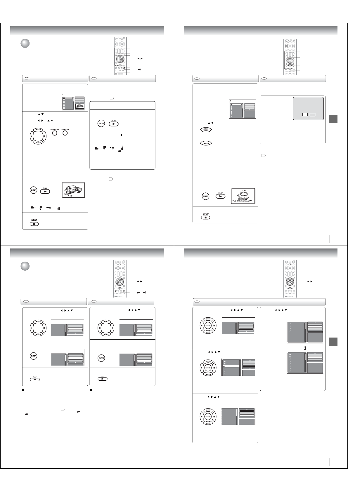
Advanced playback
F
F
M
M
F
F
M
M
w
MP3/WMA/JPEG/DivX® and Audio CD
operation (Continued)
You can select your desired JPEG le on the le menu and picture menu.
The selected JPEG le is automatically adjusted to the TV screen. (When the
aspect ratio of the JPEG le is different to the TV screen, the black bar will
appear at the top and bottom, or the both sides of the TV screen.)
CD CD
JPEG CD playback
Load a JPEG disc in the disc slot.
1
A le browser screen
will appear on the
2
screen.
Press / to select the le.
To display a thumbnail list, press DVD MENU.
3
Press
/ or / to select the desired le.
(To return to a le browser, press TOP MENU.)
• When PLAY is pressed after displaying the
le browser, playback begins
starting from the rst le. In this case,
le is a JPEG le, the rst JPEG le is played
back. If the rst le is a DivX
®
le is played back.
DivX
If the rst le is an MP3/WMA le, only MP3/
WMA les are played back in order. If there is
no le at a root directory, playback does not
begin automatically.
Press ENTER or PLAY. The selected picture
appears on the screen.
4
Rotating an image
You can rotate an image by 90 degrees.
Press ANGLE during playback of the image.
”, “ ”, “ ” or “ ” appears on the
“
screen.
Press STOP to end playback.
5
The le browser appears on the
screen. If you want to watch the other
le, repeat steps 3 ~ 4.
/Picture-01.JPG
Picture-01
Picture-02
Picture-03
Picture-04
Picture-05
Picture-06
Picture-07
Picture-08
automatically
®
le, the rst
Select Files
Repeat :Off
Mode :Off
JPEG Preview
W: 2048 H: 1536
if the rst
Slide show playback
The slide show enables you to view pictures ( les) one
after another automatically.
Preparation:
• Set “JPEG Interval” setting to “5 Seconds”, “10 Seconds”
or “15 Seconds”
Select your desired starting le for the slide
show in the step 3 on left.
1
Press ENTER or PLAY to start slide show
from the selected le.
2
• If you press PA USE during the slide show, the slide
show stops temporary. “
screen.
If the picture appears upside down or sideways,
press ANGLE repeatedly until it’s right side up.
“
”, “ ”, “ ” or “ ” appears on the screen.
Press PLAY or SKIP
show.
• When the slide show playback nished, the le list
appears.
• To stop the slide show, press STOP. The le list
appears.
Notes:
• Zoom function also can be used in viewing JPEG les.
See “Zooming”
• During JPEG playback, you cannot use Jump and A-B
Repeat functions.
47
.
” appears brie y on the
again to resume the slide
32
.
STOP
TOP MENU
DVD MENU
V/W/ /
ENTER
PAUSE
PLAY
SKIP
ANGLE
CD
DivX® CD playback
Load a disc on which DivX® les have been
recorded in the disc slot.
1
A le browser screen will appear on the
screen.
2
Press / to select le.
3
• When PLAY has been pressed after displaying
the le browser, playback begins automatically
starting from the rst le. In this case, if the
rst le is a JPEG le, the rst JPEG le is
played back. If the rst le is a
the rst DivX
le is an MP3/WMA le, only MP3/WMA le
are played back in order. If there is no le
at a root directory, playback does not begin
automatically.
Press ENTER or PLAY. The selected DivX®
movie will be played back on the screen.
4
Press STOP to end playback.
The le browser appears on the
5
/Movie-01.DIVX
Movie-01
Movie-02
Movie-03
Movie-04
Movie-05
Movie-06
Movie-07
Movie-08
®
le is played back. If the rst
screen. If you want to watch the
other le, repeat steps 3 ~ 4.
DivX® le,
CD
Playing DivX® VOD content
DivX® VOD content is protected by DRM (Digital Rights
Management) system. This restricts playback of content
to speci c registered devices.
If the incorrect DRM le
is loaded, “Authorization
Select Files
Error This player is not
Repeat :Off
Mode :Off
authorized to play this
video.” will appear on the
JPEG Preview
screen.
When you attempt to play
®
VOD, the number
DivX
of plays is limited and the
right message will appear on the screen. If you wish to
play it, select “Yes”.
• If the number of plays goes over the limit, then
“Rental Expired” will be displayed. In this case, the
le will not be played.
Notes:
• In order to play DivX
need to register the unit with registration code. See page
49
.
• Depending on the recording conditions of DivX® le, you
may not be able to use FF, REV or JUMP function.
®
VOD content on this unit, you rst
STOP
V/W
ENTER
PLAY
View DivX¨ VOD Rental
This rental has 5 views left.
Do you want to use one
of your 5 views now?
NoYes
Advanced playback
40
Advanced playback
Repeat and program playback using le
browser
CD CD
Repeat playback (CD)
In the le browser, press / / / to select
“Repeat” during stop mode.
1
older-1
older-2
P3-1
P3-2
Press ENTER to select “Track” or “All”.
2
older-1
older-2
P3-1
P3-2
Press PLAY.
3
To resume normal playback
Select Repeat : “Off” in step 2.
Notes:
• The repeat function is canceled when you eject the disc or
turn the power off.
• In case of Audio CD, the function of A-B Repeat can be
used. See “A-B Repeat playback”
• Track repeat function is canceled whenever SKIP
The unit automatically starts repeat
playback after nishing the current
track.
is pressed.
Select Files
Repeat :Off
Mode :Off
-
Select Files
Repeat :Track
Mode :Off
Select Mode : “Off” in step 2.
Note:
The Randam function is canceled when you eject the disc or
.
33
turn the power off.
or
V/W/ /
ENTER
PLAY
SKIP /
Random playback (CD)
Folder-1
Folder-2
MP3-1
MP3-2
Folder-1
Folder-2
MP3-1
MP3-2
-
-
/ / / to select
In the le browser, press
“Mode” during stop mode.
1
Press ENTER to select “Random”.
2
Press PLAY.
3
To resume normal playback
The Random playback will start.
Select Files
Repeat :Off
Mode :Off
Select Files
Repeat :Off
Mode :Random
CD
Program playback (CD)
In the le browser, press / / / to select
“Edit Mode”, then press ENTER.
1
Folder-1
Repeat :Off
Folder-2
Mode :Off
MP3-1
MP3-2
When “Edit Mode” is black color,
you can mark the les which you want
to add into Program list.
Press
/ / / to select le you want to add
2
into the program list.
Press ENTER. Selected le was
Repeat this procedure to select the
Press /// to select “Add To Program”.
Then press ENTER. All marked les are added
3
into the program list.
Folder-1
Folder-2
MP3-1
MP3-2
MP3-3
WMA-1
marked.
other les.
Folder-1
Folder-2
MP3-1
MP3-2
MP3-3
WMA-1
When you nish storing the les
which you want into the Program
list, select “Edit Mode” and press
ENTER to release edit mode.
Edit Mode
Repeat :Off
Mode :Off
Edit Mode
JPEG Previe
Edit Mode
Program View
Add To Program
JPEG Preview
V/W/ /
ENTER
PLAY
Press
/ / /
to select “Program View”,
MP3-1
MP3-2
MP3-3
WMA-3
Folder-1
Folder-2
MP3-1
MP3-2
MP3-3
WMA-1
WMA-2
WMA-3
Edit Mode
Browser View
Clear Program
JPEG Preview
Edit Mode
Program View
Add To Program
JPEG Preview
then press ENTER. Program View shows only
4
the programed les that you have added in step
2.
Program View
Browser View
In the Program View, press PLAY. The les
start to playback in programmed order that
5
were added by you.
To remove le from program list in Stop mode
In the Edit Mode, switch to Program View. Select
le you want to remove, then press ENTER.
Select “Clear Program” and press ENTER.
Marked le is removed from program list.
Note:
The program function is canceled when you eject the disc or
turn the power off.
41
Advanced playback
42
43
Page 14
Function setup
Customizing the function settings
You can change the default settings of the DVD mode to customize
performance to your preference.
DVD
VCD
Setting procedure
CD
Press SETUP during stop mode.
1
The following on-screen display appears.
Press Vor W to select the desired section,
.
then press
2
First option will be highlighted. Press
to select the desired option.
3
Then press or ENTER. The selectable
settings will appear.
4
Parental : Off
DRC : Off
E.B.L. : Off
Menu : English
Set Password
QSound : On
TV Screen : 4:3
Subtitle : English
Output : Interlace
Display : On
Audio : English
DivX(R) VOD
Picture Mode : Auto
JPEG Interval : 5 Seconds
Screen Saver : On
Parental : Off
DRC : Off
Menu : English
TV Screen : 4:3
Set Password
QSound : On
Subtitle : English
Display : On
Output : Interlace
Audio : English
Picture Mode : Auto
DivX(R) VOD
JPEG Interval : Off
Parental : Off
DRC : Off
Menu : English
TV Screen : 4:3
Set Password
QSound : On
Subtitle : English
Display : On
Output : Interlace
Audio : English
Picture Mode : Auto
DivX(R) VOD
JPEG Interval : Off
Parental : Off
DRC : Off
Menu : English
TV Screen 4:3
Set Password
QSound : On
Subtitle : English
Display 4:3
Output : Interlace
Audio : English
Picture Mode : Auto
DivX(R) VOD
JPEG Interval : Off
5
6
Vor W
SETUP
ENTER
/
V/W/
RETURN
Change the selection using Vor W, by
referring to the corresponding pages
Press ENTER to save the setting.
• Repeat steps 3 and 5 to change
other option.
• To select another section, go
back to step 2 by pressing
repeatedly.
To clear SETUP screen, press SETUP or
RETURN.
Setting details
46
~ 49.
Section
Option
Menu
Subtitle
Audio
TV Screen
Display
Picture Mode
JPEG Interval
DRC
Parental
Password
DivX(R) VOD
Details
To select the language of “Menu”, “Subtitle” and
“Audio” if more than one language are available on
the disc.
To select a picture size according to the aspect
ratio of your TV.
To turn On or Off the operational status display on
the screen.
To select a preferred picture mode from “Video”,
“Film” or “Auto”.
To select a preferred setting for the slide show
playback.
To select On or Off for DRC (Dynamic Range Control).
To select a preferred parental level for the
parental setting.
To change the password.
To display your 8-character registration
code.
Page
46
46
47
48
48
49
Function setup
44
Function setup
Customizing the function settings (Continued)
Setting details
Parental : Off
DRC : Off
E.B.L. : Off
Menu : English
Set Password
QSound : On
TV Screen : 4:3
Subtitle : English
Output : Interlace
Display : On
Audio : English
DivX(R) VOD
Picture Mode : Auto
JPEG Interval : 5 Seconds
Screen Saver : On
Menu, Subtitle, Audio
You can select the language of “Menu”, “Subtitle” and
“Audio” if more than one languages are recorded onto
the disc.
English, Francais, Espanol:
The selected language will be heard or seen.
Other:
Other language can be selected (see “Language
51
).
code list”
Original (Audio):
The unit will select the rst priority language of
each disc.
Off (Subtitle):
Subtitles do not appear.
Notes:
• If the selected language is not recorded on the disc, the
rst-priority language is selected.
• If you want to change the OSD language, you can
perform it by TV SETUP MENU
21
.
TV Screen
You have the following screen sizes to choose from:
4:3
Select this mode when connecting to a
conventional TV. When playing back a wide
screen-DVD disc, it displays the wide picture
with black bands at the top and bottom of
screen.
4:3
It displays the wide picture on the whole screen
with left and right edges automatically cut off.
Note:
If the DVD disc is not formatted in the Pan & scan
style, it will display 4:3 style.
(Letter box):
(Pan & scan):
Display
On screen display can be switched on or off when you
press any buttons.
On: On screen displays appear when you press
the buttons (factory setting).
Off: On screen displays do not appear when you
press any buttons.
Parental : Off
DRC : Off
Menu : English
TV Screen : 4:3
Set Password
QSound : On
Subtitle : English
Display : On
Output : Interlace
Audio : English
Picture Mode : Auto
DivX(R) VOD
JPEG Interval : Off
Picture Mode
There are two types of source content in pictures
recorded in DVD video discs: lm content (pictures
recorded from lms at 24 frames per second) and
video content (video signals recorded at 30 frames per
second). Make this selection according to the type of
content being viewed.
Auto: Select this selection normally.
The DVD player automatically detects
source content, lm or video of
playback source, and converts that
signal in the progressive output format
in an appropriate method.
Film: The DVD player converts lm content
pictures in the progressive output
format appropriately. Suitable for
playback of lm content pictures. The
progressive output feature will be most
effective under this selection.
Video: The DVD player lters video signal and
converts it in the progressive output
format appropriately.
Suitable for playback of video content
pictures.
Note:
Depending on the disc, pictures may be cut off or
doubled. In this case, select “Video”.
JPEG Interval
You can continuously playback all JPEG les
automatically.
After the selection below, the disc will start playback on
JPEG les which have been recorded.
Off:
Plays back one le at a time.
5 Seconds:
Plays back images in the form of a slide show at
5 second intervals.
10 Seconds:
Plays back images in the form of a slide show at
10 second intervals.
15 Seconds:
Plays back images in the form of a slide show at
15 second intervals.
45
Function setup
46
47
Page 15
Function setup
Customizing the function settings (Continued)
Setting details
Parental : Off
E.B.L. : Off
DRC : Off DRC : Off
Set Password
TV Screen : 4:3
Output : Interlace
Display : On
DivX(R) VOD
Picture Mode : Auto
JPEG Interval : 5 Seconds
Screen Saver : On
DRC
DRC (Dynamic Range Control) enables you to control
the dynamic range so as to achieve a suitable sound
for your equipment.
Off:
It plays back at the recording level on the disc.
On:
Loud sound such as explosion is toned down
slightly when played back. This is suitable when
it is connected to a stereo.
Notes:
• This function works only during playback of Dolby Digital
recorded discs.
• The level of Dynamic Range Reduction may differ
depending on DVD video disc.
48
Menu : English
E.B.L. : Off
Parental : Off
QSound : On
Subtitle : English
TV Screen : 4:3
Password : Change
Audio : English
Display : On
DivX(R) VOD : Display
Picture Mode : Auto
JPEG Interval : 5 Seconds
Screen Saver : On
Parental control setting
Some discs are speci ed as not suitable for children.
Such discs can be limited not to playback with the unit.
or to select “Parental”, then press
1) Press
ENTER. “Enter Password” screen will appear.
2) Press “0000” using Number buttons (0–9).
(Please note, this is pre-setting password of this
unit). Then press ENTER. The parental level list
will appear.
• Level Off: The parental control setting does not
function.
• Level 8: All DVD software can be played
back.
• Level 1: DVD software for adults cannot be
played back.
3) Press or to select from the level 1 to level 8.
The limitation will be more severe as the level
number is lower. Then press ENTER.
Notes:
• Depending on the discs, the unit cannot limit
playback.
• Some discs may not be encoded with speci c rating
level information though its disc jacket says “adult.”
For those discs, the age restriction will not work.
• The password is required every time when you
change the parental level.
• If you input a wrong number, press CANCEL.
Q Set the new password
1) Press
or to select “Password”, then press
ENTER. “Enter Current Password” screen will
appear.
2) Press Number buttons (0–9) to input the current
password (If the password has not been set yet
after you purchase this unit, it is “0000”).
3) Then press ENTER. “Enter New Password” screen
will appear. Press Number buttons (0–9) to input
the new password.
4) Press ENTER. Now your new password has been
set. Be sure to remember this number!
If you forget the password.
1) Press EJECT to remove the disc.
2) While holding 7 down on the remote control and
then press STOP on the unit. “Password Clear”
appears on the screen. Now the password has
been returned to the initial value (“0000”).
®
DivX
VOD
®
In order to play DivX
content on this unit, you rst need to register the unit
with your DivX
generating a DivX
submit to your provider.
Press
press ENTER. Your 8-character registration code is
displayed. Make a note of the code as you will need
it when you register with a DivX
Then press ENTER to select Done.
Note:
If each setup (pages 46 ~ 49) has completed, the unit
can always work under the same condition (especially
with DVD discs).
Each setup will be retained in the memory even if you
turn the power off.
VOD (Video On Demand)
®
VOD content provider. You do this by
®
VOD registration code, which you
or to select “DivX(R) VOD”. Then
®
VOD provider.
Function setup
49
Function setup
Temporary cancel the rating level by
DVD disc
Depending on the DVD disc, the disc may try to temporarily cancel the rating
level that you have set.
It is up to you to decide whether to cancel the rating level or not.
DVD
Temporary cancel the rating level by DVD disc
Load a DVD disc.
1
If the DVD disc has been designed to
temporarily cancel the Rating level, the screen
2
which follows the “Reading” screen will
change, depending on which disc is played.
If you select “YES” with the ENTER key,
password input screen will then appear.
• If “NO” is selected, press EJECT to remove
the disc.
Enter the password with Number buttons
(0–9). Then press ENTER.
3
4
To exit from the entry, press
RETURN.
Enter Password
Playback will commence if the entered
password is correct.
Note:
This temporary cancellation of rating level will be kept until the
disc is ejected.
When the disc is ejected, the original rating level will be set
again automatically.
EJECT
0–9
ENTER
RETURN
Others
Language code list
Enter the appropriate code number for the initial settings “Menu”, “Subtitle” and/or “Audio” 46.
Language Name Code Language Name Code Language Name Code Language Name Code
Abkhazian 1112 Fiji 1620 Lingala 2224 Singhalese 2919
Afar 1111 Finnish 1619 Lithuanian 2230 Slovak 2921
Afrikaans 1116 French 1628 Macedonian 2321 Slovenian 2922
Albanian 2927 Frisian 1635 Malagasy 2317 Somali 2925
Amharic 1123 Galician 1722 Malay 2329 Spanish 1529
Arabic 1128 Georgian 2111 Malayalam 2322 Sundanese 2931
Armenian 1835 German 1415 Maltese 2330 Swahili 2933
Assamese 1129 Greek 1522 Maori 2319 Swedish 2932
Aymara 1135 Greenlandic 2122 Marathi 2328 Tagalog 3022
Azerbaijani 1136 Guarani 1724 Moldavian 2325 Tajik 3017
Bashkir 1211 Gujarati 1731 Mongolian 2324 Tamil 3011
Basque 1531 Hausa 1811 Nauru 2411 Tatar 3030
Bengali; Bangla 1224 Hebrew 1933 Nepali 2415 Telugu 3015
Bhutani 1436 Hindi 1819 Norwegian 2425 Thai 3018
Bihari 1218 Hungarian 1831 Oriya 2528 Tibetan 1225
Breton 1228 Icelandic 1929 Panjabi 2611 Tigrinya 3019
Bulgarian 1217 Indonesian 1924 Pashto, Pushto 2629 Tonga 3025
Burmese 2335 Interlingua 1911 Persian 1611 Turkish 3028
Byelorussian 1215 Irish 1711 Polish 2622 Turkmen 3021
Cambodian 2123 Italian 1930 Portuguese 2630 Twi 3033
Catalan 1311 Japanese 2011 Quechua 2731 Ukrainian 3121
Chinese 3618 Javanese 2033 Rhaeto-Romance 2823 Urdu 3128
Corsican 1325 Kannada 2124 Romanian 2825 Uzbek 3136
Croatian 1828 Kashmiri 2129 Russian 2831 Vietnamese 3219
Czech 1329 Kazakh 2121 Samoan 2923 Volapük 3225
Danish 1411 Kirghiz 2135 Sanskrit 2911 Welsh 1335
Dutch 2422 Korean 2125 Scots Gaelic 1714 Wolof 3325
English 1524 Kurdish 2131 Serbian 2928 Xhosa 3418
Esperanto 1525 Laothian 2225 Serbo-Croatian 2918 Yiddish 2019
Estonian 1530 Latin 2211 Shona 2924 Yoruba 3525
Faroese 1625 Latvian, Lettish 2232 Sindhi 2914 Zulu 3631
Others
50
51
Page 16
Others
Troubleshooting
Use the following check list for troubleshooting when you have problems with your unit. Consult your local dealer
or service outlet if problems persist.
Be sure all connections are properly made when using with other units.
SYMPTOMS POSSIBLE SOLUTIONS PAGE
POWER
TV/DVD does not operate.
TV BROADCAST RECEPTION
Poor sound or No sound.
Poor picture or No picture.
Poor reception on some
channels.
Poor color or no color.
Picture wobbles or drifts.
No CATV reception.
Horizontal or diagonal bars on
screen.
No reception above channel 13.
TV shuts off.
Closed - Caption is not
activated.
Display is not shown in your
language.
• Make sure the connection of AC cord is secured.
• Try another AC outlet.
• Unplug unit, then plug it back in.
• Station or Cable TV may have problems, try another station.
• Check Volume adjustments.
• Check for sources of possible interference.
• Station or Cable TV may have problems, try another station.
• Check antenna or Cable TV connections, reorient antenna.
• Check for sources of possible interference.
• Check picture control adjustments.
• Station or Cable TV may have problems, try another station.
• Station signal is weak, reorient antenna to receive weaker station.
• Check for sources of possible interference.
• Station or Cable TV may have problems, try another station.
• Make sure channels are set into memory.
• Check picture control adjustments.
• Check antenna or Cable TV connections, reorient antenna.
• Check for sources of possible interference.
• Station or Cable TV may have problems, try another station.
• Make sure channels are set into memory.
• Cable TV company is scrambling signal.
• Check antenna or Cable TV connections, reorient antenna.
• Check all Cable TV connections.
• Set TV/CABLE selection to the CABLE position.
• Station or Cable TV system problems, try another station.
• Check antenna or Cable TV connections, reorient antenna.
• Check for sources of possible interference.
• Make sure TV/CABLE selection is in the appropriate position.
• If antenna is used, check UHF antenna connections.
• No broadcast on station tuned.
• Auto shut off feature worked.
• Sleep Timer is set.
• Power interrupted.
• TV station experiencing problems or program tuned is not closed
captioned. Try another channel.
• Check Cable TV connection or VHF/UHF antenna, reposition or
rotate antenna.
• Press CLOSED CAPTION button to turn on the closed caption
decoder.
• Select proper language in the menu options. 21
14,15
14,15
14,15
14,15
14,15
20
23
23
54
23
54
26
23
14
54
23
22
26
54
23
22
15
22
23
54
22
14
22
23
24
23
25
SYMPTOMS POSSIBLE SOLUTIONS PAGE
DVD
Playback doesn’t start.
No picture. • TV/DVD selector is not set correctly. 29
No sound.
Picture is distorted during fast
reverse/forward playback.
Stopping playback, search,
slowmotion play, repeat play, or
program play, etc. cannot be
performed.
No on-screen display. • Set Display to On. 46
The unit or remote operation key
is not functioning.
Playback does not start when
the title is selected.
Audio soundtrack and/or subtitle
language is not changed when
-
-
you playback a DVD.
No subtitle.
Angle cannot be changed. • Multi-angles are not recorded on the DVD disc. 35
“” appears on the screen. • The function is prohibited with the unit or the disc. 31
REMOTE CONTROL
The remote control does not
function.
• No disc is loaded.
• The disc may be dirty. Clean up the disc.
• The unit cannot play CD-ROMs, etc.
• Check the input selector of the ampli er is set properly.
• The unit is in the special playback mode.
• Select the correct Audio Input/Output position on AV ampli er.
• The picture will be distorted occasionally. -
• Some discs may not do some of the functions. -
• Turn off the unit and unplug the AC power cord for several minutes,
then replug it.
• Check the RATING LEVEL setup. 48
• Multilingual language is not recorded on the DVD disc. 36
• Some discs have no subtitles.
• Subtitles are cleared. Press the SUBTITLE button.
• Aim the remote control at the remote sensor.
• Operate within approx. 5 meters or reduce the light in the room.
• Clear the path of the beam.
• The batteries are weak. Replace the batteries.
• Check the batteries are inserted correctly.
29
7
8
31
18
-
Others
36
13
52
Others
Reception disturbances
Most types of television interference can be remedied by adjusting the height and position of the
VHF/UHF antenna. Outdoor antennas are recommended for best results. The most common types
of television interference are shown below. If one of these symptoms appear when the TV/DVD is
connected to a Cable TV system, the disturbance may be caused by the local Cable TV company
broadcast.
IGNITION
Black spots or horizontal streaks may appear, the picture may utter or
drift. Usually caused by interference from automobile ignition systems,
neon lamps or AC powered tools and appliances such as drills or hair
dryers.
GHOSTS
Ghosts are caused by the television signal following two paths. One is
the direct path and the other is re ected by tall buildings, hills or other
large objects. Changing the direction or position of the antenna may
improve the reception.
SNOW
If the TV/DVD is located far from the TV station, in a fringe reception
area where the signal is weak, small dots may appear in the picture.
If the signal is extremely weak, the installation of a larger external
antenna may be necessary.
RADIO FREQUENCY INTERFERENCE (RFI)
Caused by two-way radios, this type of interference produces moving
ripples or diagonal streaks in the picture. Some cases may cause a
loss of contrast in the picture. Changing the direction and position of
the antenna or installing an RFI lter may improve the picture.
CARE AND MAINTENANCE
To prevent re or shock hazard, disconnect the TV/DVD from the power source before cleaning.
Use caution when cleaning or wiping the plastic parts.
54
Speci cations
General
Power supply AC 120V 60Hz (with supplied AC adapter)
Power consumption Operation: 50 W, Stand by: 1 W (with supplied AC adapter)
Weight 13.2 lbs (6.0 kg)
Dimensions
Operating temperature 5°C-40°C (41°F-104°F)
Operating humidity Less than 80% RH (No condensation)
Television
LCD panel 15-inch diagonal (Screen size is approximate.)
Display method Color TFT LCD
Number of pixels 1024 (Horizontal) x 768 (Vertical)
Tuner type F-Synth
Receiving channels
Antenna input VHF/UHF 75
Speaker 1-1/2 x 2-11/16 inches (38.1 x 68.6 mm), 8 x 2
Audio output power 1.5W + 1.5W
DVD/CD Player
Signal system NTSC
Applicable disc
Pickup 1-Lens, 2-Beams System
Input/Output
S-Video input
ColorStream video input
Video input 1.0 V (p-p), 75 , negative sync., pin jack x 2
Audio input –8 dBm, 50 k, negative sync., pin jack (L/R) x 2
Digital audio output (Coaxial) 0.5 V (p-p), 75 , pin jack x 1
Headphone ø3.5mm stereo mini jack x 1
Accessories
Remote control (DC-LB1) ............................................. 1
Batteries (R03/AAA) ..................................................... 2
AC adapter ................................................................... 1
AC cord (for AC adapter) .............................................. 1
300-75 matching transformer..................................... 1
Owner’s manual (this booklet) ...................................... 1
• This model complies with the above speci cations.
• Designs and speci cations are subject to change without notice.
• This model may not be compatible with features and/or speci cations that may be added in the future.
Width: 18-3/4 inches (476 mm)
Height: 13-15/16 inches (353.5 mm)
Depth: 9-1/16 inches (230 mm)
VHF: 2-13
UHF: 14-69
CATV: 1-125 (4A, A-5~A-1, A~I, J~W, W+1~W+84)
1. DVD (12cm, 8cm)
2. CD (12cm, 8cm)
(Y) 1.0 V (p-p), 75 , negative sync., Mini DIN 4-pin x 1
(C) 1.0 V (p-p), 75
(Y) 1.0 V (p-p), 75 , negative sync., pin jack x 1
B, PR) 0.7 V (p-p), 75 , pin jack x 2
(P
53
Others
55
Page 17
Others
Limited Canadian Warranty
for Toshiba Brand Flat Panel Televisions
Toshiba of Canada Limited (“TCL”) makes the following limited warranties to original consumers in Canada. THESE LIMITED
WARRANTIES EXTEND TO THE ORIGINAL CONSUMER PURCHASER OR ANY PERSON RECEIVING THIS TOSHIBA
BRAND FLAT PANEL TELEVISION (the “TELEVISION(S)” or “Television(s)”) AS A GIFT FROM THE ORIGINAL
CONSUMER PURCHASER AND TO NO OTHER PURCHASER OR TRANSFEREE.
TELEVISIONS PURCHASED IN CANADA, AND USED ANYWHERE OUTSIDE OF CANADA INCLUDING, WITHOUT
LIMITATION, THE UNITED STATES AND MEXICO, ARE NOT COVERED BY THESE WARRANTIES.
TELEVISIONS PURCHASED ANYWHERE OUTSIDE OF CANADA, INCLUDING, WITHOUT LIMITATION, THE UNITED
STATES AND MEXICO, AND USED IN CANADA, ARE NOT COVERED BY THESE WARRANTIES.
Limited One (1) Year Warranty on Parts and Labour
Subject to the more limited warranty if the Television is used for any
commercial or business purposes as set out below, TCL warrants
the Television and its parts against material defects in materials or
workmanship that result in the Television failing for a period of one (1)
year after the date of original retail purchase. DURING THIS PERIOD,
TCL WILL, AT TCL’S OPTION, REPAIR OR REPLACE A DEFECTIVE
PART WITH A NEW OR REFURBISHED PART WITHOUT CHARGE
TO YOU FOR PARTS OR LABOUR.
(a) FOR TELEVISIONS 32 INCHES OR LESS: YOU MUST
DELIVER THE ENTIRE TELEVISION TO A TCL TELEVISION
AUTHORIZED SERVICE PROVIDER (“ASP”). YOU MUST PAY
FOR ALL TRANSPORTATION AND INSURANCE CHARGES
FOR THE TELEVISION TO AND FROM THE ASP.
(b) FOR TELEVISIONS OVER 32 INCHES: During this period,
ASP personnel will come to your home when warranty service is
required. Depending on the type of repair required, the service will
either be performed in your home or the Television will be taken
to an ASP for repair and returned to your home at no cost to you.
IN-HOME SERVICE ONLY APPLIES WITHIN 100 KILOMETERS
OF AN ASP. IF YOU ARE NOT WITHIN 100 KILOMETERS OF
AN ASP, YOU MUST DELIVER THE ENTIRE TELEVISION TO
AN ASP. YOU MUST PAY FOR ALL TRANSPORTATION AND
INSURANCE CHARGES FOR THE TELEVISION TO AND FROM
THE ASP.
Limited Warranty for Commercial Units
TCL warrants Televisions that are used for any commercial or business
purposes as follows: all parts are warranted against material defects
in materials or workmanship that result in the Television failing for a
period of ninety (90) days after the date of original retail purchase.
DURING THIS PERIOD, TCL WILL, AT TCL’S OPTION, REPAIR OR
REPLACE THE DEFECTIVE PART WITH A NEW OR REFURBISHED
PART WITHOUT CHARGE TO YOU.
(c) FOR TELEVISIONS 32 INCHES OR LESS: YOU MUST DELIVER
THE ENTIRE TELEVISION TO AN ASP. YOU MUST PAY FOR
ALL TRANSPORTATION AND INSURANCE CHARGES FOR
THE TELEVISION TO AND FROM THE ASP.
(d) FOR TELEVISIONS OVER OVER 32 INCHES: During this
period, ASP personnel will come on-site when warranty service is
required. Depending on the type of repair required, the service will
either be performed on-site or the Television will be taken to an
ASP for repair and returned at no cost to you. ON-SITE SERVICE
ONLY APPLIES WITHIN 100 KILOMETERS OF AN ASP. IF
YOU ARE NOT WITHIN 100 KILOMETERS OF AN ASP, YOU
MUST DELIVER THE ENTIRE TELEVISION TO AN ASP. YOU
MUST PAY FOR ALL TRANSPORTATION AND INSURANCE
CHARGES FOR THE TELEVISION TO AND FROM THE ASP.
Rental Units
The warranty for Television rental units begins with the date of rst
rental or thirty (30) days from the date of shipment to the rental rm,
whichever comes rst.
Your Responsibility
THE ABOVE WARRANTIES ARE SUBJECT TO THE FOLLOWING
CONDITIONS:
(1) You must provide your bill of sale or other proof of purchase.
(2) All warranty servicing of this Television must be performed by an
ASP.
(3) The warranties from TCL are effective only if the Television is
(i) purchased as new and unopened from TCL or from TCL’s
authorized distributors, dealers or resellers (“ADR’s”) and (ii)
located/operated in Canada.
(4) Labour charges for set installation, setup, adjustment of customer
controls, and installation or repair of antenna systems are not
covered by these warranties. Reception problems caused by
inadequate antenna systems are your responsibility.
(5) Warranties extend only to material defects in materials or
workmanship as limited above, and do not extend to:
a. Service, repairs or replacement made necessary by accident,
misuse, abuse, moisture, liquids, dust, dirt, neglect, accident,
damage, 24/7 applications, improper installation, improper
operation, improper cleaning, improper maintenance, normal wear
and tear, screen burn or image retention caused by prolonged
display of static images and/or phosphor aging, or any other
external cause or event, act or omission outside the control of TCL,
including re, theft, acts of God, alteration, power failures, power
surges or power shortages, lightning, other electrical faults, or
repairs, modi cations or replacements by persons other than those
authorized by TCL to service the Television;
b. Replacement of missing, discarded or lost parts, the provision of
retro ts, or preventive maintenance;
c. Repair of damage that is cosmetic only or does not affect the
Television functionality, such as wear and tear, scratches and
dents;
d. Service on Toshiba-branded accessory items (such accessory
items may be covered by their own warranty);
e. Service on third party products or service made necessary by use
of incompatible third party products;
f. Service made necessary by the simultaneous use of this Television
and connected equipment;
g. Modi cations to the Television not approved in writing by TCL, and
service made necessary by the use or installation of non-Toshiba
modi cations to the Television;
h. Service of a Television on which the TOSHIBA label or logo, rating
label or serial number have been defaced or removed;
i. On-site service and repair of the Television; and
j. Damage to the Television caused by failure to follow the
speci cations, User manuals or guides as to usage and/or storage.
56
Disclaimer and Limitation of Remedy
TO THE EXTENT NOT PRECLUDED BY LAW, ALL OTHER
EXPRESS AND IMPLIED WARRANTIES, CONDITIONS AND
REPRESENTATIONS FOR THIS TELEVISION, INCLUDING THE
IMPLIED WARRANTIES, CONDITIONS AND REPRESENTATIONS
OF MERCHANTABILITY AND FITNESS FOR A PARTICULAR
PURPOSE, ARE HEREBY DISCLAIMED AND EXCLUDED.
IF THE APPLICABLE LAW, STATUTORY OR OTHERWISE,
PRECLUDES THE EXCLUSION OF ANY IMPLIED WARRANTIES,
CONDITIONS AND REPRESENTATIONS THEN SUCH IMPLIED
WARRANTIES, CONDITIONS AND REPRESENTATIONS ARE
OTHERWISE LIMITED IN DURATION TO THE TERM OF THIS
EXPRESS WRITTEN LIMITED WARRANTY. TO THE EXTENT
NOT PRECLUDED BY LAW, STATUTORY OR OTHERWISE, THIS
WRITTEN WARRANTY SUPERCEDES AND SPECIFICALLY
DISCLAIMS ANY OTHER WARRANTY, CONDITION OR
REPRESENTATION NOT STATED IN THIS WARRANTY, WHETHER
MADE BY TCL, TOSHIBA CORPORATION, THEIR AFFILIATES,
ADRs AND ASPs AND WHETHER MADE ORALLY OR IN WRITING
(INCLUDING ANY STATEMENT IN ANY BROCHURE, PRESS
RELEASE, ANNOUNCEMENT, ADVERTISEMENT, POINT OF SALE
DISPLAY, ETC.).
YOU MUST READ AND FOLLOW ALL SET-UP AND USAGE
INSTRUCTIONS IN THE APPLICABLE USER GUIDES AND/OR
MANUALS. IF YOU FAIL TO DO SO, THIS TELEVISION MAY
NOT FUNCTION PROPERLY AND YOU MAY SUFFER DAMAGE.
THIS WARRANTY WILL NOT COVER ANY SERVICE THAT IS
REQUIRED, IN PART OR IN WHOLE, AS A RESULT OF ANY
FAILURE TO FOLLOW THE SET-UP AND USAGE INSTRUCTIONS.
THIS WARRANTY DOES NOT APPLY AND SHALL BE VOID AND
UNENFORCEABLE IF THE TELEVISION IS OPENED, SERVICED,
OR REPAIRED BY PERSONS OTHER THAN THOSE AUTHORIZED
BY TCL TO SERVICE OR REPAIR THE TELEVISION.
IF THE TELEVISION FAILS TO WORK AS WARRANTED ABOVE,
YOUR SOLE AND EXCLUSIVE REMEDY SHALL BE REPAIR OR
REPLACEMENT OF THE DEFECTIVE PART. IN NO EVENT WILL
TCL, TOSHIBA CORPORATION, THEIR AFFILIATES, ADRs OR
ASPs (THE “RELATED PARTIES”) BE LIABLE TO YOU OR ANY
THIRD PARTY FOR ANY DAMAGES, MONEY, REIMBURSEMENT,
COSTS OR EXPENSES. THIS LIMITATION APPLIES TO
DAMAGES, MONEY, REIMBURSEMENT, COSTS OR EXPENSES
OF ANY KIND WHATSOEVER INCLUDING ANY DIRECT OR
INDIRECT DAMAGES, DAMAGE TO PROPERTY OR PERSON,
LOST PROFITS, LOST SAVINGS, INCONVENIENCE OR OTHER
SPECIAL, INCIDENTAL, EXEMPLARY OR CONSEQUENTIAL
DAMAGES, WHETHER FOR BREACH OF WARRANTY, BREACH
OF CONTRACT, TORT (INCLUDING NEGLIGENCE), UNDER A
STATUTE OR UNDER ANY OTHER LAW OR FORM OR ACTION,
OR WHETHER ARISING OUT OF THE USE OF OR INABILITY TO
USE THE TELEVISION, EVEN IF ANY OF THE RELATED PARTIES
HAS BEEN ADVISED OF THE POSSIBILITY OF SUCH DAMAGES
OR OF ANY CLAIM BY ANY OTHER PARTY.
No person, agent, distributor, dealer or company is authorized
to change, modify or extend the terms of these warranties in any
manner whatsoever.
Arbitration and Dispute Resolution
To the extent not precluded by law, any claim, dispute, controversy
or disagreement (whether for breach of warranty, breach of contract,
tort (including negligence), under a statute or under any other law or
form of action) against any of the Related Parties arising out of, or
otherwise relating to: (i) this warranty; (ii) the Television; (iii) any oral
or written representations, statements, brochures, press releases,
advertising, announcement, point of sale display, or promotional
material relating to the Television; (iv) the relationships that result
from this warranty, (the foregoing claims, disputes controversies and
disagreements are collectively referred to as the “Dispute”), shall
be referred to and resolved by nal and binding arbitration (to the
exclusion of the courts). To the extent not precluded by law, you agree
to waive any right that you may have to commence or participate in
any representative or class proceeding against the Related Parties
relating to any Dispute. If and where applicable and to the extent
not precluded by law, you further agree to opt out of any such
representative or class proceedings.
Arbitration of any Dispute will be conducted in the forum and in the
manner as agreed to between you and TCL. Failing such agreement,
the arbitration will be conducted by one arbitrator pursuant to the laws
and rules relating to arbitration generally in force in the jurisdiction in
which you reside at the time that the Dispute arises. To the extent not
precluded by law, no claim, dispute, controversy or disagreement of
any other person may be joined or combined with any Dispute by you,
without the prior written consent of TCL.
Critical Applications
The Television you have purchased is not designed for any “critical
applications.” “Critical applications” means life support systems,
medical applications, connections to implanted medical devices,
commercial transportation, nuclear facilities or systems or any other
applications where Television failure could lead to injury to persons or
loss of life or catastrophic property damage.
IF THE CUSTOMER USES THE TELEVISION IN ANY CRITICAL
APPLICATION, THE CUSTOMER – AND NOT TCL, ITS AFFILIATES,
ADRs OR ASPs – ASSUME SOLE AND FULL RESPONSIBILITY
FOR SUCH USE. TCL RESERVES THE RIGHT TO REFUSE TO
SERVICE ANY TELEVISION USED IN A CRITICAL APPLICATION.
TCL, ITS AFFILIATES, ADRs AND ASPs HEREBY DISCLAIM ANY
AND ALL LIABILITY, DAMAGES AND CONSEQUENCES ARISING
OUT OF THE SERVICE OR REFUSAL TO SERVICE SUCH
TELEVISION AND FURTHER DISCLAIM ANY AND ALL LIABILITY,
CONSEQUENCES AND DAMAGES THAT MAY ARISE OR
RESULT FROM THE USE OF THE TELEVISION IN ANY CRITICAL
APPLICATIONS.
General Provisions
If and to the extent that any provision of this limited warranty should
generally be found to be unenforceable, the unenforceable provision
shall be severed from the warranty and deemed not to form part
of the warranty. The remaining provisions of this warranty shall
be and remain valid and enforceable. If and to the extent that any
provision of this limited warranty as it relates to any of the Related
Parties is found to be invalid or unenforceable in respect of that
party (the “Excluded Party”), the Excluded Party shall be deemed
to be severed or excluded from the provision, and the provision shall
remain valid, enforceable and applicable in respect of the other or
remaining Related Parties.
To the extent permitted by law, this limited warranty shall be governed
and construed in accordance with the laws of Ontario.
If there is any inconsistency between this limited warranty, on the one
hand, and any statement in the packaging of the Television or in any
other document enclosed with, or used in the context of the promotion
or sale of, the Television, on the other hand, the provisions of this
limited warranty shall prevail.
How to Obtain Warranty Services
If, after following all of the operating instructions in this manual and
checking the “Troubleshooting” section, you nd that service is
needed:
(1) To nd the nearest ASP, visit TCL’s web site at www.toshiba.ca, or
call toll free 1-800-268-3404
(2) Present your bill of sale or other proof of purchase to the ASP.
For additional information, visit TCL’s website at www.toshiba.ca
OthersOthers
57
MEMO
MEMO
Page 18
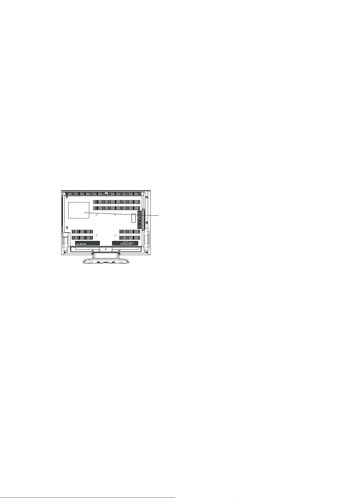
CAUTION
THIS
LCD COLOR TELEVISION
TO ENSURE PROPER USE OF THIS PRODUCT, PLEASE READ THIS SERVICE MANUAL CAREFULLY AND RETAIN FOR FUTURE REFERENCE. SHOULD THE UNIT REQUIRE MAINTENANCE,
CONTACT AN AUTHORIZED SERVICE LOCATION-SEE SERVICE PROCEDURE.
USE OF CONTROLS, ADJUSTMENTS OR THE PERFORMANCE OF PROCEDURES OTHER THAN
THOSE SPECIFIED HEREIN MAY RESULT IN HAZARDOUS RADIATION EXPOSURE.
TO PREVENT DIRECT EXPOSURE TO LASER BEAM, DO NOT TRY TO OPEN THE ENCLOSURE.
VISIBLE LASER RADIATION MAY BE PRESENT WHEN THE ENCLOSURE IS OPENED. DO NOT
STARE INTO BEAM.
Location of the required Marking
The rating sheet and the safety caution are on the rear of the unit.
EMPLOYS A LASER SYSTEM.
CERTIFICATION: COMPLIES WITH FDA
RADIATION PERFORMANCE STANDARDS,
21 CFR SUBCHAPTER J.
PREPARATION OF SERVICING
The laser diode used for a pickup head may be destroyed with external static electricity.
Moreover, even if it is operating normally after repair, when static electricity discharge is received at the
time of repair, the life of the product may be shortened.
Please perform the following measure against static electricity, be careful of destruction of a laser diode
at the time of repair.
• Place the unit on a workstation equipped to protect against static electricity, such as conductive mat.
• Soldering iron with ground wire or ceramic type is used.
• A worker needs to use a ground conductive wrist strap for body.
A1-1
Page 19
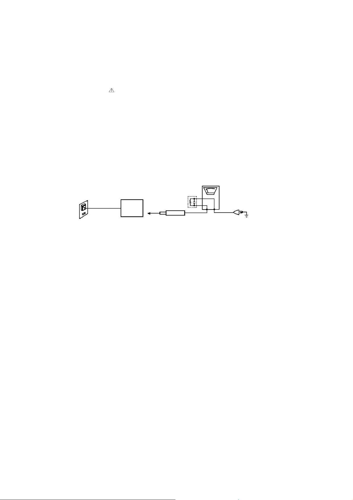
IMPORTANT SERVICE SAFETY INFORMATION
Safety precautions to be followed during servicing:
1.
Parts marked with an
are critical parts for safety. Replace only with the one described in the parts
list.
2.
Before returning the DVD product to the customer, make the appropriate leakage current check or
resistance measurements to ensure that exposed parts are properly insulated from the supply circuit.
A leakage current check is recommended for this unit. Plug the AC line cord directly into a 120V 60Hz AC
outlet (do not use an isolation transformer for this check). Use a leakage current tester (Fig. 1) or a
metering system which complies with Underwriters Laboratories (UL 1492P). Measure for current from all
exposed metal parts of the cabinet to a known earth ground: particularly, any exposed metal part having a
return path to the chassis. Any current measured must not exceed 0.5mA. Any measurement not within
the limits outlined above are indicative of a potential shock hazard and corrective action must be taken
before returning the unit to the customer.
(Reading should not be above 0.5mA)
Leakage Current Tester
KNOWN EARTH
GROUND
2-Blade polarized
type cord set
PRODUCTUNDERTEST
Test all exposed
metal surfaces
1.5K ohm
0.15 μF
TESTPROBE
Fig. 1 AC Leakage Test
A1-2
Page 20

IMPORTANT SAFEGUARDS
1.
READ INSTRUCTIONS
All the safety and operating instructions should be read before the unit is operated.
2.
RETAIN INSTRUCTIONS
The safety and operating instructions should be retained for future reference.
3.
HEED WARNINGS
All warnings on the unit and in the operating instructions should be adhered to.
4.
FOLLOW INSTRUCTIONS
All operating and use instructions should be followed.
5.
CLEANING
Unplug this unit from the wall outlet before cleaning. Do not use liquid cleaners or aerosol cleaners. Use a damp
cloth for cleaning.
6.
ATTACHMENTS
Do not use attachments not recommended by the unit’s manufacturer as they may cause hazards.
7.
WATER AND MOISTURE
Do not use this unit near water. For example, near a bathtub, washbowl, kitchen sink, or laundry tub, in a wet
basement, or near a swimming pool.
8.
ACCESSORIES
Do not place this unit on an unstable cart, stand, tripod, bracket, or table. The
unit may fall, causing serious injury, and serious damage to the unit. Use only
with a cart, stand, tripod, bracket, or table recommended by the manufacturer.
8A.
An appliance and cart combination should be moved with care. Quick stops,
excessive force, and uneven surfaces may cause the appliance and cart
combination to overturn.
9.
VENTILATION
Slots and openings in the cabinet and in the back or bottom are provided for ventilation, to ensure reliable
operation of the unit, and to protect it from overheating. These openings must not be blocked or covered. The
openings should never be blocked by placing the unit on a bed, sofa, rug, or other similar surface. This unit
should never be placed near or over a radiator or heat source. This unit should not be placed in a built-in
installation such as a bookcase or rack unless proper ventilation is provided or the manufacturer’s instructions
have been adhered to.
10.
POWER SOURCES
This unit should be operated only from the type of power source indicated on the rating plate. If you are not sure
of the type of power supply to your home, consult your appliance dealer or local power company. For units
intended to operate from battery power, or other sources, refer to the operating instructions.
11.
GROUNDING OR POLARIZATION
This unit is equipped with a polarized alternating-current line plug (a plug having one blade wider than the other).
This plug will fit into the power outlet only one way. This is a safety feature. If you are unable to insert the plug
fully into the outlet, try reversing the plug. If the plug should still fail to fit, contact your electrician to replace your
obsolete outlet. Do not defeat the safety purpose of the polarized plug. If your unit is equipped with a 3-wire
grounding-type plug, a plug having a third (grounding) pin, this plug will only fit into a grounding-type power
outlet. This too, is a safety feature. If you are unable to insert the plug into the outlet, contact your electrician to
replace your obsolete outlet. Do not defeat the safety purpose of the grounding-type plug.
POWER-CORD PROTECTION
12.
Power-supply cords should be routed so that they are not likely to be walked on or pinched by items placed upon
or against them, paying particular attention to cords at plugs, convenience receptacles, and the point where they
exit from the appliance.
LIGHTNING
13.
To protect your unit from a lightning storm, or when it is left unattended and unused for long periods of time,
unplug it from the wall outlet and disconnect the antenna or cable system. This will prevent damage to the unit
due to lightning and power line surges.
POWER LINES
14.
An outside antenna system should not be located in the vicinity of overhead power lines or other electric light or
power circuits, or where it can fall into such power lines or circuits. When installing an outside antenna system,
extreme care should be taken to keep from touching such power lines or circuits, as contact with them might be
fatal.
OVERLOADING
15.
Do not overload wall outlets and extension cords, as this can result in a risk of fire or electric shock.
16.
OBJECT AND LIQUID ENTRY
Do not push objects through any openings in this unit, as they may touch dangerous voltage points or short out
parts that could result in fire or electric shock. Never spill or spray any type of liquid into the unit.
PORTABLE CART WARNING
(symbol provided by RETAC)
S3126A
A1-3
Page 21

IMPORTANT SAFEGUARDS (CONTINUED)
OUTDOOR ANTENNA GROUNDING
17.
If an outside antenna or cable system is connected to the unit, be sure the antenna or cable system is grounded
so as to provide some protection against voltage surges and built-up static charges. Section 810 of the National
Electrical Code, ANSI/NFPA 70, provides information with respect to proper grounding of the mast and supporting
structure, grounding of the lead-in wire to an antenna discharge unit, size of grounding conductors, location of
antenna discharge unit, connection to grounding electrodes, and requirements for the grounding electrode.
SERVICING
18.
Do not attempt to service this unit yourself as opening or removing covers may expose you to dangerous voltage
or other hazards. Refer all servicing to qualified service personnel.
DAMAGE REQUIRING SERVICE
19.
Unplug this unit from the wall outlet and refer servicing to qualified service personnel under the following
conditions:
a.
When the power-supply cord or plug is damaged.
b.
If liquid has been spilled, or objects have fallen into the unit.
c.
If the unit has been exposed to rain or water.
d.
If the unit does not operate normally by following the operating instructions. Adjust only those controls that
are covered by the operating instructions, as an improper adjustment of other controls may result in
damage and will often require extensive work by a qualified technician to restore the unit to its normal
operation.
e.
If the unit has been dropped or the cabinet has been damaged.
f.
When the unit exhibits a distinct change in performance, this indicates a need for service.
REPLACEMENT PARTS
20.
When replacement parts are required, be sure the service technician uses replacement parts specified by the
manufacturer or those that have the same characteristics as the original parts.
Unauthorized substitutions may result in fire, electric shock or other hazards.
SAFETY CHECK
21.
Upon completion of any service or repairs to this unit, ask the service technician to perform safety checks to
determine that the unit is in proper operating condition.
WALL OR CEILING MOUNTING
22.
The product should be mounted to a wall or ceiling only as recommended by the manufacturer.
HEAT
23.
The product should be situated away from heat sources such as radiators, heat registers, stoves, or other
products (including amplifiers) that produce heat.
DISC TRAY
24.
Keep your fingers well clear of the disc tray as it is closing. It may cause serious personal injury.
CONNECTING
25.
When you connect the product to other equipment, turn off the power and unplug all of the equipment from the
wall outlet. Failure to do so may cause an electric shock and serious personal injury. Read the owner's manual of
the other equipment carefully and follow the instructions when making any connections.
SOUND VOLUME
26.
Reduce the volume to the minimum level before you turn on the product. Otherwise, sudden high volume sound
may cause hearing or speaker damage.
SOUND DISTORTION
27.
Do not allow the product output distorted sound for a longtime. It may cause speaker overheating and fire.
HEADPHONES
28.
When you use the headphones, keep the volume at a moderate level. If you use the headphones continuously
with high volume sound, it may cause hearing damage.
LASER BEAM
29.
Do not look into the opening of the disc tray or ventilation opening of the product to see the source of the laser
beam. It may cause sight damage.
DISC
30.
Do not use a cracked, deformed, or repaired disc. These discs are easily broken and may cause serious
personal injury and product malfunction.
NOTE TO CATV SYSTEM INSTALLER
31.
This reminder is provided to call the CATV system installer’s attention to Article 820-40 of the NEC that provides
guidelines for proper grounding and, in particular, specifies that the cable ground shall be connected to the
grounding system of the building, as close to the point of cable entry as practical.
A1-4
Page 22
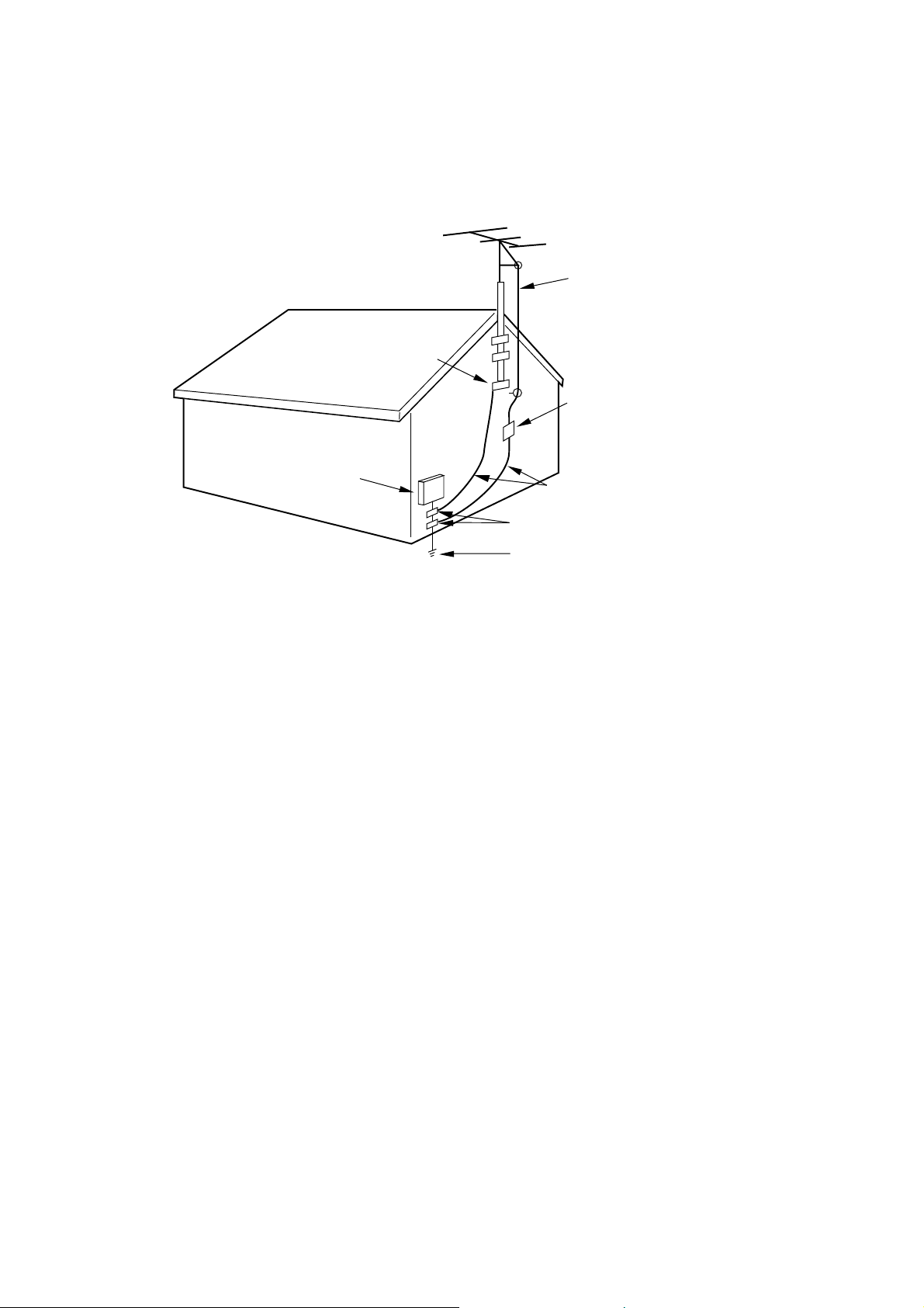
EXAMPLE OF ANTENNA GROUNDING AS PER THE NATIONAL ELECTRICAL CODE
ANTENNA LEAD
IN WIRE
GROUND
CLAMP
ANTENNA
DISCHARGE UNIT
(NEC SECTION 810-20)
ELECTRIC SERVICE
EQUIPMENT
GROUNDING CONDUCTORS
(NEC SECTION 810-21)
GROUND CLAMPS
NEC-NATIONAL ELECTRICAL CODE
S2898A
POWER SERVICE GROUNDING
ELECTRODE SYSTEM
(NEC ART 250, PART H)
A1-5
Page 23
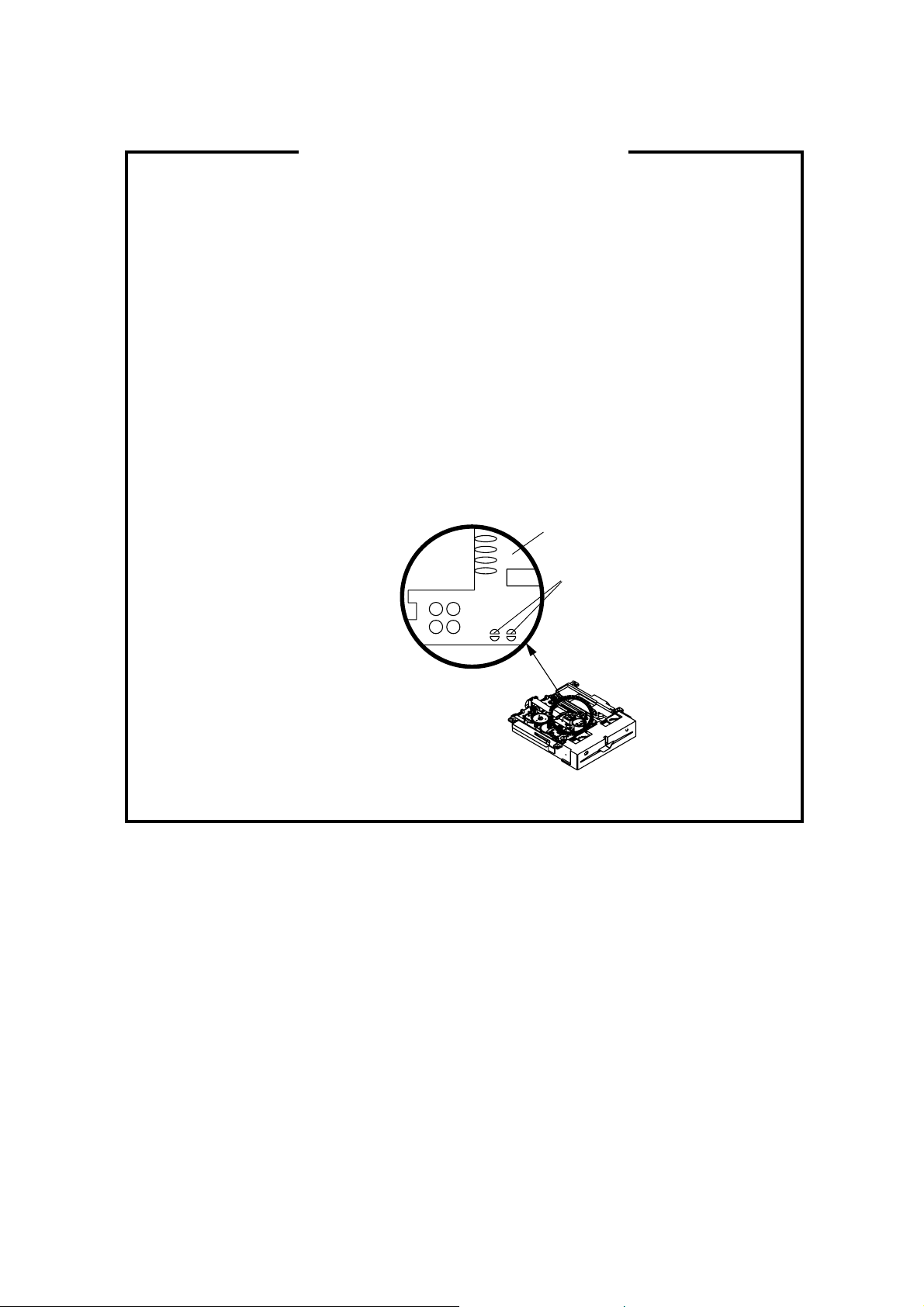
WHEN REPLACING DVD DECK
[ When removing the DVD Deck ]
Before removing Pick Up PCB and DVD MT PCB connector, the short circuit the position shown in Fig.
1 using a soldering iron. If you remove the DVD Deck with no soldering, the Laser may be damaged.
[ When installing the DVD Deck ]
Remove all the soldering on the short circuit position after the connection of Pick Up PCB and DVD
MT PCB connector.
NOTE
Before your operation, please read “PREPARATION OF SERVICING”.
•
Use the Lead Free solder.
•
Manual soldering conditions
•
• Soldering temperature: 320 ± 20˚C
• Soldering time: Within 3 seconds
• Soldering combination: Sn-3.0Ag-0.5Cu
When Soldering/Removing of solder, use the draw in equipment over the Pick Up Unit to keep the
•
Flux smoke away from it.
Pick Up PCB
Short circuit using a
soldering iron.
Fig. 1
A1-6
Page 24
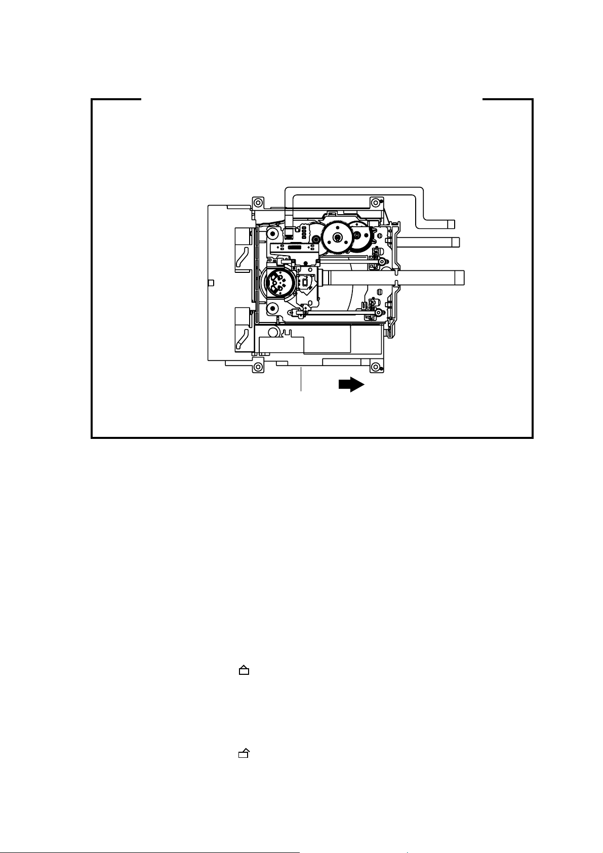
DISC REMOVAL METHOD AT NO POWER SUPPLY
1.
Remove the Back Cabinet and Angle Deck. (Refer to item 1 of the DISASSEMBLY INSTRUCTIONS.)
2.
Slide the Belt Loading toward the arrow direction by hand to release the lock. (Refer to Fig. 1)
3.
Take out the Disc from the DVD Deck. Be careful not to scratch on the Disc.
DVD Deck
Belt Loading
Fig. 1
PARENTAL CONTROL - RATING LEVEL
4 DIGIT PASSWORD CANCELLATION
If the stored 4 digit password in the Rating Level menu needs to be cancelled, please follow the steps below.
Turn Unit ON.
1.
Set the DVD to the Stop Mode.
2.
Check that ‘No disc’ is displayed on the screen.
3.
Press and hold the ‘STOP’ button on the front panel.
4.
Simultaneously press and hold the ‘7’ key on the remote control unit.
5.
Hold both keys for more than 2 seconds.
6.
The On Screen Display message ‘PASSWORD CLEAR’ will appear.
7.
The 4 digit password has now been cleared.
8.
TRAY LOCK
The disk cannot be taken out by setting the Tray Lock, please follow the steps below.
Turn Unit ON.
1.
Set the DVD to the Stop Mode.
2.
Press it in order of ‘SETUP’, ‘SUBTITLE’, ‘3’, ‘AUDIO’ and ‘0’ key of a remote control unit.
3.
The On Screen Display message ‘ ‘ will appear.
4.
The Tray Lock has now been set up.
5.
To unlock the Tray Lock, please follow the steps below.
Turn Unit ON.
1.
Set the DVD to the Stop Mode.
2.
Press it in order of ‘SETUP’, ‘SUBTITLE’, ‘3’, ‘AUDIO’ and ‘0’ key of a remote control unit.
3.
The On Screen Display message ‘ ‘ will appear.
4.
The Tray Lock has now been cleared.
5.
A1-7
Page 25

TABLE OF CONTENTS
• GREEN PRODUCT PROCUREMENT
• LEAD-FREE SOLDER
• OWNER'S MANUAL
CAUTION .....................................................................................................................
IMPORTANT SERVICE SAFETY INFORMATION .....................................................
IMPORTANT SAFEGUARDS .....................................................................................
WHEN REPLACING DVD DECK ................................................................................
DISC REMOVAL METHOD AT NO POWER SUPPLY ...............................................
PARENTAL CONTROL - RATING LEVEL .................................................................
TRAY LOCK ................................................................................................................
TABLE OF CONTENTS ..............................................................................................
GENERAL SPECIFICATIONS ....................................................................................
DISASSEMBLY INSTRUCTIONS
1.REMOVAL OF MECHANICAL PARTS AND P.C. BOARDS ................................
2.REMOVAL OF DVD DECK PARTS ......................................................................
3.REMOVAL AND INSTALLATION OF FLAT PACKAGE IC ..................................
SERVICE MODE LIST .................................................................................................
SERVICING FIXTURES AND TOOLS ........................................................................
RE-WRITE FOR DVD FIRMWARE .............................................................................
CONFIRMATION OF CHECK SUM ............................................................................
WHEN REPLACING EEPROM (MEMORY) IC ...........................................................
ELECTRICAL ADJUSTMENTS ..................................................................................
TROUBLESHOOTING GUIDE ....................................................................................
BLOCK DIAGRAMS
DVD ..........................................................................................................................
AV ............................................................................................................................
POWER ....................................................................................................................
SCALER ...................................................................................................................
PRINTED CIRCUIT BOARDS
SCALER ...................................................................................................................
AV/OPERATION/REMOCON/SIDE JACK ...............................................................
DVD MT/OPERATION2 ...........................................................................................
BACK LIGHT/SW .....................................................................................................
SCHEMATIC DIAGRAMS
MPEG/MICON/DSP/RF_AMP ..................................................................................
MEMORY .................................................................................................................
AUDIO/VIDEO ..........................................................................................................
MOTOR DRIVE ........................................................................................................
REGULATOR2 .........................................................................................................
OPERATION2 ..........................................................................................................
JACK ........................................................................................................................
TUNER/STEREO .....................................................................................................
AV SWITCH .............................................................................................................
SOUND ....................................................................................................................
POWER ....................................................................................................................
OPERATION/SIDE JACK/REMOCON .....................................................................
MICON .....................................................................................................................
SCALER ...................................................................................................................
LVDS ........................................................................................................................
SYNC SEPA .............................................................................................................
REGULATOR ...........................................................................................................
INVERTER ...............................................................................................................
SW ...........................................................................................................................
INTERCONNECTION DIAGRAM ................................................................................
WAVEFORMS .............................................................................................................
MECHANICAL EXPLODED VIEWS ...........................................................................
DVD DECK EXPLODED VIEW ...................................................................................
MECHANICAL REPLACEMENT PARTS LIST ..........................................................
DVD DECK REPLACEMENT PARTS LIST ................................................................
ELECTRICAL REPLACEMENT PARTS LIST ............................................................
A1-1
A1-2
A1-3~A1-5
A1-6
A1-7
A1-7
A1-7
A2-1
A3-1~A3-6
B1-1~B1-4
B2-1, B2-2
B3-1, B3-2
C-1
C-2
C-2
C-3
C-3
D-1~D-4
E-1~E-11
F-1, F-2
F-3, F-4
F-5, F-6
F-7, F-8
G-1, G-2
G-3~G-6
G-7, G-8
G-9, G-10
H-1, H-2
H-3, H-4
H-5, H-6
H-7, H-8
H-9, H-10
H-11, H-12
H-13, H-14
H-15, H-16
H-17, H-18
H-19, H-20
H-21, H-22
H-23, H-24
H-25, H-26
H-27, H-28
H-29, H-30
H-31, H-32
H-33, H-34
H-35, H-36
H-37, H-38
H-39, H-40
I-1~I-4
J1-1~J1-3
J2-1
K1-1, K1-2
K2-1
K3-1~K3-5
A2-1
Page 26
GENERAL SPECIFICATIONS
G-1 TV
System
G-2 DVD System
G-3 Tuning
System
G-4 Signal
G-5 Power
LCD LCD Size / Visual Size 15.0 inch / 380.0mmV
LCD Type Color TFT LCD
Number of Pixels 1024(H) x 768(V)
View Range Left/Right 70/70 degree
Up/Down 60/65 degree
Color System NTSC
Speaker 2 Speaker
Position Front
Size 1.5 x 2.7 inch
Impedance 8 ohm
Sound Output Max 1.5W + 1.5W
10%(Typical) --Color System NTSC
Disc
Disc Diameter 120 mm , 80 mm
Drive DSM-2
Search speed Fwd 4 step
Rev 4 step
Slow speed Fwd 1/7 -1/2 times
Rev 1/7 -1/2 times
Broadcasting System US System M
Tuner and System 1Tuner
Receive CH Destination US(W/CABLE)
CH Coverage 2~69, 4A, A-5~A-1, A~I, J~W, W+1~W+84
Intermediate Picture(FP) 45.75MHz
Frequency Sound(FS) 41.25MHz
FP-FS 4.50MHz
Preset CH No
Stereo/Dual TV Sound US-Stereo
Tuner Sound Muting Yes
Video Signal Input Level 1 V p-p/75 ohm
Output Level --
S/N Ratio (Weighted) --
Horizontal Resolution at DVD Mode --
RGB Signal Output Level -Audio Signal Input Level -8.0dBm/50k ohm
Output Level --
Digital Output Level 0.5 V p-p/75 ohm
S/N Ratio at DVD (Weighted) --
Harmonic Distortion --
Frequency Response : at DVD --
at Video CD --
at SVCD --
Power Source AC 120V, 60Hz
DC -Power Consumption at AC Adapter 50W at 120V 60Hz
Stand by (at AC Adapter) 1W at 120V 60Hz
Energy Star Yes
Per Year -- kWh/Year
Protector Power Fuse Yes
Safety Circuit Yes
IC Protector(Micro Fuse) Yes
DVD,
Actual 2-45 times (DVD)
4-40 times (CD)
Actual 2-45 times (DVD)
4-40 times (CD)
Actual --
Actual --
--
at CD --
at DC --
A3-1
Page 27

GENERAL SPECIFICATIONS
G-6 Regulation
G-7 Temperature
G-8 Operating Humidity
G-9 Clock and
Timer
G-10 Remote
Control
Clock No
Sleep Timer Max Time 120 Min
On Timer Program No
Off Timer Program No
Wake Up Timer No
Timer Back-up (at Power Off Mode) more than -- Min Sec
Unit RC-LB
Glow in Dark Remocon Yes
Remocon Format ORION
Format NEC
Custom Code 71-8E h
Power Source Voltage(D.C) 3V
Total Keys 47 Key
Keys Power Yes
Safety cUL(E650065_00)
Radiation IC
Laser --
Operation
Storage
Step 10 Min
UM size x pcs UM-4 x 2 pcs
1 Yes
2 Yes
3 Yes
4 Yes
5 Yes
6 Yes
7 Yes
8 Yes
9 Yes
0 Yes
Play Yes
Stop Yes
Search+ Yes
Search- Yes
Skip+ Yes
Skip- Yes
Slow+ Yes
Slow- Yes
Pause/Still/Step Yes
Recall Yes
TV/DVD Yes
Cancel Yes
Audio Select Yes
Angle Yes
Subtitle Yes
Top Menu Yes
Setup/ Menu Yes
DVD Menu Yes
Return Yes
Up / CH Up Yes
Down / CH Down Yes
Vol Down Yes
Vol Up Yes
Left Yes
Right Yes
Enter Yes
Play Mode Yes
Closed Caption Yes
Input Select Yes
Repeat A-B Yes
o
+5
C ~ +40oC
o
-20
C ~ +60oC
Less than 80% RH
A3-2
Page 28

G-11 Features
(TV)
GENERAL SPECIFICATIONS
Zoom/ Quick View Yes
Mute Yes
Eject Yes
Sleep Yes
Jump Yes
Game Yes
Freeze frame No
Auto Shut Off Yes
Auto Search No
Power On Memory No
Comb Filter Yes
2D
Game Position Yes
Auto Setup(Language/CH Program) No
Picture Setting Yes
Picture Preference Yes
Brightness , Contrast , Color Yes
Tint Yes
Sharpness Yes
Color Temperature Yes
Cable Clear No
Audio MTS Yes
Tone Control (Bass/Treble/Balance) Yes
Stable Sound No
Surround Yes
BBE No
SRS WOW (SRS 3D/Focus/Tru Bass) No
Valiable Audio Out No
Tuning CH Program Yes
TV/Cable Yes
ADD/DELETE Yes
Label CH Label No
Video Label No
Favorite CH No
V-Chip No
Type ---RRT Setup No
Lock Hotel Lock No
Channel Lock No
Video Lock No
Panel Lock No
OSD Language
Closed Caption
CC Advanced No
Picture Size No
Picture Scroll No
Cinema Mode No
Aspect
Backlight No
PFC(Power Factor circuit)
Freeze frame No
PIP/POP No
Direct Input Selection No
Game Position Yes
PC Monitor Input No
HDMI Input No
Component Input Yes
720×480i (4:3) Yes (60Hz)
720×480i (16:9) Yes (60Hz)
720×480p (4:3) Yes (60Hz)
720×480p (16:9) Yes (60Hz)
720×576i (4:3) No
English French Spanish
Yes
No
No
A3-3
Page 29

Features
(DVD)
G-12 Accessories
GENERAL SPECIFICATIONS
720×576i (16:9) No
720×576p (4:3) No
720×576p (16:9) No
1280×720p No
1920×1080i No
Tray Lock Yes
WMA Yes
JPEG Yes
Video CD Playback Yes
SVCD Playback
Overlay Graphics And Text No
Command List No
Entry Point Jump No
MP3 Playback Yes
Divx Playback Yes
DMF Support No
Digital Out (Dolby Digital) Yes
(MPEG) Yes
(PCM) Yes
(DTS) Yes
Down Mix Out (Dolby Digital) Yes
(DTS) No
3D Surround No
Closed Caption Yes
Screen Saver No
Audio DAC 192kHz / 24bit
Owner's Manual Language English/French
w/Guarantee Card Yes
Remote Control Unit Yes
Rod Antenna
Poles --
Terminal -Loop Antenna
Terminal -U/V Mixer
DC Car Cord (Center+) No
Guarantee Card No
Warning Sheet No
Circuit Diagram No
Antenna Change Plug No
Service Facility List No
Important Safeguard No
Dew/AHC Caution Sheet No
Quick Set-up Sheet No
Battery Yes
UM size x pcs UM-4 x 2 pcs
OEM Brand No
AC Adapter Yes
AC Cord (for AC Adapter) Yes
AV Cord (2Pin-1Pin)
Registration Card Yes
300 ohm to 75 ohm Antenna Adapter Yes
Sheet Information (Return) Yes(Canada version)
No
No
No
No
No
A3-4
Page 30

GENERAL SPECIFICATIONS
G-13 Interface
G-14 Set Size
G-15 Weight
G-16 Carton
G-17 Material
G-18 Environment
Switch Top Power (Tact) Yes
Channel Up Yes
Channel Down Yes
Volume Up Yes
Volume Down Yes
Play Yes
Eject Yes
Skip+, Search+ Yes
Skip-, Search- Yes
Still/Pause No
Stop Yes
Main Power SW No
Input Select No
Rear Main Power SW No
Indicator Power/Stand-By Yes (Green / Red)
On Timer No
Terminals Rear Video Input 1 RCA x 1
Audio Input 1 RCA x 2 (L/MONO, R)
S- Input 1 No
Video Output No
Audio Output No
Component Yes
Euro Scart(21Pin) No
PC Monitor Input No
Digital Audio Output Coaxial (DVD Only)
DC Jack (Center +)
VHF/UHF Antenna Input
AC Outlet No
Side Video Input 2 RCA x 1
Audio Input 2 RCA x 2 (L/MONO, R)
S- Input 2 Yes
Other Terminal Headphone
Approx. W x D x H (mm) 476 x 230 x 353.5
w/o Handle, Stand Approx. W x D x H (mm)
Net (Approx.) 6.0kg (13.2 lbs)
Net w/o Handle, Stand (Approx.) 4.5kg (9.9 lbs)
Gross (Approx.) 8.0kg (17.6 lbs)
Master Carton No
Content --- Sets
Material --- / ---
Dimensions W x D x H(mm) ---
Description of Origin ---
Gift Box Material Single/White
W/Color Photo Label No
Dimensions W x D x H(mm) 575x322x441
Description of Origin Yes
Drop Test
Height (cm) 80
Container Stuffing (40' container) 740
Cabinet Front PS 94V0 DECABROM
Rear PS 94V0 DECABROM
Jack Panel --
PCB Non-Halogen Demand No
Eyelet Demand No
Environmental standard requirement (by buyer) Green procurement of TOSHIBA
Pb-free Phase3 (Phase3A)
Measures for Whisker Yes
Yes
F Type
476 x 78.5 x 312.5
Natural Dropping At 1 Corner / 3 Edges / 6
Sets/40' container
Surfaces
A3-5
Page 31

GENERAL SPECIFICATIONS
G-19 AC Power Adapter
Power Requirement AC 120V 60Hz
Max Power Consumption (Adapter Only) at AC 65 W
DC Output DC Jack : DC12V 4.5A
Dimension Approx. W x D x H (mm) 150 x 72 x 43
Weight Approx. 450g
Provided Accessories
A3-6
Page 32

DISASSEMBLY INSTRUCTIONS
1. REMOVAL OF MECHANICAL PARTS
AND P.C. BOARDS
1-1: HINGE ASS'Y (Refer to Fig. 1-1)
1.
Remove the 3 screws 1.
2.
Remove the Stand in the direction of arrow (A).
3.
Remove the 8 screws 2.
4.
Remove the Stand Angle in the direction of arrow (B).
5.
Remove the 4 screws 3.
6.
Remove the Hinge Ass'y in the direction of arrow (C).
2
3
1
1
1
Stand
(B)
(A)
1-2: BACK CABINET (Refer to Fig. 1-2)
1.2.Remove the 9 screws 1.
Remove the Back Cabinet in the direction of arrow.
1
1
1
1
Back Cabinet
1
1
(C)
Stand Angle
Hinge Ass'y
Fig. 1-1
1
1
1
1-3: ANGLE BACK (Refer to Fig. 1-3)
1.2.Remove the 3 screws 1.
Remove the Angle Back in the direction of arrow.
1
1
Angle Back
2
3
2
3
2
1
Fig. 1-3
1-4: DVD DECK (Refer to Fig. 1-4)
1.
Short circuit the position shown in Fig. 1-4 using a
soldering iron. If you remove the DVD Deck with no
soldering, the Laser may be damaged.
2.
Disconnect the following connectors:
(CP2301, CP2302 and CP2303).
3.
Remove the 4 screws 1.
4.
Remove the DVD Deck in the direction of arrow (A).
5.
Remove the 2 screws 2.
6.
Remove the Angle Deck-R in the direction of arrow (B).
7.
Remove the 2 screws 3.
8.
Remove the Angle Deck-L in the direction of arrow (C).
Short circuit using a
soldering iron.
3
Pick Up PCB
Angle Deck-R
1
1
2
2
(B)
3
(C)
1
Angle Deck-L
1
DVD Deck
Fig. 1-2
B1-1
CP2303
CP2302
CP2301
(A)
Fig. 1-4
Page 33

DISASSEMBLY INSTRUCTIONS
NOTE
Before your operation, please read “PREPARATION OF
1.
SERVICING”.
Use the Lead Free solder.
2.
Manual soldering conditions
3.
• Soldering temperature: 320 ± 20˚C
• Soldering time: Within 3 seconds
• Soldering combination: Sn-3.0Ag-0.5Cu
When Soldering/Removing of solder, use the drawing
4.
equipment over the Pick Up Unit to keep the Flux smoke
away from it.
When installing the DVD Deck, remove all the soldering on
5.
the short circuit position after the connection of Pick Up
PCB and DVD PCB connector.
1-5: BACK LIGHT PCB (Refer to Fig. 1-5)
1.
Disconnect the following connectors:
(CP3802, CP7001, CP7002, CP7003 and CP7004).
2.
Remove the 4 screws 1.
3.
Remove the Shield Inverter and Back Light PCB in the
direction of arrow.
Shield Inverter
CP3802
1
1
1
1
Back Light PCB
CP7002
CP7004
CP7001
CP7003
Fig. 1-5
1
1
1
Shield FFC
DVD MT PCB
CP4203
CP3803
1
Shield MPEG
CP203
1-7: SCALER PCB (Refer to Fig. 1-7)
1.
Disconnect the following connectors:
(CP202, CP204, CP801, CP3804 and CP7201).
2.
Remove the 2 screws 1.
3.
Remove the Shield Scaler in the direction of arrow (A).
4.
Remove the 2 screws 2.
5.
Remove the 2 screws 3.
6.
Remove the Scaler PCB in the direction of arrow (B).
2
CP202
1
(A)
2
(B)
3
1
CP204
3
CP7201
Shield Scaler
Scaler PCB
CP801
CP3804
Fig. 1-6
1-6: DVD MT PCB (Refer to Fig. 1-6)
1.
Disconnect the following connectors:
(CP203, CP3803 and CP4203).
2.
Remove the 4 screws 1.
3.
Remove the Shield FFC, Shield MPEG and DVD MT PCB
in the direction of arrow.
Fig. 1-7
B1-2
Page 34

DISASSEMBLY INSTRUCTIONS
1-8: SIDE JACK PCB (Refer to Fig. 1-8)
1.
Disconnect the following connectors:
(CP301, CP4402 and CP4403).
2.
Remove the 2 screws 1.
3.
Remove the Side Jack PCB in the direction of arrow (A).
4.
Remove the Shield Jack-Side and Plate Jack-Side in the
direction of arrow (B).
1
1
Plate Jack-Side
Shield Jack-Side
(B)
(A)
Side Jack PCB
CP4402
CP4403
CP301
Fig. 1-8
1-9: AV PCB (Refer to Fig. 1-9)
1.
Remove the 2 screws 1.
2.
Remove the screw 2.
3.
Remove the screw 3.
4.
Remove the Plate Jack-1 and Shield Jack-1 in the direction
of arrow (A).
5.
Remove the 2 screws 4.
6.
Remove the 3 screws 5.
7.
Remove the Plate Jack-2 and Shield Jack-2 in the direction
of arrow (B).
8.
Remove the 5 screws 6.
9.
Remove the AV PCB in the direction of arrow (C).
OPERATION PCB/REMOCON PCB (Refer
1-10:
to Fig. 1-10)
1.
Disconnect the following connector: (CP2251).
2.
Remove the 2 screws 1.
3.
Remove the Holder PCB-DVD in the direction of arrow (A).
4.
Remove the 2 screws 2.
5.
Remove the Operation 2 PCB in the direction of arrow (B).
6.
Remove the 2 screws 3.
7.
Remove the Holder PCB-TV in the direction of arrow (C).
8.
Remove the 2 screws 4.
9.
Remove the Operation PCB in the direction of arrow (D).
10.
Remove the 2 screws 5.
11.
Remove the Remocon PCB in the direction of arrow (E).
5
5
(E)
Remocon PCB
Holder PCB-TV
Operation PCB
3
(C)
3
1
(A)
1
(B)
Holder PCB-DVD
Operation 2 PCB
Fig. 1-10
4
CP2251
(D)
2
2
4
AV PCB
Plate Jack-2
Shield Jack-2
6
6
(C)
4
5
5
5
(B)
6
4
1
3
2
(A)
6
6
1
Plate Jack-1
Shield Jack-1
Fig. 1-9
B1-3
Page 35

DISASSEMBLY INSTRUCTIONS
1-11: LCD COVER/LCD PANEL (Refer to Fig. 1-11)
1.
Remove the 2 screws 1.
2.
Remove the 2 screws 2.
3.
Remove the Angle Hinge in the direction of arrow (A).
4.
Remove the 8 screws 3.
5.
Remove the LCD Cover in the direction of arrow (B).
6.
Remove the 4 screws 4.
7.
Remove the LCD Panel in the direction of arrow (C).
1
1
3
3
3
2
3
2
Angle Hinge
(A)
3
4
3
3
4
Front Cabinet
(B)
(C)
3
LCD Panel
LCD Cover
4
4
Fig. 1-11
B1-4
Page 36

DISASSEMBLY INSTRUCTIONS
2. REMOVAL OF DVD DECK PARTS
NOTE
1. Disassemble only the DVD DECK PARTS parts listed
here. Minute adjustments are needed if the
disassembly is done. If the repair is needed except
listed parts, replace the DVD MECHA ASS'Y.
2-1: TRAVERSE ASS'Y (Refer to Fig. 2-1-A)
Remove the 3 screws 1.
1.
Unlock the 2 supports 2.
2.
Remove the Insulator (R) from the Loader Sub Ass'y.
3.
Remove the Traverse Ass'y.
4.
2
Loader Sub Ass'y
Traverse Ass'y
• Screw Torque: 2.0 ± 0.3kgf•cm
1
1
2
Insulator (R)
1
Fig. 2-1-A
Check Hook
Loader Ass'y (Top Side)
Check Hook
Fig. 2-1-D
2-2:
SWITCH PCB ASS'Y/GEAR MIDDLE/GEAR FEED/RACK
FEED ASS'Y/FEED MOTOR (Refer to Fig. 2-2-A)
1.
Remove the Insulator (F).
2.
Remove the Insulator (R).
3.
Unlock the support 1.
4.
Remove the Gear Middle.
5.
Remove the screw 2.
6.
Remove the Rack Feed Ass'y.
7.
Remove the screw 3.
Remove the Switch PCB Ass'y.
8.
Remove the screw 4.
9.
Remove the Gear Feed.
10.
Remove the 2 screws 5.
11.
Remove the Feed Motor.
12.
Remove the Gear Motor.
13.
Feed Motor
NOTE
In case of the Traverse Ass'y installation, hook the wire
1.
on the Loader Ass'y as shown Fig. 2-1-B to Fig. 2-1-C.
Loader Ass'y (Bottom Side)
Check Lock Check Lock
Check Hook
80 ± 5mm
Loader Ass'y
Fig. 2-1-B
Check Hook
Fig. 2-1-C
Traverse Ass'y
Insulator (F)
Insulator (F)
Rack Feed Ass'y
• Screw Torque: 1.3 ± 0.3kgf•cm (Screw 2)
• Screw Torque: 3.0 ± 0.3kgf•cm (Screw 3)
• Screw Torque: 1.0 ± 0.3kgf•cm (Screw 4,5)
Gear Motor
1
4
2
3
Insulator (R)
5
5
Gear Feed
Gear Middle
Switch PCB Ass'y
Fig. 2-2-A
B2-1
Page 37

DISASSEMBLY INSTRUCTIONS
NOTE
1.
When installing the Rack Feed Ass'y, push both ends to
align the teeth as shown Fig. 2-2-B. Then install it.
2.
In case of the Gear Motor installation, check if the value
of the Fig. 2-2-C is correct.
3.
When installing the wire of the Switch PCB Ass'y, install
it correctly as Fig. 2-2-D.
Manual soldering conditions
• Soldering temperature: 320 ± 20˚C
• Soldering time: Within 3 seconds
• Soldering combination: Sn-3.0Ag-0.5Cu
4.
After the assembly of the Traverse Ass'y, hook the wire
on the Traverse Ass'y as shown Fig. 2-2-E.
Rack Feed Ass'y
Push
[OK] [NG]
Push
Fig. 2-2-B
Check Hook
• Loosen the wire in the direction of the arrow.
Traverse Ass'y
Check Hook
Check Hook
Check Hook
Fig. 2-2-E
2-3: FFC WIRE HANDLING
1.
When installing the FFC, fold it correctly and install it as
shown from Fig. 2-3-A to Fig. 2-3-B.
NOTE
Do not make the folding lines except the specified
1.
positions for the FFC.
[ 24 pin FFC ]
Fold it by 90˚
Pick Up Side
Printing Surface
20 ± 1mm
Gear Motor
Feed Motor
~ SPINDLE MOTOR ~
Safety surface for pressing
of the insert.
Switch PCB Ass'y
YELLOW (2)
GREEN (1)
8.0 ± 0.2mm
Fig. 2-2-C
~ FEED MOTOR ~
WHITE (4)
BROWN (3)
• Install wire from (1) to (4) in order.
Fig. 2-2-D
[ 6 pin FFC ]
30 ± 1mm
Fold it by 90˚
Fig. 2-3-A
40 ± 1mm
Fold
Fold
60 ± 1mm
Fig. 2-3-B
B2-2
Page 38

DISASSEMBLY INSTRUCTIONS
3. REMOVAL AND INSTALLATION OF FLAT
PACKAGE IC
REMOVAL
1. Put the Masking Tape (cotton tape) around the Flat
Package IC to protect other parts from any damage.
(Refer to Fig. 3-1.)
NOTE
Masking is carried out on all the parts located within
10 mm distance from IC leads.
Masking Tape
(Cotton Tape)
2. Heat the IC leads using a blower type IC desoldering
machine. (Refer to Fig. 3-2.)
NOTE
Do not add the rotating and the back and forth directions force on the IC, until IC can move back and forth
easily after desoldering the IC leads completely.
IC
Fig. 3-1
Blower type IC
desoldering machine
3. When IC starts moving back and forth easily after
desoldering completely, pickup the corner of the IC using
a tweezers and remove the IC by moving with the IC
desoldering machine. (Refer to Fig. 3-3.)
NOTE
Some ICs on the PCB are affixed with glue, so be
careful not to break or damage the foil of each IC
leads or solder lands under the IC when removing it.
Blower type IC
desoldering machine
Tweezers
IC
4.5.Peel off the Masking Tape.
Absorb the solder left on the pattern using the Braided
Shield Wire. (Refer to Fig. 3-4.)
NOTE
Do not move the Braided Shield Wire in the vertical
direction towards the IC pattern.
Fig. 3-3
Braided Shield Wire
Soldering Iron
IC
Fig. 3-2
IC pattern
Fig. 3-4
B3-1
Page 39

DISASSEMBLY INSTRUCTIONS
INSTALLATION
1. Take care of the polarity of new IC and then install the
new IC fitting on the printed circuit pattern. Then solder
each lead on the diagonal positions of IC temporarily.
(Refer to Fig. 3-5.)
Soldering Iron
Solder temporarily
Solder temporarily
Fig. 3-5
2. Supply the solder from the upper position of IC leads
sliding to the lower position of the IC leads.
(Refer to Fig. 3-6.)
4. When bridge-soldering between terminals and/or the
soldering amount are not enough, resolder using a Thintip Soldering Iron. (Refer to Fig. 3-8.)
IC
Thin-tip Soldering Iron
Fig. 3-8
5. Finally, confirm the soldering status on four sides of the
IC using a magnifying glass.
Confirm that no abnormality is found on the soldering
position and installation position of the parts around the
IC. If some abnormality is found, correct by resoldering.
NOTE
When the IC leads are bent during soldering and/or
repairing, do not repair the bending of leads. If the
bending of leads are repaired, the pattern may be
damaged. So, be always sure to replace the IC in this
case.
Solder
IC
Supply soldering
from upper position
to lower position
Soldering Iron
3. Absorb the solder left on the lead using the Braided
Shield Wire. (Refer to Fig. 3-7.)
NOTE
Do not absorb the solder to excess.
Soldering Iron
IC
Braided Shield Wire
Fig. 3-6
Fig. 3-7
B3-2
Page 40

SERVICE MODE LIST
This unit provided with the following SERVICE MODES so you can repair, examine and adjust easily.
To enter to the SERVICE MODE function, press and hold both buttons simultaneously on the main unit and on the remote control
for more than a the standard time in the appropriate condition. (See below chart.)
Set
Condition
TV mode
TV mode
DVD mode
(No disc)
DVD mode
(No disc)
TV mode
TV mode
ALL mode
DVD mode
(No disc)
DVD mode
(No disc)
Set Key Operations
VOL. DOWN
(Minimum)
VOL. DOWN
(Minimum)
VOL. DOWN
(Minimum)
VOL. DOWN
(Minimum)
VOL. DOWN
(Minimum)
VOL. DOWN
(Minimum)
VOL. DOWN
(Minimum)
STOP 1 2 sec.
STOP 7 2 sec.
Remocon
Key
0 2 sec.
1 2 sec.
4 2 sec.
5 2 sec.
6 2 sec.
8
9 2 sec.
Standard
Time
2 sec.
Releasing of V-CHIP PASSWORD.
Initialization of factory TV data.
NOTE:
Initialization of factory DVD data.
NOTE: The function will only work without the setting of DVD disc at
DVD Write mode.
Refer to the “RE-WRITE FOR DVD FIRMWARE”.
NOTE:
POWER ON total hours are displayed on the screen.
Can be checked of the INITIAL DATA of MEMORY IC.
Refer to the "WHEN REPLACING EEPROM (MEMORY) IC".
Check of the SUM DATA and MICON VERSION on the screen.
Refer to the "WHEN REPLACING EEPROM (MEMORY) IC".
Display of the Adjustment MENU on the screen.
Refer to the "ELECTRICAL ADJUSTMENT" (On-Screen Display
Adjustment).
Region setting.
DVD
Refer to the “RE-WRITE FOR DVD FIRMWARE”.
Releasing of PARENTAL LOCK.
Refer to the “PARENTAL CONTROL - RATING LEVEL”.
NOTE:
If you set factory initialization, the memories are reset such as
the channel setting, and the POWER ON total hours.
DVD mode.
The function will only work without the setting of DVD disc at
DVD mode.
The function will only work without the setting of DVD disc at
DVD mode.
Method
Press the following remocon keys
continuously.
SETUP SUBTITLE 3
AUDIO 0
The disk cannot be taken out.
Refer to the “TRAY LOCK”.
C-1
Page 41

SERVICING FIXTURES AND TOOLS
JG176 Up-Date Disc
Ref. No.
JG176
Part No.
APJG176098
Parts Name
Up-Date Disc
Up-Date of the Firmware
RE-WRITE FOR DVD FIRMWARE
Turn on the power, and set the DVD mode.
1.
Confirm that the “No Disc” will be appeared on the screen.
2.
Press both VOL. DOWN button on the set and Channel button (5) on the remote control for more than 2 seconds.
3.
Press VOL. UP/DOWN button on the unit to check if all the keys on the unit do not function.
4.
NOTE: To check if DVD Write mode is set.
When inserting Up-Date Disc at Non DVD Write mode, the read error will happen.
Insert the Up-Date Disc. (Refer to SERVICING FIXTURE AND TOOLS)
5.
Automatic read will start and "Firmware upgrade Please Wait" will be displayed on the screen.
6.
At this time, the horizontal noise lines may appear. But no problem.
NOTE: Do not turn off the unit on the way or operate the keys on the unit and remocon.
Up-Date error will happen and can not be done with the Up-Date of Up-Date Disc.
Remarks
After the Up-Date, Logo screen will appear.
7.
Unplug the AC cord, then plug it in.
8.
After the write, set to the initializing of shipping.
Turn on the power, and set the DVD mode.
9.
Press both VOL. DOWN button on the set and Channel button (4) on the remote control for more than 2 seconds.
10.
The "INITIALIZE 5 ---> COMPLETE" will appear on the screen.
Then unplug the AC cord, and plug it in.
11.
CHECK FOR THE FIRMWARE VERSION
Turn on the power, and set the DVD mode.
12.
Press both Channel button (1) on the remote control and the STOP button on the set for more than 2 seconds.
13.
Firmware version will be displayed on the top left of the screen.
No Disc
Turn off the power
14.
AAEJA6926A
When the changed version displays, the Re-write will be completed.
A A E J A 6 9 2 6 A
Fixed
Release date (Example: 2006.9.26)
Released times on the same date
A = October
B = November
C = December
C-2
Page 42

WHEN REPLACING EEPROM (MEMORY) IC
CONFIRMATION OF CHECK SUM, POWER ON TOTAL HOURS AND MICON VERSION
Initial total of MEMORY IC, POWER ON total hours and MICON VERSIONcan be checked on the screen. Total hours are
displayed in 16 system of notation.
NOTE:
1.
2.
3.
4.
NOTE:
If you set a factory initialization, the total hours is reset to "0".
Please refer to "CONFIRMATION OF INITIAL DATA" when SUM DATA is not corresponding.
Turn on the POWER, and set to the TV mode.
Set the VOLUME to minimum.
Press both VOL. DOWN button on the set and Channel
button (8) on the remote control for more than 2 seconds.
After the confirmation of each check sum, turn off the
power.
The each item value might be different according to
each set.
INIT : 3836
ROM : 3B4E
VOLUME: 084E
DVP : 25C9
Initial setting data check sum.
Rom correction data check sum.
AUDIO External terminal Volume.
SCALER data check sum.
MICON Version
LCD ON 0000
OEC7148A-028
FIG. 1
POWER ON total hours.
= (16 x 16 x 16 x thousands digit value)
+ (16 x 16 x hundreds digit value)
+ (16 x tens digit value)
+ (ones digit value)
CONFIRMATION OF INITIAL DATA
If a service repair is undertaken where it has been required to change the MEMORY IC, the following steps should be taken to
ensure correct data settings while making reference to INITIAL SETTING TABLE (Attached "INITIAL DATA").
Turn on the POWER, and set to the TV mode.
1.
Set the VOLUME to minimum.
2.
Press both VOL. DOWN button on the set and Channel button (6) on the remote control for more than 2 seconds.
3.
ADDRESS and DATA should appear as FIG 2.
ADDRESS DATA
INIT 0000 75
LCD ON 0000
OEC7148A-028
FIG. 2
ADDRESS is now selected and should "blink". Using the UP/DOWN buton on the remote, step through the ADDRESS until
4.
Press RIGHT/LEFT button to select DATA. When DATA is selected, it will "blink".
Again, step through the DATA using UP/DOWN button until required DATA value has been selected.
5.
Pressing RIGHT/LEFT button will take you back to ADDRESS for further selection if necessary.
6.
Repeat steps 4 to 6 until all data has been checked.
7.
When satisfied correct DATA has been entered, turn POWER off (return to STANDBY MODE) to finish DATA input.
8.
After the data input, set to the initializing of shipping.
Turn on the POWER.
9.
Set the VOLUME to minimum.
10.
Press both VOL. DOWN button on the set and Channel button (1) on the remote control for more than 2 seconds.
11.
After the finishing of the initializing of shipping, the unit will turn off automatically.
12.
The unit will now have the correct DATA for the new MEMORY IC.
C-3
Page 43

ELECTRICAL ADJUSTMENTS
1. ADJUSTMENT PROCEDURE
Read and perform these adjustments when repairing the
circuits or replacing electrical parts or PCB assemblies.
CAUTION
•
Use an isolation transformer when performing any
service on this chassis.
•
When removing a PCB or related component, after
unfastening or changing a wire, be sure to put the wire
back in its original position.
•
When you exchange IC and Transistor with a heat sink,
apply silicon grease on the contact section of the heat
sink. Before applying new silicon grease, remove all the
old silicon grease. (Old grease may cause damages to
the IC and Transistor).
Prepare the following measurement tools for electrical
adjustments.
1. Patterm Generator
On-Screen Display Adjustment
1.2.Set the VOLUME to minimum.
Press the VOL. DOWN button on the set and the
channel button (9) on the remote control for more than
2 seconds to display adjustment mode on the screen as
shown in Fig. 1-1.
TV
Function
3.
Use the Channel UP/DOWN button or Channel button
01 H POSI OSD 175
(0-9) on the remote control to select the options shown
in Fig. 1-2.
4.
Press the INPUT SELECT button on the remote control
to end the adjustments.
5.
To display the adjustment screen for TV, AV, CS mode,
press the GAME button on the remote control to set to
the GAME, press the TV/DVD button on the remote
control to set to the DVD mode, press the INPUT
SELECT button on the remote control. Press the
VOL.DOWN button on the set and the channel (9) on
the remote control for more than 2 seconds.
Step No.
Fig. 1-1
FUNCTION
NO.
H POSI OSD
01
V POSI OSD
02
R DRIVE(N)
03
R CUT OFF(N)
04
G DRIVE(N)
05
G CUT OFF(N)
06
B DRIVE(N)
07
B CUT OFF(N)
08
R DRIVE(C)
09
R CUT OFF(C)
10
G DRIVE(C)
11
G CUT OFF(C)
12
B DRIVE(C)
13
B CUT OFF(C)
14
R DRIVE(W)
15
R CUT OFF(W)
16
G DRIVE(W)
17
G CUT OFF(W)
18
B DRIVE(W)
19
B CUT OFF(W)
20
H POSI
21
V POSI
22
FUNCTION
NO.
BAK LIGHT CENT
23
BAK LIGHT MAX
24
BAK LIGHT MIN
25
BRIGHT CENT
26
BRIGHT MAX
27
BRIGHT MIN
28
TINT
29
SHARP CENTER
30
SHARP MAX
31
SHARP MIN
32
CONTRAST CENTER(N)
33
CONTRAST MAX(N)
34
CONTRAST MIN(N)
35
COLOR CENT
36
COLOR MAX
37
COLOR MIN
38
CONTRAST CENTER(C)
39
CONTRAST MAX(C)
40
CONTRAST MIN(C)
41
CONTRAST CENTER(W)
42
CONTRAST MAX(W)
43
CONTRAST MIN(W)
44
Fig. 1-2
2. BASIC ADJUSTMENTS
2-1: CONTRAST MAX
Receive the monoscope pattern. (RF Input)
1.
Using the remote control, set the brightness and contrast
2.
to normal position.
Activate the adjustment mode display of Fig. 1-1 and
3.
press the channel button (40) on the remote control to
select "CONTRAST MAX(C)".
Press the LEFT/RIGTH button on the remote control until
4.
the contrast step No. becomes "118"
Receive a broadcast and check if the picture is normal.
5.
Press the INPUT SELECT button on the remote control
to set to the AV mode.
Using the remote control, set the brightness and contrast
6.
to normal position.
Activate the adjustment mode display of Fig. 1-1 and
7.
press the channel button (40) on the remote control to
select "CONTRAST MAX(C)".
Press the LEFT/RIGTH button on the remote control until
8.
the contrast step No. becomes "110"
Receive a broadcast and check if the picture is normal.
9.
Playback the DVD(480i) disc. (COMPONENT input)
10.
Press the INPUT SELECT button on the remote control
11.
to set to the CS mode.Then perform the above
adjustments 6~9.
Playback the DVD(480p) disc. (COMPONENT intput)
12.
Press the INPUT SELECT button on the remote control
13.
to set to the CS mode.Then perform the above
adjustments 6~9.
D-1
Page 44

ELECTRICAL ADJUSTMENTS
2-2: WHITE BALANCE
1.
Place the set in Aging Test for more than 15 minutes.
2.
Receive the gray scale pattern from the Pattern
Generator.
3.
Using the remote control, set the brightness and contrast
to normal position.
4.
Activate the adjustment mode display of Fig. 1-1 and
press the channel button (03) on the remote control to
select "R DRIVE(N)".
5.
Press the CH. UP/DOWN button on the remote control to
select the "R CUT OFF(N)", "B DRIVE(N)", "B CUT
OFF(N)", "R DRIVE(C)", "R CUT OFF(C)", "B DRIVE(C)",
"B CUT OFF(C)", "R DRIVE(W)", "R CUT OFF(W)", "B
DRIVE(W)" or "B CUT OFF(W)".
6.
Adjust the LEFT/RIGTH button on the remote control to
whiten the R CUT OFF(N), B DRIVE(N), B CUT OFF(N),
R DRIVE(C), R CUT OFF(C)", B DRIVE(C), B CUT
OFF(C), R DRIVE(W), R CUT OFF(W), B DRIVE(W) and
B CUT OFF(W) at each step tone sections equally.
7.
Perform the above adjustments 5 and 6 until the white
achieved.
2-3: BRIGHT CENTER
1.
Receive the monoscope pattern. (RF Input)
2.
Using the remote control, set the brightness and contrast
to normal position.
3.
Activate the adjustment mode display of Fig. 1-1 press
the channel button (26) on the remote control to select
"BRIGHT CENT".
4.
Press the LEFT/RIGTH button on the remote control until
the white 2.7% is starting to be visible.
5.
Receive the monoscope pattern. (VIDEO Input)
6.
Press the INPUT SELECT button on the remote control to
set to the AV mode. Then perform the above adjustments
2~4.
7.
Playback the DVD(480i) disc. (COMPONENT Input)
8.
Press the INPUT SELECT button on the remote control to
set to the CS mode. Then perform the above adjustments
2~4.
9.
Playback the DVD(480p) disc. (COMPONENT Input)
10.
Press the INPUT SELECT button on the remote control to
set to the CS mode. Then perform the above adjustments
2~4.
11.
Press the GAME button on the remote control to set to
the GAME mode.
12.
Activate the adjustment mode display of Fig. 1-1 press
the channel button (26) on the remote control to select
"BRIGHT CENT".
13.
Press the LEFT/RIGTH button on the remote control until
the contrast step No. becomes "123".
14.
Press the TV/DVD button on the remote control to set to
the DVD mode.
15.
Activate the adjustment mode display of Fig. 1-1 press
the channel button (26) on the remote control to select
"BRIGHT CENT".
16.
Press the LEFT/RIGTH button on the remote control to
set the same step numbers as the AV mode.
D-2
Page 45

)
ELECTRICAL ADJUSTMENTS
2-4: Confirmation of Fixed Value (Step No.)
Please check if the fixed values of each of the adjustment items are set correctly referring below.
(TV/AV/CS/GAME/DVD)
CS
TV AV
NO. FUNCTION Step No. Step No. Step No. Step No. Step No. Step No.
1 H POSI OSD 175 175 175 175 175 175
2 V POSI OSD 85 85 85 85 85 85
5 G DRIVE (N) 113 113 113 113 113 113
6 G CUTOFF (N) 121 121 121 121 121 121
11 G DRIVE (C) 122 122 123 123 122 122
12 G CUTOFF (C) 128 128 127 127 128 128
17 G DRIVE (W) 128 128 128 128 128 128
18 G CUTOFF (W) 130 130 128 128 130 130
21 H POSI 294 294 294 149 294 294
22 V POSI 73 73 71 87 73 74
23 BAK LIGHT CENT 70 70 70 70 70 70
24 BAK LIGHT MAX 255 255 255 255 255 255
25 BAK LIGHT MIN 00 00 00 00 00 00
26 BRIGHT CENT 134 134 134 134 123 134
27 BRIGHT MAX 170 170 170 180 170 170
28 BRIGHT MIN 60 60 60 60 60 60
29 TINT 131 128 135 140 128 128
33 CONTRAST CENTER(N) 70 70 70 70 70 70
34 CONTRAST MAX(N) 118 110 110 110 110 115
35 CONTRAST MIN(N) 50 50 50 50 50 50
36 COLOR CENT 55 70 75 70 70 67
37 COLOR MAX 127 127 127 127 127 127
38 COLOR MIN 00 00 00 00 00 00
39 CONTRAST CENTER(C) 70 70 70 70 70 70
40 CONTRAST MAX(C) 118 110 110 110 110 115
41 CONTRAST MIN(C) 50 50 50 50 50 50
42 CONTRAST CENTER(W
43 CONTRAST MAX(W) 115 107 107 107 107 115
44 CONTRAST MIN(W) 50 50 50 50 50 50
65 65 65 65 65 65
480i 480p GAME DVD
D-3
Page 46

ELECTRICAL ADJUSTMENTS
3. ELECTRICAL ADJUSTMENT PARTS LOCATION GUIDE (WIRING CONNECTION)
LCD PANEL
DVD DECK
BACK LIGHT PCB
CP7003
CP7001
CD7001
CP7004
CP7002
CD2001
CD2301
CP7201
CP203
CP3201
CP801
CP202
CP204
DVD MT PCB
CP2303
CP2302
CP2301
CD501
SCALER PCB
CD7201
CD702
CD703
REMOCON PCB
CP2204
SIDE JACK PCB
AV PCB
TU001
J4202
CP301
OPERATION 2 PCB
CP3803
CP2251
CP4203
CD4204
CP4204
CP3804
CP3802
OPERATION PCB
CP2202
D-4
J4201
CD4202
SPEAKER
CP4402
CP2201
CP4401
CP4403
J4401
J4404
J4402
CD2201
J4405
J4403
Page 47

(LCD SECTION)
POWER DOES NOT TURN ON
TROUBLESHOOTING GUIDE
IS F3801 BROKEN ?
NO
IS THERE VOLTAGE
AT PIN 7 OF Q3809
5V ?
YES
IS THERE VOLTAGE
AT PIN 3 PIN OF
IC3806 3.3V ?
YES
IS THERE VOLTAGE
AT PIN 2 OF IC3809
MORE THAN 3V ?
YES
NO
NO
NO
CHANGE F3801.
CHECK Q3809 AND
PERIPHERAL CIRCUIT.
CHECK IC3806 AND
PERIPHERAL CIRCUIT.
CHECK IC3809 AND
PERIPHERAL CIRCUIT.
YES
IS CP3804 AND
CP3201
CONNECTED ?
YES
CHANGE AV PCB.
NO
CONNECT CP3804 AND
CP3201.
E-1
Page 48

THE PICTURE APPEARS, BUT
THE AUDIO DOES NOT
APPEAR. (AT RF MODE)
TROUBLESHOOTING GUIDE
IS CP4403 AND
CP4401
CONNECTED ?
YES
IS THERE SIGNAL AT
PINS 1 AND 4 OF
CP4403 ?
NO
IS THERE SIGNAL AT
PINS 2 AND 4 OF
IC302 ?
NO
IS THERE SIGNAL AT
PINS 3 AND 30 OF
IC301 ?
NO
YES
YES
YES
CONNECT CP4403 AND
CP4401.
CHANGE SP301.
CHECK IC302 AND
PERIPHERAL CIRCUIT.
CHECK IC301 AND
PERIPHERAL CIRCUIT.
NO
IS THERE SIGNAL AT
PINS 28 AND 30 OF
IC4201 ?
NO
IS THERE SIGNAL AT
PIN 14 OF TU001 ?
NO
CHANGE TU001.
YES
YES
CHECK IC4201 AND
PERIPHERAL CIRCUIT.
CHECK IC901 AND
PERIPHERAL CIRCUIT.
E-2
Page 49

THE PICTURE DOES NOT
APPEAR (1).
TROUBLESHOOTING GUIDE
DOES BACK LIGHT SHINE ?
YES
IS CD7201 CONNECTED ?
YES
IS THERE SIGNAL AT
PINS 5, 6, 8, 9, 11, 12,
14, 15, 17 AND 18 OF
CD7201 ?
NO
IS THERE SIGNAL
AT IC7201 ?
NO
NO
YES
NO
CHECK THE CONNECTED OF
CP3802 AND THE VOLTAGE
PF PINS 1~3.
CONNECT CD7201.
CHANGE V2301.
CHANGE IC7201.
YES
CHECK IC801.
E-3
Page 50

THE PICTURE DOES NOT
APPEAR (2).
TROUBLESHOOTING GUIDE
IS THERE SIGNAL AT
PIN 31 OF IC4201 ?
YES
IS CD4204 CONNECTED
AND IS THERE SIGNAL AT
PINS 1, 3 AND 5 ?
YES
IS THERE SIGNAL
AT C829, C835
AND C850 ?
NO
CHECK C829, C835, C850
AND PERIPHERAL CIRCUIT.
NO
NO
YES
CHANGE IC4201 AND
PERIPHERAL CIRCUIT.
CONNECT CD4204,
CHANGE IC4201 AND
PERIPHERAL CIRCUIT.
CHANGE IC801 AND
PERIPHERAL CIRCUIT.
E-4
Page 51

THE COLOR DOES NOT
APPEAR.
TROUBLESHOOTING GUIDE
IS SETTING OF
COLOR NORMAL ?
YES
IS THE COLOR
SIGNAL RECEIVED ?
YES
IS THERE COLOR
SIGNAL AT PINS 13
AND 31 OF IC801?
YES
CHANGE SCALER PCB.
NO
NO
NO
CHANGE THE SETTING OF
COLOR.
RECEIVE THE COLOR SIGNAL.
CHECK IC801 AND
PERIPHERAL CIRCUIT.
E-5
Page 52

ON SCREEN DISPLAY DOES
NOT APPEAR.
TROUBLESHOOTING GUIDE
IS THERE SIGNAL AT
PINS 2, 3, 4 AND 5 OF
IC101 ?
YES
IS THERE SIGNAL AT
PINS 57, 58, 59 AND 60
OF IC801 ?
YES
CHECK IC801 AND
PERIPHERAL CIRCUIT.
NO
NO
CHECK IC101 AND
PERIPHERAL CIRCUIT.
CHECK NR801 AND
PERIPHERAL CIRCUIT.
E-6
Page 53

(DVD SECTION)
DOES NOT DISPLAY
DVD PICTURE
TROUBLESHOOTING GUIDE
DOES THIS DISPLAY
LOGO PICTURE ?
NO
DOES THIS HAVE SIGNAL
AT PINS 151 AND 153 OF
IC4001 ?
NO
DOES IC4001 GETS
P.CON+3.3V AND
P.CON+1.8V ?
NO
CHECK P.CON+3.3V AND
P.CON+1.8V LINE.
YES
YES
YES
CHECK THE DISC.
CHECK PINS 9 AND 7 OF
CD703 AND PERIPHERAL
CIRCUIT.
CHANGE IC4001.
E-7
Page 54

DISC DOES NOT EJECT.
TROUBLESHOOTING GUIDE
DOES OSD APPEAR
ON THE SCREEN ?
YES
DOES THIS EJECT
DISC AT CHANGE
DVD DECK ?
YES
CHANGE DVD DECK.
NO
NO
IS REMOTE KEY SET
EFFECTIVELY ?
YES
CHECK PINS 205 AND 206 OF
IC4001 AND PERIPHERAL
CIRCUIT.
DOES THIS HAVE
SIGNAL AT PINS 4
AND 5 OF CP2302 ?
YES
DOES THIS HAVE
SIGNAL AT PINS 1
AND 2 OF CP2302 ?
NO
NO
NO
CHECK PINS 29 AND 30 OF
IC101 AND PERIPHERAL
CIRCUIT.
CHECK IC2301 AND
PERIPHERAL CIRCUIT.
CHANGE IC2301.
YES
CHANGE IC4001.
E-8
Page 55

DOSE NOT PLAY DVD.
TROUBLESHOOTING GUIDE
CHANGE DVD DECK.
NO
DOES THIS DISPLAY
"INCORRECT DISC".
NO
DOES THIS DISPLAY
READING MARK ?
YES
DOES DISC ROTATE ?
YES
YES
NO
NO
DOES CD2001
CONNECT WITH CP2301
CORRECTLY ?
NO
CONNECT CD2301.
CHANGE IC4001.
CHANGE DVD DECK.
YES
IS THEVOLTAGE
BETWEEN JG017 AND
JG018 LESS THAN 0.6V ?
YES
CHANGE IC4001.
E-9
Page 56

DOES NOT PLAY CD.
TROUBLESHOOTING GUIDE
CHANGE DVD DECK.
NO
DOES THIS DISPLAY
"INCORRECT DISC".
NO
DOES THIS DISPLAY
READING MARK ?
YES
DOES DISC ROTATE ?
YES
YES
NO
NO
DOES CD2001
CONNECT WITH CP2301
CORRECTLY ?
NO
CONNECT CD2301.
CHANGE IC4001.
CHANGE DVD DECK.
YES
IS THE VOLTAGE
BETWEEN JG019 AND
JG018 LESS THAN 0.6V ?
YES
CHANGE IC4001.
E-10
Page 57

NO SOUND DVD/CD
ANALOG AUDIO.
TROUBLESHOOTING GUIDE
DOES THIS HAVE
SIGNAL AT PINS 3 AND
5 OF CD703 ?
NO
DOES THIS HAVE
SIGNAL AT PINS 7 AND
8 OF IC8502 ?
NO
DOES THIS HAVE SIGNAL
AT PINS 113, 115, 116
AND 118 OF IC4001 ?
NO
CHANGE IC4001.
YES
YES
YES
REFER TO "LCD SECTION".
CHECK PINS 7 AND 8 OF
IC8502 AND PERIPHERAL
CIRCUIT.
CHANGE IC8502.
NO SOUND DVD/CD
DIGITAL AUDIO.
DOES THIS HAVE
SIGNAL AT PIN 1 OF
CD703 ?
NO
DOES THIS HAVE
SIGNAL AT PIN 110
OF IC4001 ?
NO
CHANGE IC4001.
YES
YES
CHECK J4202 AND
PERIPHERAL CIRCUIT.
CHECK IC4001 AND
PERIPHERAL CIRCUIT.
E-11
Page 58

F-2
9
7
(V)Y_VIDEO
(U)C_VIDEO
CD703
DEC_VIDEO_C
DEC_VIDEO_B
235
1
SPDIF-134
ZERO
DVD_A_OUT_L
DVD_A_OUT_R
IC8502
PCM1753DBQR
STEREO DAC IC
ASDATA0
ABCLK, ALRCLK,
ML, MC, MD,AMCLK,
IC4005
64M SDRAM
EM638165TS-7G
SD_A0~A11
SD_D0~D15
RAMDQM, CLK, WE#, CS1#, CAS#, RAS#, CS0#, SD_BA0
DVD BLOCK DIAGRAM
RF, A, B, C, D, E, F
DVD/CD, DVD_LD, CD_LD, VC
IC4001
MPEG/MICON/DSP/RF_AMP IC
SPDL_SEN+/-
SPINDLE/SLED/
FOCUS/TRACK_PWM,
TRAY_CLOSE/OPEN,DRVSB
IC2301
LA6565VR-TLM-E
MOTOR DRIVE IC
ZR36882ELCG
HOME, TIN_SW, TOUT_SW
HA0~A19,HD0~D15,MEMCS0, RD, WR
IC4007
FLASH 16M IC
SST39VF1601-70-4C-EKE
RESET
DUPRD1
TIN_SW
RX/RDY[I/O[0]]
IC3001
BA9743AFV-E2
2CH SW.REG.CONTROLLER IC
DVD_POWER-H
DM-3PBF
DVD LOADER
OPU
TR+/-, FO+/-,
MOT_LD+/-,
MOT_SLED+/-,
MOT_SPDL+/-
SPINDLE/
SLED
MOTOR
STEPING/
5 DVD_RESET
CD702
START_SW
TX/SSCCLK
RX/RDY
4
3
2
DVD_POWER-H
6
F-1
Page 59

J4405
AV-5A-67H
J4403
AV-5A-66H
SP301
S0407N03-A
1.5W + 1.5W
J4401
L
R
MSJ-2000_AG
HEAD PHONE JACK
P.CON+5V
LCD PANAL
J4404
AV-5A-68H
FRONT_A_IN_R
FRONT_A_IN_L
FRONT_V_IN
J4402
MDC-012V1-A_LR
FRONT_S_C/Y/L
IC302
LA42052-E
SOUND AMP IC
AUDIO R
AUDIO L
IC303
MIXER IC
NJM4580V(TE1)
L OUT
R OUT
TUNE CONTROL IC
IC301
AN5891SA-E1V
SW_AUDIO-R
SW_AUDIO-L
TU_VIDEO
17
TU001
TUNER_VIDEO
SCL
SCL
10
SDA
SDA
11
AFT
12
14 SIF OUT
SDA
USA STUDIO IC
TUNER_A_R
+B
3
SCL
IC901
AN5832SA-E1V
TUNER_A_L
T7001
TRANS
INVERTER
DRIVE
Q7001
CRT-057
DRIVE
TRANS
INVERTER
INVERTER
Q7002
INVERTER
T7005
AW-HA284T
T7002
TRANS
CRT-057
DRIVE
TH30
IC7001
CONTROL IC
Q7003
T7003
TRANS
INVERTER
DRIVE
CRT-057
Q7004
T7006
TRANS
INVERTER
AW-HA284T
T7004
TRANS
CRT-057
INVERTER
AV BLOCK DIAGRAM
Q4201
AUDIO
J4405
AV-5A-67H
DVD_AUDIO_R
SPDIF_134
AV SW IC
DVD_A_OUT_R
DVD_A_OUT_L
IC4301
AUDIO_AMP IC
NJM4580M(TE1)
Q4302
MUTE SW
DVD_AUDIO_L
ZERO
IC4201
AN15853B-E1
AV_AUDIO_R
2
J4201
AV_AUDIO_L
CVBS_IN
4
7
10
9
6
D_PR
D_Y
D_PB
SCL1
SWITCH_CVBS
SW_VIDEO_C
SW_VIDEO_Y
AUDIO_MUTE
SDA1
AFT
LCD ON
POWER FALL
POWER_ON_H
LCD-H
POWER FALL
LCD-H
POWER_ON_H
V.IN
DVD
SCALER
POWER
F-3 F-4
Page 60

P.CON+6V_D
UNREG+12V_D
P.CON+5V_D
P.CON+A5V_D
P.CON+3.3V_D
P.CON+1.8V_D
AT+5V
LCD+3.3V
POWER_ON_H
LCD_H
P.CON+5V
P.CON+3.3V
P.CON+5V
P.CON+1.8V
F-6
IC3003
5V REG
KIA78D05F
POWER BLOCK DIAGRAM
FET
Q3007
Q3008
FET
IC3002
1.8V REG
PQ070XZ01ZPH
P.CON+9V
IC3805
P.CON+9V REG
P.CON+32V
P.CON32V REG
PQ090RDA1SZH
LCD BLOCK
IC3807
LA7995M-TLM
Q3809
AT+3.3V
AT3.3V REG
AT+5V FET
Q3808
IC3806
KIA78D33PI
IC3802
AL1015
5V CONTROL
SW
LCD 3.3V REG
Q3805
IC3808
BA00BC0WT-V5
Q3803
P.CON+3.8V FET
IC3201
BA00BC0WFP-E2
P.CON+3.3V REG
SW
P.CON+3.8V
IC3801
AL1015
3.3V CONTROL
IC3202
BD7820FP-E2
P.CON+1.8V REG
POWER_FAIL
IC3801
3.3V CONTROL
SOUND + B
AL1015
INVERTER V IN
Q3001
DVD BLOCK
AV BLOCK
SW
UNREG+12V
F3001
GND
ADAPTER+12V
DVD POWER
IC3001
2CH SW REG
CONTROLLER
BA9743AFV-E2
F3801
J3801
DC JACK
DC-487AG-PBT2.0-5.5A
F-5
Page 61

2
345
F-8
6
LCD PANAL
POWER
CH DOWN
VOL DOWN
KEY A
VOL UP
OS2201
KEY B
CH UP
CP203
1
REMOCON
DVD_RX&RX
TRX/RDY(I/O(O))
START_SW
DVD_RESET
TX/SSCCL
DVD_TX&TX
DVD_POWER
DVD_POWER
START_SW
DVD_RESET
IC102
RESET IC
PST3229NR
RESET
IC7201
LVDS IC
ICSV385AGLFT
DVS
RGB 24 BIT DCLK1,
DHS,DEN
SCALER-H
IC3201
BA00BC0WFP_E2
P.CON+3.3 V_REG IC
P.CON+3.3 V
P.CON+1.8 V
P.CON+1.8 V_REG IC
IC3202
DB7820FP_E2
SCALER BLOCK DIAGRAM
5
6
IC101
MICON IC
OEC7148A
DVS
C.SYNC
4SI_CHIP_SE
4SI_SDA_IN
4S1_SCL
4SI_SDA_OUT
IC801
SCALER IC
R8A66605A71FP
SCL
EEP ROM IC 256K
SDA
IC199
AT24C256N-10SU-2.7
LCD-H
LCDON
POWER_FAIL
POWER_ON-H
AFT
SCL1
SDA1
AUDIO_MUTE
AV
D_PR
D_Y
D_PB
SWITCH_CVBS
SWITCH_VIDEO_Y
SWITCH_VIDEO_C
F-7
Page 62

CEF174A
C211
C212
G-2
C7202
C7206
B801
C824
B803
B804
R876
R879
R878
R877
C856
C855
C858
C860
C857
R815
R816
C839
R864
C2801
C2806
R867
C895C894
C885
C2803
R865
C888
C883C881
R858
R857
R866
C876
R850
R852
R846
R848
R842
R844
R838
R839
R837
R840
R828
R826
R830
R825
R832
R822
C828
C822
C2805
C896
C2800
C897
R836
C899
C877
C2802
R835
R824
R823
C898
R829
R855
R821
R820
R818
C847
C841
C840
C827
C849
C848
C844
C834
C833
C832
C825
C817
C820
R853
R862
R834
R851
R833
R849
R831
R819
C843
C845
R847
R843
R845
R827
R841
R817
C842
R813
R808
R809
R812
R814
R807
C826
C813
L7201
C7201
C7207
C120
R139
R145
R101
R103
D102
R132
R133
R124
L7203
R125
R144
L7202
R146
W815
B802
R214
R213
R212
R201
R202
R215
R216
Q206
C213C201
R204
C215
R209
Q201
D103
C105
C113
C121
D106
R119
R118
R121
C118
C117
C115
C202
R111
R203
R107
C110
R105
R102
R110
R114
R115
C101
R112
R113
C126
R3217D3206
W825
C127
D107
R3216
D3207
R3208
R3212
R3219
C3214
C3213
C3208
C3209
D201
Q204
R211
C208
Q205
C209
PRINTED CIRCUIT BOARDS
C870
NR801
CP202
C2804
X801
R811
R860
R863
SCALER (TOP SIDE) SCALER (BOTTOM SIDE)
CEF174A
C818
W827
C861
C864
C868
C871
C875
C879
R859
W806
R854
R861
R881
R882
R880
C821
W804
C852
55
109
C891
NR807NR805
NR806
C850
C837
NR804
C815
C835
C819
C816
C846
C814
C829
1
IC801
163
R884
R883
W811
R886
R887
R885
R888
R889
NR803
NR802
C7221
C207
W803
C203
W805
C216
C214
C859
C831
C866
C872
C7208
C874
C882
C886
C7209
C887
C884
C893
C7204
R129
IC7201
R7202B7204
C7210
C7203 C7205
R205
R207
C204
Q207 Q202
C217
R218 R206
R142
R126
R127
R128
R130
26
51
NR7201
C7215
NR7202
C7212
C7219
R7204
R7203
R7201
R208
R217
R220
R219
Q208 Q203
C114
R106
R123
X101
R117
R116
1
IC101
76
C119
CP7201
CP102
C125
IC199
C107
C108
C7218
C7220
CP103 CP101
C128
C132
IC102
R143
R134
D108
R210
R3211
IC3201
IC3202
B3204
C3201
C3202
D202
B3203
R3221
CP203
C206
C3205
CP3201
R3222
R3229
B3202
B3206
C3210
C3215
CP204
C3204
CP801
B3205
G-1
Page 63

C4244_1
W017
W015
Q3803
W047
D3805
W049
C306
C309
CP301
W812
W016
C3825
W034
C003
W811
W841
CD4202
R4217
W014
C3842
W033
C4309
D301
R308
W066
L003
W041
C317
R303
W821
W077
C904
W826
R4218
W013
C4305
W059
L301
W006
C4257
W825
L4202
W827
W027
C4306
W056
W058
C319
W824
C903
W026
L4207
W024
W837
C4308
W057
W068
L4203
W025
W831
W023
CP3804
W054
W055
W073
W855
L901
C917
C914
W840
C4262
C4264
CMF082B
D3802
W039
D3809
W836
W018
W010
W004
W003
W002
W805
W853
C3805
W028
IC3805
W858
B4201
W012
C3810
C3808
C339
L001
F3801
L3803
C340
L4201
W008
W065
B4204
W001
W009
R3802
W079
HS301
W064
L3802
C3821
C325
W842
W843
J4201
W029
J3801
L3801
W834
W832
RISK OF FIRE - REPLACE AS MARKED .
C3849
W044
W062
W818
W817
C347
W816
C307
C328
C336
C005
R316
W060
C343
R3805
W822
J4202
W856
IC302
W061
C4210
SOLDER SIDE
PRINTED CIRCUIT BAORDS
AV/OPERATION/REMOCON/SIDE JACK (INSERTED PARTS)
W007
C3839
CP3802
L3805
C3820
W848
C345
C341
R319
C334
R3820
TU001
W814
W815
W075
W031
D3801
W032
W813
C901
W063
IC3808
W030
L3804
C324
C332
C337
C909
R3817
W045
C305
W810
W022
W053
R301
W078
W052
W072
R3830
R3815
C3826
W050
C3838
C3836
W070
W808
W809
C910
C916
W021
W020
IC3806
W051
C320
W071
L002
C905
W080
W036
R3824
R302
C304
C321
W851
C4250
W019
C3828C3829
W035
W069
C902
W829
W040
W854
L4206
W038
C4324
C4323
CP3803
D3810
C3847
W037
J4401
CP4204
C4310
C4307
D2202
CP4203
W852
W838
J4405
J4404
L4402
J4403
J4402
OS2201CP2204
W839
R4402
W844
C2205
CP2201
R4401
L4401
G-4
CEF176B
W074
SW2204_1SW2201_1SW2202_1
W042
SW2205_1SW2203_1
CP2202
CEF175B
CP4401
CP4403
CP4402
CEF177B
G-3
Page 64

R903
R4410
B4402
R4407
R907
C318
C316
C313
C310
C311
R3821
C3816
C4233
C4217
C4221
C4220
C4218
R906
IC303
R320
IC3802
C3817
B3805
R4215
C331
R321
C3841
Q4201
R328
C3848
R3806
C3814
R3813
Q3805
C4232
C4231
C4230
C4229
C4228
R323
R3811
R3803
R3812
B3808
C4222
C4234
C4236
C4204
R4205
R4207
R4210
R4213
R4212
C4208
R331
C3824
C3812
R3807
C3815
C3807
R3810
Q3809
R3808
C4214
C4224
C4223
C4219
C4235
C4227
C4226
R318
C329
C338
R327
R325
R3809
C3809
C3806
C4215
C4213
C4212
R329
R3804
C907
C906
C912
C913
C009
R007
R909
C915C911
C010
IC901
R908
R904
R901R004
R003 R902
R006
R4406
C4403
C4404
R4405
B4403
R4408
B4401
R4409
C4406
C4405
CEF177B
R322
C335
R326
R324
C344
C2203
CEF175B
R2203
Q4302
R4321
R4305R4304
Q4304 Q4305
R4323
R4313
R4309
R4307
C3803
R4327
R4322
Q4303
R4301
R4318
R4328
R4324 C4321
C4319
R4319
C4317
R4316
R4314
R2202
SOLDER SIDE
R2201
PRINTED CIRCUIT BOARDS
C2201
C2202
AV/OPERATION/REMOCON/SIDE JACK (CHIP MOUNTED PARTS)
IC3809
D3806
R3823
R3822
R3825
R3829
C3846
C3835
D3808
R4239
C4267
Q4206
R4238
R4233
R4223
C4266
R4236
Q4203
R4229
R4222
R2204
R2205
CEF176B
C315
C314
C312
C4304
R4320
C4315
C4322
R4312
R4310
R4317
C4314
IC4301
C4312
R4308
R4306
R4302 R4303
Q4301
CMF082B
R4243
Q4205
Q4204
R4230
R4228
R4231
R4240
Q4202
Q302
R4315
C350
C3837
IC3807
C3831
C3845
IC301
C302
C3827
R3831
B3807
Q3808
R3818
B3806
C3843
C3844
R3834R3835
C3840
R3833
R4237
R4234
C4254C4253
C4246
R4241
C4238
C4242
C4239
C4243
C4247
C4237
C4251
C301
C3830
R3819
R3828
C3834
Q3802
D3803
R3832
C4245
D3804
R3814
IC4201
C308
R3816
Q3801
IC3801
B3804
R4242
C4216
C4225
R307
C303
R005
R330
B3802
R314
B3801
C3804
R4211
C004
R333 R332
R315
C327
C330
C333
C326
R317
R338
C4207
R4202
C4209
R4203
R4208
C4202
B4202
R4209
C4203
B4203
C4206
R4214
B4206
Q301
Q306
B4205
Q304
Q303
R311
R335
R306
Q305
C3801
C3802
G-6
C4275
R334
G-5
Page 65

DEF092A
R2253
R2254
R2251
R2252
C8520
C4026
R4014
C4025
C4024
C4023
R4064
R4059
C4077
B4006
C4012
C4082
R4036
R4037
R4038
R4039
C4072
C4038
W810
C4022
B4004
C4020
C4019
C4018
D4005
R2255
C2301
W822
R4016
W842
C4034
R4072
R4018
R4023
R4012
R4045
R4001
C4035
R4042
W836
C4007
C4086
C4027
B4018
B4001
C4004
C4030
R4022
R4043
B4015
R4051
B4014
W840
C4002
C4013
D4002
B4016
C4010
C4014
D4003
W859
C2365
R2302
R2323
C2306
R4067
R2339
C2326
B2304
B2305
R2329
C2358
C2360
C2359
C2357
R2336
R2318
C2305
R2358
R2310
R2313
R2357
C2304
R2361
C2350
C4057
C4056
C4003
C4075
B4003
R2309
R2306
R2341
R2322
B4013
B4012
B4011
Q2305
W843
R2355
R2348
C2309
C2317
C2332
R2359
R2347
C2348
Q2304
R2346
C2347
R2356
Q2303
B2301 B2302
C3017
G-8
W818
DMF066A
SH8501
W847
PRINTED CIRCUIT BOARDS
CD702
L8502
W827
W824
W817
C4091
R4054 R4053
B4005
R4040
C4105
C4011_1
C4083_1
C4009_1
B4008
C4052_1
C4099
R4048
IC4005
C4041
C4040
C4050
DVD MT/OPERATION2 (TOP SIDE) DVD MT/OPERATION2 (BOTTOM SIDE)
DMF066A
CP2251
DEF092A
C8506C8509
CD703
W826
C8522
C8505
C4067_1
W854
C4062
C4064
C4078_1
C4047
C4046
C4045
B3001
C8507 C8504
W819
C8523
C8508
L8503
C4063_1
C4095
B4007
IC4007
C4016
C4017
C3024
C3021
D8510
C3015
D3003
C3022_1
B4002
C4071_1
C4076
W860
53
R4008
IC4001
105
R4071
C4031
B4010
R4027
R4058
C8519_1
B8503
C4028
R4024
C4029
R4025
R4026
R4021
R4019
R4020
C4098
C4081
IC8502
C8521_1
R8512
R8513
D8509
R3004
R3006
R3007
C3004
R3005
R3027R3029
L3002
C3020
IC3002
C3023_1
R4086
X4001
R3026
R3012
R3025
C3009
R3024
R3009
C3014
R3002
R3011
R3010
Q3002
R3020
R3022
R3021
R3023
Q3006 Q3005
Q3008
D3002
C3008
R3008
C3007
IC3001
C3002
C3006
C3005
L3003
C3018
R2333
W809
C2340_1
C4039
C4008
R4032
C4068
R4065
R4078
1
C4033
R4052
C4088
C4032
C4096
157
C4085
R2308
R2301
R4004
R4002
R2338
R4003
R4005
C2314_1
C4069_1
D4008
C2310_1
C2327_1
C2316_1
R4087
R3018
C3012
R3003
R3019
Q3001
R3001
C3025
R4089
R4063
R4061
R4060
R4062
R3016
R3013
Q3003 Q3004
R3015
R3014
F3001
CD501
C3032
L3004
C3001
Q3007
D3001
C3011
L3001
IC3003
Q2302
R2340
Q2301
R2332
C4001
B4009
C4070
R2305
R2335
R2320
C2307
R2328
R2353
R2350
C3016_1
C3019_1
C2318
C2341_1
C2328_1
C2346_1
C2331
R2360
CP2301_1
C2329_1
R2334
R2324
C2302
R2303
C2303
R2304
W861
R2307
D2303
D2304
R2319
R2321
CP2302
R2326
R2327
IC2301
R2342
R2349 R2352
C2313
R2337
CP2303
R2325
R2330
SW2251_2 SW2252_2 SW2253_2SW2254_2 SW2255_2
G-7
Page 66

SW
CD2301
SOLDER SIDE
G-10
GR
YE
BR
WH
M2602 M2601
SW2
DED020A
CEF181A
PRINTED CIRCUIT BOARDS
R7056
R7055
R7054
R7053
R7052
R7051
R7050
R7049
CEF181A
R7048
R7047R7046
BACK LIGHT (TOP SIDE) BACK LIGHT (BOTTOM SIDE)
R7067
R7066
R7065
R7064
R7063
T7005
CP7003CP7001
R7062
R7061
R7060
R7057 R7058 R7059
D7004
R7072
R7074
D7005
C7005
C7002
R7023
C7025
R7020
R7004
R7001
T7002
L7002
T7001
Q7001Q7002Q7003Q7004
D7003
C7019
Q7005
C7016
C7008
IC7001
R7008
C7001
R7015
C7020
C7004
C7006
C7017
C7021
CD7001
F7001
C7022
C7018
R7014
R7012R7013
R7010R7011
C7012
R7006
C7003
C7015
R7009
C7011
R7007
C7009
R7005
L7001
C7010
C7007
D7006
R7016
D7002
D7001
R7003
C7024
R7022
C7013
R7070
C7023
R7019
R7068
T7003
T7004
R7034
R7030 R7032
R7028
R7033
R7029 R7031
R7025 R7027R7026
R7024
T7006
R7045
R7044
R7043
R7042
R7041
R7038 R7040
R7037 R7039R7035
R7036
CP7002 CP7004
G-9
Page 67

R4067
(250mA)
B4003
MMZ1608R102CT
(10mA)
MMZ1608R102CT
VDDAFERF
B4018
VDDPWM
MMZ1608R102CT
FACT_OFFSET
TACT_OFFSET
10K
+-1%
R4022
MMZ1608R102CT
B4016
C4033 0.1 F
R4062 39K
R4060 11K
R4061 11K
C4002 0.1 F
R4087
R4065 4.7K
4.7K
R4038
R4036
6
VDDPWM3.3V
TRAY_OPEN
TRAY_CLOSE
FROM/TO MOTOR DRIVE
10K
(130mA)
B4015
MMZ1608R102CT
B4005
MMZ1608R102CT
4.7K
4.7K
0.1 F
C4007
B4001
MMZ1608R102CT
(10mA)
+1.8V
+3.3V
1.3
157158159160161162163164165166167168169170171172173174175176177178179180181182183184185186187188189190191192193194195196197198199200201202203204205206207208
1.3
2.1
2.1
3.3
2.1
3.3
3.3
2.1
2.1
2.1
2.0
0
2.1
2.1
2.1
2.1
1.3
1.3
0.2
0
3.3
2.3
0
0
1.8
3.3
0
0
3.2
3.3
0
0
3.2
0
3.3
0
0
1.7
1.7
0
2.3
3.3
0
0
1.7
R4063 15K
3.3
3.3
3.3
3.3
3.3
3.3
4.7K
FROM/TO MEMORY
OPU_D
OPU_C
OPU_B
OPU_A
DRVSB
HOME
TOUT_SW
TIN_SW
DVD_CD
D4008
1SS355
TIN
R4023
R4045
GNDDACBS2
B
C
H
D
J
E
K
F
VC
SSCRXD
110
3.3
4.7K
R4032
HA0
R4001
1.6
GNDDACP
AVDD1
SVDD
AVDD
AGND
VBGAP
CD_MD
CD_LD
AGND1
VDDC
GNDC
VDDP
GNDP
MEMCS(1)
3.3
3.3
NC
C4008
HA1
HA2
390 +-1%
3.3
1.600
RSET
C/B/U
RESOUT
DVD_MD
DVD_LD
AGNDREF
GPCI/O(32)
ICGPI/O(6)
ICGPI/O(7)
VDD-IP
SLEDPULSE
PWMCO(2)
PWMCO(3)
GNDPWM
PWMCO(4)
VDDPWM
GPCI/O(46)
PWMCO(0)
DUPRD0
DUPTD0
MEMAD(15)
VDDP
3.0
0.1 F
HA15 DAC_VIDEO_C
HA4RFHA5
HA3
1.6
1.6
Y/R/V
CVBS/C
VDDDAC
ICGPCI/O(4)
ICGPCI/O(5)
IDGPCI/O(3)
SPINDLEPULSE
IDGPCI/O(4)
MEMAD(14)
MEMAD(13)
MEMAD(16)
6
7
3.0
3.0
3.3
HA13
HA14 DAC_VIDEO_D
HA16 DAC_VIDEO_B
HA8
HA7
HA6
4.7K
R4018
3.3
1.6
VDDDAC
160
SSCTXD
208
MEMAD(12)
8
3.300.5
HD15
HA12 DAC_VIDEO_E
HA9
VC
OPU_F
OPU_E
75 +-1%
R4002
75 +-1%
R4003
75 +-1%
R4004
75 +-1%
R4005
75 +-1%
R4086
1.2
Y/C
GNDDACD
CVBS/G/Y
RFNGA
159
158
DUPTD1
SSCCLK
207
206
MEMDA(15)
MEMAD(11)
MEMDA(7)
111213141516171819 22021222324
9
2.6
HA11
HD7
HA12
HA11
HA10
ABCLK
ALRCLK
AMCLK
MD
RX/RDY[I/O[0]]
W827 W817
DUPTD1
(VR_CD)
(VR_DVD)
C4096
B4011
B4009
1SS355
IRRCV
FPCSTRB
R4052
DUPTD1MCDUPRD1
BOOT2
BOOT1
D4005
JG004
JG005
ML
B
0.001
B4013
B4012
C4003
4.7K
1SS355
JG006
7
RESET
SPDIF
DUPRD1
RX/RDY[I/O[0]]
100P CH
C4091
(A_GND)
(D_GND)
(RF_GND)
C4085 0.001 B
C4086 0.001 B
TP4025
B
C4032
0.001
MMZ1608R102CT
180P CH
C4057
MMZ1608R102CT
C4056 0.027 B
MMZ1608R102CT
0.027 B
MMZ1608R102CT
FS2
C4001 0.0039 B
FS1
D4003
JG032
DUPTD0
DUPRD0
P.CON+5V_D
JG007
JG008
JG009
R4051
(AFEGND)
B4014
1SS355
D4002
W859
R4078
4.7K
4.7K
R4039
4.7K
R4037
C4105
0.1 F
C4072
476.3V KA
C4067_1
2206.3V KA
C4070
0.1 F
C4075
0.1 F
C4076
476.3V KA
C4071_1
RFINP
RFINN
TP4026
F
10K +-1%
R4043
1006.3V KA
C4068
W840
4.7K
10P CH
(120mA)
B4002
VDDDAC
0.1
C4004
C4088 0.1 F
SGND
MMZ1608R102CT
4.7K
R4089
4.7K
8
SYS_MUTE
DAC_VIDEO_C
DAC_VIDEO_B
ASDATA0
FROM/TO AUDIO/VIDEO
P.CON+3.3V_D
RF
OPU_A
OPU_B
OPU_C
OPU_D
SPDL_SENS-
OPU_E
SPDL_SENS+
OPU_F
VC
JG022
JG023
CD_LD
DRVSB
TIN
DUPRD0
DUPTD0
JG029
JG030
C4038
JG001
DVD/CDPD
DVD/CDPD
DVD_LD
(MUTE-L)
TOUT_SW
DVD_CD
TRAY_CLOSE
TRAY_OPEN
TRACK_PWM
SLED_PWM
SPINDLE_PWM
FOCUS_PWM
DUPRD1
DUPTD1
0.01 B
JG002
(DVD-L/CD-H)
JG003
(DVD MT PCB)
MPEG/MICON/DSP/RF_AMP SCHEMATIC DIAGRAM
ABC D E F GH
5
SPDL_SENS-
SPDL_SENS+
DVD/CDPD
C4034
W836
001.6
1.6
GCLK
GNDDACD
RFP
157
DUPRD1
205
MEMAD(10)
GNDP
0
0
HA10 P-H/I-L
HA13
HA14
HA15
RESET
R4016
9P CH
X4001
51
R4042 100
1.8
XO
MEMDA(14)
000
1.9
HD14
HA9
HA16 DVD_LD
HA17 CD_LD
TRACK_PWM
100
C4035
1M
13P CH
R4012
27MHz
100GT02720
C4028 0.1 F
KA
476.3V
3.3
0
VDDA
GNDA
RESET#
MEMAD(9)
MEMDA(6)
MEMAD(8)
HD6
HA8
HD0
HA18 SPINDLE_PWM
HA19 SLED_PWM
(RF_GND)
C4081
0.1 F
C4027 0.1 F
C4069_1
HOME HOME
3.3
3.3
0
VDDP
GNDP
MEMDA(5)
MEMDA(13)
2.1
2.003.3
HD13
HD5
HD3
HD1 FOCUS_PWM
HD2 GND
IDGPCI/O(2)
MEMAD(20)
NC
C4010
HD4
4
FROM REGULATOR2
(A_GND)
(D_GND)
TP4009
TP4008
SYS_MUTE
TP4006
TP4005
TP4004
W842
C4029 0.1 F
TP4007
TP4010
R4072 33
R4020 100
R4021 100
R4019 33
0.1 F
C4030
JG028
(DJTDO)
(MIC_DET)
PM16
0
3.3
3.300
GPCI/O(31)
DJTO / GPCI/O(30) / VID(1)
DJTCK / ICGPCI/O(3) / VID(0)
MEMWR#
MEMDA(12)
VDDP
0.6
3.3
0.1 F
HD12
WR ML
HD5
HD6
HD7
(MUTEC)
I2C_DAT MD
(ICETMS)
(ICETDO)
(ICETCK)
3.3
3.3
3.3
3.3
1.8
0
0
GNDC
VDDC
GPCI/O(26)
IDGPI/O(1)
GPCI/O(27)
ICGPCI/O(2)
DJTDI / GPCI/O(29) / VID(2)
DJTMS / GPCI/O(28) / VID(3)
IC4001
ZR36882ELCG
MPEG/MICON/DSP/RF_AMP IC
MEMAD(18)
MEMDA(10)
MEMDA(4)
VDDC
MEMDA(3)
GNDC
MEMAD(19)
MEMDA(11)
2526272829330313233343536373839440414243444546474849550
0
0
0
2.6
1.8
C4013
HD4 I2C_CLK MC
HD8
HD9
HD10
0
2.7
2.9
0.5
0.1 F
HD11
HA19 D1_1
HD10RDHA18
HD3 D1_2
WR
HD11
HD12
HD13
HD14
HD15
MEMCS0
(PM11)
3.3
VDDP
GNDP
0.600.6
HD2
SD_A0
JG021
TP4017
3.3
0
GNDP
ICGPCI/O(1)
MEMAD(17)
MEMDA(2)
HA17
HD9
SD_A1
SD_A2
SD_A3
TP4018
3.3
3.3
VSYNC
HSYNC
MEMAD(7)
MEMDA(9)
2.7
2.7
HA7
SD_A4
SD_A5
C4031 0.01 B
4.7K
R4024
3.3
AIN
MEMDA(1)
0.6
HD1
HA6
SD_A6
53
R4025 220
AMCLK
VDDP-A2
MEMDA(8)
MEMAD(6)
0.4
HD8 IAMCLK AMCLK
SD_A7
SD_A8
RAMDAT(14)
100
SD_A9
R4026 220
1.701.7
GNDP-A2
MEMAD(5)
5.5
3.3
HA5
SD_A10
P.CON+3.3V_D
P.CON+5V_D
R4027 220
IABCLK ABCLK
0
1.6
ABCLK
ALRCLK
GNDP
RAMDAT(1)
101
102
RAMADD(4)
RAMADD(3)
535655
54
MEMDA(0)
VDDP
0.4
3.3
0.1 F
C4014
HD0 IALRCLK ALRCLK
HA4
SD_D0
SD_A11
3
P.CON+1.8V_D
C4098
R4058 220
JG024
NC
1.1
GPAI/O
AOUT(0)
RAMDAT(15)
103
RAMADD(5)
MEMAD(4)
MEMRD#
000
HA3
RD ASDATA0
SD_D1
SD_D2
SD_D3
54
10P CH
R4071
B4010
NC
1.600
AOUT(2)
AOUT(1)
RAMDAT(0)
104
RAMADD(2)
MEMAD(2)
MEMAD(3)
3.1
MEMCS0 SPDIF
HA2
SD_D4
SD_D5
SD_D6
(GND,D_GND)
150
MMZ1608R102CT
JG020
(PM1)
NC
0
0
SPDIF
ICGPCI/O(0)
IDGPCI/O(0)
MEMAD(0)
MEMAD(1)
MEMCS(0)#
3.1
3.203.3
HA1 MIC_ON
HA0
SD_D7 GND
SD_D8
SD_D9
4.7K
R4014
F
C4026 0.1
3.300
105106107 108109 110111 112113114 115116 117118 119120121 122123 124125 126127128 129130 131132 133134135 136137 138139 140141142 143144 145146 147148149 150151 152153 154155156
GNDP
VDDP
GPCI/O(20)
101102103 104
100
RAMDAT(2)
RAMDAT(13)
VDDP
RAMDAT(3)
GNDC
RAMDAT(12)
VDDC
RAMDAT(4)
GNDP
RAMDAT(11)
90 91 92 9394 9596 97 98 99
RAMDAT(5)
RAMDAT(10)
VDDP
RAMDAT(6)
RAMDAT(9)
RAMDAT(7)
GNDP
RAMDAT(8)
VDDPCLK
PCLK
80 81 82 8384 8586 87 88 89
GNDPCLK
RAMDQM
RAMWE#
VDDP
RAMCAS#
RAMRAS#
RAMCS(1)#
GNDP
RAMBA(0)
RAMCS(0)# RAMBA(1)
70 71 72 7374 7576 77 78 79
RAMADD(11)
VDDP
RAMADD(9)
GNDC
RAMADD(10)
VDDC
RAMADD(8)
GNDP
RAMADD(0)
RAMADD(7)
60 61 62 6364 6566 67 68 69
RAMADD(1)
VDDP
RAMADD(6)
56 57 58 59
55
GNDP
VDD-IP
VDDP
53 54
5152
3.3
C4016 0.1 F
C4017 0.1 F
SD_D10
SD_D11
SD_D12
SD_D13
0
0
0
0
0
0
0
0
0
0
0
0
R4054
SD_D14
1.5
1.2
0.8
1.5
0.4
2.0
3.3
0.5
1.4
1.8
0.9
0.5
1.3
1.7
3.3
0.8
0.8
1.3
2.1
3.3
1.5
3.2
3.3
3.2
0.2
3.1
0.5
3.1
3.3
0.2
1.9
1.8
0.2
0.2
1.0
3.3
1.0
1.0
0.3
0.9
1K
SD_D15
RAMCS0#
2
(250mA)
B4006
MMZ1608R102CT
F
F
F
0.1
0.1 F
0.1 F
1K
R4053
SD_BA0
RAMCS1#
RAMRAS#
RAMCAS#
0.1
RAMDQM
10010V YK
C4083_1
0.1 F
C4082
MMZ1608R102CT
B4004
W810
C4020
10010V YK
C4078_1
0.1 F
C4077
RAMWE#
RAMCLK
C4025
C4024 0.1
C4023
C4022 0.1 F
R4059 100
C4019
C4018 0.1 F
10010V YK
0.1 F
C4012
C4011_1
1
PCB130
DMF066
(D_GND)
SD_D0
SD_D15
SD_D1
SD_D14
SD_D2
SD_D13
SD_D3
SD_D12
SD_D4
SD_D11
SD_D5
SD_D10
SD_D6
SD_D9
SD_D7
100
52
SD_D8
R4064
100
RAMCLK
R4008
RAMDQM
RAMWE#
RAMCAS#
RAMRAS#
RAMCS1#
SD_BA0
RAMCS0#
SD_A11
SD_A9
SD_A10
SD_A8
SD_A0
SD_A7
SD_A1
SD_A6
SD_A2
SD_A5
SD_A3
SD_A4
H-2
DURING PLAYBACK.
MEASURED WITH THE DIGITAL TESTER
NOTE:THE DC VOLTAGE EACH PART WAS
OF PRINTING AND SUBJECT TO CHANGE WITHOUT NOTICE
NOTE:THIS SCHEMATIC DIAGRAM IS THE LATEST AT THE TIME
ABC D E F GH
8
7
6
5
4
3
2
1
H-1
Page 68

4
C4047
0.1 F
3.3
0.3
0.2
1.9
3.1
0
0
A0A1A2
1.0
SD_A7 SD_A0
A3
VDD
VSS
28 29330 31 32 33 34 35
0
1.0
1.0
0.9
SD_A5 SD_A2
SD_A4 SD_A3
BA1
A10/AP
0.2
SD_A8 SD_A10
0.8
0.8
DQ6
DQ9
SD_D9 SD_D6
C4041
5
55
RAMCS1#
C4046
0.1 F
3.3
1.3
0
0
DQ7
VDD
VSSQ
LDQM
VDDQ
DQ8
VSSNCUDQM
000
NC
3.3
2.1
0.1 F
SD_D8 SD_D7
0.5
3.1
0.2
3.2
3.2
WE
CAS
RASCSBA0
CLK
CKENCA11A9A8A7A6A5A4
36 37 38 39440 41 42 43 44 45 46 47 48 49550 51 52 53 54
0
NC
1.5
3.300.2
47K
R4048
55
SD_A11 SD_BA0
RAMDQM RAMWE#
RAMCLK RAMCAS#
C4050
3.3
1.5
DQ0
VDDQ
DQ15
VSSQ
1.201.5
SD_D15 SD_D0
6
0.1 F
0.8
DQ1
DQ14
SD_D14 SD_D1
0.4
DQ2
DQ13
2.0
C4040
SD_D13 SD_D2
0.5
0
6789
DQ3
VSSQ
VDDQ
DQ12
3.3
0.4
0.1 F
SD_D12 SD_D3
C4045
0.9
3.3
DQ4
VDDQ
DQ11
VSSQ
0.501.7
SD_D11 SD_D4
0.1 F
1.3
DQ5
DQ10
SD_D10 SD_D5
8
7
3.3
110111213141516171819 22021222324252627
VDD
64M SDRAM IC
IC4005 EM638165TS-7G
VSS
0
3
2206.3V YK
2206.3V YK
2
C4052_1
C4009_1
PCB130
DMF066
1
H-4
DURING PLAYBACK.
MEASURED WITH THE DIGITAL TESTER
NOTE:THE DC VOLTAGE EACH PART WAS
HA14
HA13
1.3
2.5
1.5
0.8
1.0
1.7
110111213141516171819 22021222324
A15
A14
A13
A12
56789
A11
A10
(DVD MT PCB)
A16
VSS
DQ15
DQ7
SD_D1
DQ14
1.3
1.9
0.7
HD15 HA12
HD14 HA10
HD7 HA11
SD_D2
SD_D4
SD_D5
SD_D8
SD_D3
SD_D6
SD_D7
VCCQ
IC4007 SST39VF1601-70-4C-EKE
FLASH IC 16M
MEMORY SCHEMATIC DIAGRAM
SD_A0
SD_A1
SD_A2
FROM/TO MPEG/MICON/DSP/RF_AMP
SD_A3
SD_A4
0
1.2
3.3
C4064
0.1 F
HA16 HA15
SD_A5
SD_A6
SD_A7
SD_A8
SD_A9
SD_D0
SD_A10
SD_A11
SD_D9
1.6
1.2
HD6 HA9
SD_D10
SD_D11
A9
DQ6
SD_D12
1.5
0.6
HD13 HA8
SD_D13
A8
DQ13
SD_D14
SD_D15
0
A19
DQ5
0.7
HD5 HA19
RAMCS0#
RAMCS1#
0
0.8
RAMRAS#
RAMCAS#
NC
A20
DQ12
HD12
SD_BA0
3.3
1.6
RAMDQM
RAMWE#
WE#
DQ4
HD4 WR
RAMCLK
0
C4062
HA0
3.3
RESET
HA17 SD_A9 RAMCS0#
C4039
0.1 F
W860
1.6
1.4
0.7
0
0.1
0.1
RP#
VPP
VDD
DQ11
1.6
0.1 F
HD11 RAMDQM
HA1
HA2
HA3
HA4
1.6
A7A6A5A4A3A2A1
A18
HA8
A19
DQ10
1.3
HD10 HA19 RAMRAS#
HA9
HA10
A17
DQ2
DQ9
DQ1
DQ8
1.4
1.4
1.2
HD2 HA18
HA11
HA12
HA13
0.9
HD1 HA7
HD8 HA6 SD_A6 SD_A1
HD9
HD0
HD1
HD2
HA14
HA15
HA16
HA17
HA18
HA19
WP#
DQ3
1.6
HD3
HA5
HA6
HA7
HA3
2.5
1.7
1.3
1.6
DQ0
DE#
VSS
CE#
A0
25 26 27 28 29330 31 32 33 34 35 36 37 38 39440 41 42 43 44 45 46 47 48
0
2.6
1.6
4.7K
2.6
2.5 1.6
R4040
2206.3V YK
C4063_1
OF PRINTING AND SUBJECT TO CHANGE WITHOUT NOTICE
NOTE:THIS SCHEMATIC DIAGRAM IS THE LATEST AT THE TIME
B4008
HD0 HA5
RD HA4
HD3
HD4
HD5
HD6
HD7
HD8
HD9
HD10
HD11
HD12
STANDARD
FLASHCS HA2
HD15
HD13
HD14
HA0 HA1
RD
MEMCS0
WR
B4007
MMZ1608R102CT
FROM REGULATOR2
MMZ1608R102CT
P.CON+3.3V_D
C4095
C4099
0.01 B
0.01 B
MEMCS0
W854
D_GND
GND
RESET
FROM AUDIO/VIDEO
ABC D E F GH
8
ABC D E F GH
7
6
5
4
3
2
1
H-3
Page 69

3
GND
DVD_A_OUT_L
DVD_A_OUT_R
ZERO
4
123456789
SPDIF-134
8
7
6
(CP203)
DVD_RESET
DVD_POWER
FROM/TO SYNC SEPA
CD702
CU260801
START_SW
TX/SSCCLK
RX/RDY(I/O(0))
6
12345
GND
5
(CP4203)
TO SWITCH/AMP
CD703
CU290702
GND
[U]C_VIDEO
GND
[V]Y_VIDEO
2
PCB130
DMF066
1
H-6H-5
W822
W824
TIN_SW
RESET
DVD_POWER_H
DUPRD1
DAC_B[V]Y_VIDEO
DAC_C[U]C_VIDEO
60
59
4706.3V YK
C8523
4706.3V YK
C8522
W818
C8505
DAC_VIDEO_C
W819
C8508
12P CH
DAC_VIDEO_B
L8503
150P CH
C8509
1uH 0305
150P CH
C8507
150P CH
C8506
L8502
12P CH
1uH 0305
150P CH
C8504
(DVD MT PCB)
AUDIO/VIDEO SCHEMATIC DIAGRAM
SH8501
TP00370-21
D_GND
10010V YK
C8519_1
C8520
0.1 F
B8503
MMZ1608R102CT
R8513
D8509 1SS355
SPDIF
ZERO
RX/RDY[I/O[0]]
W826
DAC_B[V]Y_VIDEO
DAC_C[U]C_VIDEO
W847
DVD_AUDIO_L DVD_AUDIO_L
DVD_AUDIO_R DVD_AUDIO_R
D8510
SYS_MUTE
1SS355
OF PRINTING AND SUBJECT TO CHANGE WITHOUT NOTICE
NOTE:THIS SCHEMATIC DIAGRAM IS THE LATEST AT THE TIME
ALRCLK
ASDATA0
10010V YK
C8521_1
MD
ABCLK
AMCLK
ML
MC
ZERO
DURING PLAYBACK.
MEASURED WITH THE DIGITAL TESTER
NOTE:THE DC VOLTAGE EACH PART WAS
56
57
1
R8512
2.2
2.2
1.61.11.64.92.52.4
234
0
5678
NC
0
SCK
BCK
ML
DATA
MC
LRCK
MD
DGND
ZEROL/NA
VDD
12 13 14 15 16
NC
ZEROR/ZEROA
VCC
VCOM
VOUTL
10 11
2.4 3.3 0 0 0 3.3 1.7
AGND VOUTR
9
0
IC8502 PCM1753DBQR
STEREO DAC IC
MCMDML
RESET
AMCLK
DAC_VIDEO_C
DAC_VIDEO_B
FROM/TO MPEG/MICON/DSP/RF_AMP
ABC D E F GH
8
ABCLK
ALRCLK
7
ASDATA0
SYS_MUTE
DUPRD1
SPDIF
RX/RDY[I/O[0]]
6
A_GND
GND
FROM/TO REGULATOR2
P.CON+5V_D
DVD_POWER_H
D_GND
GND
TO MEMORY
RESET
TIN_SW
FROM MOTOR DRIVE
ABC D E F GH
5
4
3
2
1
Page 70

8
(DVD MT PCB)
7
DVD/CDPD
DVD_CD
DVD_LD
CD_LDRFOPU_A
OPU_B
OPU_C
OPU_D
OPU_E
FROM/TO MPEG/MICON/DSP/RF_AMP
OPU_F
VC
HOME
GND
(RF_GND)
(D_GND)
(D_GND)
KA
C2318
476.3V KA
TOUT_SW
0.001 B
C2316_1
0.1 F
476.3V
6
TIN_SW
B2304
C2347
C2346_1
0.1 F
C2332
RF_A5V P.CON+A5V_D
TRACK_PWM
FOCUS_PWM
VDDPWM3.3V
P.CON+3.3V_D
MMZ1608R102CT
DRVSB
SPINDLE_PWM
SLED_PWM
FOCUS_PWM
476.3V KA
SPDL_SENS+
SPDL_SENS-
TRACK_PWM
0.1 F
C2326
C2327_1
TP2323
TRAY_CLOSE
TRAY_OPEN
TP2324
10K
R2334
TP2320
5
TO AUDIO/VIDEO
390
R2336
100 +-1%
R2309
R2313
4
TIN_SW
R2335 3.3K
1.2K
R2339
01.61.61.801.61.6000001.601.61.601.63.23.24.10
4.7K
R2327
TP2318
5.6K
1K
R2326
R2324
33K
R2319
TP2319
15K
R2321
VC2
4.7K
R2310
4.7K
NCNC NC
4.7K
R2320
27K
R2305
R2338
NC NC NC NC NC
4.7K
75K
R2307
TP2322
1K
R2301
10K
R2308
23242526272829
30313233343536373839
4041424344
10K
R2337
NC
VIN2
NC
VIN3
NC
VIN4
NC
FROM REGULATOR2
W861
TP2316
1K
VIN2+
VIN2-
VIN3-
VO_OP
VIN-OP
VIN+OP
REG-IN
REG-OUT
VREF-OUT
VREF-IN
VIN4-
MUTE234
MUTE1
VCONT
S-GND
UNREG+12V_D
P.CON+A5V_D
R2330
3
P.CON+6V_D
P.CON+3.3V_D
GND
(D_GND,M_GND)(M_GND)
TP2317
R2325
VIN 1
VIN1-A
VIN1+A
VCCS
VCC1
NC
NC
VD1+
VD1-
VD2-
VD2+
PGND1
PGND2
VD3-
VD3+
VD4-
VD4+
VLD+
VLD-
56789
NC
NC
4
VCC2
3
REV
FWD
1 1011121314151617 18 192 20 21 22
0 0 6.0 0 1.9 1.9 2.6 2.7 2.6 2.8 0 0 3.7 1.7 2.6 2.7 0 6.0 6.0 1.6 1.6 1.6
IC2301 LA6565VR-TLM-E
MOTOR DRIVE IC
R2302 100 +-1%
C2365 0.1 B
4.7K
R2328
6.8K
10010V YK
C2310_1
10010V YK
C2314_1
F
TP2315
TP2314
TP2313
C2313
0.1 B
0.1 F
C2301
2
0.1 B
C2305
1SS355
D2304
1SS355
D2303
0.022 B
C2304
120
R2358
JG058
JG057
R2357 1K
C2306 0.1
C2302 0.1 B
1.2
R2329
C2307 0.1 B
1.2
R2323
C2303 0.1 B
R2304 2.2
R2303 2.2
PCB130
DMF066
MOT_SLED+
MOT_SLED-
MOT_SPDL-
MOT_SPDL+
FO-
FO+
TR-
TR+
MOT_LD+
MOT_LD-
1
H-8
DURING PLAYBACK.
MEASURED WITH THE DIGITAL TESTER
NOTE:THE DC VOLTAGE EACH PART WAS
OF PRINTING AND SUBJECT TO CHANGE WITHOUT NOTICE
NOTE:THIS SCHEMATIC DIAGRAM IS THE LATEST AT THE TIME
MOTOR DRIVE SCHEMATIC DIAGRAM
ABC D E F GH
CD_LD
DVD_LD
DVD_CD
3.3K
R2346
Q2303
0.7
VR_DVD
476.3V KA
C2329_1
0.1 B
DSM2(06SD)
FROM/TO LOADER
CP2301_1
82
R2356
VR_CD
82
R2359
1K
R2355
33
R2360
JG015
OPU_VREF
OPU_F
C2331
0.1 B
JG012
F
GND
Vref
3456789
1
2
LD07T2-24ND-03
KTC3875S_Y_RTK
0
R2348
Q2305
KTC3875S_Y_RTK
0.2
JG014
JG013
JG026
OPU_E
OPU_D
E
D
VCC
3.3K
JG040
0
0
OPU_C
C
W843
0
DVD/CD
JG016
JG025
RF
SW1(DVD/CD)
VRF(RF_OUT)
JG011
OPU_B
(VR_CD/VR_DVD)
DVD/CDPD
VC
C2350
3.3K
R2347
0.7
0
0
Q2304
DVD/CD SW
KTC3875S_Y_RTK
0.1 B
C2348
476.3V KA
C2328_1
0.1 F
C2317
DVD/VR
0.1 F
JG010
CDLD
C2309
JG036
JG027
JG034
JG035
OPU_A
B
A
GND
LD(CD)
VR(CD)
PD/GND
VR COM
VR(DVD)
101112131415161718
JG018
R2306
JG017
DVDLD
JG037
LD(DVD)
R2318
6.8
DVD LD CTL
TP2309
TR+
JG056
NC
NC
GND
T DRV
2021222324
19
6.8
220
R2332
1.9
2.3
2.6
Q2301
KTA1505S-Y-RTK/P
B2301
TP2310
TP2311
TP2312
TR-
FO+
FO-
F RTN
T RTN
F DRV
TP2307
C2340_1
MMZ1608R102CT
DVDLD
UNREG+12V_D
TP2305
10010V YK
27K
TP2303
R2322
TP2304
CP2302
W809
YK
100
R2333
C2341_1
10V
3.0
0
CD LD CTL
B2302
MMZ1608R102CT
CDLD
TOUT_SW
TIN_SW
100
100
R2353
10K
R2352
R2361
LD-
CLOSE
OPEN
GND(D)
00_6232_005_006_800+
TP2308
R2340
220
3.2
Q2302
KTA1544T-RTK/P
MOT_LD-
LD+
12345
6.8
MOT_LD+
4.7K
R2350
6.8
R2341
JG019
P.CON+3.3V_D
B2305
MMZ1608R102CT
TP2306
4.7K
R2342
CP2303
00_6232_006_006_800+
(D_GND)
R2349
SW(GND)
6
HOME
LIMIT SW
MOT_SLED-
MOT_SLED+
100
SLD+
SLD-
MOT_SPDL-
MOT_SPDL+
SP1-
SP1+
12345
C2358
C2360
DANS LA NOMENCLATURE DES PIECES
N’UTILISER QUE CELLS DECRITES
DANGEREUSES AN POINT DE VUE SECURITE
:LES PIECES REPAREES PAR UN ETANT
ATTENTION
ARE
DESCRIBED IN PARTS LIST ONLY
CRITICAL FOR SAFETY,USE ONES
:SINCE THESE PARTS MARKED BY
100P CH
100P CH
C2359
100P CH
100P CH
C2357
CAUTION
ABC D E F GH
8
7
6
5
4
3
2
1
H-7
Page 71

8
7
6
5
4
3
2
1
H-10
PCB130
DMF066
P.CON+5V_D
DVD_POWER_H
GND
UNREG+12V_D
P.CON+A5V_D
P.CON+6V_D
P.CON+3.3V_D
FROM/TO AUDIO/VIDEO
DVD_POWER_H
(A_GND,D_GND)
UNREG+12V_D
TO MOTOR DRIVE
P.CON+6V_D
GND
(D_GND,M_GND)
TO MEMORY
P.CON+3.3V_D
GND
(D_GND)
P.CON+5V_D
P.CON+A5V_D
1F
C3018
GND
(M_GND)
P.CON+3.3V_D
P.CON+1.8V_D
P.CON+3.3V_D
GND
P.CON+5V_D
TO MPEG/MICON/DSP/RF_AMP
(GND,D_GND)
P.CON+1.8V_D
GND
(GND,D_GND)
CAUTION: DIGITAL TRANSISTOR
5.1
REG+5V IC
IC3003 KIA78D05F
0.1 F
C3012
L3001
100uH
SBPSC-11R310-101A
61
(DVD MT PCB)
REGULATOR2 SCHEMATIC DIAGRAM
5678
6.0 6.0 6.0 6.0
Q3007
123
V_IN V_OUTCOM
6.8K +-1%
R3018
33025V ZL
C3011
RB051L-40
D3001
11.9 6.9
11.9 11.9
1234
TPC8109(T2LORION_Q)
SWITCHING
5.6K
R3014
0
5.9
10
0.04
6.4
6.4
11.7
R3015
L3003
2.2uH 0305
6.02
SW
Q3004
6.02
SW
Q3003
2206.3V MHE
C3019_1
0.1 F
C3017
10016V MHE
C3016_1
1.8K +-1%
R3019
10
R3016
2SA1036K
KTC3875S_Y_RTK
560
R3013
B3001
BLM18PG121SN1D
13
D3003
RB051L-40
L3002
100uH
SBPSC-11R310-101A
62
5678
3.5 3.5 3.5 3.5
IC3002
PQ070XZ01ZPH
REG+1.8V IC
270 +-1%
R3024
RB051L-40
D3002
Q3008
SWITCHING
V_ADJ GND
V_OUT
V_IN V_C
C3014
6
0.1 F
1K +-1%
R3029
510 +-1%
R3027
3.0 1.93.0 1.3 0
12345
R3025
3306.3V ZL
C3020
3306.3V ZL
C3015
9.1
1234
TPC8109(T2LORION_Q)
11.9 11.9 11.9
10016V MHE
C3023_1
10016V MHE
0.1 F
C3021
2.7K +-1%
10
R3023
0.04
9.09.0
SW
Q3006
2SA1036K
9.6 9.6
11.7
SW
Q3005
10
KTC3875S_Y_RTK
R3022
5.6K
R3021
0.1 F
C3024
C3022_1
R3026
DURING PLAYBACK.
MEASURED WITH THE DIGITAL TESTER
NOTE:THE DC VOLTAGE EACH PART WAS
OF PRINTING AND SUBJECT TO CHANGE WITHOUT NOTICE
NOTE:THIS SCHEMATIC DIAGRAM IS THE LATEST AT THE TIME
1.8K +-1%
DANS LA NOMENCLATURE DES PIECES
N’UTILISER QUE CELLS DECRITES
DANGEREUSES AN POINT DE VUE SECURITE
:LES PIECES REPAREES PAR UN ETANT
ATTENTION
ARE
L3004
TSL0808
F3001
5A 32V
(CP3808)
FROM POWER2
CD501
CU240701
ABC D E F GH
8
22uH
1206FA5A-T
DVD+12V
DVD+12V
123
7
5A32V
0.1 B
4.92
0
Q3002
KRC102SRTK
C3005
68K
R3006
R3004
VCC
VOLTAGE
9
REF
1B
C3004
R3007 56K
C3006
R3005
0.01
10K +-1%
10K +-1%
0.1 B
C3002
5
2.5V
OUT1
OUT2
10.2
OUT2
10111213141516
2
7.2
D.T.C
COMP2PWM
+
1
PWM
1.28V
-
-
+
-
-
0.9V
COMP
B
2.5 0 1.2 1.2 1.7 1.3
AMP1
COMP
S.C.P
AMP2
ERROR
+
-+
-
-
-INT
ERROR
-
+
++
-
1.8V
+INT
2.5V
R
COMP
D.T.C
U.V.L.O.
+
SCP
O.S.CRSLATCH
1UA
4
SW
Q3001
0.1 B
C3025
33025V ZL
C3001
0.1 F
C3032
GND
GND
4
KTA1664-Y-RTF/P
11.8
11.9
1K
R3003
5.6K
11.2
0
R3002
SW
10K
R3001
6
560
R3020
01.7 1.30.9 1.2 1.8
GND
9.51.4
OUT1
1
D.T.C
0.9V
FB1
C3008
0.01 B
RTCT
2345678
1
VREF
IC3001 BA9743AFV-E2
2CH SW.REG.CONTROLLER IC
1B
C3009
56K
R3012
10K +-1%
R3009
18K +-1%
R3008
470P CH
C3007
3
68K
R3010
R3011
DESCRIBED IN PARTS LIST ONLY
CRITICAL FOR SAFETY,USE ONES
:SINCE THESE PARTS MARKED BY
CAUTION
10K +-1%
5A 32V
2
5A 32V (F3001)
5A 32V (F3001)
N’UTILISER QUE DES FUSIBLE DE MEME TYPE
REPLACE ONLY WITH THE SAME TYPE FUSE
:FOR CONTINUED PROTECTION AGAINST FIRE HAZARD,
CAUTION
TYPE 1206FA-T.
:POUR UNE PROTECTION CONTINUE LES RISQUES D’INCEIE
:F3001 IS MANUFACTURED BY COOPER INDUSTRIES INC.,
ABC D E F GH
CAUTION
ATTENTION
1
H-9
Page 72

8
7
6
5
4
3
2
1
H-12
PCB280
DEF092
EVQ21505R
SW2255_2
SKIP-_2
6.8K
R2255
EVQ21505R
SW2254_2
SKIP+_2
(OPERATION2 PCB)
OPERATION2 SCHEMATIC DIAGRAM
2.7K
R2254
EVQ21505R
SW2253_2
PLAY_2
R2253
1.5K
EVQ21505R
SW2252_2
STOP_2
1K
R2252
EVQ21505R
SW2251_2
EJECT_2
820
R2251
(CD2202)
GND
KEY1
1
2
CP2251
A2001WR2-2P
FROM/TO OPERATION/REMOCON
OF PRINTING AND SUBJECT TO CHANGE WITHOUT NOTICE
NOTE:THIS SCHEMATIC DIAGRAM IS THE LATEST AT THE TIME
DURING PLAYBACK.
MEASURED WITH THE DIGITAL TESTER
NOTE:THE DC VOLTAGE EACH PART WAS
ABC D E F GH
8
ABC D E F GH
7
6
5
4
3
2
1
H-11
Page 73

8
7
6
5
4
3
2
1
H-14H-13
PCBD20
CMF082
P.CON+9V
P.CON+5V
GND
SPIF_134
CVBS_IN
D_PR
D_PB
D_Y
AV_AUDIO_L
AV_AUDIO_R
DVD_AUDIO_L
DVD_AUDIO_R
ZERO
DVD_A_OUT_R
FROM POWER
FROM/TO AV SWITCH
DVD_A_OUT_L
(AV PCB)
JACK SCHEMATIC DIAGRAM
P.CON+5V
10K
R4301
P.CON+9V
Q4302
MUTE SW
C4315
R4312
R4310
0
2.6
KRC104SRTK
ZERO
CVBS_IN
AV_AUDIO_L
0.0015 B
10K
8.2K
R4304
3.2
R4317
100P CH
C4314
12K
R4315
C4309
R4308
4.7K
2
DVD_A_OUT_R
D_Y
AV_AUDIO_R
1050V NA
C4323
470
R4327
R_AUDIO DVD_AUDIO_R
10K
R4320
10K
0
5.85.85.8
1234
2250V YK
W837
470
Q4304
MUTE SW.
KRA101SRTK
5.0
5.0
D_PB
GND
1050V NA
C4324
470
R4328
C4321
L_AUDIO DVD_AUDIO_L
100K
R4322
A_GND
+
-
-
+
VCC
IC4301 NJM4580M(TE1)
AUDIO_AMP IC
2.250V KA
C4306
0
3.3K
R4305
5.0
-0.2
1K
R4302
-0.3
0
0
Q4301
MUTE SW
KTC3875S_Y_RTK
D_PR
R4323
R4318
5678
5.8 5.8 5.8
8.9
0
1
DVD_A_OUT_L
100K
47K
C4310
R4309
Q4305
MUTE SW.
R4324
47K
R4321
C4317
2250V YK
470
2206.3V YK
C4305
KRC103SRTK
R4303
-0.3
0
10K
0.0015 B
0.1 B
C4312
10016V YK
C4308
1K
0
P.CON+5V
12K
R4316
R4314
R4313
Q4303
MUTE SW
0.015 B
10K
R4319
10K
8.2K
10K
R4306
220P CH
C4304
KTC3875S_Y_RTK
SPIF_134
0.015 B
C4322
CAUTION: DIGITAL TRANSISTORCAUTION: DIGITAL TRANSISTOR
100P CH
C4319
2.250V KA
C4307
10K
R4307
W836
OF PRINTING AND SUBJECT TO CHANGE WITHOUT NOTICE
NOTE:THIS SCHEMATIC DIAGRAM IS THE LATEST AT THE TIME
ABC D E F GH
8
10
10
R4203
R4202
75
R4214
W805
B4206
FCM1608CF-600T06
B4203
FCM1608CF-600T06
B4205
FCM1608CF-600T06
H2 H1NC
7
1
EE
7
6
5
4
B4202
FCM1608CF-600T06
H1 H1
10 23456
9
8
E
H2 H2
J4201
0.0056 B
C4209
0.0056 B
C4207
75
R4211
75
R4209
68P CH
C4203
68P CH
C4206
75
R4208
68P CH
C4202
AV6-57A03-03H
L4201
J4202
COAXIAL
R4215
100uH 0305
1.5K
R4212
4.9
D AUDIO DRIVER
C4204
B4204
2
1
RCA-117-01
3
1.8K
1.6
1.2
R4207
Q4201
KTC3875S_Y_RTK
0.1 B
W5RH3.5X5X1.0
H
E
3.3K
R4213
75
10016V YK
C4210
0.022 B
C4208
330
R4210
100K
R4205
W5RH3.5X5X1.0
B4201
100P CH
C4275
WAS RECEIVED IN GOOD CONDITION AND PICTURE IS NORMAL.
WITH THE DIGITAL TESTER WHEN THE COLOR BROADCAST
NOTE:THE DC VOLTAGE AT EACH PART WAS MEASURED
ABC D E F GH
2
1
Page 74

8
7
6
5
4
3
2
1
H-16
PCBD20
CMF082
SCL
SDA
AFT
TUNER_VIDEO
TUNER_A_R
TUNER_A_L
FROM/TO AV SWITCH
P.CON+32V
FROM POWER
P.CON+5V
SOUND_GND
GND
ARE
(AV PCB)
P.CON+5V
L901
100uH 0305
5
4
0.22 B
C915
0.1 B
C911
2.250V KA
1.2K
R906
1.2K
R907
0.3350V KA
171819
C916
3.53.52.902.2
3.3K
R904
NC
20212223242526272829
4.750V KA
C910
C909
PE
NC NC
2.250V KA
C905
303132
180K
2.9 1.5 4.3 1.7 0 3.9 2.2 2.2 2.2 0 5.0
R903
2.250V KA
NC
NC
C901
NC PILOT DET
NCNC
0
1K
L+R REF
PLL
VCC
INPUT
SIF REF
STEREO REF
SDA/SAPID
GND
SCL/STID
AGC DET
ROUT
LOUT
L-R RBF
USA STEREO IC
R909
0000.30
0.033 B
SAP DET
C913
0.1 B
NOISE DET
C912
SIF/BB
MUTE
FOMO
NC NCNCNC NC
MODE
AGC SW
8 9
IIC/PARA
SPE FIL
SPE DEL
3.350V KA
SPE TIME
4567
C904
WB DET
3
1025V KA
2.8 0.5 2.4 2.3 5.0 0 0 0 3.4 3.4
WB TIME
2
C902
NC
1 10 11 12 13 14 15 16
IC901 AN5832SA-E1V
0.022 B
C907
SIF
C009
0.001 B
10010V YK
W824
C917
W855
DESCRIBED IN PARTS LIST ONLY
CRITICAL FOR SAFETY,USE ONES
:SINCE THESE PARTS MARKED BY
CAUTION
2.250V KA
C914
DANS LA NOMENCLATURE DES PIECES
N’UTILISER QUE CELLS DECRITES
DANGEREUSES AN POINT DE VUE SECURITE
:LES PIECES REPAREES PAR UN ETANT
0.1 B
C906
0.3350V KA
C903
ATTENTION
TUNER/STEREO SCHEMATIC DIAGRAM
P.CON+5V
L001
15uH 0305
ABC D E F GH
C004
0.1 B
0
TU001
18
115-V-LA35ARH
19
C005
NC
1
NC+BNC
10006.3V YK
NC
0
005.0
2
345
100
R901
100
R902
SCL
SDA
AFT
SCL
SDA
SIF
P.CON+32V
TUNER_VIDEO
WAS RECEIVED IN GOOD CONDITION AND PICTURE IS NORMAL.
WITH THE DIGITAL TESTER WHEN THE COLOR BROADCAST
NOTE:THE DC VOLTAGE AT EACH PART WAS MEASURED
100
R004
L002
R908
NC
13
AUDIO OUT
14
SIF OUT
100uH 0305
3
10
10035V YK
C003
31.0
1.6
21
16
17
15
NC NC
+32V
20
VIDO OUT
W821
C010
68P CH
L003
12uH
W812
W811
W813
W814
W815
W810
W809
W808
W816
W817
OF PRINTING AND SUBJECT TO CHANGE WITHOUT NOTICE
NOTE:THIS SCHEMATIC DIAGRAM IS THE LATEST AT THE TIME
100
R003
R007
100K
47K
R006
150K
R005
NC
NC
NC
NC
NC
1.200
NC
NC
4.7
4.7
9
IF OUT
101112
SCL
SDA
2.400.17
AFT
7
8
BT
NC
ABC D E F GH
8
7
6
5
4
3
2
1
H-15
Page 75

8
7
6
5
4
3
2
1
H-18H-17
PCBD20
CMF082
2H0Q0801
W843
W842
W841
W840
AFT
FROM TUNER/STEREO
FROM/TO SOUND
SCL
SW_AUDIO_R
SDA
SW_AUDIO_L
AUDIO_MUTE
LCD-H
POWER_ON-H
FROM/TO POWER
POWER_FAIL
FROM/TO JACK
DVD_A_OUT_L
DVD_A_OUT_R
DVD_AUDIO_L
ZERO
SPIF_134
4.7K
R4243
(CD703)
[U]C_VIDEO
FROM AUDIO/VIDEO
CP4203
A2001WV2-9P
GND
GND
[Y]Y_VIDEO
GND
DVD_A_OUT_L
DVD_AUDIO_R
ZERO
5.6K
R4237
123456789
SPDIF_134
Q4206
LEVEL SHIFT
100
R4239
100
R4238
(CP801)
FROM/TO SCALER
CP4204
00_6232_026_006_800+
S
3.3
G
D
2SK3018T106
5.0
Q4205
LEVEL SHIFT
2SK3018T106
10
5.6K
R4234
SDA
25
26
POWER_ON-H
POWER_FAIL
3.3
S
3.3
D
5.0
11
SCL
G
LCD-H
STAND-BY
NC
3.3
L4207
LCDON
47uH 0305
EXT_MUTE-H
AUDIO_MUTE
STEREO_RESET
NC
NC
AFT
SCART1_Y
SCART1_SW
NCNCNC
47P CH
C4267
47P CH
C4266
151617181922021222324
AGC
SDA1
BUFFER
8.9
2.1
SCL1
GND
SCART_B or Pb
Q4204
KTC3875S_Y_RTK
1.5
Q4203
BUFFER
1K
R4230
1011121314
GND
GND
SCART_G & Y
W831
8.9
1.5
2.1
KTC3875S_Y_RTK
GND
SCART_R & Pr
1025V KA
C4264
1025V KA
C4262
3456789
GND
SWITCH_CVBS
SWITCH_VIDEO_Y
W829
1K
R4231
1
GND
SWITCH_VIDEO_C
390
390
CD4204
R4236
R4233
W827
(AV PCB)
L4202
47uH 0305
AV SWITCH SCHEMATIC DIAGRAM
C4244_1
L4206
47uH 0305
R4218
75
S_SW_2
S_SW_1
470P CH
R4217
SDA
5.4
C4234
C4223
100 1/4W
100 1/4W
3.504.7
SCL
7.5
4.7
TUNER_AUDIO_R
C4236
0.01 B
470P CH
1B
C4219
GND
7.5
0.01 B
C4247
0.01 B
SW_A_R
7.5
5.4
TUNER_VIDEO
TUNER_AUDIO_L
C42241BC4225
C4214
470P CH
75
R4242
R4241
47P CH
47P CH
C4254
C4253
47016V YK
C4245
C4246
470PCH
470P CH
1B
1B
C4239
C42421BC4243
1B
C4238
DVD_A_IN_R
DVD_A_IN_L
192202122232425262728293303132333435
4.5
4.7
C4235
0.01 B
C4215
DVD_Y_IN
4.7
Vref
4.5
AV_AUDIO_R
9
C4227
470P CH
1B
C4213
4.6
4.7
CVBS_IN
C4226
47P CH
DVD_C_IN
4.703.5
0
4.5
AV_AUDIO_L
8
1B
1B
C4222
C4212
5.7
0
1B
C4216
C4237
NC
47P CH
47uH 0305
L4203
0.01 B
4.5
0
R42281KR4229
SW_A_L
5.7
7 89
5.4
NC
C42281BC42291BC4230
C4218
W826
SW_CVBS
6dB
SIDE_C_IN
47P CH
2216V KA
C4250
4.5
BIAS
7.5
SIDE_A_IN_R
6
C4220
1K
BUFFER
W825
C4251
0.01 B
SW_Y
4.5
9.0
Vcc
+
6dB
456
5.405.4
7.5
SIDE_Y_IN
SIDE_A_IN_L
7
1B
C42311BC4232
C4221
470P CH
47P CH
C4217
1025V KA
C4257
1.8
8.9
2.4
Q4202
KTC3875S_Y_RTK
1K
R4240
SW_C
5.3
5.0
6dB
SIDE_CVBS
1B
C4233
470P CH
NC
36
D_SW_1
D_L1_Vin
1 101112131415161718
47P CH
820
R4222
IC4201 AN15853B-E1AV SW IC
WAS RECEIVED IN GOOD CONDITION AND PICTURE IS NORMAL.
WITH THE DIGITAL TESTER WHEN THE COLOR BROADCAST
NOTE:THE DC VOLTAGE AT EACH PART WAS MEASURED
390
R4223
OF PRINTING AND SUBJECT TO CHANGE WITHOUT NOTICE
NOTE:THIS SCHEMATIC DIAGRAM IS THE LATEST AT THE TIME
ABC D E F GH
8
GND
D_Y
D_PB
FROM JACK
D_PR
CVBS_IN
AV_AUDIO_R
AV_AUDIO_L
5
SCL
SDA
TUNER_A_R
FROM/TO TUNER/STEREO
4
TUNER_A_L
TUNER_VIDEO
(CP4402)
FROM OPERATION
SIDE JACK/REMOCON
CD4202
CU281101
3
GND
GND
FRONT_V_IN
FRONT_A_IN_L
FRONT_A_IN_R
1234567
FRONT_S_Y
FRONT_S_C
FRONT_S_L
8
2
1
ABC D E F GH
AT+5V
LCDON DVD_AUDIO_R
AT+3.3V
P.CON+9V
FROM/TO POWER
7
6
Page 76

8
W851
(AV PCB)
SOUND SCHEMATIC DIAGRAM
7
Q304
KTC3875S_Y_RTK
MUTE SW
5.0
5.0
12
33K
R330
12K
R329
2216V KA
C340
0.22 B
820
C338
R327
1.8K
1234
2216V KA
C334
C329
120K
R318
1025V KA
C321
220K
R307
1025V KA
C305
R325
3.9K
R323
1025V KA
C320
0.01 B
C316
0.033 B
C313
B
C311
0.039
0
NC NC NC NC
1B
C308
0.033 B
C303
0 4.8 4.8 4.8
120K 1/4W
R319
6.42.72.1004.14.704.14.14.30
NCNC
LT LB BD VD L ONT
PF4 GND
PF2 PF3
4 56789
NC NC
4.51.74.1
3
L INAGCPF1
2
1101112 13 14 15 16
100P CH
2235V NA
C325
0.1 B
C318
0.015 B
C310
Q306
MUTE SW
KRA101SRTK
0
R3321KR333
IC303
+
-
+
A_GND
/MUTE
Balance
+
+
2.2K
Volume
Control
Tone
Control
+
AGC SURR
6
5.0
0
5.0
1K
13
R328
C337
NJM4580V(TE1)
MIXER IC
9.0
VCC
6.26.26.2
-
5678
171819
5.0 5.0
R OUT SDA SCL
NC
20212223242526272829
NC
NC NC
0 0 5.6
2.2
BLD TD
4.5 3.0
4.1
BB RB RT
NCNC
NC NC
0 0 4.9
4.0
303132
VCC VrefR IN
8.8
MODE
control
IC301 AN5891SA-E1V
2.6 4.5
TONE CONTROL IC
R303
39K 1/4W
5
4
3
2
1
H-20
CMF082
10010V YK
0
R334
0.1 B
C344
100 1/4W
5.0
0
Q303
MUTE SW
820
R326
C350
L301
0
MUTE SW
10K
C347
Q305
KTC3875S_Y_RTK
KTC3875S_Y_RTK
33K
R331
3.9K
R322
C331
2235V NA
C324
5.0
560P CH
5.0
1025V KA
C319
1025V KA
0.01 B
C315
1B
C312
1025V KA
C309
1025V KA
C304
100uH 0305
2216V KA
C332
100P CH
120K
R321
SW
Q302
KTA1504S_Y_RTK
0
C317
0.1 B
C314
22016V YK
C306
0.01 B
C302
W856
IC302
LA42052-E
SOUND AMP IC
1K 1/4W
R316
1K
R314
123
GND
GND
(CP4401)
SP OUT L
A2001WV2-4P-BLK
CP301
TO OPERATION/SIDE JACK/REMOCON
14
NC
47016V YK
OUT1
NC
PWR GND
NC
OUT2
VCC
P.P
STBY
IN2
PRE GND
IN1
Ripple Filter
31
C345
NC
11 12 1323456789
NC NC
47016V YK
C341
110
5.8 1.5 0 1.5 1.0 8.0 12.0 6.0 0 0 0 6.0 0
28
W858
C327
C326
1B
R338
0.150V KA
C343
100025V FM
C339
4.750V
YK
0.0047 B
C333
10016V YK
C328
1B
1.5K
R317
HS16A
HS301
4.7K
R311
470
MUTE SW.
2.9
R306
763WAA0353
Q301
KTC3875S_Y_RTK
0
0
47K
4
SP OUT R
C336
1.5K
R315
150V KA
C307
15
0.0047 B
C330
1.5K
R335
0
5.0
12K
2216V KA
0.22 B
C335
1.8K
R324
120K
R320
D301
1SS133
R308
C301
1B
PCBD20
CAUTION: DIGITAL TRANSISTOR
DANS LA NOMENCLATURE DES PIECES
N’UTILISER QUE CELLS DECRITES
DANGEREUSES AN POINT DE VUE SECURITE
:LES PIECES REPAREES PAR UN ETANT
ATTENTION
ARE
DESCRIBED IN PARTS LIST ONLY
CRITICAL FOR SAFETY,USE ONES
:SINCE THESE PARTS MARKED BY
CAUTION
WAS RECEIVED IN GOOD CONDITION AND PICTURE IS NORMAL.
WITH THE DIGITAL TESTER WHEN THE COLOR BROADCAST
NOTE:THE DC VOLTAGE AT EACH PART WAS MEASURED
ABC D E F GH
8
W818
W822
R302
2.7K 1/4W
R301
2.7K 1/4W
W848
OF PRINTING AND SUBJECT TO CHANGE WITHOUT NOTICE
SDA
SCL
SW_AUDIO_L
SW_AUDIO_R
AUDIO_MUTE
FROM/TO AV SWITCH
7
6
5
4
FROM POWER
AT+5V
P.CON+5V
SOUND+B
P.CON+9V
GND
SOUND_GND_1
3
2
NOTE:THIS SCHEMATIC DIAGRAM IS THE LATEST AT THE TIME
ABC D E F GH
1
H-19
Page 77

8
7
6
5
4
3
2
1
H-22
TO SOUND
P.CON+9V
SOUND+B
P.CON+5V
AT+5V
GND
FROM/TO AV SWITCH
LCDON
AT+3.3V
AT+5V
P.CON+9V
POWER_ON-H
POWER_FAIL
LCD-H
GND
P.CON+5V
P.CON+32V
TO TUNER/STEREO
GND
SOUND_GND
TO JACK
P.CON+9V
P.CON+5V
GND
(CP3201)
TO REGULATOR
CP3804
A2001WV2-10P
47016V YK
C3842
1102345678
P.CON+9V
P.CON+5V
LCD+3.3V
AT+3.3V
P.CON+3.8V
P.CON+3.8V
9
GND
GND
GND
AT+5V
0.1 B
C3845
0.1 B
C3844
0.1 B
C3843
PCBD20
CMF082
CAUTION: DIGITAL TRANSISTOR
ARE
4.750V KA
C3838
4.750V KA
C3836
C3834
0.47 F
234567
C3830
1
0.47 F
9.4 5.1 17.0 9.5 30.9 30.60
IC3807 LA7995M-TLM
0.01 B
C3827
4.7K 1/4W
R3820
10016V YK
C3820
(AV PCB)
C3837
0.47 F
150P
CH
C3831
5.0 4.2 0 0 0 17.8 33.7
P.CON+9V_REG IC
IC3805 PQ090RDA1SZH
89
1011121314
CVCC COSC NC NC NC CP3CP3
10ERB20-TA1B2
D3805
ADJGNDOUTIN
1234
CP1 CP1 GND CP2 CP2 CREG COUT
P.CON32V REG IC
9.1 0 5.0
11.6
POWER SCHEMATIC DIAGRAM
10016V YK
C3821
C3824
P.CON+5V
AT+3.3V
1SS133
P.CON+3.8V
B3806
BLM18PG181SN1D
15uH
L3804
GND
5678
4.2 4.2
4.2 4.2
R3812
0.047 1/4W
B3802
BLM18PG181SN1D
D3808
1SS355
45
NC NC
00
56K
R3825
10K
R3821
BLM18PG181SN1D
B3804
Drain
Gate
Drain
Source
Drain
Source
Drain
Source
Q3805 RSS050P03
P.CON+3.8V FET
R3808
R3813
0.047 1/4W
0.047 1/4W
68016V FM
C3810
NCNC
03.03.0
D3809
123
OUT IN GND
IC3809 PST3229NR
RESET IC
D3806
RB520S-30-TE61
MTZJ2.2B
33
D3810
0
4.5
Q3801
POWER ON SW
KRC103SRTK
68016V FM
C3825
EC31QS04
D3803
1234
0.01 B
11.5 11.5 11.5 7.5
C3816
7.5
11.5
CS
EXT
GND
VIN
V5/PWON
Vref/SS
3.8V CONTROL IC
IC3801 AL1015
1234
4.5
11.5
C3841
C3809
0.22 B
0.022 B
1SS133
R3822
R3829
3.7
0
0
R3818
220 +-1%
R3815
+-1%
2.2K 1/4W
0
1.3
5678
FB
CC
1.2
1.3
27P CH
C3814
33K
R3806
150V YK
C3847
0.47 F
C3846
0.1 B
C3835
2.2K
R3823
3.9K
POWER ON SW
Q3802
KRC102SRTK
0
1K +-1%
R3814
0.1 B
C3806
DESCRIBED IN PARTS LIST ONLY
CRITICAL FOR SAFETY,USE ONES
:SINCE THESE PARTS MARKED BY
CAUTION
DANS LA NOMENCLATURE DES PIECES
N’UTILISER QUE CELLS DECRITES
DANGEREUSES AN POINT DE VUE SECURITE
:LES PIECES REPAREES PAR UN ETANT
ATTENTION
OF PRINTING AND SUBJECT TO CHANGE WITHOUT NOTICE
NOTE:THIS SCHEMATIC DIAGRAM IS THE LATEST AT THE TIME
P.CON+9V
220 +-1%
1.5K +-1%
R3834
R3835
1K +-1%
R3833
0.1 B
123
5.1 0 3.3
68016V FM
C3826
EC31QS04
D3804
220
R3819
R3817
3K 1/4W +-1%
1.2
0
6.3
5678
FB
GND
EXT
CC
Vref/SS
V5/PWON
1.2
1.4
4.5
C3812
0.022 B
10016V YK
C3839
C3840
33K
C3807
C3815
R3807
R3816
0.1 B
10K
R3832
10016V YK
C3829
10016V YK
C3828
1K +-1%
D3802
27P CH
5.1
IC3808
BA00BC0WT-V5
LCD 3.3V REG IC
12345
ON/OFF VIN GND VOUT VOUT
2.5 5.9 0 6.8
1K 1/4W
IC3806
KIA78D33PI
AT3.3V_REG IC
47uH
5.2
5.2
5678
DRAIN
DRAIN
SOURCE
GATE
6.3
11.5
R3811
R3810
0.047 1/4W
68016V FM
C3808
R3830
BLM18PG121SN1D
B3805
0.047 1/4W
5V CONTROL IC
IC3802 AL1015
C3817
0.01 B
C3848
IN GND OUT
11.5
CS
VIN
1234
11.5
0.1 B
5.0
0
0
SW
Q3808
47
R3828
KRC102SRTK
R3824
470 1/4W
0
B3808
KTA1281_Y
B3807
AT+5V FET
Q3809 RSS050P03
5.2
11.5
BLM18PG181SN1D
BLM18PG181SN1D
L3805
5.2
DRAIN
DRAIN
SOURCE
SOURCE
1234
11.5
R3809
0.047 1/4W
B3801
BLM18PG181SN1D
5.1 5.0
Q3803
SW
22K
R3831
0.1 B
13W
R3805
W832
100016V FM
C3805
R3802
(CD7001)
TO INVERTER
CP3802
1K 1/4W
NC
I-PWM
LCD ON/OFF
7
8
A2001WV2-8P
GND(B.L)
6
GND(B.L)
GND(B.L)
0.1 B
C3804
V IN
V IN
V IN
12345
ABC D E F GH
8
TO REGULATOR
7
W853
(CD501)
CP3803
A2001WV2-4P
L3803
22uH TSL0808
W854
TSL0808
10uH
L3801
W838
W852
0.1 B
C3803
W834
C3849
F3801
0.001 B
5A 125V
5A 125V
20N_5000FS
GND
GND
DVD+12V
DVD+12V
123
4
0.1 B
C3801
C3802
0.1 B
L3802
22uH TSL0808
D3801
1SS133
22K
R3803
22K
R3804
WAS RECEIVED IN GOOD CONDITION AND PICTURE IS NORMAL.
WITH THE DIGITAL TESTER WHEN THE COLOR BROADCAST
NOTE:THE DC VOLTAGE AT EACH PART WAS MEASURED
(F3801)5A 125V
(F3801)
N’UTILISER QUE DES FUSIBLE DE MEME TYPE
5A 125V
REPLACE ONLY WITH THE SAME TYPE FUSE
:FOR CONTINUED PROTECTION AGAINST FIRE HAZARD,
:POUR UNE PROTECTION CONTINUE LES RISQUES D’INCEIE
ABC D E F GH
123
DC JACK
J3801
DC-487AG-PBT2.0-5.5A
6
5
4
3
2
5A 125V
CAUTION
ATTENTION
1
H-21
Page 78

8
7
6
5
4
3
2
1
H-24H-23
PCBD90
CEF177
YELLOWWHITE
E
1
75
2
3
J4403
R4408
HNC
AV-5A-66H
NCNC
FRONT VIDEO JACK
VL
C4404
47P CH
B4401
FCM1608CF-600T06
(SIDE JACK PCB)
(CD4202)
FRONT_A_IN_R
TO AV SWITCH
1234567
CP4402
A2001WV2-8P
E
1
2
3
J4404
HNC
AV-5A-68H
FRONT AUDIO L JACK
22uH
L4401
1K
R4405
GND
GND
FRONT_V_IN
FRONT_A_IN_L
C4406
FRONT_S_Y
FRONT_S_C
470P CH
FRONT_S_L
8
J4405
1
23
HNC
AV-5A-67H
L4402
R4406
RED
E
R4410
R
C4405
470P CH
B4402
22uH
1K
75
CY
FCM1608CF-600T06
560
R4407
J4401
MSJ-2000_AG
HEADPHONE JACK
7
56
12
34
J4402
MDC-012V1-A_LF
6
R4401
W839
R4402
150 1/2W
W844
R4409
B4403
150 1/2W
75
L303
FCM1608CF-600T06
12345
SPEAKER
HF70T22*10*14
C4403
100P CH
FROM SOUND
CP4403
A2502WV2-4P
(CP301)
CP4401
CU243201
SP301_1
4
4
SP OUT L
SP OUT L
123
S0407N03-A
GND
GND
123
123
GND
SP OUT R
ACCESSORY
AD001
BL001
11030096
HPN-01
CD3811
0G119903
TM101
076D0LB010
BT001
MNAAA(R03)
BT002
MNAAA(R03)
DANS LA NOMENCLATURE DES PIECES
N’UTILISER QUE CELLS DECRITES
DANGEREUSES AN POINT DE VUE SECURITE
:LES PIECES REPAREES PAR UN ETANT
ATTENTION
ARE
GND
SP OUT R
4
DESCRIBED IN PARTS LIST ONLY
CRITICAL FOR SAFETY,USE ONES
:SINCE THESE PARTS MARKED BY
CAUTION
L2204
HF70T22*10*14
12345
(CP204)
REMOCON IN
FROM/TO SYNC SEPA
CU252001
CP2204
PCBDA0
CEF176
GND
STANDBY
AT+5V
P.CON+5V
(CP202)
TO SYNC SEPA
CP2201
CU230703
CD2201
KEY A
OPERATION/SIDE JACK/REMOCON SCHEMATIC DIAGRAM
390
R2205
390
(REMOCON PCB)
OS2201
ROM-V338TAO
123
Vout
ABC D E F GH
B+
GND
R2204
R
G
LTL-1BEFJ-002A
D2202
1006.3V KA
C2205
(OPERATION PCB)
KEY B
CH01014A
123
GND
(CP2251)
FROM OPERATION2
CP2202
CU220702
0.01 B
C2201
EVQ21505R
SW2204_1
POWER ON/OFF (15")
CEF175
C2203
PCB270
0.01 B
OF PRINTING AND SUBJECT TO CHANGE WITHOUT NOTICE
NOTE:THIS SCHEMATIC DIAGRAM IS THE LATEST AT THE TIME
0.01 B
C2202
EVQ21505R
SW2205_1
CH DOWN
820
R2203
EVQ21505R
SW2203_1
CH UP
1K
R2202
EVQ21505R
SW2202_1
VOL UP
EVQ21505R
SW2201_1
VOL DOWN
R2201
1.5K
WAS RECEIVED IN GOOD CONDITION AND PICTURE IS NORMAL.
WITH THE DIGITAL TESTER WHEN THE COLOR BROADCAST
NOTE:THE DC VOLTAGE AT EACH PART WAS MEASURED
1
2
GND
KEY1
ABC D E F GH
8
7
6
5
4
3
2
1
Page 79

AUDIO_MUTE
EXT_MUTE-H
JG107
JG106
7
EEPROM_SCL
EEPROM_SDA
R145
100
R139
C119
100
NC
NC
0
NC
51525354
JG114
NC
JG112
EEPROM_SDA
EEPROM_SCL
55
NC NC
56575859
EXT_MUTE-H
AUDIO_MUTE
HP_MUTE
NC
VCC
60616263646566676869
YK
2206.3V
3.2 0 0 0 3.4 3.2 3.2 3.2 002.752.75 000002.51 000000
C120
NC
0.1 B
VSS
SCART1_SW
SCART2_SW
SCART3_SW
NC NC NC
NC NC NC
AGC
LCDON
707172737475
V_SYNC
NC
NC
NC
NC NC
START_SW
76777879880818283848586878889990919293949596979899
3.203.203.2
C108
0.1 B
D102
UDZS5.6B
4.7K
R101
DVD_RESET
SCALER-H
START_SW
DVS
SCART1_Y
8
4.7K
4.7K
R132
R133
(SCALER PCB)
MICON SCHEMATIC DIAGRAM
AGC
ROM WRITER
4.7K
R129
JG115
JG116
STEREO_RESET
HEADPHONE_IN
SC2_CVBS_OUT-H
SCART_AUDIO_SW
D_TUNER_AFT_L
D_TUNER_AFT_H
D_TUNER_SD_H
75 HP_IN
HDMI_RESET
DVD_RESET
JG102
C105
0.1 B
D103
UDZS5.6B
SCALER_RESET
6
CP103
PC_CONTROL
A2001WV2-7P
AT+3.3V
JG117
JG125
SD_SW1
SC2_AUDIO_OUT-H49
485047
76 SCALER-H
SCALER_RESET
S_DET
000
RESET
AT+3.3V
CHIP_SELECT
10
R106
SCALER_RESET
4SI_CHIP_SE
JG118
0000000
3.2
P50/^WRL/^WR
SCART3_SW
SW_SCART
3.2
JG103
JG124
4.7K
R103
IIC_OFF
4SI_SCL
4SI_SDA_IN
4SI_SDA_OUT
4SI_SCL
NCNCNC
3.200
VGA/YUV
HDMI/DVI
IC101
OEC7148A
MICON IC
IIC_OFF
LCD_H
0
3.2
LCD-H 4SI_SDA_IN
1234567
GND
4SI_SDA_OUT
R144
EPM
CVBS/PC
NC
NC
0
JG104
JG105
10K
R107
5
4.7K
JG119
NC
0
NCNCNC
COMPONENT/HDMI
PANEL_ON
LCDON
0
0
3.2
C101
STAND-BY
LCDON
JG120
PDP_RLY
1.4
NC
1B
4
3
2
1
H-26H-25
PCBDS0
CEF174
45678
1102
3
GNDTXBUSY
ROM WRITER
MICON_DATA
CP102
A2001WV2-10P
123
4
GND
IIC_OFF
EEPROM_SCL
EEPROM_SDA
ROM WRITER
CP101
A2001WV2-4P
DVD_TX&TX
DVD_RX&RX
RTS0
45
NC
00NC
R127
JG113
JG111
JG110
4.7K
R118
JG109
JG108
R116
NC NC
4.7K
4.7K
R111
16
4.7K
RESET IC
100
R125
D108
CLK0
GND
0
IN
3.4
123
OUT
IC102 PST3229NR
3.4
R134
RB520S-30-TE61
10K
R121
4.7K
R119
C117
0.1 B
P.CON+3.3V
10K
R126
100
R123
D107
RB520S-30-TE61
4.7K
D106
C121
16MHz
100GT01615
X101
2206.3V YK
C114
R117 4.7K
R115 4.7K
R114 4.7K
R113 4.7K
R112 4.7K
10K
R143
0.1 B
C127
100
R124
RB520S-30-TE61
0.1 B
0.1 B
C113
10K
R110
EEPROM_SCL
EEPROM_SDA
IIC_OFF
RTS0
CLK0
DVD_RX&RX
DVD_TX&TX
100
R146
W815
JG121
JG122
JG123
3.2
3.200000000
3.2
SCL2
SDA2
(CLK0)
(RTS0)
DVD_TX & TX
DVD_RX & RX
SCL1
SDA1
26
27NC28
NC
NC
SCALER_RESET
99
98
100
AVCC
AVSS
NC
KEY-A
KEY-B
AFT
3.2
KEY-B
AFT
VREF
0
0
000
3.2
3.2
3.2
0.1 B
C110
2206.3V YK
C107
JG101
4.7K
R105
4.7K
R102
KEY-A
4.7K
R142
4.7K
R130
4.7K
R128
3.2
26 27 28 29330 31 32 33 34 35 36 37 38 39440 41 42 43 44 45 46 47 48 49550
NC
NC
LIGHT_CTL
NC
NC
LED-H
DVD POWER
SYNC_HD
POWER ON-H
POWER FAIL
REMOCON IN
NC
VCC
XIN
VSS
XOUT
11 12 13 14 15 16 17 18 192 20 21 22 23 24 25
RESET
(32KHz_OUT)
(32KHz_IN)
CNVSS
7
BYTE
6
4SI_SCL
4SI_SDA_IN
4SI_SDA_OUT
4SI_CHIP_SE
C_SYNC
110
3.2 3.4 3.2 3.2 3.09 3.163.2 3.20000 3.3 3.33.2 3.2 3.2 3.20 000003.2
100
NC
NC
NC
9
NC
VCCRXCLK
GND
CNVSS
RESET
NC
CNVSS
AT+5V
2.250V KA
C132
0.4750V KA
C128
0.01 B
C126
10010V YK
C125
SDA1
SCL1
STANDBY_LED
DVD_POWER
SYNC_HD
POWER_ON-H
POWER_FAIL
REMOCON_IN
18P CH
C118
18P CH
C115
CNVSS
4SI_SCL
4SI_SDA_IN
4SI_SDA_OUT
4SI_CHIP_SE
C_SYNC
3.3
VCC
0
3.3
3.3
5678
EEPROM_SCL
EEPROM_SDA
VSS
1234
TEST
A2
SCL
A1
SDA
A0
0000
AT24C256N-10SU-2.7
IC199
EEP ROM IC 256K IC
WAS RECEIVED IN GOOD CONDITION AND PICTURE IS NORMAL.
WITH THE DIGITAL TESTER WHEN THE COLOR BROADCAST
NOTE:THE DC VOLTAGE AT EACH PART WAS MEASURED
OF PRINTING AND SUBJECT TO CHANGE WITHOUT NOTICE
NOTE:THIS SCHEMATIC DIAGRAM IS THE LATEST AT THE TIME
AFT
AGC
SDA1
SCL1
FROM/TO SCALER
ABC D E F GH
8
DVS
SCART1_Y
SCALER_RESET
7
LCD-H
POWER_FAIL
POWER_ON-H
LCDON
STAND-BY
4SI_SCL
AUDIO_MUTE
EXT_MUTE-H
4SI_SDA_IN
4SI_SDA_OUT
4SI_CHIP_SE
C_SYNC
DVD_POWER
DVD_RX&RX
FROM/TO SYNC CEPA
START_SW
DVD_TX&TX
DVD_RESET
KEY-B
REMOCON_IN
STANDBY_LED
KEY-A
SYNC_HD
FROM/TO REGULATOR
SCALER-H
P.CON+3.3V
AT+5V
GND
AT+3.3V
ABC D E F GH
6
5
4
3
2
1
Page 80

8
7
6
5
4
3
2
1
H-28
PCBDS0
CEF174
DG4
DG5
DG6
DG7
DG8
DG9
DB2
DB3
DB4
DB5
DB6
DB7
DB8
DB9
DCLK1
DVS
DHS
DEN
P.CON+1.8V
P.CON+3.3V
AFT
AGC
FROM/TO MICON
DR2
DR3
DR4
DR5
DR6
DR7
DR8
DR9
DG2
SDA1
SCL1
SCART1_Y
SCALER_RESET
POWER_FAIL
POWER_ON-H
LCD-H
LCDON
STAND-BY
EXT_MUTE-H
AUDIO_MUTE
4SI_CHIP_SE
4SI_SDA_OUT
4SI_SDA_IN
4SI_SCL
DVS
TO LVDS
DR9
DR8
DR7
DR6
DG3
DG9
DG8
DG7
DG6
DG5
DG4
DG3
DR3
DB9
DB8
DB7
DB6
DB5
DB3
DR4
DB2
DG2
FROM REGULATOR
GND
P.CON+1.8V
B804
BLM18PG181SN1D
C897
NCNCNC
3.4
NC
NC
NC
NC
C887 0.1 B
NC
NC
C886 0.1 B
NC
NC
C884
NC
NC
NC
NC
R853
10K
R849
10K
R845
10K
R841
R836 10K
R834 10K
R831 10K
R827 10K
R824 10K
R821 10K
R819 10K
R817 10K
C821
2206.3V YK
0
0
163164165166167168169170171172173174175176177178179180181182183184185186187188189190191192193194195196197198199200201202203204205206207208209210211212213214215216
1.8
QBR2
QBR3
DVDD33
0
QBR5
0
QBR6
0
QBR7
0
QRR0
0
DVDDSD
3.4
DGND
0
DVDD33
3.4
QRR1
0
QRR2
0
QRR3
0
DVDD18
1.8
DGND
0
DVDD33
3.4
QRR4
0
QRR5
0
QRR6
0
QRR7
0
TSTCLK
3.3
QBLCA
0
NC
QBLCB
0
NC
QBLCC
0
NC
QBLCD
0
NC
DGND
0
DVDDSD
3.4
PXCLK
3.4
PXD00
3.4
PXD01
3.4
PXD02
3.4
PXD03
3.4
PXD04
3.4
PXD05
3.4
DVDD18
1.8
DGND
0
DVDD33
3.4
PXD06
3.4
PXD07
3.4
PXD10
3.4
PXD11
3.4
PXD12
3.4
PXD13
3.4
PXD14
3.4
DVDDSD
3.4
PXD15
3.4
PXD16
3.4
PXD17
3.4
PXD20
3.4
PXD21
3.4
PXD22
3.4
3.4
1.8
0
PXD24
PDX25
DVDD33
110
3.4
3.4
3.4
R812 10K
C824
0.1 B
R807 10K
0.1 B
C893
0.1 B
0.1 B
C882
10K
R862
0.1 B
C877
10K
R851 10K
R847 10K
R843 10K
0.1 B
C874
C872 0.1 B
10K
C866
0.1 B
C859
ANALOG+3.3V
DIGITAL+3.3V
R833 10K
R829 10K
0.1 B
R823 10K
R820 10K
R818 10K
C831
BLM18PG181SN1D
B802
B801
R835
2206.3V YK
BLM18PG181SN1D
(SCALER PCB)
SCALER SCHEMATIC DIAGRAM
P.CON+3.3V
GND
2206.3V YK
C2804
C898
0.1 B
NC
NC
NC
3.4
00000
0
QGR6
QGR7
DGND
QBR0
QBR1
DVDD33
DGND
DVDD18
QBR4
163
164
165
PXD23
DVDD18
DGND
214
215
PDX27
PDX26
VDIN
HDIN/FBIN
DVDD33
DGND
6
7
8
9
0
3.4
3.4
3.4
3.4
3.4
R814 10K
R813 10K
C826
R809 10K
R808 10K
B
0.1 B
0.1
C899
C896 0.1 B
R887 10K
R888 10K
R889 10K
R883 10K
R886 10K
R885 10K
3.4
1.8000000
QGR0
QGR1
DGND
QGR2
QGR3
QGR4
VROD
VRMD
111213141516171819 22021222324
0.7
C842 0.1 B
C829 0.1 B
DVDD33
VIND
AVSSD2
AVDDD2
0.9
3.403.401.6
C825 0.1 B
DVDD18
AVDDD1
C814 0.1 B
AVSSD1
C843 0.1 B
C815
QCLKR
VRPC
VROC
1.1
C844 0.1 B
216
R884 10K
QGR5
VRPD
1.6
C840 0.1 B
0.1 B
1.2
C841 0.1 B
SW_CVBS
C2800
0.1 B
C2806 0.1 B
3.4
3.4
3.4
3.400
QRL5
QRL6
QRL7
VRMC
VINC
AVDDC2
0.7
1.3
3.403.403.401.6
C846 0.1B
C845 0.1 B
COMPONENT_PR
2206.3V YK
C813 0.1 B
NR802
3.4
QRL4
AVSSC2
C816 0.1 B
QRL3
AVDCC1
NR804
NR803
4D03WGJ0470T5E
4D03WGJ0470T5E
3.4
3.4
3.4
3.4
1.803.4
QRL0
QRL1
QRL2
DGND
DVDD18
DVDD33
IC801
SCALER IC
R8A66605A71FP
AVSSC1
DVDD
DVSS
VRPB
VROB
VRMB
2526272829330313233343536373839440414243444546474849550
1.1
0.7
0.5
C832 0.1 B
C833 0.1 B
C834 0.1 B
C827
0.1 B
SW_VIDEO_C
LCD-H
STAND-BY DR2
POWER_FAIL DR5
POWER_ON-H
GND
4D03WGJ0470T5E
3.4
3.4
3.4
QBL4
QBL5
QBL5QBL6
QBL7
VIN1B
AVDDB2
VIN2B
AVSSB2
3.4
2.003.401.6
C837 0.1 B
C835 0.1 B
COMPONENT_PB
C819
0.1 B
LCDON
AUDIO_MUTE
C2801
NR805
4D03WGJ0470T5E
3.4
3.4
QBL2
QBL3
DVDD33
AVDDB1
AVSSB1
VRPA
C847 0.1 B
C817
0.1 B
EXT_MUTE-H DB4
DGND
VROA
1.1
C848 0.1 B
SCART1_Y
0.1 B
1.803.4
0.7
C849 0.1 B
C820
3.4
DVDD18
VRMA
0.5
AFT
C2802
3.4
QBL1
QBL0
VIN1A
AVDDA2
3.4
NC
C850
SW_VIDEO_Y
0.1 B
AGC
C2805
0.1 B
NR806
4D03WGJ0470T5E
3.4
3.4
QGL5
QGL6
QGL7
QGL0
VIN2A
AVSSA2
VIN3A
1.301.3
C852
0.1 B
COMPONENT_Y
SDA1
SCL1
0.1 B
NR807
3.4
3.403.4
QGL4
DGND
DVDD33
DVDD18
106
107
DGND
DVDD18
56
55
AVDDA1
AVSSA1
SVSS
0
0
3.4
0.1 B
C822
0.1 B
W805
COMPONENT_PB
17
4D03WGJ0470T5E
3.4
3.4
QGL1
QGL2
QGL3
TEST1
DGND
108
MPWEL
57
DVDD33
DGND
RESET
QOECTL
51525354
3.403.7
3.7
R816 10K
0.1 B
C828
W804
COMPONENT_Y
COMPONENT_PR
18
19
W827
10K
R866
R867 10K
LPF1
HDIN2
3.3
3.3
R815 10K
SW_CVBS
C2803
3.401.503.4
109110111 112113 114115 116117118 119120 121122 123124125 126127 128129 130131132 133134 135136 137138139 140141 142143 144145146 147148 149150 151152153 154155 156157 158159160 161162
0
DVD33
TEST0
QCLKL
QDRVVB
0
QDRVVA
0
QDRVHF
0
DVDDSD
101102103 104105 106107 108
DGND
0
100
DVDD33
QDRVHE
0
QDRVHD
0
QDRVHC
0
QDRVHB
0
DVDD18
DGND
0
DVDD33
QDRVHA/QDE
NC
QV
90 91 92 9394 9596 97 98 99
QH
QE/PXCLK0
MDQ0_C656OUT0
0
MPSEL1
0
XOUT
XIN
MPSEL0
0
DGND
0
DVDDSD
MDQ1/C656OUT1
0
80 81 82 8384 8586 87 88 89
MDQ2/C656OUT2
0
MDQ3/C656OUT3
0
MDQ4/C656OUT4
0
MDQ5/C656OUT5
0
MDQ6/C656OUT6
0
MDQ7/C656OUT7
0
MDQ8/C656IN0
0
MDQ9/C656IN1
0
MDQ10/C656IN2
0
DVDD18
70 71 72 7374 7576 77 78 79
DGND
0
DVDD33
MDQ11/C656IN3
0
MDQ12/C656IN4
0
MDQ13/C656IN5
0
MDQ14/C656IN6
0
MDQ15/C656IN7
0
DVDDSD
MPAH/PCXLKI
MPCE
60 61 62 6364 6566 67 68 69
MPOE
MPWEL
56 57 58 59
0
VDIN2
DVDD33
55
3.4
P.CON+3.3V
202122
SW_VIDEO_Y
0.1 B
C895
R865
1.8
3.4
3.4
3.4
3.4
1.8
3.4
3.3
3.3
3.4
2.0
1.8
3.4
1.8
3.4
10K
3.4
3.7
3.4
3.5
3.2
3.2
1.8
10K
R811
W803
0.01 B
C894
1K
B803
R832
10K
R826
C857
0.1 B
C839
SW_VIDEO_C
0.001 B
F-600T06
FCM1608C
C888 0.1 B
0.1 B
C885
0.1 B
C883
0.1 B
C881
R858 10K
R857 10K
R855 10K
0.1 B
C876
R850 10K
R846 10K
R842 10K
R839 10K
0.1 B
C871
C868 0.1 B
10K
R830
C864 0.1 B
0.1 B
2206.3V
C818
GND
0.1 B
C891
R864 47
24
DCLK1
R882
10K
R881 10K
R880 10K
R879 10K
R878 10K
R877 10K
R876
10K
2.2 B
C860
2.2 B
C858
10K
R852
10K
R848
10K
R844
10K
R840
R838 10K
10K
R837
10K
R828
10K
R825
10K
R822
YK
C861
2.2 B
C856
2.2 B
C855
DEN
R863 47
DVS
R861 47
DHS
R860 47
R854
2206.3V YK
C870
NR801
150
R859
W806
X801
1M
4D03WGJ0000T5E
23
54MHz
100YT05401
7P CH
C879
WAS RECEIVED IN GOOD CONDITION AND PICTURE IS NORMAL.
WITH THE DIGITAL TESTER WHEN THE COLOR BROADCAST
NOTE:THE DC VOLTAGE AT EACH PART WAS MEASURED
7P CH
C875
OF PRINTING AND SUBJECT TO CHANGE WITHOUT NOTICE
NOTE:THIS SCHEMATIC DIAGRAM IS THE LATEST AT THE TIME
0.1 B
SCALER_RESET
4SI_SDA_OUT
4SI_CHIP_SE
4SI_SDA_IN
4SI_SCL
ABC D E F GH
8
NC
NC
GND
GND
GND
GND
GND
GND
AGC
AFT
SCL1
LCD-H
LCDON
STAND-BY
(CP4204)
POWER_FAIL
POWER_ON-H
AUDIO_MUTE
FROM/TO AV SWITCH
CP801
00_6232_026_006_800+
7
6
5
STEREO_RESET
678
1
345
4
SDA1
EXT_MUTE-H
SCART1_Y
SCART1_SW
9
101112131415161718
SCART_G & Y
SCART_B or Pb
SWITCH_CVBS
SCART_R & Pr
1922021222324
3
SWITCH_VIDEO_C
SWITCH_VIDEO_Y
25
26
SW_CVBS
TO SYNC SEPA
COMPONENT_Y
2
1
ABC D E F GH
H-27
Page 81

8
7
6
5
4
3
2
1
H-30
CEF174
PCBDS0
DR6
3.3
3.3
TxIN4
TxIN3
IC7201
LVDS IC
(SCALER PCB)
LVDS SHEMATIC DIAGRAM
ICSV385AGLFT
Vcc
TxIN5
110111213141516171819 2202122232425262728
3.3
3.3
W811
DR9 DR5
DR3
3.3
3.3
3.3
GND
TxIN2
TxIN1
TxIN0
GND
TxIN7
3.3
DG2
0
3.3
DG3 DR2
TxIN8
6789
TxIN6
3.3
DR7 DR4
3.300
TxIN27
TxIN9
3.3
DG4 DR8
TO PANEL
LVDSGND
TxIN10
3.3
DG8
C7206
1.3
3.3
0.1 B
1
2
VDD +3.3V
VDD +3.3V
For CPT,AUO 15" Panel
CP7201
A2006WR0-2X10P
NR7201
4D03WGJ0470T5E
1.2
1.3
TxOUT1-
TxOUT0+
TxOUT0-
Vcc
TxIN11
TxIN12
3.3
3.303.3
DG9
DG5
CD7201
DU20001A
3456789
GND
GND
GND
TXOUT0-
TXOUT0+
C7215
0.1 B
1.2
3.201.2
TxOUT1+
LVDSVcc
TxIN13
GND
0
DG6
V2301
LCD PANEL
CLAA150XP03
101112131415161718
GND
TX1OUT-
TX1OUT+
TX2OUT-
TX2out+
NR7202
4D03WGJ0470T5E
1.3
TxOUT2+
TxOUT2-
LVDSGND
TxIN14
TxIN15
TxIN16
3.3
3.3
3.3
DB2
DB8
DG7
GND
TXCLKOUT+
TXCLKOUT-
25
1.2
TxCLKOUT-
R-FB
GND
TX3OUT-
1.3
TxCLKOUT+
TxIN17
3.3
DB9
TX3OUT+
R7203
1.3
TxOUT3-
TxIN18
3.3
DB3
20
19
GND
NC
NC
0.1 B
C7221
C7210
10010V YK
C7220
2206.3V YK
C7218
WAS RECEIVED IN GOOD CONDITION AND PICTURE IS NORMAL.
0.1 B
180
R7201
L7203
NLC3225
2206.3V YK
C7209
47uHNLCV32T
2206.3V YK
C7208
WITH THE DIGITAL TESTER WHEN THE COLOR BROADCAST
NOTE:THE DC VOLTAGE AT EACH PART WAS MEASURED
47
R7204
1.2
TxOUT3+
TxIN19
3.3
DB4
47
0
LVDSGND
GND
0
0
PLLGND
TxIN20
3.3
DB5
C7212
0.1 B
3.303.3
PLLGND
PLLVcc
TxIN21
TxIN22
3.3
3.3
DB6
DB7
0.1 B
C7219
0
C7207
DCLK1
B7204
R7202
2.8
PWRDWN
TxIN23
NC
3.3
0.1 B
FCM1608CF-600T06
100
3.3
TxCLKIN
Vcc
TxIN24 TxIN26
3.3
DHS DEN
0
3.3
DVS
29330 31 32 33 34 35 36 37 38 39440 41 42 43 44 45 46 47 48 49550 51 52 53 54 55 56
GND
TxIN25
0.1 B
C7204
ABC D E F GH
8
7
DR9
DR8
FROM SCALER
2206.3V YK
C7205
DR7
DR6
DR5
DR4
DR3
DR2
DG9
DG8
DG7
DG6
DG5
DG4
DG3
DG2
DB9
DB8
DB7
DB6
DB5
DB4
DB3
DB2
DHS
DVS
DEN
DCLK1
2206.3V YK
0.1 B
C7202
0.1 B
C7201
C7203
L7201
NLC3225
FROM REGULATOR
47uHNLCV32T
LCD+3.3V
P.CON+3.3V
L7202
NLC3225
47uHNLCV32T
OF PRINTING AND SUBJECT TO CHANGE WITHOUT NOTICE
NOTE:THIS SCHEMATIC DIAGRAM IS THE LATEST AT THE TIME
GND
ABC D E F GH
6
5
4
3
2
1
H-29
Page 82

8
7
6
5
4
3
2
1
H-32H-31
PCBDS0
CEF174
12345
GND
RX/RDY(I/O(0))
DVD_RX&RX
TX/SSCCLK
D202
1SS355
START_SW
DVD_TX&TX
DVD_RESET
START_SW
DVD_RESET
1K
R220
SYSNC_SEPA
6
DVD_POWER
DVD_POWER
SYNC_HD
1.0
Q208
KTC3875S_Y_RTK
CAUTION: DIGITAL TRANSISTORCAUTION: DIGITAL TRANSISTOR
0
0.7
12345
GND
(CP2204)
STANDBY
AT+5V
P.CON+5V
REMOCON IN
A2001WV2-5P
CP204
FROM/TO OPERATION/SIDE JACK/REMOCON
D201
RB520S-30-TE61
5.1
5.2 0.3
SW
Q205
KRA104SRTK
390
R211
C209
C208
470P CH
123
GND
KEY B
(CP2201)
KEY A
FROM/TO MICON
A2001WV2-3P
CP202
FROM OPERATION/SIDE JACK/REMOCON
C212
470P CH
C211
470P CH
Q204
SW
KRC103SRTK
0
5.1
0
4.7K
R210
1025V KA
C206
0.1 B
KEY-A
KEY-B
REMOCON_IN
STANDBY_LED
DVD_POWER
DVD_RESET
START_SW
DVD_TX&TX
1K
R208
SYSNC_SEPA
DVD_RX&RX
C_SYNC
1.0
Q203
KTC3875S_Y_RTK
SYNC_HD
0.7
FROM SCALER
0
SW_CVBS
COMPONENT_Y
AT+5V
P.CON+5V
FROM REGULATOR
(CD702)
GND
FROM/TO AUDIO/VIDEO
CP203
A2001WV2-6P
(SCALER PCB)
SYNC SEPA SCHEMATIC DIAGRAM
R207
4.7K
3.1
0
Q202
0.3
SYSNC_SEPA
KTC3875S_Y_RTK
820P CH
C204
12K
R206
R205
3.3K
R209
Q201
SYSNC_SEPA
KTA1504S_Y_RTK
5.1
220K
C207
R201
SW_CVBS
1B
C203
0.1 B
C202
R204
12K
2.7K
1.5
R203
5.5
0.150V KA
820K
R202
330P CH
C201
1K
R219
4.7K
3.1
0
Q207
0.3
SYSNC_SEPA
KTC3875S_Y_RTK
820P CH
C217
12K
R217
3.3K
SYSNC_SEPA
5.1
220K
R214
C216
R216
Q206
KTA1504S_Y_RTK
1.5
5.5
C214
0.150V KA
1K
R212
COMPONENT_Y
1B
12K
R218
WAS RECEIVED IN GOOD CONDITION AND PICTURE IS NORMAL.
0.1 B
C215
2.7K
R215
820K
R213
330P CH
C213
WITH THE DIGITAL TESTER WHEN THE COLOR BROADCAST
NOTE:THE DC VOLTAGE AT EACH PART WAS MEASURED
OF PRINTING AND SUBJECT TO CHANGE WITHOUT NOTICE
NOTE:THIS SCHEMATIC DIAGRAM IS THE LATEST AT THE TIME
ABC D E F GH
8
ABC D E F GH
7
6
5
4
3
2
1
Page 83

8
7
6
5
4
3
2
1
H-34H-33
PCBDS0
CEF174
(SCALER PCB)
REGULATOR SCHEMATIC DIAGRAM
TO SCALER
LCD+3.3V
P.CON+3.3V
AT+3.3V
P.CON+5V
P.CON+1.8V
GND
FROM/TO MICON
GND
SCALER-H
P.CON+3.3V
GND
AT+3.3V
TO LVDS
AT+5V
BD7820FP-E2
IC3202
P.CON+1.8V_REG IC
AT+5V
P.CON+3.3V_REG IC
P.CON+3.3V
IC3201
BA00BC0WFP-E2
10K
LCD+3.3V
CTL IN GND OUT ADJ
CTL IN GND OUT ADJ
R3208
GND
12 456
3.5 3.8 0 1.9 0.75
R3219
12 456
4.0 4.0 0 3.4 1.3
R3222
R3221
10K
SCALER-H
R3211
+-1%
1.2K
1K
5.6K
3.3K
+-1%
TO SYNC SEPA
+-1%
220
P.CON+1.8V
R3229
+-1%
1F
C3213
P.CON+3.3V
+-1%
R3212
W825
D3207
D3206
P.CON+5V
EC31QS04
EC31QS04
2206.3V YK
C3210
1F
C3208
AT+5V
2206.3V YK
C3215
1F
C3214
560
R3217
560
R3216
1F
C3209
GND
OF PRINTING AND SUBJECT TO CHANGE WITHOUT NOTICE
NOTE:THIS SCHEMATIC DIAGRAM IS THE LATEST AT THE TIME
WAS RECEIVED IN GOOD CONDITION AND PICTURE IS NORMAL.
WITH THE DIGITAL TESTER WHEN THE COLOR BROADCAST
NOTE:THE DC VOLTAGE AT EACH PART WAS MEASURED
DANS LA NOMENCLATURE DES PIECES
N’UTILISER QUE CELLS DECRITES
DANGEREUSES AN POINT DE VUE SECURITE
:LES PIECES REPAREES PAR UN ETANT
ABC D E F GH
8
470P CH
ATTENTION
C3205
470P CH
C3204
470P CH
B3206
B3205
BLM18PG181SN1D
BLM18PG181SN1D
B3202
B3203
BLM18PG181SN1D
BLM18PG181SN1D
NC
GND
AT+3.3V
AT+3.8V
AT+3.8V
P.CON+9V
P.CON+5V
LCD+3.3V
(CP3804)
FROM POWER
2345678
1
CP3201
CU2A1001
7
6
C3202
470P CH
C3201
B3204
BLM18PG181SN1D
GND
GND
AT+5V
9
10
5
4
3
2
ARE
DESCRIBED IN PARTS LIST ONLY
CRITICAL FOR SAFETY,USE ONES
:SINCE THESE PARTS MARKED BY
CAUTION
ABC D E F GH
1
Page 84

8
7
6
5
4
3
2
1
H-36H-35
PCB350
CEF181
1
CP7001 1565647-2
NC
80
2
LOW
HIGH
NC
1
CP7003 1565647-2
NC
81
2
LOW
HIGH
NC
1
HIGH
CP7002 1565647-2
NC
82
2
1
2
LOW
LOW
HIGH
CP7004 1565647-2
NC
NC
NC
83
R7056
8.2K +-1%
R7067
8.2K +-1%
8.2K +-1%
R7045
8.2K +-1%
R7034
R7057
470K
R7046
470K
R7035
470K
R7024
470K
470K
470K
470K
470K
470K
470K
470K
470K
R7052
R7041
R7063
470K
470K
470K
R7030
R7053
R7042
R7064
470K
470K
470K
R7031
R7054
R7043
R7065
470K
470K
470K
R7032
470K
R7066
470K
R7055
470K
R7044
470K
R7033
R7058
470K
R7047
470K
R7036
470K
R7025
R7059
470K
R7048
470K
R7037
470K
R7026
R7060
470K
R7049
470K
R7038
470K
R7027
R7061
470K
R7050
470K
R7039
470K
R7028
R7051
R7040
R7062
470K
470K
470K
R7029
R7074
430 +-1%
430 +-1%
R7072
R7070
430 +-1%
R7068
430 +-1%
OF PRINTING AND SUBJECT TO CHANGE WITHOUT NOTICE
NOTE:THIS SCHEMATIC DIAGRAM IS THE LATEST AT THE TIME
T7005 AW-HA284T
76
-0.4
NC
2345
1
T7001 CRT-057
00
NC
8.1
(BACK LIGHT PCB)
INVERTER SCHEMATIC DIAGRAM
ABC D E F GH
4A 48V
(CP3802)
FROM POWER
CD7001
CU283001
Q7001 FDS4685DRIVE
4A 48V
F7001
1206FA4A-T
V IN
V IN
12345
8.1
1234
11.9
V IN
GND(B.L)
0
0
0
2
3
-0.4
NC
678
NC
L7002
8.1
11.9
GND(B.L)
GND(B.L)
6
0
C7021
C7019
T7002 CRT-057
8.1
CRT-058
10 B
8.1
8.1
5678
6.6
11.9
0.001 B
70
10 B
C7010
10 B
C7007
10 B
C7006
10 B
C7004
NC
L7003
I-PWM
LCD ON/OFF
7
8
0
1
4
-0.3
77
0
0
0
NC
2345
1
7
8
0
0
NC
8.1
74
8.1
8.1
Q7002 FDS8449DRIVE
1234
0
0
W5T29X7.5X19
-0.3
NC
6
NC
8.1
8.1
0
B
0.001
C7018
0
2
T7006 AW-HA284T
3
-0.4
78
-0.4
0
NC
NC
2345
1
T7003 CRT-057
6
7
8
0
00
NC
NC
8.1
75
8.1
8.1
5678
DRIVE
Q7003 FDS4685
1234
2.3
11.9
71
0.001 B
C7013
8.1
11.9
C7015
L7001
C7022
0
8.1
CRT-058
10 B
8.1
11.9
0.001 B
0
1
4
-0.3
79
0
0
0
NC
2345
1
T7004 CRT-057
7
8
0
0
NC
8.1
8.1
8.1
5678
Q7004 FDS8449DRIVE
1234
0
6.7
72
R7003
10K +-1%
-0.3
NC
6
NC
8.1
8.1
8.1
0
0
D7004
DAN202U
Q7005
V PROTECT
KTC3875S_Y_RTK
11.9
8.1
5678
2.4
1B
C7016
33
R7008
100K +-1%
R7004
0.001 B
C7005
100K +-1%
R7001
0.001 B
C7002
C7001
123
123
D7003
DAN202U
1M
10K
R7022
C7024
1.3
1.0
R7020
150K +-1%
13141516171819
11.96.62.32.401.8
6.7
68K +-1%
0.22 B
2021222324
NC
C7008
0.6
3.50.41.53.5
0.001 B
R7023
C7025
0.01 B
0.001 B
1SS355
D7001
PD2
ND2
PD1
ND1
GND
SEL
ACT
FBV
FBI
VCON
HOLD
TH30
D7005
DAN202U
D7002
123
1SS355
IC7001
123
D7006
DAN202U
0.01 B
C7023
100K +-1%
R7019
3K +-1%
R7016
0.22 B
C7020
68K+-1%
R7015
R7012
R7010
47K +-1%
180K +-1%
100K
R7005
1B
C7011
C7009
1B
C7017
2.2K
R7014
2.2K +-1%
R7013
10K +-1%
R7011
1B
100K
C7012
R7009
15K
4.7 B
R7007
4.7M
R7006
0.01 B
C7003
VREG VCC
VCS
STBY
FR
IR
Va
INS
TIME
RD
CD
3456789
DM
2
SST
1 101112
NC
0 3.5 1.4 1.1 0 1.5 2.3 2.3 1.2 3.2 11.9 3.5
INVERTER CONTROL IC
WAS RECEIVED IN GOOD CONDITION AND PICTURE IS NORMAL.
WITH THE DIGITAL TESTER WHEN THE COLOR BROADCAST
NOTE:THE DC VOLTAGE AT EACH PART WAS MEASURED
ARE
DESCRIBED IN PARTS LIST ONLY
CRITICAL FOR SAFETY,USE ONES
:SINCE THESE PARTS MARKED BY
CAUTION
DANS LA NOMENCLATURE DES PIECES
N’UTILISER QUE CELLS DECRITES
DANGEREUSES AN POINT DE VUE SECURITE
:LES PIECES REPAREES PAR UN ETANT
ATTENTION
REPLACE ONLY WITH SAME TYPE 4A 48V (F7001)
:FOR CONTINUED PROTECTION AGAINST FIREHAZARD,
CAUTION
TYPE 1206FA-T.
4A 48V (F7001)
REMPLACEZ SEULEMENT PAR UN FUSIBLE DU MEME TYPE
:POUR LA PROTECTION CONTINUE CONTRE LE RISQUE DU FEU,
:F7001 IS MANUFACTURED BY COOPER INDUSTRIES INC.,
ABC D E F GH
CAUTION
ATTENTION
4A 48V
8
7
6
5
4
3
2
1
Page 85

8
7
6
5
4
3
2
1
H-38H-37
SW SCHEMATIC DIAGRAM
(SW PCB)
ESE22MH22
SW2
CD2301
GND(SW)
1
2H061605
BCZ3B05
JCV9B12
M2601
M2602
M
M
FEED MOTOR(-)
FEED MOTOR(+)
SPINDLE MOTOR(+)
SPINDLE MOTOR(-)
PICK UO INNER LIMIT SWITCH
65432
PCB640
DED020
OF PRINTING AND SUBJECT TO CHANGE WITHOUT NOTICE
NOTE:THIS SCHEMATIC DIAGRAM IS THE LATEST AT THE TIME
DANS LA NOMENCLATURE DES PIECES
N’UTILISER QUE CELLS DECRITES
DANGEREUSES AN POINT DE VUE SECURITE
:LES PIECES REPAREES PAR UN ETANT
ATTENTION
ARE
DESCRIBED IN PARTS LIST ONLY
CRITICAL FOR SAFETY,USE ONES
:SINCE THESE PARTS MARKED BY
ABC D E F GH
8
CAUTION
ABC D E F GH
7
6
5
4
3
2
1
Page 86

8
F
GND
VCC
Vref
2423222120
242322212019181716151413121110
FFC
CD2001
2
1
CP2301_1
F
GND
VCC
Vref
7
E
D
C
SW1(DVD/CD)
VRF(RF_OUT)
19
181716151413121110
987654321
9876543
E
D
C
SW1(DVD/CD)
VRF(RF_OUT)
GND
ZERO
SPDIF-134
DVD_A_OUT_L
CD703
CP4203
GND
ZERO
SPDIF-134
DVD_A_OUT_L
B
A
B
A
GND
DVD_A_OUT_R
GND
DVD_A_OUT_R
VR COM
VR(DVD)
VR COM
VR(DVD)
[V]Y_VIDEO
[V]Y_VIDEO
MECHA
SLOT IN DVD
VR(CD)
VR(CD)
GND
[U]C_VIDEO
987645321
987645321
GND
[U]C_VIDEO
6
DSM2
PU101
DLM1D29-31
GND
GND
CV-VPU061A
OPTICAL PICK-UP
NC
GND
LD(CD)
T DRV
LD(DVD)
PD/GND
9876543
987654321
19
181716151413121110
NC
GND
LD(CD)
T DRV
LD(DVD)
PD/GND
ADAPTER+12V
ADAPTER+12V
CD501
1
1
CP3803
ADAPTER+12V
ADAPTER+12V
5
4
3
2
1
H-40
LOADING MOTOR
FFC
CD2301
CD7201
TO LCD PANEL
GND
GND
TXOUT0-
SLD-
SW(GND)
LIMIT SW
65432
65421
65421
65432
CP2303
SLD-
SW(GND)
LIMIT SW
V2301
GND
TX1OUT-
TXOUT0+
SLED MOTOR
SP1-
SLD+
3
3
SP1-
SLD+
LCD PANEL
987645321
GND
TX1OUT+
SP1+
1
1
SP1+
TX2OUT-
TX2out+
GND
TXCLKOUT+
TXCLKOUT-
COMMAND TRANSMITTER
DMF066
PCB130
DVD MT PCB
GND
DVD_POWER
START_SW
DVD_RESET
TX/SSCCLK
RX/RDY(I/O(0))
65432
1
CD702
65432
1
2019181716151413121110
CP203
GND
GND
GND
TX3OUT-
TX3OUT+
NC
START_SW
TX/SSCCLK
RX/RDY(I/O(0))
DVD_POWER
DVD_RESET
D2202
OS2201
R
G
TM101
B+
CEF176
ARE
DESCRIBED IN PARTS LIST ONLY
CRITICAL FOR SAFETY,USE ONES
:SINCE THESE PARTS MARKED BY
CAUTION
123
GND
Vout
CP2204
CP204
L7003
GND
AT+5V
REMOCON IN
GND
AT+5V
REMOCON IN
PCBDA0
REMOCON PCB
STANDBY
P.CON+5V
54321
54321
P.CON+5V
STANDBY
SPINDLE MOTOR
OPEN
LD-
LD+
CLOSE
54321
54321
CP2302
CLOSE
OPEN
CP7201
GND(D)
LD-
GND(D)
VDD +3.3V
LD+
VDD +3.3V
F RTN
T RTN
F DRV
2
1
242322212019181716151413121110
2423222120
F RTN
T RTN
F DRV
GND
GND
432
432
GND
GND
H2H2
8
102 3 4
E
9
H1H1
567
EE
J4201
H2H1 NC
1
1
2
H
E
J4202
INTERCONNECTION DIAGRAM
COAXIAL
2
3
1
J3801
DC JACK
V IN
V IN
V IN
GND(B.L)
GND(B.L)
GND(B.L)
V IN
CP7002
GND(B.L)
HIGH
1
GND(B.L)
LOW
2
GND(B.L)
CP7003
LCD ON/OFF
8765432
8765432
LCD ON/OFF
LOW
HIGH
2
1
CP7004
L7003
CP7001
CP3802CD7001
HIGH
1
1
1
V IN
V IN
LOW
2
PCB350
CEF181
BACK LIGHT PCB
LOW
HIGH
2
1
7
6
2
3
4
5
1
JACK
FRONT VIDEO
J4403
HNC
23
1
CP3201
CP3804
E
NC
LCD+3.3VLCD+3.3V
P.CON+9V
P.CON+9V
HEADPHONE JACK
YELLOW
CEF174
PCBDS0
SCALER PCB
P.CON+5V
AT+3.3V
AT+3.3V
P.CON+5V
J4401
L JACK
J4404
FRONT AUDIO
P.CON+3.8V
P.CON+3.8V
P.CON+3.8V
P.CON+3.8V
SIDE JACK PCB
HNC
23
1
E
GND
GND
TU001
PCBD90
GND
GND
CEF177
18
19
WHITE
GND
AT+5V
CP801
987645321
10
FFC
CD4204
987645321
10
CP4204
GND
AT+5V
1
2
NC+BNC
CD4202
CP4402
HNC
23
1
E
GND
IIC_OFF
EEPROM_SDA
EEPROM_SCL
432
1
CP101
FRONT_A_IN_R
1
1
FRONT_A_IN_R
CP102
NC
LCD-H
LCDON
STAND-BY
POWER_ON-H
POWER_FAIL
STEREO_RESET
2
1
123456789
262524
23
222120
LCD-H
LCDON
STAND-BY
POWER_ON-H
POWER_FAIL
STEREO_RESET
NC
345
NC
NC
GND
GND
FRONT_S_Y
FRONT_S_C
FRONT_Y_IN
FRONT_A_IN_L
GND
GND
FRONT_Y_IN
FRONT_S_Y
FRONT_S_C
FRONT_A_IN_L
34
12
56
RED
J4405
L303
TX
GND
BUSY
NC
AFT
SCART1_Y
SCART1_SW
AUDIO_MUTE
EXT_MUTE-H
9876543
10111213141516171819202122232425261
19
181716151413121110
SCART1_Y
SCART1_SW
EXT_MUTE-H
AUDIO_MUTE
NC
NCNCNC
7
BT
SP OUT L
FRONT_S_L
8765432
1
CP301
8765432
1
CP4401
SP OUT L
FRONT_S_L
SP OUT R
S_VIDEO
J4402
1
CP4403
4
GND
CLKRXVCC
RESET
CNVSS
987645321
10
CP103
AGC
SCL1
SDA1
GND
GND
SCART_G & Y
SCART_B or Pb
181716151413121110
9
1011121314151617181920212223242526
9876543
AFT
AGC
SCL1
SDA1
GND
GND
SCART_G & Y
SCART_B or Pb
NC
8
9
101112
NC
GND
GND
GND
AFT
SDA
SCL
IF OUT
GND
SP OUT R
432
432
GND
SP OUT R
GND
SP OUT L
432
123
GND
GND
SCART_R & Pr
19
GND
SCART_R & Pr
13
AUDIO OUT
4SI_SCL
4SI_SDA_IN
4SI_SDA_OUT
GND
SWITCH_CVBS
222120
GND
SWITCH_CVBS
141516
SIF OUT
RESET
CHIP_SELECT
GND
SWITCH_VIDEO_Y
23
GND
SWITCH_VIDEO_Y
NC
+32V
AV PCB
PCBD20
AT+3.3V
7654321
GND
SWITCH_VIDEO_C
262524
2345678
2
1
GND
SWITCH_VIDEO_C
17
VIDO OUT
CMF082
DANS LA NOMENCLATURE DES PIECES
N’UTILISER QUE CELLS DECRITES
DANGEREUSES AN POINT DE VUE SECURITE
:LES PIECES REPAREES PAR UN ETANT
GND
KEYA
KEYB
CP202
321
CD2201
321
CP2201
GND
21
20
KEYB
KEYA
CP2202
CP2251
CEF175
PCB270
OPERATION PCB
GND
KEY1
2
1
2
1
GND
KEY1
DEF092
PCB280
OPERATION 2 PCB
ATTENTION
THE TIMETHIS INTERCONNECTION DIAGRAM IS THE LATEST ATNOTE:
OF PRINTING AND SUBJECT TO CHANGE WITHOUT NOTICE
ABC D E F GH
8
SPEAKER
SP301
7
6
5
4
3
2
1
ABC D E F GH
H-39
Page 87

JACK
WAVEFORMS
AV SWITCH
2ms
0.5V
1
2ms
0.5V
2
TUNER/STEREO
10μs
0.5V
2ms
200mV
2ms
200mV
2ms
200mV
50μs
1.0V
6
11
SOUND
2ms
50mV
7
2ms
50mV
12
2ms
0.5V
2ms
0.5V
2ms
200mV
0.5ms
1.0V
8
9
10
1ms
200mV
14
1ms
200mV
13
15
3
4
5
NOTE:
The following waveforms were measured at the point of the corresponding
balloon number in the schematic diagram.
I-1
Page 88

WAVEFORMS
MICON
50ns
500mV
16
SCALER
10μs
100mV
17
10μs
200mV
18
20μs
500mV
21
20μs
500mV
22
20μs
500mV
23
SOUND
2ms
50mV
28
2ms
50mV
31
MPEG/MICON/DSP/RF_AMP
10ns
100mV
51
10μs
100mV
19
20μs
500mV
20
10μs
2.0V
24
LVDS
10ms
100mV
25
5ns
20mV
52
20ns
1.0V
53
NOTE:
The following waveforms were measured at the point of the corresponding
balloon number in the schematic diagram.
I-2
Page 89

WAVEFORMS
200ns
1.0V
54
MEMORY
5ns
500mV
55
AUDIO/VIDEO
500μs
500mV
10μs
200mV
60
REGULATOR 2
2μs
2.0V
61
2μs
2.0V
10μs
2.0V
10μs
2.0V
10μs
5.0V
72
73
56
500μs
500mV
10μs
200mV
59
57
62
INVERTER
10μs
2.0V
70
10μs
2.0V
71
74
10μs
5.0V
10μs
50.0V
76
75
NOTE:
The following waveforms were measured at the point of the corresponding
balloon number in the schematic diagram.
I-3
Page 90

WAVEFORMS
10μs
50.0V
77
10μs
50.0V
78
10μs
50.0V
79
10μs
500V
10μs
500V
82
83
10μs
500V
10μs
500V
80
81
NOTE:
The following waveforms were measured at the point of the corresponding
balloon number in the schematic diagram.
I-4
Page 91

MECHANICAL EXPLODED VIEW
209
209
110
209
103C
209
121
209
109
209
103D
103A
111
209
209
209
107
103B
103
101I
202
125
101E
101J
202
153
101F
202
PCBDA0
(REMOCON PCB ASS'Y)
125
202
202
101C
153
101D
101G
153
101E
101H
101A
101
PCB270
(OPERATION PCB ASS'Y)
202
202
101B
202
202
101J
101I
121
PCB280
(OPERATION 2 PCB ASS'Y)
202
124
138
123
202
202
138
202
125
NOTE: 153 is not included in Front cabi Ass'y.
202
105
202
105
202
125
J1-1
Page 92

206
206
206
211
MECHANICAL EXPLODED VIEW
108
211
PCBDS0
(SCALER PCB ASS'Y)
NOTE: 104 is not included in Stand Ass'y.
102
202
102E
102E
202
201
102C
102C
104
202
201
202
201
202
102C
102C
202
202
102D
201
201
204
206
202
205
206
133
202
139
137
135
206
135
206
116
PCBD90
106
(SIDE JACK PCB ASS'Y)
115
120
134
137
139
139
206
202
205
206
139
136
135
206
117
138
PCB130
(DVD MT PCB ASS'Y)
202
201
202
126
205
206
106
202
202
206
206
106
102A
205
114
210
127
202
206
132
201
206
206
130
102B
206
208
206
131
113
203
PCBD20
(AV PCB ASS'Y)
206
118
206
207
207
112
206
206
206
207
128
206
206
206
206
118
119
106
212
206
129
206
208
206
207
122
122
PCB350
(BACK LIGHT PCB ASS'Y)
J1-2
Page 93

CD3811
MECHANICAL EXPLODED VIEW
(PACKING DIAGRAM)
TM101
148
145
AD001
BL001
140
149, 150, 151, 152
142
142
141
147
146
140
143
144
143
J1-3
Page 94

DVD DECK EXPLODED VIEW
605
703
600
605
703
608
CD2001
603
AA
701
702
607
M2602
702
601
608
606
703
Do not replace the parts. Because,
minute adjustments are needed if
this condition is disassembled
further more.
If the repair is needed, replace the
DVD MECHA ASS'Y.
CLASS
GREASE
MARK
AA
602
SW2
705
604
704
PCB640
(SW PCB ASS'Y)
CD2301
NOTE:
Applying positions AA for the grease are displayed for this section.
Check if the correct grease is applied for each position.
J2-1
Page 95

MECHANICAL REPLACEMENT PARTS LIST
Location No. TSB P/N Reference No. Description
101 AE009346 7A701A979A FRONT CABI ASS'Y
101A AE009347 701WPJD526 CABINET FRONT
101B AE008446 702WPA1240 COVER HINGE
101C AE008447 713WPAA246 GLASS LED
101D AE004502 7235490047 BADGE BRAND
101E AE008448 735WPE0057 BUTTON CAP
101F AE008449 738WPA0208 BUTTON FRAME-TV
101G AE008450 738WPA0209 BUTTON FRAME-DVD
101H AE008451 752WSA0576 SHIELD BUTTON
101I AE003760 800WQ0A046 FELT SHEET
101J AE008452 800WQ0A116 FELT SHEET
102 AE008453 7A7040016A STAND ASS'Y
102A AE008454 704WPBA007 STAND
102B AE007736 761WSB0008 ANGLE STAND
102C AE007737 800WFA0078 CUSHION LEG
102D AE007710 89900FB118 BAND
102E AE007711 899000NK4N CABLE CLAMPS
103 AE008709 7A7020083B BACK CABI ASS'Y
103A AE008456 702WPJ0053 CABINET BACK
103B AE008457 704WPE0003 SLOT DVD
103C AE008458 706WPBA004 COVER CONNECTOR
103D AE008459 800WQ00105 FELT SHEET
104 AE008460 706JSA0015 HINGE ASS'Y
105 AE008461 709WPA0041 HOLDER BOSS
106 BZ710039 8995034000 CORD CLIP UL CO.
107 AE009348 722549A713 SHEET RATING
108 AE008472 752WSA0596 SHIELD SCALER
109 AE008464 7230008127 SHEET JACK-2
110 AE008465 7230008128 SHEET JACK-SIDE
111 AE008466 7230008188 SHEET JACK-1
112 AE005122 726000A073 SHEET CAUTION
113 AE008467 752WSA0577 SHIELD JACK-1
114 AE008468 752WSA0578 SHIELD JACK-2
115 AE008469 752WSA0579 SHIELD JACK-SIDE
116 AE008678 752WSA0607 SHIELD MPEG
117 75003866 752WSA0612 SHIELD FFC
118 AE007881 8965TS2045 CUSHION W6/H2/L45
119 AE008958 752WSA0637 SHIELD INVERTER
120 AE007170 753WEA0019 SHEET CU
121 AE008474 753WEA0038 SHEET CU
122 AE008475 753WEA0039 SHEET CU
123 AE008476 761WPA0430 HOLDER PCB-DVD
124 AE008477 761WPA0442 HOLDER PCB-TV
125 AE004527 761WSA0167 ANGLE SPEAKER
126 AE008478 761WSA0358 COVER LCD
127 AE008479 761WSA0359 ANGLE HINGE
128 AE008712 761WSAA048 ANGLE BACK
129 75003876 761WSA0401 ANGLE DECK-L
130 75003877 761WSA0402 ANGLE DECK-R
131 AE008483 771WPBA009 PLATE JACK-1
132 AE008484 771WPBA010 PLATE JACK-2
133 AE008485 771WPBA011 PLATE JACK-SIDE
134 AE005380 800WF00063 CUSHION
135 AE007725 890MP2401A TAPE 50*35
136 AE008486 890MP2401B TAPE 100*12
137 AE005521 8965TS0415 CUSHION 65TS4-2(15*50*16)
138 AE001853 8965TS1017 CUSHION 65TS10-10(17.5*20*14)
139 AE007880 8965TS202A CUSHION 65TS20-20(20*15*12)
K1-1
Page 96

MECHANICAL REPLACEMENT PARTS LIST
Location No. TSB P/N Reference No. Description
140 AE009349 723000D690 SHEET BARCODE
141 AE002901 791WHDA001 LAMIFILM BAG
142 AE008488 792WHA0666 PACKAGE TOP
143 AE008489 792WHA0667 PACKAGE BOTTOM
144 AE008490 792WHA0683 PACKAGE PAD
145 AE008491 792WHA0687 PACKAGE PAD
146 AE009350 793WCDD569 GIFT BOX
147 AE008493 795WCAA496 PAD
148 AE007894 797WCA0040 ADAPTER BOX
149 AE007590 JB5ND300 POLYBAG INSTRUCTION(RED CAUTION)
150 AE007852 J5N00629A INFORMATION SHEET(RETURN)CND
151 AE009351 J5X00401A INSTRUCTION BOOK(E)
152 AE009352 J5X00410A INSTRUCTION BOOK(F)
153 AE001213 800WB0A008 FIBER WASHER
201 AE005140 810A14080U SCREW WASHER(A) M4*8 CH
202 AE003528 8110630A0U SCREW TAP TITE(P) BRAZIER 3*10 CH
203 AE003524 8109I30A0U SCREW TAP TITE(B) WH7 3*10 CH
204 AE007747 814623080U SCREW TAP TITE(B) BIND 3*5.7+4*2.3 CH
205 AE007748 810A13050U SCREW WASHER(A) M3*5 CH
206 AE003526 810923080U SCREW TAP TITE(B) BIND 3*8 CH
207 AE007202 810923053U SCREW TAP TITE(B) R BIND 3*5.3 CH
208 AE007749 811023080U SCREW TAP TITE(P) BIND 3*8 CH
209 AE005832 8110630A2U SCREW TAP TITE(P) BRAZIER 3*12 CH
210 AE007353 8117540A2U SCREW TAPPING(B0) TRUSS 4*12 CH
211 AE006421 816323068U SCREW TAP TITE(B)-R BIND WASHER8 3*6.8CH
212 AE005987 810723060U SCREW TAP TITE(S) BIND 3*6 CH
K1-2
Page 97

DVD DECK REPLACEMENT PARTS LIST
Location No. TSB P/N Reference No. Description
! 600 AE009353 A5X002B650 DVD MECHA ASS'Y A5X002B650
601 AE008499 92SBB0033A LOADER SUB ASS'Y DLM1D29-31
602 AE005815 92AAA0017A FEED RACK ASS'Y
603 AE003551 92P100088A GEAR,MOTOR
604 AE005805 92P100117A GEAR,MIDDLE
605 AE008500 92P200017A INSULATOR, F
606 AE008501 92P200018A INSULATOR, R
607 AE005816 92P100116A GEAR,FEED
608 BZ710149 800WFAA008 CUSHION C
701 AE005817 92P700007A SCREW,GEAR FEED
702 AE003554 814011723U SCREW,PAN M1.7*2.3 P3 CH
703 AE003555 816112080U SEMS.TAP TITE(P) PAN W10 2*8 CH
704 AE005006 813381750U SCREW,T-TITE(B)CAMERA PAN M1.7*5.0 P3 CH
705 AE003557 811022080U SCREW,TAP TITE(P) BIND 2*8 CH
CD2001 AE008502 122J4O1603 CORD JUMPER 127000-2933
CD2301 AE003558 122H062102 CORD JUMPER 2H062102
! M2602 AE005821 1515S98004 MOTOR BCZ3B05
PCB640 AE008503 A5X002C640 SW PCB ASS'Y DED020A
SW2 AE001158 0500101036 PUSH SWITCH ESE22MH22
K2-1
Page 98

ELECTRICAL REPLACEMENT PARTS LIST
Location No. TSB P/N Reference No. Description
! R3805 BZ210191 R3X28B010J R,METAL OXIDE 1 OHM 3W
C339 AE006603 E61FF3102D CE 1000 UF 25V
C3805 AE008429 E61FF2102D CE 1000 UF 16V
D102 AE004795 DE7RB5R62B DIODE ZENER UDZS5.6B TE-17
D103 AE004795 DE7RB5R62B DIODE ZENER UDZS5.6B TE-17
D106 AE007801 DD7R20S300 DIODE SCHOTTKY BARRIER RB520S-30-TE61
D107 AE007801 DD7R20S300 DIODE SCHOTTKY BARRIER RB520S-30-TE61
D108 AE007801 DD7R20S300 DIODE SCHOTTKY BARRIER RB520S-30-TE61
D201 AE007801 DD7R20S300 DIODE SCHOTTKY BARRIER RB520S-30-TE61
D202 BZ410086 DD7R0S3550 DIODE SILICON 1SS355 TE-17
D301 BZ410006 D1VT001330 DIODE,SILICON 1SS133T-77
D2202 AE000288 0021E9Q010 LED LTL-1BEFJ-002A
D2303 BZ410086 DD7R0S3550 DIODE SILICON 1SS355 TE-17
D2304 BZ410086 DD7R0S3550 DIODE SILICON 1SS355 TE-17
D3001 AE008321 DD7RB051L0 DIODE SCHOTTKY RB051L-40_TE25
D3002 AE008321 DD7RB051L0 DIODE SCHOTTKY RB051L-40_TE25
D3003 AE008321 DD7RB051L0 DIODE SCHOTTKY RB051L-40_TE25
D3206 AE004643 D28R1QS040 DIODE EC31QS04-TE12L
D3207 AE004643 D28R1QS040 DIODE EC31QS04-TE12L
D3801 BZ410006 D1VT001330 DIODE,SILICON 1SS133T-77
D3802 BZ410006 D1VT001330 DIODE,SILICON 1SS133T-77
D3803 AE004643 D28R1QS040 DIODE EC31QS04-TE12L
D3804 AE004643 D28R1QS040 DIODE EC31QS04-TE12L
D3805 AE006060 D28T0ERB20 DIODE RECTIFIER 10ERB20-TA1B2
D3806 AE007801 DD7R20S300 DIODE SCHOTTKY BARRIER RB520S-30-TE61
D3808 BZ410086 DD7R0S3550 DIODE SILICON 1SS355 TE-17
D3809 BZ410006 D1VT001330 DIODE,SILICON 1SS133T-77
D3810 BZ410067 D97U02R21B DIODE,ZENER MTZJ2.2B T-77
D4002 BZ410086 DD7R0S3550 DIODE SILICON 1SS355 TE-17
D4003 BZ410086 DD7R0S3550 DIODE SILICON 1SS355 TE-17
D4005 BZ410086 DD7R0S3550 DIODE SILICON 1SS355 TE-17
D4008 BZ410086 DD7R0S3550 DIODE SILICON 1SS355 TE-17
D7001 BZ410086 DD7R0S3550 DIODE SILICON 1SS355 TE-17
D7002 BZ410086 DD7R0S3550 DIODE SILICON 1SS355 TE-17
D7003 AE008428 DD7PN202U0 DIODE SILICON DAN202UT106
D7004 AE008428 DD7PN202U0 DIODE SILICON DAN202UT106
D7005 AE008428 DD7PN202U0 DIODE SILICON DAN202UT106
D7006 AE008428 DD7PN202U0 DIODE SILICON DAN202UT106
D8509 BZ410086 DD7R0S3550 DIODE SILICON 1SS355 TE-17
D8510 BZ410086 DD7R0S3550 DIODE SILICON 1SS355 TE-17
IC101 AE008733 I56F07148A IC OEC7148A
IC102 79097849 I9UF032290 IC PST3229NR
IC199 AE009342 S5X002BE02 MEMORY DATA AT24C256N-10SU-2.7
IC301 AD301983 I01FF58910 IC AN5891SA-E1V
! IC302 AE008430 I03SP20520 IC LA42052-E
IC303 AE002504 I0QF0580V0 IC NJM4580V(TE1)
IC801 AE008436 I56K05A710 IC R8A66605A71FP
IC901 AE004647 I01FF58320 IC AN5832SA-E1V
! IC2301 AE008194 I03FV65650 IC LA6565VR-TLM-E
! IC3001 AE004650 I07F097430 IC BA9743AFV-E2
! IC3002 AE006395 I0GF91ZPH0 IC PQ070XZ01ZPH
! IC3003 AE004653 I1KF98D050 IC KIA78D05F
! IC3201 AE007825 I07F0C0WF0 IC BA00BC0WFP-E2
! IC3202 AE008431 I07F078200 IC BD7820FP-E2
! IC3801 AE008435 I1LF010150 IC AL1015
! IC3802 AE008435 I1LF010150 IC AL1015
! IC3805 AE007827 I0GA9090R0 IC PQ090RDA1SZH
IC3806 AE008434 I1KF9D33P0 IC KIA78D33PI
! IC3807 AE004648 I03D979950 IC LA7995M-TLM
! IC3808 AE008432 I07F90WTP0 IC BA00BC0WT-V5
IC3809 79097849 I9UF032290 IC PST3229NR
IC4001 AE008196 ICQK068821 IC ZR36882ELCG
IC4005 AE008377 IG2J081657 IC EM638165TS-7G
IC4007 AE009343 S5X002BF02 MEMORY DATA SST39VF1601-70-4C-EKE
IC4201 AE002728 I01F05853B IC AN15853B-E1
IC4301 AE001295 I0QJ045800 IC NJM4580M(TE1)
IC7001 AE008433 I1GF0TH300 IC TH30
IC7201 AE008438 IF8F0385A0 IC ICSV385AGLFT
IC8502 AE003584 I17F017530 IC PCM1753DBQR
Q201 BZ510108 TAAA1504SY TRANSISTOR SILICON KTA1504S_Y_RTK
Q202 BZ510109 TCAA3875SY TRANSISTOR SILICON KTC3875S_Y_RTK
RESISTORS
CAPACITORS
DIODES
ICS
TRANSISTORS
K3-1
Page 99

ELECTRICAL REPLACEMENT PARTS LIST
L
TSB P/N Ref
D
ocationNo.
Q203 BZ510109 TCAA3875SY TRANSISTOR SILICON KTC3875S_Y_RTK
Q204 BZ510067 TNAAC05002 COMPOUND TRANSISTOR KRC103SRTK
Q205 BZ510092 TPAAD05003 COMPOUND TRANSISTOR KRA104SRTK
Q206 BZ510108 TAAA1504SY TRANSISTOR SILICON KTA1504S_Y_RTK
Q207 BZ510109 TCAA3875SY TRANSISTOR SILICON KTC3875S_Y_RTK
Q208 BZ510109 TCAA3875SY TRANSISTOR SILICON KTC3875S_Y_RTK
Q301 BZ510109 TCAA3875SY TRANSISTOR SILICON KTC3875S_Y_RTK
Q302 BZ510108 TAAA1504SY TRANSISTOR SILICON KTA1504S_Y_RTK
Q303 BZ510109 TCAA3875SY TRANSISTOR SILICON KTC3875S_Y_RTK
Q304 BZ510109 TCAA3875SY TRANSISTOR SILICON KTC3875S_Y_RTK
Q305 BZ510109 TCAA3875SY TRANSISTOR SILICON KTC3875S_Y_RTK
Q306 BZ510107 TPAAA05001 COMPOUND TRANSISTOR KRA101SRTK
Q2301 AE008330 TAAA1505SY TRANSISTOR SILICON KTA1505S-Y-RTK/P
Q2302 AE008331 TAAA1544T0 TRANSISTOR SILICON KTA1544T-RTK/P
Q2303 BZ510109 TCAA3875SY TRANSISTOR SILICON KTC3875S_Y_RTK
Q2304 BZ510109 TCAA3875SY TRANSISTOR SILICON KTC3875S_Y_RTK
Q2305 BZ510109 TCAA3875SY TRANSISTOR SILICON KTC3875S_Y_RTK
Q3001 AE008441 TAAA01664Y TRANSISTOR SILICON KTA1664-Y-RTF/P
Q3002 BZ510071 TNAAB05003 COMPOUND TRANSISTOR KRC102SRTK
Q3003 BZ510109 TCAA3875SY TRANSISTOR SILICON KTC3875S_Y_RTK
Q3004 BZ510112 T67J1036K0 TRANSISTOR SILICON 2SA1036KT146
Q3005 BZ510109 TCAA3875SY TRANSISTOR SILICON KTC3875S_Y_RTK
Q3006 BZ510112 T67J1036K0 TRANSISTOR SILICON 2SA1036KT146
! Q3007 AE004663 TJ5M081090 FET TPC8109(T2LORION_Q)
! Q3008 AE004663 TJ5M081090 FET TPC8109(T2LORION_Q)
Q3801 BZ510067 TNAAC05002 COMPOUND TRANSISTOR KRC103SRTK
Q3802 BZ510071 TNAAB05003 COMPOUND TRANSISTOR KRC102SRTK
Q3803 BZ510057 TAAT01281Y TRANSISTOR SILICON KTA1281_Y
Q3805 AE007842 TJ7M50P030 FET RSS050P03_TB
Q3808 BZ510071 TNAAB05003 COMPOUND TRANSISTOR KRC102SRTK
Q3809 AE007842 TJ7M50P030 FET RSS050P03_TB
Q4201 BZ510109 TCAA3875SY TRANSISTOR SILICON KTC3875S_Y_RTK
Q4202 BZ510109 TCAA3875SY TRANSISTOR SILICON KTC3875S_Y_RTK
Q4203 BZ510109 TCAA3875SY TRANSISTOR SILICON KTC3875S_Y_RTK
Q4204 BZ510109 TCAA3875SY TRANSISTOR SILICON KTC3875S_Y_RTK
Q4205 BZ510113 T27T030180 FET 2SK3018T106
Q4206 BZ510113 T27T030180 FET 2SK3018T106
Q4301 BZ510109 TCAA3875SY TRANSISTOR SILICON KTC3875S_Y_RTK
Q4302 BZ510088 TNAAD05001 COMPOUND TRANSISTOR KRC104SRTK
Q4303 BZ510109 TCAA3875SY TRANSISTOR SILICON KTC3875S_Y_RTK
Q4304 BZ510107 TPAAA05001 COMPOUND TRANSISTOR KRA101SRTK
Q4305 BZ510067 TNAAC05002 COMPOUND TRANSISTOR KRC103SRTK
Q7001 AE008442 TK2MS46850 FET FDS4685
Q7002 AE008443 TK2MS84490 FET FDS8449
Q7003 AE008442 TK2MS46850 FET FDS4685
Q7004 AE008443 TK2MS84490 FET FDS8449
Q7005 BZ510109 TCAA3875SY TRANSISTOR SILICON KTC3875S_Y_RTK
L001 AD300613 02167F150J COIL 15 UH
L002 BZ310041 02167F101J COIL 100 UH
L003 AE008393 021JX6120K COIL 12 UH
L301 BZ310041 02167F101J COIL 100 UH
L303 BZ310181 02A6B2E0A1 CORE,FERRITE HF70T22*10*14
L901 BZ310041 02167F101J COIL 100 UH
L2204 BZ310181 02A6B2E0A1 CORE,FERRITE HF70T22*10*14
L3001 AE004593 021404101L COIL 100 UH
L3002 AE004593 021404101L COIL 100 UH
L3003 BZ310191 02167F2R2J COIL 2.2 UH
L3004 BZ310150 02167E220K COIL 22 UH
L3801 AD301785 02167E100K COIL 10 UH
L3802 BZ310150 02167E220K COIL 22 UH
L3803 BZ310150 02167E220K COIL 22 UH
L3804 AE004594 021404150M COIL 15 UH
L3805 AE007757 021404470M COIL 47 UH
L4201 BZ310041 02167F101J COIL 100 UH
L4202 BZ310040 02167F470J COIL 47 UH
L4203 BZ310040 02167F470J COIL 47 UH
L4206 BZ310040 02167F470J COIL 47 UH
L4207 BZ310040 02167F470J COIL 47 UH
L4401 BZ310183 021LA6220J COIL 22 UH
L4402 BZ310183 021LA6220J COIL 22 UH
L7001 AE008396 02DN000088 COIL CHOKE CRT-058
L7002 AE008396 02DN000088 COIL CHOKE CRT-058
L7003 BZ310118 02AHB9A972 CORE,FERRITE W5T29X7.5X19
L7201 AE005285 0216S8470K COIL 47 UH
erenceNo.
TRANSISTORS
COILS &TRANSFORMERS
escription
K3-2
Page 100

ELECTRICAL REPLACEMENT PARTS LIST
L
TSB P/N Ref
D
ocationNo.
L7202 AE005285 0216S8470K COIL 47 UH
L7203 AE005285 0216S8470K COIL 47 UH
L8502 AE000828 02167F1R0K COIL 1 UH
L8503 AE000828 02167F1R0K COIL 1 UH
T7001 AE008397 048110002H TRANSFORMER,SWITCHING CRT-057
T7002 AE008397 048110002H TRANSFORMER,SWITCHING CRT-057
T7003 AE008397 048110002H TRANSFORMER,SWITCHING CRT-057
T7004 AE008397 048110002H TRANSFORMER,SWITCHING CRT-057
! T7005 AE004604 045532001H TRANSFORMER,SWITCHING AW-HA284T
! T7006 AE004604 045532001H TRANSFORMER,SWITCHING AW-HA284T
! J3801 AE007899 060J602007 JACK DC DC-487AG-PBT2.0-5.5A
J4201 AE008401 060K431024 RCA JACK AV6-57A03-03H
J4202 AE008402 060R401122 RCA JACK RCA-117-01
! J4401 AE003431 060J131016 HEADPHONE JACK MSJ-2000_AG
J4402 AE004761 063D700010 JACK MDC-012V1-A_LF
J4403 AE008398 060K421056 RCA JACK AV-5A-66H
J4404 AE008400 060K421058 RCA JACK AV-5A-68H
J4405 AE008399 060K421057 RCA JACK AV-5A-67H
SW2201 BZ612010 0504101T34 SWITCH,TACT EVQ21505R
SW2202 BZ612010 0504101T34 SWITCH,TACT EVQ21505R
SW2203 BZ612010 0504101T34 SWITCH,TACT EVQ21505R
SW2204 BZ612010 0504101T34 SWITCH,TACT EVQ21505R
SW2205 BZ612010 0504101T34 SWITCH,TACT EVQ21505R
SW2251 BZ612010 0504101T34 SWITCH,TACT EVQ21505R
SW2252 BZ612010 0504101T34 SWITCH,TACT EVQ21505R
SW2253 BZ612010 0504101T34 SWITCH,TACT EVQ21505R
SW2254 BZ612010 0504101T34 SWITCH,TACT EVQ21505R
SW2255 BZ612010 0504101T34 SWITCH,TACT EVQ21505R
PCB130 AE009344 A5X004B130 DVD MT PCB ASS'Y DMF066A
PCB270 AE008420 A5X002B270 OPERATION PCB ASS'Y CEF175B
PCB280 AE008421 A5X002B280 OPERATION 2 PCB ASS'Y DEF092A
PCB350 AE008422 A5X002B350 BACK LIGHT PCB ASS'Y CEF181A
PCBD20 AE008423 A5X002BD20 AV PCB ASS'Y CMF082B
PCBD90 AE008424 A5X002BD90 SIDE JACK PCB ASS'Y CEF177B
PCBDA0 AE008425 A5X002BDA0 REMOCON PCB ASS'Y CEF176B
PCBDS0 AE009345 A5X004BDS0 SCALER PCB ASS'Y CEF174A
! AD001 AE007897 0411030096 AC,ADAPTER 11030096
B801 AE007761 024AC5181J CORE,BEADS BLM18PG181SN1D
B802 AE007761 024AC5181J CORE,BEADS BLM18PG181SN1D
B803 AE008395 024HC56005 CORE,BEADS FCM1608CF-600T06
B804 AE007761 024AC5181J CORE,BEADS BLM18PG181SN1D
B2301 AE005476 0246C51024 CORE,BEADS MMZ1608R102CT
B2302 AE005476 0246C51024 CORE,BEADS MMZ1608R102CT
B2304 AE005476 0246C51024 CORE,BEADS MMZ1608R102CT
B2305 AE005476 0246C51024 CORE,BEADS MMZ1608R102CT
B3001 AE008394 024BC5121J CORE,BEADS BLM18PG121SN1D
B3202 AE007761 024AC5181J CORE,BEADS BLM18PG181SN1D
B3203 AE007761 024AC5181J CORE,BEADS BLM18PG181SN1D
B3204 AE007761 024AC5181J CORE,BEADS BLM18PG181SN1D
B3205 AE007761 024AC5181J CORE,BEADS BLM18PG181SN1D
B3206 AE007761 024AC5181J CORE,BEADS BLM18PG181SN1D
B3801 AE007761 024AC5181J CORE,BEADS BLM18PG181SN1D
B3802 AE007761 024AC5181J CORE,BEADS BLM18PG181SN1D
B3804 AE007761 024AC5181J CORE,BEADS BLM18PG181SN1D
B3805 AE008394 024BC5121J CORE,BEADS BLM18PG121SN1D
B3806 AE007761 024AC5181J CORE,BEADS BLM18PG181SN1D
B3807 AE007761 024AC5181J CORE,BEADS BLM18PG181SN1D
B3808 AE007761 024AC5181J CORE,BEADS BLM18PG181SN1D
B4001 AE005476 0246C51024 CORE,BEADS MMZ1608R102CT
B4002 AE005476 0246C51024 CORE,BEADS MMZ1608R102CT
B4003 AE005476 0246C51024 CORE,BEADS MMZ1608R102CT
B4004 AE005476 0246C51024 CORE,BEADS MMZ1608R102CT
B4005 AE005476 0246C51024 CORE,BEADS MMZ1608R102CT
B4006 AE005476 0246C51024 CORE,BEADS MMZ1608R102CT
B4007 AE005476 0246C51024 CORE,BEADS MMZ1608R102CT
B4008 AE005476 0246C51024 CORE,BEADS MMZ1608R102CT
B4009 AE005476 0246C51024 CORE,BEADS MMZ1608R102CT
B4010 AE005476 0246C51024 CORE,BEADS MMZ1608R102CT
B4011 AE005476 0246C51024 CORE,BEADS MMZ1608R102CT
B4012 AE005476 0246C51024 CORE,BEADS MMZ1608R102CT
B4013 AE005476 0246C51024 CORE,BEADS MMZ1608R102CT
erenceNo.
COILS &TRANSFORMERS
JACKS
SWITCHES
P.C.BOARD ASSEMBLIES
MISCELLANEOUS
escription
K3-3
 Loading...