

Page 1

FILE NO. 810-200688GR
SERVICE MANUAL
15-inch Diagonal LCD TV/DVD
COMBINATION
15DLV77
The above model is classified as a green product (*1), as indicated by the underlined serial number.
This Service Manual describes replacement parts for the green product. When repairing this green
product, use the part(s) described in this manual and lead-free solder (*2).
For (*1) and (*2), see the next page.
DOCUMENT CREATED IN JAPAN, December, 2006 GREEN
Page 2

(*1) GREEN PRODUCT PROCUREMENT
The EC is actively promoting the WEEE & RoHS Directives that define standards for recycling
and reuse of Waste Electrical and Electronic Equipment and for the Restriction of the use of
certain Hazardous Substances. From July 1, 2006, the RoHS Directive will prohibit any
marketing of new products containing the restricted substances.
Increasing attention is given to issues related to the global environmental. Toshiba Corporation
recognizes environmental protection as a key management tasks, and is doing its utmost to
enhance and improve the quality and scope of its environmental activities. In line with this,
Toshiba proactively promotes Green Procurement, and seeks to purchase and use products,
parts and materials that have low environmental impacts.
Green procurement of parts is not only confined to manufacture. The same green parts used in
manufacture must also be used as replacement parts.
(*2) LEAD-FREE SOLDER
This product is manufactured using lead-free solder as a part of a movement within the consumer
products industry at large to be environmentally responsible. Lead-free solder must be used in
the servicing and repair of this product.
WARNING
This product is manufactured using lead free solder.
DO NOT USE LEAD BASED SOLDER TO REPAIR THIS PRODUCT !
The melting temperature of lead-free solder is higher than that of leaded solder by 86°F to 104°F
(30°C to 40°C). Use of a soldering iron designed for lead-based solders to repair product made
with lead-free solder may result in damage to the component and or PCB being soldered. Great
care should be made to ensure high-quality soldering when servicing this product ⎯ especially
when soldering large components, through-hole pins, and on PCBs ⎯ as the level of heat
required to melt lead-free solder is high.
Page 3
CableClear, ColorStream and StableSound are registered trademarks of Toshiba America Consumer Products, L.L.C.
is a trademark of Toshiba America Consumer Products, L.L.C.
J5Z00101A SH 06/11
N
Printed in Thailand
15-inch Diagonal LCD TV/DVD
*
COMBINATION
15DLV77
OWNER’S MANUAL
©2007 Toshiba Corporation
Before operating the unit, please read this manual thoroughly.
*Screen size is approximate.
Introduction
Connections
Basic setup
TV operation
Basic playback
Advanced playback
Function setup
Others
2
13
19
22
38
41
54
61
Introduction
The lightning fl ash with arrowhead symbol, within an equilateral
CAUTION
RISK OF ELECTRIC SHOCK
DO NOT OPEN
CAUTION:
TO REDUCE THE RISK OF ELECTRIC
SHOCK, DO NOT REMOVE COVER
(OR BACK). NO USER-SERVICEABLE
PARTS INSIDE. REFER SERVICING TO
QUALIFIED SERVICE PERSONNEL.
WARNING:
CAUTION :
FCC NOTICE :
This equipment has been tested and found to comply with the limits for a Class B digital device, pursuant to Part
15 of the FCC Rules. These limits are designed to provide reasonable protection against harmful interference
in a residential installation. This equipment generates, uses and can radiate radio frequency energy and, if not
installed and used in accordance with the instructions, may cause harmful interference to radio communications.
However, there is no guarantee that interference will not occur in a particular installation. If this equipment does
cause harmful interference to radio or television reception, which can be determined by turning the equipment off
and on, the user is encouraged to try to correct the interference by one or more of the following measures:
- Reorient or relocate the receiving antenna.
- Increase the distance between the equipment and receiver.
- Connect the equipment into an outlet on a circuit different from that to which the receiver is connected.
- Consult the dealer or an experienced radio/TV technician for help.
CAUTION: Changes or modifi cations not expressly approved by the party responsible for compliance with
the FCC (Federal Communications Commission) Rules could void the user's authority to operate
this equipment.
WARNING: Handling the cord on this product or cords associated with accessories sold with this product will
expose you to lead, a chemical known to the State of California to cause birth defects or other
reproductive harm.
CAUTION:
THIS DIGITAL VIDEO PLAYER EMPLOYS A LASER SYSTEM.
TO ENSURE PROPER USE OF THIS PRODUCT, PLEASE READ THIS
OWNER'S MANUAL CAREFULLY AND RETAIN FOR FUTURE REFERENCE.
SHOULD THE UNIT REQUIRE MAINTENANCE, CONTACT AN AUTHORIZED
SERVICE LOCATION.
USE OF CONTROLS, ADJUSTMENTS OR THE PERFORMANCE OF
PROCEDURES OTHER THAN THOSE SPECIFIED HEREIN MAY RESULT IN
HAZARDOUS RADIATION EXPOSURE.
TO PREVENT DIRECT EXPOSURE TO LASER BEAM, DO NOT TRY TO
OPEN THE ENCLOSURE. VISIBLE LASER RADIATION MAY BE PRESENT
WHEN THE ENCLOSURE IS OPENED. DO NOT STARE INTO BEAM.
This is a reminder to call the CATV system installer’s attention to Article 820-40
of the NEC, which provides guidelines for proper grounding and, in particular,
specifi es that the cable ground shall be connected to grounding system of the
building, as close to the point of cable entry as practical. For additional antenna
grounding information, see item 26 on page 4.
The lamp(s) inside this product contain mercury. Disposal may be
regulated due to environmental considerations. For disposal or recycling
information, contact your local authorities or the Electronic Industries
Alliance (www.eiae.org).
WARNING: If you decide to wall mount this television, always use a UL Listed wall bracket appropriate for the
size and weight of this television. The use of any wall bracket other than a UL Listed wall bracket appropriate
for the size and weight of this television for wall mounting this television could result in serious bodily injury
and/or property damage.
TO PREVENT FIRE OR SHOCK HAZARD, DO NOT EXPOSE THIS APPLIANCE TO RAIN OR MOISTURE.
TO PREVENT ELECTRIC SHOCK DO NOT USE THIS POLARIZED PLUG WITH AN EXTENSION CORD,
RECEPTACLE OR OTHER OUTLET UNLESS THE BLADES CAN BE FULLY INSERTED TO PREVENT
BLADE EXPOSURE.
Wash hands after handling.
NOTE TO CATV INSTALLERS
ON DISPOSAL
triangle is intended to alert the user to the presence of
uninsulated dangerous voltage within the product's
enclosure that may be of suffi cient magnitude to constitute a
risk of electric shock.
The exclamation point within an equilateral triangle is intended
to alert the user to the presence of important operating and
maintenance (servicing) instructions in the literature
accompanying the appliance.
Location of the required Marking
The rating sheet and the safety
caution are on the rear of the unit.
CERTIFICATION: COMPLIES WITH
FDA RADIATION PERFORMANCE
STANDARDS, 21 CFR SUBCHAPTER J.
2
SAFETY INSTRUCTIONS
Important Safety Instructions
1) Read these instructions.
2) Keep these instructions.
3) Heed all warnings.
4) Follow all instructions.
5) Do not use this apparatus near water.
6) Clean only with dry cloth.
7) Do not block any ventilation openings.
Install in accordance with the manufacturer’s instructions.
8) Do not install near any heat sources such as
radiators, heat registers, stoves, or other apparatus
(including amplifi ers) that produce heat.
Do not defeat the safety purpose of the polarized or
9)
grounding type plug. A polarized plug has two blades
with one wider than the other. A grounding type plug has
two blades and a third grounding prong.
The wide blade or the third prong
are provided for your safety. If
the provided plug does not fi t into
your outlet, consult an electrician for
replacement of the obsolete outlet.
10)
Protect the power cord from being walked
on or pinched, particularly at plugs,
convenience receptacles, and the point
where they exit from the apparatus.
11) Only use attachments/accessories specifi ed by the
manufacturer.
Use only with the cart, stand, tripod,
12)
bracket, or table specifi ed by the
manufacturer, or sold with the
When a cart is used, use
apparatus.
caution when moving the cart/
apparatus combination to avoid
injury from tip-over.
Unplug this apparatus during
13)
lightning storms or when unused
for long periods of time.
14) Refer all servicing to qualifi ed service personnel.
Servicing is required when the apparatus has been damaged
in any way, such as power-supply cord or plug is damaged,
liquid has been spilled or objects have fallen into the
apparatus, the apparatus has been exposed to rain or
moisture, does not operate normally, or has been dropped.
Additional Safety Precautions
14a) CAUTION: If the TV is dropped and the cabinet or
enclosure surface has been damaged or the TV does
not operate normally, take the following precautions:
• ALWAYS turn off the TV and unplug the power
cord to avoid possible electric shock or fi re.
• NEVER allow your body to come in contact with
any broken glass or liquid from the damaged
television. The LCD panel inside the TV contains
glass and a toxic liquid. If the liquid comes in contact
with your mouth or eyes, or your skin is cut by
broken glass, rinse the affected area thoroughly
water and consult your doctor.
15) To avoid damage to this product, never place or
store the TV in direct sunlight; hot, humid areas;
or areas subject to excessive dust or vibration.
Wide plug
Installation, Care, and Service
Installation
Follow these recommendations and precautions and
heed all warnings when installing your TV:
16)
17) DANGER: RISK OF SERIOUS
18) Never place items such as vases, aquariums, or
19) Always place the TV on the fl oor or a sturdy, level,
support the weight
of the unit. Use a
sturdy tie between
the TV’s rear hook
etc., to secure
If you use a TV stand, fasten the TV to the stand
20)
21)
Never place the TV:
•
• too close to drapes, curtains,
• in a confi ned space such as
22) Always place the back of the television at least one
23) Never allow anything to rest on or roll over the power
24) Never overload wall outlets and extension cords.
25)
with
CAUTION: To reduce the risk of electric shock, do not use
the polarized plug with an extension cord, receptacle,
other outlet unless the blades can be inserted completely
with three-wire grounding type to prevent blade exposure.
Never modify this equipment. Changes or modifi cations
may void: a) the warranty, and b) the user’s authority
operate this equipment under the rules of the
Federal Communications Commission.
PERSONAL INJURY, DEATH, OR
EQUIPMENT DAMAGE! Never place
the TV on an unstable cart,
stand, or table. The TV may fall, causing
serious personal injury, death, or serious
damage to the TV.
candles on top of the TV.
stable surface that can
and the rear wall, pillar,
the attached band (under the TV pedestal).
Never expose the apparatus to dripping or splashing
liquid or place items such as vases, aquariums, any
other item fi lled with liquid, or candles on top of the TV.
Never block or cover the slots or openings in the TV
cabinet back, bottom, and sides.
on a bed, sofa, rug, or similar surface;
or walls; or
a bookcase, built-in cabinet,
or any other place with poor ventilation.
The slots and openings are provided to protect the TV from
overheating and to help maintain reliable operation of the TV.
Leave a space of at least 4 inches around the TV.
(1) inch away from any vertical surface (such as a
wall) to allow proper ventilation.
cord, and never place the TV where the power cord
is subject to wear or abuse.
Always operate the TV with a 120V AC, 60Hz power source only.
the TV.
Sturdy tie (as short as possible; min. 1 in.)
Hooks
Band
TV side
TV top
using
or
to
Clip
Screw
3
Introduction
Page 4
Introduction
SAFETY INSTRUCTIONS
Installation (cont. from previous page)
26) Always make sure the antenna system is properly
grounded to provide adequate protection against
voltage surges and built-up static charges (see
Section 810 of the National Electric Code.)
Antenna
Ground clamp
Electric service
equipment
Power service grounding
electrode system
(NEC Art 250 Part H)
27) DANGER: RISK OF SERIOUS
PERSONAL INJURY OR DEATH!
• Use extreme care to make sure you
are never in a position where your body
(or any item
such
accidentally touch overhead power lines.
power lines or other electrical circuits.
•
to an antenna or phone system.
Care
For better performance and safer operation of your
TOSHIBA TV, follow these recommendations and precautions:
28) Always unplug the TV before cleaning.
Wipe the display panel surface
29)
any kind into the TV cabinet slots.
30)
cables or apparatus.
31)
power surges, always unplug the power cord and
disconnect the antenna from the TV if you leave the
TV unattended or unused for long periods of time.
32)
ping or popping sounds. This is normal, especially when
frequent or continuous, unplug the power cord and
contact a Toshiba Authorized Service Center.
you are in contact with,
as a ladder or screwdriver) can
Never locate the antenna near overhead
Never attempt to install any of the following during
lightning activity: a) an antenna system; or b) cables,
wires, or any home theater component connected
gently using only a soft cloth
(cotton, fl annel, etc.) A hard
cloth may damage the surface
of the panel. Avoid contact
with alcohol, thinner, benzene,
acidic or and alkaline solvent
cleaners, abrasive cleaners,
surface may be impaired.
WARNING: RISK OF ELECTRIC SHOCK!
Never spill liquids or push objects of
While it is thundering, do not touch the connecting
For added protection of your TV from lightning and
During normal use, the TV may make occasional snap
the unit is being turned on or off. If these sounds become
lead-in wire
Antenna discharge unit
(NEC Section 810-20)
Grounding conductors
(NEC Section 810-21)
Ground clamps
or chemical cloths, as the
4
Care (cont. from previous column)
33)
Keep your fi ngers well clear of the disc slot as it is closing.
Failure to do so may cause serious personal injury.
34) When you use headphones, keep the volume at a
moderate level. Using headphones continuously
at a high volume may cause hearing damage.
35)
NEVER look directly into the disc slot or ventilation
slots at the source of the laser beam. Doing so
may cause sight damage.
36) NEVER use a cracked, deformed, or repaire disc.
Such discs are easily broken and may cause serious
personal injury or product damage. SUCH DAMAGE
IS NOT COVERED UNDER YOUR WARRANTY.
37) WARNING: RISK OF SERIOUS PERSONAL
INJURY OR EQUIPMENT DAMAGE!
• Never strike the screen with a sharp or heavy
object.
• Never touch, press, or place anything on the
screen If you need to clean the LCD screen,
follow the instructions in item 28 on this page.
Service
38)
Never attempt to service the TV
expose you to dangerous voltage or other hazards.
Refer all servicing to a Toshiba Authorized Service Center.
39) If you have the TV serviced:
•
parts specifi ed by the manufacturer.
• Upon completion of service, ask the service
technician to perform routine safety checks to
40) When the TV reaches the end of its useful life,
ask a qualifi ed service technician to properly
dispose of the TV.
(Continued)
LCD screen. These actions will damage the LCD
WARNING: RISK OF ELECTRIC SHOCK!
yourself.
Opening and removing the covers may
Ask the service technician to use only replacement
determine that the TV is in safe operating condition.
Precautions
Choosing a location for your LCD TV
■ To Display your LCD TV on the included Pedestal
Stand:
Observe the following safety precautions:
1) Place the TV on a sturdy, level surface that can
support the weight of the TV.
2) Be sure to secure the TV to a wall, pillar, surface,
or other immovable structure. To secure the TV in this
manner, use the included strap located at the rear of
pedestal stand. (see item 19, page 3).
■ To Display your LCD TV using a Wall Bracket:
If you decide to wall mount your LCD TV, always use
a UL Listed wall bracket appropriate for the size and
weight of the LCD TV (see page 2):
1) CAUTION: Two people are required for installation.
2) Unplug and remove any cables and/or other
component connectors from the rear of the TV.
3) Follow the instructions provided with your wall
bracket. Before proceeding, make sure the
appropriate bracket(s) are attached to the wall and
the back of the TV as described in the instructions
provided with the wall bracket.
4) After attaching the appropriate bracket(s) to the wall
and the back of the TV, remove the pedestal stand
from the TV as described below.
■ Removing the Pedestal Stand
1) Carefully lay the front of the unit face down on a fl at,
cushioned surface such as a quilt or blanket. Leave
the stand protruding over the edge of the surface.
NOTE: Extreme care should always be used when
removing the pedestal stand to avoid damage to
the LCD panel.
2) Remove the three screws shown in the diagram
below. This will allow removal of the pedestal stand.
3) Once you have removed all three screws holding the
pedestal stand in place, remove the pedestal stand
from the TV by sliding the pedestal stand away from
the TV.
Three screws
Important notes about your LCD TV
The following symptoms are technical limitations
of LCD Display technology and are not an indication
of malfunction; therefore, Toshiba is not responsible
for perceived defects resulting from these symptoms.
1) An after image (ghost) may appear on the screen if a
fi xed, non-moving image is displayed for a long
period of time. The after image is not permanent and
will disappear in a short period of time.
2) The LCD panel contained in this TV is manufactured
using an extremely high level of precision technology;
however, there may be an occasional pixel (dot of light)
that does not operate properly (does not light, remains
constantly lit, etc.). This is a structural property of LCD
technology, is not a sign of malfunction, and is not
covered under your warranty. Such pixels are not
visible when the picture is viewed from a normal
viewing distance.
Note: Interactive video games that involve shooting a
“gun” type of joystick at an on-screen target may not
work on this TV.
Notes on handling
■ Do not subject the LCD panel to physical shock, such
as dropping it. It may cause unit damage and malfunction.
■ When shipping the unit, the original shipping carton
and packing materials come in handy. For fully
protection, repack the unit as it was originally packed
at the factory.
■ Do not use volatile liquids, such as insecticide, near
the unit. Do not leave rubber or plastic products in
contact with the unit for prolonged periods of time.
Doing so will leave marks on the fi nish.
The top and rear panels of the unit may become warm
■
after a long period of use. This is not a malfunction.
■ When the unit is not in use, always remove the disc
and turn off the power.
Notes on locating the unit
■ When you place this unit near a TV, radio, or VCR,
the playback picture may become poor and the sound
may be distorted. In this case, place the unit away
from the TV, radio, or VCR.
■ To avoid damage to this product, never place or store
the TV/DVD in direct sunlight; hot, humid areas; or
areas subject to excessive dust or vibration.
Introduction
5
Introduction
Prcautions (Continued)/Notes on discs
Notes on moisture condensation
Moisture condensation damages the unit. Please
read the following carefully.
Moisture condensation occurs, for example, when you
pour a cold drink into a glass on a warm day and drops
of water form on the outside of the glass. In the same
way, moisture may condense on this unit’s internal optical
pick-up lens, one of the most crucial internal parts of the unit.
f
o
m
e
o
l
p
i
s
t
m
u
a
r
x
e
E
s
n
a
e
t
i
d
o
n
n
o
!
c
Optical pick-up
lens
■ Moisture condensation may occur in the following
situations:
When you move the unit from a cold area to a warm area.
When you use the unit in a room in which the heat
was just turned on.
When you use the unit in an area where cold air from
an air conditioner directly hits the unit.
When you use the unit in a humid area.
■ Never use the unit when moisture condensation
may occur
Using the unit when moisture condensation exists may
damage discs and internal parts. Connect the power
cord of the unit to the wall outlet, turn on the unit,
remove the disc, and leave it for two or three hours.
After two or three hours, the unit will have warmed up
and evaporated any moisture. Leaving the TV
connected to the wall outlet will help prevent moisture
condensation in the TV or DVD Player.
Wait!
Wall outlet
6
On handling discs
Do not touch the playback side of the disc.
For example, handle the disc so that it is shown in
fi gure below.
Do not attach paper or tape to discs.
On cleaning discs
Fingerprints and dust on the disc cause picture and
sound deterioration. Wipe the disc from the center
outwards with a soft cloth. Always keep the disc
clean.
Do not use any type of solvent such as thinner,
benzine, commercially available cleaners or antistatic
spray for vinyl LPs. It may damage the disc.
On storing discs
Do not store discs in a place subject to direct sunlight
or near heat sources.
Do not store discs in places subject to moisture and
dust such as a bathroom or near a humidifi er.
Store discs vertically in a case. Stacking or placing
objects on discs outside of their case may cause
warping.
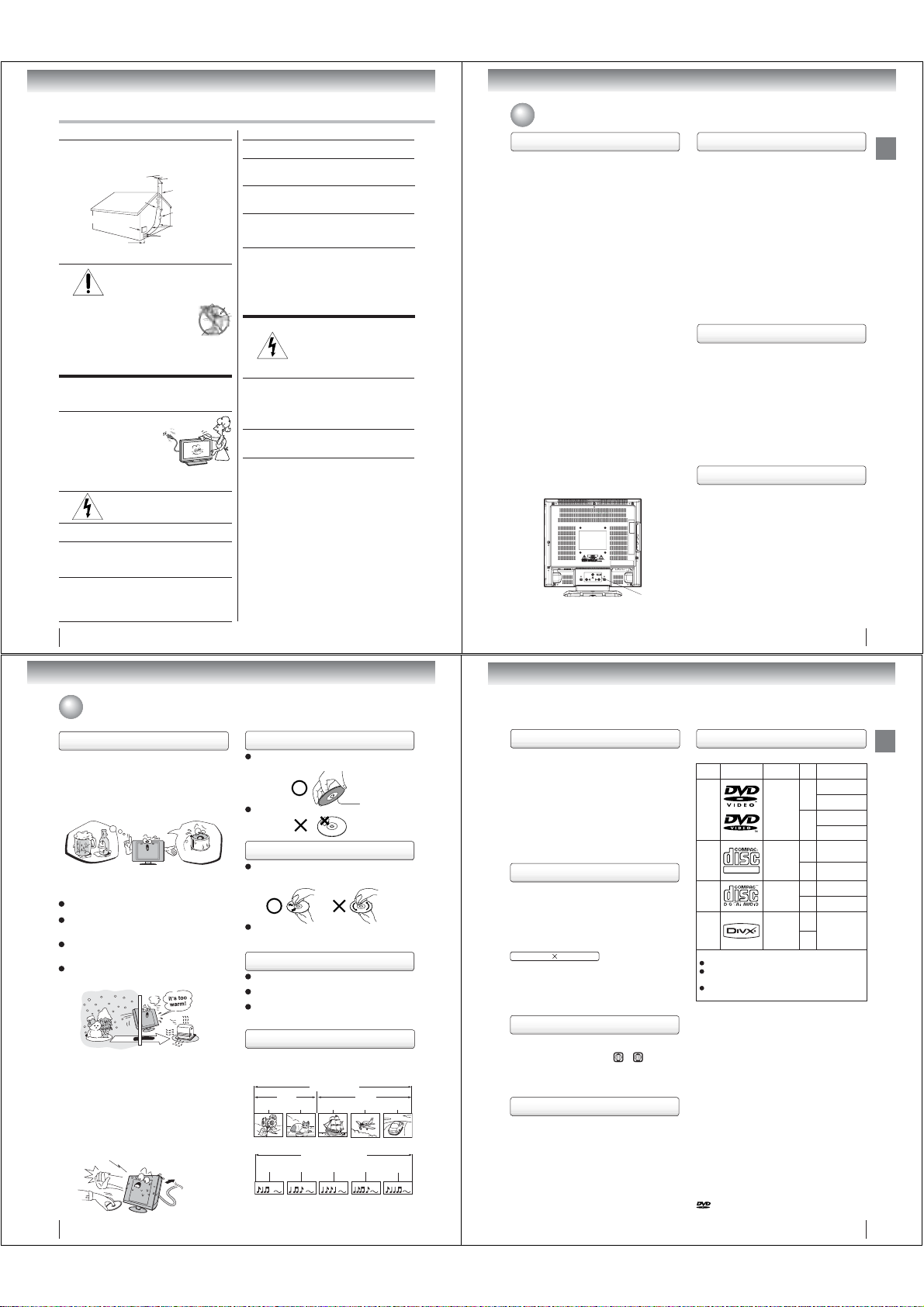
Structure of disc contents
Normally, DVD video discs are divided into titles, and
the titles are sub-divided into chapters. Video CDs and
Audio CDs are divided into tracks.
DVD video disc
Chapter 1 Chapter 2 Chapter 1 Chapter 2 Chapter 3
Video CD/Audio CD
Track 1 Track 2 Track 3 Track 4 Track 5
Each title, chapter or track is assigned a number, which
is called “title number”, “chapter number” or “track
number” respectively.
There may be discs that do not have these numbers.
DVD video disc
Title 1 Title 2
Video CD/Audio CD
Playback side
Notes on copyright
The unauthorized recording, use, distribution, or revision
of copyrighted materials including, without limitation,
television programs, videotapes, and DVDs, is prohibited
under the Copyright Laws of the United States and other
countries, and may subject you to civil and criminal liability.
This product incorporates copyright protection technology
that is protected by method claims of certain U.S. patents
and other intellectual property rights owned by Macrovision
Corporation and other rights owners. Use of this copyright
protection technology must be authorized by Macrovision
Corporation, and is intended for home and other limited
viewing uses only unless otherwise authorized by
Macrovision Corporation.
Reverse engineering or disassembly is prohibited.
About this owner’s manual
This owner’s manual explains the basic instructions of this
unit. Some DVD video discs are produced in a manner
that allows specifi c or limited operation during playback. As
such, the unit may not respond to all operating command.
This is not a defect in the unit. Refer to instruction notes of
discs.
The following symbol may appear on the TV screen during
operation.
It means that the operation is not permitted by the TV/DVD
or the disc.
For example, sometimes it is unable to stop the playback
of copyright message of the disc when the STOP ( )
button is pressed. Alternatively, this symbol may also
indicate that the feature is not available for the disc.
Notes on region numbers
The region number of this unit is 1. If region numbers,
which stand for their playable area, are printed on your
DVD video disc and you do not fi nd
playback will not be allowed by the player. (In this case,
the unit will display a message on-screen.)
Some DVDs that have no region code label may still be
subject to area restrictions and therefore not playable.
ALL
1
or
, disc
On Video CDs
This unit supports Video CDs equipped with the PBC
(Version 2.0) function. (PBC is the abbreviation of
Playback Control.) You can enjoy two playback variations
depending on types of discs.
•
Video CD not equipped with PBC function (Version 1.1)
Sound and movie can be played on this unit in the same
way as a DVD.
•
Video CD equipped with PBC function (Version 2.0)
In addition to operation of a Video CD not equipped with
the PBC function, you can enjoy playback of interactive
software with search function by using the menu
displayed on the TV screen (Menu Playback). Some of
the functions described in this owner’s manual may not
work with some discs.
Playable discs
This unit can play the following discs.
Disc Mark Contents
DVD
video
discs
Video
CDs
DIGITAL VIDEO
Audio
CDs
®
DivX
The following discs are also available.
DVD-R/RW discs of DVD video format
CD-R/CD-RW discs of CD-DA, Video CD, MP3, WMA,
®
JPEG or DivX
format
Kodak Picture CD and FUJICOLOR CD format
Some of these discs may be incompatible.
• You cannot play discs other than those listed above.
• You cannot play discs of DVD-RAM, DVD-ROM, CD ROM, Photo CD, etc., or non standardized discs even
if they may be labeled as above.
• Some CD-R/RWs cannot be played back depending
on the recording conditions.
• This unit uses the NTSC color system, and cannot
play DVD video discs recorded in any other color
system (PAL, SECAM, etc.).
• This unit can play an 8cm disc. Please do not use a
disc adapter. It may cause trouble.
• Please do not insert any disc of an irregular shape into
the unit, as it may interfere with the function of the unit.
You may not be able to remove it.
• Please do not use after market accessories, such as a
ring protector, as this may cause trouble with the
operation of the unit.
Because of problems and errors that can occur during the
creation of DVD and CD Software and/or the manufacture
of DVD and CD discs, Toshiba cannot assure that the
DVD player contained in this TV will successfully play
every disc bearing the DVD and CD logos.
If you happen to experience any diffi culty playing a DVD
and/or CD disc on the DVD player contained in this TV,
please contact Toshiba Customer Service.
is a trademark of DVD Format/Logo Licensing
Corporation.
Audio
Video
(moving
pictures)
Audio
Video
(moving
pictures)
Audio
Audio
Video
(moving
pictures)
Disc
Maximum
Size
playback time
Approx. 4 hours
(single sided disc)
12 cm
Approx. 8 hours
+
(double sided disc)
Approx. 80 minutes
(single sided disc)
8 cm
Approx. 160 minutes
(double sided disc)
Approx. 74 minutes
12 cm
+
(single sided disc)
Approx. 20 minutes
8 cm
(single sided disc)
Approx. 74 minutes
12 cm
(single sided disc)
Approx. 20 minutes
8 cm
(single sided disc)
12 cm
+
It depends on DivX®
quality
8 cm
7
Introduction
Page 5
Introduction
Contents
Introduction
SAFETY INSTRUCTIONS ................................ 3
Precautions....................................................... 5
Notes on discs .................................................. 6
Contents ........................................................... 8
Identifi cation of controls .................................... 9
Connections
Antenna connections ...................................... 13
Cable TV connections .................................... 14
Connecting to optional equipment .................. 15
Power source.................................................. 18
Basic setup
Starting setup ................................................. 19
Setting the language....................................... 20
To memorize channels....................................21
TV operation
TV operation ................................................... 22
Programming your favorite channels .............. 24
Setting the closed captions (analog caption/
caption) ................................................. 25
digital
Setting the CC advanced................................ 26
Setting the V-Chip........................................... 27
Viewing the wide-screen picture formats ........ 30
Selecting the cinema mode ............................32
Picture control adjustment .............................. 33
Adjusting the picture mode ............................. 33
Using the CableClear
Selecting the color temperature...................... 34
Sound control adjustment ............................... 35
Stereo and Second Audio Program (SAP) .....35
Selecting the audio languages ....................... 36
Selecting the digital output ............................. 36
Checking the signal meter .............................. 37
Using the auto shut off feature ....................... 37
®
feature ........................ 34
Basic playback
Playing a disc .................................................38
Advanced playback
Zooming.......................................................... 41
Locating desired scene................................... 41
Marking desired scenes.................................. 42
Repeat playback ............................................. 43
A-B Repeat playback ...................................... 43
Program playback........................................... 44
Random playback ........................................... 44
Changing angles..............................................45
Title selection ...................................................45
DVD menu .......................................................45
Changing soundtrack language .......................46
Subtitles ...........................................................46
Disc status .......................................................47
To turn off the PBC ..........................................47
MP3/WMA/JPEG/DivX
and Audio CD operation ..................................48
Repeat, random and program playback
using fi le browser.............................................52
Function setup
Customizing the function settings ....................54
Temporary cancel the rating level
by DVD disc .....................................................60
Others
Language code list ..........................................61
Troubleshooting ...............................................62
Reception disturbances ...................................64
Specifi cations ..................................................65
Limited United States Warranty .......................66
®
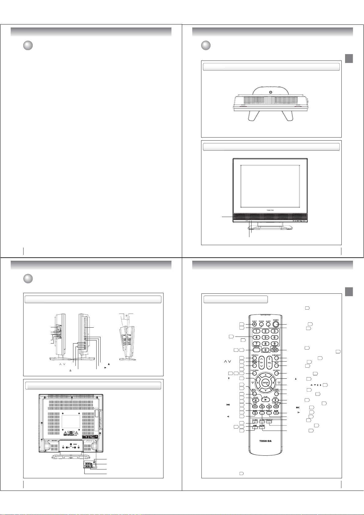
Identifi cation of controls
Top
Front
Speaker
Introduction
8
Introduction
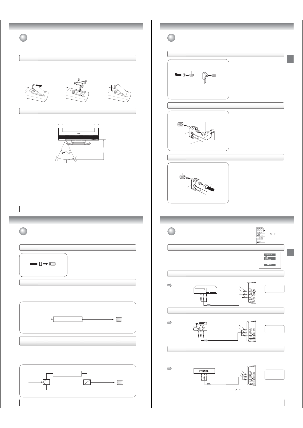
Identifi cation of controls (Continued)
Side
Left Side Right Side
S-VIDEO IN (LINE 1 IN) jack
AUDIO IN (L/R)
(LINE 1 IN) jacks
VIDEO IN (LINE 1 IN) jack
COAXIAL DIGITAL AUDIO
OUT jack
HEADPHONE jack
Rear
CHANNEL ( / ) buttons
VOLUME (+/-) buttons
POWER ( ) button
Disc slot
EJECT ( ) button
PLAY ( ) button
STOP ( ) button
Adjusting the angle of the base
Approx. 10°
Approx. 3°
You can adjust the
angle of the
TV-screen for 3°
forward or for 10°
backward from
vertical angle.
Hold the base of the
TV while adjusting
the angle.
Remote sensor
POWER indicator
Remote control
The instructions in this manual describe the function on the remote control. See the page in for details.
EJECT button
TV/DVD button
Direct channel selection
buttons (0
Numbered buttons (0
DISPLAY button
SUBTITLE button
CH / button
INPUT button
PLAY MODE button
ZOOM button
FAV ( ) button
MENU button
SETUP button
PLAY button
PAUSE button
CH RTN button
SKIP ( ) button
SLOW ( ) button
TOP MENU button
RETURN button
GAME button
-
9)
22
43
REV button
FF button
39
38
27
-
9)
23
47
46
22
15
41
47
44
24
20
54
38
39
23
40
40
40
40
45
49
54
23
POWER button
SLEEP button
JUMP button
Direct channel selection button (100/-)
AUDIO SELECT button
VOL +/- button
MUTE button
*DVD MENU button
FAV ( ) button
Direction buttons ( / / / )
ENTER button
EXIT/CANCEL button
STOP button
CLOSED CAPTION button
SKIP ( )button
SLOW ( ) button
MARKER button
ANGLE button
REPEAT A-B button
PIC SIZE button
19
23
41
22
23
45
24
20
39
40
40
42
45
43
30
9
Introduction
22
46
20
20
25
DC-LWB1
Antenna jack
VIDEO IN (LINE 2 IN) jack
ColorStream HD VIDEO IN (Y, PB, PR) jacks
AUDIO IN (L/R) (LINE 2 IN) jacks
10
*DVD MENU button
Use the DVD MENU button to
display the menu included on
many DVD video discs.
To operate a menu, follow the
instructions in “DVD menu.”
45
11
Page 6
Introduction
Connections
Identifi cation of controls (Continued)
Inserting batteries
Open the battery compartment
1
cover in the direction of the
arrow.
Install two “R03/AAA” batteries
23
(supplied), paying attention to
the polarity indicated in the
battery compartment.
Operation
• Aim the remote control at the remote sensor and press control buttons to operate.
•
Operate the remote control within 30° angle on either side of the remote sensor, up to a distance of approx. 5 meters.
Caution:
• Never throw batteries into a fi re.
Notes:
•
Be sure to use AAA size batteries.
• Dispose of batteries in a designated disposal area.
Batteries should always be disposed of with the environment in mind. Always dispose of batteries in accordance with
•
applicable laws and regulations.
• If the remote control does not operate correctly, or if the operating range becomes reduced, replace batteries with
new ones.
• When necessary to replace batteries in the remote control, always replace both batteries with new ones.
Never mix battery types or use new and used batteries in combination.
Always remove batteries from remote control if they are dead or if the remote control is not to be used for an extended
•
period of time. This will prevent battery acid from leaking into the battery compartment.
12
Replace the compartment
cover.
Approx. 5 meters
Antenna connections
If you are using an indoor or outdoor antenna, follow the instructions below that correspond to your antenna system.
If you are using a cable TV service (CABLE), see page 14 for Cable TV connections.
Combination VHF/UHF antenna (Single 75 ohm cable or 300 ohm twin-lead wire)
Antenna
jack
75 ohm coaxial cable
(not supplied)
Antenna
jack
300-75 ohm matching
transformer (not supplied)
Connect the 75 ohm cable from the combination
VHF/UHF antenna to the antenna jack on the back
of the TV/DVD.
If your combination VHF/UHF antenna has a 300
ohm twin-lead wire, use the 300-75 ohm matching
transformer (not supplied).
Combination VHF/UHF antenna (Separate VHF and UHF 300 ohm twin-lead wires)
Antenna
jack
Combiner
(not supplied)
UHF 300 ohm
twin-lead wire
(not supplied)
300-75 ohm matching
transformer (not supplied)
VHF 300 ohm
twin-lead wire
(not supplied)
Connect the UHF 300 ohm twin-lead wire to the
combiner (not supplied). Connect the VHF 300 ohm
twin-lead wire to the 300-75 ohm matching transformer
(not supplied). Attach the transformer to the combiner,
then attach the combiner to the antenna jack on the
back of the TV/DVD.
Separate VHF/UHF antennas (75 ohm VHF cable and 300 ohm UHF twin-lead wires)
Antenna
jack
Combiner
(not supplied)
UHF 300 ohm
twin-lead wire
(not supplied)
VHF 75 ohm
(not supplied)
Connect the VHF 75 ohm cable and UHF 300 ohm
twin-lead wire to the combiner (not supplied).
Attach the combiner to the antenna jack on the back
of the TV/DVD.
13
Connections
Connections
Cable TV connections
This TV/DVD has an extended tuning range and can tune most cable channels without using a Cable TV converter box.
Some cable companies offer “premium pay channels” in which the signal is scrambled. Descrambling these signals for
normal viewing requires the use of a descrambler device which is generally provided by the cable company.
For subscribers to basic cable TV service
For basic cable service not requiring a converter/descrambler
box, connect the Cable TV 75 ohm coaxial cable directly to the
Antenna jack on the back of the TV/DVD.
75 ohm
coaxial cable
Antenna
jack
For subscribers to scrambled cable TV service
If you subscribe to a cable TV service which requires the use of a converter/descrambler box, connect the
incoming 75 ohm coaxial cable to the converter/descrambler box. Using another 75 ohm coaxial cable, connect
the output jack of the converter/descrambler box to the antenna jack on the TV/DVD. Follow the connections
shown below. Set the TV/DVD to the output channel of the converter/descrambler box (usually channel 3 or 4)
and use the converter/descrambler box to select channels.
Incoming 75 ohm
Cable TV
For subscribers to unscrambled basic cable TV service with scrambled
premium channels
If you subscribe to a cable TV service in which basic channels are unscrambled and premium channels require
the use of a converter/descrambler box, you may wish to use a signal splitter and an A/B Switch box (available
from the cable company or an electronics supply store). Follow the connections shown below. With the switch in
the “B” position, you can directly tune any nonscrambled channels on your TV/DVD. With the switch in the “A”
position, tune your TV/DVD to the output of the converter/descrambler box (usually channel 3 or 4) and use the
converter/descrambler box to tune scrambled channels.
Incoming
75 ohm
Cable TV
Splitter
Converter/
descrambler
Converter/
descrambler
A/B switch
75 ohm cable to
A
B
TV/DVD
75 ohm cable
to TV/DVD
Antenna
jack
Antenna
jack
14
Connecting to optional equipment
You can enjoy VCR, camcorder or TV game with connection to external input.
0-3
CH
INPUT
GAME
/
Using the audio/video inputs
Press INPUT to view a signal from another device connected to your TV, such as
a VCR or DVD player. You can select ANT, VIDEO1 (on the left side), VIDEO2 (on
the back panel) or ColorStream HD (on the back panel) depending on which input
jacks you used to connect your devices.
Press INPUT on the remote control to display the current signal source.
To change the input source, press INPUT again or press 0-3.
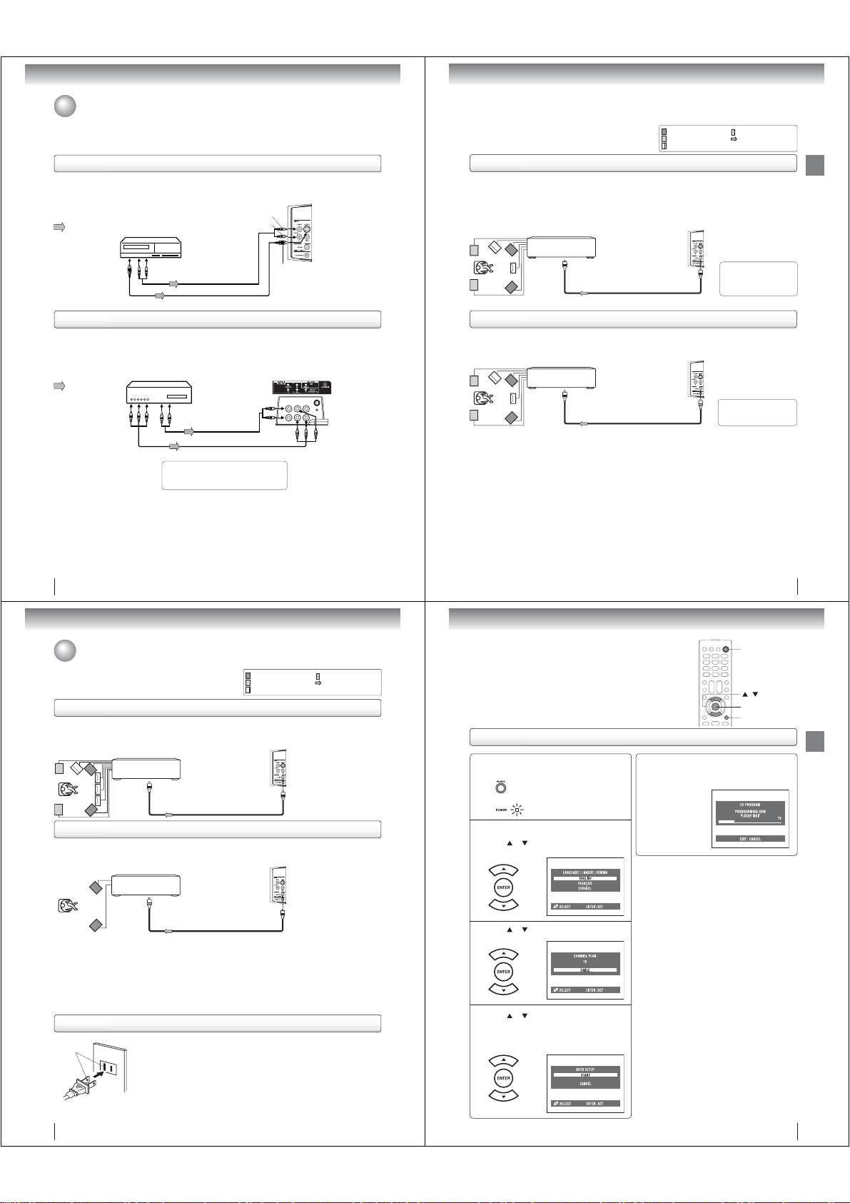
Connecting to a VCR
To playback from the VCR, connect the VCR to the TV/DVD as shown.
Select the “VIDEO1” by pressing INPUT repeatedly.
: Signal fl ow
VCR
To Audio/Video OUT
Audio/Video cable (not supplied)
(white)
(yellow)
(red)
Left side (LINE 1 IN)
To AUDIO(L/R)/VIDEO IN
The LINE 2 IN
terminals can be used
in the same way.
Connecting to a camcorder
To playback from the camcorder, connect the camcorder to the TV/DVD as shown.
Select the “VIDEO1” by pressing INPUT repeatedly.
: Signal fl ow
Camcorder
To Audio/Video OUT
Audio/Video cable (not supplied)
Left side (LINE 1 IN)
(white)
(red)
(yellow)
To AUDIO(L/R)/VIDEO IN
The LINE 2 IN
terminals can be used
in the same way.
Connecting to a TV Game
You can enjoy playing a TV game on the screen by adjusting to the suitable brightness for your eyes.
1. Connect a TV Game to the TV/DVD.
2. Select the “GAME” by pressing GAME.
The GAME mode screen appears.
• This TV/DVD has the GAME mode function (see page 23).
: Signal fl ow
To Audio/Video OUT
Audio/Video cable (not supplied)
Notes:
• You can also change the TV screen to the desired mode by pressing the CH
• The TV/DVD can also be used as a display device for many video games. However, due to the wide variety of different types of signal
generated by these devices and subsequent hook-up variations required, they have not all been included in the suggested connection
diagrams. You’ll need to consult each component’s Owner’s Manual for additional information.
• Interactive video games that involve shooting a “gun” type of joystick at on-screen target may not work on this TV/DVD.
(white)
(red)
(yellow)
/
buttons.
Left side (LINE 1 IN)
To AUDIO(L/R)/VIDEO IN
Only the LINE 1
IN terminals can
be used with the
GAME mode.
15
Connections
Page 7
Connections
Connecting to optional equipment (Continued)
Connecting to an optional equipment with S-video output
If you connect a VCR with an S-VIDEO cable to the S-VIDEO IN jack on the left side of the TV/DVD, you must
also connect the audio cables to the AUDIO IN (LINE 1 IN) jacks on the left side of the TV/DVD. The S-VIDEO
cable only carries the video signal. The audio signal is separated.
Select the “VIDEO1” by pressing INPUT repeatedly.
: Signal fl ow
Ex. VCR with S-Video
To AUDIO (L/R) IN
(playback)
To S-VIDEO OUT
Note: When the S-VIDEO cable and the standard video cable are connected at the same time, the S-video cable takes precedence.
To Audio (L/R) OUT
Audio cable (not supplied)
S-Video cable (not supplied)
Connecting an optional equipment with ColorStream® (Component video) output
Your TV/DVD is capable of using ColorStream® (component video). Connecting your TV/DVD to a component
video compatible DVD player, such as a Toshiba DVD player with ColorStream
quality and performance.
Select the “ColorStream HD” by pressing INPUT repeatedly.
Ex. DVD player with Component video
: Signal fl ow
To Component
Video OUT
Notes:
• The ColorStream
480p, 720p progressive signals.
• Refer to the owner’s manual of the connected equipment as well.
• When you connect the unit to other equipment, be sure to turn off the power and unplug all of the equipment
from the wall outlet before making any connections.
• If you place the unit near a tuner or radio, the radio broadcast sound might be distorted. In this case, place the
unit away from the tuner and radio.
®
inputs on this unit are for use with devices that output 480i, 1080i interlaced signals and
To Audio (L/R) OUT
When using the Component video cable,
an Audio cable must be connected to
AUDIO IN (L/R) (LINE 2 IN) jacks.
To AUDIO (L/R) IN
Audio cable (not supplied)
Component video cable (not supplied)
Left side (LINE 1 IN)
(white)
(red)
To S-VIDEO IN
®
can greatly enhance picture
Rear lower right of the TV
To ColorStream HD
) IN
(Y, P
B, PR
You can enjoy high quality dynamic sounds by connecting the
TV/DVD to optional audio equipment.
This section uses the following reference mark.
*
: Front speaker
: Rear speaker
: Sub woofer
: Center speaker
: Signal fl ow
Connecting to an amplifi er equipped with a Dolby® Digital decoder
Dolby Digital
Dolby Digital is the surround sound technology used in theaters showing the latest movies, and is now available to reproduce
this realistic effect in the home. You can enjoy motion picture and live concert DVD video discs encoded via the Dolby Digital
recording system with this dynamic realistic sound by connecting the TV/DVD to a 6 channel amplifi er equipped with a Dolby
Digital decoder or Dolby Digital processor. If you have a Dolby Surround Pro Logic decoder, you will obtain the full benefi t of
Pro Logic from the same DVD movies that provide full 5.1-channel Dolby Digital soundtracks, as well as from titles with the
Dolby Surround mark.
Amplifi er equipped with a
Dolby Digital decoder
To COAXIAL
type digital
audio input
75 : coaxial cable (not supplied)
Left side (LINE 1 IN)
To COAXIAL DIGITAL
AUDIO OUT
Manufactured under license
from Dolby Laboratories.
Dolby and the double-D symbol
are trademarks of Dolby
Laboratories.
Connecting to an amplifi er equipped with a DTS® decoder
Digital Theater Systems (DTS)
DTS is a high quality surround technology used in theaters and now available for home use, on DVD video discs or audio CDs.
If you have a DTS decoder or processor, you can obtain the full benefi t of 5.1 channel DTS encoded sound tracks on DVD
video discs or audio CDs.
Amplifi er equipped with
a DTS decoder
To COAXIAL
type digital
audio input
75 : coaxial cable (not supplied)
Left side (LINE 1 IN)
To COAXIAL DIGITAL
AUDIO OUT
“DTS” and “DTS Digital Out”
are registered trademarks of
DTS, Inc.
Connections
16
Connections
Connections
Connecting to optional equipment (Continued)/Power source
This section uses the following reference mark.
*
: Front speaker
: Rear speaker
: Sub woofer
: Center speaker
: Signal fl ow
Connecting to an amplifi er equipped with an MPEG audio decoder
MPEG2 sound
You can enjoy motion picture and live concert DVD video discs encoded via the MPEG2 recording system with dynamic
realistic sound by connecting an amplifi er equipped with an MPEG2 audio decoder or MPEG2 audio processor.
Amplifi er equipped with an
MPEG2 audio decoder
To COAXIAL
type digital
audio input
75 : coaxial cable (not supplied)
Left side (LINE 1 IN)
To COAXIAL DIGITAL
AUDIO OUT
Connecting to an amplifi er equipped with a digital audio input
2 channel digital stereo
You can enjoy the dynamic sound of 2 channel digital stereo by connecting an amplifi er equipped with a digital audio input and
speaker system (right and left front speakers).
Note: PCM audio is limited to DVD or CD playback.
Amplifi er equipped with a
Digital audio input
To COAXIAL
type digital
audio input
Notes:
• DO NOT connect the COAXIAL DIGITAL AUDIO OUT jack of the TV/DVD to the AC-3 RF input of a Dolby Digital Receiver.
This input on your A/V Receiver is reserved for Laserdisc use only and is incompatible with the COAXIAL DIGITAL AUDIO
OUT jack of the TV/DVD.
• Connect the COAXIAL DIGITAL AUDIO OUT jack of the TV/DVD to the “COAXIAL” input of a Receiver or Processor.
• Refer to the owner’s manual of the connected equipment as well.
• When you connect the TV/DVD to other equipment, be sure to turn off the power and unplug all of the equipment from the
wall outlet before making any connections.
•
The output sound of the TV/DVD has a wide dynamic range. Be sure to adjust the receiver’s volume to a moderate listening level.
Otherwise, the speakers and your hearing may be damaged by a sudden high volume sound.
• Turn off the amplifi er before you connect or disconnect the TV/DVD’s power cord. If you leave the amplifi er ’s power on, the
speakers may be damaged.
75 : coaxial cable (not supplied)
Left side (LINE 1 IN)
To COAXIAL DIGITAL
AUDIO OUT
Power source
Wider Hole
and Blade
Polarized AC Cord Plug
(One blade is wider than the other.)
18
AC Outlet
TO USE AC POWER SOURCE
Use the AC polarized line cord provided for operation on AC. Insert the AC cord plug
into a standard 120V 60Hz polarized AC outlet.
Notes:
• Never connect the AC line cord plug to other than the specifi ed voltage (120V 60Hz).
Use the attached power cord only.
• If the polarized AC cord does not fi t into a non-polarized AC outlet, do not attempt to
fi le or cut the blade. It is the user’s responsibility to have an electrician replace the
obsolete outlet.
•
If you cause a static discharge when touching the unit and the unit fails to function, simply unplug
the unit from the AC outlet and plug it back in. The unit should return to normal operation.
• If the AC cord plug is plugged in for the fi rst time, wait for approx. 5 seconds before
pressing the POWER button.
Basic setup
Starting setup
The STARTING SETUP function helps to install your unit easily.
It leads you the Language selection, TV/CABLE selection and auto
channel memory automatically.
IMPORTANT: Make sure that the antenna or cable TV system
connection is made!
Starting setup
To turn on the TV/DVD, press POWER.
The Power indicator on the front of the main unit
1
will light.
The starting setup function begins and the
Language setup menu appears on the screen.
2
or to select your desired language,
Press
then press ENTER.
Press or to select “TV” or “CABLE”, then
press ENTER.
3
Press or to select “START”, then press
ENTER.
4
If you select “CANCEL” and press
ENTER, the STARTING SETUP
stops and changes to the TV screen.
POWER
/
ENTER
EXIT/CANCEL
Now the “CH PROGRAM” starts.
5
Notes:
• The starting setup function will work only when you
press POWER for the fi rst time.
• The process of “CH PROGRAM” may take 15 to 30
minutes to complete, depending on your regional cable
service.
• If you press EXIT/CANCEL in the process of “CH
PROGRAM”, starting setup function is canceled.
After the starting setup is completed,
the TV channel appears on the screen.
17
Basic setup
19
Page 8
Basic setup
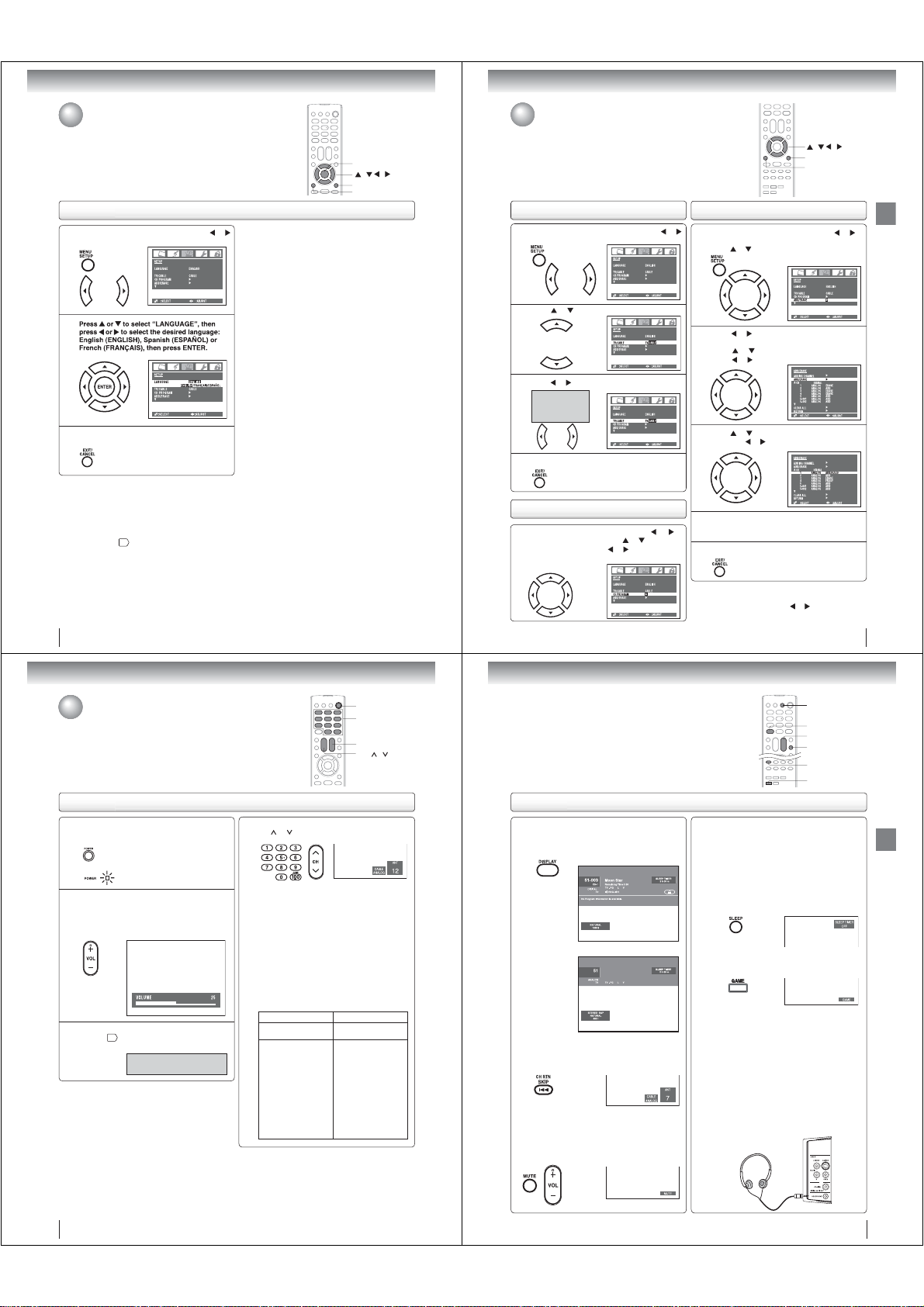
Setting the language
This TV/DVD can display the on screen language in English, Spanish or French
in the TV mode.
Select the language you prefer fi rst, then proceed with the other menu options.
Setting the language
Press MENU in the TV mode, then press or
to display the “SETUP” menu.
1
2
Press EXIT/CANCEL to clear the menu screen.
3
Notes:
• If the unit does not operate properly, or No key
operation (by the unit and/or the remote control):
Static electricity, etc., may affect the TV/DVD’s
operation. In such case, disconnect the AC cord once,
then connect it again.
• The TV section has its own menu and DVD section also
has its own menu
54
.
To memorize channels
This TV/DVD is equipped with a channel memory feature which allows
ENTER
/ / /
EXIT/CANCEL
MENU
channels to skip up or down to the next channel set into memory, skipping
over unwanted channels. Before selecting channels, they must be
programmed into the TV/DVD’s memory. To use this TV/DVD with an
antenna, set the TV/CABLE selection to the TV position. When shipped from
the factory, this selection is in the CABLE position.
TV/CABLE selection
Press MENU in the TV mode, then press or
to display the “SETUP” menu.
1
Press or to select “TV/CABLE”.
2
Press
or
TV - VHF/UHF
channels
CABLE - Cable
TV channels
to select “TV” or “CABLE”.
3
1
3
Press EXIT/CANCEL to clear the menu screen.
4
Automatic memory tuning
Press MENU in the TV mode, then press
display the “SETUP” menu. Press
“CH PROGRAM”, then press
The TV will begin memorizing all the channels available
in your area.
or
or
.
to select the
4
or
to
5
To add a digital channel you are watching:
Select a channel you want to add. Then select “ADDING
CHANNEL” in step 2, then press
/ / /
EXIT/CANCEL
MENU
To ADD/ERASE channels
Press MENU in the TV mode, then press
display the “SETUP” menu.
or
to select “ADD/ERASE”.
Press
Press or
.
The “ADD/ERASE” menu will appear.
2
Press or to select “ADD/ERASE”, then
press
or .
Press or to select the channel you want and
or to select “ADD” or “ERASE”.
then press
Repeat steps 3 for other channel you want to
add or erase.
Press EXIT/CANCEL to clear the menu screen.
or .
Basic setup
or
to
20
TV operation
TV operation
TV operation
To turn on the TV/DVD, press POWER.
The power indicator on the front of the main unit
1
will light.
Adjust the volume level by pressing VOL +/–.
The volume level will be indicated on the screen by
2
white bars. As the volume level increases, so do
the number of bars. If the volume decreases, the
number of white bars also decreases.
Set the TV/CABLE selection to the appropriate
21
position
3
22
.
TV - VHF/UHF channels
CABLE
- Cable TV channels
POWER
0–9,100/-
VOL +/CH /
Press direct channel selection (0–9, 100/-) or
CH
or
4
Notes:
• If a channel with no broadcast is selected, the sound will
automatically be muted.
• Digital channels may be represented by channel
numbers that include a “dash” (e.g., 85–002). These
digital channel numbers may not match the numbers in
the channel line-up provided by your cable company.
This is not a malfunction.
to select the channel.
TO SELECT ANALOG CHANNELS
When the TV/CABLE selection is in the CABLE
position, channels can be selected as follows:
TO SELECT CABLE TV CHANNELS:
1-9: Press 0 twice, then 1-9 as needed.
Example, to select channel 2, press 002.
10-99: Press 0, then the remaining 2 digits.
Example, to select channel 12, press 012.
100-125: Press the 3 digits in order. Example, to
select channel 120, press 120.
TO SELECT DIGITAL CHANNELS
Press the fi rst 3 digits, then press the “100/-”
button, followed by the remaining 3 digits.
Example, to select channel 015-001, press 015 -
001.
TV CATV
VHF
2-13
14-69
UHF
STD/HRC/IRC
14-36
(A) (W)
37-59
(AA) (WW)
60-85
(AAA) (ZZZ)
86-94
(86) (94)
95-99
(A-5) (A-1)
100-125
(100) (125)
21
SLEEP
DISPLAY
VOL +/-
MUTE
CH RTN
GAME
TV operation
■ DISPLAY
Press DISPLAY to display the information on the TV
screen.
To cancel the display, press DISPLAY again.
VHF
2-13
01
(5A)
■ CH RETURN
This button allows you to go back to the last channel
selected by pressing CH RTN. Press CH RTN again to
return to the last channel you were watching.
■ MUTE
Press MUTE to switch off the sound. The TV/DVD’s
sound will be silenced and “MUTE” will appear briefl y
on the screen. The sound can be switched back on by
pressing this button again or VOL +/–.
(Digital channel)
(Analog channel)
■ SLEEP
To set the TV/DVD to turn off after a preset amount of
time, press SLEEP on the remote control. The clock
will count up 10 minutes for each press of SLEEP
(OFF, 0h10m,... 1h50m, 2h00m). After the sleep
time is programmed, the display will appear briefl y
every ten minutes to remind you that the sleep timer
is operating. To confi rm the sleep timer setting, press
SLEEP and the remaining time will be displayed for a
few seconds. To cancel the sleep timer, press SLEEP
repeatedly until the display turns to OFF.
■ GAME MODE
After connecting a TV Game to the unit (see page 15),
press GAME. The TV screen changes to the Game mode.
• The Game mode screen is adjusted to the suitable
brightness for your eyes.
• If GAME is pressed during standby mode, the unit
turns on automatically and the Game mode screen
appears on the screen.
• Interactive video games that involve shooting a
“gun” type of joy-stick at an on-screen target may
not work on this TV/DVD.
■ HEADPHONES
Insert a stereo headphones (not supplied) with a 1/8” mini
plug into the HEADPHONE jack on the front panel.
If you connect headphones, the sound from TV speakers
is muted.
TV operation
23
Page 9
TV operation
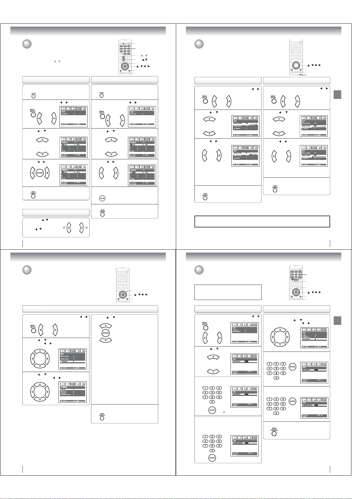
Programming your favorite channels
You can preset up to 12 of your favorite channels using the Favorite
Channel Programming feature. Because this feature scans through
only your favorite channels, it allows you to skip other channels you
do not normally watch.
You can still use CH
programmed in the TV’s memory or the Channel Numbers to directly
tune a channel.
To program your favorite channels
Press TV/DVD to select the TV mode, then select a
channel you want to program.
1
Press MENU, then press or to display the
“OPTION” menu.
2
Press
or
SET/CLEAR will be highlighted.
menu.
3
Press or to highlight “SET” and press ENTER.
4
Press EXIT/CANCEL to return to normal viewing.
5
Note:
Repeat steps 1-5 for up to 12 channels.
To select your favorite channels
Press the FAV / buttons on
the remote control to select your
favorite channels.
/ buttons will not
The FAV
work until you have programmed
you favorite channels.
/ to scan through all the channels you
to display the “FAVORITE CH”
To clear your favorite channels
1
2
3
4
5
6
Note:
Repeat steps 1-6 for the other channels.
24
TV/DVD
0–9, 100/-
CH /
FAV
ENTER
/ / /
EXIT/CANCEL
MENU
Press TV/DVD to select the TV mode, then select
a channel you want to clear.
Press MENU, then press or to display the
“OPTION” menu.
Press
or
to display the “FAVORITE CH”
SET/CLEAR will be highlighted.
menu.
Press or to highlight “CLEAR”.
Press ENTER until “0” replaces the channel
number you want to erase.
Press EXIT/CANCEL to return to normal viewing.
Setting the closed captions (analog caption/
digital caption)
WHAT IS CLOSED CAPTIONING?
This television has the capability to decode and display closed captioned
television programs. Closed captioning will display text on the screen for
hearing impaired viewers or it will translate and display text in another
language.
To set the analog caption
Press MENU in the TV mode, then press or
to display the “SETUP” menu.
1
Press
or to highlight “ANALOG CAPTION”.
2
Press
or to select the desired Closed
Caption mode.
3
• To view captions, select C1 or C2 (C1 displays
translation of the primary language in your area.)
Note: If the program or video you selected is not
closed captioned, no captions will display
on-screen.
• To view text, select T1 or T2.
Press EXIT/CANCEL to return to normal viewing.
4
Notes:
• You can also display the ANALOG CAPTION menu screen by pressing CLOSED CAPTION on the remote control.
• Digital caption feature is not available for analog channel.
Important Note:
If text is not available in your viewing area, a black rectangle may appear on-screen. If this happens, set
the Closed Caption feature to OFF.
To set the digital caption
Press MENU in the TV mode, then press or
to display the “SETUP” menu.
1
Press
or to highlight “DIGITAL CAPTION”.
2
Press
or to select the desired Closed
Caption mode.
3
You can choose from CS1, CS2, CS3, CS4, CS5,
CS6 and OFF.
Press EXIT/CANCEL to return to normal viewing.
4
/ / /
EXIT/CANCEL
MENU
CLOSED CAPTION
TV operation
25
TV operation
Setting the CC advanced
This feature is designed to customize digital captions only.
To set the CC advanced feature
Press MENU in the TV mode, then press or
to display the “SETUP” menu.
1
or to highlight “CC ADVANCED”,
Press
then press
2
3
or .
or to select the desired item to
Press
adjust, then press
or .
ENTER
/ / /
EXIT/CANCEL
MENU
Press or to select the desired setting, then
press ENTER.
4
You can select from among the following items and
parameters.
AUTO, SMALL, STANDARD, LARGE
TEXT SIZE:
TEXT TYPE: AUTO, DEFAULT, MONO W.
SERIF, PROP. W. SERIF, MONO
W/O SERIF, PROP. W/O SERIF,
CASUAL, CURSIVE, SMALL
CAPITALS
TEXT COLOR: AUTO, BLACK, WHITE, RED,
GREEN, BLUE, YELLOW,
MAGENTA, CYAN
TEXT EDGE: AUTO, NONE, RAISED,
DEPRESSED, UNIFORM,
LEFT DROP SHADOW, RIGHT
DROP SHADOW
BACKGROUND COLOR: AUTO, BLACK, WHITE,
RED, GREEN,
MAGENTA, CYAN
Press EXIT/CANCEL to return to normal
viewing.
5
Note:
It is impossible to select the same color with TEXT COLOR
and BACKGROUND COLOR.
BLUE, YELLOW,
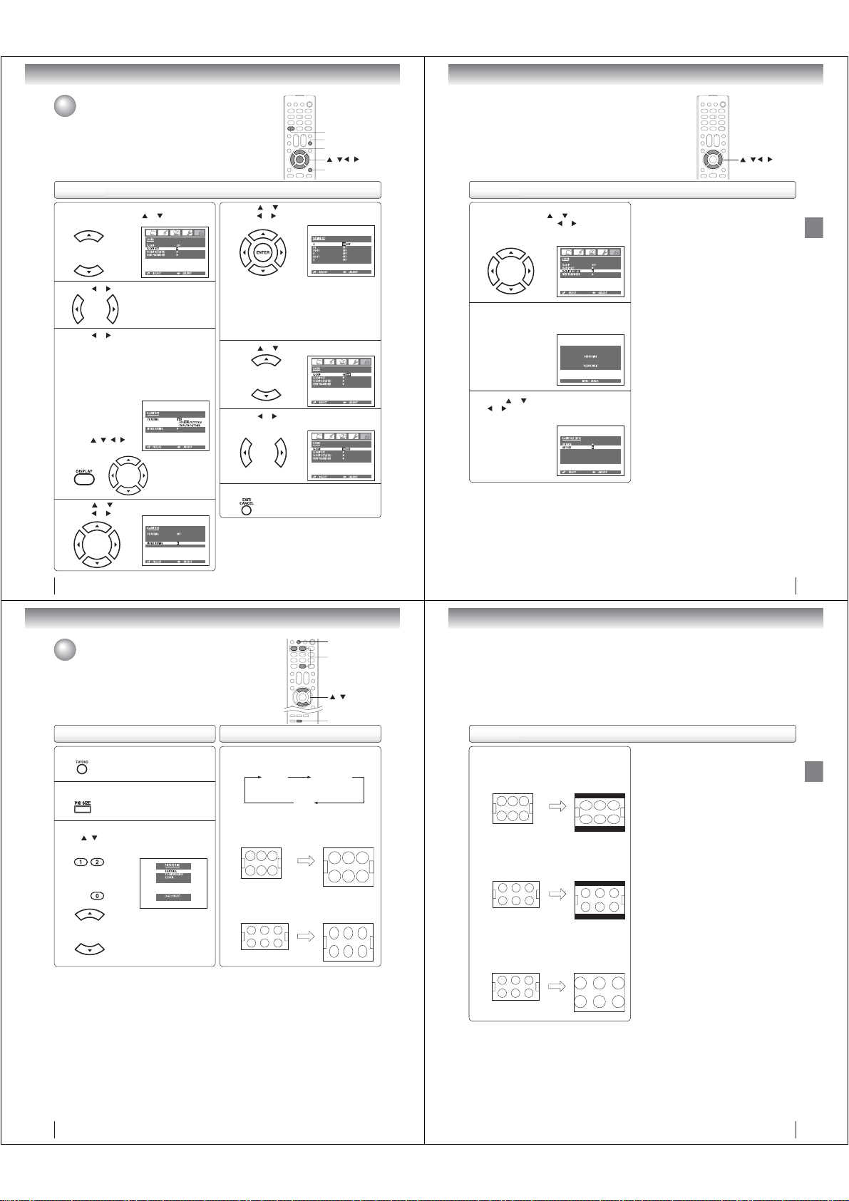
Setting the V-Chip
An age limitation can be set to forbid children to see and hear violent scenes or
pictures for adults, etc. The TV/DVD corresponds to “TV RATING” and “MOVIE
RATING”. To use the V-Chip function, you must register a password.
Notess:
If you forget the password, press DISPLAY four times within
fi ve seconds while the TV is in password entering mode. This
allows you to reset your password.
To register password To change password
Press MENU in the TV mode, then press or
to display the “LOCKS” menu.
1
Press or . New password entering screen
appears.
2
Enter the password (4 digits) using Number
buttons (0–9), then press ENTER.
3
“ ” appears instead of the number.
Enter the password (4 digits) using Number
buttons (0–9) again for the safety, then press
4
ENTER.
Now the password is registered and LOCKS setting
menu will appear on the display.
Repeat steps 1 ~ 3 in “To register password”
on left, then press
1
PASSWORD”, then press
Enter the new password using Number buttons
(0–9), then press ENTER.
2
Enter the same password again using Number
buttons (0–9) for safety, then press ENTER.
3
Press EXIT/CANCEL to clear the menu screen.
4
Note:
The V-Chip feature is available only for the U.S. V-Chip system.
The Canadian V-Chip system is not supported.
or to select “NEW
0–9
DISPLAY
ENTER
/ / /
EXIT/CANCEL
MENU
or .
TV operation
26
27
Page 10
TV operation
Setting the V-Chip (Continued)
To set the V-Chip
Repeat steps 1 ~ 3 in “To register password”
on page 27, then press
1
“V-CHIP SET”.
Press or to display “V-CHIP” menu.
2
Press or to select the desired rating.
3
OFF : TV RATING is not set
TV-Y : All children
TV-Y7 : 7 years old and above
TV-G : General audience
TV-PG : Parental guidance
TV-14 : 14 years old and above
TV-MA : 17 years old and above
When you select
TV- Y7, TV-PG, TV14 or TV-MA, press
DISPLAY to show
the contained rating.
/ / /
Press
to select the desired
item you want.
Press or to select “MOVIE RATING”, then
press
or .
4
28
or to highlight
DISPLAY
MUTE
ENTER
/ / /
EXIT/CANCEL
Press or to select
press
or
5
ENTER twice.
ON : MOVIE RATING is set
OFF : MOVIE RATING is not set
G : All ages
PG : Parental guidance
PG-13 : Parental guidance less than 13 years old
Under 17 years old Parental guidance suggested
R :
NC-17 : 17 years old and above
X : Adult only
Press or to select “V-CHIP”.
6
Press or to highlight “ON”.
Now your settings are set into the memory.
7
Press EXIT/CANCEL to clear the menu screen.
8
To use after the TV is protected
When you try to view a program with a ratings block, a message
will appear listing the program’s ratings. The program can still
be viewed if you press MUTE and then enter your password to
temporarily bypass the block.
Note:
The V-Chip function is activated only on programs that have
the rating signal.
the desired rating, then
to select “ON” or “OFF”. Press
As a supplement to the standard V-Chip rating system, your Toshiba Television
will be able to download an additional rating system, if such a system becomes
available in the future.
/ / /
To download the additional V-Chip rating system (when available)
Repeat steps 1~3 in “To register password” on
page 27, then press
1
SET (DTV)”, then press
(You cannot select this feature if the TV is not
receiving a digital signal for the current station.)
If the TV is not storing the additional rating
system, the TV will begin downloading it, which
2
may take some time to be completed.
Press
or , and
3
limits for the additional rating system.
or to higlight “V-CHIP
or .
or to select “RRT SET”, then press
set your preferred content rating
PLEASE NOTE THE FOLLOWING:
• You can only download the additional V-Chip rating
system when your TV is receiving a digital signal.
• When you download the additional rating system,
it may take some time for the download to occur.
• The V-Chip rating information and system are
not determined or controlled by the TV or Toshiba.
• The standard V-Chip rating system is available
whether your TV is receiving a digital signal or not,
and will block both analog and digital programs.
To set program blocking using the standard V-Chip
rating system, select V-CHIP SET in step 1 above
(see page 28 for details).
The downloadable V-Chip rating system is an
evolving technology, and availability, content, and
format may vary.
TV operation
29
TV operation
Viewing the wide-screen picture formats
You can view programs in a variety of picture sizes—NATURAL (4:3),
COMPRESSION (16:9), ZOOM. The way the image displays in any of the
picture sizes will vary depending on the format of the program you are viewing.
Select the picture size that displays the current program the way that looks
best to you.
To select the picture size
Press TV/DVD to select the TV mode.
1
Press PIC SIZE on the remote control.
2
Press the corresponding number button (0-2)
/ button to select the desired picture
or
3
size, as described on the right and on page 31.
About the picture size
Press PIC SIZE repeatedly on the remote control
to cycle among the three picture sizes, as
described below.
NATURAL (4:3) picture size
•
If receiving a 4:3 format (analog or digital) program,
select
image
• If receiving a 16:9 format (analog or digital)
program, select NATURAL PIC SIZE will typically
display the image stretched taller (squeezed.)
NATURAL COMPRESSION
ZOOM
NATURAL
PIC SIZE will typically display the
in its original
formatted proportion.
TV/DVD
0-2
/
PIC SIZE
About the picture size
COMPRESSION (16:9) picture size
• If receiving a 4:3 format (analog or digital)
select COMPRESSION PIC SIZE will
program,
display the image stretched wider with
typically
bars at the top and bottom.
• If receiving a 16:9 format (analog or digital)
program, select
typically display the image in its original
formatted proportion with bars at the top and
bottom.
ZOOM picture size (for 16:9 format programs)
• If receiving a 16:9 format (analog or digital)
program, select ZOOM PIC SIZE will typically
enlarge the image, retaining the original formatted
proportion, but with the sides edges hidden.
COMPRESSION
PIC SIZE will
TV operation
30
31
Page 11
TV operation
Selecting the cinema mode
When you view a DVD movie (3:2 pulldown processed) smoother
and more natural motion can be obtained by setting the CINEMA
MODE to FILM.
If you view a DVD movie from a DVD player connected to the
ColorStream (component video) inputs on the TV/DVD, the
CINEMA MODE feature may not work. This is not a malfunction.
To set the CINEMA MODE
Press MENU in the TV mode, then press or to
display the “SETUP” menu.
1
Press or to highlight “CINEMA MODE”.
2
Press or to select “FILM” or “VIDEO”.
3
Press EXIT/CANCEL to return to normal
viewing.
4
32
/ / /
EXIT/CANCEL
MENU
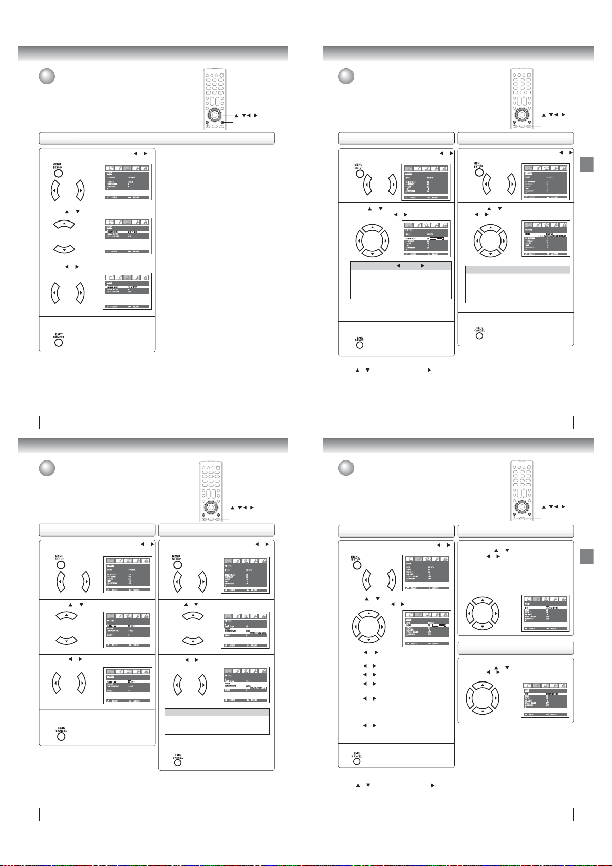
Picture control adjustment/
Adjusting the picture mode
Picture controls are factory preset but you can adjust them individually as follows:
And also you can select four picture modes— Sports, Standard, Movie, and
Memory—as described in the following table:
Picture control adjustment To adjust the picture mode
Press MENU in the TV mode, then press
to display the “PICTURE” menu.
1
Press or to select the item you want to
adjust, then press
2
Selection Pressing
BRIGHTNESS
CONTRAST
COLOR
TINT
SHARPNESS
Note:
The CONTRAST default setting is set to maximum
(+50) at the factory.
Press EXIT/CANCEL to clear the menu screen.
3
To return your picture adjustments to the factory preset levels
Press or to select “RESET”, then press .
The RESET function returns your picture quality adjustments
to the following factory settings:
Mode .......................... sports
Brightness .......... center (25)
Contrast ................ max (50)
Color .................. center (25)
or to adjust the setting.
darker
lower
paler
reddish
softer
Tint ....................... center (0)
Sharpness .......... center (25)
Color temperature ........ cool
lighter
higher
deeper
greenish
sharper
or
Press MENU in the TV mode, then press
to display the “PICTURE” menu.
1
Press or to select “MODE”, then press
or to select the desired picture mode.
2
Mode Picture quality
SPORTS
Bright and dynamic picture (factory-set)
STANDARD
Standard picture quality (factory-set)
MOVIE
Movie-like picture setting (factory-set)
MEMORY
Your personal preferences (set by you;
see “Picture control adjustment” as left)
Press EXIT/CANCEL to clear the menu screen.
3
Note:
You cannot select “MODE” in the Game mode.
/ / /
EXIT/CANCEL
MENU
or
33
TV operation
TV operation
Using the CableClear® feature/
Selecting the color temperature
To use the CableClear® feature To use the color temperature
1
2
3
4
®
CableClear
reduces visible interference in your TV picture. This is
useful when receiving a broadcast with a weak signal (especially
a Cable channel) or playing a video cassette or disc damaged by
repeated use.
Change the picture quality by selecting from three preset color
temperatures—cool, medium or warm.
Press MENU in the TV mode, then press or
to display the “PICTURE” menu.
Press or to highlight “Cable Clear”.
Press or to highlight “ON” or “OFF”.
Press EXIT/CANCEL to return to normal
viewing.
1
2
3
Mode Picture quality
COOL
MEDIUM
WARM
4
/ / /
EXIT/CANCEL
MENU
Press MENU in the TV mode, then press or
to display the “PICTURE” menu.
Press
or
to select “COLOR TEMPERATURE”.
Press or to select the desired color mode.
Bluish
Neutral
Reddish
Press EXIT/CANCEL to clear the menu screen.
Sound control adjustment/
Stereo and Second Audio Program (SAP)
Sound controls are factory preset but you can adjust them individually as follows:
The TV/DVD is equipped with a feature known as multi-channel TV sound or MTS.
MTS broadcasts greatly enhance TV viewing by bringing you programs with high
fi delity stereo sound.
MTS also provides an extra channel called the Second Audio Program or SAP
which broadcasters can use to transmit a second language for bilingual
transmission or for other purposes.
Sound control adjustment
Press MENU in the TV mode, then press or
to display the “AUDIO” menu.
1
Press or to select the item you want to
adjust, then press
2
MTS
Press
“MONO”.
BASS:
Press
TREBLE:
Press
BALANCE:
Press
both speakers.
STABLE SOUND:
Press
ON:
volume level to prevent extreme changes in
volume when the signal source is changed.
OFF: Normal sound.
SURROUND:
Press
ON:
OFF: Normal sound.
Press EXIT/CANCEL to clear the menu screen.
3
or to adjust the setting.
or to select “STR” (STEREO), “SAP” or
or to adjust the bass sound.
or to adjust the treble sound.
or to obtain an equal sound level from
or to select “ON” or “OFF”.
The StableSound® feature limits the highest
or to select “ON” or “OFF”.
The dynamic presence and sound created offers
a thoroughly enjoyable listening experience.
Listening to stereo sound
Repeat step 1 in “Sound control adjustment” on
left, then press
Then press
You can enjoy stereo sound from the left and right
speakers.
• If the broadcast signal is not strong enough or clear
stereo sound is not available, select “MONO”. The
noise should be eliminated.
Listening to SAP (Second Audio Program)
Repeat step 1 in “Sound control adjustment” on
left, then press
Then press
or to select “MTS”.
or to select “STR”.
or to select “MTS”.
or to select “SAP”.
/ / /
EXIT/CANCEL
MENU
TV operation
Note:
You cannot select “COLOR TEMPERATURE” in the Game
mode.
34
To return BASS/TREBLE/BALANCE control
adjustments to the factory preset levels
Press
or to select “RESET”, then press .
The RESET function returns your audio adjustments to
the following factory settings:
Bass ................. center (25)
Balance .............. center (0)
Treble ............... center (25)
35
Page 12
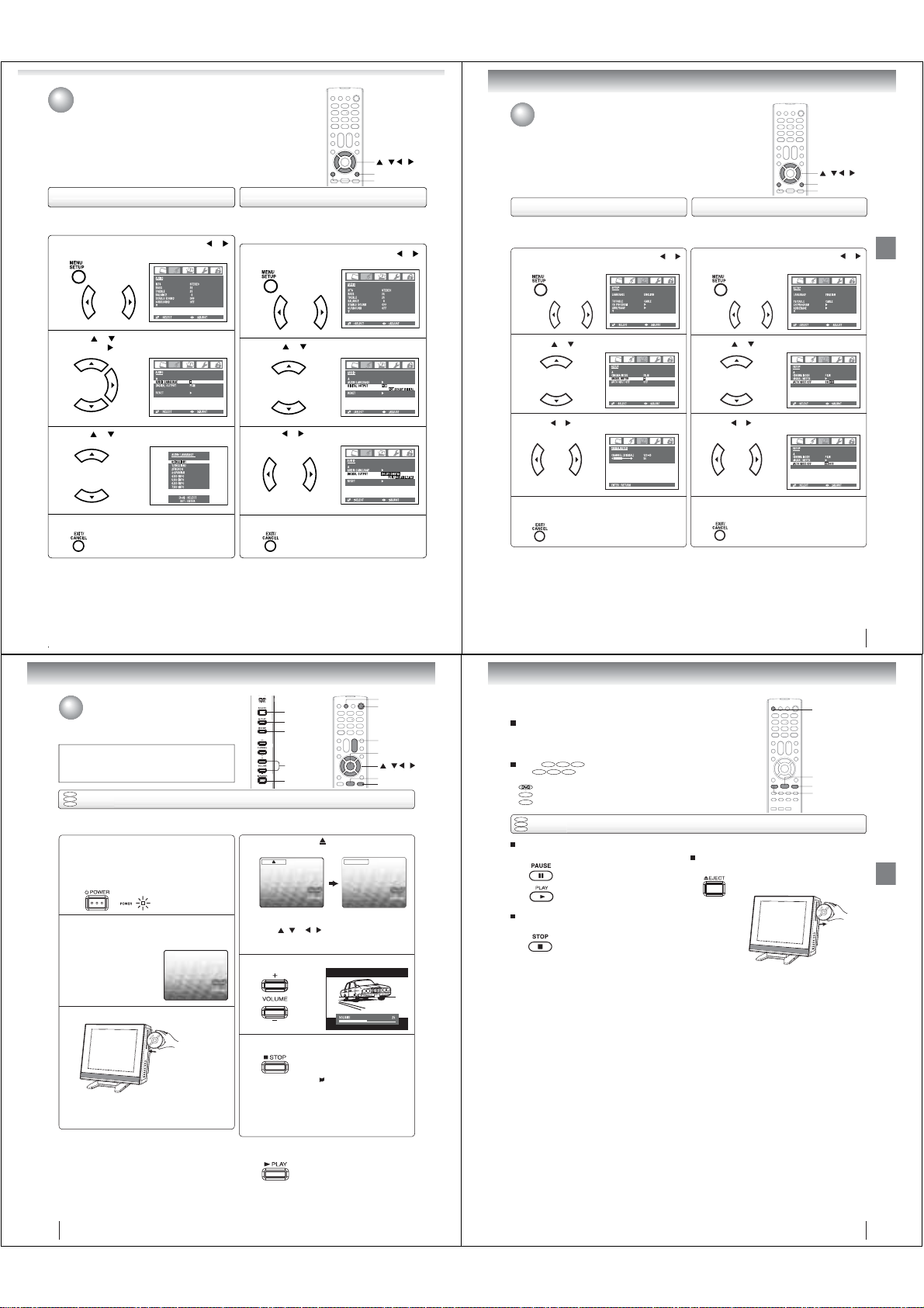
Selecting the audio languages/
Selecting the digital output
Checking the signal meter/
Using the auto shut off feature
signal, you can select one of the audio language.
Press MENU in the TV mode, then press or
to display the “AUDIO” menu.
1
Press or to select “AUDIO LANGUAGE”,
then press
2
3
4
Note:
Audio language feature is not available for analog channel.
.
Press
or
to select your desired language.
Press EXIT/CANCEL to clear the menu screen.
/ / /
EXIT/CANCEL
MENU
To select the digital outputTo select the audio languages
you connect a Dolby Digital decoder or other digital audio
system to the coaxial digital audio output on the TV.
Press MENU in the TV mode, then press or
to display the “AUDIO” menu.
1
Press or to select “DIGITAL OUTPUT”.
2
Press
or
to select “PCM” or “DOLBY
DIGITAL”.
3
Press
EXIT/CANCEL
4
Notes:
• Digital output feature is available for only digital channel.
• Digital audio output is effective for only digital source (digital
channel or DVD playback).
to clear the menu screen.
You can check the strength of the digital signal by viewing the
digital signal meter.
Press MENU in the TV mode, then press or
to display the “SETUP” menu.
1
Press or to highlight “SIGNAL METER”.
2
Press or to check the digital signal strength.
3
Press
EXIT/CANCEL
screen.
4
Notes:
• Signal meter feature is not available for analog channels.
• After approximately 4 minutes, SIGNAL METER screen will
return to normal TV-opreation automatically.
• When you select a vacant channel, the signal meter may react.
to return to the normal
/ / /
EXIT/CANCEL
MENU
To use the auto shut off featureTo check the signal meter
In case of “AUTO SHUT OFF” is “ON”, if a station being
viewed stops broadcasting, the TV will automatically shut itself
off after 15 minutes.
Press MENU in the TV mode, then press or
to display the “SETUP” menu.
1
Press or to highlight “AUTO SHUT OFF”.
2
Press or to highlight “ON”.
3
Press
EXIT/CANCEL
screen.
4
to return to the normal
TV operation
Basic playback
Playing a disc
This section shows you the basics on how to play a disc.
CAUTION
Keep your fi ngers well clear of the disc slot when disc is
loading or unloading. Neglecting to do so may cause serious
personal injury.
DVD
VCD
Basic playback
CD
Preparations:
• When connecting to other equipment, turn the power off.
Press POWER on the unit or on the remote control
to turn on the unit.
1
The Power indicator on the front of the main unit will light.
• Every time you press POWER, the TV/DVD starts
from TV mode.
• When using an amplifi er, switch on the amplifi er.
Press TV/DVD on the remote control to select DVD
mode.
2
The DVD startup screen will appear on the TV screen.
Load a disc in the disc slot.
3
Load the disc in the disc slot with the label side facing
forward. (If the disc has a label.) Hold the disc without
touching either of its surfaces, align it with the guides,
and place it in position.
EJECT
PLAY
STOP
VOLUME +/–
POWER
On the TV screen, “ ” changes to “Reading” and
then playback commences.
4
A menu screen will appear on the TV screen if the
disc has a menu feature.
/ or / on the remote control to
Press
select title, then press ENTER. Title is selected and
play commences.
Press VOLUME + or – to adjust the volume.
5
Press STOP to end playback.
6
To start playback in the stop mode
Press PLAY.
Reading
Resuming facility
• The unit records the stopped
point, depending on the disc.
” appears on the screen.
“
Press PLAY to resume playback
(from the scene point).
• If you press STOP again
(“ ” appears on the TV screen.),
the unit will clear the stopped
point.
TV/DVD
POWER
VOL
ENTER
/
PLAY
STOP
+/–
/ /
To obtain a higher quality picture
Occasionally, some picture noise may appear on the TV screen while playing a
DVD video disc because the high resolution pictures on these discs include a lot
of information. In such case, you may reduce the SHARPNESS with the Picture
control adjustment menu (see page 33).
DVD
VCD CD
About
DVD
The
function described under that heading.
: You can use this function with DVD video discs.
VCD
: You can use this function with Video CDs.
CD
: You can use this function with Audio CDs and CD-R/RW CDs.
DVD
VCD
Basic playback
CD
To pause playback (still mode)
Press PAUS E during playback.
To stop playback
Press STOP.
Notes:
•
If a non-compatible disc is loaded, “Incorrect Disc”, “Region Code Error” or “Parental Error” will appear on the TV screen
according to the type of loaded disc. In this case, check your disc again (see pages 7 and 58).
•
Some discs may take a minute or so to start playback.
•
When you set a single-faced disc label downwards (ie. the wrong way up), “Reading” will appear on the display for a few
minutes and then “Incorrect Disc” will continue to be displayed.
•
Some discs may not work the resuming facility.
•
Resuming cannot function when you play a PBC-featured Video CD while the PBC is on. To turn off the PBC, see page 47.
•
Some playback operations of DVDs may be intentionally fi xed by software producers. Since this unit plays DVDs according
to the disc contents the software producers designed, some playback features may not be available. Also refer to the
instructions supplied with the DVDs.
•
Do not move the unit during playback. Doing so may damage the disc.
•
Use the EJECT button to unload and eject the disc.
•
Do not put any objects other than discs on the disc slot. Doing so may cause the unit to malfunctions.
•
There may be a slight delay between the button is pressed and the function activates.
VCD CD
icons on the heading bar show the playable discs for the
To resume normal playback,
press PLAY.
• The sound is muted during still
mode.
To remove the disc
Press EJECT.
Remove the disc after the disc comes
out.
EJECT
PLAY
STOP
PAUSE
37
Basic playback
Note:
If the unit does not operate properly:
Static electricity, etc., may affect the TV/DVD’s operation. In such
case, disconnect the AC cord, then connect it again.
38
39
Page 13
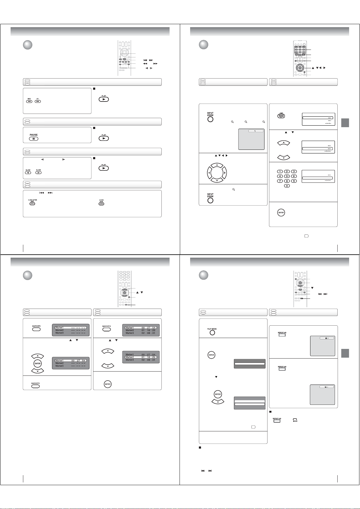
Basic playback
Advanced playback
Playing a disc (Continued)
PAUSE
PLAY
SKIP /
REV / FF
SLOW /
DVD
VCD
Playing in fast reverse or fast forward directions
CD
Press REV or FF during playback.
REV: Fast reverse playback
FF: Fast forward playback
Each time you press REV or FF
button, the playback speed changes.
DVD
Playing frame by frame
VCD
Press PAUSE during still playback.
DVD
VCD
Press SLOW (REVERSE) or (FORWARD)
during playback.
DVD
VCD
CD
Press SKIP or repeatedly to display the chapter or track number you want.
Playback starts from the selected chapter or track.
Note:
A “Prohibition” symbol “ ” may appear at the upper right of the screen. This symbol means either the feature you tried is not
available on the disc, or the TV/DVD cannot access the feature at this time. This does not indicate a problem with the TV/DVD.
Each time you press PAUSE, the
picture advances one frame.
Playing in slow-motion
Each time you press the button, the
slow-motion speed changes.
Locating a chapter or track
To locate succeeding chapters or tracks.
To resume normal playback
Press PLAY.
Notes:
• The TV/DVD mutes sound during reverse and forward scan
of DVD and Video CD discs. However, the TV/DVD plays
sound during fast forward or fast reverse play of audio CDs.
• The playback speed may differ depending on the disc.
To resume normal playback
Press PLAY.
Note:
The sound is muted during frame by frame playback.
To resume normal playback
Press PLAY.
Notes:
• The sound is muted during slow-motion playback.
• The Video CD cannot play Reverse Slow.
Playback starts from the beginning of
the current chapter or track.
When you press twice in quick successions,
playback starts from the beginning of
the preceding chapter or track.
Zooming/Locating desired scene
DVD
VCD
Zooming
CD
This unit will allow you to zoom in on the frame image.
You can then make selections by switching the position
of the frame.
Press ZOOM during playback.
1
2
3
Notes:
• You can select the Pause, Slow or Search playback in the
zoom mode.
• Some discs may not respond to zoom feature.
The center part of the image will be
zoomed in.
Each press of ZOOM will change the
ZOOM
1 (x 1.3), 2 (x 1.5) and
3 (x 2.0).
Press
/ / /
frame.
In the zoom mode, press ZOOM repeatedly to
return to a 1:1 view ( Off).
to view a different part of the
You may move the frame from
the center position to UP, DOWN,
LEFT or RIGHT direction.
1
0–9
JUMP
DISPLAY
ZOOM
/ / /
ENTER
DVD
VCD
Locating desired scene
CD
Use the title, chapter and time recorded on the DVD disc to
locate the desired point to playback. In the case of VCD/Audio
CD discs, time and track are used to locate the desired point
to playback.
To check the title, chapter/track and time, press DISPLAY.
Press JUMP during playback or resume stop mode.
1
Press or to select the “Time”, “Title/Track”
or “Chapter”.
2
Press Number buttons (0–9) to input the number.
3
• If you input a wrong number, press
EXIT/CANCEL.
• Refer to the package supplied with
the disc to check the numbers.
Press ENTER. Playback starts.
4
Note:
In case of the Video-CD playback with PBC, the JUMP does not
work. To turn off PBC, see page
• When you change the title,
playback starts from Chapter 1 of
the selected title.
• Some discs may not work in the
above operation.
EXIT/CANCEL
Jump
Title
Chapter
Time
Jump
Title
Chapter
Time
Jump
Title
Chapter 12
Time
.
47
Advanced playback
40
Advanced playback
Marking desired scenes
The unit stores the points that you want to watch again up to 3 points.
You can resume playback from each scene.
DVD
VCD
Marking the scenes
CD
Press MARKER during playback.
1
Select the blank Marker using or .
Then press ENTER to mark the desired scene.
2
• Repeat this procedure to mark the
other 2 scenes.
Press MARKER to clear the display.
3
Notes:
• Some discs may not work with the marking operation.
• The marking is canceled when you eject the disc or turn the
power off.
• Some subtitles recorded around the marker may fail to
appear.
• In case of Video CD with PBC, Marker function is prohibited.
• Marker function does not work with MP3/WMA/JPEG/DivX
CD.
42
ENTER
/
EXIT/CANCEL
DVD
VCD
Returning to the scenes
CD
Press MARKER during playback or stop mode.
1
Press or to select the Marker 1-3.
2
Press ENTER.
3
To cancel the Marker
Follow the above steps 1~2, then press EXIT/CANCEL.
®
Playback starts from the marked
scene.
MARKER
Repeat playback/A-B Repeat playback
DVD
Repeat playback
VCD
Press PLAY MODE during playback or stop
mode.
1
[DVD]
Press ENTER repeatedly to select “Chapter”
2
or “Title”.
[Video CD]
Press
Press ENTER repeatedly to select “Track” or
“All”.
• If you set the repeat mode during stop mode,
press PLAY to start Repeat playback.
[Audio CD and MP3/WMA CD]
Please see “Repeat playback (CD)”
Press PLAY MODE again to clear the screen.
3
To resume normal playback
Select Repeat : “Off” in step 2.
Notes:
• Some discs may not work with the repeat operation.
• In case of Video CD with PBC, Repeat function is
prohibited during playback.
• Chapter/Track repeat function is canceled whenever SKIP
or is pressed.
to select “Repeat”.
The unit automatically starts
repeat playback after fi nishing
the current title or chapter.
Play Mode
Repeat : Off
The unit automatically starts
repeat playback after fi nishing
the current track.
Play Mode
Mode : Off
Repeat : Off
52
DVD
VCD
A-B Repeat playback
CD
A-B repeat playback allows you to repeat a section between
two selected points.
Press REPEAT A-B during playback.
1
Press REPEAT A-B again.
2
To resume normal playback
Press REPEAT A-B again.
“
.
Notes:
• In A-B Repeat mode, subtitles near the A or B locations
may not be displayed.
• You cannot set the A-B Repeat for the scenes that include
multiple angles.
• A-B Repeat playback does not work when Repeat playback
is activated.
• You may not be able to set A-B Repeat during certain
scenes of the DVD.
• A-B Repeat does not work with an interactive DVD, MP3/
WMA/JPEG CD.
• In case of Video CD with PBC, A-B Repeat is prohibited.
PLAY MODE
ENTER
PLAY
SKIP /
REPEAT A-B
The start point is selected.
The end point is selected. Playback
starts at the point that you selected.
Playback stops at the end point and
returns to Point A automatically, then
starts again.
” appears on the screen.
Off
A
AB
41
Advanced playback
43
Page 14
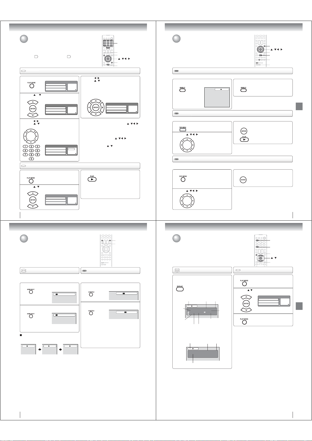
Advanced playback
Program playback/Random playback
You can arrange the playback order of tracks on the disc. And the
unit can also select tracks at random and playback them. These
features work for Video CD.
For Audio CD and MP3/WMA CD, please see “Random playback
52
(CD)”
and “Program playback (CD)” 53.
VCD
VCD
Program playback
Press PLAY MODE in the stop mode.
1
Press or to select “Mode”, then press
ENTER repeatedly to select “Program”.
2
Press / to select the programming position.
/ and then use
Press
3
to input the track.
•
• If you input a wrong number, press
EXIT/CANCEL.
CD
VCD
Random playback
Press PLAY MODE during playback or stop
mode.
1
Press / to select “Mode”, then press
ENTER repeatedly to select “Random”.
2
Play Mode
Mode : Off
Repeat : Off
Program Playback
Play Mode
Mode : Program
Repeat : Off
Program Playback
Number buttons (0–9)
To program others, repeat this step.
Play Mode
Mode : Program
Repeat : Off
Program Playback
Play Mode
Mode : Random
Repeat : Off
Program Playback
1 – – –
2 – – –
3 – – –
1 – – –
2 – – –
3 – – –
1 9
2 – – –
3 – – –
1 – – –
2 – – –
3 – – –
Press
press
4
and press ENTER.
The programs you selected will start to playback in order.
• To resume normal playback,
select Mode: “Off” in step 2.
To change the program
1. Select Mode to “Program” (as step 2), press
to select the track number you want to change, then
press EXIT/CANCEL.
2. Press Number buttons (0–9) to input the new track
number.
To clear the program one by one
Select Mode to “Program”, press
track number. Then press EXIT/CANCEL.
To clear all the programs
At the left column, press
Then press ENTER.
Notes:
• In playing back the Video CD with PBC, you cannot set
Program playback.
• The program is canceled when you eject the disc or turn the
power off.
Press PLAY
3
The Random Playback will start.
• If you set “Random” during playback mode,
Random playback will begin after the track that is
currently being played has ended.
• To resume normal playback,
select Mode: “Off” in step 2.
Note:
In case of Video CD with PBC, you cannot set Random
function during playback.
44
0–9
PLAY MODE
ENTER
/ / /
EXIT/CANCEL
PLAY
/
to return to the left column, then
/
to select the “Program Playback”
Play Mode
Mode : Program
Repeat : Off
Program Playback
/ / /
/
to select “Clear Program”.
.
1 9
2 3
3 11
/ / /
to select the
Changing angles/Title selection/DVD menu
DVD MENU
/
/ /
ENTER
PLAY
ANGLE
TOP MENU
Changing angles
When playing back a disc recorded with multi-angle facility, you can change the angle that you are viewing the scene from.
Press ANGLE during playback.
The current angle will appear.
1
1/2
Title selection
Two or more titles are recorded on some discs. If the title menu is recorded on the disc, you can select the desired title.
Press TOP MENU during playback.
1
2
Title menu appears on the screen.
Press / /
/ to select the desired title.
DVD menu
Some DVDs allow you to select the disc contents using the menu.
When you playback these DVDs, you can select the subtitle language and soundtrack language, etc. using the menu.
Press DVD MENU during playback.
1
2
The DVD menu appears on the TV
screen.
• Press DVD MENU again to resume
playback at the scene when you
pressed DVD MENU.
Press
/
/ / to select the desired item.
Press ANGLE repeatedly until the desired angle
is selected.
2
Note:
Depending on the DVD, you may not be able to change the
angles even if multi-angles are recorded on the DVD.
Press ENTER or PLAY.
3
Notes:
•
Depending on the DVD, you may not be able to select the title.
•
Depending on the DVD, a “title menu” may simply be called a
“menu” or “title” in the instructions supplied with the disc.
3
Note:
Depending on the DVD, you may not be able to resume playback
from the scene point when you press the DVD MENU button.
The playback of the selected title will
start.
Press ENTER.
The menu continues to another
screen. Repeat steps 2 and 3 to set
the item completely.
45
Advanced playback
Advanced playback
Changing soundtrack language/Subtitles
DVD
Changing soundtrack language
VCD
You can select the language when you play a multilingual disc.
Press AUDIO SELECT during playback.
1
2
In case of Video CD playback
Audio type changes as follows each time you press AUDIO
SELECT.
Notes:
• If the desired language is not heard after pressing the
button several times, the language is not recorded on
the disc.
• The selected soundtrack language is canceled when
you eject the disc. The initial default language or
available language will be heard if the disc is played
back again.
• If you select DTS in playing DTS-encoded disc, no
sound will be heard from the TV/DVD’s speakers.
The current soundtrack language will
appear.
Press AUDIO SELECT repeatedly until the
desired language is selected.
• The on screen display will disappear after a few
seconds.
LR
L
1/2 Eng Dolby Digital
2/2 Fre Dolby Digital
R
Subtitles
When playing back a disc recorded with subtitles, you can
select the subtitle language or turn the subtitle off.
Press SUBTITLE repeatedly during playback until
the desired language is selected.
1
To turn off the subtitle, press SUBTITLE until
“Off” appears.
2
• The on screen display will disappear after a
few seconds.
Notes:
• Depending on the DVD, you may not be able to change
subtitles, or to turn subtitles on or off.
• While playing a DVD, the subtitle may change when
you loaded or eject the disc.
• In some cases, a selected subtitle language may not
be changed immediately.
AUDIO SELECT
SUBTITLE
1/5 Eng
Off
Disc status/To turn off the PBC
DVD
Disc status
VCD
With press of DISPLAY, the status of the disc
will appear on the screen.
To cancel the display, press DISPLAY again.
DVD
DISC OPERATION
TITLE NO.
ANGLE NO.
AUDIO LANGUAGE A KIND OF AUDIO
Video CD
DISC OPERATION
ELAPSED
TIME
DVD 00:15:25 01:41:39
Title 1/3 Chapter 2/24
1/1 Eng Dolby Digital 1/2 Eng
1/1
SUBTITLE LANGUAGE
ELAPSED
TIME
VCD 00:08:32 00:51:03
Track 3/15
TRACK NO.
TOTAL
TIME
TOTAL
TIME
CHAPTER
NO.
1
DISPLAY
PLAY MODE
/
ENTER
VCD
To turn off the PBC
Press PLAY MODE in the stop mode.
1
Press / to select “Mode”, then press
ENTER repeatedly until “Off” appear.
2
Press PLAY MODE again to clear the screen.
3
To turn on the PBC
Follow the above steps 1~2, then press
until “PBC” appear.
Note:
You can also turn off the PBC by pressing number button 1
and ENTER in the stop mode.
Mode : Off
Repeat : Off
Play Mode
Program Playback
ENTER
(see page 7)
1 – – –
2 – – –
3 – – –
repeatedly
Advanced playback
46
47
Page 15
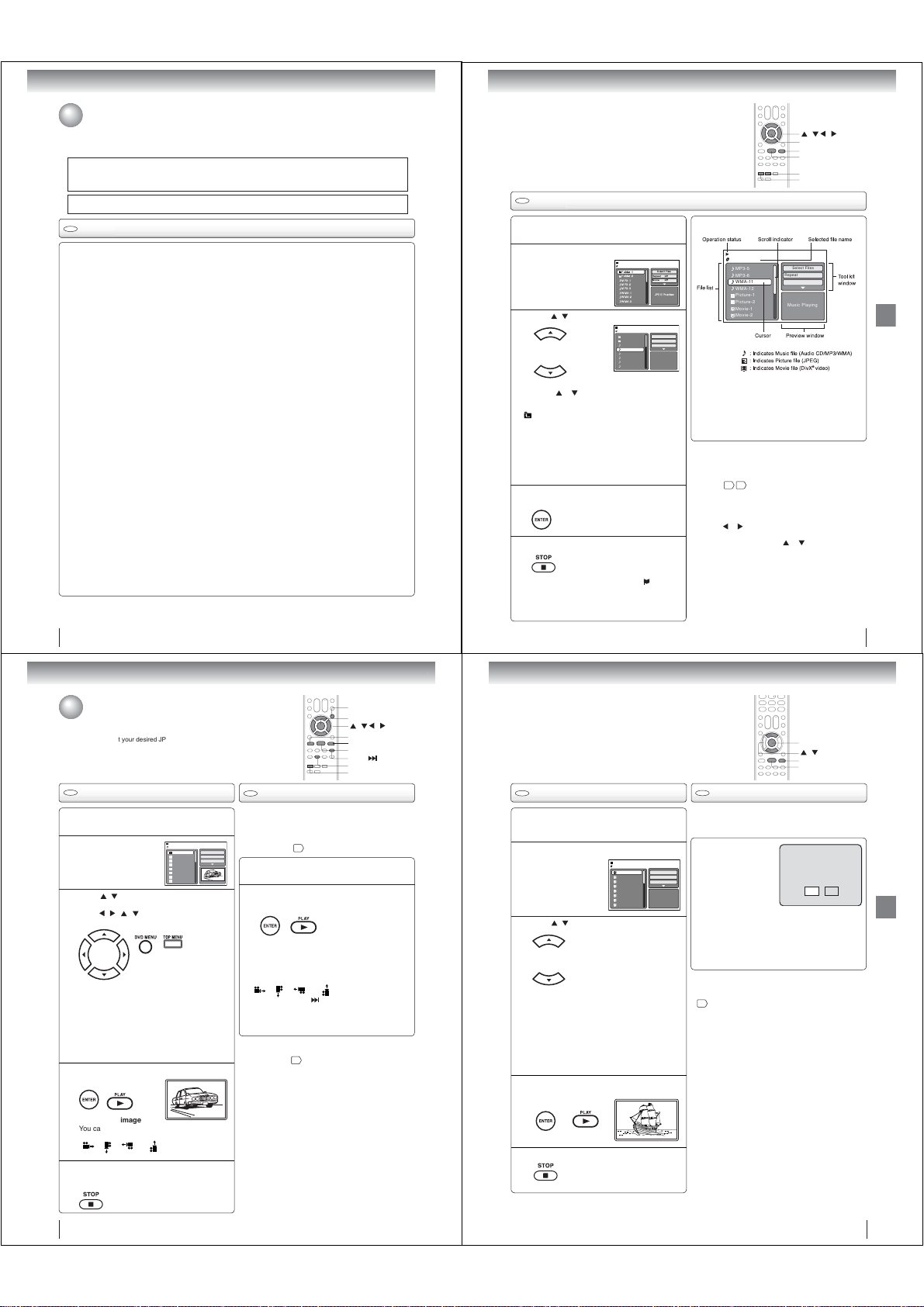
Advanced playback
MP3/WMA/JPEG/DivX® and Audio CD operation
This player can playback the MP3/WMA/JPEG/DivX®-data which has been recorded on CD-R or CD-RW. To produce
the MP3/WMA/JPEG/DivX
Software (not supplied). The Apple-HFS-System cannot be played.
This player requires discs/recordings to meet certain technical standards in order to achieve optimal playback quality.
There are many different types of recordable disc formats (including CD-R containing MP3/WMA fi les). Not all
recordable discs will produce optimal playback quality. The technical criteria set forth in this owner’s manual are meant
only as a guide. Use of CD-RW for MP3 fi les is not recommended.
You must obtain any required permission from copyright owners to download or use copyrighted content.
Toshiba cannot and does not grant such permission.
CD
Audio CD/MP3/WMA/JPEG/DivX® CD information
Limitations on MP3/WMA/JPEG/DivX® CD playback
• MP3/WMA/JPEG/DivX
letters, “.mp3”, “.wma”, “.jpg”, “.div”, “.divx”, “.avi”.
• MP3/WMA/JPEG/DivX
• This unit can read 600 fi les per directory. If one directory has more than 600 fi les, it reads up to 600 fi les, the remaining
fi les will be omitted.
• The unit is able to recognize up to a maximum of 50 directories per disc.
• MP3/WMA/JPEG/DivX
• If the CD has both CDA audio tracks and MP3/WMA/JPEG/DivX
• It may take more than one minute for this unit to read MP3/WMA/JPEG/DivX
• Music recorded by “Joliet Recording Specifi cation” can be played back, the fi le name is displayed (within 15 letters) on
the screen. Long fi le names will be condensed.
• The music fi les recorded by “Hierarchical File System” (HFS) cannot be played.
Limitations on display
• The maximum number for display is 15 letters.
Available letters for display are the following:
capital or small alphabets of A through Z, numbers of 0 through 9, and _ (under score).
• Other letters than those above are replaced in hyphen.
Notes on MP3/WMA/JPEG/DivX
To playback MP3/WMA/JPEG/DivX
1. Use MP3/WMA/JPEG/DivX
2. Name each fi le including two-digit or three-digit number (ex. “01” “02” or “001” “002”).
3. Refrain from making too many sub-folders.
CAUTION:
• Some MP3/WMA/JPEG/DivX
• The CD-R/RW that has no music data or non MP3/WMA/JPEG/DivX
Standard, sampling frequency and the bit rate:
MP3 CD
MPEG-1 Audio
32kHz, 44.1kHz, 48kHz
32kbps ~ 320kbps (constant bit rate or variable bit rate)
The recommend recording setting for a high-quality sound is 44.1kHz of sampling frequency and 128kbps of constant
bit rate.
WMA CD
WMA version 7 and 8
32kHz/48kbps, 44.1kHz/48kbps~192kbps, 48kHz/128kbps~192kbps
The fi le recorded by mono, 48kHz, 48 kbps is not available to this unit.
®
DivX
video
®
version: DivX® 3, 4, 5, and 6 (specifi cally 3.1.1, 4.1.2, 5.0.2, 5.0.5, 5.1.1, 5.2.1, 6.0 at Home Theater profi le).
DivX
Audio format: MPEG1 Layer2 (MP2), MPEG1 Layer3 (MP3)
Sampling frequencies: 32kHz, 44.1kHz, 48kHz
Bit rate: 32kbps ~ 320kbps
Resolution: Max 720 x 576 (at 25fps), Max 720 x 480 (at 30fps)
Microsoft, Windows Media, and Windows Logo are either registered trademarks or trademarks of Microsoft Corporation in the
United States and/or other countries.
DivX, DivX Certifi ed, and associated logos are trademarks of DivX, Inc. and are used under license.
48
®
-data, you need a Windows-PC with CD-RW drive and a MP3/WMA/JPEG/DivX®-encoding
®
CD is the disc that is standardized by ISO9660, its fi le name must include 3-digits extension
®
CD must be corresponded to the ISO standardized fi les.
®
CDs cannot be used for the purpose of recording.
®
fi les
®
CD in the recorded order,
®
software that records data alphabetically or numerically.
®
CDs cannot be played back depending on the recording conditions.
®
fi les, only the CDA audio tracks will be played.
®
fi les depending on its structure.
®
fi les cannot be played back.
CD
MP3/WMA CD playback
Load a disc on which MP3 or WMA fi les have
been recorded in the disc slot.
1
A fi le browser screen will appear on the screen.
2
Press / to select fi le.
3
• In case the current directory includes more than 8
• To see contents in folder, select the folder and then
4
5
• The unit records the stopped point. “ ” appears
• If you press STOP again or unload the disc, the unit
or to scroll in the fi le list.
fi les, press
press ENTER. To return to the parent directory, select
Go Up ...” then press ENTER.
“
• When PLAY is pressed after the fi le browser
displayed, playback begins automatically starting
from the fi rst fi le. In this case, if the fi rst fi le is an
MP3/WMA fi le, only MP3/WMA fi les are played back
in order. If the fi rst fi le is a JPEG fi le, the fi rst JPEG
fi le is played back. If the fi rst fi le is a
®
fi le
is played back. If there is no fi le at a
fi rst DivX
root directory, playback does not begin automatically.
Press ENTER.
The selected fi le starts playing back.
Press STOP to end playback.
on the TV screen. Press PLAY to resume playback
(from the scene point).
will clear the stopped point.
Folder-1
Folder-2
MP3-1
MP3-2
MP3-3
WMA-1
WMA-2
WMA-3
/MP3-2.MP3
Folder-1
Folder-2
MP3-1
MP3-2
MP3-3
WMA-1
WMA-2
WMA-3
DivX® fi le, the
Repeat :Off
Mode :Off
JPEGPreview
Repeat :Off
Mode :Off
JPEG Preview
SelectFiles
Select Files
/ / /
ENTER
STOP
PLAY
RETURN
TOP MENU
About fi le menu
3/15 00:00:00
/WMA-11.WMA
MP3-5
MP3-6
WMA-11
WMA-12
Picture-1
Picture-2
Movie-1
Movie-2
Notes:
• The thumbnail list is displayed when the FUJICOLOR CD
or the Kodak Picture CD are played. To display the fi le
browser, press TOP MENU.
• In the case of a CD containing a mixture of MP3, WMA,
JPEG and DivX
selecting them from the fi le browser.
• MP3 or WMA fi le on the Kodak Picture CD is not
recognized on this unit.
Notes:
• During MP3/WMA/JPEG/DivX
JUMP and A-B Repeat functions.
• You can use Repeat (Track or All), Random functions and
Program playback for Audio CD/MP3/WMA/JPEG/DivX
52 53
Playback
Select Files
The fi le type to make it display in the fi le browser can
be chosen.
1. Press
or to highlight “Select Files” at right
column in the fi le browser.
2 Press ENTER, then press
from the list (Music, Picture or Movie).
3. Press ENTER to add/remove check mark.
Checked fi le type will be displayed in the fi le browser.
4. Press RETURN to save the setting.
Select Files
Repeat :Off
Mode :Off
Music Playing
®
fi les, the fi les are played back by
®
Playback, you cannot use
.
or to select fi le type
®
CD
49
Advanced playback
Advanced playback
Advanced playback
MP3/WMA/JPEG/DivX® and Audio CD
operation (Continued)
You can select your desired JPEG fi le on the fi le menu and picture menu.
The selected JPEG fi le is automatically adjusted to the TV screen. (When
the aspect ratio of the JPEG fi le is different to the TV screen, the black bar
will appear at the top and bottom, or the both sides of the TV screen.)
CD
JPEG CD playback
Load a JPEG disc in the disc slot.
1
A fi le browser screen
will appear on the
2
screen.
Press
/
to select the fi le.
To display a thumbnail list, press DVD MENU.
3
Press
/ / /
(To return to the fi le browser, press TOP MENU.)
• When PLAY is pressed after displaying the
fi le browser, playback begins
starting from the fi rst fi le. In this case,
fi le is a JPEG fi le, the fi rst JPEG fi le is played
back. If the fi rst fi le is a DivX
®
DivX
fi le is played back.
If the fi rst fi le is an MP3/WMA fi le, only MP3/
WMA fi les are played back in order. If there is
no fi le at a root directory, playback does not
begin automatically.
Press ENTER or PLAY. The selected picture
appears on the screen.
4
Rotating an image
You can rotate an image by 90 degrees.
Press ANGLE during playback of the image.
“ ”, “ ”, “ ” or “ ” appears on the screen.
Press STOP to end playback.
The fi le browser appears on the screen. If you
5
want to watch the other fi le, repeat steps 3 ~ 4.
/Picture-01.JPG
Picture-01
Picture-02
Picture-03
Picture-04
Picture-05
Picture-06
Picture-07
Picture-08
to select the desired fi le.
automatically
®
fi le, the fi rst
if the fi rst
CD
Slide show playback
The slide show enables you to view pictures (fi les) one after
another automatically.
Preparation:
• Set “JPEG Interval” setting to “5 Seconds”, “10 Seconds”
or “15 Seconds”
Select Files
Repeat :Off
Mode :Off
JPEG Preview
W: 2048 H: 1536
Select your desired starting fi le for the slide
show in the step 3 on left.
1
Press ENTER or PLAY to start slide show from
the selected fi le.
2
•
If you press PAUSE during the slide show, the slide
show stops temporary. “
screen.
If the picture appears upside down or sideways, press
ANGLE repeatedly until it’s right side up.
”, “ ”, “ ” or “ ” appears on the TV screen.
“
Press PLAY or SKIP again to resume the slide show.
•
When the slide show playback fi nished, the fi le list
appears.
•
To stop the slide show, press STOP. The fi le list appears.
Notes:
• Zoom function can also be used in viewing JPEG fi les.
See “Zooming”
• During JPEG playback, you cannot use Jump and A-B
Repeat functions.
.
57
” appears briefl y on the TV
41
.
DVD MENU
ENTER
/ / /
PAUSE
STOP
PLAY
SKIP
ANGLE
TOP MENU
CD
DivX® CD playback
Load a disc on which DivX® fi les have been
recorded in the disc slot.
1
A fi le browser screen will appear on the TV
screen.
2
Press / to select fi le.
3
• When PLAY has been pressed after displaying
the fi le browser, playback begins automatically
starting from the fi rst fi le. In this case, if the
fi rst fi le is a JPEG fi le, the fi rst JPEG fi le is
played back. If the fi rst fi le is a
the fi rst DivX
fi le is an MP3/WMA fi le, only MP3/WMA fi le
are played back in order. If there is no fi le
at a root directory, playback does not begin
automatically.
Press ENTER or PLAY. The selected DivX®
movie will be played back on the TV screen.
4
Press STOP to end playback.
The fi le browser appears on the
5
/Movie-01.DIVX
Movie-01
Movie-02
Movie-03
Movie-04
Movie-05
Movie-06
Movie-07
Movie-08
®
fi le
TV screen. If you want to watch the
other fi le, repeat steps 3 ~ 4.
DivX® fi le,
is played back. If the fi rst
CD
Playing DivX® VOD content
DivX® VOD content is protected by DRM (Digital Rights
Management) system. This restricts playback of content
to specifi c registered devices.
If the incorrect DRM fi le
is loaded, “Authorization
Error This player is not
Select Files
authorized to play this
Repeat :Off
video.” will appear on the
Mode :Off
TV screen.
When you attempt to play
JPEG Preview
®
VOD, the number
DivX
of plays is limited and the
right message will appear on the TV screen. If you wish
to play it, select “Yes”.
• If the number of plays goes over the limit, then “Rental
Expired” will be displayed. In this case the fi le will not
be played.
Notes:
• In order to play DivX
need to register the unit with registration code. See page
.
59
• Depending on the recording conditions of DivX
may not be able to use FF, REV or JUMP function.
®
VOD content on this unit, you fi rst
ENTER
/
STOP
PLAY
View DivX® VOD Rental
This rental has 5 views left.
Do you want to use one
of your 5 views now?
NoYes
®
fi le, you
Advanced playback
50
51
Page 16
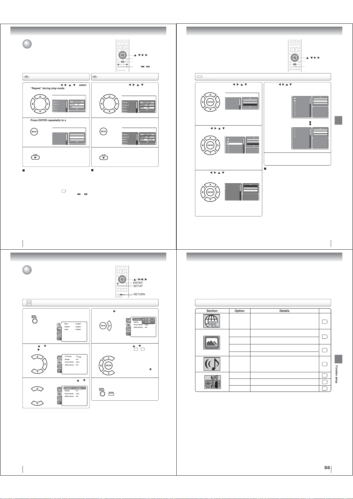
Advanced playback
F
F
M
M
F
F
M
M
w
Repeat, random and program playback
using fi le browser
CD CD
Repeat playback (CD)
In the fi le browser, press
“Repeat” during stop mode.
1
Press ENTER repeatedly to select “Track” or
“All”.
2 2
Press PLAY.
3
To resume normal playback
Select Repeat : “Off” in step 2.
Notes:
• The repeat or randam function is canceled when you eject
the disc or turn the power off.
• In case of Audio CD, the function of A-B Repeat can be
used. See “A-B Repeat playback”
• Track repeat function is canceled whenever SKIP
is pressed.
/ / /
to select
older-1
older-2
P3-1
P3-2
older-1
older-2
P3-1
P3-2
The unit automatically starts repeat
playback after fi nishing the current
track.
Select Files
Repeat :Off
Mode :Off
Select Files
Repeat :Track
Mode :Off
43
.
Random playback (CD)
In the fi le browser, press /
“Mode” during stop mode.
1
Press ENTER to select “Random”.
Press PLAY.
3
To resume normal playback
Select Mode : “Off” in step 2.
or
/ / /
ENTER
PLAY
SKIP /
/ /
to select
Folder-1
Folder-2
MP3-1
MP3-2
Folder-1
Folder-2
MP3-1
MP3-2
Select Files
Repeat :Off
Mode :Off
Select Files
Repeat :Off
Mode :Random
The Random playback will start.
CD
Program playback (CD)
In the fi le browser, press / / / to select
“Edit Mode”, then press ENTER.
1
Folder-1
Folder-2
MP3-1
MP3-2
When “Edit Mode” is black
color, you can mark the fi les
which you want to add into
Program list.
Press
/ / /
add into the program list.
2
Press
Then press ENTER. All marked fi les are added
3
into the program list.
to select fi le you want to
Folder-1
Folder-2
MP3-1
MP3-2
MP3-3
WMA-1
Press ENTER. Selected fi le
was marked.
Repeat this procedure to
select the other fi les.
/ / /
to select “Add To Program”.
Folder-1
Folder-2
MP3-1
MP3-2
MP3-3
WMA-1
When you fi nish storing the fi les
which you want into the Program
list, select “Edit Mode” and press
ENTER to release edit mode.
Repeat :Off
Mode :Off
Edit Mode
Repeat :Off
Mode :Off
JPEG Previe
Edit Mode
Program View
Add To Program
JPEG Preview
Press
/ / /
press ENTER. Program View shows only the
4
programed fi les that you have added in step 2.
Browser View
Edit Mode
Program View
In the Program View, press PLAY. The fi les
start to playback in programed order that were
5
added by you.
To remove fi le from program list in stop mode
In the Edit Mode, switch to Program View. Select fi le
you want to remove, then press ENTER. Select “Clear
Program” and press ENTER. Marked fi le is removed
from program list.
Note:
The program function is canceled when you eject the disc or
turn the power off.
to select “Program View”, then
Folder-1
Folder-2
MP3-1
MP3-2
MP3-3
WMA-1
WMA-2
WMA-3
MP3-1
MP3-2
MP3-3
WMA-3
/ / /
ENTER
PLAY
Edit Mode
Program View
Add To Program
JPEG Preview
Edit Mode
Browser View
Clear Program
JPEG Preview
Advanced playback
52
Function setup
Customizing the function settings
You can change the default settings of the DVD mode to customize
performance to your preference.
DVD
VCD
Setting procedure
CD
Press SETUP during stop mode.
1
The following on-screen display appears.
Parental : Off
DRC : Off
E.B.L. : Off
Menu : English
Set Password
QSound : On
TV Screen : 4:3
Subtitle : English
Output : Interlace
Display : On
Audio : English
DivX(R) VOD
Picture Mode : Auto
JPEG Interval : 5 Seconds
Screen Saver : On
Press or to select the desired section, then
press .
2
First option will be highlighted. Press or
to select the desired option.
3
Parental : Off
DRC : Off
Menu : English
TV Screen : 4:3
Set Password
QSound : On
Subtitle : English
Display : On
Output : Interlace
Audio : English
Picture Mode : Auto
DivX(R) VOD
JPEG Interval : Off
Parental : Off
DRC : Off
Menu : English
TV Screen : 4:3
Set Password
QSound : On
Subtitle : English
Display : On
Output : Interlace
Audio : English
Picture Mode : Auto
DivX(R) VOD
JPEG Interval : Off
/ / /
ENTER
SETUP
RETURN
Then press or ENTER. The selectable
settings will appear.
4
Change the selection using or , by referring
to the corresponding pages
5
Press ENTER to save the setting.
To clear SETUP screen, press SETUP or
RETURN.
6
Parental : Off
DRC : Off
Menu : English
TV Screen 4:3
Set Password
QSound : On
Subtitle : English
Display 4:3
Output : Interlace
Audio : English
Picture Mode : Auto
DivX(R) VOD
JPEG Interval : Off
56
~ 59.
•
Repeat steps 3 and 5 to change
other option.
•
To select another section, go
back to step 2 by pressing
repeatedly.
Setting details
Section Option Details Page
Menu
Subtitle
Audio
TV Screen
Display
Picture Mode
JPEG Interval To select a preferred setting for the slide show playback.
DRC To select On or Off for DRC (Dynamic Range Control).
Parental
Password To change the password.
DivX(R) VOD To display your 8-character registration code.
To select the language of “Menu”, “Subtitle” and “Audio”
if more than one language are available on the disc.
To select a picture size according to the aspect ratio of
your TV.
To turn On or Off the operational status display on the TV
screen.
To select a preferred picture mode from “Video”, “Film” or
“Auto”.
To select a preferred parental level for the parental setting.
53
56
56
57
58
58
59
59
Function setup
54
55
Page 17
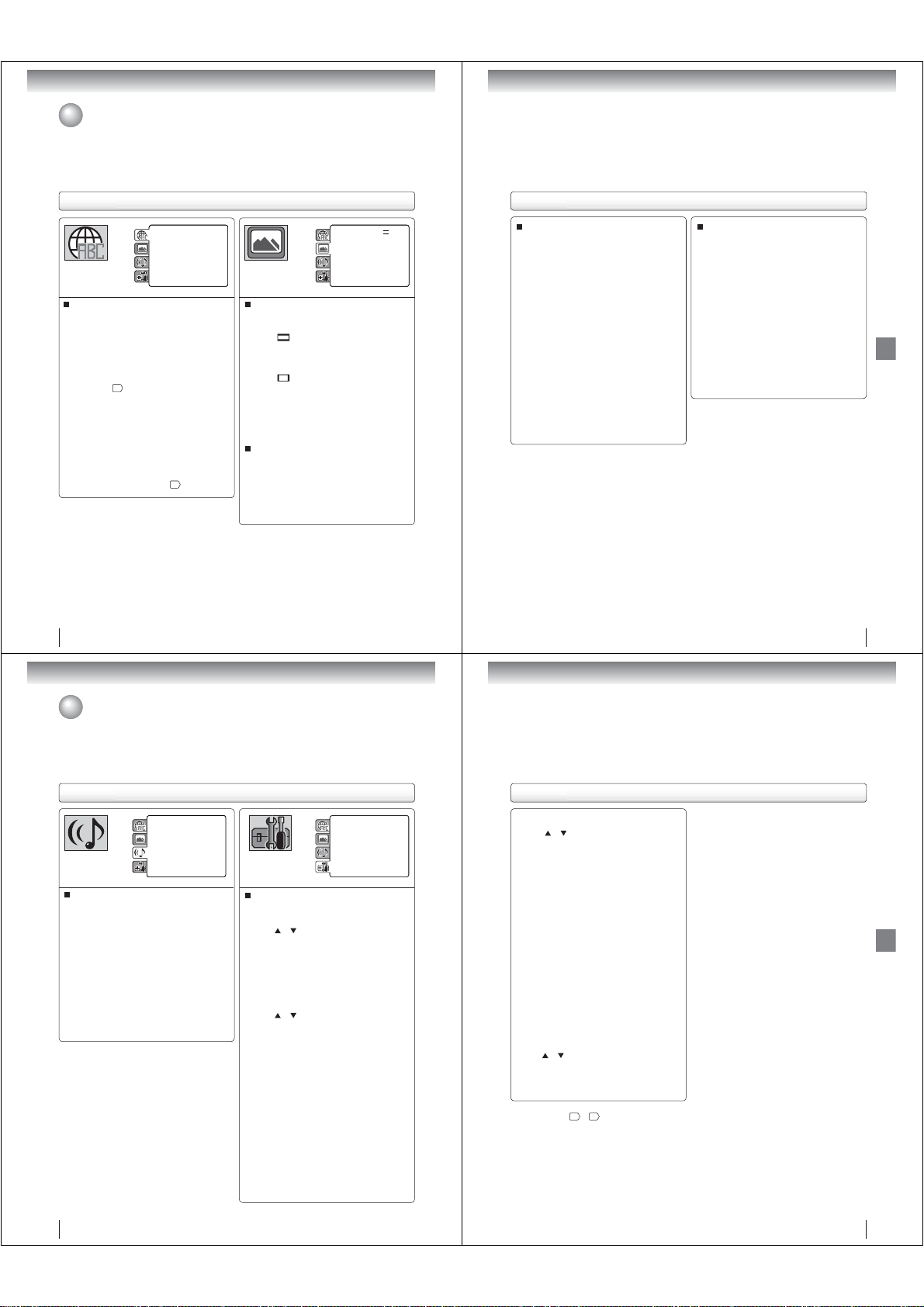
Function setup
Customizing the function settings (Continued)
Setting details
Parental : Off
DRC : Off
E.B.L. : Off
Menu : English
Set Password
QSound : On
TV Screen : 4:3
Subtitle : English
Output : Interlace
Display : On
Audio : English
DivX(R) VOD
Picture Mode : Auto
JPEG Interval : 5 Seconds
Screen Saver : On
Menu, Subtitle, Audio
You can select the language of “Menu”, “Subtitle” and
“Audio” if more than one languages are recorded onto
the disc.
English, Francais, Espanol:
The selected language will be heard or seen.
Other:
Other language can be selected (see “Language
61
code list”
).
Original (Audio):
The unit will select the fi rst priority language of
each disc.
Off (Subtitle):
Subtitles do not appear.
Notes:
• If the selected language is not recorded on the disc, the
fi rst-priority language is selected.
• If you want to change the on screen display language, you
can perform it by TV SETUP MENU
20
.
56
Parental : Off
DRC : Off
Menu : English
TV Screen : 4:3
Set Password
QSound : On
Subtitle : English
Display : On
Output : Interlace
Audio : English
Picture Mode : Auto
DivX(R) VOD
JPEG Interval : Off
TV Screen
You have the following screen sizes to choose from:
4:3
When playing back a wide screen-DVD disc, it
displays the wide picture with black bands at the
top and bottom of screen.
4:3
It displays the wide picture on the whole screen
with left and right edges automatically cut off.
Note:
If the DVD disc is not formatted in the Pan & scan style,
it will display 4:3 style.
(Letter box):
(Pan & scan):
Display
On screen display can be switched on or off when you
press any buttons.
On: On screen displays appear when you press
the buttons (factory setting).
Off: On screen displays do not appear when you
press any buttons.
Setting details
Picture Mode
There are two types of source content in pictures
recorded in DVD video discs: fi lm content (pictures
recorded from fi lms at 24 frames per second) and
video content (video signals recorded at 30 frames per
second). Make this selection according to the type of
content being viewed.
Auto: Select this selection normally.
The DVD player automatically detects
source content, fi lm or video of
playback source, and converts that
signal in an appropriate method.
Film: The DVD player converts fi lm content
pictures appropriately. Suitable for
playback of fi lm content pictures.
Video: The DVD player fi lters video signal and
converts it appropriately.
Suitable for playback of video content
pictures.
Note:
Depending on the disc, pictures may be cut off or
doubled. In this case, select “Video”.
JPEG Interval
You can continuously playback all JPEG fi les
automatically.
After the selection below, the disc will start playback on
JPEG fi les which have been recorded.
Off:
Plays back one fi le at a time.
5 Seconds:
Plays back images in the form of a slide show at
5 second intervals.
10 Seconds:
Plays back images in the form of a slide show at
10 second intervals.
15 Seconds:
Plays back images in the form of a slide show at
15 second intervals.
57
Function setup
Function setup
Customizing the function settings (Continued)
Setting details
Parental : Off
E.B.L. : Off
DRC : Off
Set Password
TV Screen : 4:3
Output : Interlace
Display : On
DivX(R) VOD
Picture Mode : Auto
JPEG Interval : 5 Seconds
Screen Saver : On
DRC
DRC (Dynamic Range Control) enables you to control
the dynamic range so as to achieve a suitable sound
for your equipment.
Off:
It plays back at the recording level on the disc.
On:
Loud sound such as explosion is toned down
slightly when played back. This is suitable when
it is connected to a stereo.
Notes:
• This function works only during playback of Dolby Digital
recorded discs.
• The level of Dynamic Range Reduction may differ
depending on DVD video disc.
Parental control setting
Some discs are specifi ed as not suitable for children.
Such discs can be limited not to playback with the unit.
or to select “Parental”, then press
1) Press
ENTER. “Enter Password” screen will appear.
2) Press “0000” using Number buttons (0–9).
(Please note, this is pre-setting password of this
unit). Then press ENTER. The parental level list
will appear.
• Level Off: The parental control setting does not
function.
• Level 8:
• Level 1: DVD software for adults cannot be
played back.
3) Press
The limitation will be more severe as the level
number is lower. Then press ENTER.
Notes:
• The parental control level is equivalent to the following
Level 1: G Level 5:
Level 2: Level 6: R
Level 3: PG Level 7: NC-17
Level 4: PG-13 Level 8:
The parental control levels for other countries/area
than U.S. are included for future use. Check the
appropriate parental control level when you buy a DVD
•
• Some discs may not be encoded with specifi c rating
level information though its disc jacket says “adult.”
For those discs, the age restriction will not work.
• The password is required every time when you
• If you input a wrong number, press EXIT/CANCEL.
All DVD software can be played back.
or to select from the level 1 to level 8.
USA movie ratings.
video disc equipped with the parental control feature
in the future.
Depending on the discs, the unit cannot limit playback.
change the parental level.
DRC : Off
Menu : English
E.B.L. : Off
Parental : Off
QSound : On
Subtitle : English
TV Screen : 4:3
Password : Change
Audio : English
Display : On
DivX(R) VOD : Display
Picture Mode : Auto
JPEG Interval : 5 Seconds
Screen Saver : On
Setting details
Set the new password
or to select “Password”, then press
1) Press
ENTER. “Enter Current Password” screen will
appear.
2) Press Number buttons (0–9) to input the current
password (If the password has not been set yet
after you purchase this unit, it is “0000”).
3) Then press ENTER. “Enter New Password” screen
will appear. Press Number buttons (0–9) to input
the new password.
4) Press ENTER. Now your new password has been
set. Be sure to remember this number!
If you forget the password
1) Press EJECT to remove the disc.
2) While holding 7 down on the remote control and
then press STOP on the unit. “Password Clear”
appears on the screen. Now the password
has been returned to the initial value (“0000”).
DivX® VOD
In order to play DivX
on this unit, you fi rst need to register the unit with your
DivX
a DivX
your provider.
Press
ENTER. Your 8-character registration code is
displayed. Make a note of the code as you will need
it when you register with a DivX
Then press ENTER to select Done.
Note:
If each setup (pages
always work under the same condition (especially with DVD
discs).
Each setup will be retained in the memory even if you turn the
power off.
®
®
VOD (Video On Demand) content
VOD content provider. You do this by generating
®
VOD registration code, which you submit to
or to select “DivX(R) VOD”. Then press
®
VOD provider.
56
~ 59) has completed, the unit can
Function setup
58
59
Page 18
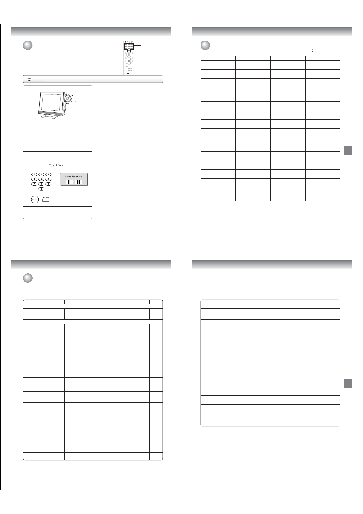
Function setup
Temporary cancel the rating level by DVD disc
Depending on the DVD disc, the disc may try to temporarily cancel the rating level
that you have set.
It is up to you to decide whether to cancel the rating level or not.
DVD
Temporary cancel the rating level by DVD disc
Load a DVD disc.
1
If the DVD disc has been designed to
temporarily cancel the Rating level, the screen
2
which follows the “Reading” screen will
change, depending on which disc is played.
If you select “YES” with the ENTER key,
password input screen will then appear.
• If “NO” is selected, press EJECT to remove
the disc.
Enter the password with Number buttons (0–9).
Then press ENTER.
3
To exit from the entry, press
RETURN.
Enter Password
Playback will commence if the entered
password is correct.
4
Note:
This temporary cancellation of rating level will be kept until
the disc is ejected.
When the disc is ejected, the original rating level will be set
again automatically.
EJECT
0–9
ENTER
RETURN
Others
Language code list
Enter the appropriate code number for the initial settings “Menu”, “Subtitle” and/or “Audio” 56.
Language Name Code Language Name Code Language Name Code Language Name Code
Abkhazian 1112 Fiji 1620 Lingala 2224 Singhalese 2919
Afar 1111 Finnish 1619 Lithuanian 2230 Slovak 2921
Afrikaans 1116 French 1628 Macedonian 2321 Slovenian 2922
Albanian 2927 Frisian 1635 Malagasy 2317 Somali 2925
Amharic 1123 Galician 1722 Malay 2329 Spanish 1529
Arabic 1128 Georgian 2111 Malayalam 2322 Sundanese 2931
Armenian 1835 German 1415 Maltese 2330 Swahili 2933
Assamese 1129 Greek 1522 Maori 2319 Swedish 2932
Aymara 1135 Greenlandic 2122 Marathi 2328 Tagalog 3022
Azerbaijani 1136 Guarani 1724 Moldavian 2325 Tajik 3017
Bashkir 1211 Gujarati 1731 Mongolian 2324 Tamil 3011
Basque 1531 Hausa 1811 Nauru 2411 Tatar 3030
Bengali; Bangla 1224 Hebrew 1933 Nepali 2415 Telugu 3015
Bhutani 1436 Hindi 1819 Norwegian 2425 Thai 3018
Bihari 1218 Hungarian 1831 Oriya 2528 Tibetan 1225
Breton 1228 Icelandic 1929 Panjabi 2611 Tigrinya 3019
Bulgarian 1217 Indonesian 1924 Pashto, Pushto 2629 Tonga 3025
Burmese 2335 Interlingua 1911 Persian 1611 Turkish 3028
Byelorussian 1215 Irish 1711 Polish 2622 Turkmen 3021
Cambodian 2123 Italian 1930 Portuguese 2630 Twi 3033
Catalan 1311 Japanese 2011 Quechua 2731 Ukrainian 3121
Chinese 3618 Javanese 2033 Rhaeto-Romance 2823 Urdu 3128
Corsican 1325 Kannada 2124 Romanian 2825 Uzbek 3136
Croatian 1828 Kashmiri 2129 Russian 2831 Vietnamese 3219
Czech 1329 Kazakh 2121 Samoan 2923 Volapük 3225
Danish 1411 Kirghiz 2135 Sanskrit 2911 Welsh 1335
Dutch 2422 Korean 2125 Scots Gaelic 1714 Wolof 3325
English 1524 Kurdish 2131 Serbian 2928 Xhosa 3418
Esperanto 1525 Laothian 2225 Serbo-Croatian 2918 Yiddish 2019
Estonian 1530 Latin 2211 Shona 2924 Yoruba 3525
Faroese 1625 Latvian, Lettish 2232 Sindhi 2914 Zulu 3631
Others
60
Others
Troubleshooting
Use the following check list for troubleshooting when you have problems with your unit. Consult your local dealer or
service outlet if problems persist.
Be sure all connections are properly made when using with other units.
SYMPTOMS POSSIBLE SOLUTIONS PAGE
POWER
TV/DVD does not operate.
TV BROADCAST RECEPTION
Poor sound or No sound.
Poor picture or No picture.
Poor reception on some
channels.
Poor color or no color.
Picture wobbles or drifts.
No CATV reception.
Horizontal or diagonal bars on
screen.
No reception above channel 13.
TV shuts off.
Closed - Caption is not
activated.
Display is not shown in your
language.
• Make sure the connection of AC cord is secured.
• Try another AC outlet.
• Unplug unit, then plug it back in.
• Station or Cable TV may have problems, try another station.
• Check Volume adjustments.
• Check for sources of possible interference.
• Station or Cable TV may have problems, try another station.
• Check antenna or Cable TV connections, reorient antenna.
• Check for sources of possible interference.
• Check picture control adjustments.
• Station or Cable TV may have problems, try another station.
• Station signal is weak, reorient antenna to receive weaker station.
• Check for sources of possible interference.
• Station or Cable TV may have problems, try another station.
• Make sure channels are set into memory.
• Check picture control adjustments.
• Check antenna or Cable TV connections, reorient antenna.
• Check for sources of possible interference.
• Station or Cable TV may have problems, try another station.
• Make sure channels are set into memory.
• Cable TV company is scrambling signal.
• Check antenna or Cable TV connections, reorient antenna.
• Check all Cable TV connections.
• Set TV/CABLE selection to the CABLE position.
• Station or Cable TV system problems, try another station.
• Check antenna or Cable TV connections, reorient antenna.
• Check for sources of possible interference.
• Make sure TV/CABLE selection is in the appropriate position.
• If antenna is used, check UHF antenna connections.
• No broadcast on station tuned.
• Auto shut off feature worked.
• Sleep Timer is set.
• Power interrupted.
• TV station experiencing problems or program tuned is not closed
captioned. Try another channel.
• Check Cable TV connection or VHF/UHF antenna, reposition or
rotate antenna.
• Press CLOSED CAPTION button to turn on the closed caption
decoder.
• Select proper language in the menu options. 20
13,14
13,14
13,14
13,14
13,14
61
SYMPTOMS POSSIBLE SOLUTIONS PAGE
DVD
18
22
22
64
22
64
33
22
13
64
22
21
33
64
22
21
-
14
21
22
64
21
13
22
37
23
-
22
25
Playback doesn’t start.
No picture. • TV/DVD selector is not set correctly. 38
No sound.
Picture is distorted during fast
reverse/forward playback.
Stopping playback, search,
slowmotion play, repeat play, or
program play, etc. cannot be
performed.
No on-screen display. • Set Display to On. 56
The unit or remote operation key
is not functioning.
Playback does not start when
the title is selected.
Audio soundtrack and/or subtitle
language is not changed when
you playback a DVD.
No subtitle.
Angle cannot be changed. • Multi-angles are not recorded on the DVD disc. 45
“ ” appears on the screen. • The function is prohibited with the unit or the disc. 40
REMOTE CONTROL
The remote control does not
function.
• No disc is loaded.
• The disc may be dirty. Clean up the disc.
• The unit cannot play CD-ROMs, etc.
• Check the input selector of the amplifi er is set properly.
• The unit is in the special playback mode.
• Select the correct Audio Input/Output position on AV amplifi er.
• The picture will be distorted occasionally. -
• Some discs may not do some of the functions. -
• Turn off the unit and unplug the AC power cord for several minutes,
then replug it.
• Check the RATING LEVEL setup. 58
• Multilingual language is not recorded on the DVD disc. 46
• Some discs have no subtitles.
• Subtitles are cleared. Press the SUBTITLE button.
• Aim the remote control at the remote sensor.
• Operate within approx. 5 meters or reduce the light in the room.
• Clear the path of the beam.
• The batteries are weak. Replace the batteries.
• Check the batteries are inserted correctly.
17, 18
38
6
7
-
40
-
Others
46
12
62
63
Page 19
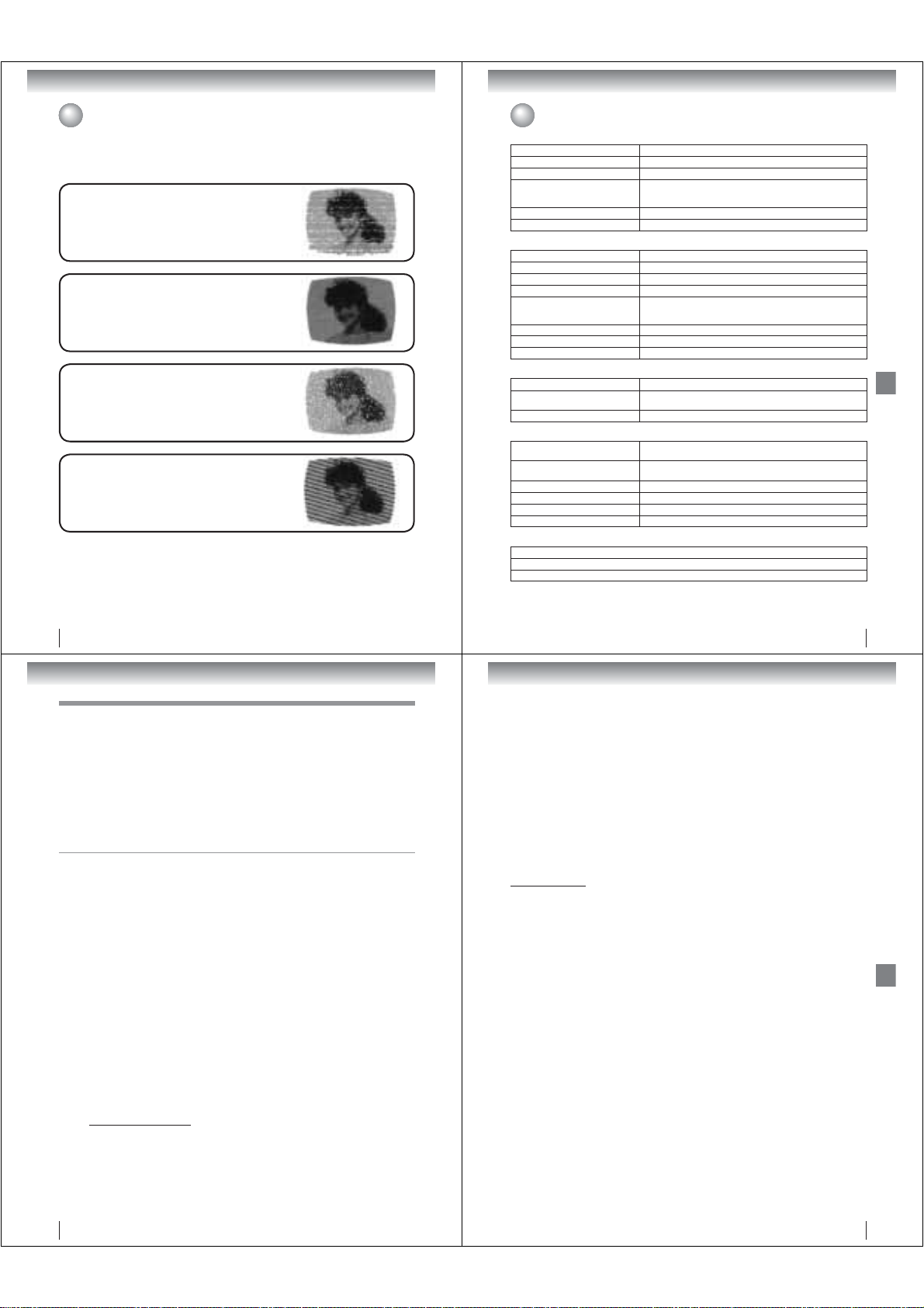
Others
Reception disturbances
Most types of television interference can be remedied by adjusting the height and position of the VHF/UHF antenna.
Outdoor antennas are recommended for best results. The most common types of television interference are shown
below. If one of these symptoms appear when the TV/DVD is connected to a Cable TV system, the disturbance may
be caused by the local Cable TV company broadcast.
IGNITION
Black spots or horizontal streaks may appear, the picture may fl utter or
drift. Usually caused by interference from automobile ignition systems,
neon lamps or AC powered tools and appliances such as drills or hair
dryers.
GHOSTS
Ghosts are caused by the television signal following two paths. One is
the direct path and the other is refl ected by tall buildings, hills or other
large objects. Changing the direction or position of the antenna may
improve the reception.
SNOW
If the TV/DVD is located far from the TV station, in a fringe reception
area where the signal is weak, small dots may appear in the picture.
If the signal is extremely weak, the installation of a larger external
antenna may be necessary.
RADIO FREQUENCY INTERFERENCE (RFI)
Caused by two-way radios, this type of interference produces moving
ripples or diagonal streaks in the picture. Some cases may cause a
loss of contrast in the picture. Changing the direction and position of
the antenna or installing an RFI fi lter may improve the picture.
CARE AND MAINTENANCE
To prevent fi re or shock hazard, disconnect the TV/DVD from the power source before cleaning.
Use caution when cleaning or wiping the plastic parts.
64
Specifi cations
General
Power supply AC 120V 60Hz
Power consumption Operation: 50 W, Stand by: 1 W
Weight 12.1 lbs (5.5 kg)
Dimensions
Operating temperature 5°C-40°C (41°F-104°F)
Operating humidity Less than 80% RH (No condensation)
Television
LCD panel 15-inch diagonal (Screen size is approximate.)
Display method Color TFT LCD
Number of pixels 1024 (Horizontal) x 768 (Vertical)
Television system NTSC standard, ATSC standard (8VSB), QAM
Receiving channels
Antenna input VHF/UHF 75
Speaker 1-1/2 x 2-11/16 inches (38.1 x 68.6 mm), 8 x 2
Audio output power 1.0W + 1.0W
DVD/CD Player
Signal system NTSC
Applicable disc
Pickup 1-Lens, 2-Beams System
Input/Output
S-Video input
ColorStream video input
Video input 1.0 V (p-p), 75 , negative sync., pin jack x 2
Audio input –8dBm, 50 k , negative sync., pin jack (L/R) x 2
Digital audio output (Coaxial) 0.5 V (p-p), 75 , pin jack x 1
Headphone ø3.5mm stereo mini jack x 1
Accessories
Remote control (DC-LWB1) ............................................. 1
Batteries (R03/AAA) ........................................................ 2
Owner’s manual (this booklet) ......................................... 1
• This model complies with the above specifi cations.
• Designs and specifi cations are subject to change without notice.
• This model may not be compatible with features and/or specifi cations that may be added in the future.
Width: 15-1/2 inches (394 mm)
Height: 15-1/16 inches (381.8 mm)
Depth: 7-1/2 inches (190 mm)
VHF: 2-13
UHF: 14-69
CATV: 1-125 (4A, A-5~A-1, A~I, J~W, W+1~W+84)
1. DVD (12cm, 8cm)
2. CD (12cm, 8cm)
(Y) 1.0 V (p-p), 75 , negative sync., Mini DIN 4-pin x 1
(C) 1.0 V (p-p), 75
(Y) 1.0 V (p-p), 75 , negative sync., pin jack x 1
(P
B, PR) 0.7 V (p-p), 75 , pin jack x 2
Others
65
Others
Limited United States Warranty
LCD TV/DVD Combination - Depot Repair Warranty
Toshiba America Consumer Products, L.L.C. (“TACP”) makes the following limited warranties to original
consumers in the United States. THESE LIMITED WARRANTIES EXTEND TO THE ORIGINAL CONSUMER
PURCHASER OR ANY PERSON RECEIVING THIS LCD TV/DVD COMBINATION AS A GIFT FROM THE
ORIGINAL CONSUMER PURCHASER AND TO NO OTHER PURCHASER OR TRANSFEREE.
LCD TV/DVD COMBINATIONS PURCHASED IN THE U.S.A. AND USED ANYWHERE OUTSIDE
OF THE U.S.A., INCLUDING, WITHOUT LIMITATION, CANADA AND MEXICO, ARE NOT COVERED
BY THESE WARRANTIES.
LCD TV/DVD COMBINATIONS PURCHASED ANYWHERE OUTSIDE OF THE U.S.A., INCLUDING,
WITHOUT LIMITATION, CANADA AND MEXICO, AND USED IN THE U.S.A., ARE NOT COVERED
BY THESE WARRANTIES.
Limited One (1) Year Warranty on Parts and Labor
TACP warrants this LCD TV/DVD Combination
and its parts against defects in materials or
workmanship for a period of one (1) year after
the date of original retail purchase. DURING
THIS PERIOD, TACP WILL, AT TACP’S OPTION,
REPAIR OR REPLACE A DEFECTIVE PART WITH
A NEW OR REFURBISHED PART WITHOUT
CHARGE TO YOU.
Rental Units
The warranty for LCD TV/DVD Combination rental
units begins on the date of the fi rst rental or thirty
(30) days after the date of shipment to the rental
fi rm, whichever comes fi rst.
Commercial Units
LCD TV/DVD Combinations sold and used for
commercial purposes have a limited warranty for all
parts and labor, which warranty begins on the date
of original retail purchase and ends on the date that
is ninety (90) days thereafter.
Owner’s Manual and Product Registration Card
Read this owner’s manual thoroughly before operating
this LCD TV/DVD Combination.
Complete and mail the enclosed product registration
card or register your LCD TV/DVD Combination
online at www.tacp.toshiba.com/service as soon as
possible. By registering your LCD TV/DVD
Combination you will enable TACP to bring you
new products specifi cally designed to meet your
needs and help us to contact you in the unlikely
event a safety notifi cation is required under the
U.S. Consumer Product Safety Act. Failure to
complete and return the product registration card
does not diminish your warranty rights.
Your Responsibility
THE ABOVE WARRANTIES ARE SUBJECT TO
THE FOLLOWING CONDITIONS:
(1) You must retain your bill of sale or provide
other proof of purchase.
(2) All warranty servicing of this LCD TV/DVD
Combination must be made by the Depot
Warranty Repair Center specifi ed by the TACP
Consumer Solutions Center.
(3) The warranties from TACP are effective only
if the LCD TV/DVD Combination is purchased
and operated in the Continental U.S.A. or
Puerto Rico.
(4) Labor service charges for set installation,
setup, adjustment of customer controls, and
installation or repair of antenna systems are not
covered by this warranty. Reception problems
caused by inadequate antenna systems are
your responsibility.
(5) Warranties extend only to defects in materials
or workmanship as limited above, and do not
extend to any LCD TV/DVD Combination or
parts that have been lost or discarded by you
or to damage to the LCD TV/DVD Combination
or parts caused by fi res, misuse, accident,
Acts of God (such as lightning or fl uctuations in
electric power), improper installation, improper
maintenance, or use in violation of instructions
furnished by TACP; use or malfunction
through simultaneous use of this LCD TV/DVD
Combination and connected equipment; or to
units that have been modifi ed or had the serial
number removed, altered, defaced, or rendered
illegible.
How to Obtain Warranty Services
If, after following all of the operating instructions
in this manual and checking the section
“Troubleshooting,” you fi nd that service is needed:
(1) For instructions on how to obtain warranty
service for your LCD TV/DVD Combination,
contact TACP’s Consumer Solution Center toll
free at 1-800-631-3811.
(2) You must include a copy or original bill of
sale or other proof of purchase along with
the entire LCD TV/DVD Combination to the
Depot Warranty Repair Center specifi ed by
the TACP Consumer Solutions Center. You
are responsible for all inbound transportation
and insurance charges for the LCD TV/DVD
Combination to the Depot Warranty Repair
Center specifi ed by the TACP Consumer
Solutions Center.
For additional information, visit TACP’s website:
www.tacp.toshiba.com
ALL WARRANTIES IMPLIED BY THE LAW OF
ANY STATE OF THE U.S.A., INCLUDING THE
IMPLIED WARRANTIES OF MERCHANTABILITY
AND FITNESS FOR A PARTICULAR PURPOSE,
ARE EXPRESSLY LIMITED TO THE DURATION
OF THE LIMITED WARRANTIES SET FORTH
ABOVE. WITH THE EXCEPTION OF ANY
WARRANTIES IMPLIED BY THE LAW OF ANY
STATE OF THE U.S.A. AS HEREBY LIMITED,
THE FOREGOING WARRANTY IS EXCLUSIVE
AND IN LIEU OF ALL OTHER WARRANTIES,
GUARANTEES, AGREEMENTS, AND SIMILAR
OBLIGATIONS OF TACP WITH RESPECT TO
THE REPAIR OR REPLACEMENT OF ANY
PARTS. IN NO EVENT SHALL TACP BE LIABLE
FOR CONSEQUENTIAL OR INCIDENTAL
DAMAGES (INCLUDING, BUT NOT LIMITED TO,
LOST PROFITS, BUSINESS INTERRUPTION, OR
MODIFICATION OR ERASURE OF RECORDED
DATA CAUSED BY USE, MISUSE OR INABILITY
TO USE THIS LCD TV/DVD COMBINATION).
No person, agent, distributor, dealer, or company
is authorized to change, modify, or extend
the terms of these warranties in any manner
whatsoever. The time within which an action must
be commenced to enforce any obligation of TACP
arising under the warranty or under any statute
or law of the United States or any state thereof is
hereby limited to ninety (90) days from the date
you discover, or should have discovered, the
defect. This limitation does not apply to implied
warranties arising under state law.
THIS WARRANTY GIVES YOU SPECIFIC LEGAL
RIGHTS AND YOU MAY ALSO HAVE OTHER
RIGHTS WHICH MAY VARY FROM STATE TO
STATE IN THE U.S.A. SOME STATES OF THE
U.S.A. DO NOT ALLOW LIMITATIONS ON HOW
LONG AN IMPLIED WARRANTY LASTS, WHEN
AN ACTION MAY BE BROUGHT, OR THE
EXCLUSION OR LIMITATION OF INCIDENTAL
OR CONSEQUENTIAL DAMAGES, SO THE
ABOVE PROVISIONS MAY NOT APPLY TO YOU
UNDER SUCH CIRCUMSTANCES.
Others
66
67
Page 20
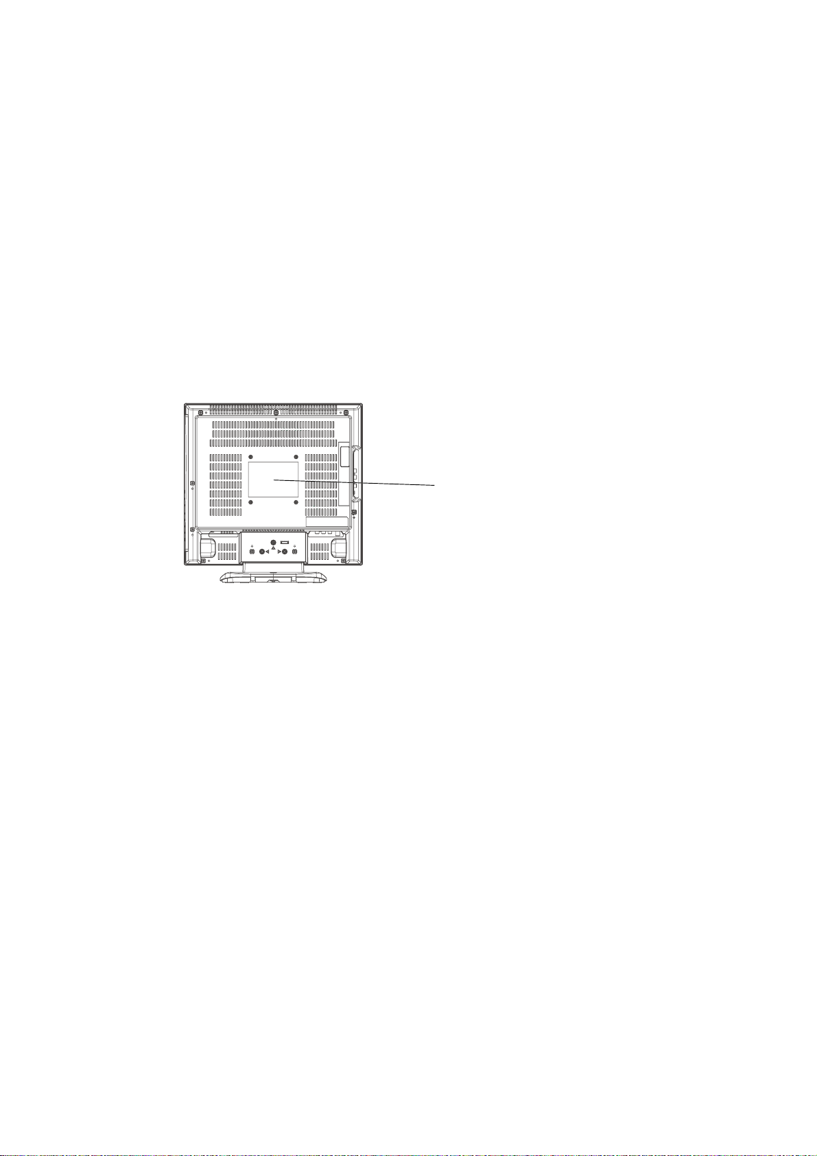
CAUTION
THIS
LCD COLOR TELEVISION
TO ENSURE PROPER USE OF THIS PRODUCT, PLEASE READ THIS SERVICE MANUAL CAREFULLY AND RETAIN FOR FUTURE REFERENCE. SHOULD THE UNIT REQUIRE MAINTENANCE,
CONTACT AN AUTHORIZED SER VICE LOCATION-SEE SERVICE PROCEDURE.
USE OF CONTROLS, ADJUSTMENTS OR THE PERFORMANCE OF PROCEDURES OTHER THAN
THOSE SPECIFIED HEREIN MAY RESULT IN HAZARDOUS LASER RADIATION EXPOSURE.
TO PREVENT DIRECT EXPOSURE TO LASER BEAM, DO NOT TRY TO OPEN THE ENCLOSURE.
VISIBLE LASER RADIA TION MAY BE PRESENT WHEN THE ENCLOSURE IS OPENED. DO NOT
ST ARE INTO BEAM.
Location of the required Marking
The rating sheet and the safety caution are on the rear of the unit.
EMPLOYS A LASER SYSTEM.
CERTIFICATION: COMPLIES WITH FDA
RADIA TION PERFORMANCE STANDARDS,
21 CFR SUBCHAPTER J.
PREPARATION OF SERVICING
The laser diode used for a pickup head may be destroyed with external static electricity.
Moreover, even if it is operating normally after repair, when static electricity discharge is received at the
time of repair, the life of the product may be shortened.
Please perform the following measure against static electricity, be careful of destruction of a laser diode
at the time of repair.
• Place the unit on a workstation equipped to protect against static electricity, such as conductive mat.
• Soldering iron with ground wire or ceramic type is used.
• A worker needs to use a ground conductive wrist strap for body.
A1-1
Page 21
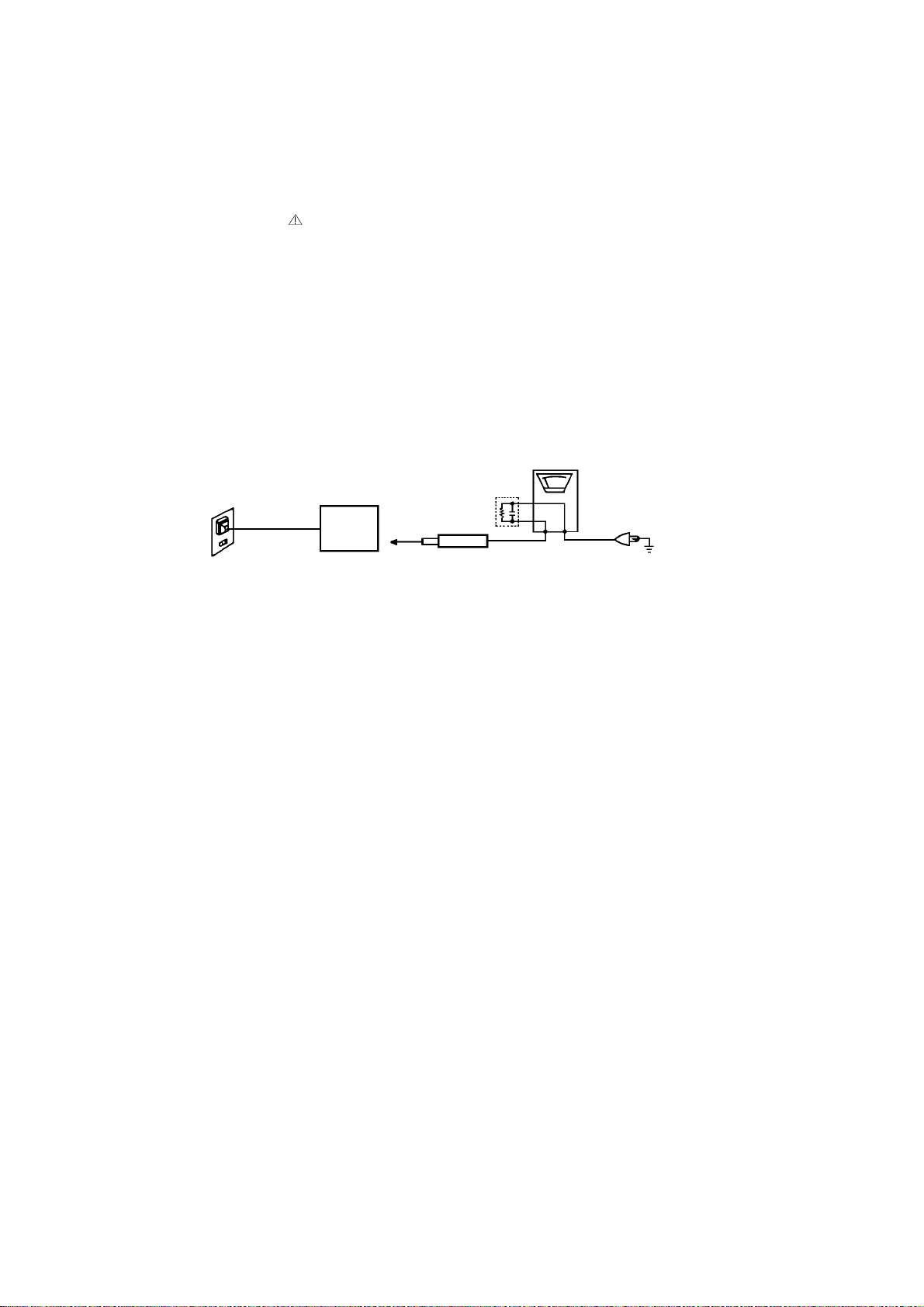
IMPORTANT SERVICE SAFETY INFORMATION
Safety precautions to be followed during servicing:
1.
Parts marked with an
are critical parts for safety. Replace only with the one described in the parts
list.
2.
Before returning the DVD product to the customer, make the appropriate leakage current check or
resistance measurements to ensure that exposed parts are properly insulated from the supply circuit.
A leakage current check is recommended for this unit. Plug the AC line cord directly into a 120V 60Hz AC
outlet (do not use an isolation transformer for this check). Use a leakage current tester (Fig. 1) or a
metering system which complies with Underwriters Laboratories (UL 1492P). Measure for current from all
exposed metal parts of the cabinet to a known earth ground: particularly, any exposed metal part having a
return path to the chassis. Any current measured must not exceed 0.5mA. Any measurement not within
the limits outlined above are indicative of a potential shock hazard and corrective action must be taken
before returning the unit to the customer.
(Reading should not be above 0.5mA)
Leakage Current Tester
KNOWN EARTH
GROUND
2-Blade polarized
type cord set
PRODUCT UNDER TEST
Test all exposed
metal surfaces
TEST PROBE
1.5K ohm
0.15 µF
Fig. 1 AC Leakage Test
A1-2
Page 22

IMPORTANT SAFEGUARDS
1) Read these instructions.
2) Keep these instructions.
3) Heed all warnings.
4) Follow all instructions.
5) Do not use this apparatus near water.
6) Clean only with dry cloth.
7) Do not block any ventilation openings. Install in accordance with the manufacturer's instructions.
8) Do not install near any heat sources such as radiators, heat registers, stoves, or other apparatus (including
amplifiers) that produce heat.
9) Do not defeat the safety purpose of the polarized or grounding-type plug. A polarized plug has two blades
with one wider than the other. A grounding type plug has two blades and a third grounding prong. The wide
blade or the third prong are provided for your safety. If the provided plug does not fit into your outlet,
consult an electrician for replacement of the obsolete outlet.
10) Protect the power cord from being walked on or pinched particularly at plugs, convenience receptacles, and
the point where they exit from the apparatus.
11) Only use attachments/accessories specified by the manufacturer.
12) Use only with the cart, stand, tripod, bracket, or table specified by the manufacturer, or sold with the apparatus. When a cart is used, use caution when
moving the cart/apparatus combination to avoid injury from tip-over.
13) Unplug this apparatus during lightning storms or when unused for long
periods of time.
14) Refer all servicing to qualified service personnel. Servicing is required when
the apparatus has been damaged in any way, such as power-supply cord or
plug is damaged, liquid has been spilled or objects have fallen into the
apparatus, the apparatus has been exposed to rain or moisture, does not operate normally, or has been
dropped.
15) Apparatus shall not be exposed to dripping or splashing and that no objects filled with liquids, such a vases,
shall be placed on the apparatus.
16) An outside antenna system should not be located in the vicinity of overhead power lines or other electric
light or power circuits, or where it can fall into such power lines or circuits. When installing an outside
antenna system, extreme care should be taken to keep from touching such power lines or circuits, as
contact with them might be fatal.
17) Do not overload wall outlets and extension cords, as this can result in a risk of fire or electric shock.
18) Do not push objects through any openings in this unit, as they may touch dangerous voltage points or short
out parts that could result in fire or electric shock. Never spill or spray any type of liquid into the unit.
PORTABLE CART WARNING
(symbol provided by RETAC)
S3126A
A1-3
Page 23
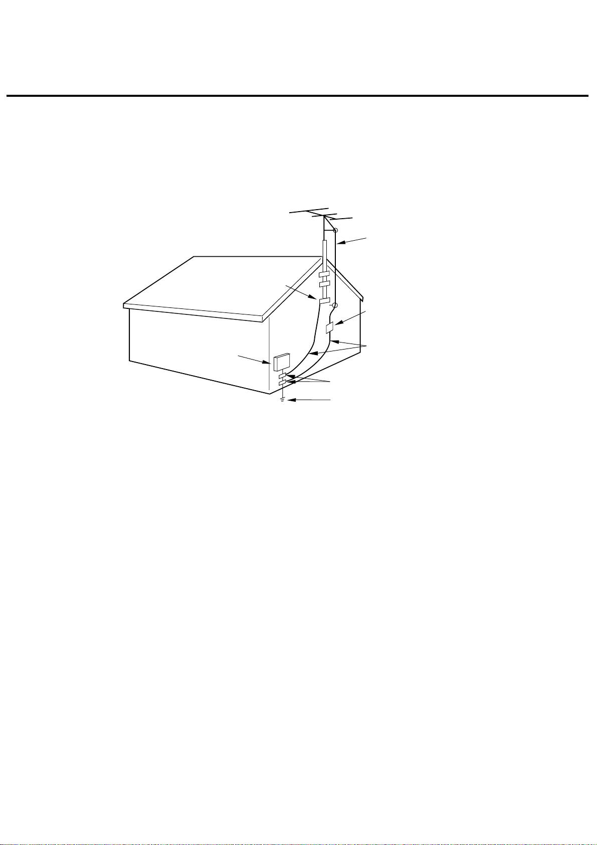
IMPORTANT SAFEGUARDS (CONTINUED)
19) If an outside antenna or cable system is connected to the unit, be sure the antenna or cable system is
grounded to provide some protection against voltage surges and built-up static charges, Section 810 of the
National Electrical Code, ANSI/NFPA 70, provides information with respect to proper grounding of the mast
and supporting structure, grounding of the lead-in wire to an antenna discharge unit, size of grounding
conductors, location of antenna discharge unit, connection to grounding electrodes, and requirements for
the grounding electrode.
EXAMPLE OF ANTENNA GROUNDING AS PER THE
NATIONAL ELECTRICAL CODE
ANTENNA LEAD
IN WIRE
GROUND
CLAMP
ANTENNA
DISCHARGE UNIT
(NEC SECTION 810-20)
ELECTRIC SERVICE
EQUIPMENT
GROUND CLAMPS
NEC-NATIONAL ELECTRICAL CODE
S2898A
20) When replacement parts are required, be sure the service technician uses replacement parts specified by
the manufacturer or those that have the same characteristics as the original part.
Unauthorized substitutions may result in fire, electric shock or other hazards.
21) Upon completion of any service or repairs to this unit, ask the service technician to perform safety checks to
determine that the unit is in proper operating condition.
22) Keep your fingers clear of the disc slot as it is closing. It may cause injury.
23) When you connect the product to other equipment, turn off the power and unplug all of the equipment from
the wall outlet. Failure to do so may cause an electric shock and serious personal injury. Read the owner's
manual of the other equipment carefully and follow the instructions when making any connections.
24) Reduce the volume to the minimum level before you turn on the product. Otherwise, sudden high volume
sound may cause hearing or speaker damage.
POWER SERVICE GROUNDING
ELECTRODE SYSTEM
(NEC ART 250, PART H)
GROUNDING CONDUCTORS
(NEC SECTION 810-21)
A1-4
Page 24

IMPORTANT SAFEGUARDS (CONTINUED)
25) Do not allow the product to output distorted sound for an extended period of time. It may cause speaker
overheating and fire.
26) When you use the headphones, keep the volume at a moderate level. If you use the headphones continuously with high volume sound, it may cause hearing damage.
27) Do not look into the opening of the disc slot or ventilation opening of the product to see the source of the
laser beam. It may cause eye damage.
28) Do not use a cracked, deformed, or repaired disc. These discs are easily broken and may cause serious
personal injury and product malfunction.
29) This reminder is provided to call the cable TV system installer’s attention to Article 820-40 of the NEC that
provides guidelines for proper grounding and, in particular, specifies that the cable ground shall be connected to the grounding system of the building, as close to the point of cable entry as practical.
CONDENSATION
Moisture will form in the operating section of the player if the player is brought from cool surroundings into a
warm room or if the temperature of the room rises suddenly. When this happens, player's performance will
be impaired.
To prevent this, let the player stand in its new surroundings for about an hour before switching it on, or
make sure that the room temperature rises gradually.
Condensation may also form during the summer if the player is exposed to the breeze from an air conditioner. In such cases, change the location of the player.
HOW TO HANDLE THE LCD PANEL
• Do not press hard or jolt the LCD panel. It may cause the LCD panel glass to break and injury may occur.
• If the LCD panel is broken, make absolutely sure that you do not touch the liquid in the panel. This may cause
skin inflammation.
If the liquid gets in your mouth, immediately gargle and consult with your doctor. Also, if the liquid gets in
your eyes or touches your skin, consult with your doctor after rinsing for at least 15 minutes or longer in clean
water.
A1-5
Page 25
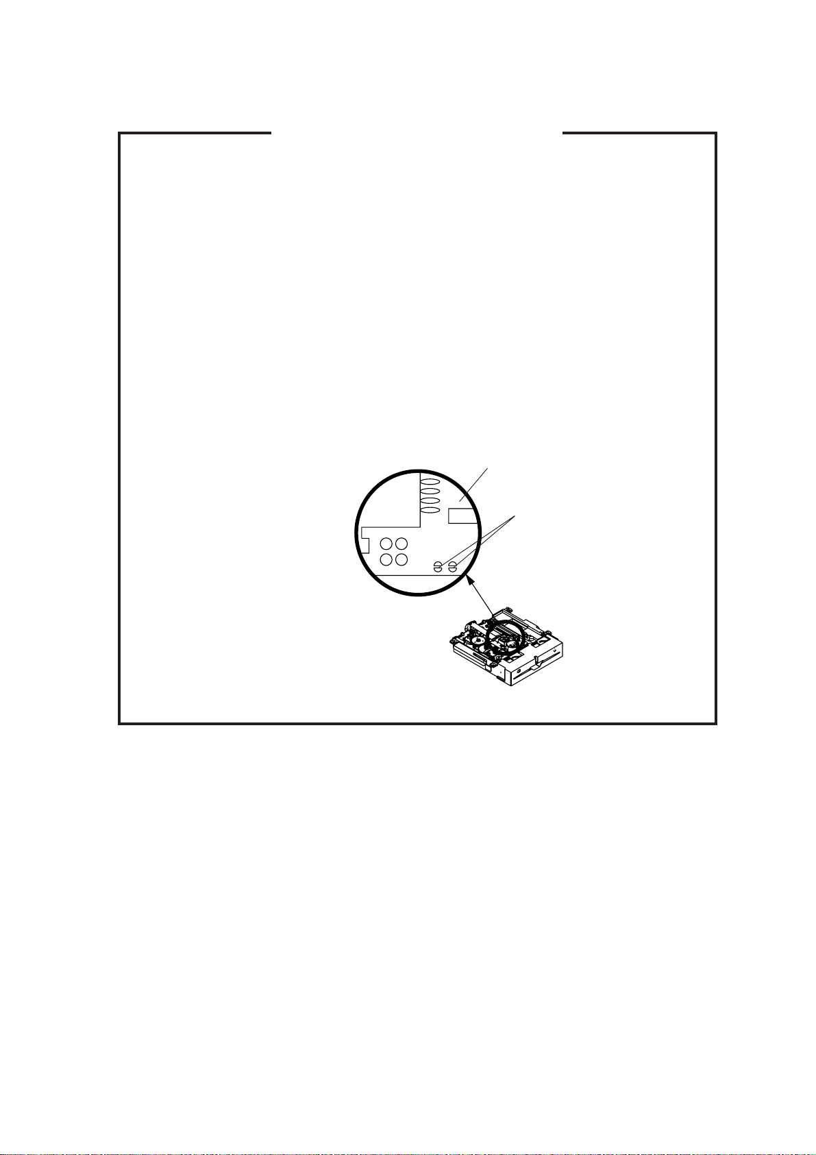
WHEN REPLACING DVD DECK
[ When removing the DVD Deck ]
Before removing Pick Up PCB and DVD PCB connector, the short circuit the position shown in Fig. 1
using a soldering iron. If you remove the DVD Deck with no soldering, the Laser may be damaged.
[ When installing the DVD Deck ]
Remove all the soldering on the short circuit position after the connection of Pick Up PCB and DVD
PCB connector.
NOTE
Before your operation, please read ÒPREPARATION OF SERVICINGÓ.
•
Use the Lead Free solder.
•
Manual soldering conditions
•
• Soldering temperature: 320 ± 20
• Soldering time: Within 3 seconds
• Soldering combination: Sn-3.0Ag-0.5Cu
When Soldering/Removing of solder, use the draw in equipment over the Pick Up Unit to keep the
•
Flux smoke away from it.
o
C
Pick Up PCB
Short circuit using a
soldering iron.
Fig. 1
A1-6
Page 26
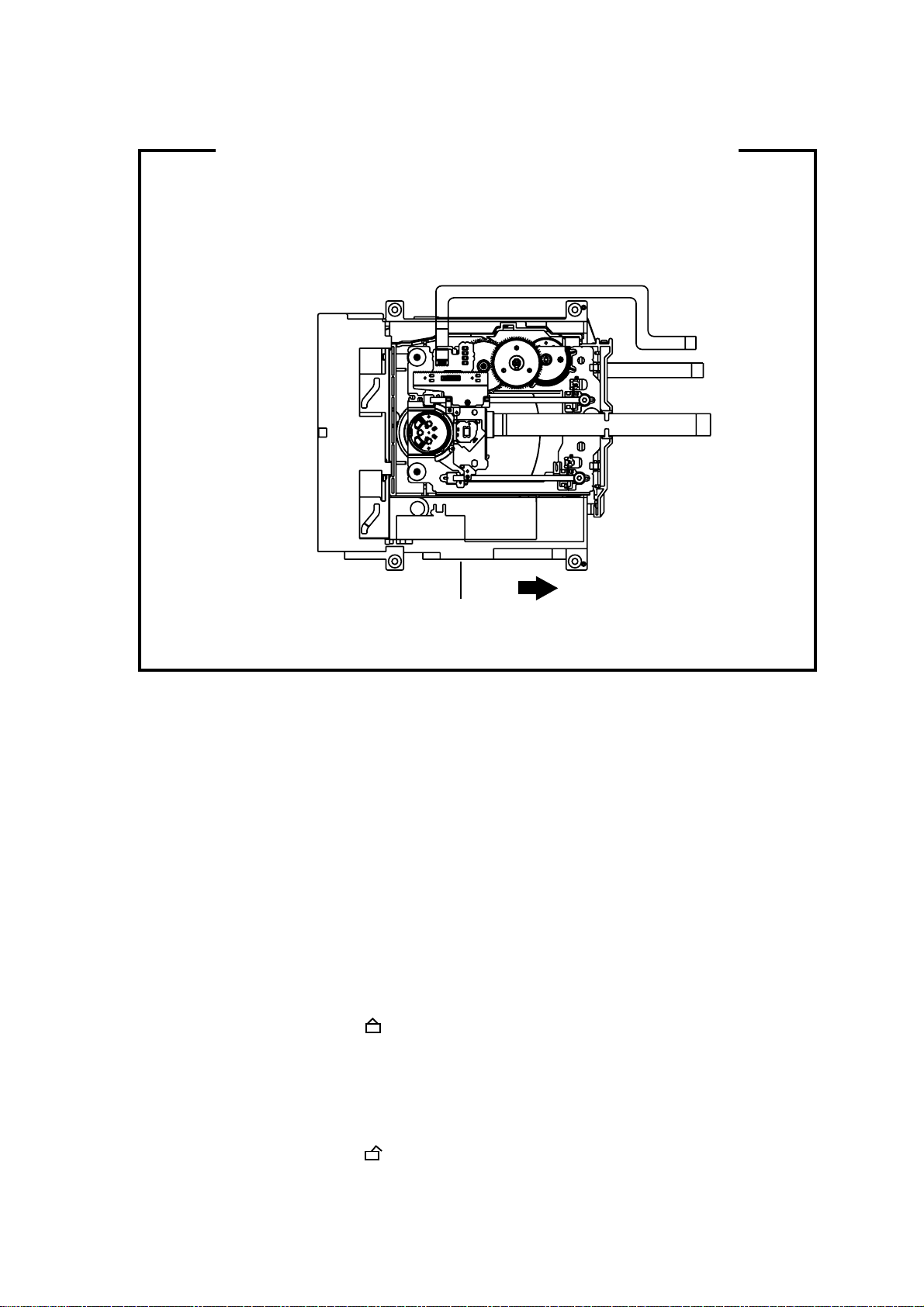
DISC REMOVAL METHOD AT NO POWER SUPPLY
1.
Remove the Back Cabinet and Angle Deck. (Refer to item 1 of the DISASSEMBLY INSTRUCTIONS.)
2.
Slide the Belt Loading toward the arrow direction by hand to release the lock. (Refer to Fig. 1)
3.
Take out the Disc from the DVD Deck. Be careful not to scratch on the Disc.
DVD Deck
Belt Loading
Fig. 1
PARENTAL CONTROL - RATING LEVEL
4 DIGIT PASSWORD CANCELLATION
If the stored 4 digit password in the Rating Level menu needs to be cancelled, please follow the steps below.
Turn Unit ON.
1.
Set the DVD to the Stop Mode.
2.
Check that ‘No disc’ is displayed on the screen.
3.
Press and hold the ‘STOP’ button on the front panel.
4.
Simultaneously press and hold the ‘7’ key on the remote control unit.
5.
Hold both keys for more than 2 seconds.
6.
The On Screen Display message ‘PASSWORD CLEAR’ will appear.
7.
The 4 digit password has now been cleared.
8.
TRAY LOCK
The disk cannot be taken out by setting the Tray Lock, please follow the steps below.
Turn Unit ON.
1.
Set the DVD to the Stop Mode.
2.
Press it in order of ‘SETUP’, ‘SUBTITLE’, ‘3’, ‘AUDIO’ and ‘0’ key of a remote control unit.
3.
The On Screen Display message ‘ ‘ will appear.
4.
The Tray Lock has now been set up.
5.
To unlock the Tray Lock, please follow the steps below.
Turn Unit ON.
1.
Set the DVD to the Stop Mode.
2.
Press it in order of ‘SETUP’, ‘SUBTITLE’, ‘3’, ‘AUDIO’ and ‘0’ key of a remote control unit.
3.
The On Screen Display message ‘ ‘ will appear.
4.
The Tray Lock has now been cleared.
5.
A1-7
Page 27

TABLE OF CONTENTS
ï GREEN PRODUCT PROCUREMENT
ï LEAD-FREE SOLDER
ï OWNER'S MANUAL
CAUTION.....................................................................................................................
IMPORTANT SERVICE SAFETY INFORMATION .....................................................
IMPORTANT SAFEGUARDS .....................................................................................
WHEN REPLACING DVD DECK ................................................................................
DISC REMOVAL METHOD AT NO POWER SUPPLY ..............................................
PARENTAL CONTROL - RATING LEVEL .................................................................
TRAY LOCK ................................................................................................................
TABLE OF CONTENTS ..............................................................................................
GENERAL SPECIFICATIONS ....................................................................................
DISASSEMBLY INSTRUCTIONS
1.REMOVAL OF MECHANICAL PARTS AND P.C. BOARDS ................................
2.REMOVAL OF DVD DECK PARTS ......................................................................
3.REMOVAL AND INSTALLATION OF FLAT PACKAGE IC ..................................
SERVICE MODE LIST ................................................................................................
SERVICING FIXTURES AND TOOLS ........................................................................
RE-WRITE FOR DVD FIRMWARE .............................................................................
WHEN REPLACING EEPROM (MEMORY) IC...........................................................
ELECTRICAL ADJUSTMENTS ..................................................................................
TROUBLESHOOTING GUIDE ....................................................................................
BLOCK DIAGRAMS
DVD..........................................................................................................................
ANALOG TUNER .....................................................................................................
AV SW/MICON/SOUND AMP..................................................................................
LVDS/TUNER/DIGITAL/POWER .............................................................................
PRINTED CIRCUIT BOARDS
DVD..........................................................................................................................
POWER....................................................................................................................
OPERATION/REMOCON ........................................................................................
BACK LIGHT/SW .....................................................................................................
DIGITAL ...................................................................................................................
SCHEMATIC DIAGRAMS
ASIC .........................................................................................................................
SDRAM.....................................................................................................................
FLASH......................................................................................................................
FRONT END ............................................................................................................
AV OUT....................................................................................................................
POWER1..................................................................................................................
LVDS........................................................................................................................
VIDEO AD ................................................................................................................
MICON .....................................................................................................................
AV SWITCH/JACK ...................................................................................................
SOUND AMP ...........................................................................................................
MPEG/MICON/DSP/RF_AMP..................................................................................
MEMORY .................................................................................................................
AUDIO/VIDEO..........................................................................................................
MOTOR DRIVE ........................................................................................................
REGULATOR...........................................................................................................
OPERATION/REMOCON ........................................................................................
POWER2..................................................................................................................
INVERTER ...............................................................................................................
SW ...........................................................................................................................
INTERCONNECTION DIAGRAM................................................................................
WAVEFORMS..........................................................................................................
MECHANICAL EXPLODED VIEWS ...........................................................................
DVD DECK EXPLODED VIEW ...................................................................................
MECHANICAL REPLACEMENT PARTS LIST ..........................................................
DVD DECK REPLACEMENT PARTS LIST................................................................
ELECTRICAL REPLACEMENT PARTS LIST ...........................................................
OPERATION MANUAL................................................................................................
A1-1
A1-2
A1-3~A1-5
A1-6
A1-7
A1-7
A1-7
A2-1
A3-1~A3-5
B1-1~B1-4
B2-1, B2-2
B3-1, B3-2
C-1
C-2
C-2
C-3
D-1~D-5
E-1~E-11
F-1, F-2
F-3, F-4
F-5, F-6
F-7, F-8
G-1, G-2
G-3~G-6
G-7~G-10
G-11, G-12
G-13~G-16
H-1, H-2
H-3, H-4
H-5, H-6
H-7, H-8
H-9, H-10
H-11, H-12
H-13, H-14
H-15, H-16
H-17, H-18
H-19, H-20
H-21, H-22
H-23, H-24
H-25, H-26
H-27, H-28
H-29, H-30
H-31, H-32
H-33, H-34
H-35, H-36
H-37, H-38
H-39, H-40
H-41, H-42
I-1~I-3
J1-1~J1-3
J2-1
K1-1, K1-2
K2-1
K3-1~K3-6
L1-1~L1-4
A2-1
Page 28

GENERAL SPECIFICATIONS
G-1 TV LCD LCD Size / Visual Size 15.0 inch / 380.0mmV
System LCD Type Color TFT LCD
Color System NTSC
Speaker 2 Speaker
Sound Output Max 1.0W + 1.0W
G-2 DVD System Color System NTSC
Disc
Disc Diameter 120 mm , 80 mm
Drive DSM-2
Search speed Fwd 4 step
Slow speed Fwd 1/7 -1/2 times
G-3 Tuning Broadcasting System Analog US System M
System Digital ATSC(8VSB)/QAM
Tuner and System 1Tuner
Receive CH Destination US(W/CABLE)
Intermediate Digital 44.00MHz
Frequency Analog Picture(FP) 45.75MHz
Preset CH No
Stereo/Dual TV Sound US-Stereo
Tuner Sound Muting Yes
G-4 Signal Video Signal Input Level 1 V p-p/75 ohm
RGB Signal Output Level -Audio Signal Input Level -8.0dBm/50k ohm
G-5 Power Power Source AC 120V, 60Hz
Power Consumption at AC 50W at 120V 60Hz
Protector Power Fuse Yes
G-6 Regulation Safety UL(UL6500_2nd)
G-7 Temperature Operation
Number of Pixels 1024(H) x 768(V)
View Range Left/Right 70/70 degree
Up/Down 65/60 degree
Position Front
Size 1.5 x 2.7 inch
Impedance 8 ohm
10%(Typical) ---
DVD, CD-DA, CD-R/RW, Video CD
DVD-R/RW (Video Format Only)
Actual 2-45 times (DVD)
4-40 times (CD)
Rev 4 step
Actual 2-45 times (DVD)
4-40 times (CD)
Actual --
Rev 1/7 -1/2 times
Actual --
CH Coverage 2~69, 4A, A-5~A-1, A~I, J~W, W+1~W+84
Sound(FS) 41.25MHz
FP-FS 4.50MHz
Output Level -S/N Ratio (Weighted) -Horizontal Resolution at DVD Mode --
--
Output Level -Digital Output Level 0.5 V p-p/75 ohm
S/N Ratio at DVD (Weighted) -Harmonic Distortion -Frequency Response : at DVD --
at Video CD --
at SVCD --
at CD --
DC --
at DC -Stand by (at AC Adapter) 1W at 120V 60Hz
Energy Star Yes
Per Year -- kWh/Year
Safety Circuit Yes
IC Protector(Micro Fuse) No
Radiation FCC
Laser DHHS
Storage
+o ~ +4
-2
o
o
o
~ +
A3-1
Page 29

GENERAL SPECIFICATIONS
G-8 Operating Humidity Less than 80% RH
G-9 Clock and Clock No
Timer Sleep Timer Max Time 120 Min
On Timer Program No
Off Timer Program No
Wake Up Timer No
Timer Back-up (at Power Off Mode) more than -- Min Sec
G-10 Remote Unit RC-LT
Control Glow in Dark Remocon Yes
Remocon Format TOSHIBA
Format TOSHIBA
Custom Code 40-BF h ,44-BB h ,45-BA h ,45-BC h
Power Source Voltage(D.C) 3V
Total Keys 49 Keys
Keys Power Yes
Step 10 Min
UM size x pcs UM-4 x 2 pcs
Eject Yes
Sleep Yes
TV/DVD Yes
1 Yes
2 Yes
3 Yes
4 Yes
5 Yes
6 Yes
7 Yes
8 Yes
9 Yes
0 Yes
100 / Jump / - Yes
Display Yes
Subtitle Yes
Audio Select Yes
Input Select / Zoom Yes
Mute Yes
CH Up Yes
CH Down Yes
Vol Up Yes
Vol Down Yes
Play Mode Yes
DVD Menu Yes
Up Yes
Down Yes
Left / Fav- Yes
Right / Fav+ Yes
Enter Yes
Menu / Setup Yes
Exit / Cancel Yes
Game Yes
Picture Size Yes
Pause Yes
Play Yes
Stop Yes
Skip+ / Closed Caption Yes
Skip- / CH Return Yes
Search+ Yes
Search- Yes
Slow+ Yes
Slow- Yes
Angle Yes
Maker Yes
Top Menu Yes
Return Yes
Closed Caption No
Repeat A-B Yes
Zoom/ Quick View No
Freeze frame No
A3-2
Page 30
GENERAL SPECIFICATIONS
(
)
)
)
)
)
)
)
)
G-11 Features Auto Shut Off Yes
(TV) Auto Search No
Power On Memory No
Comb Filter Yes
Game Position Yes
Auto Setup(Language/CH Program) Yes
Picture Setting Yes
Audio MTS Yes
Tuning CH Program Yes
Label CH Label No
Favorite CH Yes
V-Chip Yes
RRT Setup
Lock Hotel Lock No
OSD Language
Closed Caption
CC Advanced
Picture Size Yes
Picture Scroll
Cinema Mode Yes
Aspect
Backlight No
PFC(Power Factor circuit)
Freeze frame No
PIP/POP No
Direct Input Selection No
Game Position Yes
PC Monitor Input No
HDMI Input No
Component Input Yes
Mode(Picture Preference) Yes
Brightness , Contrast , Color Yes
Tint Yes
Sharpness Yes
Color Temperature Yes
Cable Clear Yes
Tone Control (Bass/Treble/Balance) Yes
Stable Sound Yes
Surround Yes
BBE No
SRS WOW (SRS 3D/Focus/Tru Bass) No
Valiable Audio Out No
TV/Cable Yes
ADD/ERASE Yes
Video Label No
Type USA Type
Channel Lock No
Video Lock No
Panel Lock No
×480i
720
720×480i(16:9
720×480p(4:3
720×480p(16:9
720×576i(4:3
720×576i(16:9
720×576p(4:3
720×576p(16:9
1280×720p
1920×1080i
4:3
3D
Yes
English
French
Spanish
Yes
Yes
Yes (60Hz)
Yes (60Hz)
Yes (60Hz)
Yes (60Hz)
Yes (60Hz)
Yes (60Hz)
No
No
No
No
No
No
No
A3-3
Page 31

GENERAL SPECIFICATIONS
Features Tray Lock Yes
(DVD) WMA Yes
JPEG Yes
Video CD Playback Yes
SVCD Playback
Overlay Graphics And Text No
Command List No
Entry Point Jump No
MP3 Playback Yes
Divx Playback Yes
DMF Support No
Digital Out (Dolby Digital) Yes
(MPEG) Yes
(PCM) Yes
(DTS) Yes
Down Mix Out (Dolby Digital) Yes
(DTS) No
3D Surround No
Closed Caption Yes
Screen Saver No
Audio DAC 192kHz / 24bit
G-12 Accessories Owner's Manual Language English
w/Guarantee Card Yes
Remote Control Unit Yes
Rod Antenna
Poles -Terminal --
Loop Antenna
Terminal --
U/V Mixer
DC Car Cord (Center+)
Guarantee Card
Warning Sheet
Circuit Diagram
Antenna Change Plug
Service Facility List
Important Safeguard
Dew/AHC Caution Sheet
Quick Set-up Sheet
Battery Yes
UM size x pcs UM-4 x 2 pcs
OEM Brand No
AC Adapter
AC Cord (for AC Adapter)
AV Cord (2Pin-1Pin)
Registration Card Yes
300 ohm to 75 ohm Antenna Adapter
Sheet Information (Return) Yes(USA version)
No
No
No
No
No
No
No
No
No
No
No
No
No
No
No
No
No
A3-4
Page 32

GENERAL SPECIFICATIONS
G-13 Interface Switch Side Power (Tact) Yes
Rear Main Power SW No
Indicator Power/Stand-By Yes (Green / Red)
Terminals Rear Video Input 2 RCA x 1
Side Video Input 1 RCA x 1
G-14 Set Size Approx. W x D x H (mm) 394 x 190 x 381.8
G-15 Weight Net (Approx.) 5.5kg (12.1 lbs)
G-16 Carton Master Carton No
Gift Box Material Single/White
Drop Test
Container Stuffing (40' container) 976
G-17 Material Cabinet Front PS 94V0 DECABROM
PCB Non-Halogen Demand No
G-18 Environment Environmental standard requirement (by buyer) Green procurement of TOSHIBA
Channel Up Yes
Channel Down Yes
Volume Up Yes
Volume Down Yes
Play Yes
Eject Yes
Skip+, Search+ No
Skip-, Search- No
Still/Pause No
Stop Yes
Main Power SW No
Input Select No
On Timer No
Audio Input 2 RCA x 2 (L/MONO, R)
S- Input 2 No
Video Output No
Audio Output No
Component Yes
Euro Scart(21Pin) No
PC Monitor Input No
DC Jack (Center +) No
VHF/UHF Antenna Input
AC Outlet No
Audio Input 1 RCA x 2 (L/MONO, R)
S- Input 1 Yes
Digital Audio Output Coaxial
Other Terminal Headphone
w/o Handle, Stand Approx. W x D x H (mm)
Net w/o Handle, Stand (Approx.) 4.7kg (10.3 lbs)
Gross (Approx.) 7.5kg (16.5 lbs)
Content --- Sets
Material --- / --Dimensions W x D x H(mm) --Description of Origin ---
W/Color Photo Label No
Dimensions W x D x H(mm) 495x275x470
Description of Origin Yes
Height (cm) 80
Rear PS 94V0 DECABROM
Jack Panel --
Eyelet Demand Yes
Pb-free Phase3 (Phase3A)
Measures for Whisker Yes
F Type
394 x 91 x 357.3
Natural Dropping At 2 Corner / 2 Edges / 3
Surfaces
Sets/40' container
A3-5
Page 33

DISASSEMBLY INSTRUCTIONS
1. REMOVAL OF MECHANICAL PARTS
AND P.C. BOARDS
1-1: HINGE ASS'Y (Refer to Fig. 1-1)
1.
Remove the 3 screws (1).
2.
Remove the Stand in the direction of arrow (A).
3.
Remove the 4 screws (2).
4.
Remove the Stand Angle in the direction of arrow (B).
5.
Remove the 4 screws (3).
6.
Remove the Hinge Ass'y in the direction of arrow (C).
(3)
(C)
Stand Angle
(3)
(2)
(2)
(3)
Fig. 1-1
(3)
(1)
(1)
(1)
Stand
(A)
(B)
Hinge Ass'y
1-2: BACK CABINET (Refer to Fig. 1-2)
1.2.Remove the 10 screws (1).
Remove the Back Cabinet in the direction of arrow.
1-3: ANGLE BACK (Refer to Fig. 1-3)
1.2.Remove the 3 screws (1).
Remove the Angle Back in the direction of arrow.
(1)
(1)
(1)
Angle Back
1-4: OPERATION PCB (Refer to Fig. 1-4)
1.
Disconnect the following connector: (CP2001).
2.
Remove the 3 screws (1).
3.
Remove the Panel Side in the direction of arrow (A).
4.
Remove the 3 screws (2).
5.
Remove the Operation PCB in the direction of arrow (B).
Operation PCB
(2)
(2)
(2
(1)
(B)
CP2001
(1)
(1)
Panel side
Fig. 1-3
(1)
(1)
(1)
(1)
(1)
(1)
Back Cabinet
(1)
(1)
(1)
(1)
(A)
Fig. 1-4
Fig. 1-2
B1-1
Page 34

DISASSEMBLY INSTRUCTIONS
1-5: ANGLE DVD ASS'Y (Refer to Fig. 1-5)1-5: ANGLE DVD ASS'Y (Refer to Fig. 1-5)
1-5: ANGLE DVD ASS'Y (Refer to Fig. 1-5)
1-5: ANGLE DVD ASS'Y (Refer to Fig. 1-5)1-5: ANGLE DVD ASS'Y (Refer to Fig. 1-5)
1.
Disconnect the following connectors:
(CP506 and CP701).
2.
Remove the 5 screws (1).
3.
Remove the Angle DVD Ass'y in the direction of arrow.
(1)
(1)
(1)
(1)
CP701
1-6: DVD DECK (Refer to Fig. 1-6)
1.
Short circuit the position shown in Fig. 1-6 using a
soldering iron. If you remove the DVD Deck with no
soldering, the Laser may be damaged.
2.
Remove the 4 screws (1).
3.
Disconnect the following connectors:
(CP2301, CP2302 and CP2303).
4.
Remove the DVD MT PCB in the direction of arrow (A).
5.
Remove the 4 screws (2).
6.
Remove the DVD Deck in the direction of arrow (B).
Angle DVD Ass'y
(1)
Angle DVD Ass'y
CP506
Fig. 1-5
NOTE
1.
Before your operation, please read "PREPARATION OF
SERVICING"
2.
Use the Lead Free solder.
3.
Manual soldering conditions
• Soldering temperature: 320 ± 20
o
C
• Soldering time: Within 3 seconds
• Soldering combination: Sn-3.0Ag-0.5Cu
When Soldering/Removing of solder, use the drawing
4.
equipment over the Pick Up Unit to keep the Flux smoke
away from it.
When installing the DVD Deck, remove all the soldering on
5.
the short circuit position after the connection of Pick Up
PCB and DVD MT PCB connector.
PLATE JACK-SIDE/SHIELD JACK-SIDE and PLATE
1-7:
JACK-1 (Refer to Fig. 1-7)
1.
Remove the 2 screws (1).
2.
Remove the 2 screws (2).
3.
Remove the Plate Jack-Side in the direction of arrow (A).
4.
Remove the screw (3).
5.
Remove the Shield Jack-Side in the direction of arrow (B).
6.
Remove the 2 screws (4).
7.
Remove the screw (5).
8.
Remove the Plate Jack-1 in the direction of arrow (C).
(2) (2)
(1)
(1)
Plate Jack-Side
(A)
(3)
Shield Jack-Side
(B)
(C)
(4)
(4)
(5)
Plate Jack-1
DVD MT PCB
CP2303
(1)
(A)
(1)
CP2302
(1)
(B)
(2)
(1)
CP2301
(2)
Pick Up PCB
Fig. 1-7
2
(2)
(2)
DVD Deck
Short circuit using a
soldering iron.
Fig. 1-6
B1-2
Page 35

DISASSEMBLY INSTRUCTIONS
1-8: DIGITAL PCB (Refer to Fig. 1-8)
1.
Disconnect the following connectors:
(CP106, CP507 and CP2407).
2.
Remove the 7 screws 1.
3.
Remove the Shield Digital and Digital PCB in the direction
of arrow.
1
1
1
1
1
Shield Digital
CP106
Digital PCB
CP2407
CP507
BACK LIGHT PCB (Refer to Fig. 1-10)
1-10:
1.
Disconnect the following connectors:
(CP7001, CP7002, CP7003 and CP7004).
2.
Remove the 4 screws 1.
3.
Remove the Shield Inverter and Back Light PCB in the
4.
direction of arrow.
1
1
1
1
Shield Inverter
CP7001
CP7003
CP7002
CP7004
Back Light PCB
Fig. 1-10
1-9: POWER PCB (Refer to Fig. 1-9)
1.
Disconnect the following connector: (CP505)
2.
Remove the screw 1.
3.
Remove the Plate Jack-2 in the direction of arrow (A).
4.
Remove the 3 screws 2.
5.
Remove the Power PCB in the direction of arrow (B).
2
2
2
Power PCB
CP505
(A)
Plate Jack-2
Fig. 1-8
1
Fig. 1-9
B1-3
Page 36

DISASSEMBLY INSTRUCTIONS
REMOCON PCB/COVER LCD/LCD PANEL
1-11:
(Refer to Fig. 1-11)
1.
Remove the 2 screws 1.
2.
Remove the Remocon PCB in the direction of arrow (A).
3.
Remove the 2 screws 2.
4.
Remove the Angle Hinge in the direction of arrow (B).
5.
Remove the 3 screws 3.
6.
Remove the Cover LCD in the direction of arrow (C).
7.
Remove the 4 screws 4.
8.
Remove the LCD Panel in the direction of arrow (D).
2
2
3
4
3
4
(D)
(B)
4
Angle Hinge
3
4
Cover LCD
(C)
LCD Panel
1
1
Remocon PCB
(A)
Fig. 1-11
B1-4
Page 37

DISASSEMBLY INSTRUCTIONS
2. REMOVAL OF DVD DECK PARTS
NOTE
1. Disassemble only the DVD DECK PARTS parts listed
here. Minute adjustments are needed if the disassembly
is done. If the repair is needed except listed parts, replace
the DVD MECHA ASS'Y.
2-1: TRAVERSE ASS'Y (Refer to Fig. 2-1-A)
Remove the 3 screws (1).
1.
Unlock the 2 supports (2).
2.
Remove the Insulator (R) from the Loader Sub Ass'y.
3.
Remove the Traverse Ass'y.
4.
(2)
Loader Sub Ass'y
Traverse Ass'y
• Screw Torque: 2.0 ± 0.3kgf•cm
(1)
(1)
(2)
Insulator (R)
(1)
Fig. 2-1-A
Check Hook
Check Hook
Loader Ass'y (Top Side)
Check Hook
Fig. 2-1-D
2-2:
SWITCH PCB ASS'Y/GEAR MIDDLE/GEAR FEED/RACK
FEED ASS'Y/FEED MOTOR (Refer to Fig. 2-2-A)
Remove the Insulator (F).
1.
Remove the Insulator (R).
2.
Unlock the support (1).
3.
Remove the Gear Middle.
4.
Remove the screw (2).
5.
Remove the Rack Feed Ass'y.
6.
Remove the screw (3).
7.
Remove the Switch PCB Ass'y.
8.
Remove the screw (4).
9.
Remove the Gear Feed.
10.
Remove the 2 screws (5).
11.
Remove the Feed Motor.
12.
Remove the Gear Motor.
13.
Feed Motor
NOTE
In case of the Traverse Ass'y installation, hook the wire
1.
on the Loader Ass'y as shown Fig. 2-2-B to Fig. 2-2-D.
Loader Ass'y (Bottom Side)
Check Lock Check Lock
Check Hook
80 ± 5mm
Loader Ass'y
Fig. 2-1-B
Check Hook
Fig. 2-1-C
Traverse Ass'y
Insulator (F)
Insulator (F)
Rack Feed Ass'y
• Screw Torque: 1.3 ± 0.3kgf•cm (Screw 2)
• Screw Torque: 3.0 ± 0.3kgf•cm (Screw 3)
• Screw Torque: 1.0 ± 0.3kgf•cm (Screw 4, 5)
Gear Motor
(1)
(2)
(3)
Insulator (R)
(5)
(5)
Gear Feed
(4)
Gear Middle
Switch PCB Ass'y
Fig. 2-2-A
B2-1
Page 38

DISASSEMBLY INSTRUCTIONS
NOTE
1.
When installing the Rack Feed Ass'y, push both ends to
align the teeth as shown Fig. 2-2-B. Then install it.
2.
In case of the Gear Motor installation, check if the value
of the Fig. 2-2-C is correct.
3.
When installing the wire of the Switch PCB Ass'y, install it
correctly as Fig. 2-2-D.
Manual soldering conditions
¥ Soldering temperature: 320 ± 20
o
C
¥ Soldering time: Within 3 seconds
¥ Soldering combination: Sn-3.0Ag-0.5Cu
After the assembly of the Traverse Ass'y, hook the wire
4.
on the Traverse Ass'y as shown Fig. 2-2-E.
Rack Feed Ass'y
Push
[OK] [NG]
Push
Fig. 2-2-B
Check Hook
• Loosen the wire in the direction of the arrow.
Traverse Ass'y
Check Hook
Check Hook
Check Hook
Fig. 2-2-E
2-3: FFC WIRE HANDLING
1.
When installing the FFC, fold it correctly and install it as
shown from Fig. 2-3-A to Fig. 2-3-B.
NOTE
Do not make the folding lines except the specified
1.
positions for the FFC.
[ 24 pin FFC ]
Fold it by 90
To Pick Up PCB
Printing Surface
20 ± 1mm
Gear Motor
Feed Motor
~ SPINDLE MOTOR ~
Safety surface for pressing
of the insert.
Switch PCB Ass'y
YELLOW (2)
GREEN (1)
8.0 ± 0.2mm
Fig. 2-2-C
~ FEED MOTOR ~
WHITE (4)
BROWN (3)
¥ Install wire from (1) to (4) in order.
Fig. 2-2-D
[ 6 pin FFC ]
30 ± 1mm
Fig. 2-3-A
40 ± 1mm
Fold
Printing Surface
Fig. 2-3-B
B2-2
Page 39

DISASSEMBLY INSTRUCTIONS
3. REMOVAL AND INSTALLATION OF FLAT
PACKAGE IC
REMOVAL
1. Put the Masking Tape (cotton tape) around the Flat
Package IC to protect other parts from any damage.
(Refer to Fig. 3-1.)
NOTE
Masking is carried out on all the parts located within
10 mm distance from IC leads.
Masking Tape
(Cotton Tape)
2. Heat the IC leads using a blower type IC desoldering
machine. (Refer to Fig. 3-2.)
NOTE
Do not add the rotating and the back and forth directions force on the IC, until IC can move back and forth
easily after desoldering the IC leads completely.
IC
Fig. 3-1
Blower type IC
desoldering machine
3. When IC starts moving back and forth easily after
desoldering completely, pickup the corner of the IC using
a tweezers and remove the IC by moving with the IC
desoldering machine. (Refer to Fig. 3-3.)
NOTE
Some ICs on the PCB are affixed with glue, so be
careful not to break or damage the foil of each IC
leads or solder lands under the IC when removing it.
Blower type IC
desoldering machine
Tweezers
IC
4.5.Peel off the Masking Tape.
Absorb the solder left on the pattern using the Braided
Shield Wire. (Refer to Fig. 3-4.)
NOTE
Do not move the Braided Shield Wire in the vertical
direction towards the IC pattern.
Fig. 3-3
Braided Shield Wire
Soldering Iron
IC
Fig. 3-2
IC pattern
Fig. 3-4
B3-1
Page 40

DISASSEMBLY INSTRUCTIONS
INSTALLATION
1. Take care of the polarity of new IC and then install the
new IC fitting on the printed circuit pattern. Then solder
each lead on the diagonal positions of IC temporarily.
(Refer to Fig. 3-5.)
Soldering Iron
Solder temporarily
Solder temporarily
Fig. 3-5
2. Supply the solder from the upper position of IC leads
sliding to the lower position of the IC leads.
(Refer to Fig. 3-6.)
4. When bridge-soldering between terminals and/or the
soldering amount are not enough, resolder using a Thintip Soldering Iron. (Refer to Fig. 3-8.)
IC
Thin-tip Soldering Iron
Fig. 3-8
5. Finally, confirm the soldering status on four sides of the
IC using a magnifying glass.
Confirm that no abnormality is found on the soldering
position and installation position of the parts around the
IC. If some abnormality is found, correct by resoldering.
NOTE
When the IC leads are bent during soldering and/or
repairing, do not repair the bending of leads. If the
bending of leads are repaired, the pattern may be
damaged. So, be always sure to replace the IC in this
case.
Solder
IC
Supply soldering
from upper position
to lower position
Soldering Iron
3. Absorb the solder left on the lead using the Braided
Shield Wire. (Refer to Fig. 3-7.)
NOTE
Do not absorb the solder to excess.
Soldering Iron
IC
Braided Shield Wire
Fig. 3-6
Fig. 3-7
B3-2
Page 41

SER VICE MODE LIST
This unit provided with the following SERVICE MODES so you can repair, examine and adjust easily.
To enter to the SERVICE MODE function, press and hold both buttons simultaneously on the main unit and on the remote control
for more than a the standard time in the appropriate condition. (See below chart.)
Set
Condition
TV mode
TV mode
DVD mode
(No disc)
DVD mode
(No disc)
TV mode
TV mode
ALL mode
DVD mode
(No disc)
Set Key Operations
VOL. DOWN
(Minimum)
VOL. DOWN
(Minimum)
VOL. DOWN
(Minimum)
VOL. DOWN
(Minimum)
VOL. DOWN
(Minimum)
VOL. DOWN
(Minimum)
VOL. DOWN
(Minimum)
STOP 1 2 sec.
Remocon
Key
0 2 sec.
1 2 sec.
4 2 sec.
5 2 sec.
6 2 sec.
8
9 2 sec.
Standard
Time
2 sec.
Releasing of V-CHIP PASSWORD.
Initialization of factory TV data.
If you set factory initialization, the memories are reset such as
NOTE:
the channel setting, and the POWER ON total hours.
Initialization of factory DVD data.
DVD Write mode.
Refer to the “RE-WRITE FOR DVD FIRMWARE”.
POWER ON total hours are displayed on the screen.
Can be checked of the INITIAL DATA of MEMORY IC.
Refer to the "WHEN REPLACING EEPROM (MEMORY) IC".
Check of the SUM DATA and MICON VERSION on the screen.
Refer to the "WHEN REPLACING EEPROM (MEMORY) IC".
Display of the Adjustment MENU on the screen.
Refer to the "ELECTRICAL ADJUSTMENT" (On-Screen Display
Adjustment).
Region setting.
DVD
Refer to the “RE-WRITE FOR DVD FIRMWARE”.
DVD mode
(No disc)
Press the following remocon keys
continuously.
SETUP SUBTITLE 3
AUDIO 0
STOP 7 2 sec.
Method
Releasing of PARENTAL LOCK.
Refer to the “PARENTAL CONTROL - RATING LEVEL”.
The disk cannot be taken out.
Refer to the “TRAY LOCK”.
C-1
Page 42

SERVICING FIXTURES AND TOOLS
JG176 Up-Date Disc
Ref. No.
JG176
Part No.
APJG176117
Parts Name
Up-Date Disc
Up-Date of the Firmware
Remarks
RE-WRITE FOR DVD FIRMWARE
Turn on the power, and set the DVD mode.
1.
Confirm that the “No Disc” will be appeared on the screen.
2.
Press both VOL. DOWN button on the set and Channel button (5) on the remote control for more than 2 seconds.
3.
Press VOL. UP/DOWN button on the unit to check if all the keys on the unit do not function.
4.
NOTE: To check if DVD Write mode is set.
When inserting Up-Date Disc at Non DVD Write mode, the read error will happen.
Insert the Up-Date Disc. (Refer to SERVICING FIXTURE AND TOOLS)
5.
Automatic read will start and "Firmware upgrade Please Wait" will be displayed on the screen.
6.
At this time, the horizontal noise lines may appear. But no problem.
NOTE: Do not turn off the unit on the way or operate the keys on the unit and remocon.
Up-Date error will happen and can not be done with the Up-Date of Up-Date Disc.
After the Up-Date, Logo screen will appear.
7.
Unplug the AC cord, then plug it in.
8.
After the write, set to the initializing of shipping.
Turn on the power, and set the DVD mode.
9.
Press both VOL. DOWN button on the set and Channel button (4) on the remote control for more than 2 seconds.
10.
The "INITIALIZE 5 ---> COMPLETE" will appear on the screen.
Then unplug the AC cord, and plug it in.
11.
CHECK FOR THE FIRMWARE VERSION
Turn on the power, and set the DVD mode.
12.
Press both Channel button (1) on the remote control and the STOP button on the set for more than 2 seconds.
13.
Firmware version will be displayed on the top left of the screen.
No Disc
Turn off the power
14.
AAGJA6B01A
When the changed version displays, the Re-write will be completed.
A A G J A 6 B 0 1 A
Fixed
Release date (Example: 2006.11.01)
Released times on the same date
A = October
B = November
C = December
C-2
Page 43

WHEN REPLACING EEPROM (MEMORY) IC
CONFIRMATION OF CHECK SUM, POWER ON TOTAL HOURS AND MICON VERSION
Initial total of MEMORY IC, POWER ON total hours and MICON VERSIONcan be checked on the screen. Total hours are
displayed in 16 system of notation.
NOTE:
1.
2.
3.
4.
CONFIRMATION OF INITIAL DATA
If a service repair is undertaken where it has been required to change the MEMORY IC, the following steps should be taken to
ensure correct data settings while making reference to INITIAL SETTING TABLE (Attached "INITIAL DATA").
1.
2.
3.
If you set a factory initialization, the total hours is reset to "0".
Please refer to "CONFIRMATION OF INITIAL DATA" when SUM DATA is not corresponding.
Turn on the POWER, and set to the TV mode.
Set the VOLUME to minimum.
Press both VOL. DOWN button on the set and Channel
button (8) on the remote control for more than 2 seconds.
After the confirmation of each check sum, turn off the
HCS CHK SUM : 05E4
HRM CHK SUM : A38F
Initial setting data check sum.
Rom correction data check sum.
power.
POWER ON total hours.
= (16 x 16 x 16 x thousands digit value)
+ (16 x 16 x hundreds digit value)
+ (16 x tens digit value)
+ (ones digit value)
MICON Version
Digital TV MICON Fimware
LCD PWR ON : 0000
OEC6088A_037T
DTV CA00B6 Z051
FIG. 1
Turn on the POWER, and set to the TV mode.
Set the VOLUME to minimum.
Press both VOL. DOWN button on the set and Channel button (6) on the remote control for more than 2 seconds.
ADDRESS and DATA should appear as FIG 1.
ADDRESS DATA
HCS 00 0D
HRM 0600 00
OEC6088A_037
DTV CA00B6 Z051
FIG. 1
ADDRESS is now selected and should "blink". Using the UP/DOWN buton on the remote, step through the ADDRESS until
4.
Press RIGHT/LEFT button to select DATA. When DATA is selected, it will "blink".
Again, step through the DATA using UP/DOWN button until required DATA value has been selected.
5.
Pressing RIGHT/LEFT button will take you back to ADDRESS for further selection if necessary.
6.
Repeat steps 4 to 6 until all data has been checked.
7.
When satisfied correct DATA has been entered, turn POWER off (return to STANDBY MODE) to finish DATA input.
8.
After the data input, set to the initializing of shipping.
Turn POWER on.
9.
Press both VOL. DOWN button on the set and Channel button (1) on the remote control for more than 2 seconds.
10.
After the finishing of the initializing of shipping, the unit will turn off automatically.
11.
The unit will now have the correct DATA for the new MEMORY IC.
C-3
Page 44

INITIAL SETTING TABLE (15DLV77
)
A
INIT 0123456789
BCDEF
0000 0D 00 36 03 00 03 01 20 00 00 74 82 00 00 00 33
0010 05 00 00 00 00 00 00 00 03 00 25 28 FF FF FF FF
0020 FF FF FF FF FF FF FF FF FF FF FF FF FF FF FF FF
0030 00 00 00 10 FF FF FF FF FF FF FF FF FF FF FF FF
0040 FF FF FF FF FF FF FF FF FF FF FF FF FF FF FF FF
0050 FF FF FF FF FF FF FF FF FF FF FF FF FF FF FF FF
0060 FF FF FF FF FF FF FF FF FF FF FF FF FF FF FF FF
0070 FF FF FF FF FF FF FF FF FF FF FF FF FF FF FF FF
0080 FF FF FF FF FF FF FF FF FF FF FF FF FF FF FF FF
0090 FF FF FF FF FF FF FF FF FF FF FF FF FF FF FF FF
00A0 FF FF FF FF FF FF FF FF FF FF FF FF FF FF FF FF
00B0 FF FF FF FF FF FF FF FF FF FF FF FF FF FF FF FF
00C0 FF FF FF FF FF FF FF FF FF FF FF FF FF FF FF FF
00D0 FF FF FF FF FF FF FF FF FF FF FF FF FF FF FF FF
00E0 FF FF FF FF FF FF FF FF FF FF FF FF FF FF FF FF
00F0 FF FF FF FF FF FF FF FF FF FF FF FF FF FF FF FF
0100 FF FF FF FF FF FF FF FF FF FF FF FF FF FF FF FF
0110 FF FF FF FF FF FF FF FF FF FF FF FF FF FF FF FF
0120 FF FF FF FF FF FF FF FF FF FF FF FF FF FF FF FF
0130 FF FF FF FF FF FF FF FF FF FF FF FF FF FF FF FF
0140 FF FF FF FF FF FF FF FF FF FF FF FF FF FF FF FF
0150 FF FF FF FF FF FF FF FF FF FF FF FF FF FF FF FF
0160 FF FF FF FF FF FF FF FF FF FF FF FF FF FF FF FF
0170 FF FF FF FF FF FF FF FF FF FF FF FF FF FF FF FF
0180 FF FF FF FF FF FF FF FF FF FF FF FF FF FF FF FF
0190 FF FF FF FF FF FF FF FF FF FF FF FF FF FF FF FF
01A0 FF FF FF FF FF FF FF FF FF FF FF FF FF FF FF FF
01B0 FF FF FF FF FF FF FF FF FF FF FF FF FF FF FF FF
01C0 FF FF FF FF FF FF FF FF FF FF FF FF FF FF FF FF
01D0 FF FF FF FF FF FF FF FF FF FF FF FF FF FF FF FF
01E0 FF FF FF FF FF FF FF FF FF FF FF FF FF FF FF FF
01F0 FF FF FF FF FF FF FF FF FF FF FF FF FF FF FF FF
0200 00 00 00 40 FF FF FF FF FF FF FF FF FF FF FF FF
0210 FF FF FF FF FF FF FF FF FF FF FF FF FF FF FF FF
0220 FF FF FF FF FF FF FF FF FF FF FF FF FF FF FF FF
0230 FF FF FF FF FF FF FF FF FF FF FF FF FF FF FF FF
0240 FF FF FF FF FF FF FF FF FF FF FF FF FF FF FF FF
0250 FF FF FF FF FF FF FF FF FF FF FF FF FF FF FF FF
0260 FF FF FF FF FF FF FF FF FF FF FF FF FF FF FF FF
0270 FF FF FF FF FF FF FF FF FF FF FF FF FF FF FF FF
0280 FF FF FF FF FF FF FF FF FF FF FF FF FF FF FF FF
0290 FF FF FF FF FF FF FF FF FF FF FF FF FF FF FF FF
02A0 FF FF FF FF FF FF FF FF FF FF FF FF FF FF FF FF
02B0 FF FF FF FF FF FF FF FF FF FF FF FF FF FF FF FF
02C0 FF FF FF FF FF FF FF FF FF FF FF FF FF FF FF FF
02D0 FF FF FF FF FF FF FF FF FF FF FF FF FF FF FF FF
02E0 FF FF FF FF FF FF FF FF FF FF FF FF FF FF FF FF
02F0 FF FF FF FF FF FF FF FF FF FF FF FF FF FF FF FF
0300 FF FF FF FF FF FF FF FF FF FF FF FF FF FF FF FF
0310 FF FF FF FF FF FF FF FF FF FF FF FF FF FF FF FF
0320 FF FF FF FF FF FF FF FF FF FF FF FF FF FF FF FF
0330 FF FF FF FF FF FF FF FF FF FF FF FF FF FF FF FF
0340 FF FF FF FF FF FF FF FF FF FF FF FF FF FF FF FF
0350 FF FF FF FF FF FF FF FF FF FF FF FF FF FF FF FF
0360 FF FF FF FF FF FF FF FF FF FF FF FF FF FF FF FF
0370 FF FF FF FF FF FF FF FF FF FF FF FF FF FF FF FF
0380 FF FF FF FF FF FF FF FF FF FF FF FF FF FF FF FF
0390 FF FF FF FF FF FF FF FF FF FF FF FF FF FF FF FF
Page 45

03A0 FF FF FF FF FF FF FF FF FF FF FF FF FF FF FF FF
A
AEA
A
A9A
03B0 FF FF FF FF FF FF FF FF FF FF FF FF FF FF FF FF
03C0 FF FF FF FF FF FF FF FF FF FF FF FF FF FF FF FF
03D0 FF FF FF FF FF FF FF FF FF FF FF FF FF FF FF FF
03E0 FF FF FF FF FF FF FF FF FF FF FF FF FF FF FF FF
03F0 FF FF FF FF FF FF FF FF FF FF FF FF FF FF FF FF
0400 03 01 20 00 09 00 0C 00 0C 00 00 00 A1 00 A1 00
0410 A4 01 0C 00 0C 00 00 00 A1 00 A1 00 A4 01 00 00
0420 0C 00 0C 00 00 00 00 00 00 00 00 00 00 00 40 00
0430 00 40 00 0F 8F 87 00 00 00 00 00 00 00 19 32 19
0440 19 19 00 00 19 19 19 19 19 00 00 19 32 19 19 19
0450 00 00 19 32 19 19 19 00 00 19 32 19 19 19 00 00
0460 19 32 19 19 19 00 01 00 19 19 19 00 00 00 00 00
0470 00 00 00 01 14 14 01 00 00 00 00 00 00 00 00 00
0480 19 32 19 19 19 19 19 19 19 01 01 19 19 19 00 00
0490 00 00 00 00 00 00 00 00 00 00 00 00 00 00 00 00
04A0 00 00 00 00 00 00 00 00 00 00 00 00 00 00 00 00
04B0 00 00 00 00 00 00 00 00 00 00 00 00 00 00 00 00
04C0 00 00 00 00 00 00 00 00 00 00 00 00 00 00 00 00
04D0 00 00 00 00 00 00 00 00 00 00 00 00 00 00 00 00
04E0 00 00 00 00 00 00 00 00 00 00 00 00 00 00 00 00
04F0 00 00 00 00 00 00 00 00 00 00 00 00 00 00 00 00
0500 00 00 00 00 00 00 00 00 00 00 00 00 00 00 00 00
0510 00 00 00 00 00 00 00 00 00 00 00 00 3E 00 3E 00
0520 01 00 C1 00 C1 00 C4 01 01 28 FF FF FF FF FF FF
0530 FF FF FF FF FF FF FF FF FF FF FF FF FF FF FF FF
0540 FF FF FF FF FF FF FF FF FF FF FF FF FF FF FF FF
0550 FF FF FF FF FF FF FF FF FF FF FF FF FF FF FF FF
0560 FF FF FF FF FF FF FF FF FF FF FF FF FF FF FF FF
0570 FF FF FF FF FF FF FF FF FF FF FF FF FF FF FF FF
0580 FF FF FF FF FF FF FF FF FF FF FF FF FF FF FF FF
0590 FF FF FF FF FF FF FF FF FF FF FF FF FF FF FF FF
05A0 FF FF FF FF FF FF FF FF FF FF FF FF FF FF FF FF
05B0 FF FF FF FF FF FF FF FF FF FF FF FF FF FF FF FF
05C0 FF FF FF FF FF FF FF FF FF FF FF FF FF FF FF FF
05D0 FF FF FF FF FF FF FF FF FF FF FF FF FF FF FF FF
05E0 FF FF FF FF FF FF FF FF FF FF FF FF FF FF FF FF
05F0 FF FF FF FF FF FF FF FF FF FF FF FF FF FF FF FF
0600 00 00 01 01 00 00 00 35 01 00 00 01 01 01 00 01
0610 00 00 00 01 00 00 00 00 00 01 00 00 19 32 19 19
0620 19 00 01 FF 01 28 19 00 00 00 FF FF FF FF FF FF
0630 70 A0 B4 C8 D0 D4 D8 D
0640 E7 E9 E9 E
0650 F
FB FB FC FC FD FD FE FF FF FF FF FF FF FF FF
EB EC ED EF F0 F1 F2 F5 F7 F8 F9
DC DD E0 E1 E2 E3 E5 E6
0660 FF FF FF FF FF FF FF FF FF FF FF FF FF FF FF FF
0670 06 04 06 04 01 00 00 19 32 19 19 1B 28 19 19 20
0680 19 19 19 FF FF FF FF FF FF FF FF FF FF FF FF FF
0690 FF FF FF FF FF FF FF FF FF FF FF FF FF FF FF FF
06A0 FF FF FF FF FF FF FF FF FF FF FF FF FF FF FF FF
06B0 FF FF FF FF FF FF FF FF FF FF FF FF FF FF FF FF
06C0 FF FF FF FF FF FF FF FF FF FF FF FF FF FF FF FF
06D0 FF FF FF FF FF FF FF FF FF FF FF FF FF FF FF FF
06E0 FF FF FF FF FF FF FF FF FF FF FF FF FF FF FF FF
06F0 FF FF FF FF FF FF FF FF FF FF FF FF FF FF FF FF
0700 00 00 04 00 00 00 03 00 20 20 00 00 10 10 00 00
0710 04 00 00 60 02 40 20 20 00 00 0C 0C 00 00 04 00
0720 00 00 03 00 9
00 00 10 10 00 00 04 00 00 00
0730 03 00 20 20 00 00 10 10 00 00 04 00 00 00 03 00
0740 20 20 00 00 10 10 00 00 04 00 00 00 03 00 20 20
0750 00 00 10 10 00 00 04 00 00 60 02 40 20 20 00 00
Page 46

0760 0C 0C 00 00 04 00 00 00 03 00 9A9A00 00 10 10
A9A
A9A
A
A
A
A
A
A
A
A
A
A
A
A
A9A
A9A
A9A
A9A
A9A
A
A
A
A
0770 00 00 04 00 00 00 03 00 20 20 00 00 10 10 00 00
0780 04 00 00 00 03 00 20 20 00 00 10 10 00 00 04 00
0790 00 00 03 00 20 20 00 00 10 10 00 00 04 00 00 60
07A0 02 40 20 20 00 00 0C 0C 00 00 04 00 00 00 03 00
07B0 9
00 00 10 10 00 00 04 00 00 00 03 00 20 20
07C0 00 00 10 10 00 00 04 00 00 60 02 40 20 20 00 00
07D0 0C 0C 00 00 04 00 00 00 03 00 9
07E0 00 00 04 00 00 00 03 00 1
07F0 04 00 00 60 02 40 1
28 00 00 0A0E 00 00 04 00
28 00 00 0E 12 00 00
00 00 10 10
0800 00 00 03 00 92 A6 00 00 0E 12 00 00 04 00 00 00
0810 03 00 1
0820 1
28 00 00 0E 12 00 00 04 00 00 00 03 00 18 2
28 00 00 0E 12 00 00 04 00 00 00 03 00
0830 00 00 10 12 00 00 04 00 00 60 02 40 18 2A00 00
0840 0C 0E 00 00 04 00 00 00 03 00 92 A6 00 00 10 12
0850 00 00 04 00 00 00 03 00 18 2
0860 04 00 00 00 03 00 18 2
0870 00 00 03 00 18 2
0880 02 40 18 2
00 00 0C 0E 00 00 04 00 00 00 03 00
00 00 10 12 00 00 04 00 00 60
00 00 10 12 00 00 04 00
00 00 10 12 00 00
0890 92 A6 00 00 10 12 00 00 04 00 00 00 03 00 18 2
08A0 00 00 10 12 00 00 04 00 00 00 03 00 18 2A00 00
08B0 10 12 00 00 04 00 00 00 03 00 57 34 00 00 10 12
08C0 00 00 04 00 00 60 02 40 57 34 00 00 0C 0E 00 00
08D0 04 00 00 00 03 00 C5 A5 00 00 0F 10 00 00 04 00
08E0 00 00 03 00 2C 18 00 00 10 10 00 00 04 00 00 00
08F0 03 00 2C 18 00 00 10 10 00 00 04 00 00 00 03 00
0900 73 2B 00 00 05 19 00 00 04 00 00 60 02 40 73 2B
0910 00 00 05 13 00 00 04 00 00 00 03 00 DF 99 00 00
0920 05 19 00 00 04 00 00 00 03 00 28 14 00 00 08 1
0930 00 00 04 00 00 00 03 00 28 14 00 00 08 1A00 00
0940 04 00 00 00 03 00 42 04 00 00 0E 14 00 00 04 00
0950 00 60 02 40 42 04 00 00 0
0E 00 00 04 00 00 00
0960 03 00 BC 7E 00 00 0E 14 00 00 04 00 00 00 03 00
0970 46 3C 00 00 0C 14 00 00 04 00 00 60 02 40 46 3C
0980 00 00 09 0F 00 00 04 00 00 00 03 00 B9 AE 00 00
0990 0D 14 00 00 04 00 00 00 03 00 20 20 00 00 10 10
09A0 00 00 04 00 00 60 02 40 20 20 00 00 0C 0C 00 00
09B0 04 00 00 00 03 00 9
00 00 10 10 00 00 04 00
09C0 00 00 03 00 20 20 00 00 10 10 00 00 04 00 00 00
09D0 03 00 20 20 00 00 10 10 00 00 04 00 00 00 03 00
09E0 20 20 00 00 10 10 00 00 04 00 00 60 02 40 20 20
09F0 00 00 0C 0C 00 00 04 00 00 00 03 00 9
00 00
0A00 10 10 00 00 04 00 00 00 03 00 20 20 00 00 10 10
0A10 00 00 04 00 00 00 03 00 20 20 00 00 10 10 00 00
0A20 04 00 00 00 03 00 20 20 00 00 10 10 00 00 04 00
0A30 00 60 02 40 20 20 00 00 0C 0C 00 00 04 00 00 00
0A40 03 00 9
00 00 10 10 00 00 04 00 00 00 03 00
0A50 20 20 00 00 10 10 00 00 04 00 00 00 03 00 20 20
0A60 00 00 10 10 00 00 04 00 00 00 03 00 20 20 00 00
0A70 10 10 00 00 04 00 00 60 02 40 20 20 00 00 0C 0C
0A80 00 00 04 00 00 00 03 00 9
00 00 10 10 00 00
0A90 04 00 00 00 03 00 20 20 00 00 10 10 00 00 04 00
0AA0 00 60 02 40 20 20 00 00 0C 0C 00 00 04 00 00 00
0AB0 03 00 9
0AC0 18 2
00 00 10 10 00 00 04 00 00 60 02 40 18 2
00 00 10 10 00 00 04 00 00 00 03 00
0AD0 00 00 0C 0C 00 00 04 00 00 00 03 00 92 A6 00 00
0AE0 10 10 00 00 04 00 00 00 03 00 18 2
0AF0 00 00 04 00 00 00 03 00 18 2
00 00 10 10 FF FF
00 00 10 10
0B00 FF FF FF FF FF FF FF FF FF FF FF FF FF FF FF FF
0B10 FF FF FF FF FF FF FF FF FF FF FF FF FF FF FF FF
Page 47

0B20 FF FF FF FF FF FF FF FF FF FF FF FF FF FF FF FF
A
A
A
A
A
A
A
A
A
A
A
A
A
0B30 FF FF FF FF FF FF FF FF FF FF FF FF FF FF FF FF
0B40 FF FF FF FF FF FF FF FF FF FF FF FF FF FF FF FF
0B50 FF FF FF FF FF FF FF FF FF FF FF FF FF FF FF FF
0B60 FF FF FF FF FF FF FF FF FF FF FF FF FF FF FF FF
0B70 FF FF FF FF FF FF FF FF FF FF FF FF FF FF FF FF
0B80 FF FF FF FF FF FF FF FF FF FF FF FF FF FF FF FF
0B90 FF FF FF FF FF FF FF FF FF FF FF FF FF FF FF FF
0BA0 FF FF FF FF FF FF FF FF FF FF FF FF FF FF FF FF
0BB0 FF FF FF FF FF FF FF FF FF FF FF FF FF FF FF FF
0BC0 FF FF FF FF FF FF FF FF FF FF FF FF FF FF FF FF
0BD0 FF FF FF FF FF FF FF FF FF FF FF FF FF FF FF FF
0BE0 FF FF FF FF FF FF FF FF FF FF FF FF FF FF FF FF
0BF0 FF FF FF FF FF FF FF FF FF FF FF FF FF FF FF FF
0C00 FF FF FF FF FF FF FF FF FF FF FF FF FF FF FF FF
0C10 FF FF FF FF FF FF FF FF FF FF FF FF FF FF FF FF
0C20 FF FF FF FF FF FF FF FF FF FF FF FF FF FF FF FF
0C30 FF FF FF FF FF FF FF FF FF FF FF FF FF FF FF FF
0C40 FF FF FF FF FF FF FF FF FF FF FF FF FF FF FF FF
0C50 FF FF FF FF FF FF FF FF FF FF FF FF FF FF FF FF
0C60 FF FF FF FF FF FF FF FF FF FF FF FF FF FF FF FF
0C70 FF FF FF FF FF FF FF FF FF FF FF FF FF FF FF FF
0C80 FF FF FF FF FF FF FF FF FF FF FF FF FF FF FF FF
0C90 FF FF FF FF FF FF FF FF FF FF FF FF FF FF FF FF
0CA0 FF FF FF FF FF FF FF FF FF FF FF FF FF FF FF FF
0CB0 FF FF FF FF FF FF FF FF FF FF FF FF FF FF FF FF
0CC0 FF FF FF FF FF FF FF FF FF FF FF FF FF FF FF FF
0CD0 FF FF FF FF FF FF FF FF FF FF FF FF FF FF FF FF
0CE0 FF FF FF FF FF FF FF FF FF FF FF FF FF FF FF FF
0CF0 FF FF FF FF FF FF FF FF FF FF FF FF FF FF FF FF
0D00 E5 81 D9 80 D7 75 D7 81 D9 80 E1 77 E9 83 D9 80
0D10 C
73 01 00 80 75 85 40 7B 80 A0 1E 73 A0 56 AF
0D20 C8 00 E5 81 D9 80 D7 75 D7 81 D9 80 E1 77 E9 83
0D30 D9 80 C
73 01 00 80 75 85 40 7B A0 FF 1E 73 96
0D40 56 AF C8 00 E5 81 D9 80 D7 75 D7 81 D9 80 E1 77
0D50 E9 83 D9 80 C
73 01 00 80 75 85 40 7B 80 A0 1E
0D60 73 96 56 AF C8 00 E5 83 D9 80 D7 7B D7 83 D9 80
0D70 E1 7D E9 85 D9 80 C
79 01 00 80 78 85 40 7B 80
0D80 A0 1E 6B 7C 56 AF C8 00 E5 83 D9 80 D7 7B D7 83
0D90 D9 80 E1 7D E9 85 D9 80 C
79 01 00 80 7C 85 40
0DA0 7B 80 A0 1E 6B 7C 56 AF C8 00 E5 86 D9 80 D7 7D
0DB0 D7 86 D9 80 E1 7F E9 88 D9 80 C
7B 01 00 80 7D
0DC0 85 40 7B 80 A0 1E 6B 7C 56 AF C8 00 E5 86 D9 80
0DD0 D7 7D D7 86 D9 80 E1 7F E9 88 D9 80 C
7B 01 00
0DE0 80 7D 85 40 7B 80 A0 1E 6B 7C 56 AF C8 00 E5 81
0DF0 80 80 D7 75 D7 81 D9 80 E1 77 E9 83 D9 80 C
73
0E00 01 00 80 75 85 40 7B 80 A0 1E 73 96 56 96 CC 00
0E10 E5 81 D9 80 D7 75 D7 81 D9 80 E1 77 E9 83 D9 80
0E20 C
73 01 00 80 75 85 40 7B 80 A0 1E 73 96 56 96
0E30 CC 00 E5 81 D9 80 D7 75 D7 81 D9 80 E1 77 E9 83
0E40 D9 80 C
73 01 00 80 75 85 40 7B 80 A0 1E 73 96
0E50 56 96 CC 00 E5 81 D9 80 D7 75 D7 81 D9 80 E1 77
0E60 E9 83 D9 80 C
73 01 00 80 75 85 40 7B 80 A0 1E
0E70 73 96 56 96 CC 00 E5 81 D9 80 D7 75 D7 81 D9 80
0E80 E1 77 E9 83 D9 80 C
73 01 00 80 75 85 40 7B 80
0E90 A0 1E 73 96 56 96 CC 00 E5 81 D9 80 D7 75 D7 81
0EA0 D9 80 E1 77 E9 83 D9 80 C
73 01 00 80 80 F0 10
0EB0 76 85 40 7B 80 A0 1E 73 96 56 AF C8 00 86 80 7D
0EC0 01 00 80 75 85 40 80 A0 1E 73 97 56 86 80 7D 01
0ED0 00 80 75 85 40 80 A0 1E 73 97 56 86 80 7D 01 00
Page 48

0EE0 80 75 85 40 80 A0 1E 73 97 56 86 80 7D 01 00 80
A
A
A
A
A
A
A
A
0EF0 75 85 40 80 A0 1E 73 97 56 86 80 7D 01 00 80 75
0F00 85 40 80 A0 1E 73 97 56 86 80 7D 01 00 80 75 85
0F10 40 80 A0 1E 73 97 56 86 80 7D 01 00 80 75 85 40
0F20 80 A0 1E 73 97 56 86 80 7D 01 00 80 75 85 40 80
0F30 A0 1E 73 97 56 00 AF 80 E5 81 D9 80 D7 75 D7 81
0F40 D9 80 E1 77 E9 83 D9 80 C
73 01 00 80 80 F0 10
0F50 75 85 40 7B 80 A0 1E 73 96 56 AF C8 00 E5 81 D9
0F60 80 D7 75 D7 81 D9 80 E1 77 E9 83 D9 80 C
73 01
0F70 00 80 75 85 40 7B 80 A0 1E 73 96 56 AF C8 00 E5
0F80 81 D9 80 D7 75 D7 81 D9 80 E1 77 E9 83 D9 80 C
0F90 73 01 00 80 75 85 40 7B 80 A0 1E 73 96 56 AF C8
0FA0 00 E5 81 D9 80 D7 75 D7 81 D9 80 E1 77 E9 83 D9
0FB0 80 C
73 01 00 80 75 85 40 7B 80 A0 1E 73 96 56
0FC0 AF C8 00 FF FF FF FF FF FF FF FF FF FF FF FF FF
0FD0 FF FF FF FF FF FF FF FF FF FF FF FF FF FF FF FF
0FE0 FF FF FF FF FF FF FF FF FF FF FF FF FF FF FF FF
0FF0 FF FF FF FF FF FF FF FF FF FF FF FF FF FF FF FF
1000 FF FF FF FF FF FF FF FF FF FF FF FF FF FF FF FF
1010 FF FF FF FF FF FF FF FF FF FF FF FF FF FF FF FF
1020 FF FF FF FF FF FF FF FF FF FF FF FF FF FF FF FF
1030 FF FF FF FF FF FF FF FF FF FF FF FF FF FF FF FF
1040 FF FF FF FF FF FF FF FF FF FF FF FF FF FF FF FF
1050 FF FF FF FF FF FF FF FF FF FF FF FF FF FF FF FF
1060 FF FF FF FF FF FF FF FF FF FF FF FF FF FF FF FF
1070 FF FF FF FF FF FF FF FF FF FF FF FF FF FF FF FF
1080 FF FF FF FF FF FF FF FF FF FF FF FF FF FF FF FF
1090 FF FF FF FF FF FF FF FF FF FF FF FF FF FF FF FF
10A0 FF FF FF FF FF FF FF FF FF FF FF FF FF FF FF FF
10B0 FF FF FF FF FF FF FF FF FF FF FF FF FF FF FF FF
10C0 FF FF FF FF FF FF FF FF FF FF FF FF FF FF FF FF
10D0 FF FF FF FF FF FF FF FF FF FF FF FF FF FF FF FF
10E0 FF FF FF FF FF FF FF FF FF FF FF FF FF FF FF FF
10F0 FF FF FF FF FF FF FF FF FF FF FF FF FF FF FF FF
1100 FF FF FF FF FF FF FF FF FF FF FF FF FF FF FF FF
1110 FF FF FF FF FF FF FF FF FF FF FF FF FF FF FF FF
1120 FF FF FF FF FF FF FF FF FF FF FF FF FF FF FF FF
1130 FF FF FF FF FF FF FF FF FF FF FF FF FF FF FF FF
1140 FF FF FF FF FF FF FF FF FF FF FF FF FF FF FF FF
1150 FF FF FF FF FF FF FF FF FF FF FF FF FF FF FF FF
1160 FF FF FF FF FF FF FF FF FF FF FF FF FF FF FF FF
1170 FF FF FF FF FF FF FF FF FF FF FF FF FF FF FF FF
1180 FF FF FF FF FF FF FF FF FF FF FF FF FF FF FF FF
1190 FF FF FF FF FF FF FF FF FF FF FF FF FF FF FF FF
11A0 FF FF FF FF FF FF FF FF FF FF FF FF FF FF FF FF
11B0 FF FF FF FF FF FF FF FF FF FF FF FF FF FF FF FF
11C0 FF FF FF FF FF FF FF FF FF FF FF FF FF FF FF FF
11D0 FF FF FF FF FF FF FF FF FF FF FF FF FF FF FF FF
11E0 FF FF FF FF FF FF FF FF FF FF FF FF FF FF FF FF
11F0 FF FF FF FF FF FF FF FF FF FF FF FF FF FF FF FF
1200 03 01 00 1E 1
14 1A04 01 01 00 01 01 01 01 00
1210 00 00 19 20 00 00 02 02 01 00 00 00 00 00 01 02
1220 05 01 01 05 14 03 04 4E 46 01 01 00 96 64 00 00
1230 96 96 03 01 00 1E 1
14 1A04 01 01 00 01 01 01
1240 01 00 00 00 19 20 00 00 02 02 01 00 00 00 00 00
1250 01 02 05 01 01 05 14 03 04 4E 46 01 01 00 32 32
1260 00 00 96 96 03 01 00 1E 1
14 1A04 01 01 00 01
1270 01 01 01 00 00 00 19 20 00 00 02 02 01 00 00 00
1280 00 00 01 02 05 01 01 05 14 03 04 4E 46 01 01 00
1290 32 32 00 00 96 96 03 01 00 1E 1
14 1A04 01 01
Page 49

12A0 00 01 01 01 01 00 00 00 19 20 00 00 02 02 01 00
A
A
A
A
A
A
A
A
A
A
A
A
A
A
A
A
A
A
A
A
A
A
12B0 00 00 00 00 00 02 11 01 01 05 14 03 04 4E 46 00
12C0 00 00 80 96 88 80 80 96 03 01 00 1E 1
14 1A04
12D0 01 01 00 01 01 01 01 00 00 00 19 20 00 00 02 02
12E0 01 00 00 00 00 00 00 02 11 01 01 05 14 03 04 4E
12F0 46 00 00 00 80 96 88 80 80 96 03 01 00 1E 1
1300 1
04 01 01 00 01 01 01 01 00 00 00 19 20 00 00
14
1310 02 02 01 00 00 00 00 00 00 02 11 01 01 05 05 03
1320 06 4E 46 00 00 00 80 96 88 80 80 96 03 01 00 1E
1330 1
14 1A04 01 01 00 01 01 01 01 00 00 00 19 20
1340 00 00 02 02 01 00 00 00 00 00 00 02 11 01 01 05
1350 05 03 06 4E 46 00 00 00 80 96 88 80 80 96 03 01
1360 00 1E 1
14 1A04 01 01 00 01 01 01 01 00 00 00
1370 19 20 00 00 02 02 01 00 00 00 00 00 00 02 11 01
1380 01 05 05 03 06 4E 46 01 01 00 80 96 88 80 80 96
1390 03 01 00 1E 1
14 1A04 01 01 00 01 01 01 01 00
13A0 00 00 19 20 00 00 02 02 01 00 00 00 00 00 00 02
13B0 11 01 01 05 05 03 06 4E 46 01 01 00 80 96 88 80
13C0 80 96 03 01 00 1E 1
14 1A04 01 01 00 01 01 01
13D0 01 00 00 00 19 20 00 00 02 02 01 00 00 00 00 00
13E0 00 02 11 01 01 05 05 03 06 4E 46 01 01 00 80 96
13F0 88 80 80 96 03 01 00 1E 1
14 1A04 01 01 00 01
1400 01 01 01 00 00 00 19 20 00 00 02 02 01 00 00 00
1410 00 00 00 02 11 01 01 05 05 03 06 4E 46 01 01 00
1420 80 96 88 80 80 96 03 01 00 1E 1
14 1A04 01 01
1430 00 01 01 01 01 00 00 00 19 20 00 00 02 02 01 00
1440 00 00 00 00 00 02 11 01 01 05 05 03 06 4E 46 01
1450 01 00 80 96 88 80 80 96 03 01 00 1E 1
14 1A04
1460 01 01 00 01 01 01 01 00 00 00 19 20 00 00 02 02
1470 01 00 00 00 00 00 01 02 05 01 01 05 14 03 04 4E
1480 46 01 01 00 32 32 00 00 96 96 03 01 00 1E 1
1490 1
04 01 01 00 01 01 01 01 00 00 00 19 20 00 00
14
14A0 02 02 01 00 00 00 00 00 00 02 11 01 01 05 05 03
14B0 06 4E 46 01 01 00 80 96 88 80 80 96 03 01 00 1E
14C0 1
14 1A04 01 01 00 01 01 01 01 00 00 00 19 20
14D0 00 00 02 02 01 00 00 00 00 00 00 02 11 01 01 05
14E0 05 03 06 4E 46 01 01 00 80 96 88 80 80 96 03 01
14F0 00 1E 1
14 1A04 01 01 00 01 01 01 01 00 00 00
1500 19 20 00 00 02 02 01 00 00 00 00 00 00 02 11 01
1510 01 05 05 03 06 4E 46 01 01 00 80 96 88 80 80 96
1520 03 01 00 1E 1
14 1A04 01 01 00 01 01 01 01 00
1530 00 00 19 20 00 00 02 02 01 00 00 00 00 00 00 02
1540 11 01 01 05 05 03 06 4E 46 01 01 00 80 96 88 80
1550 80 96 03 01 00 1E 1
14 1A04 01 01 00 01 01 01
1560 01 00 00 00 19 20 00 00 02 02 01 00 00 00 00 00
1570 00 02 11 01 01 05 05 03 06 4E 46 01 01 00 80 96
1580 88 80 80 96 03 01 00 1E 1
14 1A04 01 01 00 01
1590 01 01 01 00 00 00 19 20 00 00 02 02 01 00 00 00
15A0 00 00 00 02 11 01 01 05 05 03 06 4E 46 01 01 00
15B0 80 96 88 80 80 96 03 01 00 1E 1
14 1A04 01 01
15C0 00 01 01 01 01 00 00 00 19 20 00 00 02 02 01 00
15D0 00 00 00 00 00 02 11 01 01 05 05 03 06 4E 46 01
15E0 01 00 80 96 88 80 80 96 03 01 00 1E 1
14 1A04
15F0 01 01 00 01 01 01 01 00 00 00 19 20 00 00 02 02
1600 01 00 00 00 00 00 00 02 11 01 01 05 05 03 06 4E
1610 46 01 01 00 80 96 88 80 80 96 03 01 00 1E 1
1620 1
04 01 01 00 01 01 01 01 00 00 00 19 20 00 00
14
1630 02 02 01 00 00 00 00 00 00 02 11 01 01 05 14 03
1640 04 4E 46 01 01 00 32 32 00 00 96 96 03 01 00 1E
1650 1
14 1A04 01 01 00 01 01 01 01 00 00 00 19 20
Page 50

1660 00 00 02 02 01 00 00 00 00 00 00 02 11 01 01 05
A
A
1670 14 03 04 4E 46 01 01 00 32 32 00 00 96 96 03 01
1680 00 1E 1
14 1A04 01 01 00 01 01 01 01 00 00 00
1690 19 20 00 00 02 02 01 00 00 00 00 00 00 02 11 01
16A0 01 05 05 03 06 4E 46 01 01 00 32 32 00 00 96 96
16B0 03 01 00 1E 1
14 1A04 01 01 00 01 01 01 01 00
16C0 00 00 19 20 00 00 02 02 01 00 00 00 00 00 00 02
16D0 11 01 01 05 05 03 06 4E 46 01 01 00 32 32 00 00
16E0 96 96 FF FF FF FF FF FF FF FF FF FF FF FF FF FF
16F0 FF FF FF FF FF FF FF FF FF FF FF FF FF FF FF FF
1700 FF FF FF FF FF FF FF FF FF FF FF FF FF FF FF FF
1710 FF FF FF FF FF FF FF FF FF FF FF FF FF FF FF FF
1720 FF FF FF FF FF FF FF FF FF FF FF FF FF FF FF FF
1730 FF FF FF FF FF FF FF FF FF FF FF FF FF FF FF FF
1740 FF FF FF FF FF FF FF FF FF FF FF FF FF FF FF FF
1750 FF FF FF FF FF FF FF FF FF FF FF FF FF FF FF FF
1760 FF FF FF FF FF FF FF FF FF FF FF FF FF FF FF FF
1770 FF FF FF FF FF FF FF FF FF FF FF FF FF FF FF FF
1780 FF FF FF FF FF FF FF FF FF FF FF FF FF FF FF FF
1790 FF FF FF FF FF FF FF FF FF FF FF FF FF FF FF FF
17A0 FF FF FF FF FF FF FF FF FF FF FF FF FF FF FF FF
17B0 FF FF FF FF FF FF FF FF FF FF FF FF FF FF FF FF
17C0 FF FF FF FF FF FF FF FF FF FF FF FF FF FF FF FF
17D0 FF FF FF FF FF FF FF FF FF FF FF FF FF FF FF FF
17E0 FF FF FF FF FF FF FF FF FF FF FF FF FF FF FF FF
17F0 FF FF FF FF FF FF FF FF FF FF FF FF FF FF FF FF
1800 FF FF FF FF FF FF FF FF FF FF FF FF FF FF FF FF
1810 FF FF FF FF FF FF FF FF FF FF FF FF FF FF FF FF
1820 FF FF FF FF FF FF FF FF FF FF FF FF FF FF FF FF
1830 FF FF FF FF FF FF FF FF FF FF FF FF FF FF FF FF
1840 FF FF FF FF FF FF FF FF FF FF FF FF FF FF FF FF
1850 FF FF FF FF FF FF FF FF FF FF FF FF FF FF FF FF
1860 FF FF FF FF FF FF FF FF FF FF FF FF FF FF FF FF
1870 FF FF FF FF FF FF FF FF FF FF FF FF FF FF FF FF
1880 FF FF FF FF FF FF FF FF FF FF FF FF FF FF FF FF
1890 FF FF FF FF FF FF FF FF FF FF FF FF FF FF FF FF
18A0 FF FF FF FF FF FF FF FF FF FF FF FF FF FF FF FF
18B0 FF FF FF FF FF FF FF FF FF FF FF FF FF FF FF FF
18C0 FF FF FF FF FF FF FF FF FF FF FF FF FF FF FF FF
18D0 FF FF FF FF FF FF FF FF FF FF FF FF FF FF FF FF
18E0 FF FF FF FF FF FF FF FF FF FF FF FF FF FF FF FF
18F0 FF FF FF FF FF FF FF FF FF FF FF FF FF FF FF FF
1900 FF FF FF FF FF FF FF FF FF FF FF FF FF FF FF FF
1910 FF FF FF FF FF FF FF FF FF FF FF FF FF FF FF FF
1920 FF FF FF FF FF FF FF FF FF FF FF FF FF FF FF FF
1930 FF FF FF FF FF FF FF FF FF FF FF FF FF FF FF FF
1940 FF FF FF FF FF FF FF FF FF FF FF FF FF FF FF FF
1950 FF FF FF FF FF FF FF FF FF FF FF FF FF FF FF FF
1960 FF FF FF FF FF FF FF FF FF FF FF FF FF FF FF FF
1970 FF FF FF FF FF FF FF FF FF FF FF FF FF FF FF FF
1980 FF FF FF FF FF FF FF FF FF FF FF FF FF FF FF FF
1990 FF FF FF FF FF FF FF FF FF FF FF FF FF FF FF FF
19A0 FF FF FF FF FF FF FF FF FF FF FF FF FF FF FF FF
19B0 FF FF FF FF FF FF FF FF FF FF FF FF FF FF FF FF
19C0 FF FF FF FF FF FF FF FF FF FF FF FF FF FF FF FF
19D0 FF FF FF FF FF FF FF FF FF FF FF FF FF FF FF FF
19E0 FF FF FF FF FF FF FF FF FF FF FF FF FF FF FF FF
19F0 FF FF FF FF FF FF FF FF FF FF FF FF FF FF FF FF
1A00 FF FF FF FF FF FF FF FF FF FF FF FF FF FF FF FF
1A10 FF FF FF FF FF FF FF FF FF FF FF FF FF FF FF FF
Page 51

1A20 FF FF FF FF FF FF FF FF FF FF FF FF FF FF FF FF
1A30 FF FF FF FF FF FF FF FF FF FF FF FF FF FF FF FF
1A40 FF FF FF FF FF FF FF FF FF FF FF FF FF FF FF FF
1A50 FF FF FF FF FF FF FF FF FF FF FF FF FF FF FF FF
1A60 FF FF FF FF FF FF FF FF FF FF FF FF FF FF FF FF
1A70 FF FF FF FF FF FF FF FF FF FF FF FF FF FF FF FF
1A80 FF FF FF FF FF FF FF FF FF FF FF FF FF FF FF FF
1A90 FF FF FF FF FF FF FF FF FF FF FF FF FF FF FF FF
1AA0 FF FF FF FF FF FF FF FF FF FF FF FF FF FF FF FF
1AB0 FF FF FF FF FF FF FF FF FF FF FF FF FF FF FF FF
1AC0 FF FF FF FF FF FF FF FF FF FF FF FF FF FF FF FF
1AD0 FF FF FF FF FF FF FF FF FF FF FF FF FF FF FF FF
1AE0 FF FF FF FF FF FF FF FF FF FF FF FF FF FF FF FF
1AF0 FF FF FF FF FF FF FF FF FF FF FF FF FF FF FF FF
1B00 FF FF FF FF FF FF FF FF FF FF FF FF FF FF FF FF
1B10 FF FF FF FF FF FF FF FF FF FF FF FF FF FF FF FF
1B20 FF FF FF FF FF FF FF FF FF FF FF FF FF FF FF FF
1B30 FF FF FF FF FF FF FF FF FF FF FF FF FF FF FF FF
1B40 FF FF FF FF FF FF FF FF FF FF FF FF FF FF FF FF
1B50 FF FF FF FF FF FF FF FF FF FF FF FF FF FF FF FF
1B60 FF FF FF FF FF FF FF FF FF FF FF FF FF FF FF FF
1B70 FF FF FF FF FF FF FF FF FF FF FF FF FF FF FF FF
1B80 FF FF FF FF FF FF FF FF FF FF FF FF FF FF FF FF
1B90 FF FF FF FF FF FF FF FF FF FF FF FF FF FF FF FF
1BA0 FF FF FF FF FF FF FF FF FF FF FF FF FF FF FF FF
1BB0 FF FF FF FF FF FF FF FF FF FF FF FF FF FF FF FF
1BC0 FF FF FF FF FF FF FF FF FF FF FF FF FF FF FF FF
1BD0 FF FF FF FF FF FF FF FF FF FF FF FF FF FF FF FF
1BE0 FF FF FF FF FF FF FF FF FF FF FF FF FF FF FF FF
1BF0 FF FF FF FF FF FF FF FF FF FF FF FF FF FF FF FF
1C00 FF FF FF FF FF FF FF FF FF FF FF FF FF FF FF FF
1C10 FF FF FF FF FF FF FF FF FF FF FF FF FF FF FF FF
1C20 FF FF FF FF FF FF FF FF FF FF FF FF FF FF FF FF
1C30 FF FF FF FF FF FF FF FF FF FF FF FF FF FF FF FF
1C40 FF FF FF FF FF FF FF FF FF FF FF FF FF FF FF FF
1C50 FF FF FF FF FF FF FF FF FF FF FF FF FF FF FF FF
1C60 FF FF FF FF FF FF FF FF FF FF FF FF FF FF FF FF
1C70 FF FF FF FF FF FF FF FF FF FF FF FF FF FF FF FF
1C80 FF FF FF FF FF FF FF FF FF FF FF FF FF FF FF FF
1C90 FF FF FF FF FF FF FF FF FF FF FF FF FF FF FF FF
1CA0 FF FF FF FF FF FF FF FF FF FF FF FF FF FF FF FF
1CB0 FF FF FF FF FF FF FF FF FF FF FF FF FF FF FF FF
1CC0 FF FF FF FF FF FF FF FF FF FF FF FF FF FF FF FF
1CD0 FF FF FF FF FF FF FF FF FF FF FF FF FF FF FF FF
1CE0 FF FF FF FF FF FF FF FF FF FF FF FF FF FF FF FF
1CF0 FF FF FF FF FF FF FF FF FF FF FF FF FF FF FF FF
1D00 FF FF FF FF FF FF FF FF FF FF FF FF FF FF FF FF
1D10 FF FF FF FF FF FF FF FF FF FF FF FF FF FF FF FF
1D20 FF FF FF FF FF FF FF FF FF FF FF FF FF FF FF FF
1D30 FF FF FF FF FF FF FF FF FF FF FF FF FF FF FF FF
1D40 FF FF FF FF FF FF FF FF FF FF FF FF FF FF FF FF
1D50 FF FF FF FF FF FF FF FF FF FF FF FF FF FF FF FF
1D60 FF FF FF FF FF FF FF FF FF FF FF FF FF FF FF FF
1D70 FF FF FF FF FF FF FF FF FF FF FF FF FF FF FF FF
1D80 FF FF FF FF FF FF FF FF FF FF FF FF FF FF FF FF
1D90 FF FF FF FF FF FF FF FF FF FF FF FF FF FF FF FF
1DA0 FF FF FF FF FF FF FF FF FF FF FF FF FF FF FF FF
1DB0 FF FF FF FF FF FF FF FF FF FF FF FF FF FF FF FF
1DC0 FF FF FF FF FF FF FF FF FF FF FF FF FF FF FF FF
1DD0 FF FF FF FF FF FF FF FF FF FF FF FF FF FF FF FF
Page 52

1DE0 FF FF FF FF FF FF FF FF FF FF FF FF FF FF FF FF
A
1DF0 FF FF FF FF FF FF FF FF FF FF FF FF FF FF FF FF
1E00 FF FF FF FF FF FF FF FF FF FF FF FF FF FF FF FF
1E10 FF FF FF FF FF FF FF FF FF FF FF FF FF FF FF FF
1E20 FF FF FF FF FF FF FF FF FF FF FF FF FF FF FF FF
1E30 FF FF FF FF FF FF FF FF FF FF FF FF FF FF FF FF
1E40 FF FF FF FF FF FF FF FF FF FF FF FF FF FF FF FF
1E50 FF FF FF FF FF FF FF FF FF FF FF FF FF FF FF FF
1E60 FF FF FF FF FF FF FF FF FF FF FF FF FF FF FF FF
1E70 FF FF FF FF FF FF FF FF FF FF FF FF FF FF FF FF
1E80 FF FF FF FF FF FF FF FF FF FF FF FF FF FF FF FF
1E90 FF FF FF FF FF FF FF FF FF FF FF FF FF FF FF FF
1EA0 FF FF FF FF FF FF FF FF FF FF FF FF FF FF FF FF
1EB0 FF FF FF FF FF FF FF FF FF FF FF FF FF FF FF FF
1EC0 FF FF FF FF FF FF FF FF FF FF FF FF FF FF FF FF
1ED0 FF FF FF FF FF FF FF FF FF FF FF FF FF FF FF FF
1EE0 FF FF FF FF FF FF FF FF FF FF FF FF FF FF FF FF
1EF0 FF FF FF FF FF FF FF FF FF FF FF FF FF FF FF FF
1F00 FF FF FF FF FF FF FF FF FF FF FF FF FF FF FF FF
1F10 FF FF FF FF FF FF FF FF FF FF FF FF FF FF FF FF
1F20 FF FF FF FF FF FF FF FF FF FF FF FF FF FF FF FF
1F30 FF FF FF FF FF FF FF FF FF FF FF FF FF FF FF FF
1F40 FF FF FF FF FF FF FF FF FF FF FF FF FF FF FF FF
1F50 FF FF FF FF FF FF FF FF FF FF FF FF FF FF FF FF
1F60 FF FF FF FF FF FF FF FF FF FF FF FF FF FF FF FF
1F70 FF FF FF FF FF FF FF FF FF FF FF FF FF FF FF FF
1F80 FF FF FF FF FF FF FF FF FF FF FF FF FF FF FF FF
1F90 FF FF FF FF FF FF FF FF FF FF FF FF FF FF FF FF
1FA0 FF FF FF FF FF FF FF FF FF FF FF FF FF FF FF FF
1FB0 FF FF FF FF FF FF FF FF FF FF FF FF FF FF FF FF
1FC0 FF FF FF FF FF FF FF FF FF FF FF FF FF FF FF FF
1FD0 FF FF FF FF FF FF FF FF FF FF FF FF FF FF FF FF
1FE0 B
01 A4 FF FF FF FF FF 06 FF FF FF FF FF FF FF
1FF0 FF FF FF FF FF FF FF FF FF FF FF FF FF FF FF 00
0000 FF
Page 53

ELECTRICAL ADJUSTMENTS
1. ADJUSTMENT PROCEDURE
Read and perform these adjustments when repairing the
circuits or replacing electrical parts or PCB assemblies.
CAUTION
•
Use an isolation transformer when performing any
service on this chassis.
•
When removing a PCB or related component, after
unfastening or changing a wire, be sure to put the wire
back in its original position.
•
When you exchange IC and Transistor with a heat sink,
apply silicon grease on the contact section of the heat
sink. Before applying new silicon grease, remove all the
old silicon grease. (Old grease may cause damages to
the IC and Transistor).
Prepare the following measurement tools for electrical
adjustments.
1. Patterm Generator
On-Screen Display Adjustment
1.2.Set the VOLUME to minimum.
Press the VOL. DOWN button on the set and the
channel button (9) on the remote control for more than
2 seconds to display adjustment mode on the screen as
shown in Fig. 1-1.
ANT
NATURAL
Function
3.
Use the Channel UP/DOWN button or Channel button
01 H POSI OSD 175
(0-9) on the remote control to select the options shown
in Fig. 1-2.
4.
Press the MENU button on the remote control to end
the adjustments.
5.
To display the adjustment screen for ANT,
VIDEO1,VIDEO2, COLOR STREAM HD, DVD mode,
press the INPUT button on the remote control.
To display the adjustment screen for GAME mode,
press the GAME button the remoe control.
To display the adjustment screen for DVD mode, press
the TV/DVD button the remoe control.
Press the VOL.DOWN button on the set and the
channel (9) on the remote control for more than 2
seconds.
Step No.
Fig. 1-1
FUNCTION
NO.
H POSI OSD
01
V POSI OSD
02
R DRIVE(N)
03
R CUT OFF(N)
04
G DRIVE(N)
05
G CUT OFF(N)
06
B DRIVE(N)
07
B CUT OFF(N)
08
R DRIVE(C)
09
R CUT OFF(C)
10
G DRIVE(C)
11
G CUT OFF(C)
12
B DRIVE(C)
13
B CUT OFF(C)
14
R DRIVE(W)
15
R CUT OFF(W)
16
G DRIVE(W)
17
G CUT OFF(W)
18
B DRIVE(W)
19
B CUT OFF(W)
20
H POSI 60Hz
21
V POSI 60Hz
22
FUNCTION
NO.
BAK LIGHT CENT
23
BAK LIGHT MAX
24
BAK LIGHT MIN
25
BRIGHT CENT
26
BRIGHT MAX
27
BRIGHT MIN
28
TINT
29
SHARP CENT
30
SHARP MAX
31
SHARP MIN
32
CONTRAST CENT
33
CONTRAST MAX
34
CONTRAST MIN
35
COLOR CENT
36
COLOR MAX
37
COLOR MIN
38
Fig. 1-2
2. BASIC ADJUSTMENTS
2-1: CONTRAST MAX
Receive the monoscope pattern. (RF Input)
1.
Using the remote control, set the brightness and contrast
2.
to normal position.
Activate the adjustment mode display of Fig. 1-1 and
3.
press the channel button (34) on the remote control to
select "CONTRAST MAX".
Press the LEFT/RIGTH button on the remote control until
4.
the contrast step No. becomes "150"
Receive a broadcast and check if the picture is normal.
5.
Press the INPUT button on the remote control to set to
6.
the AV mode.
Using the remote control, set the brightness and contrast
7.
to normal position.
Activate the adjustment mode display of Fig. 1-1 and
8.
press the channel button (34) on the remote control to
select "CONTRAST MAX".
Press the LEFT/RIGTH button on the remote control until
9.
the contrast step No. becomes "150"
Receive a broadcast and check if the picture is normal.
10.
Playback the DVD(480i) disc. (COMPONENT input)
11.
Press the INPUT button on the remote control to set to
12.
the COLOR STREAM HD mode.
Using the remote control, set the brightness and contrast
13.
to normal position.
Activate the adjustment mode display of Fig. 1-1 and
14.
press the channel button (34) on the remote control to
select "CONTRAST MAX".
Press the LEFT/RIGTH button on the remote control until
15.
the contrast step No. becomes "124"
Playback the DVD(480p) disc. (COMPONENT intput)
16.
Press the TV/DVD button on the remote control to set to
17.
the DVD mode.Then perform the above adjustments
13~15.
D-1
Page 54

ELECTRICAL ADJUSTMENTS
2-2: WHITE BALANCE
1.
Place the set in Aging Test for more than 15 minutes.
2.
Receive the gray scale pattern from the Pattern
Generator.
3.
Using the remote control, set the brightness and contrast
to normal position.
4.
Activate the adjustment mode display of Fig. 1-1 and
press the channel button (03) on the remote control to
select "R DRIVE(N)".
5.
Press the CH. UP/DOWN button on the remote control to
select the "R CUT OFF(N)", "B DRIVE(N)", "B CUT
OFF(N)", "R DRIVE(C)", "R CUT OFF(C)", "B DRIVE(C)",
"B CUT OFF(C)", "R DRIVE(W)", "R CUT OFF(W)", "B
DRIVE(W)" or "B CUT OFF(W)".
6.
Adjust the LEFT/RIGTH button on the remote control to
whiten the R CUT OFF(N), B DRIVE(N), B CUT OFF(N),
R DRIVE(C), R CUT OFF(C)", B DRIVE(C), B CUT
OFF(C), R DRIVE(W), R CUT OFF(W), B DRIVE(W) or B
CUT OFF(W) at each step tone sections equally.
7.
Perform the above adjustments 5 and 6 until the white
achieved.
2-3: BRIGHT CENTER
1.
Receive the monoscope pattern. (RF Input)
2.
Using the remote control, set the brightness and contrast
to normal position.
3.
Activate the adjustment mode display of Fig. 1-1 press
the channel button (26) on the remote control to select
"BRIGHT CENT".
4.
Press the LEFT/RIGTH button on the remote control until
the screen begin to shine.
5.
Receive the monoscope pattern. (VIDEO Input)
6.
Press the INPUT button on the remote control to set to
the AV mode. Then perform the above adjustments 2~4.
7.
Playback the DVD(480p) disc. (COMPONENT Input)
8.
Press the INPUT button on the remote control to set to
the COLOR STREAM HD mode. Then perform the above
adjustments 2~4.
9.
Press the GAME button on the remote control to set to
the GAME mode.
10.
Activate the adjustment mode display of Fig. 1-1 press
the channel button (26) on the remote control to select
"BRIGHT CENT".
11.
Press the TV/DVD button on the remote control to set to
the DVD mode.
12.
Activate the adjustment mode display of Fig. 1-1 press
the channel button (26) on the remote control to select
"BRIGHT CENT".
13.
Press the LEFT/RIGTH button on the remote control to
set the same step numbers as the AV mode.
D-2
Page 55

2-4: Confirmation of Fixed Value (Step No.)
Please check if the fixed values of each of the adjustment item is set correctly referring below.
(ANALOG TUNER/AV/YUV/DVD/DIGITAL)
480i 480p 720p 108i DVD 480i 480p 720p 108i
NO. FUNCTION Step No. Step No. Step No. Step No. Step No. Step No. Step No. Step No. Step No. Step No. Step No. Step No.
230 230 230 230 230 230 230 230 230 230 230
217 217 217 217 217 217 217 217 217 217 217
217 217 217 217 217 217 217 217 217 217 217
128 128 128 128 128 128 128 128 128 128 128
235 235 235 235 235 235 235 235 235 235 235
117 117 117 117 126 126 117 117 117 117 117
235 235 235 235 235 235 235 235 235 235 235
132 132 132 132 139 139 132 132 132 132 132
217 217 217 217 217 217 217 217 217 217 217
128 128 128 128 128 128 128 128 128 128 128
207 207 207 207 207 207 207 207 207 207 207
113 113 113 113 122 122 113 113 113 113 113
256 256 256 256 256 256 256 256 256 256 256
128 128 128 128 128 128 128 128 128 128 128
128 128 128 128 128 128 128 128 128 128 128
240 240 240 240 240 240 240 240 240 240 240
16 16 16 16 16 16 16 16 16 16 16
107 107 118 118 118 118 107 118 118 118 118
133 133 133 133 133 133 133 133 133 133 133
64 64 64 64 64 64 64 64 64 64 64
123 123 123 123 123 123 123 123 123 123 123
160 160 160 160 160 160 160 160 160 160 160
255 255 255 255 255 255 255 255 255 255 255
30 30 30 30 30 30 30 30 30 30 30
115 115 107 107 107 107 115 107 107 107 107
150 150 124 124 124 124 150 124 124 124 124
86 86 86 86 86 86 86 86 86 86 86
150 150 150 150 150 150 150 150 150 150 150
204 204 204 204 204 204 204 204 204 204 204
38 COLOR MIN 000000000000
AV
YUV
DIGITAL
ELECTRICAL ADJUSTMENTS
CVBS S(Y/C)
TUNER
ANALOG
1 H POSI OSD 175 175 175 175 175 175 175 175 175 175 175 175
4 R CUTOFF (N) 132 132 132 123 132 138 138 132 132 132 132 132
2 V POSI OSD 128 128 128 128 128 128 128 128 128 128 128 128
3 R DRIVE (N) 230
5 G DRIVE (N) 217
6 G CUTOFF (N) 128 128 128 128 128 128 128 128 128 128 128 128
7 B DRIVE (N) 220 220 220 220 220 220 220 220 220 220 220 220
8 B CUTOFF (N) 116 116 116 116 116 125 125 116 116 116 116 116
9 R DRIVE (C) 221 221 221 221 221 221 221 221 221 221 221 221
10 R CUTOFF (C) 129 129 129 129 129 135 135 129 129 129 129 129
11 G DRIVE (C) 217
12 G CUTOFF (C) 128
13 B DRIVE (C) 235
14 B CUTOFF (C) 117
15 R DRIVE (W) 235
16 R CUTOFF (W) 132
17 G DRIVE (W) 217
18 G CUTOFF (W) 128
19 B DRIVE (W) 207
20 B CUTOFF (W) 113
21 H POSI 60 256
22 V POSI 60 128
23 BAK LIGHT CENT 128
24 BAK LIGHT MAX 240
25 BAK LIGHT MIN 16
26 BRIGHT CENT 107
27 BRIGHT MAX 133
28 BRIGHT MIN 64
29 TINT 123
30 SHARP CENT 160
31 SHARP MAX 255
32 SHARP MIN 30
33 CONTRAST CENTER 115
34 CONTRAST MAX 150
35 CONTRAST MIN 86
36 COLOR CENT 150
37 COLOR MAX 204
D-3 D-4
Page 56

ELECTRICAL ADJUSTMENTS
CD103
3. ELECTRICAL ADJUSTMENT PARTS LOCATION GUIDE (WIRING CONNECTION)
LCD PANEL
DVD DECK
BACK LIGHT PCB
CP7003
CP7001
CD7001
CP7004
CP7002
CD3001
CD2301
CD2001
OPERATION PCB
REMOCON PCB
CD7201
DVD MT PCB
CP2303
CP2302
CP2301
CP3001
CD2004
CP2407
CP8501
CD8501
CP2001
CP701
AC IN
CD505
CD506
CD502
POWER PCB
CP506 CP505
D-5
CP507
J702
J706
J1001
CP3401
J701
DIGITAL PCB
CP103
CP1001
TU2801
CP106
SPEAKER
Page 57

(LCD SECTION)
POWER DOES NOT TUNER ON
TROUBLESHOOTING GUIDE
Is F501 broken?
No
Is there voltage at pin 7
of IC506 17.7V?
Yes
Is F502 broken?
No
Is there voltage at
pin 6 of Q507 5V?
Yes
Yes
No
Yes
No
Change F501.
Check IC506 and peripheral
circuit.
Change F502.
Check Q507, IC501, IC503
and peripheral circuit.
Change DIGITAL PCB.
E-1
Page 58

THE PICTURE APPEARS,
BUT THE AUDIO DOES NOT
APPEARS. (ATRFMODE)
Is CP1001 connected?
Yes
TROUBLESHOOTING GUIDE
No
Connect CP1001.
Is there signal at pins
1 and 4 of CP1001?
No
Is there signal at pins
2 and 4 of IC1001?
No
Is there signal at pins 1
and 20 of IC1002?
No
Is there signal at pins
28 and 30 of IC701?
No
Yes
Yes
Yes
Yes
Change SP1001.
Check IC1001 and peripheral
circuit.
Check IC1002 and peripheral
circuit.
Check IC701 and peripheral
circuit.
Is there signal at
pin 15 of TU2801?
No
Change TU2801.
Yes
Check IC901 and peripheral
circuit.
E-2
Page 59

THE PICTURE DOES NOT
APPEAR (1)
TROUBLESHOOTING GUIDE
Does backlight shine?
Yes
Is CD7201 connected?
Yes
Is there signal at pins 5, 6,
8, 9, 11, 12, 14, 15, 17
and 18 of CD7201?
Yes
Is there signal
at IC2405?
Yes
No
No
No
No
Is there voltage at pins 1, 2
and 3 of CP505 12V?
Yes
Connected CD7201.
No
Check IC506, T501 and
peripheral circuit.
Change V2301.
Change IC2405.
Check DIGITAL PCB.
E-3
Page 60

THE PICTURE DOES NOT
APPEAR (2)
TROUBLESHOOTING GUIDE
Is there signal at pins
33 and 35 of IC701?
Yes
Is there signal at pins A9
and A13 of IC2401?
Yes
Is there signal at
C2528 and C2532?
No
Check C2528, C2532
and peripheral circuit.
No
No
Yes
Check IC701 and
peripheral circuit.
Check IC2401 and
peripheral circuit.
Check IC2401 and
peripheral circuit.
E-4
Page 61

THE COLOR DOES NOT
APPEAR
TROUBLESHOOTING GUIDE
Is setting of color
normal?
Yes
Is the color signal
received?
Yes
Is there color signal at
pins A9 and A13 of
IC2401?
Yes
Change DIGITAL PCB.
No
No
No
Adjust the color.
Receive the color signal.
Check IC2401 and
peripheral circuit.
E-5
Page 62

ON SCREEN DISPLAY DOES
NOT APPEAR
TROUBLESHOOTING GUIDE
Is there signal at pins
AF11, AE10, AF9 and
AD10 of IC2410?
Yes
Is there signal at pins 68,
69, 70 and 71 of IC6601?
Yes
Check IC6601 and
peripheral circuit.
No
No
Check IC2401 and
peripheral circuit.
Check NR6603 and
peripheral circuit.
E-6
Page 63

(DVD SECTION)
DOES NOT DISPLAY DVD
PICTURE
TROUBLESHOOTING GUIDE
Does this display
logo picture?
No
Does this have signal at
pins 151 and 153 of
IC4001?
No
Does IC4001 gets
P.CON+3.3V and
P.CON+1.8V?
No
Check P.CON+3.3V and
P.CON+1.8V line.
Yes
Yes
Yes
Check the disc.
Check pins 12 and 16 of
CP8501 and peripheral circuit.
Change IC4001.
E-7
Page 64

DISC DOES NOT EJECT
TROUBLESHOOTING GUIDE
Does OSD appear
on the screen?
Yes
Does this eject disc at
change DVD DECK?
Yes
Change DVD DECK.
No No
No
Is remote key set
effectively?
Yes
Check pins 205 and 206
of IC4001 and peripheral
circuit.
Does this have signal at
pins 4 and 5 of CP2302?
Yes
Does this have signal at
pins 1 and 2 of CP2302?
Yes
No
No
Check pins AD18 and AF19
of IC2401 and peripheral
circuit.
Check IC2301 and
peripheral circuit.
Change IC2301.
Change IC4001.
E-8
Page 65

TROUBLESHOOTING GUIDE
DOES NOT PLAY DVD
Does this display
"INCORRECT DISC"?
No
Does this display
reading mark?
Yes
Yes
No
Does CD2001 connect
with CP2301 correctly?
No
Connect CD2301.
Change IC4001.
Yes
Change DVD DECK.
No
Is the voltage between
JG017 and JG018 less
than 0.6V?
Yes
Does disc rotate?
Yes
Change IC4001.
No
Change DVD DECK.
E-9
Page 66

TROUBLESHOOTING GUIDE
DOES NOT PLAY CD
Does this display
"INCORRECT DISC"?
No
Does this display
reading mark?
Yes
Yes
No
Does CD2001 connect
with CP2301 correctly?
No
Connect CD2301.
Change IC4001.
Yes
Change DVD DECK.
No
Is the voltage between
JG019 and JG018 less
than 0.6V?
Yes
Does disc rotate?
Yes
Change IC4001.
No
Change DVD DECK.
E-10
Page 67

NO SOUND DVD/CD ANALOG
AUDIO
TROUBLESHOOTING GUIDE
Does this have signal
at pins 8 and 10 of
CP8501?
No
Does this have signal
at pins 7 and 8 of
IC8502?
No
Does this have signal
at pins 113, 115, 116
and 118 of IC4001?
No
Change IC4001.
NO SOUND DVD/CD DIGITAL
AUDIO
Yes
Yes
Yes
Refer to "LCD SECTION".
Check pins 7 and 8 of IC8501
and peripheral circuit.
Change IC8502.
Does this have signal
at pin1 of CP8501?
No
Does this have signal
at pin110 of IC4001?
No
Change IC4001.
Yes
Yes
Check J706 and peripheral
circuit.
Check IC4001 and
peripheral circuit.
E-11
Page 68

203
202
202
103D
103D
103E
103C
103C
201
202
103C
103B
103
201
202
103C
106
103A
Note: Hinge Ass'y (106) is not included in Stand Ass'y (103).
116
110
204
204
204
204
MECHANICAL EXPLODED VIEW
204
204
204
204
204
204
105
112
112
PCB130
125
121
(DVD MT PCB ASS'Y)
204
105A
204
204
207
212
118
204
209
204
201
204
204
204
205
209
209
PCB240
(POWER PCB ASS'Y)
204
208
208
208
209
119
204
117
124
123
123
PCB350
(BACK LIGHT PCB ASS'Y)
113
206
122
206
122
122
115
209
209
209
209
104
104D
104C
104A
104B
209
PCB270
(OPERATION PCB ASS'Y)
J1-2
107
108
210
210
210
210
210
102B
210
210
210
210
204
204
102A
210
211
102
120
111
204
PCBDH0
206
(DIGITAL PCB ASS'Y)
206
209
209
114
209
209
114
114
209
PCBDA0
114
101D
101D
(REMOCON PCB ASS'Y)
101B
101C
101D
109
101A
101D
101
J1-1
Page 69

MECHANICAL EXPLODED VIEW
(PACKING DIAGRAM)
127
132, 133, 134, 135, TM101
131
127
126
130
129
128
128
J1-3
Page 70

DVD DECK EXPLODED VIEW
605
703
600
605
703
608
CD2001
603
AA
701
702
607
M2602
702
601
608
606
703
Do not replace the parts. Because,
minute adjustments are needed if
this condition is disassembled
further more.
If the repair is needed, replace the
DVD MECHA ASS'Y.
CLASS
GREASE
MARK
AA
602
SW2
705
604
704
PCB640
(SW PCB ASS'Y)
CD2301
Applying positions AA for the grease are displayed for this section.
NOTE:
Check if the correct grease is applied for each position.
J2-1
Page 71

MECHANICAL REPLACEMENT PARTS LIST
.
Location No. TSB P/N Reference No
101 AE008935 7A7010256A FRONT CABI ASS'Y
101A AE008936 701WPB0215 CABINET FRONT
101B AE008937 711WND0040 PLATE DISPLAY
101C AE007694 7235490068 BADGE BRAND
101D AE008938 800WQ00121 FELT SHEET 6*250*T0.5
102 AE008939 7A7020116A BACK CABI ASS'Y
102A AE008940 702WPA1270 CABINET BACK
102B AE008941 706WPA0021 COVER CONNECTOR
103 AE008943 7A7040024A STAND ASS'Y
103A AE008944 704WPB0028 STAND
103B AE008945 761WSB0046 ANGLE STAND
103C AE008946 800WFA0109 CUSHION LEG
103D AE008947 899NAGCL14 CABLE CLAMP
103E AE007710 89900FB118 BAND
104 AE008948 7A7110010A PANEL SIDE ASS'Y
104A AE008949 711WPD0710 PANEL SIDE
104B AE008950 735WPB0352 BUTTON FRAME
104C AE008459 800WQ00105 FELT SHEET
104D AE003190 800WQ0A067 FELT,SHEET
105 AE008986 7G7620004A ANGLE DVD ASS'Y
105A AE008951 761WSA0442 ANGLE DVD
106 AE008952 706KSA0003 HINGE ASS'Y
107 AE008953 7225490262 SHEET RATING
108 AE008954 7230008258 SHEET JACK
109 AE008982 7235490093 POP LABEL
Description
110 AE005122 726000A073 SHEET CAUTION
111 AE008956 752WSA0625 SHIELD JACK-SIDE
112 AE008983 752WSA0626 SHIELD DIGITAL
113 AE008958 752WSA0637 SHIELD INVERTER
114 AE004527 761WSA0167 ANGLE SPEAKER
115 AE008959 761WSA0437 COVER LCD
116 AE008960 761WSA0441 ANGLE BACK
117 AE008961 761WSA0443 ANGLE HINGE
118 AE008962 771WPA0382 PLATE JACK-1
119 AE008963 771WPA0383 PLATE JACK-2
120 AE008964 771WPD0028 PLATE JACK-SIDE
121 AE008965 8965TS0270 CUSHION W6/H2/L70
122 AE005386 8965TS2020 CUSHION 65TS10.5-20(20*15*12)
123 AE008967 899RFC21V0 HOLDER CORD
124 AE008955 899RMS1V00 HOLDER WIRE
125 AE008987 800WR00085 SHEET SILICONE
126 AE000093 791WHA0090 LAMIFILM BAG
127 AE008970 792WHA0701 PACKAGE TOP
128 AE008971 792WHA0702 PACKAGE BOTTOM
129 AE008972 793WCD1796 GIFT BOX
130 AE008968 7230008277 SHEET BARCODE
131 AE008973 A5Z001B975 INSTRUCTION BOOK KIT
132 AE007590 JB5ND300 POLYBAG INSTRUCTION(RED CAUTION)
133 AE007451 J3N51617A REGISTRATION CARD
134 AE007627 J5S10229A INFORMATION SHEET(RETURN)USA
135 AE008974 J5Z00101A INSTRUCTION BOOK(E)
201 AE005140 810A14080U SCREW WASHER(A) M4*8 CH
202 AE005475 8110K30A0U SCREW,TAP TITE(P) LAMI HEAD 3*10 CH
203 AE007747 814623080U SCREW TAP TITE(B) BIND 3*5.7+4*2.3 CH
204 AE003526 810923080U SCREW TAP TITE(B) BIND 3*8 CH
205 AE003524 8109I30A0U SCREW TAP TITE(B) WH7 3*10 CH
206 AE007748 810A13050U SCREW WASHER(A) M3*5 CH
K1-1
Page 72

MECHANICAL REPLACEMENT PARTS LIST
.
Location No. TSB P/N Reference No
207 AE007212 810213060U SCREW PAN M3*6 CH
208 AE005675 810923060U SCREW TAP TITE(B) BIND 3*6 CH
209 AE003528 8110630A0U SCREW TAP TITE(P) BRAZIER 3*10 CH
210 AE008988 8110630A2S SCREW TAP TITE(P) BRAZIER 3*12 BK
211 AE008990 810923080S SCREW TAP TITE(B) BIND 3*8 BK
212 AE008993 810A14080S SCREW WASHER(A) M4*8 BK
Description
K1-2
Page 73

DVD DECK REPLACEMENT PARTS LIST
Location No. TSB P/N Reference No. Description
! 600 AE008975 A5Z001B650 DVD MECHA ASS'Y A5Z001B650
601 AE008499 92SBB0033A LOADER SUB ASS'Y DLM1D29-31
602 AE005815 92AAA0017A FEED RACK ASS'Y
603 AE003551 92P100088A GEAR,MOTOR
604 AE005805 92P100117A GEAR,MIDDLE
605 AE008500 92P200017A INSULATOR, F
606 AE008501 92P200018A INSULATOR, R
607 AE005816 92P100116A GEAR,FEED
608 BZ710149 800WFAA008 CUSHION C
701 AE005817 92P700007A SCREW,GEAR FEED
702 AE003554 814011723U SCREW,PAN M1.7*2.3 P3 CH
703 AE003555 816112080U SEMS.TAP TITE(P) PAN W10 2*8 CH
704 AE005006 813381750U SCREW,T-TITE(B)CAMERA PAN M1.7*5.0 P3 CH
705 AE003557 811022080U SCREW,TAP TITE(P) BIND 2*8 CH
CD2001 AE008502 122J4O1603 CORD JUMPER 127000-2933
CD2301 AE003558 122H062102 CORD JUMPER 2H062102
SW2 AE001158 0500101036 PUSH SWITCH ESE22MH22
! M2602 AE005821 1515S98004 MOTOR BCZ3B05
PCB640 AE008503 A5X002C640 SW PCB ASS'Y DED020A
K2-1
Page 74

ELECTRICAL REPLACEMENT PARTS LIST
Location No. TSB P/N Reference No. Description
! R504 AE008929 R036K2155J RC 1.5M OHM 1/2W
! R507 BZ210078 R65584101J R,FUSE 100 OHM 1/4W
! R510 AE005735 R63881R22J R,FUSE 0.22 OHM 1W
R511 AE008931 RC31X1104J RC 100K OHM 1W
! R529 AE008930 R3X28A8R2J R,METAL OXIDE 8.2 OHM 2W
! C501 BZ110025 P2122B224M CMP 0.22 UF 275V ECQUL
C502 BZ110182 C03L0R713K CC 0.001 UF 2KV R
! C505 AD301026 CD39E0M13M CC 0.001 UF 250V
! C506 BZ110025 P2122B224M CMP 0.22 UF 275V ECQUL
! C509 AE008911 E71JFC301D CE 300 UF 200V
! C511 AD301026 CD39E0M13M CC 0.001 UF 250V
C512 AE008928 P449F4103J CMPP 0.01 UF 400
C513 BZ110175 C03L0R7H2K CC 220 PF 2KV R
C514 BZ110175 C03L0R7H2K CC 220 PF 2KV R
! C515 AD301026 CD39E0M13M CC 0.001 UF 250V
! C518 AE008915 E821F2222M CE 2200 UF 16V
! C519 AE008915 E821F2222M CE 2200 UF 16V
C533 AE008913 E7EYF2102M CE UF 16V
! C572 AE008984 E8E1T2471M CE 470 UF 16V
C1012 AE008914 E7EYF3102M CE 1000 UF 25V
C1013 AE008912 E7EP02471M CE 470 UF 16V
C1014 AE008912 E7EP02471M CE 470 UF 16V
D101 AE007801 DD7R20S300 DIODE SCHOTTKY RB520S-30-TE61
D102 AE007801 DD7R20S300 DIODE SCHOTTKY RB520S-30-TE61
D103 AE007801 DD7R20S300 DIODE SCHOTTKY RB520S-30-TE61
D105 AE007801 DD7R20S300 DIODE SCHOTTKY RB520S-30-TE61
! D501 AE008634 DOU033020M DIODE VARISTA DSS-302M-S00B
! D502 AE004936 D6E027110A DIODE VARISTA ENE271D-10A
! D503 BZ410031 D6CE24110A DIODE VARISTA ENE241D-10A-Q6
! D504 AE008907 D4CZBJ4KV0 DIODE,BRIDGE KBJ4KV
D505 BZ410006 D1VT001330 DIODE,SILICON 1SS133T-77
D506 BZ410066 D97U06R21B DIODE,ZENER MTZJ6.2B T-77
D507 AE008319 D4AT01H3E0 DIODE RECTIFIER 1H3-E
D508 AE002133 D2BXARS010 DIODE SILICON SARS01-V1
D509 AE008319 D4AT01H3E0 DIODE RECTIFIER 1H3-E
D510 BZ410064 D97U03R91B DIODE,ZENER MTZJ3.9B T-77
D511 BZ410085 D2WXN40050 DIODE SILICON 1N4005-EIC
D512 BZ410085 D2WXN40050 DIODE SILICON 1N4005-EIC
D513 BZ410066 D97U06R21B DIODE,ZENER MTZJ6.2B T-77
! D514 AE007354 D23A0010J0 DIODE SCHOTTKY SBR100-10J-CBC11
! D515 AE007354 D23A0010J0 DIODE SCHOTTKY SBR100-10J-CBC11
D516 AE008321 DD7RB051L0 DIODE SCHOTTKY RB051L-40_TE25
D517 AE008905 D27RX301L0 DIODE SCHOTTKY RSX301L-30TE25
D518 AE008321 DD7RB051L0 DIODE SCHOTTKY RB051L-40_TE25
D519 AE008906 D28R11FS20 DIODE EC11FS2-TE12L
D520 AE008906 D28R11FS20 DIODE EC11FS2-TE12L
D521 AE008319 D4AT01H3E0 DIODE RECTIFIER 1H3-E
D522 AD300671 D97U01801B DIODE,ZENER MTZJ18B T-77
D701 AE004795 DE7RB5R62B DIODE ZENER UDZS5.6B TE-17
D702 AE008909 DE7RB1202B DIODE ZENER UDZS12B TE-177
D704 AE008909 DE7RB1202B DIODE ZENER UDZS12B TE-177
D705 AE008909 DE7RB1202B DIODE ZENER UDZS12B TE-177
D706 AE008909 DE7RB1202B DIODE ZENER UDZS12B TE-177
D707 AE008909 DE7RB1202B DIODE ZENER UDZS12B TE-177
D708 AE008909 DE7RB1202B DIODE ZENER UDZS12B TE-177
D709 AE008909 DE7RB1202B DIODE ZENER UDZS12B TE-177
D710 AE008909 DE7RB1202B DIODE ZENER UDZS12B TE-177
D711 AE008909 DE7RB1202B DIODE ZENER UDZS12B TE-177
D1001 AE007801 DD7R20S300 DIODE SCHOTTKY RB520S-30-TE61
D2002 AE000288 0021E9Q010 LED LTL-1BEFJ-002A
D2303 BZ410086 DD7R0S3550 DIODE SILICON 1SS355 TE-17
D2304 BZ410086 DD7R0S3550 DIODE SILICON 1SS355 TE-17
D2403 AE007801 DD7R20S300 DIODE SCHOTTKY RB520S-30-TE61
D2801 AE008906 D28R11FS20 DIODE EC11FS2-TE12L
D3001 AE008908 DD1R24D500 DIODE SILICON MA24D5000B
D3002 AE008908 DD1R24D500 DIODE SILICON MA24D5000B
D3003 AE008908 DD1R24D500 DIODE SILICON MA24D5000B
D3409 AE008910 DE7RB2R02B DIODE ZENER UDZS2.0B TE-17
D3410 AE007801 DD7R20S300 DIODE SCHOTTKY RB520S-30-TE61
D3411 BZ410086 DD7R0S3550 DIODE SILICON 1SS355 TE-17
D3412 BZ410086 DD7R0S3550 DIODE SILICON 1SS355 TE-17
D4002 BZ410086 DD7R0S3550 DIODE SILICON 1SS355 TE-17
D4003 BZ410086 DD7R0S3550 DIODE SILICON 1SS355 TE-17
RESISTORS
CAPACITORS
DIODES
K3-1
Page 75

ELECTRICAL REPLACEMENT PARTS LIST
Location No. TSB P/N Reference No. Description
D4005 BZ410086 DD7R0S3550 DIODE SILICON 1SS355 TE-17
D4008 BZ410086 DD7R0S3550 DIODE SILICON 1SS355 TE-17
D7001 BZ410086 DD7R0S3550 DIODE SILICON 1SS355 TE-17
D7002 BZ410086 DD7R0S3550 DIODE SILICON 1SS355 TE-17
D7003 AE008428 DD7PN202U0 DIODE SILICON DAN202UT106
D7004 AE008428 DD7PN202U0 DIODE SILICON DAN202UT106
D7005 AE008428 DD7PN202U0 DIODE SILICON DAN202UT106
D7006 AE008428 DD7PN202U0 DIODE SILICON DAN202UT106
D8509 BZ410086 DD7R0S3550 DIODE SILICON 1SS355 TE-17
D8510 BZ410086 DD7R0S3550 DIODE SILICON 1SS355 TE-17
IC101 AE008977 S5Z001BM01 MEMORY DATA OEC6088A
IC102 AE008978 S5Z001BE01 MEMORY DATA AT24C02BN-10SU-1.8
IC103 BZ611122 I9UF032450 IC PST3245NR
! IC501 AE008917 I2BT0W6730 IC STR-W6735
! IC502 AD302211 I1KJ9A431A IC KIA431A-AT
! IC503 AE008435 I1LF010150 IC AL1015
! IC504 AE008435 I1LF010150 IC AL1015
! IC505 AE008435 I1LF010150 IC AL1015
! IC506 AE002809 000220002W PHOTO COUPLER PS2561AL1-1-V(W)
IC701 AE002728 I01F05853B IC AN15853B-E1
IC702 AE008921 I5CJ031570 IC SN74LVC1G3157DCKR
IC901 AE004647 I01FF58320 IC AN5832SA-E1V
! IC1001 AE008430 I03SP20520 IC LA42052-E
IC1002 AE008920 I5AFF11730 IC NJW1173V(TE1)
IC1003 AD301988 I0UF015010 IC MM1501XNRE
IC1004 AD301988 I0UF015010 IC MM1501XNRE
! IC2301 AE008194 I03FV65650 IC LA6565VR-TLM-E
IC2401 AE008925 IFNMEX2420 IC X242
IC2402 AE008927 IGGM005120 IC HYB18T512161BF-25
IC2404 AE002504 I0QF0580V0 IC NJM4580V(TE1)
IC2405 AE008438 IF8F0385A0 IC ICSV385AGLFT
IC2407 AE008979 S5Z001BF01 MEMORY DATA HY27US08281A-TPCB
IC2408 AE008980 S5Z001BE02 MEMORY DATA M24C64WMN6TP
! IC2801 AE004648 I03D979950 IC LA7995M-TLM
! IC3001 AE004650 I07F097430 IC BA9743AFV-E2
! IC3002 AE006395 I0GF91ZPH0 IC PQ070XZ01ZPH
! IC3003 AE004653 I1KF98D050 IC KIA78D05F
! IC3401 AE008916 I0GF95ZN10 IC PQ035ZN1HZPH
! IC3402 AE008431 I07F078200 IC BD7820FP-E2
IC3403 AE008919 I57F035040 IC BD3504FVM
! IC3404 AE007825 I07F0C0WF0 IC BA00BC0WFP-E2
! IC3405 AE008431 I07F078200 IC BD7820FP-E2
! IC3406 AE008431 I07F078200 IC BD7820FP-E2
IC3407 79097849 I9UF032290 IC PST3229NR
IC4001 AE008196 ICQK068821 IC ZR36882ELCG
IC4005 AE008324 IF9J0164AG IC M12L64164A-7TG
IC4007 AE008437 ICMJ016017 IC SST39VF1601-70-4C-EKE
IC6601 AE008926 IFSK035830 IC MST3583M-LF-110
IC7001 AE008433 I1GF0TH300 IC TH30
IC8502 AE003584 I17F017530 IC PCM1753DBQR
Q101 BZ510092 TPAAD05003 COMPOUND TRANSISTOR KRA104SRTK
Q102 BZ510092 TPAAD05003 COMPOUND TRANSISTOR KRA104SRTK
Q502 79099074 TNATA03002 COMPOUND TRANSISTOR KRC101MAT
Q503 BZ510071 TNAAB05003 COMPOUND TRANSISTOR KRC102SRTK
Q504 BZ510071 TNAAB05003 COMPOUND TRANSISTOR KRC102SRTK
Q505 BZ510071 TNAAB05003 COMPOUND TRANSISTOR KRC102SRTK
Q506 BZ510071 TNAAB05003 COMPOUND TRANSISTOR KRC102SRTK
! Q507 AE008933 TJ5MC61080 FET TPC6108
! Q508 AE007842 TJ7M50P030 FET RSS050P03_TB
! Q509 AE008933 TJ5MC61080 FET TPC6108
Q510 BZ510108 TAAA1504SY TRANSISTOR SILICON KTA1504S_Y_RTK
Q511 BZ510108 TAAA1504SY TRANSISTOR SILICON KTA1504S_Y_RTK
Q701 BZ510108 TAAA1504SY TRANSISTOR SILICON KTA1504S_Y_RTK
Q702 BZ510108 TAAA1504SY TRANSISTOR SILICON KTA1504S_Y_RTK
Q703 AE008932 T8RA039280 TRANSISTOR SILICON 2SC3928A-T112-1R
Q704 BZ510108 TAAA1504SY TRANSISTOR SILICON KTA1504S_Y_RTK
Q705 AE008932 T8RA039280 TRANSISTOR SILICON 2SC3928A-T112-1R
Q1001 BZ510109 TCAA3875SY TRANSISTOR SILICON KTC3875S_Y_RTK
Q1002 BZ510107 TPAAA05001 COMPOUND TRANSISTOR KRA101SRTK
Q1003 BZ510109 TCAA3875SY TRANSISTOR SILICON KTC3875S_Y_RTK
Q1004 BZ510109 TCAA3875SY TRANSISTOR SILICON KTC3875S_Y_RTK
Q1006 BZ510109 TCAA3875SY TRANSISTOR SILICON KTC3875S_Y_RTK
Q1007 BZ510107 TPAAA05001 COMPOUND TRANSISTOR KRA101SRTK
DIODES
ICS
TRANSISTORS
K3-2
Page 76

ELECTRICAL REPLACEMENT PARTS LIST
Location No. TSB P/N Reference No. Description
Q1008 BZ510109 TCAA3875SY TRANSISTOR SILICON KTC3875S_Y_RTK
Q2301 AE008330 TAAA1505SY TRANSISTOR SILICON KTA1505S-Y-RTK/P
Q2302 AE008331 TAAA1544T0 TRANSISTOR SILICON KTA1544T-RTK/P
Q2303 BZ510109 TCAA3875SY TRANSISTOR SILICON KTC3875S_Y_RTK
Q2304 BZ510109 TCAA3875SY TRANSISTOR SILICON KTC3875S_Y_RTK
Q2305 BZ510109 TCAA3875SY TRANSISTOR SILICON KTC3875S_Y_RTK
Q2401 AE008379 T2AA5132E0 FET KTK5132E-RTK/P
Q2402 AE008379 T2AA5132E0 FET KTK5132E-RTK/P
Q2403 AE008379 T2AA5132E0 FET KTK5132E-RTK/P
Q2404 AE008379 T2AA5132E0 FET KTK5132E-RTK/P
Q3001 AE008441 TAAA01664Y TRANSISTOR SILICON KTA1664-Y-RTF/P
Q3002 BZ510071 TNAAB05003 COMPOUND TRANSISTOR KRC102SRTK
Q3003 BZ510109 TCAA3875SY TRANSISTOR SILICON KTC3875S_Y_RTK
Q3004 AE008330 TAAA1505SY TRANSISTOR SILICON KTA1505S-Y-RTK/P
Q3005 BZ510109 TCAA3875SY TRANSISTOR SILICON KTC3875S_Y_RTK
Q3006 AE008330 TAAA1505SY TRANSISTOR SILICON KTA1505S-Y-RTK/P
! Q3007 AE004663 TJ5M081090 FET TPC8109(T2LORION_Q)
! Q3008 AE004663 TJ5M081090 FET TPC8109(T2LORION_Q)
Q3401 BZ510067 TNAAC05002 COMPOUND TRANSISTOR KRC103SRTK
! Q3402 AE004661 T77J011320 TRANSISTOR SILICON 2SB1132T100(Q,R)
Q3405 AE008934 TJ7M65N030 FET RSS065N03FL16TB
Q3406 AE004661 T77J011320 TRANSISTOR SILICON 2SB1132T100(Q,R)
Q3408 BZ510071 TNAAB05003 COMPOUND TRANSISTOR KRC102SRTK
Q6601 BZ510071 TNAAB05003 COMPOUND TRANSISTOR KRC102SRTK
Q7001 AE008442 TK2MS46850 FET FDS4685
Q7002 AE008443 TK2MS84490 FET FDS8449
Q7003 AE008442 TK2MS46850 FET FDS4685
Q7004 AE008443 TK2MS84490 FET FDS8449
Q7005 BZ510109 TCAA3875SY TRANSISTOR SILICON KTC3875S_Y_RTK
L501 BZ310150 02167E220K COIL 22 UH
L502 BZ310150 02167E220K COIL 22 UH
L503 BZ310150 02167E220K COIL 22 UH
L504 AE008873 0214644R7M COIL 4.7 UH
L505 AE008872 02120K330M COIL 33 UH
L506 AE008871 02120K220M COIL 22 UH
L507 AE008871 02120K220M COIL 22 UH
L508 BZ310150 02167E220K COIL 22 UH
! L509 AE005143 029X000416 COIL,LINE FILTER SS24H-10100
L511 BZ310150 02167E220K COIL 22 UH
L2401 AE008874 0216SD2R2J COIL 2.2 UH
L2403 AE008874 0216SD2R2J COIL 2.2 UH
L2802 AE008985 0216SD100J COIL 10 UH
L3001 AE008870 02120K101M COIL 100 UH
L3002 AE008870 02120K101M COIL 100 UH
L3003 AE008874 0216SD2R2J COIL 2.2 UH
L3004 BZ310150 02167E220K COIL 22 UH
L7001 AE008396 02DN000088 COIL CHOKE CRT-058
L7002 AE008396 02DN000088 COIL CHOKE CRT-058
L8502 AE006570 0216SD1R0J COIL 1 UH
L8503 AE006570 0216SD1R0J COIL 1 UH
! T501 AE008880 0481351004 TRANSFORMER,SWITCHING 81351004
T7001 AE008397 048110002H TRANSFORMER,SWITCHING CRT-057
T7002 AE008397 048110002H TRANSFORMER,SWITCHING CRT-057
T7003 AE008397 048110002H TRANSFORMER,SWITCHING CRT-057
T7004 AE008397 048110002H TRANSFORMER,SWITCHING CRT-057
! T7005 AE004604 045532001H TRANSFORMER,SWITCHING AW-HA284T
! T7006 AE004604 045532001H TRANSFORMER,SWITCHING AW-HA284T
J701 AE008401 060K431024 RCA JACK AV6-57A03-03H
J702 AE008881 063Y000086 JACK PLATE RCA/DIN-307-00A-03
J706 AE008402 060R401122 RCA JACK RCA-117-01
! J1001 AE003431 060J131016 HEADPHONE JACK MSJ-2000_AG
SW2001 BZ612010 0504101T34 SWITCH,TACT EVQ21505R
SW2002 BZ612010 0504101T34 SWITCH,TACT EVQ21505R
SW2003 BZ612010 0504101T34 SWITCH,TACT EVQ21505R
SW2004 BZ612010 0504101T34 SWITCH,TACT EVQ21505R
SW2005 BZ612010 0504101T34 SWITCH,TACT EVQ21505R
SW2006 BZ612010 0504101T34 SWITCH,TACT EVQ21505R
SW2007 BZ612010 0504101T34 SWITCH,TACT EVQ21505R
SW2008 BZ612010 0504101T34 SWITCH,TACT EVQ21505R
PCB130 AE008899 A5Z001B130 DVD MT PCB ASS’Y DMF085A
PCB240 AE008900 A5Z001B240 POWER PCB ASS’Y CEF253A
TRANSISTORS
COILS &TRANSFORMERS
JACKS
SWITCHES
P.C.BOARD ASSEMBLIES
K3-3
Page 77

ELECTRICAL REPLACEMENT PARTS LIST
Location No. TSB P/N Reference No. Description
PCB270 AE008901 A5Z001B270 OPERATION PCB ASS’Y CEF261A
PCB350 AE008902 A5Z001B350 BACK LIGHT PCB ASS’Y CEF181A
PCBDA0 AE008903 A5Z001BDA0 REMOCON PCB ASS’Y CEF267A
PCBDH0 AE008904 A5Z001BDH0 DIGITAL PCB ASS’Y CEF251A
B103 AE008609 024HC51023 CORE,BEADS FCM1608KF-102T02
B104 AE008609 024HC51023 CORE,BEADS FCM1608KF-102T02
B105 AE008609 024HC51023 CORE,BEADS FCM1608KF-102T02
B106 AE008610 024HC51513 CORE,BEADS FCM1608KF-151T06
B107 AE008609 024HC51023 CORE,BEADS FCM1608KF-102T02
B108 AE008609 024HC51023 CORE,BEADS FCM1608KF-102T02
B110 AE008609 024HC51023 CORE,BEADS FCM1608KF-102T02
B501 BZ310121 024HT03553 CORE,BEADS W5RH3.5X5X1.0
B502 AE008878 024HC51816 CORE,BEADS HCB1608KF-181T20
B503 AE008878 024HC51816 CORE,BEADS HCB1608KF-181T20
B504 AE008878 024HC51816 CORE,BEADS HCB1608KF-181T20
B505 AE008878 024HC51816 CORE,BEADS HCB1608KF-181T20
B701 AE008610 024HC51513 CORE,BEADS FCM1608KF-151T06
B702 AE008610 024HC51513 CORE,BEADS FCM1608KF-151T06
B703 AE008610 024HC51513 CORE,BEADS FCM1608KF-151T06
B704 AE008610 024HC51513 CORE,BEADS FCM1608KF-151T06
B705 AE007762 024AC5600E CORE,BEADS BLM18BB600SN1D
B706 AE008609 024HC51023 CORE,BEADS FCM1608KF-102T02
B709 AE008609 024HC51023 CORE,BEADS FCM1608KF-102T02
B710 AE008609 024HC51023 CORE,BEADS FCM1608KF-102T02
B711 AE008609 024HC51023 CORE,BEADS FCM1608KF-102T02
B712 AE008609 024HC51023 CORE,BEADS FCM1608KF-102T02
B713 AE008609 024HC51023 CORE,BEADS FCM1608KF-102T02
B714 AE008609 024HC51023 CORE,BEADS FCM1608KF-102T02
B715 AE008609 024HC51023 CORE,BEADS FCM1608KF-102T02
B716 AE008609 024HC51023 CORE,BEADS FCM1608KF-102T02
B717 AE008609 024HC51023 CORE,BEADS FCM1608KF-102T02
B718 AE008609 024HC51023 CORE,BEADS FCM1608KF-102T02
B719 AE008609 024HC51023 CORE,BEADS FCM1608KF-102T02
B721 AE008609 024HC51023 CORE,BEADS FCM1608KF-102T02
B1001 AE008610 024HC51513 CORE,BEADS FCM1608KF-151T06
B1011 BZ310129 024HT03564 CORE,BEADS W4BRH3.5X6X1.0
B1012 BZ310129 024HT03564 CORE,BEADS W4BRH3.5X6X1.0
B1013 AE007761 024AC5181J CORE,BEADS BLM18PG181SN1D
B2301 AE005476 0246C51024 CORE,BEADS MMZ1608R102CT
B2302 AE005476 0246C51024 CORE,BEADS MMZ1608R102CT
B2304 AE005476 0246C51024 CORE,BEADS MMZ1608R102CT
B2305 AE005476 0246C51024 CORE,BEADS MMZ1608R102CT
B2401 AE008610 024HC51513 CORE,BEADS FCM1608KF-151T06
B2402 AE008610 024HC51513 CORE,BEADS FCM1608KF-151T06
B2403 AE008610 024HC51513 CORE,BEADS FCM1608KF-151T06
B2404 AE008610 024HC51513 CORE,BEADS FCM1608KF-151T06
B2405 AE008610 024HC51513 CORE,BEADS FCM1608KF-151T06
B2406 AE008610 024HC51513 CORE,BEADS FCM1608KF-151T06
B2407 AE008879 024HC56013 CORE,BEADS FCM1608KF-601T02
B2408 AE008610 024HC51513 CORE,BEADS FCM1608KF-151T06
B2409 AE008879 024HC56013 CORE,BEADS FCM1608KF-601T02
B2418 AE008610 024HC51513 CORE,BEADS FCM1608KF-151T06
B2419 AE008610 024HC51513 CORE,BEADS FCM1608KF-151T06
B2420 AE008610 024HC51513 CORE,BEADS FCM1608KF-151T06
B2421 AE008610 024HC51513 CORE,BEADS FCM1608KF-151T06
B2422 AE008610 024HC51513 CORE,BEADS FCM1608KF-151T06
B2423 AE008877 024AC5151E CORE,BEADS BLM18BD151SN1D
B2430 AE008610 024HC51513 CORE,BEADS FCM1608KF-151T06
B2502 AE008610 024HC51513 CORE,BEADS FCM1608KF-151T06
B2503 AE008610 024HC51513 CORE,BEADS FCM1608KF-151T06
B2504 AE008610 024HC51513 CORE,BEADS FCM1608KF-151T06
B2801 AE008609 024HC51023 CORE,BEADS FCM1608KF-102T02
B2802 AE008609 024HC51023 CORE,BEADS FCM1608KF-102T02
B2803 AE008609 024HC51023 CORE,BEADS FCM1608KF-102T02
B2804 AE008609 024HC51023 CORE,BEADS FCM1608KF-102T02
B3001 AE008394 024BC5121J CORE,BEADS BLM18PG121SN1D
B3401 AE008609 024HC51023 CORE,BEADS FCM1608KF-102T02
B3402 AE008876 024AC1391G CORE,BEADS BLM31PG391SN1L
B3403 AE008609 024HC51023 CORE,BEADS FCM1608KF-102T02
B3404 AE008609 024HC51023 CORE,BEADS FCM1608KF-102T02
B3405 AE008609 024HC51023 CORE,BEADS FCM1608KF-102T02
B3406 AE008876 024AC1391G CORE,BEADS BLM31PG391SN1L
B3407 AE008876 024AC1391G CORE,BEADS BLM31PG391SN1L
B3408 AE008876 024AC1391G CORE,BEADS BLM31PG391SN1L
MISCELLANEOUS
K3-4
Page 78

ELECTRICAL REPLACEMENT PARTS LIST
Location No. TSB P/N Reference No. Description
B3409 AE008876 024AC1391G CORE,BEADS BLM31PG391SN1L
B3410 AE008876 024AC1391G CORE,BEADS BLM31PG391SN1L
B4001 AE005476 0246C51024 CORE,BEADS MMZ1608R102CT
B4002 AE005476 0246C51024 CORE,BEADS MMZ1608R102CT
B4003 AE005476 0246C51024 CORE,BEADS MMZ1608R102CT
B4004 AE005476 0246C51024 CORE,BEADS MMZ1608R102CT
B4005 AE005476 0246C51024 CORE,BEADS MMZ1608R102CT
B4006 AE005476 0246C51024 CORE,BEADS MMZ1608R102CT
B4007 AE005476 0246C51024 CORE,BEADS MMZ1608R102CT
B4008 AE005476 0246C51024 CORE,BEADS MMZ1608R102CT
B4009 AE005476 0246C51024 CORE,BEADS MMZ1608R102CT
B4010 AE005476 0246C51024 CORE,BEADS MMZ1608R102CT
B4011 AE005476 0246C51024 CORE,BEADS MMZ1608R102CT
B4012 AE005476 0246C51024 CORE,BEADS MMZ1608R102CT
B4013 AE005476 0246C51024 CORE,BEADS MMZ1608R102CT
B4014 AE005476 0246C51024 CORE,BEADS MMZ1608R102CT
B4015 AE005476 0246C51024 CORE,BEADS MMZ1608R102CT
B4016 AE005476 0246C51024 CORE,BEADS MMZ1608R102CT
B6601 AE008610 024HC51513 CORE,BEADS FCM1608KF-151T06
B6602 AE008610 024HC51513 CORE,BEADS FCM1608KF-151T06
B6603 AE008610 024HC51513 CORE,BEADS FCM1608KF-151T06
B6604 AE008610 024HC51513 CORE,BEADS FCM1608KF-151T06
B6605 AE008610 024HC51513 CORE,BEADS FCM1608KF-151T06
B6606 AE008610 024HC51513 CORE,BEADS FCM1608KF-151T06
B8503 AE005476 0246C51024 CORE,BEADS MMZ1608R102CT
BT001 AE008217 141U004016 BATTERY,MANGAN MNAAA(R03)
BT002 AE008217 141U004016 BATTERY,MANGAN MNAAA(R03)
! CD502 AE008898 120Q419917 CORD AC BUSH 0Q419917
CP101 AD301998 069S240629 CONNECTOR PCB SIDE A2001WV2-4P
CP102 BZ614242 069S260629 CONNECTOR PCB SIDE A2001WV2-6P
CP103 BZ614350 069S230629 CONNECTOR PCB SIDE A2001WV2-3P
CP106 BZ614440 069S250639 CONNECTOR PCB SIDE A2001WR2-5P
CP505 AD301796 069S280629 CONNECTOR PCB SIDE A2001WV2-8P
CP506 AD301998 069S240629 CONNECTOR PCB SIDE A2001WV2-4P
CP507 AE008882 06977NM020 CONNECTOR PCB SIDE 127301123K2
CP701 AE008884 069S2G0639 CONNECTOR PCB SIDE A2001WR2-16P
CD103 AE008887 06CU235601 CORD CONNECTOR CU235601
CD2004 AE008889 06CU252202 CORD CONNECTOR CU252202
CD3001 AE008888 06CU24051B CORD CONNECTOR CU24051B
CD7001 AE008890 06CU281801 CORD CONNECTOR CU281801
CD7201 AE004620 06DU20001A CORD EIS CONNECTOR DU20001A
CD8501 AE008981 06CU2G1101 CORD CONNECTOR CU2G1101
CP1001 BZ614405 069S140439 CONNECTOR PCB SIDE A2502WR2-4P
CP2001 AD301795 069S230639 CONNECTOR PCB SIDE A2001WR2-3P
CP2301 AE008156 069KYOT159 CONNECTOR PCB SIDE LD07T2-24ND-03
CP2302 AE005934 069EV53030 CONNECTOR PCB SIDE 00_6232_005_006_800+
CP2303 AE005935 069EV63030 CONNECTOR PCB SIDE 00_6232_006_006_800+
CP2401 AE008883 069AAA1009 CONNECTOR PCB SIDE YKF45-0036N
CP2402 BZ614458 069S290629 CONNECTOR PCB SIDE A2001WV2-9P
CP2407 AE004610 069S2K0679 CONNECTOR PCB SIDE A2006WR0-2X10P
! CP3001 AD301943 069S240639 CONNECTOR PCB SIDE A2001WR2-4P
CP3401 AE008886 06CK7N0301 CORD CONNECTOR TWG-P23P-A1
CP7001 AE008403 0694J2T02A CONNECTOR PCB SIDE 1565647-2
CP7002 AE008403 0694J2T02A CONNECTOR PCB SIDE 1565647-2
CP7003 AE008403 0694J2T02A CONNECTOR PCB SIDE 1565647-2
CP7004 AE008403 0694J2T02A CONNECTOR PCB SIDE 1565647-2
CP8501 AE008884 069S2G0639 CONNECTOR PCB SIDE A2001WR2-16P
CUS911 BZ710148 800WFAA007 CUSHION B
EL2401 BZ614043 124116281A EYE LET XRY16X28BD
EL2402 BZ614044 124120301A EYE LET XRY20X30BD
! F501 AD302166 081PC04005 FUSE 51MS040L
! F502 AE004626 083LA05007 FUSE 1206FA5A-T
! F3001 AE004626 083LA05007 FUSE 1206FA5A-T
! F7001 AE004625 083LA04007 FUSE 1206FA4A-T
FH501 AE002634 06710T0009 HOLDER,FUSE EYF-52BCY
FH502 AE002634 06710T0009 HOLDER,FUSE EYF-52BCY
NR2401 AE008896 110P4220M6 R,NETWORK 4D02WGJ0220TCE
NR2402 AE008896 110P4220M6 R,NETWORK 4D02WGJ0220TCE
NR2403 AE008896 110P4220M6 R,NETWORK 4D02WGJ0220TCE
NR2404 AE008896 110P4220M6 R,NETWORK 4D02WGJ0220TCE
NR2405 AE008896 110P4220M6 R,NETWORK 4D02WGJ0220TCE
NR2406 AE008896 110P4220M6 R,NETWORK 4D02WGJ0220TCE
NR2407 AE008896 110P4220M6 R,NETWORK 4D02WGJ0220TCE
NR2408 AE008573 110P4470M5 R,NETWORK 4D02WGJ0470TCE
NR2409 AE008573 110P4470M5 R,NETWORK 4D02WGJ0470TCE
MISCELLANEOUS
K3-5
Page 79

ELECTRICAL REPLACEMENT PARTS LIST
Location No. TSB P/N Reference No. Description
NR6601 AE008897 110P4330M5 R,NETWORK 4D02WGJ0330TCE
NR6602 AE008897 110P4330M5 R,NETWORK 4D02WGJ0330TCE
NR6603 AE008897 110P4330M5 R,NETWORK 4D02WGJ0330TCE
NR6604 AE008897 110P4330M5 R,NETWORK 4D02WGJ0330TCE
NR6607 AE008897 110P4330M5 R,NETWORK 4D02WGJ0330TCE
OS2001 AE008414 077A033001 REMOTE RECEIVER ROM-V338TAO
SH501 AE008418 126R000038 TERMINAL PIN TP00370-21
SH502 AE008418 126R000038 TERMINAL PIN TP00370-21
SH503 AE008418 126R000038 TERMINAL PIN TP00370-21
SH504 AE008418 126R000038 TERMINAL PIN TP00370-21
SH505 AE008418 126R000038 TERMINAL PIN TP00370-21
SH3401 AE008418 126R000038 TERMINAL PIN TP00370-21
SH3402 AE008418 126R000038 TERMINAL PIN TP00370-21
SH3403 AE008418 126R000038 TERMINAL PIN TP00370-21
SH3404 AE008418 126R000038 TERMINAL PIN TP00370-21
SH3405 AE008418 126R000038 TERMINAL PIN TP00370-21
! SP1001 AE008892 070Y836006 SPEAKER S0407N03-C
TM101 AE007781 076D0LT010 TRANSMITTER ORV205N1505026-J
TU2801 AE008869 0164100022 DIGITAL TUNER ENG36E03KF
V2301 AE008893 09EK115002 LCD CLAA150XP03E
X101 AE008894 100DT01601 CRYSTAL SMD-49
X2401 AE008895 100DT02503 CRYSTAL SMD-49
X4001 AE008161 100GT02720 CRYSTAL B27000C005
X6601 AE005161 100DT01407 CRYSTAL SMD-49
RESISTOR
RC................... CARBON RESISTOR
CAPACITORS
CC................... CERAMIC CAPACITOR
CE................... ALUMI ELECTROLYTIC CAPACITOR
CP................... POLYESTER CAPACITOR
CPP.................. POLYPROPYLENE CAPACITOR
CPL.................. PLASTIC CAPACITOR
CMP...................... METAL POLYESTER CAPACITOR
CMPL................ METAL PLASTIC CAPACITOR
CMPP................ METAL POLYPROPYLENE CAPACITOR
MISCELLANEOUS
K3-6
Page 80

SERVICE INSTRUCTION
Product: LCD TV/DVD combination
Model: 15DLV77
Digital Media Network Company
Sales & Marketing Planning Div.
International Customer Service & Support Dept. [33F-C]
1-1,SHIBAURA 1-CHO ME, MINATO-KU TOKYO 105-8001,JAP AN
PHONE:(03)3457-3536
FACSIMILE:(03)5444-9403
File No. 81C-200719
Date: 27, June, 2007
Subject : Correction of wrong Service part on Service manual
Location Part No reference No Description
Wrong IC4007 AE008437 ICMJ016017 IC SST39VF1601-70-4C-EKE
Correct IC4007 AE009425 S5Z001BF03
MEMORY DATA
SST39VF1601-70-4C-EKE
Note ; Update your Service manual.
1
Page 81

TOSHIBA CORPORATION
1-1, SHIBAURA 1-CHOME, MINATO-KU, TOKYO 105-8001, JAPAN
Page 82

FILE NO. 810-200688GR
SERVICE MANUAL
15-inch Diagonal LCD TV/DVD
COMBINATION
15DLV77
The above model is classified as a green product (*1), as indicated by the underlined serial number.
This Service Manual describes replacement parts for the green product. When repairing this green
product, use the part(s) described in this manual and lead-free solder (*2).
For (*1) and (*2), see the next page.
DOCUMENT CREATED IN JAPAN, December, 2006 GREEN
Page 83

DVD BLOCK DIAGRAM
DVD LOADER
DSM2
OPU
SPINDLE/
STEPING/
SLED
MOTOR
E
DVD/CDPD
RF_A, B, C, D, E, F
DVD/CD, DVD_LD, CD_LD
TR+/-, FO+/-,
MOT_LD+/-,
MOT_SLED+/-,
MOT_SPDL+/-
HOME, TIN_SW, TOUT_SW
Motor Drive
IC2301
LA6565VR
HA0~A20,
HD0~D15,
MEMCS0, RD, WR
SPINDLE/SLED/
FOCUS/TRACK_PWM,
TRAY_CLOSE/OPEN
ADCIN_5, 6, 7
A
MPEG/MICON/DSP/RF_AMP
IC4001
ZR36882ELCG
C, D
ML, MC, MD,
AMCLK, ABCLK,
ALRCLK, ASDATA0
STEREO DAC
IC8502
PCM1753DBQR
B
LCD BLOCK
TX
RX
START_SW
SPDIF
DVD C
DVD Y
DVD RESET
DVD POWER
ZERO
AUDIO L
AUDIO R
FLASH 16M
C
SST39VF1601-70-4C-EKE
IC4007
SD_A0~A11
SD_D0~D15
M12L64164A-7TG
RAMDQM, CLK, CKE, WE#, CAS#,
RAS#, CS0#, CS1#, SD_BA0
64M SDRAM
IC4005
C
A---P.CON+6V
B---P.CON+5V
C---P.CON+3.3V
D---P.CON+1.8V
E---P.CON+A5V
F-1
F-2
Page 84

2
4
A
A
A
C IN
46642
9
31432
F501
L509
D504
TUNER BLOCK DIAGRAM
INVERTER
CP505
V IN
1
V IN
2
1
3
TRANSFORM
T501
LCD
INVERTE_H
DVD +12V
DVD +12V
4
1
DVD MPEG
2
D51
D511
POWER SW
IC501 STR-W6735
D Vcc
FB
1
C509
FEED BACK
IC506
PS2561AL1-1-V(W)
1
REGULATOR
IC502 KIA431A-AT
1
F502
DC-DC
5V SW FET
DC-DC Q509
4V SW FET
1.5V SW FET
DC-DC Q508
T+12V
SOUND+B
T+5V
SW+4V
POWER ON_H
SW+1.5V
F-3 F-4
Page 85

M
I2C DATA
R
EEPROM
IC102
AT24C02BN-10SU-1.8
5
6
I2C CLK
X101 16MHz
AV SW/MICON/SOUND AMP BLOCK DIAGRA
FROM DVD PCB
AUDIO
Y
B
CL
AV1_V_IN
AV1_A_IN_L/R
S_IN_Y
S_IN_C
J702 (AV1-S-VIDEO)
RCA/DIN-307-00A-03
V
B
L
Y
S Terminal
C
LVDS/TUNER/
DIGITAL/POWER
AT+5V
POWER ON-H
INVERTER ON-H
STAND BY-H
LIGHT-CRT
MICON
IC101
OEC6088A
4
AUDIO SW
IC1004
MM1501XNRE
LR
1
TONE CTL IC
C_SYNC
SW_A_OUT_L
6
IC1002
NJW1173V
SW_A_OUT_R
4
AUDIO SW
IC1003
MM1501XNRE
20
J701 AV2/COMPONENT
AV SWITCH IC
IC701
AN15853B-E1
YUV/AV2_A_IN_L/R
6
AV2_V_I
AV6-57A03-03H
V
B
L
TUNER AUDIO L
TUNER AUDIO R
LVDS
AUDIO OUT L
AUDIO OUT R
L
2 4
SOUND AMP IC
IC1001
LA42052-E
SP_OUTHP_OUT
HEAD PHONE JACK
J1001
MSJ-2000-AG
F-5 F-6
SPEAKER
SP1001
S0407N03-B
(1.0W+1.0W)
Page 86

M
A
A
R
Y
A
A
_
S
Inverter control IC
A
V
V
AV
r
A
T
IC7001 TH30
LVDS/TUNER/DIGITAL/POWER BLOCK DIAGRA
SPDIF Digital Audio Out
J706(COAXIAL)
RCA-117-01
Inverter Trans
T7004
CRT-057
Inverter Trans
AW-HA284T
MICON
SOUND
CP3401
+
+
10
TAND BY-H
POWER ON-H
LIGHT-CTL
13
INVERTER-H
14
15
20
21
22
23
+
+
T7006
P.CON+9
T+5
INVERTER-H
LIGHT-CTL
POWER ON-
AT+5V
SOUND+B
+
+
+
+
+
+
Q7004
DRIVE DRIVE DRIVE DRIVE
Inverter Trans
T7003
CRT-057
LCD PANEL
CLAA150XP03E
-
4 8
DC/DC CONVERTER
Q7003 Q7002 Q7001
Inverter Trans
Inverter Trans
W-HA284T
LVDS
IC3405
BD3504FVM
T7002
CRT-057
T7005
TxCLKouT
TxCLKouT-
TxouT0~3+
TxouT0~3-
9V REGULATOR
2
IC3404
BA00BCOWFIP
3.3V REGULATOR
1
IC3401
PQ035ZN1HZPH
Inverter Trans
CRT-057
Q3405
5
RSS065N03FL16TB
1
T7001
LVDS IC
IC2405
ICSV385AGLF
3.3V REGULATOR
4
IC3406
BD7820FIP
4
6
2 3
AT+5
2
2.5V REGULATOR
2
IC3402
BD7820FIP
1.8V REGULATOR
2
IC3405
BD7820FIP
+3.3V
DVD-SPDIF
24
~
NAND FLASH
12
8
512Mbit DDR2 SDRAM IC
Digital RGB24bit/DCLK/DHS/DVS/DEN
4
4
IC2407
HY27US08281A-TP
EEP ROM
IC2408
M24C64WMN6TP
IC2402
HYB18T512161BF-25
41
~
I2C DATA
5
6
MENDOA0~15
MENAA0~15
32
NF
44
I2C CLK
MCLK
1
SN74LVCIG3157DCKR
+2.5V
+3.3V
7 14
P.CON32V
REGULATOR
IC2801
LA7995M-TLM
SPDIF-OUT
6
Digital Audio SW
IC702
3
X242-SPDIF
ATSC/CLEAR CABLE AS IC
Tune
Tune
SDA
+30V
r SCL
SD
+1.0V
+1.8V
it)
b
DCLK/ DEN/ DHS/DVS
Digital TCbCr =4:2:2(24
91211 13 151716
+5V
TUNER IC2801 ENG36E03KF
X2401
25.14MHz
IC2401
X242
T-FAT_IFN
SCL
SIF
I2CCLK-C
+3.3V
+2.5V
T-FAT_IFP
OUT
+5V
V
VS STEREO IC
AN5832SA-E1V
1918
IFOUT1
IFOUT2
udio OUT L
udio OUT
X6601
I2CDATA-C
A/D Converter
MST3583M-LF-110
IC901
14.31818MHz
IC6601
J701 COMPONENT
AV6-57A03-03H
6
7
Pb
9
Pr
Tuner-Audio L
Tuner-Audio R
V SW
AV SW
V_OUT
F-7 F-8
Page 87

PRINTED CIRCUIT BOARDS
DVD MT (TOP SIDE) DVD MT (BOTTOM SIDE)
C3023_1 C3022_1
DMF085A
C4105
C4011_1
B4008
C4009_1
C4099
CP8501
R4048
C4041C4040
R8506
W827
W847
W826
IC3002
IC4005
D3003
B4005
D4005
R4054
C4083_1
C4052_1
C4050
C8523
R3002
Q3002
C4067_1
R4040
R4014
W819
C8522
C3018
C4062
C4064
C4078_1
C4047
C4018
C4046
C4045
C4025
C8509
C8506
W818
L3002
IC3003
C4063_1
W854
C4023
R4008
C8508
L8503
L8502
C8505
R4053
C4026
R8512
R8513
C3015
C4095
C4017
C4016
53
105
C8519_1
D3002
B4007
B4010R4071
B4002
D8509
Q3008
C3007
R3008
C3008
C3019_1
IC4007
R4058R4027
R4026
IC8502
C8521_1
R4025
C3020
B3001
R4021
C4070
IC4001
R4019
R4020
R2301
R2308
B4003
C4071_1
C3001
IC3001
C4028
C4069
C3002
C3006
C3005
C3016_1
C4068
W860
R4086
R4016
R2307
R2305
C2313C2301
C2314_1
CP3001
L3004
R3007
C3004
C3011
B2304 C2347
C2316_1
B2305
C4039
C4008
R4032
1
157
C4007
R4004
X4001
C4081
R2319
R2320
R2321
IC2301
C2307
C2365
C2310_1
C2327_1
C2328_1
C4006
R4001
R2336
R2326
R2325
R2328
C4002
B4014
C4032
C4096
C4088
R4022
C4004
R2324
R2327
R2337
R2330
R2302
C2346_1
C2329_1
R4065
R4087
R4078
R4089
C2350
C4085
W811
R2349
W861
C2305
R2334
R2339
C2304
D2303
D2304
C2348
C2331
C4086
R2361
R2353
R2350
R2342
R2335
Q3007
L3001
R2332
R2352
CP2301_1
R2348
R2347
CP2302
CP2303
R2357
R2358
C2318
C2341_1
W809
C2340_1
C2309 C2317
W843
Q2305
Q2304
R2322
C2360
C2359 C2358 C2357
R3016
Q3004 Q3003
R2340
Q2302
R2306
R2318 R2341
Q2301
R2356
R2359
R2355
Q2303
R4067
D4008
R2333
B2302
B2301
R2323
R3015
D3001
C2332
R2360
R2346
R2329
F3001
R3014
R3013
R3019
C3012
R4043
Q3001
R3018
C2303
C2326
R2309
R2304
W807
C3032
D4002
R4051
R4052
R4012
C4034
R2310
R3003 R3001
R4002
C4035
C2306
R3006
C4033
D4003
R4003
R2313
R3005
B4016
R4060
B4012
C4056
R4005
R4061
B4011
C4003
B4001
W836
R2303 C2302
C3025
R3004
R4063
B4009
C4001
R4042
R2338
Q3005 Q3006
R3022
R3025
R3024
R3012
R3009
C4010
C4057
R4062
B4013
C4027R4045
C4030
R4018
R4072
C4075
R3021
C3014
C3009
C4013
C4091
R3010
R3011
W859
C4029
C4076 R4023
R3026
C4098
R3020
C3017
C4014
R4024
C4031
R3023
B4015
C4019
C4021
L3003
B4004 W810
C4020
C4024
C8520
W824
W825
C8504 C8507
B8503
C4072
R4059
R4064
C3021
C3024
R3029 R3027
C4038
R4039
R4038
R4037
R4036
C4082
C4077
W842
D8510
DMF085A
C4012
B4006
W829
W864
W863
G-1
G-2
Page 88

PRINTED CIRCUIT BOARDS
POWER (INSERTED PARTS)
SOLDER SIDE
CD506
SH502
FH502
F501
FH501
SH501
C501
CD505
D501
C505
R504
D502
D503
W805
C511
L509
W806
C506
R510
D504
C509
W029
D511
D512
C512
R511
C513
D508
HS501
B501
W025
IC501
W024
C510
C503
D506
R507
C504
C502
D505
T501
R512
W027
R513
W026
D509
D507
R509
C515
IC506
W021
W020
W019
R522
R515
R517
SH505
C518
R521
R516
C529
R518
W022
C514
W018
D510
D513
C519
C516
Q502
IC502
C517
R520
CP506
R519
L503
L511
W023
D515
W032
W017
W016
D514
W012
W010
C553
D521
HS502
W009
W015
W031
W028
L504
W008
L502
W033
CP505
CEF253A
W007
L501
R531
W013
C573
C533
D522
W011
R558
R529
C572
W014
L505
L506
W003
L507
C568
W005
C545
SH503
CP507
W002
W001
W004
C569
L508
SH504
CD502
G-3 G-4
Page 89

R546
D517
R540
R525
R559
B504
R524
Q508
B502
R523
Q503
Q505
Q510
C547
C521
R543 R545
R527
C532
Q506
C530
Q504
C571
R528
R541
B505
C544
R548
R538
R530
C536
IC504
C522
D518
IC505
Q509
C539
C528
C531
R535
C562
R534
C534
C540
R537
Q511
R536
R560
C551
PRINTED CIRCUIT BOARDS
POWER (CHIP MOUNTED PARTS )
SOLDER SIDE
R561
C552
C527
C507
R508
C508
R557
R556
R555
D519
D520
R554
R553
R552
R549
R551
R550
C546
C543
D516
R544
B503
C523
R542
C520
C526
C570
R526
R539
Q507
C524
IC503
R533
R532
F502
C538
CEF253A
G-5
G-6
Page 90

PRINTED CIRCUIT BOARDS
REMOCON (INSERTED PARTS)
SOLDER SIDE
OS2001
C2005
D2002
CD2004
CEF267A
OPERATION (INSERTED PARTS)
SOLDER SIDE
SW2005
SW2007SW2008SW2006
SW2001
SW2002 SW2003
CEF261A
SW2004
CP2001
G-7
G-8
Page 91

PRINTED CIRCUIT BOARDS
REMOCON (CHIP MOUNTED PARTS)
SOLDER SIDE
R2009
CEF267A
R2010
R2011
OPERATION (CHIP MOUNTED PARTS)
SOLDER SIDE
C2002
C2001
R2003
CEF261A
R2002
R2001
R2006
R2004
R2005
R2007
R2008
G-9
G-10
Page 92

PRINTED CIRCUIT BOARDS
R7048
R7050
R7052
R7054
R7056
BACK LIGHT (TOP SIDE)
C7001
C7002
R7001
C7005
C7008
R7074
R7072
R7004
R7020
D7004
D7005
C7025
R7023
T7001
T7002
D7003
CP7003 CP7001 CP7002CP7004
CEF181A
R7047R7046
R7049
R7051
R7053
R7055
T7005
R7057 R7058 R7059
R7060
R7061
R7062
R7063
R7064
R7065
R7066
R7067
C7020
R7008
R7015
IC7001
C7016
C7017
Q7005
C7019
C7006
C7004
Q7001 Q7002 Q7003 Q7004
L7002
C7003
R7006
C7012
R7010R7011
R7012
R7014
C7015
C7018
C7021
F7001
CD7001
R7005
C7009
R7007
C7011
R7009
R7013
C7022
C7007
C7010
R7003
D7001
L7001
D7006
D7002
R7016
C7024
R7070
C7013
R7022
R7068
R7019
C7023
T7004
T7003
R7028
R7030 R7032
R7034
R7024
R7025 R7027R7026
R7029 R7031
R7033
T7006
R7037 R7039R7035
R7041
R7043
R7045
R7036
R7038 R7040
R7042
R7044
SW
SOLDER SIDE
CD2301
SW2
DED020A
WH
YE
BR
M2602 M2601
GR
CEF181A
BACK LIGHT (BOTTOM SIDE)
G-11
G-12
Page 93

PRINTED CIRCUIT BAORDS
DIGITAL (TOP SIDE)
SH3401
J701
CP106
B721
SH3405
B2801
B104
B709
Q3406
B6603
C6604 C6626
C6602
C2820C2818
C2803
B2802
C1012
B103
B105
CP1001
C3412
B6604
C2819C2817
C2806
C2815
Q101
B3401 B3403
C3415
R3437
C6629
C6632
NR6604 NR6607
C2808
TU2801
R1004
W825
CP3401
IC3406
IC3404
C6628
B6606
C1007
X6601
39
65
C6636
R1008
C1009C1008
B3408
R6614
NR6603
C6627
NR6602
C1010
C1011
C6625
IC1001
C3414 C3418
IC6601
NR6601
C6622 R6608
R6607
C6620
C1001
R1027
Q3402
R6606
R6605
C6617
C6619
W826
B108
CP103_1
B3410
C3401
R6603
R6604
C6616
C6615
1
103
R1014
R6602
B110
W873
R3407
C3402
C6614
C2816
C1033
B107
R3416
R3404
W840
C6606
C6603
B2803
C2807
B1001
R1015
R1028
R1009
C3447R3425
B6601
C6601
C6609C6633
C6605
B6605
R1016
B1011
C6607
C6608
C2821
C2814
C1002
B6602
C1013
R1006
R1007
IC3402
IC3401
B2804
C2804
C2501
W872
B2430
C2582
C3425
C2580
R2501
R2500
B1012
C1014
C3430
C3446
C2577
C2583
R2449
R3423
C2502
IC2407
SH3402
IC3405
C3436
R2463 C2537
R2462
R2448
J1001
C3434
R3418
R3412
X2401
R2465
R2459
C2538
B1013
C3423
Q2404
R3413
R2512
C2536
C1015
R3415
R2455
HS2401
R2427
C2406
R2402
C2405
C2509
C2523
C2511
C2524
R2456
R2464
R2457
Q2403
R2511
R2426
R2444
A26
A1
CEF251A
A9
IC2402
A1
R2445
C753
J706
C2488
IC2401
C744
R9
R1
C2489
R2493
R2421
C2480
R2494
R2420
B2406
R2480
R2492
AF26
AF1
R2484
R2490
R2417
R2491
R2477
C2490
R2416
R2412
R2432
R2424
R2404
R2437
R2438
NR2403
R2440
R2439
R2483
C2606
R2431
NR2401
NR2405
J702
R2415
R2425
R2513
R2460
R2461
R2458
Q2402
NR2402
NR2404
NR2406
Q2401
C2588
B2502
B2503
B2504
C2589
R714
C2592
X101
C710
C103C104
R123
C105
R126
C1038
C1036
D701
NR2408
C2604
IC2405
C2591 C2593
R117
R118
C107
C106
C102
R104
1
12
R111
34
IC101
23
D706
R122
R112
R115
R113
R110
C741
C1037
IC1003
CP2402
CP101 CP102
C2607
NR2409
R107
R108
R103
R119
D708
C1040
C2594
C101
W836
D707
C1039
D705 D704
D709D711
R2510
R2509
IC1004
C931
C712
C726
C717
C1041
CP2407
C2595
R743
R752
B702
B703
C746
R718
C904
R755
W868
R756
R719
C727
CP2401
R2422
B701
C747
C745
Q701
W865
C716
Q702
C742
W866
R2423
B713
B719
C751C752
SH3404
SH3403
B717
B718
B716
CP701
G-13
G-14
Page 94

PRINTED CIRCUIT BOARDS
DIGITAL (BOTTOM SIDE)
B3405B3404
B714
B715
R722
R727
C721
R723
R728
C724
R905
C918 C915
R720
R754
R721
C720
C725
R730
D702
R904
C914R901
R753
C722
C723
C713
R729
C901
C909
C912
R746
C908
IC901
C911
R745
Q703
R744
C910
R747
C906
C917
C749R748
C764
C905
C750
IC701
R2508
C2600
C903
R902
Q704
C902
C916
W801
C772
R1024
C2605
R750
W834
W832
R1022
C728
C729
C730
C731
C732
C733
C734
C735
C736
C737
C739
D710
C763
R1023
C2599
C2602
D103
W835
W806
W807
C738
C740
W100
R1020
R2507
D102
IC102
R116
C108
R114
W837
W838
D101
IC103
D105
C110
R121
B711
R109
R120
IC2408
R2435
R2436
R2452
C2500
C2456
C2548
W2400
CEF251A
C2494
C2499
C2459
C2474
C2460
C2437
B2405
C2477
C2473
C2476
R2515
C2475
R2429
C2432
B712
R2428
NR2407
C2414
R2403
C709
C2433
C2452
C2454 C2453
C2451
C2431
C2429
C2450
C2449
C2448
C2428
C2426
C2427
C2562
C2561
C2559
C2565
B2423
C2563
B2419C2555
B2420
C2556
R717
B710
C711
R715
C2472
C2478
C2430
C2554
C2560
C2564
C2487
C2471
C2404
B2418
C2447
IC702
R740
C2461
C2436
C2411
B2401
C2410
R2451
C743
C2498
C2495
C2435
C2455
C2423
C2425
R741
C2485
C2484
C2486
C2457
C2468
C2424
R742
R710
C2483
C2496
C2481
R2414
C2466
C2470
C2446
B704
C2482
C2493
R2413
C2469
C2467
B2408
C2422
C2445
C2421
D2403
C701
R702
C2492
C2497
C2434
C2465
C2464
C2463
C2418
C2417
C2519
C2520
C2442
C2441
C2416
C2415
C2440
R2446
Q705
R701
R2419
R2418
C2479
C2512
C2444
C2420
B705
C2462
C2458
C2419
C2408
C2443
C2439
R1005
R703
R704
C702
R705
C703
C3437
C2566
C2409
C2407
C2510
C2528
C2532
B3402
C2567
B2403
B2404
B2402
R2479
R2478
C2557
R2481
R2482
B2422
B2421
C2534
C2558
C2402
C2403
C2401
C2521
C2533
R2433R2434
C2517C2516
R1021R1026
R1017R1025
Q3405
C3427
C2572 C2571
B2409
B2407
C2522
L2403
L2401
C3426
C3420
R2487
R2486
R2488
R2489
R3428
R3429
C3421
C3428
R3406R3411
IC3403
R2499
R2496
C2574
C2581
C2584
C2507
C2586 C2587
C2508
C2505
C2504
C2503
C2824
R3427
C3410
C3448
R2497
IC2404
C2585
C3419
R3402
C2575
C2579
R2498
C1018
C2802
R3409
R3408
R3410
W871
C3422
C3417
R3420R3421
R3422
R2811
L2802
C3409
C1019
C3424
C1031
W863
C1034
IC1002
W874
R3401
Q3401
C6613
C1022
C1020
C1032
R3403
C6612
C6611
C6610
R6601
C1024
R3405
C6618
R2810
C1026
B3409
C6621
C1030
C1028
C1021
C1029
W850
C6623
D1001
Q1007
C1035
C1023
C1027
C1025
W849
C6624
C1017
Q1001
C3416
Q6601
R1030
Q1008
R1019
R6611
R6612
R6613
R6609
C6631
C6634
C6635
W820
R1001
R1018
C6630
C2813
Q1002
R1012
IC3407
R2802
C1005
D3412
D3411
C2812
R1002
C1006
R2801
C2811
Q1003
R1011
R1013
R3445
R3441
W821
R1010
C1004
Q1006
B3407
R3444
R3440
C3411
C2809
R1003
Q1004
R3442
R3443
R3424
Q3408
R3439
C3405
C3406
R3431
R3417
C2810
R3433
W853
W855
W854W831
C2801
D2801
R3432
R3419
D3410
D3409
R708
C754
IC2801
B3406
R3430
C3404
R709 C708
C707
R706
Q102
R102
R707
B706
C704
C706
B106
W852
C705
G-15
R716
W829
W851
G-16
Page 95

ABC D E F GH
8
ASIC SCHEMATIC DIAGRAM
8
(DIGITAL PCB)
7
ATSC/CLEAR CABLE ASIC IC
FROM/TO LVDS
R7
R6
R5
R4
R3
R2
R1
R0
G7
DCLK1
DHS
DVS
DEN
DVIDATA0
DVIDATA1
DVIDATA2
DVIDATA3
DVIDATA4
DVIDATA5
DVIDATA6
DVIDATA7
DVIDATA8
DVIDATA9
DVIDATA10
DVIDATA11
DVIDATA12
DVIDATA13
DVIDATA14
DVIDATA15
DVICLK
DVIHSYNC
DVIVSYNC
DVIDE
X_RESET_OUT#
FROM/TO MICON
DTV_RESET
FROM/TO FLASH
DTV_RESET
FROM/TO POWER1
VDDC_1.0V
+2.5V_IO
G6
G5
G4
G3
G2
G1
G0
B7
B6
B5
B4
B3
B2
B1
B0
+3.3V
GND
6
5
4
FROM/TO VIDEO AD
3
2
DVIDATA0 B0
DVIDATA1 B1
DVIDATA2 B2
DVIDATA3 B3
DVIDATA4 B4
DVIDATA5 B5
DVIDATA6 B6
DVIDATA7 B7
DVIDATA8 G0
DVIDATA9 G1
DVIDATA10 G2
DVIDATA11 G3
DVIDATA12 G4
DVIDATA13 G5
DVIDATA14 G6
DVIDATA15 G7
DVICLK
DVIDE
DVIHSYNC
DVIVSYNC
JG2476
DVI_CEC
10K
R2451
ATSC/CLEAR CABLE ASIC
(10/14 DVI/DVO)
IC2401 X242
3.3
U3
DVIDATA(0)
3.3
U2
DVIDATA(1)
3.3
U1
DVIDATA(2)
3.3
T3
DVIDATA(3)
3.3
T2
DVIDATA(4)
3.3
T1
DVIDATA(5)
3.3
R3
DVIDATA(6)
3.3
DVIDATA(7)
R2
3.3
DVIDATA(8)
R1
3.3
DVIDATA(9)
P3
3.3
DVIDATA(10)
P2
3.3
DVIDATA(11)
P1
3.3
DVIDATA(12)
M2
3.3
DVIDATA(13)
M1
3.3
DVIDATA(14)
L1
3.3
DVIDATA(15)
L2
3.4
NC
DVIDATA(16)
L3
3.4
NC
DVIDATA(17)
K1
3.4
NC
DVIDATA(18)
K2
3.4
NC
DVIDATA(19)
K3
3.4
NC
DVIDATA(20)
J1
3.3
NC
DVIDATA(21)
J2
3.4
NC
DVIDATA(22)
J3
3.4
NC
DVIDATA(23)
H1
R2445
3.3
DVICLK
N1
22
3.3
DVIDE
M3
3.3
DVIHSYNC
N3
3.3
DVIVSYNC
N2
3.3
IRBIDB
V3
W816
DVODATA(0)
DVODATA(1)
DVODATA(2)
DVODATA(3)
DVODATA(4)
DVODATA(5)
DVODATA(6)
DVODATA(7)
DVODATA(8)
DVODATA(9)
DVODATA(10)
DVODATA(11)
DVODATA(12)
DVODATA(13)
DVODATA(14)
DVODATA(15)
DVODATA(16)
DVODATA(17)
DVODATA(18)
DVODATA(19)
DVODATA(20)
DVODATA(21)
DVODATA(22)
DVODATA(23)
DVOCLK0
DVOCLK1
DVODE
DVOHSYNC
DVOVSYNC
AF15
AD14
AE14
AF14
AF13
AE13
AD13
AF12
AE12
AD12
AE11
AD11
AE9
AD9
AF8
AE8
AD8
AF7
AE7
AD7
AF6
AE6
AD6
AF5
AF11
AF10
AE10
AF9
AD10
3.3
4D02WGJ0220TCE
3.3
3.3
3.3
3.3
4D02WGJ0220TCE
3.3
3.3
3.3
3.3
4D02WGJ0220TCE
3.3
3.3
3.3
3.3
4D02WGJ0220TCE
3.3
3.3
3.3
3.3
4D02WGJ0220TCE
3.3
3.3
3.3
3.3
4D02WGJ0220TCE
3.3
3.3
3.3
3.4
3.4
3.4
3.4
3.4
NR2407
4D02WGJ0220TCE
NR2401
NR2402
NR2403
NR2404
NR2405
NR2406
DVOCLK1
ATSC/CLEAR CABLE ASIC IC
IC2401 X242
3.3
A19
NC
3.3
B19
NC
3.3
C19
R2403
NC
2.6
A18
1M
22
R2402
2.6
B18
2.6
C18
NC
2.6
A17
0.1 B
C2407
0
B17
0
C17
2.6
B20
0.1 B
C2408
0
C20
0.1 B
C2409
1.0
A20
2.6
T4
0.1 B
C2410
0
U4
0.1 B
C2411
1.0
R4
4.7K
C2405
X2401
20P CH
25.140MHz
100DT02503
C2406
+-15ppm
22P CH
C2401
10 C
C2402
10 C
C2403
R0
R1
R2
R3
R4
R5
R6
R7
JG2438
R2452
23
10
DCLK1
DEN
DHS
DVS
C2548
15P CH
10 C
C2404
1B
B2402
FCM1608KF-151T06
B2403
FCM1608KF-151T06
B2404
FCM1608KF-151T06
B2401
FCM1608KF-151T06
NC_0
NC_1
NC_2
FE_XTALIN
FE_XTALOUT
FE_OSC_CLK
FE_OSC_AVDD
FE_OSC_AVSS
FE_OSC_GUARD
FPVDD
FPVSS
FPVDD1.0
DPVDD
DPVSS
DPVDD1.0
(4/14 OSC)
RESET_IN#
RESET_OUT#
TRST#
DINT
TAPSEL
TESTEN
TDI
TDO
TMS
TCK
AE26
AF25
AE24
AD24
AE25
AF24
AF23
AD4
AD5
AE5
0
0
0
0
0
0
0
0
3.3
3.3
X_RESET_OUT#
C2414
0.001 B
X_RESET_IN#
XRESET_IN#
XRESET_OUT#
JG2402
JG2403
JG2404
JG2405
JG2406
JG2407
JG2408
JG2409
JG2410
HS2401
763WAA0359
C2415 0.1 B
C2416 1 B
C2417 0.1 B
C2418 1 B
C2419 0.1 B
C2420 1 B
C2421 0.1 B
C2422 1 B
C2423 10 C
C2424 1 B
C2425 0.1 B
C2426 1 B
C2427 0.1 B
C2428 1 B
C2429 0.1 B
C2430 10 C
C2431 0.1 B
C2432 1 B
C2433 0.1 B
C2434 1 B
C2435 0.1 B
C2436 10 C
C2437 0.1 B
ATSC/CLEAR CABLE ASIC IC
IC2401 X242
1.2
D6
1.2
D7
1.2
D17
1.2
D18
1.2
D23
1.2
F4
1.2
G4
1.2
H4
1.2
L4
1.2
M4
1.2
N4
1.2
AC4
1.2
AC5
1.2
AC6
1.2
AC9
1.2
AC10
1.2
AC11
1.2
AC17
1.2
AC18
1.2
E23
1.2
N23
1.2
P23
1.2
AA23
VDDC_1
VDDC_2
VDDC_3
VDDC_4
VDDC_5
VDDC_6
VDDC_7
VDDC_8
VDDC_9
VDDC_10
VDDC_11
VDDC_12
VDDC_13
VDDC_14
VDDC_15
VDDC_16
VDDC_17
VDDC_18
VDDC_19
VDDC_20
VDDC_21
VDDC_22
VDDC_23
(1/14 VDD)
VDDR3_1
VDDR3_2
VDDR3_3
VDDR3_4
VDDR3_5
VDDR3_6
VDDR3_7
VDDR3_8
VDDR3_9
VDDR3_10
VDDR3_11
VDDR3_12
VDDR3_13
VDDR3_14
VDDR3_15
VDDC25_TOP
VDDC25_BOTTOM
VDDC25_LEFT
D19
AC7
AC8
AC12
AC13
AC15
AC16
D13
AC14
3.4
D4
D5
D8
D9
E4
J4
K4
V4
P4
C2439 10 C
3.4
C2440 1 B
3.4
C2441 0.1 B
3.4
C2442 0.1 B
3.4
C2443 0.1 B
3.4
C2444 1 B
3.4
C2445 0.1 B
3.4
C2446 1 B
3.4
C2447 0.1 B
3.4
C2448 1 B
3.4
C2449 0.1 B
3.4
C2450 1 B
3.4
C2451 0.1 B
3.4
C2452 1 B
3.4
2.5
C2453 0.1 B
2.5
C2454 0.1 B
2.5
C2455 0.1 B
IC2401 X242
00
D11
00
D12 P10
00
D14 P11
00
D15 P12
00
D16 P13
00
J10 P15
00
J11 P16
00
J12 P17
00
J13 P18
00
J14 R9
0
J15 R10
0
J16 R11
00
J17 R12
00
K9 R14
00
K10 R15
00
K11 R16
00
K12 R17
00
K13 R18
00
K14 T9
00
K15 T10
00
K16 T11
00
K17 T12
00
K18 T13
00
L9 T14
00
L10 T15
00
L11 T16
00
L12 T17
00
L13 T18
00
L14 U9
00
L15 U10
00
L16 U11
00
L17 U12
00
L18 U13
00
M9 U14
00
M10 U15
00
M11 U16
00
M12 U17
00
M13 U18
0
M14
00
M15 V10
00
M16 V11
00
M17 V12
0
M18 V13
0
N13
0
N14
0
N15
0
N16
0
N17
0
N18
(2/14 VSS)
VSS_1 VSS_56
VSS_2 VSS_57
VSS_3 VSS_58
VSS_4 VSS_59
VSS_5 VSS_60
VSS_7 VSS_62
VSS_8 VSS_63
VSS_9 VSS_64
VSS_10 VSS_65
VSS_11 VSS_66
VSS_12 VSS_67
VSS_13 VSS_68
VSS_14 VSS_69
VSS_16 VSS_71
VSS_17 VSS_72
VSS_18 VSS_73
VSS_19 VSS_74
VSS_20 VSS_75
VSS_21 VSS_76
VSS_22 VSS_77
VSS_23 VSS_78
VSS_24 VSS_79
VSS_25 VSS_80
VSS_26 VSS_81
VSS_27 VSS_82
VSS_28 VSS_83
VSS_29 VSS_84
VSS_30 VSS_85
VSS_31 VSS_86
VSS_32 VSS_87
VSS_33 VSS_88
VSS_34 VSS_89
VSS_35 VSS_90
VSS_36 VSS_91
VSS_37 VSS_92
VSS_38 VSS_93
VSS_39 VSS_94
VSS_40 VSS_95
VSS_41
VSS_42 VSS_97
VSS_43 VSS_98
VSS_44 VSS_99
VSS_450VSS_100
VSS_46 VSS_101
VSS_47 VSS_102
VSS_48 VSS_103
VSS_49 VSS_104
VSS_50
VSS_51
VSS_52
VSS_53
VSS_54
VSS_55
VSS_61
VSS_70
P9
0
P14
0
0
0
R13
00
V14N9
00
V15N10
00
V16N11
00
V17N12
7
6
5
4
3
2
PCBDH0
CEF251
1
NOTE:THIS SCHEMATIC DIAGRAM IS THE LATEST AT THE TIME
OF PRINTING AND SUBJECT TO CHANGE WITHOUT NOTICE
NOTE:THE DC VOLTAGE AT EACH PART WAS MEASURED
WITH THE DIGITAL TESTER WHEN THE COLOR BROADCAST
WAS RECEIVED IN GOOD CONDITION AND PICTURE IS NORMAL.
1
ABC D E F GH
H-2H-1
Page 96

ABC D E F GH
8
(DIGITAL PCB)
A12
A11
A10
A9
A8
A7
A6
A5
A4
A3
A2
A1
A0
DQ15
DQ14
DQ13
DQ12
DQ11
DQ10
DQ9
DQ8
DQ7
DQ6
DQ5
DQ4
DQ3
DQ2
DQ1
DQ0
4-LAYER 6-LAYER
CEF272A
CEF276A
MEM_AA12
MEM_AA11
MEM_AA10
MEM_AA5
MEM_AA2
MEM_AA6 MEM_AA6
MEM_AA8
MEM_AA4 MEM_AA4
MEM_AA3 MEM_AA3
MEM_AA9
MEM_AA1
MEM_AA0
MEM_DQA12
MEM_DQA15
MEM_DQA9
MEM_DQA8 MEM_DQA8
MEM_DQA13
MEM_DQA11 MEM_DQA11
MEM_DQA10
MEM_DQA7
MEM_DQA3
MEM_DQA4 MEM_DQA4
MEM_DQA0
MEM_DQA5
MEM_DQA1
CEF251A
CEF254A
MEM_AA12
MEM_AA11
MEM_AA10
MEM_AA9
MEM_AA8MEM_AA7
MEM_AA7
MEM_AA5
MEM_AA2
MEM_AA1
MEM_AA0
MEM_DQA15MEM_DQA14
MEM_DQA14
MEM_DQA9
MEM_DQA10
MEM_DQA12
MEM_DQA13
MEM_DQA7MEM_DQA6
MEM_DQA6
MEM_DQA3MEM_DQA2
MEM_DQA2
MEM_DQA1
MEM_DQA5
MEM_DQA0
7
ATSC/CLEAR CABLE ASIC IC
IC2401 X242
C2460
C2461
1.8
R24
1.8
P24 V24
1.8
P25 W26
1.8
P26 T25
1.8
N24 T24
1.8
M24 Y26
1.8
M25 W24
1.8
M26 Y25
1.8
L25 T26
1.8
L26 V26
1.8
K24 V25
1.8
K25 Y24
1.8
K26 U24
1.8
J26 U25
1.8
H24 W25
1.8
H25
1.8
L24
1.8
H26
1.1
N25 AB24
1.8
N26 AB26
1.8
J24 R26
1.8
J25 R25
3.3
E24
3.3
AB23 AC25
1.0
AC24
0
0.1 B
AD25
1.8
R23
0
T23
0.1 B
MEM_DQA0 MEM_AA0 MEM_AA15 MEM_DQA15
MEM_DQA1 MEM_AA1 MEM_AA14 MEM_DQA14
MEM_DQA2 MEM_AA2 MEM_DQA9
MEM_DQA3 MEM_AA3 MEM_AA12 MEM_DQA10
MEM_DQA4 MEM_AA4 MEM_AA11 MEM_DQA8
MEM_DQA5 MEM_AA5 MEM_AA10 MEM_DQA12
6
5
4
C2456
MEM_DQA6 MEM_AA6 MEM_AA9 MEM_DQA11
MEM_DQA7 MEM_AA7 MEM_AA8 MEM_DQA13
MEM_DQA8 MEM_AA8 MEM_AA7 MEM_DQA7
MEM_DQA9 MEM_AA9 MEM_AA6 MEM_DQA6
MEM_DQA10 MEM_AA10 MEM_AA5 MEM_DQA3
MEM_DQA11 MEM_AA11 MEM_AA4 MEM_DQA2
MEM_DQA12 MEM_AA12 MEM_AA3 MEM_DQA4
MEM_DQA13 MEM_AA13 MEM_AA2 MEM_DQA1
MEM_DQA14 MEM_AA14 MEM_AA1 MEM_DQA5
MEM_DQA15 MEM_AA15 MEM_AA0 MEM_DQA0
MEM_DQM0# MCAS# MCLK
MEM_DQM1# MRWE#
MEM_QS0 MEM_ODT
MEM_QS0# MCKEN
MEM_QS1 MCLK MCS#
MEM_QS1# MCLK#
B2405
FCM1608KF-151T06
10 C
3
C2458 0.1 B
C2457 0.1 B
C2459 0.1 B
FROM/TO POWER1
2
+3.3V
VDDC_1.0V
GND
+2.5V_IO
MEM[1.8V]
2.5
D24
2.5
L23
2.5
AC23
0
J23
0
(5/14 SDRAM)
DQA0 MAA0
DQA1 MAA1
DQA2 MAA2
DQA3 MAA3
DQA4 MAA4
DQA5 MAA5
DQA6 MAA6
DQA7 MAA7
DQA8 MAA8
DQA9 MAA9
DQA10 MAA10
DQA11 MAA11
DQA12 MAA12
DQA13 MAA13
DQA14 MAA14
DQA15
DQMA#0
DQMA#1
QSA0 ODTA
QSA0# CKEA
QSA1 CLKA
QSA1# CLKA#
PESD_1
PESD_2 MEMTEST
MPVDD
MPVSS
VDDRH0
VSSRH0
MEM_IO2.5_1
MEM_IO2.5_2
MEM_IO2.5_3
VSSR_MEM_ST_A1
MAA15
RASA#
CASA#
WEA#
CSA#
MVREFD
MVREFS
TEST_YCLK
VDDR1_0
VDDR1_1
VDDR1_2
VDDR1_3
VDDR1_4
VDDR1_5
VDDR1_6
VDDR1_7
VDDR1_8
VDDR1_9
VDDR1_10
VDDR1_11
VDDR1_12
VDDR1_13
VDDR1_14
VDDR1_15VSSR_MEM_ST_A0
U26
AA26
AC26
AA24
AA25
AB25
G25
G26
AD26
D20
D21
D22
F23
G23
G24
H23
K23
U23
V23
W23
Y23
AC19
AC20
AC21
AC22M23
1.8
1.8
1.9
1.9
1.9
1.8
1.9
1.8
1.9
1.8
1.8
1.8
1.8
1.8
1.9
1.9
3.3
3.3
1.9
0
0
0
1.8
1.8
0.9
0.9
0
0
1.8
1.8
1.8
1.8
1.8
1.8
1.8
1.8
1.8
1.8
1.8
1.8
1.8
1.8
1.8
1.8
R2412
15 +-1%
C2462 0.1 B
R2413
1K +-1%
R2414
R2415
15 +-1%
1K +-1%
C2463 0.1 B
C2464 1 B
C2465 0.1 B
C2466 1 B
C2467 0.1 B
C2468 1 B
C2469 0.1 B
C2470 1 B
C2471 0.1 B
C2472 1 B
C2473 0.1 B
C2474 1 B
C2475 0.1 B
C2476 1 B
C2477 0.1 B
C2478 10 C
C2479 0.1 B
R2416 15+-1%
R2417 10K
R2418 1K+-1%
R2419 1K+-1%
JG2411
MRAS# MCLK#
MCS# MCKEN
MRWE#
MRAS#
MCAS#
MEM_DQM0#
MEM_DQM1#
MEM_ODT
MEM_QS0
MEM_QS0#
MEM_QS1
MEM_QS1#
R2421 1K+-1%
R2420 1K+-1%
512Mbit DDR2 SDRAM IC
HYB18T512161BF-25
IC2402
1.9
L2
BA0
1.9
L3 B1
BA1
1.8
R2 D1
A12
1.7
P7 D3
A11
1.8
M2 D7
A10/AP
1.9
P3
A9
1.9
P8
A8
1.9
P2
A7
1.9
N7
A6
1.9
N3
A5
1.9
N8
A4
1.9
N2
A3
1.8
M7
A2
1.8
M3
A1
1.8
M8
A0
1.8
K8
CK
1.8
J8
CK
1.8
CKE
K2
1.8
CS
L8
1.8
K3
WE
1.9
K7
RAS
1.9
L7
CAS
1.8
F3
LDM
1.9
B3
UDM
1.8
ODT
K9
1.9
LDQS
F7
1.9
LDQS
E8
1.9
B7
UDQS
1.8
UDQS
A8
0.9
J2
VREF
3.3
NC#A2
A2
NC
3.3
NC#E2
E2
NC
3.3
NC#L1
L1
NC
3.3
NC#R3
R3
NC
3.3
NC#R7
NC
R7
3.3
NC#R8
NC
R8
C2480 0.1 B
DQ15
DQ14
DQ13
DQ12
DQ11
DQ10
DQ9
DQ8
DQ7
DQ6
DQ5
DQ4
DQ3
DQ2
DQ1
DQ0
VDDQ1
VDDQ2
VDDQ3
VDDQ4
VDDQ5
VDDQ6
VDDQ7
VDDQ8
VDDQ9
VDDQ10
VDD1
VDD2
VDD3
VDD4
VDD5
VDDL
VSSDL
VSSQ1
VSSQ2
VSSQ3
VSSQ4
VSSQ5
VSSQ6
VSSQ7
VSSQ8
VSSQ9
VSSQ10
VSS1
VSS2
VSS3
VSS4
VSS5
1.9
B9
1.8
1.8
D9
1.9
1.8
1.9
1.9
C2
1.9
C8
1.9
F9
1.9
F1
1.9
H9
1.9
H1
1.9
H3
1.9
H7
1.9
G2
1.9
G8
1.8
A9
1.8
C1
C3
C7
C9
E9
G1
G3
G7
G9
A1
E1
J9
M9
R1
J1
J7
A7
B2
B8
D2
D8
E7
F2
F8
H2
H8
A3
E3
J3
N1
P9
C2481 0.1 B
1.8
1.8
C2482 0.1 B
1.8
1.8
C2483 0.1 B
1.8
1.8
C2484 0.1 B
1.8
1.8
C2485 0.1 B
1.8
1.8
1.8
C2486 0.1 B
1.8
1.8
C2487 0.1 B
1.8
1.8
1.8
0
C2488
0
0
0
0
0
0
0
0
0
0
0
0
0
0
0
0
FCM1608KF-151T06
0.1 B
C2489
C2490
C2492 1 B
C2493 0.1 B
C2494 1 B
C2495 0.1 B
C2496 1 B
C2497 1 B
C2498 1 B
C2499 1 B
B2406
1B
2206.3V TZV
DDR2 PIN Name
8
7
6
5
4
3
2
SDRAM SCHEMATIC DIAGRAM
PCBDH0
CEF251
1
NOTE:THIS SCHEMATIC DIAGRAM IS THE LATEST AT THE TIME
OF PRINTING AND SUBJECT TO CHANGE WITHOUT NOTICE
NOTE:THE DC VOLTAGE AT EACH PART WAS MEASURED
WITH THE DIGITAL TESTER WHEN THE COLOR BROADCAST
WAS RECEIVED IN GOOD CONDITION AND PICTURE IS NORMAL.
ABC D E F GH
H-3 H-4
1
Page 97

ABC D E F GH
8
7
6
5
4
3
FOR FIRM UPDATE
CP2401YKF45-0036N
1
+5V
2
USBN
3
USBP
4
GND
FROM/TO AV SWITCH/JACK
I2C_DATA
I2C_CLK
TWIRE_TXDC
TWIRE_RXDC
FROM/TO MICON
TX_[X242]
RX_[X242]
FROM/TO ASIC
DTV_RESET
FROM/TO VIDEO AD
I2C_CLKC
I2C_DATC
FROM/TO SOUND AMP
I2C_DATA
I2C_CLK
FROM/TO POWER1
DTV_+5V
+3.3V
GND
JG2412
JG2413
JG2414
FLASH SCHEMATIC DIAGRAM
8
(DIGITAL PCB)
NFIO7
NFIO6
NFIO5
NFIO4
C2503
0.1 B
000
0
NCNCNC
NC
000
NCNCNC
NC
IO(7)
DTV_+5V
USB_N_A
USB_P_A
ATSC/CLEAR CABLE ASIC
IC2401 X242
R2422 15K
R2423 15K
R2424 15K
R2425 15K
USB_P_A TDA NFCLE
USB_N_A ROMSCK_NFALE
USB_P_B RDA ROMSO_NFWE#
USB_N_B CS_NF1#
I2C_CLK_A NFIO4
I2C_DATA_A NFIO5
I2C_CLK
R2431 4.7
R2432 4.7
JG2417
JG2418
100
100
Q2403
KTK5132E
3.3
Q2404
KTK5132E
JG2419
JG2420
3.3
S
G
D
5.0
G
3.3
5.0
R2428 3.3K
R2429 3.3K
R2435
R2436
I2C_CLKC NFIO7
I2C_DATC
R2426 3.3K
R2427 3.3K
5V/3V LEVEL SHIFT
R2511 4.7K
I2C_DATA
5V/3V LEVEL SHIFT
R2512 4.7K
0
AE22
0
AD22
0
AD23
0
AE23
3.3
AF22
NC
0
AD15
3.3
AE15
0
AE18
0
AF18
3.3
AF16
3.3
AE16
3.3
F24
3.3
F26
3.3
S
D
(14/14 USB/SERIAL)
3.3
TDA
C2500
AF17
RTSA#
AD17
RDA
AD16
CTSA#
AE17
TDB
E26
RDB
F25
TDC
AD18
RDC
AF19
SPI_CLK
C26
SPI_IN
C25
SPI_OUT
B26
SPI_CS0
B25
SPI_CS1
A25
VCCA0
WPA1
SCL
5678
SDA
0.1 B
FWIRE_CSTA#
3.3
JG2421
3.3
FWIRE_RSTA#
3.3
JG2422
3.3
TWIRE_TXDB ROMCS_NFCE0#
3.3
TWIRE_RXDB
3.3
TWIRE_TXDC NFIO1
3.3
TWIRE_RXDC NFIO2
0
JG2470
0
JG2471
3.3
JG2472
0
JG2473
3.3
NC
0
2.8
I2C_CLK_A ROMSCK_NFALE
2.8
I2C_DATA_A DTV_RESET
USBPA
USBNA
USBPB
USBNB
USB_OVRCUR#
IRTXDA
IRRXDA
CAPT1
COMP1
I2CCLKA
I2CDATAA
I2CCLKC
I2CDATAC
EEPROM IC
IC2408 M24C64WMN6TP
03.3
1234
0
3.3
A2
0
VSS
3.3
TX_[X242]
5.0
D
S
R2437
5V/3V LEVEL SHIFT
RX_[X242]
5.0
D
G
3.3
S
3.3
G
4.7K
4.7K
R2438
JG2474
DVI_INT
JG2475
DVI_SCDT
JG2457
DVI_HPD1
JG2458
DVI_HPD0
Q2402
KTK5132E
3.3
5V/3V LEVEL SHIFT
Q2401
KTK5132E
R2439 10K
FLASH MEMORY
NCNCNC
NC
3
R2448
2.2K
NC
5 6789
NC
NC
00000
IC2407 HY27US08281A-TP
ASIC/CLEAR CABLE ASIC
IC2401 X242
(6/14 FLASH)
3.4
C4
NFCLE
3.4
A3
NFALE
3.4
NFWE#
B3
NFRE#
NFIO0
NFIO1
NFIO2
NFIO3
NFIO4
NFIO5
NFIO6
NFIO7
NFIO8
NFIO9
3.4
B2
3.4
ROMSI_NFRE#
A2
3.4
C1
B1
H2
H3
G1
F2
F1
E3
E2
D3
G3
G2
E1
F3
D2
D1
C2
C3
NFRY_BY#
0
3.3
NFIO0
3.3
3.3
3.3
NFIO3
3.4
3.4
3.4
NFIO6
3.4
2.8
3.3
JG2424
0
3.3
NC
0
NC
0
NC
0
NC
0
NC
R2446 1K
ROMCS_NFCE0#
ROMSO_NFWE#
ROMSI_NFRE#
RB520S-30-TE61
NFCE#1
NFRY BY#
NFCE#0
JG2423
0
NMI
AF3
Assert_NIM
2.8
AE4
3.3
AF4
2.0
B4
3.3
E25
2.5
D26
0
D25
R2440 10K
R2444 10K
FINTR5
FINTR4
FINTR3
FINTR2
FINTR1
FINTR0
NFIO10
NFIO11
NFIO12
NFIO13
NFIO14
NFIO15
1 10 11 12 13 14 15 16 17 18 192 20 21 22 23 24
NCNCNC
226.3V TZV
C2501
D2403
JG2425
JG2426
JG2427
JG2428
JG2429
JG2430
JG2431
JG2432
JG2433
IO(6)
/GND
SE
0
NC
0
IO(4)
IO(5)
B
RE
R/
3.3
3.3
NFRY_BY#
ROMSI_NFRE#
000
NCNCNC
NCNCNC
NC
CE
NC
3.3
0
C2502
CS_NF1#
NC
NC
0
0.1 B
0
3.3
VCC
VCC
0
3.3
VSS
VSS
R2449
10K
000
NCNCNC
333435363738394404142434445464748
NCNCNC
NC
NC
NC
NC
3.3
0
0
NFCLE
NFIO3
NFIO2
000
IO(2)
IO(3)
ALE
CLE
WE
0
3.3
ROMSCK_NFALE
ROMSO_NFWE#
303132
NFIO1
IO(1)
WP
3.3
NFIO0
0
IO(0)
NC
NC
000
NCNCNC
NCNCNC
NC
NC
NC
NC
000
0
7
00
NC
2526272829
NC NCNC
NC
NC
6
5
4
3
2
1
FOR DEBUG
CP2402A2001WV2-9P
GND
1
I2C CLK_A
2
I2C DATA_A
3
DTV_IIC_OFF
4
GND
5
RDB
6
XDB
7
5V or 3.3V
8
DTV RESET
9
JG2434
JG2435
JG2436
JG2437
TWIRE_RXDB
TWIRE_TXDB
DTV_+5V
DTV_RESET
NOTE:THIS SCHEMATIC DIAGRAM IS THE LATEST AT THE TIME
OF PRINTING AND SUBJECT TO CHANGE WITHOUT NOTICE
NOTE:THE DC VOLTAGE AT EACH PART WAS MEASURED
WITH THE DIGITAL TESTER WHEN THE COLOR BROADCAST
WAS RECEIVED IN GOOD CONDITION AND PICTURE IS NORMAL.
PCBDH0
CEF251
2
1
ABC D E F GH
H-6H-5
Page 98

ABC D E F GH
8
FRONT END SCHEMATIC DIAGRAM
8
(DIGITAL PCB)
7
C2819
CH
ATSC/CLEAR CABLE ASIC
IC2401 X242
C2533 0.1 B
C2534 0.1 B
0.01 B
0.01 B
0
C13
0
C12
2.7
A12
2.6
B12
1.2
A14
2.5
C14
2.5
C16
0
B13
0
B15
1.5
A8
0.6
B8
1.2
C9
2.5
B11
2.5
C10
0
A10
0
B9
3.4
D10
0
B16
NC
0
C15
NC
0
B14
NC
1.6
A13
1.0
C11
0.9
A11
NC
0
B10
NC
1.8
A9
JG2439
JG2440
6
5
4
FROM/TO SOUND AMP
DVD_A_SW_DVD-H
AUDIO_MUTE-H
DTUNER_AUDIO_SW
FROM/TO MICON
SD-H
AFT_1
AFT_2
DVD_RESET
AFT
FROM/TO AV SWITCH/JACK
TU_VIDEO
SIF
DVD_A_SW_DVD-H
JG2455
CVBS_IN
JG2441
VI_ATBM
GND
VI_ATBP
C2509 0.1 B
C2510 10 C
B2409
FCM1608KF-601T02
C2511 0.1 B
C2512 10 C
B2407
FCM1608KF-601T02
C2508 10 C C2507 10 C
+3.3V DVD_A_SW_DVD-H
B2408
FCM1608KF-151T06
C2523 0.1 B
C2521 0.1 B
C2524 0.1 B
C2522 0.1 B
C2519
0.1 B
C2520
1B
3
C2505
C2504
L2403
2.2uHNLV25
220P CH
L2401
2.2uHNLV25
220P CH
C2517
C2516
SW_C_OUT
SW_Y/CVBS_OUT
2
FROM/TO POWER1
P.CON+5V
+2.5V_IO
+3.3V
GND
21
20
C2528
R2433
75 +-1%
220P CH
C2532
R2434
75 +-1%
220P CH
VI_ATBM
VI_ATBP
VI_REFM0
VI_REFP0
VI_BYPASS0
ADC0_AVDD_1
ADC0_AVDD_2
ADC0_AVSS_1
ADC0_AVSS_2
VI_REFM1
VI_REFP1
VI_BYPASS1
ADC1_AVDD_1
ADC1_AVDD_2
ADC1_AVSS_1
ADC1_AVSS_2
VI_AVDD33
VI_IN0
VI_IN1
VI_IN2
VI_IN3
VI_IN4
VI_IN5
VI_IN6
VI_IN7
(11/14 FRONT END)
FAT_IFP
FAT_IFM
AGC_SDMX
AGC_SDM1
AGC_SDM2
GPIOC(0)
GPIOC(1)
GPIOC(2)
GPIOC(3)
GPIOC(4)
GPIOC(5)
GPIOC(6)
GPIOC(7)
GPIOC(8)
GPIOC(9)
GPIOC(10)
GPIOC(11)
GPIOC(12)
GPIOC(13)
GPIOC(14)
GPIOC(15)
A15
A16
B5
C5
A4
A5
C6
B6
A6
C7
B7
A7
C8
AD21
AE21
AF21
AD20
AE20
AF20
AD19
AE19
0.8
0.9
AUX_AGC
0
3.4
FAT_RFAGC
0
3.3
3.3
3.3
T_PDET_REF_OUT
3.3
3.3
3.3
EXIT-MUTE-H
3.3
3.3
3.0
3.0
3.0
3.3
3.3
3.3
3.3
3.3
4.7K
R2458
DNI
JG2442
R2457 1K
JG2443
R2465
100
DVI_HPD1
DVI_HPD0
4.7K
R2460
R2461
390
R2455
C2538 0.1 B
R2456
4.7K
R2464
4.7K
R2459
100
JG2444
JG2468GPIOC_3
JG2446
JG2447
JG2448
DVI_A_SW_COMP-H
DVI_A_SW_HDMI1-H
R2515 100
4.7K
4.7K
4.7K
R2513
R2404
C2536
0.1 B
C2537
0.1 B
JG2449
JG2456
R2462
100
R2463
100
AUDIO_MUTE-H
SD-H
AFT_1 P.CON+5V
AFT_2
DVD_RESET TUNER_SCL
DTUNER_AUDIO_SW
T_FAT_IFP
T_FAT_IFN
FAT_IFAGC
T_FAT_IFP
T_FAT_IFN
FAT_IFAGC
TUNER+30V
TUNER+30V
TUNER_SDA
AFT
SIF
TU_VIDEO
C2824
120P CH
L280210uHNLV25
C2802
100P CH
1
0.01 B
C2801
B2801
FCM1608KF-102T02
R2801
100
R2802
100
W820
B2804
FCM1608KF-102T02
C2814
C2821
20P CH
20P CH
C2803
R2811
C2804
D2801
2206.3V V-S
100
2206.3V V-S
C2809
5.0 4.2 0 0 0 17.8 33.7
EC11FS2-TE12L
P.CON32V REG
IC2801 LA7995M-TLM
9.4 5.1 17.0 9.5 30.9 30.60
C2806
FCM1608KF-102T02
C2807
150P
CVCC COSC NC NC NC CP3CP3
CP1 CP1 GND CP2 CP2 CREG COUT
1
234567
C2815
0.1
47PCH
47PCH
47PCH
C2816
0.1 B
B
0.1 B
C2817
0.4750V V-S
22 23
0
NC
0
NC
1.8
NC
3.0
NC
5.0
0
NC
30.0
3.3
3.3
2.5
0
1.0
5.0
0
0
3.0
0
NC
24 25
C2808
0.4750V V-S
0.1 B
B2802
FCM1608KF-102T02
C2810
W821
C2811
C2812
C2813
R2810
100
B2803
0.1 B
0.4750V V-S
1011121314
1
2
7
8
9
10
11
12
13
14
15
16
17
18
19
20
21
C2818
NC
NC
NC
NC
NC
NC
AGC
TU
+5V
NC
+30V
SDA
SCL
AFT
SIF
V_OUT
+5V
IF OUT1
IF OUT2
IF AGC
IF OUT
89
4.750V V-S
C2820
TU2801
ENG36E03KF
4.750V V-S
7
6
5
4
3
2
PCBDH0
CEF251
1
CAUTION
:SINCE THESE PARTS MARKED BY
CRITICAL FOR SAFETY,USE ONES
DESCRIBED IN PARTS LIST ONLY
ARE
ATTENTION
:LES PIECES REPAREES PAR UN ETANT
DANGEREUSES AN POINT DE VUE SECURITE
N’UTILISER QUE CELLS DECRITES
DANS LA NOMENCLATURE DES PIECES
NOTE:THIS SCHEMATIC DIAGRAM IS THE LATEST AT THE TIME
OF PRINTING AND SUBJECT TO CHANGE WITHOUT NOTICE
NOTE:THE DC VOLTAGE AT EACH PART WAS MEASURED
WITH THE DIGITAL TESTER WHEN THE COLOR BROADCAST
WAS RECEIVED IN GOOD CONDITION AND PICTURE IS NORMAL.
1
ABC D E F GH
H-8H-7
Page 99

ABC D E F GH
8
AV OUT SCHEMATIC DIAGRAM
8
(DIGITAL PCB)
7
ATSC/CLEAR CABLE ASIC
C2560
C2561
C2562
C2563
C2564
C2565
2.6
0
0.1 B
2.6
0
0.1 B
2.6
0
0.1 B
2.6
0
0.1 B
2.6
0
0.1 B
2.6
0
0.1 B
IC2401 X242
Y4
Y3
AB4
AB3
W4
W3
AA3
AA4
W2
W1
AB2
AC3
B2418
FCM1608KF-151T06
C2554
10 C
FCM1608KF-151T06
B2419
C2555
6
5
10 C
FCM1608KF-151T06
B2420
10 C
C2556
C2559
1B
A1VDD
A1VSSN
A2VDD
A2VSSN
A1VDDQ
A1VSSQ
A2VDDQ
A2VSSQ
VDD1DI
VSS1DI
VDD2DI
VSS2DI
(13/14 VIDEO ENCODER)
HSYNC_OUT
VSYNC_OUT
Y/CBVS
RSET
R2SET
0
V2
JG2453
0
V1
JG2454
0
R[PR]_OUT
AA1
R
0
G[Y]_OUT
Y1
G
0
B[PB]_OUT
Y2
B
0
AA2
0
AC2
0
AB1
0
C
AC1
R2480
R2477
JG2462
R2492 33
JG2463
R2493 33
JG2464
JG2465
JG2466
R2494 33
R2490 33
R2491 33
X242_SPDIF
R2484
680
33
R2483
680
33
7
6
5
FROM/TO AV SWITCH/JACK
X242_SPDIF
4
3
FROM/TO POWER1
2
P.CON+9V
+3.3V
+2.5V_IO
GND
FCM1608KF-151T06
10 C
C2557
FCM1608KF-151T06
10 C
C2558
B2421
B2422
JG2450
JG2451
JG2452
C2566
C2567
B2423
3.3
AUDA_01P
AUDA_01N
AUDA_02P
AUDA_02N
AUDB_01P
AUDB_01N
AUDB_02P
AUDB_02N
AE3
BLM18BD151SN1
3.4
A21
3.4
C22
3.4
A22
3.4
B22
0
NC
A23
0
NC
A24
0
NC
C24
0
NC
B24
R2481 4.7K
R2482 4.7K
R2478 4.7K
R2479 4.7K
JG2459
JG2460
JG2469
JG2461
R2488 27K
470P
C2572
R2489 27K
R2486 27K
470P
C2571
R2487 27K
CH
0
CH
43K
R2496
C2574
68P CH
A_GND
NJM4580V(TE1)
AUDIO_AMP
IC2404
5678
5.9
R2497
C2575
68P CH
C2577
0
I2SSCK_INC
AD1
NC
0
I2SSD_INC
AD2
NC
0
I2SWS_INC
AE1
NC
0
I2SSCK_IND
AE2
0
I2SSD_IND
AD3
0
I2SWS_IND
AF2
3.3
VDDR_AUDA
B21
0.1 B
0
VSSR_AUDA
C21
3.3
VDDR_AUDB
B23
0.1 B
0
VSSR_AUDB
C23
SPDIF_OUTA
(I2SWS_OUTA)
(I2SCLK_OUTA)
(I2SOSCK_OUTA)
(I2SSD_OUTA)
(I2SWS_OUTB)
(I2SCLK_OUTB)
(I2SOSCK_OUTB)
(I2SSD_OUTB)
+
-
6.0 6.0
R2498
C2579
43K
10 C
C2580
C2581
68P
CH
R2499
+
43K
68P
CH
0.1 B
C2584
43K
6.06.06.0
9.0
1234
VCC
R2500
R2501
C2582
6.8K
C2583
6.8K
10 C
0.1 B
B2430
FCM1608KF-151T06
C2585
10 C
10016V V-S
C2587
C2586
0.001 B
4
P.CON+9V
0.001 B
FROM/TO SOUND AMP
AUDIO_R_OUT
AUDIO_L_OUT
3
2
PCBDH0
CEF251
1
NOTE:THIS SCHEMATIC DIAGRAM IS THE LATEST AT THE TIME
OF PRINTING AND SUBJECT TO CHANGE WITHOUT NOTICE
NOTE:THE DC VOLTAGE AT EACH PART WAS MEASURED
WITH THE DIGITAL TESTER WHEN THE COLOR BROADCAST
WAS RECEIVED IN GOOD CONDITION AND PICTURE IS NORMAL.
1
ABC D E F GH
H-10H-9
Page 100

ABC D E F GH
8
7
CP3401
TWG-P23P-A1
1
2
3
4
5
6
6
7
8
9
10
11
12
13
14
15
16
17
5
18
19
20
21
22
23
4
3
FROM/TO SOUND AMP
SOUND_GND
SOUND+B
P.CON+5V
P.CON+9V
FROM/TO POWER2
(CP507)
SOUND+B
SOUND+B
SOUND GND
SOUND GND
AT+12V
AT+12V
GND
GND
GND
STAND-BY_H
POWER_ON_H
LIGHTE_CTL
INVETER_H
AT+5V
AT+5V
POWER_FAIL
GND
GND
GND
SW+4V(DTV)
SW+4V(DTV)
SW+1.5V(DTV)
SW+1.5V(DTV)
FROM/TO MICON
POWER_FAIL
POWER_ON-H
STAND_BY-H
FROM/TO AV SWITCH/JACK
P.CON+9V
P.CON+5V
SLEEP+3.3V
AT+5V
+3.3V
GND
NC
P.CON+5V
AT+5V
INVETER_H
LCD-H
LIGHT_CTL
DTV_ON-H
GND
B3406BLM31PG391SN1L
B3407BLM31PG391SN1L
B3401FCM1608KF-102T02
B3403FCM1608KF-102T02
B3404FCM1608KF-102T02
B3405FCM1608KF-102T02
B3408BLM31PG391SN1L
B3409
BLM31PG391SN1L
B3410
BLM31PG391SN1L
SOUND+B
SOUND_GND
AT+12V
STAND_BY-H
POWER_ON-H
LIGHT_CTL
INVETER_H
AT+5V
SW+4V[DTV]
SW+1.5V[DTV]
REG+9V IC
IC3404 BA00BC0WFP
12 456
AT+12V P.CON+9V
P.CON+5V SW
Q3406
2SB1132
5.0 5.0
R3424
22K
AT+5V
AT+12V POWER_FAIL
D3409
SH3401
SH3402
TP00370-21
TP00370-21
5.0 12.0 9.2 1.4
0
R34301KR3432
R3433
0
0.22 B
C3404
0
R3419
56K
D3410
RB520S-30-TE61
UDZS2.0B
W853
R3417
5.6K
+-1%
R3431
SH3403
TP00370-21
220
R3437
1K
C3412
47
POWER ON SW
Q3408
KRC102SRTK
4.9
REG+3.3V IC
IC3406 BD7820FP
12 456
4.9 5.0
220
R3442
C3415
5.6K +-1%
C3405 0.1 B
SH3404
TP00370-21
4716V SJV
V_ADJV_OUTV_INV_C GND
0
R3439
1.8K +-1%
R3440
12K +-1%
R3441
2.2K +-1%
V_ADJV_OUTV_INV_C GND
0 3.3 1.26
R3443
180+-1%
1B
R3444
3.3K +-1%
R3445
1K +-1%
D3412
1SS355
NC NC
00
RESET IC
OUT IN GND
IC3407 PST3229NR
123
3.0
3.0 0
D3411
1SS355
C3411
1B
C3406 0.47 F
SH3405
TP00370-21
C3414
C3416
45
NCNC
P.CON+5V
4716V SJV
POWER_ON-H
LCD+3.3V
C3418
10 B
LCD-H
POWER1 SCHEMATIC DIAGRAM
(DIGITAL PCB)
SW+1.5V[DTV]
DC/DC CONVERTER
C3420
0.01 B
P.CON+5V
1B
2.2 B
C3410
C3419
C3448
0.047 B
W873
SW+4V[DTV]
+5V SW
Q3402
2SB1132
R3403 560
4.9
POWER_SW
Q3401
5.05.0
0
1006.3V V-S
C3401
R3407
R3405 560
5.3
0
AT+5V DTV_+5V
1006.3V SJV
R3401
47K
W840
AT+5V
W874
DTV_ON-H
KRC103SRTK
IC3403 BD3504FVM
0
1234
NRCS
0
GND
3.3
EN
5.0
Vcc
R3402
R3404
1K
REG+3.3V IC
IC3401 PQ035ZN1HZPH
220
V_C
12 456
5.0 3.3 0.6 0
5.0
R3410
1B
C3402
R3408
R3409
3.3K
4.7K +-1%
22 +-1%
1K+-1%
VFB
R3425
VD
G
VS
5678
4.7K
GNDV_ADJV_OUTV_IN
0.7
3.3
1.1
0.6
C3409
R3406
R3411
10 B
W871
3.3K
3.9K +-1%
+-1%
R3412
R3413
R3415
R3416
C3447
2.7K
0.047 B
390
2.2K
3.9K
+-1%
+-1%
+-1%
R3418
0.022B
1.5
1.5
1.5
1.5
220
C3423
V_C
12 456
C3417
22 B
C3421
REG+2.5V IC
IC3402 BD7820FP
0 2.5 0.7 0 1.8 0.7
C3422
2.2 B
0.22 B
SLEEP+3.3V
5678
S
S
S
S
MOS FET
Q3405
RSS065N03FL16TB
22 B
C3428
R3420
10 B
C3424
R3421
R3422
560 +-1%
4.7K +-1%
2.2K
G
D
D
D
3.3
1.1
1.1
1.1
1234
3.3K
R3423
C3430
0.047 B
+-1%
BLM31PG391SN1L
22 B
22 B
C3426
C3427
REG+1.8V IC
IC3405 BD7820FP
V_C Vin GND Vout VadjVin GND Vout Vadj
12 456
4.03.34.03.8
C3425
2.2 B
W872
B3402
8
7
FROM/TO LVDS
SLEEP+3.3V
LCD+3.3V
GND
FROM/TO ASIC
VDDC_1.0V
+3.3V
C3437
10 B
+2.5V_IO
GND
FROM/TO FLASH
DTV_+5V
+3.3V
GND
FROM/TO FRONT END
P.CON+5V
+2.5V_IO
+3.3V
GND
FROM/TO VIDEO AD
SLEEP+2.5V
SLEEP+3.3V
GND
6
5
4
FROM/TO AV OUT
P.CON+9V
+3.3V
+2.5V_IO
R3427
150 +-1%
R3428
820+-1%
C3434 10 B
R3429
680+-1%
2206.3V SJV
C3436
SLEEP+2.5V
2206.3V SJV
C3446
GND
FROM/TO SDRAM
GND
+2.5V_IO
+3.3V
MEM[1.8V]
VDDC_1.0V
3
2
NOTE:THIS SCHEMATIC DIAGRAM IS THE LATEST AT THE TIME
1
GND
OF PRINTING AND SUBJECT TO CHANGE WITHOUT NOTICE
ABC D E F GH
NOTE:THE DC VOLTAGE AT EACH PART WAS MEASURED
WITH THE DIGITAL TESTER WHEN THE COLOR BROADCAST
WAS RECEIVED IN GOOD CONDITION AND PICTURE IS NORMAL.
CAUTION
:SINCE THESE PARTS MARKED BY
CRITICAL FOR SAFETY,USE ONES
DESCRIBED IN PARTS LIST ONLY
ARE
ATTENTION
:LES PIECES REPAREES PAR UN ETANT
DANGEREUSES AN POINT DE VUE SECURITE
N’UTILISER QUE CELLS DECRITES
DANS LA NOMENCLATURE DES PIECES
CAUTION: DIGITAL TRANSISTOR
PCBDH0
CEF251
2
1
H-12H-11
 Loading...