

Page 1

SERVICE HANDBOOK
PLAIN PAPER COPIER
PAPER FEEDING UNIT
Click the Page Only button to close the overview area of the window.
Click the Bookmarks and Page button to open the Contents and
display bookmarks created for the document. Click a bookmark’s name
to go to the Page marked by that bookmark.
1550
MY-1004
Click the Thumbnails and Page button to open the overview area and
display thumbnail images of each document page. Click a thumbnail to
go to the page marked by that thumbnail.
Copyright TOSHIBA CORPORATION 1995
ALL RIGHTS RESERVED
Page 2
GENERAL PRECAUTIONS REGARDING THE INSTALLATION AND THE SERVICE OF THE 1550/MY-1004
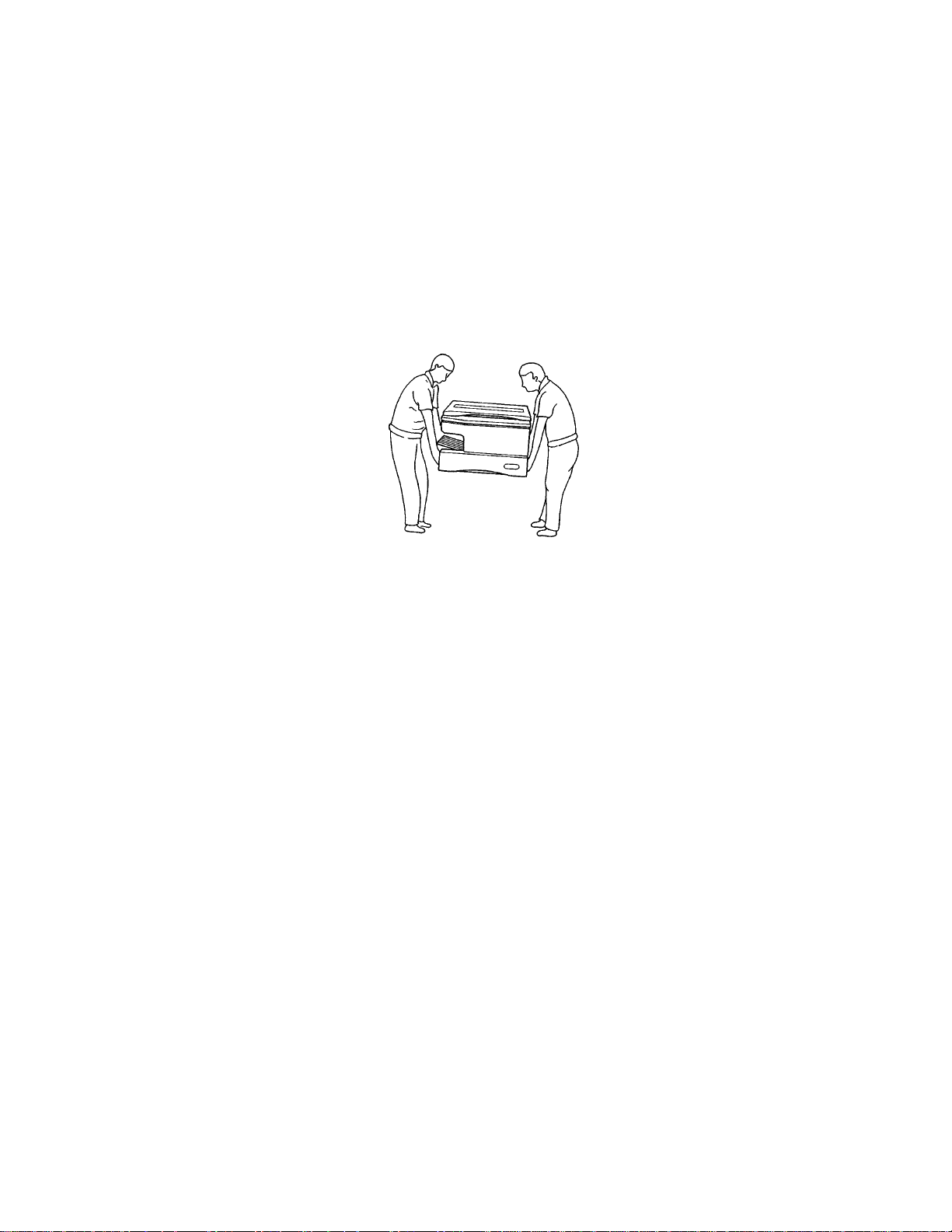
1. Transportation/Installation
• When transporting/installing the copier, using two persons, be sure to use the positions as indicated below.
The copier is fairly heavy and weighs approximately 35 kg (76.8 lb), therefore pay full attention
when handling it.
4 portions
2. Installation
• Be sure to use a dedicated outlet with AC 115V/15A (220V, 240V/10A) or more for its power
source.
• The copier must be grounded for safety.
Never ground it to a gas pipe or a water pipe.
• Select a suitable place for installation.
Avoid excessive heat, high humidity, dust, vibration and direct sunlight.
• To insure adequate working space for the copying operation, keep a minim um clearance of 80 cm
(31.5”) on the left, 80 cm (31.5”) on the right and 10 cm (3.9”) in the rear.
3. Service of Machines
• Basically, be sure to turn the main switch off and unplug the power cord during service.
• Be sure not to touch high temperature sections such as the exposure lamp, the fuser unit, the
damp heater and their periphery.
• Be sure not to touch high-voltages sections such as the chargers and the high-voltage transformer.
• Be sure not to touch rotating/operating sections such as gears, belts, pulleys, etc.
• When servicing the machines with the main switch turned on, be sure not to touch live sections
such as the lamp terminal etc.
• Use suitable measuring instruments and tools.
Page 3

4. Main Service Parts for Safety
• The thermofuse, thermistor, fuse, breaker and door s witch, etc. are particularly important for safety.
Be sure to handle/install them properly.
5. Notice Labels
• Be sure to check the rating plate and the notice labels such as “Unplug the power cord during
service”, “Hot area”, etc. to see if there is any dirt on their surface or if they are properly stuck to the
copier during servicing.
6. Disposition of Consumable Parts/Packing Materials
• Regarding the recovery and disposal of the copier, consumable parts and packing materials, it is
recommended to follow the relevant local regulations or rules.
7. When parts are disassembled, reassembly is basically the reverse of disassembly unless
otherwise noted in this manual or other related documents. Be careful not to reassemble
small parts such as screws, washers, pins, E-rings, toothed washers in the wrong places.
8. Basically, the machine should not be operated with any parts removed or disassembled.
Page 4
1. ADJUSTMENT ITEMS
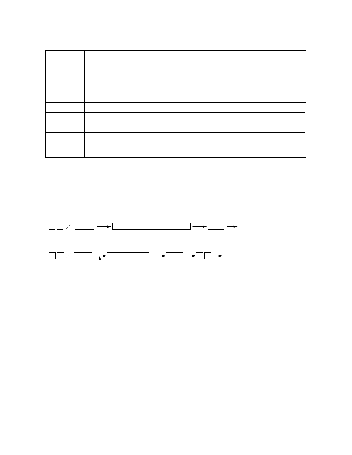
1.1 Error Code Table
When the “CLEAR PAPER” or “CALL SERVICE” symbol is flashing, pressing the “CLEAR/STOP” key
and the “8” key simultaneously causes one of the following error codes to be displayed while the keys are
pressed.
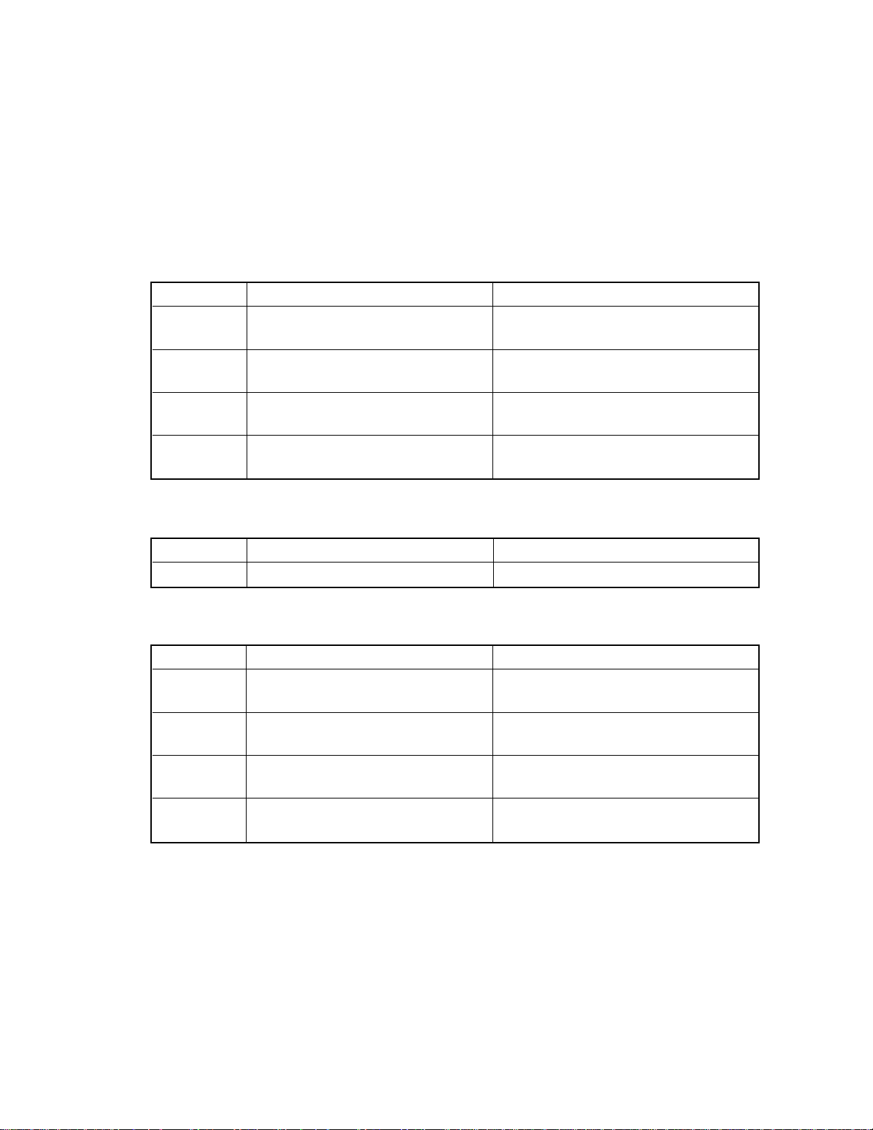
(1) Paper misfeeding in the copier paper path
Error code Content Remarks
E01 Paper misfeeding inside the copier Bypass misfeeding is also included.
(Bypass feeding LED comes ON.)
E02 Paper misfeeding in the neighborhood
of the fuser
E03 Paper misfeeding inside the copier when
the power is turned on.
E05 Non-arrival-at-aligning-switch misfeed- After the paper fed from PFU has passed
ing the transport roller or fed from PPC?
(2) Paper misfeeding in the paper feeding section
Error code Content Remarks
E14 Lower cassette paper misfeeding (PFU) Paper does not arrive at the transport roller.
(3) Paper misfeeding in the ADF transport path
Error code Content Remarks
E71 Misfeeding in the ADF original feeding
section
E72 Midfeeding in the ADF original transport
section
E73 Misfeeding in the ADF original exiting
section
E75 2 in 1 (2nd-original misfeeding in the
feeding section)
1 - 1Oct. 1995 © TOSHIBA CORP. 1550 ADJUSTMENT
Page 5
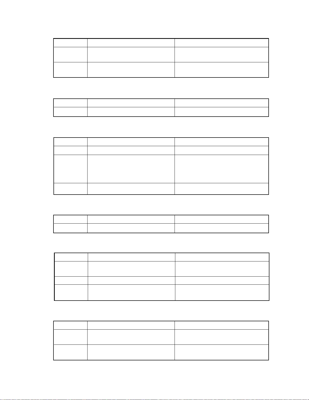
(4) Paper misfeeding in the sorter transport path
Error code Content Remarks
E81 Paper delaying jam in the sorter Paper does not arrive at the entrance
transport path sensor.
E82 Paper staying jam in the sorter Paper stays at the entrance sensor.
transport path.
(5) Service call for the copier’s drive system
Error code Content Remarks
C01 Abnormal operation of the main motor
(6) Service call for the optical system
Error code Content Remarks
C21 Optical system initialization error Scanning, lens or mirror abnormal operation.
C22 Optical system initialization error When the lens is moved in the paper exit
direction at the time of the start of
initialization,and only if it is not detected by
the switch.
C26 Blown exposure lamp detection
(7) Service call for the process system
Error code Content Remarks
C32 Easy setup (UA mode) error
(8) Fuser unit related
Error code Content Remarks
C41 Abnormal thermistor or broken heater
when the power is turned on.
C43 Abnormal thermistor during warming up.
C44 Heater breakage after the copier
becomes ready.
(9) Communication related service call
Error code Content Remarks
C54 Abnormal communication between the
C55 Abnormal communication between ADF
1550 ADJUSTMENT
sorter and the main CPU
and the main CPU
1 - 2
July 1996
®
Oct. 1995 © TOSHIBA CORP.
Page 6
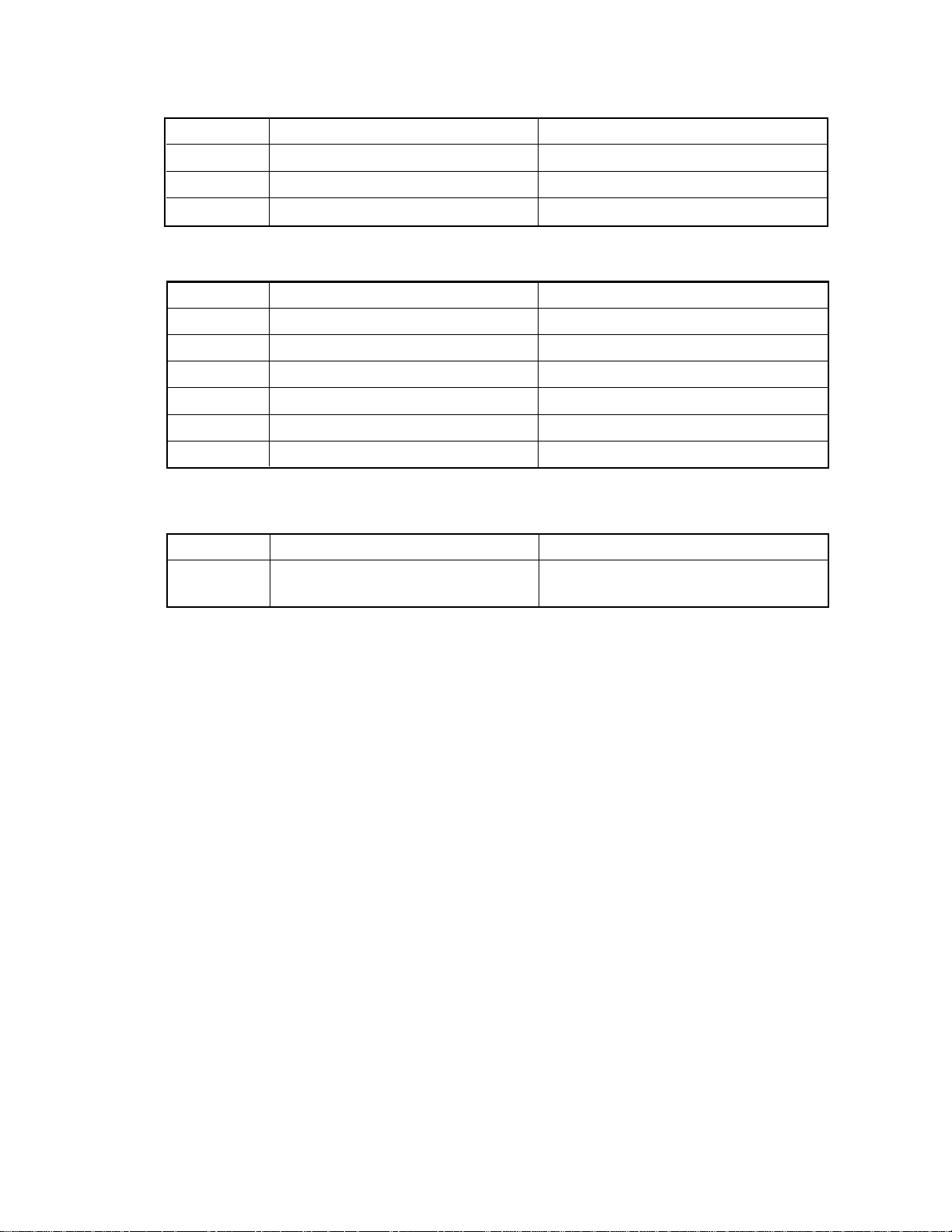
(10) ADF related
Error code Content Remarks
C71 Locked ADF main motor ADF jam LED is flashed.
C72 Maladjusted aligning sensor detection ADF jam LED is flashed.
C73 Faulty EEROM initialization ADF jam LED is flashed .
(11) Sorter related service call
Error code Content Remarks
C81 Abnormal paper transport motor
C82 Abnormal bin-moving motor
C83 Upper limit error
C84 Lower limit error
C85 Home sensor error
C88 Copy-removal sensor error
(12) Service call for other abnormalities
Error code Content Remarks
C94 Faulty optical system initialization in The content is similar to C21 error.
special modes (CH, AJ).
1 - 3Oct. 1995 © TOSHIBA CORP. 1550 ADJUSTMENT
Page 7
1.2 Self-Diagnostic Mode
Keys pressed
simultaneously
0+1
0+2 Aging mode Aging “09”
0+3 Test mode “09”
0+5 Adjustment mode Various adjustments “09”
0+6 Forced ready mode Forces the copier to become ready. —
0+7 Aging mode Aging (with ADF) “09”
0+8 Setting mode “09”
All control-panel LEDs
ON mode
Mode Description Clearing
All LEDs on the control panel come on.
Motor test and input/output check
(including initialization)
Motor test and input/output checkTest mode0+4 “09”
System changing and setting defaults and
PM counter
“Clear/Stop” key
Note: How to access each mode:
While pressing the two keys for the mode to access (ex. “0” and “5” for the adjustment mode), turn on the
main (power) switch.
<Procedure>
• All control-panel LEDs ON mode (01) :
Indication
—
AG
CH
CH
AJ
—
AG
AD
01
Power
All control-panel LEDs come on C/S Clear
• Aging mode (02) :
02
Power
Aging operation
PRINT
C/S 0 9 Clear
• Test mode (03 or 04) :
For this mode, refer to the “Input/Output Check” on page 1-6.
• Adjustment mode (05) :
For this mode, refer to the “Adjustment Mode” on page 1-9.
1550 ADJUSTMENT
1 - 4
Oct. 1995 © TOSHIBA CORP.
Page 8
•Forced ready mode (06) :
Power
06
Forced ready status
Note: This mode should be used only when checking paper feeding operation.
•Setting mode (08) :
For this mode, refer to “Setting Mode” on page 1-12.
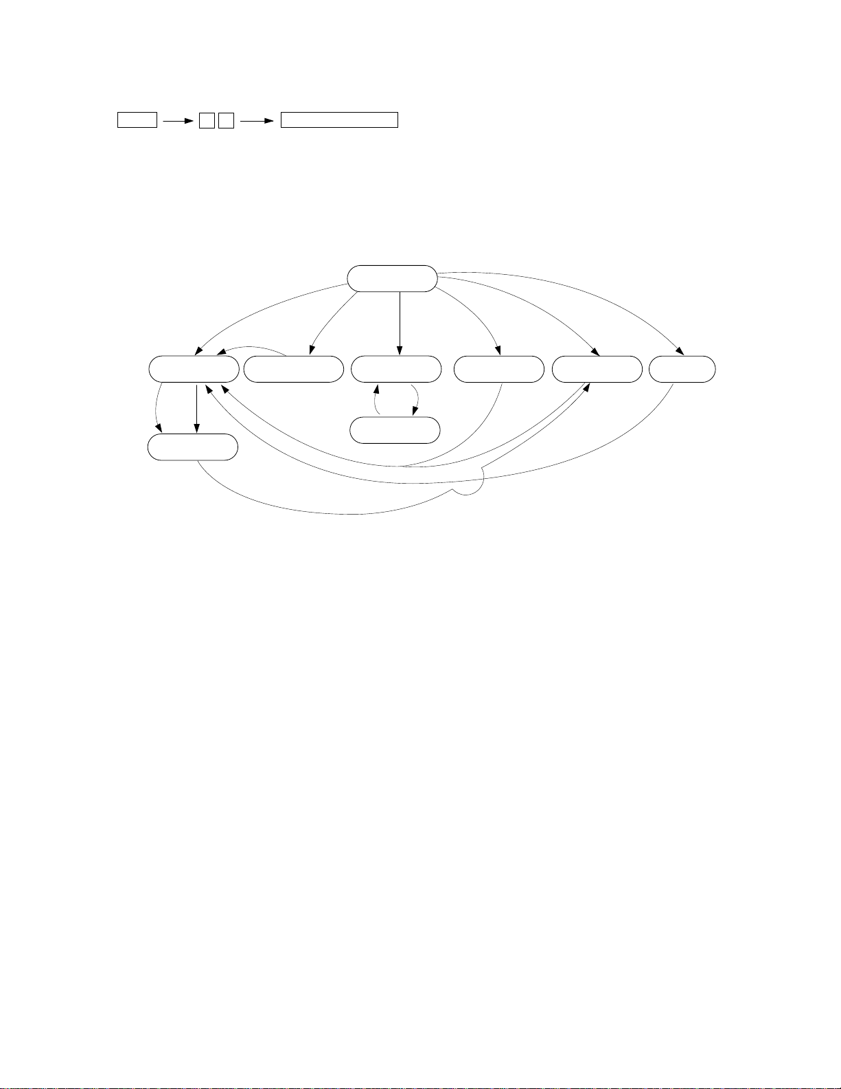
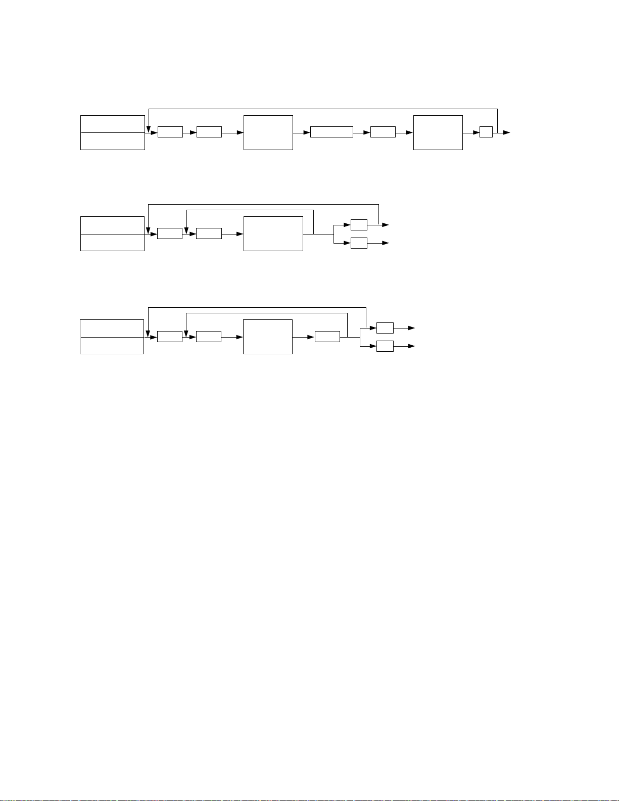
Self-diagnostic mode progress diagram :
Power ON
“06”
Warming up
Stand-by
“C”
All control-panel
LEDs ON
“01”
“05”
“02”
“07”
Aging
“P”
Temporary stop
“C”
“03/04”
Test mode
“09”
“05”
Adjustment mode Setting mode
“08”
“09” “09”
“P” : Press PRINT.
“C” : Press CLEAR/STOP.
1 - 5Oct. 1995 © TOSHIBA CORP. 1550 ADJUSTMENT
Page 9
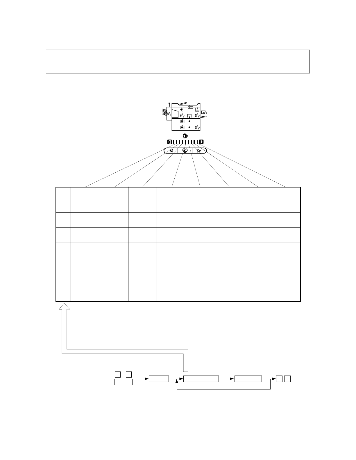
1.2.1 Input check (Test mode 03/04)
In the 03 or 04 test mode, you can check the status of each of the following input signals by pressing
the corresponding keys.
DARKLIGHT AUTO
Input
value
1
2 ————
3
4
5
6
7
EXP1
————
—
EMP-SW
(No paper)
RGT-SW
(Paper
present)
—
( ) means that LEDs come on.
*
EXP2
CTR-CNT
(No CTR)
EXIT-SW
(Paper
present)
CST2
(No cassette)
—
——
EXP3
HTR-RDY
(Not ready)
TNR-FUL
(Normal)
EMP-SW2
(No paper)
Paper width
sensor 2
(ON)
Removal
sensor
(ON)
Paper width
EXP4 EXP5 EXP6
DF-CNT
(No DF)
————
FED-SW
(Paper
present)
sensor 1
(ON)
Limit
sensor
(ON)
PFU cover
switch
(open)
S-CNT
(No sorter)
SIZ03
(OFF)
SIZ13
(OFF)
Empty sensor
(ON)
Bin-home
sensor
(ON)
Developer
unit switch
(none)
MRR-HOM
(Home
position)
SIZ02
(OFF)
SIZ12
(OFF)
Open sensor
One-rotation
sensor
(ON)
(ON)
EXP7 EXP8
Main motor
PLL
(NG)
LNS-HOM
(Home
position)
SIZ01
(OFF)
SIZ11
(OFF)
Exit sensor
(ON)
Paper-on-tray
sensor
(ON)
—
—
CRG-HOM
(Home
position)
SIZ00
(OFF)
SIZ10
(OFF)
Aligning
sensor
(ON)
Entrance
sensor
(ON)
1550 ADJUSTMENT
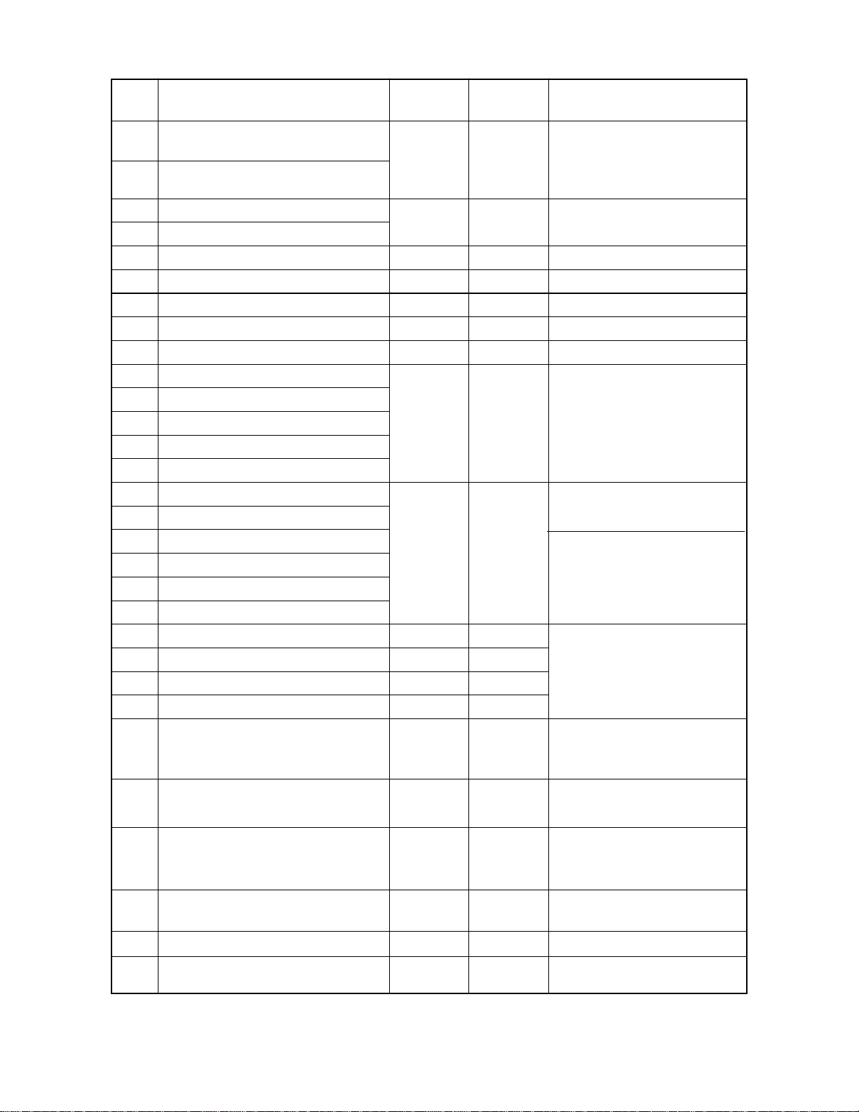
<Procedure>
03
Power
PRINT
1 - 6
Nemeric keys
LED ON
09
Oct. 1995 © TOSHIBA CORP.
Page 10
1.2.2 Output check mode (Test mode 03/04)
In the 03 or 04 test mode, you can check the status of each of the output signals by entering the
following corresponding code.
Code
1 Main motor
2 Feed roller clutch (copier)
3 Aligning roller clutch (copier)
6 Toner motor
7 Optics fan
8 Exit fan
9 Pick-up roller clutch (copier)
10 Total counter Increases at each “P” key press.
*1
20 Scanning motor At 1st “P” key press, scans forward and backward at 2nd press.
21 Lens motor At 1st “P” key press, moves to 50% position and to 200%
22 Mirror motor At 1st “P” key press, moves to 50% position and to 200%
30 HVT-M
31 HVT-TR
32 HVT-AC
33 Exposure lamp If forced on for 5 sec., it goes off.
61 PFU motor (PFU)
62 Pick-up roller clutch (PFU)
63 Feed roller clutch (PFU)
64 Aligning roller clutch (PFU)
80 DF independent aging At 1st “P” key press, starts and stops at 2nd press.
82 DF pick-up roller rotation
Function Code Function Group
64444474444448
ON
position at 2nd press.
position at 2nd press.
64748 64474448
At 1st “P” key press, comes on and goes off at 2nd press.
ON
11 Main motor
12 Feed roller clutch (copier)
13 Aligning roller clutch (copier)
16 Toner motor
17 Optics fan
18 Exit fan
19 Pick-up roller clutch (copier)
71 PFU motor (PFU)
72 Pick-up roller clutch (PFU)
73 Feed roller clutch (PFU)
74 Aligning roller clutch (PFU)
644444444474444444448
64444474444448
OFF
64474448
OFF
1
2
3
1
83 DF aligning roller
84 DF transport belt rotation
85 DF pick-up roller rotation/Weight solenoid
86 DF weight solenoid
87 DF clutch
90 Sorter transport motor
91 Sorter bin motor
92 Sorter aging without paper At 1st “P” key press, starts and goes off at 2nd press.
*1: Scanning motor rotates at the preset reproduction ratio.
At 1st “P” key press, comes on and stops at
2nd press.
1 - 7Oct. 1995 © TOSHIBA CORP. 1550 ADJUSTMENT
3
Page 11
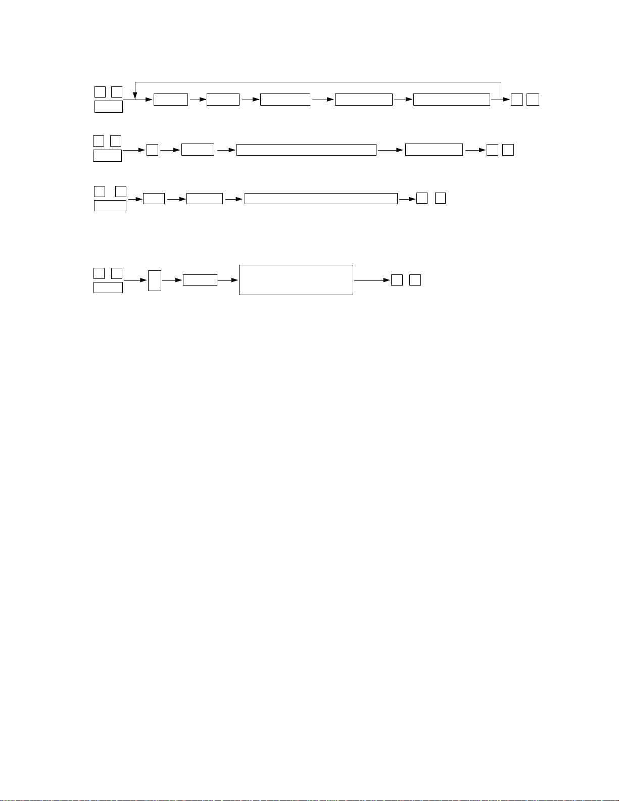
<Operation procedure>
Group 1
03/04
Power supply
Group 2
03/04
Power supply
Group 3
03/04
Power supply
Code Print
Code Print
Code Print
Operation
ON
Operation
(one direction)
Operation
(ON)
Stop code
Print
Print 09 Warm up
C/S
09
C/S
09
Oparation
OFF
Test mode standby state
Warm up
Test mode standby state
Warm up
1550 ADJUSTMENT
1 - 8
Oct. 1995 © TOSHIBA CORP.
Page 12

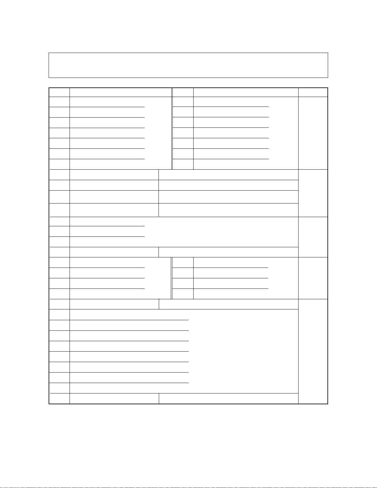
1.2.3 Adjustment mode (AJ: 05)
In this adjustment mode, the following items can be adjusted or modified. (Refer to the adjustment
code list.) The adjustment mode can be accessed b y turning on the power while pressing the “0” and
“5” keys simultaneously.
Code Description
*2
0 Automatic auto-toner adjustment — — Set to 24.
1 Manual exposure 100% 0~255 128 The larger, the lighter.
2 Manual exposure 154% 0~255 128 The larger, the lighter.
3 Manual exposure 50% 0~255 128 The larger, the lighter.
4 Manual exposure 200% 0~255 128 The larger, the lighter.
5 Auto-exposure 100% 0~255 128 The larger, the lighter.
6 Auto-exposure 154% 0~255 128 The larger, the lighter.
7 Auto-exposure 50% 0~255 128 The larger, the lighter.
8 Auto-exposure 200% 0~255 128 The larger, the lighter.
9 Exposure (light) Inclination 0~255 255
10 Exposure (dark) Inclination 0~255 0
14 Photo exposure 100% 0~255 128 The larger, the lighter.
Allowable Initial
input value value *1
Content
The larger, the lighter at the
light side.
The larger, the lighter at the
dark side.
15 Photo exposure 154% 0~255 128 The larger, the lighter.
16 Photo exposure 50% 0~255 128 The larger, the lighter.
17 Photo exposure 200% 0~255 128 The larger, the lighter.
Lengthwise reproduction
21
ratio adjustment
25 Eraser LED timing adjustment 100%
26 Eraser LED timing adjustment 200% 0~15 8
27 Eraser LED timing adjustment 50%
0~15 8
1 - 9Oct. 1995 © TOSHIBA CORP. 1550 ADJUSTMENT
Each increase by “1” causes the
lenthwise reproduction ratio to
increase by 0.1%
Each increase by “1” causes the
erased position by LED to shift
approx. 1mm toward the trailing
edge of the paper. But the
image position relative to the
paper does not change. (with
original surface as reference)
Page 13
Code Description
Eraser LED leading edge margin
30
adjustment
Eraser LED trailing edge margin
31
adjustment
35 Margin on the leading edge
36 Margin on the trailing edge
Allowable Initial
input value value *1
0~15 8
0~15 0
Content
Each increase by “1” causes the
erased position by LED to shift
1mm toward the trailing edge.
(with paper surface as reference)
0:No margin
1–15:Margin present (approx.
1mm/step)
38 Grid bias adjustment 0~255 128 The larger, the larger output.
39 Transfer transformer adjustment 0~255 128 The larger, the larger output.
40 Separation transformer adjustment 0~255 128 The larger, the larger output.
42 Grid bias adjustment (photo) 0~255 121 The value should be 121.
*3
49 Automatic auto-exposure adjustment — —
53 Leading edge (copier; 100%)
54 Leading edge (copier; 200%)
55 Leading edge (copier; 50%) 0~15 8
56 Leading edge (bypass feeding)
Each increase by “1” causes the
image to shift 0.80mm toward
the paper leading edge.
57 Leading edge position (PFU)
60 Lens position adjustment (100%)
61 Mirror position adjustment (100%)
Each increase by “1” moves
toward the exit side.
62 Enlargement correction (200%)
63 Enlargement error ratio (200%)
0~40 20
64 Reduction correction ( 50%)
65 Reduction error ratio ( 50%)
80 Aligning value (PFU) 0~31 8
Each increase by “1” causes the
paper to bend more.
81 Aligning value (short size) 0~31 16
82 Aligning value (copier) 0~31 8
83 Aligning value (B5) 0~31 16
Short size: A4/A5-R,LT/ST-R
B5: for B5 only
The adjustment sequence must
be 82
→89→81→83→80.
Each decrease by “1” causes
84 ADF aligning amount 0~15 8
the original stop position to shift
about 1mm toward the original
scale.
ADF original-to-original gap
87
(2 in 1 mode)
0~15 8
Each increase by “1” causes the
gap between the originals to
increase about 1mm.
Each increase by “1” causes
89 Aligning value (middle size) 0~31 16
the paper to bend more
Middle size: A4-R/B5-R/FOLIO,
LG,LT-R
90 Auto-toner adjustment 0~255 128
*4
97 ADF EEPROM initialization — —
*4
ADF aligning sensor
98
automatic adjustment
——
Shows the adjustment value of
the auto toner sensor.
*1: The initial value signifies the value set by the NV-RAM initialization program and not the value set at the time
of shipping from the factory.
1550 ADJUSTMENT
1 - 10
®
July 1996
Oct. 1995 © TOSHIBA CORP.
Page 14
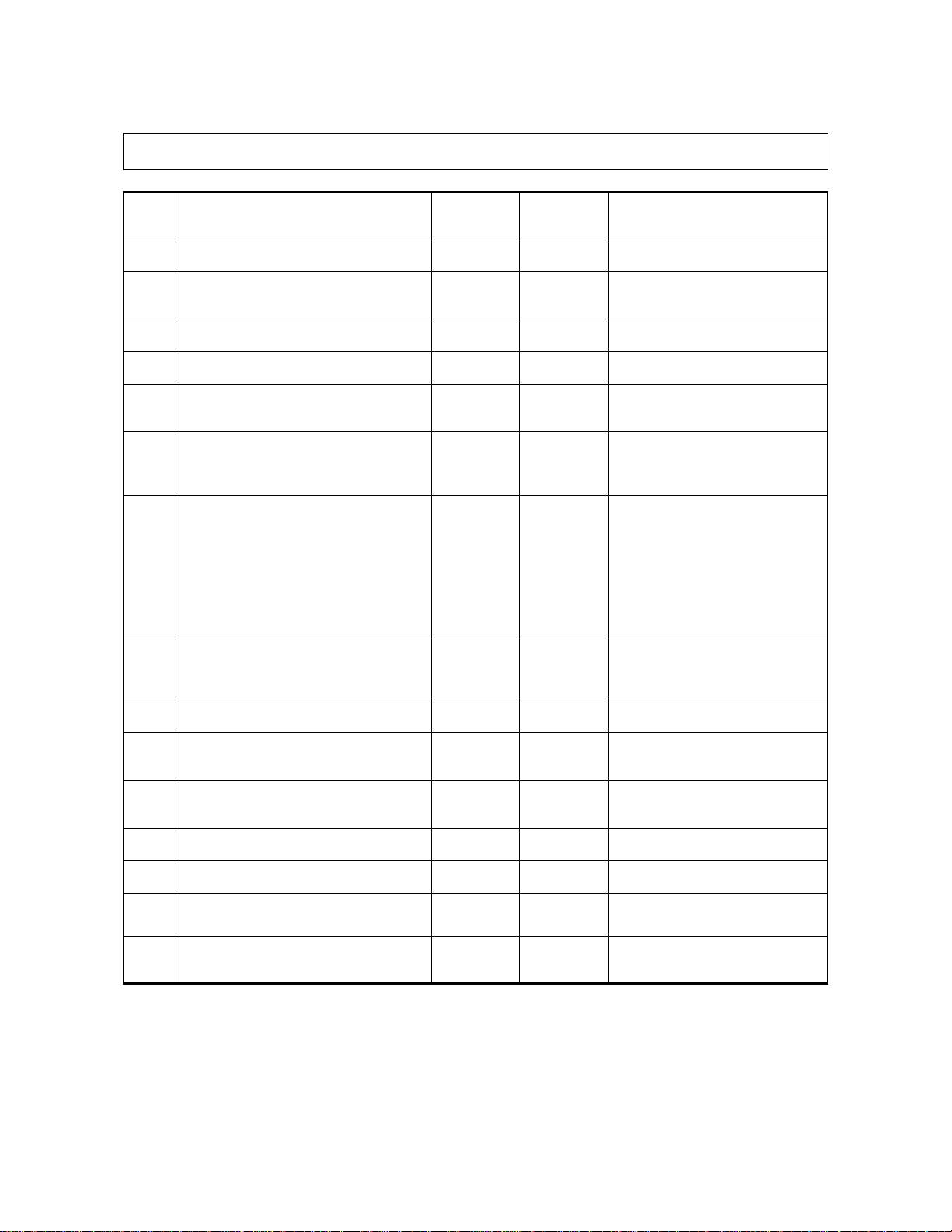
<Procedure>
0
5
Power
*2
05
Power
0
Code
PRINT
PRINT
Adjustment
Automatic auto-toner adjustment
INTERRUPT
Memorize
ENERGY SAVER
Test copy
INTERRUPT
Memorize
09
Clear
0
Clear
9
*3
*4
5
0
Power
05
Power
49
97
98
PRINT
PRINT
Automatic auto-exposure adjustment
ADF EEROM initialization
ADF Aligning roller
automatic adjustment
Ends 2
sec.
later.
09
Clear
(Possible only after the
automatic adjustment
is completed.)
09
Clear
1 - 11Oct. 1995 © TOSHIBA CORP. 1550 ADJUSTMENT
Page 15
1.2.4 Setting mode (08)
In this mode, it is possible to set or modify the various modes shown in the following setting code list.
Code Description
2 Size indication by the carriage 0, 1 1 0: None; 1: Available
4 Automatic sort mode 0~3 0
7 Access control mode 0, 1 0 0: None; 1: Available
8 Version 0~2 Each version 0: EUR; 1: UC; 2: JPN
9 ACT selection (reproduction ratio
in the direction of copy movement) 1: UC
10 Timer mode (auto reset) 0~10 3 (45 sec.) 2: 30sec.; 3: 45 sec.
11 Auto power saving 0~15 0
12 Maximum number of copies 0~3 0 1: Max. 99; 2: Max. 9
Allowable Initial
input value value
0, 1
0: EUR
Content
0: None;
1, 2: Sort; 3: Group
0: 100%; 1: 101%
0: None; 1: 15 sec.
4: 60 sec.; N:
0: None; 1: 30 sec.
2: 60 sec.; 3: 90 sec.
4: 120 sec.; 5: 150 sec.
6: 3 min.; 7: 4 min.
8: 5 min.; 9: 7 min.
10: 10 min.; 11: 15 min.
12: 20 min.; 13: 30 min.
14: 45 min.; 15: 60 min.
0: Max. 999 copies
3: Max. 500
N x15 sec.
13 Paper feeding retry 0,1 0 0: Retry; 1: No retry
14 Cassette priority selection 0~4 0
15 Exposure priority selection 0~2 0
16 A3-size double counting 0,1 0 0: Single count; 1: Double count
17 Bypass auto start 0,1 0 0: Manual start; 1: Auto start
19 Sorter priority selection 0~3 0
20 Pre-run ON/OFF 0~15 0
1550 ADJUSTMENT
1 - 12
0: A4/LT
3: Copier; 4: PFU
0: Auto; 1: Manual
3: Photo mode
0: Non-sort;
1, 2: Sort; 3: Group
0: OFF
N x10 sec.
1~15:
Oct. 1995 © TOSHIBA CORP.
Page 16
Code Description
21 Auto cassette change 0,1 1 0: None; 1: Available
Allowable Initial
input value value
Content
22 ADF mode 0~5 0 2: AMS; 3: 2 in 1+AMS
23 Thick paper selection at bypass
pre-running
27 ADF’s APS mode 0~2
Pressing PRINT after suspension of
28
APS/AMS
37 Default sorter key selection 0,1 0 0: Normal; 1: Sort default
38 Heater temperature during power saving 0~7 0 4: 150°C; 5: 160°C
44 All clearing after copying 0,1 0 0: None; 1: Available
51 Easy set-up method (UA mode) 0,1 0 0: No; 1: Yes
52 Quick copy mode 0,1
53 Broken exposure lamp detection 0~2 0
0,1 0 0: None; 1: Available
0: UC
1: EUR
0~2 0 1: 2nd Copying possible
0: EUR
1: UC
0: Manual; 1: APS
4: 2 in 1+APS 5: 2 in
0: Detection for each original;
1: Detection for 1st original only;
2: Prevents copying blank originals
0: 1st copying possible
2: Copying not possible
0: Heater off; 1: 120°C
2: 130°C; 3: 140°C
6: 170°C; 7: 180°C
0: None; 1: Available
0: All exposure modes
1: Auto only; 2: None
54 Coin-vender mode 0,1 0 0: None; 1: Available
58 Reproduction-ratio display time 0~15 0 2+0.2xN sec.
59 LG size 0,1 0 0: 14 inch; 1: 13 inch
62 AMS copy stop switching 0,1 0
63 DF key selection order switching 0,1 → 2in1 + APS → 2in1
69 PM counter setting 0~999,999 0 Other than 0: When set value
79 Current PM counter value 0~999,999 0
0: EUR
1: UC
0: No stop;
1: Temporary stop
0: APS → AMS → 2in1 + AMS
0: APS → AMS → 2in1 + AMS
0:No PM counter;
< code 79, PM call occurs.
<Procedure>
0
Power
8
Code
PRINT
Setting or
modifying
the value
INTERRUPT
Memorize
0
Clear
9
1 - 13Oct. 1995 © TOSHIBA CORP. 1550 ADJUSTMENT
Page 17
Code Description
89 Heater abnormal counter 0~7 0
Error code Code 89 Timing of the error Cause of the error
C41 1
C43 4 During warming up
Allowable Initial
input value value
Value
When the power is
turned on
2
Content
Abnormal thermistor
(disconnection) or broken
heater
Abnormal thermistor
(disconnection)
5
C44 6
Absent (normal) 0 --- ---
• When the power is the turned on, if an abnormality occurs, the C41 “CALL
SERVICE” symbol will flash, and the value of the setting mode code 89 will
be counted up.
• When the Code 89 value is 0~1, rewarming up is performed by turning on the
machine again.
If the value is 2 or more, “CALL SERVICE” symbol will flash immediately.
• If an abnormality occurs during warming up or the standby mode, C43 or
C44 “CALL SERVICE” symbol will flash immediately, and the value of the
setting mode code 89 depends on the conditions present at the time of the
occurrence.
After the finish of
warming up
7
Broken heater
Abnormal thermistor
(disconnection)
Broken heater
1550 ADJUSTMENT
1 - 14
® July 1996
Oct. 1995 © TOSHIBA CORP.
Page 18
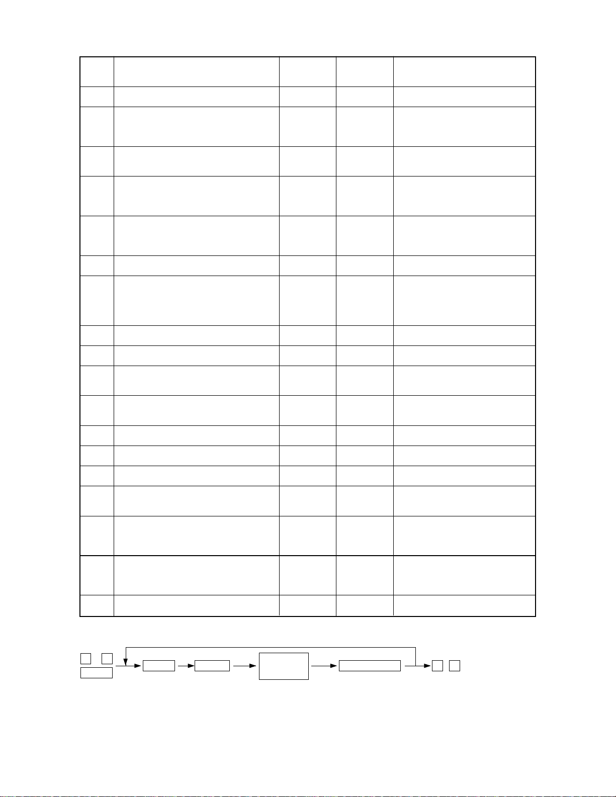
1.3.A Installing the Carriage Drive Wire
(1) Set the wire so that its spherical terminal is
placed in the hole of the wire take-up pulley.
Spherical terminal
Wire takeup pulley
(2) Using the wire holder jig, wrap the wire on the
take-up pulley, 3-1/4 turns of the fixture-side
Wire take-up pulley
end and 5-1/4 turns of the other end.
Wire holder jig
(3) Wrap the wires on the front and rear sides, as shown and fasten them with screws.
[Front side]
Hook (feed side)
Front side wire fixture
(Marking “F”)
Hook (feed side)
[Rear side]
Rear side
wire
fixture
(Marking
“R”)
1
5 turns
4
closely fit
Spherical terminal
1
3 turns
4
closely fit closely fit
Shaft
1 - 15Oct. 1995 © TOSHIBA CORP. 1550 ADJUSTMENT
1
3 turns
4
1
5 turns
4
closely fit
Page 19
(4) Install carriage 2.
(5) As shown on figure , attach the wires.
[Feed side]
Wire fixing 1
8.5 turns
4
1
Shaft
Fixed to CRG 1
CRG 2
2
3
6
View as seen from the rear
[Exit side]
Wire fixing 7
5
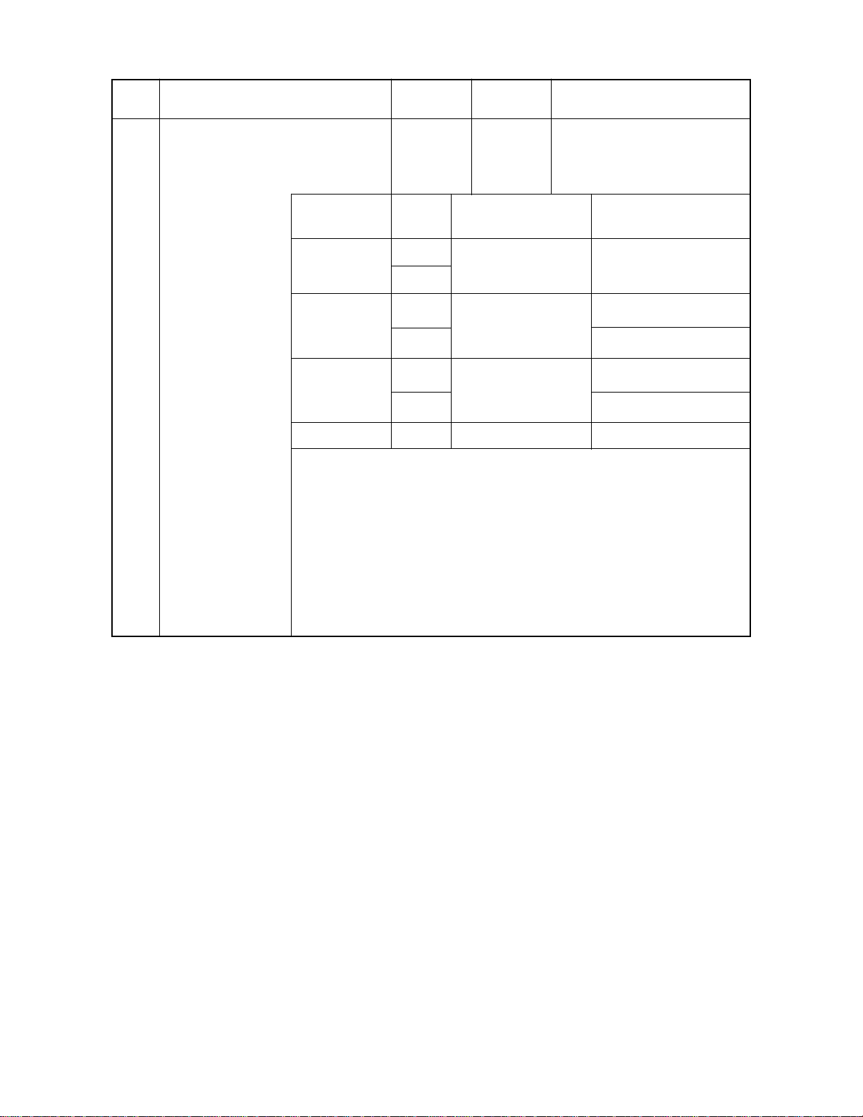
1.3.B Adjusting the Carriage Wire Tension
After having removed the wire, adjust the tension of the wire with the adjustment screw so that the exit
side leaf spring will be deflected as shown in the drawing below.
Also, always adjust the positions of the carriage 1 and 2 after finishing the tension adjustment.
Carriage drive wire
(12.8)
(Before) (After)
(Deflect it by
2 mm)
(14.8)
Hook
Adjustment
screw
Wire tension
bracket
1550 ADJUSTMENT
1 - 16
Oct. 1995 © TOSHIBA CORP.
Page 20

1.4 Position Adjustment of Carriage 1 and 2
(1) While pushing carriage 2 to exit side, tighten
the screw on the front.
(2) Fasten carriage 1 to the wire: Each screw on
the front and rear should be tightened temporarily.
(3) While pushing carriage 1 to the exit side (car-
riage 2), tighten the screws
[Exit side]
Carriage 2
[Exit side]
..... on the front and rear.
Note: Move carriages 1 and 2 to the exit side by
rotating the shaft and check to make sure
that the claws of both carriages (two for each)
touch the inside surface of the frame at the
same time.
Carriage 1
1 - 17Oct. 1995 © TOSHIBA CORP. 1550 ADJUSTMENT
Page 21

1.5 Light Distribution Adjustment
(1) Remove the glass holder (2 screws) and then
the original glass.
(2) Move light-distribution adjustment plate 1 -
3 in the direction of the arrow (@), depend-
ing on the amount of uneven light distribution.
Light-distribution adjustment plate 1
1
Adjustment should be made so that the image becomes darker evenly.
(3) Move light-distribution adjustment plates 1
and 2 in the direction of the arrow.
(When the rear side is darker)
(4) Move light-distribution adjustment plates 2
and 3 in the direction of the arrow.
(When the front side is darker)
Light-distribution
adjustment
plate 2
Light-distribution
adjustment
plate 3
2
3
Direction of movement
Direction of movement
As a result of the above adjustment, there is a possibility that under-exposure or over-exposure may
occur; make exposure adjustment if necessary.
1550 ADJUSTMENT
1 - 18
Oct. 1995 © TOSHIBA CORP.
Page 22

1.6 Image Slanting and Image Distortion Adjustment
(1) Image slanting adjustment
Direction of movement Direction of movement
Image
Paper
A
B
After making a copy with the original aligned correctly with the original scale, if the copy image is
slanting, adjustment should be made by moving the
front side of the original scale.
Slanting as in A:
Adjust the original scale in the direction of the ar-
A
row (
).
Slanting as in B:
Adjust the original scale in the direction of the ar-
A
row (
).
Original scale
1 - 19Oct. 1995 © TOSHIBA CORP. 1550 ADJUSTMENT
Page 23

(2) Image distortion adjustment
Step 1
AB
Direction of movement
Step 2
CD
<Adjustment procedure>
After removing the original glass, make adjustment
using the following procedure:
Step 1: If the image is distorted as in
A or B, make adjustment in
the direction of copy movement
using the mirror 2's adjustment
screw to make the image as in
C or D:
Direction of movement
Mirror 2
A
B
In the case of A: Rotate the adjustment screw in
the direction of tightening
(clockwise).
In the case of B: Rotate the adjustment screw in
the direction of loosening
(counter-clockwise).
1550 ADJUSTMENT
1 - 20
Oct. 1995 © TOSHIBA CORP.
Page 24

Step 2: If the image is distorted as in
C or D, using the mirror unit's
adjustment screw , make adjustment in the direction perpendicular to that of copy movement to make the image normal:
In the case of C: Rotate the adjustment screw in
the direction of tightening
(clockwise).
In the case of D: Rotate the adjustment screw in
the direction of loosening
(counter-clockwise.)
D
C
July 1996
1 - 21Oct. 1995 © TOSHIBA CORP. 1550 ADJUSTMENT
®
Page 25

1.7 Mirror and Lens Adjustment
Checking and adjustment regarding the mirrors and the lens should be made by using the following
procedure:
Focus/lateral reproduction-ratio adjustment
(60) ~ (65) Carriages 1/2 Mirrors 1/2
Slanted image
adjustment
Original scale (60) ~ (65)
Note: Do adjustment steps in the dotted-line boxes, as required.
Carriages 1/2
adjustment
Focus/lateral reproduction-ratio adjustment
Inclined focus
adjustment
Lens unit
Mirror unit
Lateral deviation
adjustment
Lens unit
Image distortion
Focus/lateral reproduction-ratio adjustment AJ: Codes 60 - 65
When the lens is replaced or when the focus or the lateral reproduction ratio is not correct, the following
adjustment data need to be re-entered:
Allowable input value Center value
Lens position data (100%) (AJ"05" mode, code 60) 0~40 20
Mirror position data (100%) (AJ"05" mode, code 61) 0~40 20
Lens position data (200%) (AJ"05" mode, code 62) 0~40 20
Mirror position data (200%) (AJ"05" mode, code 63) 0~40 20
Lens position data (50%) (AJ"05" mode, code 64) 0~40 20
Mirror position data (50%) (AJ"05" mode, code 65) 0~40 20
Adjustment should be done as follows:
Lens/mirror position values Mirror position value
100 %
(60)
Mirror position value
50 %
(65)
Normally, adjustment steps in the dotted-line boxes are unnecessary.
100 %
(61)
Lens position value
50 %
(64)
200 %
(63)
Lens position value
200 %
(62)
[A] 100% focus and lateral reproduction-ratio adjustment
(1) Make an actual-sized copy and check for the correct focus and lateral reproduction ratio; if adjust-
ment is necessary, re-enter adjustment data as described below:
a If the focus is inadequate and lateral reproduction ratio is smaller:
Enter a smaller mirror-position value (code 61).
1550 ADJUSTMENT
1 - 22
Oct. 1995 © TOSHIBA CORP.
Page 26

b If the focus is inadequate and the lateral reproduction ratio is enlarged:
Enter a larger mirror-position value (code 61).
c If the focus is adequate but the lateral reproduction ratio is reduced:
Enter a larger lens-position value (code 60).
d If the focus is adequate but the lateral reproduction ratio is increased:
Enter a smaller lens-position value (code 60).
Notes: 1. Moving either the lens or the mirror changes both the focus and the lateral reproduction ratio.
Howev er , the lens-position v alue mainly changes the lateral reproduction r atio and the mirror
position value mainly changes the focus.
2. First adjust the focus, then the lateral reproduction ratio and check the focus again.
3. If the lateral reproduction ratio is not precisely adjusted (within ±0.5%), the focus cannot be
correctly adjusted either.
4. The focus in the center of the image has more margin than that of any of the four corners of
the image due to the characteristics of the lens.
5. For 200% and 50% reproduction ratios, adjustment of the normal focus (mirror position)
makes the lateral reproduction ratio optimal, making it unnecessary to be adjusted.
[B] 200% focus and lateral reproduction-ratio adjustment
(1) Make a 200% copy and check for the correct focus and lateral reproduction ratio.
(2) When the focus and the lateral reproduction ratio are inadequate, re-enter the values of codes 62
and 63 in the AJ "05" mode in the same way as for 100%.
[C] 50% focus and lateral reproduction ratio adjustment
(1) Make a 50% copy and check for the correct focus and lateral reproduction ratio.
(2) When the focus and the lateral reproduction ratio are inadequate, re-enter the values of codes 64
and 65 in the AJ "05" mode in the same way as for 100 %.
1.8 Adjustment of Lateral Misplacement of the Lens Unit
The lens unit has adjustable mechanism.
However, as the adjustment is performed at the time of shipping from the factory, no further adjustment
is needed.
July 1996
1 - 23Oct. 1995 © TOSHIBA CORP. 1550 ADJUSTMENT
®
Page 27

1.9 Exposure Adjustment
(1) While pressing keys "0" and '5" sim ultaneously, turn the power supply ON. The display shows "AJ"
and indicates that the machine is in adjustment mode.
(2) Press the automatic exposure key to set the machine to manual exposure, and then select the
center step.
(3) Adjust the exposure in accordance with the procedure shown in the chart below.
Adjustment
sequence ratio
1 Manual exposure 100% 1
2 Automatic adjustment of automatic exposure 50 ~ 200% 49
*3 Light (max.) 9
*4 Dark (min.) 10
5 Manual photo exposure 100% 14
* Make adjustment only when requested by the user.
Exposure mode
Reproduction
100% or
appropriate
reproduction
ratio
Adjustment code
When individual adjustment is required for manual, automatic and manual photo exposure in response to
a request from the user, follow procedure (4).
1 Adjustment of 100% manual exposure
Sequence Operation Display after operation (typical)
1-1 Input code "1" using the digital keys , and press the "Print" key. 120
1-2 [When density is high] (Note 1)
Increase the numerical value, using the "Zoom" key. (Note 2) 129 Zone A
[When density is low]
Reduce the numerical value, using the "Zoom" key. (Note 2) 180
1-3 Press the "Interrupt" key and enter the numerical value in the
memory.
1-4 Press the “Energy saver” key and make a test copy (one) AJ
1-5 If the image of the test copy is not satisfactory, repeat
operations 1-1 through 1-4.
Note 1. Zone A: When the "Zoom" key is pressed, it increases (or decreases) in increments of one.
2. The numerical value in Zone A can be changed by using the digital keys as well as the "Zoom" key.
3. As adjustment of 154%, 50% and 200% manual exposure has already been performed, readjustment is
not required. How e v er , if individual adjustment is requested b y the user, conduct the relevant adjustment
in accordance with procedure (4), described later.
1550 ADJUSTMENT
1 - 24
6447448
Oct. 1995 © TOSHIBA CORP.
Page 28

2 Automatic adjustment of automatic exposure
Sequence Operation Display after operation (typical)
2-0
2-1
2-2
Note 1. As automatic adjustment of automatic exposure is performed on the basis of manual exposure, be sure to
When changing the variable width of the ke y for manual e xposure in accordance with the user’ s request, carry out 3
and 4, described below.
Be sure to adjust manual exposure (100%) beforehand. (Note1)
Place the adjustment chart on the original glass. (Note 2)
Enter code 49 using the digital keys and then press the Print ke y.
* During automatic adjustment, the carriage will shift and the lens
and mirror will move in accordance with the reproduction ratio.
The exposure lamp will flash four times.
* End of automatic adjustment is indicated by return of the display
to test mode.
conduct manual exposure beforehand.
2. Use white Ledger or A3 copy paper as the test chart.
3. When adjustment must be performed in accordance with the user’s request, perf orm by referring to (4), to
be described later.
4. Avoid opening the original cover, pressing keys on the control panel or turning the power OFF, during
automatic adjustment.
Refer to 1
AJ
169
199
AJ
3 Changing the amount of variation in the light image density
Sequence Operation
3-1 Input code “9” using the digital keys and press the “Print” key.
3-2 Use the “Zoom” key to increase the value to lighten the image (and vice versa).
3-3 Press the “Interrupt” key to store the value.
3-4 Press the “Energy saver” key and make a test copy.
3-5 If the image density of the test copy is not satisfactory, repeat operations 3-1 through 3-4.
4 Changing the amount of variation in the dark image density.
Sequence Operation
4-1 Input code “10” using the digital keys and press the “Print” key.
4-2 Use the “Zoom” key to increase the value to lighten the image (and vice versa).
4-3 Press the “Interrupt” key to store the value.
4-4 Press the “Energy saver” key and make a test copy.
4-5 If the image density of the test copy is not satisfactory, repeat operations 4-1 through 4-4.
1 - 25Oct. 1995 © TOSHIBA CORP. 1550 ADJUSTMENT
Page 29

5 100% manual photo exposure adjustment
Sequence Operation Display after operation (typical)
5-1
5-2
5-3
5-4
5-5
Input code “14” using the digital keys, and press the “Print” key.
[When density is high]
Increase the numerical value, using the “Zoom” key.
[When density is low]
Decrease the numerical value, using the “Zoom” key.
Press the “Interrupt” key and store the numerical value in the
memory.
Press the “Energy saver” key and make a test copy.
If the image density of the test copy is not satisfactory, repeat
operations 5-1 through 5-4.
1442443
128
138
118
AJ
(4) Adjust exposure in accordance with the procedures shown in the charts below, if requested by the
user for separate adjustment of manual/auto-exposure.
Adjustment
sequence ratio
1 100% 1
2
3 50% 3
Manual exposure center
Exposure mode
Reproduction
154% 2
Adjustment code
4 200% 4
5 100% 5
6
7 50% 7
8 100% 8
9 Light (max.) 9
10 Dark (min.) 10
11 100% 14
12
13 50% 16
14 200% 17
Automatic exposure
Manual photo exposure
154% 6
100 % or
appropriate ratio
154% 15
1550 ADJUSTMENT
1 - 26
Oct. 1995 © TOSHIBA CORP.
Page 30

1 Perform the 100% manual exposure adjustment (3)- 1.
2 154% manual exposure adjustment
Sequence Operation Display after operation (typical)
2-1
2-2
Input code “2” using the digital keys, and press the “Print” key.
[When density is high]
Increase the numerical value, using the “Zoom” key.
130
149
[When density is low]
2-3
2-4
2-5
Decrease the numerical value, using the “Zoom” key.
Press the “Interrupt” key and store the numerical value in the
memory.
Press the “Energy saver” key and make a test copy.
If the image density of the test copy is not satisfactory, repeat
operations 2-1 through 2-4.
443
144424
126
AJ
3 50% manual exposure adjustment
Sequence Operation Display after operation (typical)
3-1
3-2
Input code “3” using the digital keys, and press the “Print” key.
[When density is high]
Increase the numerical value, using the “Zoom” key.
[When density is low]
Decrease the numerical value, using the “Zoom” key.
103
109
096
3-3
3-4
3-5
Press the “Interrupt” key and store the numerical value in the
memory.
Press the “Energy saver” key and make a test copy.
If the image density of the test copy is not satisfactory, repeat
operations 3-1 through 3-4.
443
AJ
144424
4 200% manual exposure adjustment
Sequence Operation Display after operation (typical)
4-1
4-2
4-3
4-4
4-5
Input code “4” using the digital keys, and press the “Print” key.
[When density is high]
Increase the numerical value, using the “Zoom” key.
[When density is low]
Decrease the numerical value, using the “Zoom” key.
Press the “Interrupt” key and store the numerical value in the
memory.
Press the “Energy saver” key and make a test copy.
If the image density of the test copy is not satisfactory, repeat
operations 4-1 through 4-4.
443
144424
175
186
166
AJ
1 - 27Oct. 1995 © TOSHIBA CORP. 1550 ADJUSTMENT
Page 31

5 100% automatic exposure adjustment
Sequence Operation Display after operation (typical)
5-1
5-2
Input code “5” using the digital keys, and press the “Print” key.
[When density is high]
Increase the numerical value, using the “Zoom” key.
115
127
[When density is low]
5-3
5-4
5-5
Decrease the numerical value, using the “Zoom” key.
Press the “Interrupt” key and store the numerical value in the
memory.
Press the “Energy saver” key and make a test copy.
If the image density of the test copy is not satisfactory, repeat
operations 5-1 through 5-4.
44314
144424
107
AJ
6 154% automatic exposure adjustment
Sequence Operation Display after operation (typical)
6-1
6-2
Input code “6” using the digital keys, and press the “Print” key.
[When density is high]
Increase the numerical value, using the “Zoom” key.
[When density is low]
Decrease the numerical value, using the “Zoom” key.
127
139
113
6-3
6-4
6-5
Press the “Interrupt” key and store the numerical value in the
memory.
Press the “Energy saver” key and make a test copy.
If the image density of the test copy is not satisfactory, repeat
44314
AJ
4424
operations 6-1 through 6-4.
7 50% automatic exposure adjustment
Sequence Operation Display after operation (typical)
7-1
7-2
7-3
7-4
7-5
Input code “7” using the digital keys, and press the “Print” key.
[When density is high]
Increase the numerical value, using the “Zoom” key.
[When density is low]
Decrease the numerical value, using the “Zoom” key.
Press the “Interrupt” key and store the numerical value in the
memory.
Press the “Energy saver” key and make a test copy.
If the image density of the test copy is not satisfactory, repeat
operations 7-1 through 7-4.
443
4424
094
087
103
AJ
1550 ADJUSTMENT
1 - 28
Oct. 1995 © TOSHIBA CORP.
Page 32

8 200% automatic exposure adjustment
Sequence Operation Display after operation (typical)
8-1
8-2
Input code “8” using the digital keys, and press the “Print” key.
[When density is high]
Increase the numerical value, using the “Zoom” key.
141
149
[When density is low]
8-3
8-4
8-5
Decrease the numerical value, using the “Zoom” key.
Press the “Interrupt” key and store the numerical value in the
memory.
Press the “Energy saver” key and make a test copy.
If the image density of the test copy is not satisfactory, repeat
operations 8-1 through 8-4.
443
144424
133
AJ
9 When changing the variable width of the key for manual exposure at the user’s request, change the
amount of variation in the light/dark image density in (3)- 3 and 4.
!º Perform the 100% manual photo exposure adjustment in (3)- 5.
!¡ 154% manual photo exposure adjustment
Sequence Operation Display after operation (typical)
11-1
11-2
Input code “15” using the digital keys, and press the “Print” key.
[When density is high]
Increase the numerical value, using the “Zoom” key.
128
138
[When density is low]
11-3
11-4
11-5
Decrease the numerical value, using the “Zoom” key.
Press the “Interrupt” key and store the numerical value in the
memory.
Press the “Energy saver” key and make a test copy.
If the image density of the test copy is not satisfactory, repeat
operations 11-1 through 11-4.
443
144424
118
AJ
!™ 50% manual photo exposure adjustment
Sequence Operation Display after operation (typical)
12-1
12-2
12-3
12-4
12-5
Input code “16” using the digital keys, and press the “Print” key.
[When density is high]
Increase the numerical value, using the “Zoom” key.
[When density is low]
Decrease the numerical value, using the “Zoom” key.
Press the “Interrupt” key and store the numerical value in the
memory.
Press the “Energy saver” key and make a test copy.
If the image density of the test copy is not satisfactory, repeat
operations 12-1 through 12-4.
443
144424
128
138
118
AJ
1 - 29Oct. 1995 © TOSHIBA CORP. 1550 ADJUSTMENT
Page 33

!£ 200% manual photo exposure adjustment
Sequence Operation Display after operation (typical)
13-1
13-2
13-3
13-4
13-5
Input code “17” using the digital keys, and press the “Print” key.
[When density is high]
Increase the numerical value, using the “Zoom” key.
[When density is low]
Decrease the numerical value, using the “Zoom” key.
Press the “Interrupt” key and store the numerical value in the
memory.
Press the “Energy saver” key and make a test copy.
If the image density of the test copy is not satisfactory, repeat
operations 13-1 through 13-4.
128
138
118
443
AJ
144424
1550 ADJUSTMENT
1 - 30
Oct. 1995 © TOSHIBA CORP.
Page 34

1.10 Checking and Adjustment of Grid Bias/Transfer/Separation Output
Checking and adjustment of grid bias/transfer/separation output is necessary when the high-voltage transformer is replaced.
At adjustment mode "05" "38" grid bias (Black)
"39" transfer charger
"40" separation charger
64448
Notes: 1. A digital tester with an input resistance of 10 MΩ or more should be used.
<Adjustment procedure>
1. Take out the process unit, and then remove
the developer unit, main charger unit and
drum.
2. Remove the main blade.
3. Using the drum shaft, install the adjustment
jig in the cleaner unit and then set the main
charger unit.
4. Set the process unit into the copier and fasten the earth wire of the jig to the machine
frame with a screw. Then connect the black
(WH) side of the jig’s 3P-connector to the (–)
terminal and the red (WH) side to the (+) terminal of the digital tester, respectively.
5. Push down the upper unit. (Be careful not to
allow the jig’s cord to be pinched).
Jig
Earth wire
3P connector
For measuring the transfer/separation values
1 - 31Oct. 1995 © TOSHIBA CORP. 1550 ADJUSTMENT
Page 35

6. Turn on the door switch forecefully.
Note: When measuring the grid bias*, route the (+) terminal of the digital tester through the charger
cleaning shaft gap on the front side of the process unit and contact the charger plate spring with
the (+) terminal.
Frame earth
For measuring the grid bias
7. Setting of digital tester
• In the case of grid bias: Set at 1000 VDC range
• In the case of transfer: Set at 2 VDC range
• In the case of separation: Set at 2 VAC range
05
8.
Power
Code Print
9.
(38,39,40 or 42)
AJ
128
10. Check voltage value using digital tester
*
• Grid bias: –692 ±5 V (Black)
• Transfer: –586 ±20mV
• Separation: AC514 ±21mV (effective value displayed)
1550 ADJUSTMENT
AC464 ±18mV (average value displayed)
1 - 32
Oct. 1995 © TOSHIBA CORP.
Page 36

11. When adjustment is required
Zoom Interruption
(Adjust voltage value) (Memory)
AJ
Note: When voiding occurs on a halftone copy, reduce the separation output.
When deficiency in separation from the drum occurs, or the user uses thin paper frequently, increase the separation output. Be careful to avoid over-increasing or over-decreasing separation
output.
1 - 33Oct. 1995 © TOSHIBA CORP. 1550 ADJUSTMENT
Page 37

1.11 Checking and Adjustment of Developer Bias Output
<Adjustment procedure>
(Use code 40 in test mode 05.)
1. Remove the process unit.
2. How to connect digital tester to the machine
• Connect (+) terminal of digital tester to bias
connector (OUT 5)
• Connect (–) common terminal of digital
tester to machine frame.
• Set digital tester to 1000 VDC range.
3.
4.
05
Power
40
Print
AJ
128
Frame earth
5. Check voltage value using digital tester.
–DC200 V ±5 V
OUT 5
VR81
6. If adjustment is required, perform adjustment through VR81 (Bias). (Do not touch the zoom keys
and the digital keys.)
7.
C/S
(Output stop)
AJ
Note: If an overall misty effect is observed, even though exposure is sufficient, increase bias output
through VR81 (Bias). However, when bias output is over-increased, the image contrast declines,
causing a generation of bias leakage, and the carrier tends to stick to the drum easily.
1550 ADJUSTMENT
1 - 34
Oct. 1995 © TOSHIBA CORP.
Page 38

1.12 Drum-to-Sleeve Gap Adjustment
No adjustment is necessary since the guide contacting method is adopted for this machine.
Guide roller
Guide roller
1.13 Development Pole Adjustment
(1) Take out the developer unit from the process
unit.
(2) Adjustment should be made using the adjuster
plate on the rear side:
After loosening the fixing screw of the adjuster
plate, move and adjust it, using the adjustment mark as a guide. Note, however, that
since the pole position was adjusted using a
special jig at the factory , it should be adjusted
only when necessary. When its fixing screw
needs to be loosened for reasons of disassembly, etc., the initial position of the adjuster
plate should be remembered or marked for
later reassembly.
However, whenever the magnetic roller is replaced, the adjustment of the pole-position
height (H) shall be made first.
Marking
Adjuster
H=23.8mm
1 - 35Oct. 1995 © TOSHIBA CORP. 1550 ADJUSTMENT
Page 39

1.14 Doctor-to-Sleeve Gap
Jig to be used: Doctor sleeve jig
Procedure:
(1) Remove the developer unit from the process unit.
(2) Remove the top cover and then the developer material.
(3) Remove the charge unit and the drum.
(4) Reinstall the developer unit from which the developer material is removed.
(5) Pull down the developer unit pressure lever to make a pressurized condition.
Adjustment method:
(1) Make sure jig step “0.45” can be inserted
between the sleeve and the leveler and moves
smoothly between the front and rear , and also
jig step “0.55” cannnot be inserted.
(2) Adjust the gap between the sleeve and the
leveler with jig step “0.50” by tightening the
two leveler adjustment screws twice if
necessary. After the adjustment, make sure
using the same method specified above that
jig step “0.45” can be inserted smoothly and
jig step “0.55” cannot be inserted.
Notes: 1. When checking or adjusting the gap,
make the process unit level.
2. When checking or adjusting the gap,
align the marking position of the sleeve
to the position of the leveler.
3. When installing the developer-unit top
Doctor sleeve jig, Step "0.45"
cover, after having inserted the leaf
spring hook, fasten it firmly.
4. After reinstalling the top cover, check
that the rubber seal is placed over the
side seals correctly.
1550 ADJUSTMENT
1 - 36
July 1996
®
Oct. 1995 © TOSHIBA CORP.
Page 40

1.15 Auto-Toner Sensor Adjustment
After the developer material is replaced, the auto-toner sensor needs to be adjusted.
<Procedure> (Code “0” in the 05 adjustment mode)
05
1.
Power
AJ
0
2.
Approx. 3 minutes later
3.
Print
(Example)
19
(Example)
24
If the value is not 24, make adjustment with zoom keys.
INTERRUPT
4.
5.
Install the toner cartridge.
0AJ9
1 - 37Oct. 1995 © TOSHIBA CORP. 1550 ADJUSTMENT
Page 41

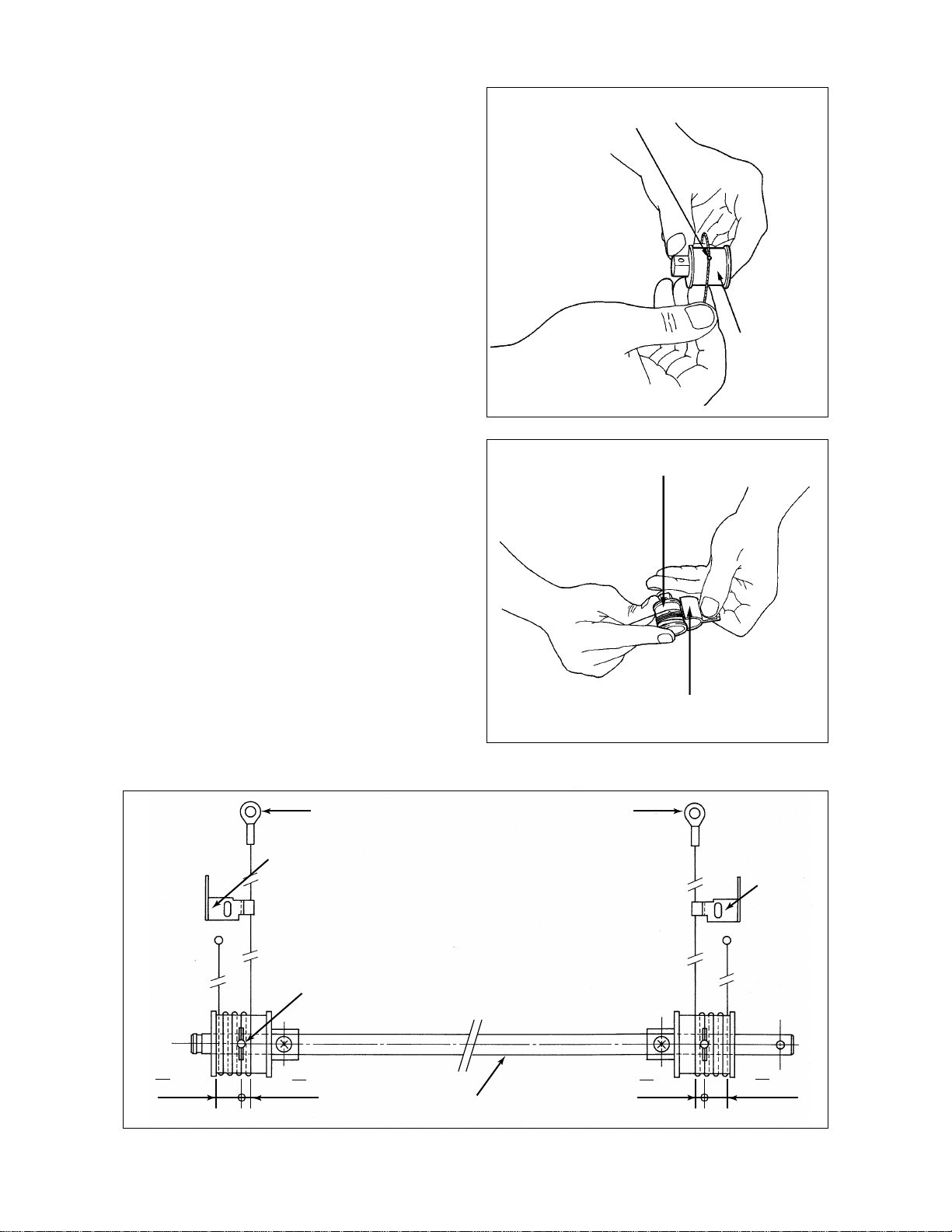
1.16 Adjustment for Scanning Motor Speed, Aligning Amount and Lead Edge Position
Adjustment precedure:
Scanning motor speed
(21)
Note: Normally, Adjustments in the dotted-line boxes are unnecessary.
First of all adjust code 82 because the adjustment amount is based on it.
Aligning amount
Cassette
*(82)→(89)→(81)→(83)→
(PFU cassette (80) optional)
1.16.1 Scanning motor adjustment
(Check and adjustment of the reproduction ratio in
the direction of copy movement)
1. Place a ruler on the glass and make a 100% A4-size copy.
2. Two or three minutes later, compare the copied ruler and the
actual one.
3. If necessary, make adjustment as follows:
Lead edge position
Lead edge position
Cassette~bypass feeding PFU
(53) ~ (56) (57)
Direction of copy paper movement
05
Power
*
Adjust with numeric or zoom keys INTERRUPT
* Larger values make the copy to be enlarged.
21
PRINT
ENERGY SAVER
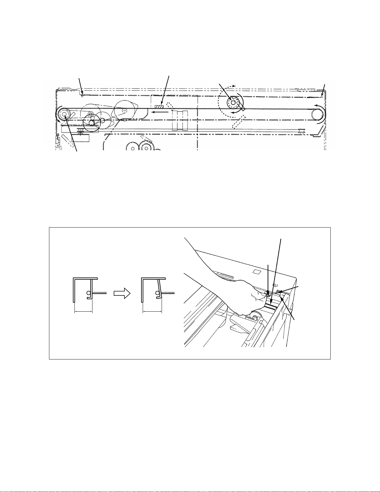
1.16.2 Aligning amount adjustment
If necessary, you can extend the feed roller life by increasing the aligning amount.
<Procedure> (Use codes 82/89/81/83/80 in the test mode “05”)
1.
Code #
05
Power
ENERGY SAVER
82
Cassette
89
81
83
PFU
80
82 INTERRUPT
(Cassette)
Copy size
A3(LD)
A4-R(LT-R)
A4(LT)
B5
A4
PRINT
Test copy
08
(Current value)
09
15
(New set value)
Test copy
1550 ADJUSTMENT
1 - 38
July 1996
®
Oct. 1995 © TOSHIBA CORP.
Page 42

Notes
• There is no need to do this for machines which do not use B5-sized paper.
• There is no need to do this for machines which are equipped with a PFU.
2. Check the copy for any image void and if there is
any, reduce the new value likes “15” → “14” → “13” ...
until no image void occurs. Check for no paper
misfeeding with the new value.
Voiding
50‘ 100 mm
1.16.3 Lead edge adjustment
Since incorrect lead-edge position can also occur due to paper quality, feed roller surface condition,
etc, first check these itmes before starting adjustment.
Note: The lead edge position of each paper source can be adjusted independently. However, if adjustment for
bypass feeding is necessary, make adjustment in order of the cassette → bypass.
Cassette
100% 200% 50%
(53) (54) (55)
Bypass
100%
(56)
PFU cassette
100%
(57)
<Procedure> (Use the appropriate codes in the “05” test mode.)
Example: Adjustment for the cassette (100%)
05
1.
2.
Power
53
PRINT
AJ
ENERGY SAVER
(Example)
11
Test copy for checking
the lead edge position
July 1996
1 - 39Oct. 1995 © TOSHIBA CORP. 1550 ADJUSTMENT
®
Page 43

A = 8 B = 12
Direction of copy paper movement
Document
3. Calculate the new set value:
New value= Current value +
0.8 0.8
66
4.
5.
INTERRUPT
A–B =
AJ
11 +
8–12
= 11–5 = 6
6. Repeat step 2 onward for manual feeding and PFU cassette.
7. Press keys 0 and 9 simultaneously to clear the test mode.
1.17 Registering/Changing ID Codes (Access control mode)
Copy
When ID codes are registered, copies are classified according to each ID code. To make copies, a
registered ID code must be entered using numeric keys.
<Preparation for using the access control mode>
0
8
Power
1550 ADJUSTMENT
7
PRINT
1
INTERRUPT Power OFF
1 - 40
®
July 1996
Oct. 1995 © TOSHIBA CORP.
Page 44

<Registration of the ID code>
• Up to 10 ID codes can be registered. Input a number with three figures.
• Normally, the copier will not start unless one of the ID codes registered is keyed in.
8
PRINT
Power
Input an
ID code
100% Power OFFENERGY SAVER
<Confirmation of the counter value at every code>
• Copy quantity can be recorded at every codes.
• The counter value is 000000 ~ 999999.
8
Power
PRINT
Input an
ID code
PRINT
ZOOM UP
Upper 3 figures
displayed
PRINT
Lower 3 figures
displayed
<ID code list display>
• It is possible to display codes registered in order.
PRINT
8
PRINT
Power
PRINT
Code flashes
<Deletion of the registered ID code>
• Registered codes can be deleted one by one.
8
PRINT
Power
Digital key
Code input
PRINT
ZOOM DOWN
<Change of the counter value>
• The counter value can be changed.
• For example the counter value of 012345 is changed to 123456.
8
PRINT
Power
Input an
ID code
PRINT
ZOOM UP key
Upper 3 figures
displayed
ENERGY SAVER
("---" displayed)
key
Input new
counter
Input new
counter
Completed
value
value
ENERGY SAVER
ENERGY SAVER key
Lower 3 figures
displayed
July 1996
1 - 41Oct. 1995 © TOSHIBA CORP. 1550 ADJUSTMENT
®
Page 45

1.18 User Exposure-Adjustment Mode
This mode allows the user to perform some of the exposure adjustment modes if he desires to do so.
The user can adjust the following three modes:
•Manual exposure 100% (05 mode, code 1)
•Auto exposure 100% (05 mode, code 5)
•Photo exposure 100% (05 mode, code 14)
A. Auto exposure adjustment (AJ5)
(1) Press the auto-exposure key to make the auto-exposure LED to
come on.
(2) While pressing the auto-exposure key, press the ZOOM UP (or
ZOOM DOWN) ke y , and the light MAX (or dark MAX) LED flashes.
(3) Each time the light MAX (or dark MAX) LED flashes, the AJ value
ON
ON
is increased (or decreased) by 2.
(4) When you release one of the keys you pressed simultaneously,
the display goes back to step (1), completing the adjustment.
B. Manual exposure adjustment 100% (AJ1)
(1) Press the auto-exposure key to make the center LED of the manual
exposure to come on.
(2) Steps (2)–(4) are same as for the auto exposure adjustment.
Flashing
ON
ON
ON
Flashing
ON
1550 ADJUSTMENT
1 - 42
Oct. 1995 © TOSHIBA CORP.
Page 46

C. Photo exposure adjustment 100% (AJ14)
(1) Press the PHOTO key to make the photo LED and
the manual exposure center LED to come on.
ON
PHOTO
(2) While pressing the PHOT O ke y, press the ZOOM UP
(or ZOOM DOWN) key, and the light MAX (or dar k
MAX) LED flashes.
(3) Steps (3)–(4) are the same as for the auto exposure
adjustment.
ON
Flashing
ON
1 - 43Oct. 1995 © TOSHIBA CORP. 1550 ADJUSTMENT
Page 47

2. PERIODICAL MAINTENANCE
Inspection every 60,000 copies
(1) Preparation
1) Ask the key operator about the present machine conditions and note them down.
2) Before starting the maintenance work, make and retain a few sample copies for later comparison.
3) Turn off the power switch and disconnect the power cord plug.
(2) The period inspection should be conducted in accordance with the PERIODIC INSPECTION CHECK
LIST shown below . Perform the inspection by ref erring to the figures, as well as to the explanations
in the Service Manual when necessary.
(3) After the inspection has been completed, plug in the machine and turn the power switch on, and
confirm the general operation of the machine by making a few copies and comparing them to those
made previously.
Inspection and over-haul every 180,000 copies
(1) Replace all the cosumables.
(2) Check to see if there is any damage to parts of the drive section (gear, pulley, timing belt, etc.).
Replace parts on principle if damaged.
(3) Check to see if there is any damage or peeling of adhered parts (tape, Mylar, etc.). Replace any
affected parts.
(4) Check to see if all the switches and sensors operate properly. Replace them if the y are not operat-
ing properly.
(5) Clean the inside of the machine thoroughly.
2.1 Periodic Inspection Check List
Symbols used in the Periodic Inspection Check List
Cleaning Lubrication Replacement Date
(A) Cleaning with alcohol (V) Vacuoline (20) Every 20,000 copies Customer’s
(D) Cleaning with a (H) Heavy-medium oil (40) Every 40,000 copies Name
slightly damp cloth (L) Laune 40 (60) Every 60,000 copies Machine
(P) Cleaning with Pit Same thereafter No.
Clean (RC60) Inspector
Cleaning with soft (SI) Silicone oil ( ) Replace in event of
pad, cloth, or cleaner (M) Molytherm deformation or Remarks
(vacuum cleaner) (W) White grease (Molycoat) other damage
Application
2 - 1Oct. 1995 © TOSHIBA CORP. 1550 PERIODICAL MAINTENANCE
Page 48

PERIODIC INSPECTION CHECK LIST
*K=1,000
Section Item to check
Cleaner 1 Entire Unit
2 Main blade ^º *1 (See page 2-6)
3 Toner bag @º Key operator item
4 Recovery blade *2
5 Drum bushings
Drum 10 Drum shaft
11 Drum ^º or more *3
Original 12 Glass A
table
Optical 20 Mirror 1 or A
system
Chargers 40 Charger case
Developer 50 Entire unit
unit
13 Original cover A
21 Mirror 2
22 Mirror 3 or A
23 Mirror 4 or A
24 Mirror 5 or A
25 Mirror 6 or A
26 Slit glass or A (both sides)
27 Reflector or A
28 Lens or A
29 Exposure lamp
30 Auto exposure sensor
31 Reproduction ratio
mechanism (mirrors)
32 Reproduction ratio
mechanism (lens)
33 Sliding sheets
(front/rear)
34 Air filter
35 Ozone filter ^º
41 LED eraser array
42 Charger wire ^º
43 Terminal contact
44 Grid A^º
45 Discharge lamp
51 Developer material ^º *4
52 Rubber seal
Clean at Lubricate at Replace at
60*K copies 60*K copies x *K copies
or A
A
Check while
ON
Remarks
Replace when
heavily stained
Use sandpaper as
required
2 - 2 Oct. 1995 © TOSHIBA CORP.1550 PERIODICAL MAINTENANCE
®
July 1996
Page 49

*K=1,000
Section Item to check
Clean at Lubricate at Replace at
60*K copies 60*K copies x *K copies
Check while
ON
Paper 60 Pick-up roller A
feeding
section
61 Paper feed roller A
62 Separation roller A
63 Aligning roller A`SI *10
64 Paper guide
65 Brush
66 Transport guide section
67 Transport roller (left) A`SI MY-1004 *9
68 Transport roller (right) A`SI MY-1004 *9
Fuser unit 70 Teflon roller (upper) P `⁄¤‚ *5
71
Heat roller entrance guide
P
72 Rubber roller (lower) P `⁄°‚ *6
73 Cleaning felt roller ^º *7
74 Thermistor or P
75
Scrapers (for heat rollers)
P *8
76 Heat roller exit guide P
77 Exit roller A
78 Cleaning blade
Drive
system
80 Drive gear (teeth) `
SI
81 Stad of drive gear `SI
Sorter kit 82 Shaft and bushing `SI *11
Remarks
2 - 3Oct. 1995 © TOSHIBA CORP. 1550 PERIODICAL MAINTENANCE
®July 1996
Page 50

@£
#¡
@¢
@§
%º%¡%™
$¢
!¡
^¢
^¡
^¶
^•
^™
^¡
^™
$º
#º
#£
!£
!™
#¢
@ª
@¶
@∞
$¡
$™$£
12
#™@•
$∞
^º
^£
^∞
5!º
4
3
^§
&¡
&™
&§ &∞
&¶
$™$£
@¡
@º
@™
#∞
&£
&•
&º
2 - 4 Oct. 1995 © TOSHIBA CORP.1550 PERIODICAL MAINTENANCE
&¢
&¶
Page 51

*º
*º*º *º
#™#¡
*º *º
*º*¡
July 1996
2 - 5Oct. 1995 © TOSHIBA CORP. 1550 PERIODICAL MAINTENANCE
®
Page 52

Remarks in the PERIODIC INSPECTION CHECK LIST:
*1.Main blade
If poor cleaning occurs even before the replacement number of copies are made due to the adhesion
of paper dust, etc., since the blade edge may have been damaged, replace the main blade as required. Cleaning the edge with a dry cotton can damage it, so wipe the edge lightly using a soft cloth
soaked with alcohol; be sure to check for no adhesion of cloth fibers.
*2.Recovery blade
If the edge of the recovery blade is damaged, replace the blade.
*3 Drum
Refer to paragraph 3.2.
*4 Developer material
When the developer material is replaced, be sure to check the auto-toner sensor.
*5 Teflon roller
Refer to paragraph 3.5.
*6.Rubber roller
14243
*7.Cleaning felt roller
Refer to paragraph 3.3.
*8.Scraper
Scraper whose tip is damaged should be replaced. If you try to scrape off the toner firmly caked on the
tip forcefully, it may easily be damaged. So replace scrapers if their tip is heavily stained.
*9.Transport roller
When oiling the transport roller, after having disassembled and cleaned the roller, apply a drop of
silicone oil, and then while turning the bushing to spread the oil, insert it.
*10.Aligning roller
After disassembling the upper or lower aligning roller for cleaning, apply one drop of silicone oil to the
inside of the bushing (sliding portion of the aligning roller).
When reassembly has been accomplished, rotate the roller to facilitate the spreading of the oil.
2 - 6 Oct. 1995 © TOSHIBA CORP.1550 PERIODICAL MAINTENANCE
® July 1996
Page 53

*11.Shaft and bushing
After having disassembled and cleaned the sorter kit roller, apply a drop of silicone oil to the shaft and
the shaft interior, reassemble the roller, and then rotate it to spread the oil. This oiling is perf ormed as
a countermeasure to abnormal noise.
Oiling to the shaft
(Silicone oil)
Oiling to the internal surface of
the bushing (Silicone oil)
July 1996
2 - 7Oct. 1995 © TOSHIBA CORP. 1550 PERIODICAL MAINTENANCE
®
Page 54

2.2 Oiling Cycle Table
No.* Item to be oiled Type of oil Number of copies
63 Aligning roller Silicone oil 60
67 Transport roller (left) Silicone oil 60
68 Transport roller (right) Silicone oil 60
80 Drive gears (teeth) Silicone oil 60
81 Stad of drive gear Silicone oil 60
82 Shaft and bushing Silicone oil 60
* Numbers correspond with those in the PERIODIC INSPECTION CHECK LIST.
Note: Do not give any oil to rollers, belts and belt pulleys.
2.3 Supplies/Parts Replacement Schedule
Oiling cycle
x 1000
Replacement cycle
No.* Parts name Code name (Number of copies
2 Main blade PS-BL1550D 60 P17, I34
3 Toner bag PS-TB1550 20 P6, I38
PS-TB1550E
(for Europe)
11 Drum PS-OD1550 60 or more P14, I1
35 Ozone filter — 60 P3, I7
42 Charger wire — 60 P15, I8/P16, I9
44 Grid — 60 P15, I13
51 Developer material PS-ZD1550 60 —
70 Teflon roller (upper) PS-HR1550U 120 P19, I2
72 Rubber roller (lower) PS-HR2510L 180 P20, I5
73 Cleaning felt roller PS-SR1550H 60 P19, I12
* Numbers correspond with those in the PERIODIC INSPECTION CHECK LIST.
** Refer to SERVICE PARTS LIST ED-1550.
2.4 Jig List
Door switch jig **P100, I1
** Refer to SERVICE PARTS LIST ED-1550.
Drum jig **P100, I2
x 1000)
**Parts List
Page/item No.
Wire holder jig **P100, I3
Doctor sleeve jig **P100, I4
2 - 8 Oct. 1995 © TOSHIBA CORP.1550 PERIODICAL MAINTENANCE
®
July 1996
Page 55

3. PRECAUTIONS FOR STORING AND HANDLING SUPPLIES
3.1 Precautions for Storing Toshiba Supplies
A. Toner and Developer
T oner and de veloper should be stored in a place where the ambient temper ature is below 35°C (95°F)
and should also be protected against direct sunlight during transportation.
B. OPC Drum
Similarly to the toner and developer , OPC drums should be stored in a dark place where the ambient
temperature is below 35°C. Be sure to avoid those places where drums may be subjected to high
humidity, chemicals and/or their fumes.
C. Cleaning Blade and Cleaning Felt
These items should be stored in a flat place where the ambient temperature is below 35°C and should
also be protected against high humidity, chemicals and/or their fumes.
D. Heat Roller and Pressure Roller
Avoid those places where heat rollers may be subjected to high humidity, chemicals and/or their
fumes.
E. Copy Paper
Avoid storing copy paper in a place where the humidity is high.
After a package is opened, be sure to place and store it in a storage bag.
3.2 Inspecting and Cleaning OPC Drum
A. Precautions for Handling
(1) Use of gloves
If fingerprints or oils adhere to the drum surface (which degrades the characteristics of the photoconductor), this affects the quality of the copy image; therefore, do not touch the drum surface with
your bare hands.
(2) Removing and reinstalling drums
Since the OPC drum surface is very sensitive, be sure to handle the drum carefully when installing
and removing it so as not damage its surface.
Be sure to apply patting powder (lubricant) to the entire surface of the drum before installing the
drum into the machine.
Notes:
1. Application of the patting powder is to reduce the friction between the drum and cleaning
blade. If the application of patting powder is neglected, the drum and cleaning blade may be
damaged.
2. When paper fibers adhere to the cleaning blade edge, they may reduce the cleaning efficiency and, in addition, may damage the blade and the drum. So, if any fibers are found
adhering to the blade, be sure to remove them carefully using a soft pad.
3 - 1Oct. 1995 © TOSHIBA CORP. 1550 SUPPLIES
Page 56

3. Installation of Machine and Storage of Drum
Avoid installing the machine in such places where it may be subjected to high temperature,
high humidity, chemicals and their fumes.
Do not leave drums in a bright place for a long time, otherwise the drum will fatigue and will
not produce sufficient image density immediately after being installed in the machine.
However, this effect may decrease as time elapses.
4. Cleaning the Drum
At periodic maintenance calls, wipe clean the entire surface of the drum using the designated
cleaning cotton or soft pad. Use sufficiently thick cleaning cotton so as not to scratch the
drum surface inadvertently with your fingertips or nails. Also, remove your ring and wristwatch before starting cleaning work to prevent accidental damage to the drum.
Be sure not to use other organic solvents or silicone oil as they will ha ve an undesirab le effect
on the drum.
5. Repairing Scratches on OPC Surface
If a scratch exists on the OPC surface through which the aluminium substrate can be seen,
no copy image will be produced on this area and, in addition, the cleaning blade will be
damaged so replacement with a new drum will be necessary.
6. Collecting Used OPC Drums
For disposition of used OPC drums, it is recommended to proceed according to the corresponding regional environmental regulations.
3.3 Checking and Replacing Cleaning Felt Roller
(1) Precautions for Handling
Never allow solvents such as thinner, etc. to adhere to the cleaning felt roller.
(2) Poor Heat-Roller Cleaning and Countermeasures
Poor heat-roller cleaning should be judged b y the deposited toner on the roller. When the f elt roller
has heavy toner deposits, the heat-roller surface may be stained with toner. If this happens, replace the cleaning felt roller.
The cleaning felt roller will be gradually degraded due to subjection to the heat from the heat roller
over a long period of time; therefore, replace it preferably after about 60,000 copies have been
made.
3 - 2 Oct. 1995 © TOSHIBA CORP.1550 SUPPLIES
Page 57

3.4 Checking Drum Cleaning Blade
(1) Precautions for Handling
Pay attention to the following points as the cleaning blade life is determined by its edge condition:
1. Do not allow a hard object to hit on or rub against the blade edge. Do not rub the edge with a
cloth.
2. Do not leave oil (or fingerprints, etc.) on the edge.
3. Do not put solvents such as thinner, etc. on the edge.
4. Do not deposit dirt such as paper fibers, etc. on the blade.
5. Do not place the blade near a heat source.
3.5 Checking and Cleaning Upper and Lower Heat Rollers
(1) Precautions for Handling
• Upper Heat Roller
1. Do not leave oil (fingerprints, etc.) on the heat roller.
2. Be extremely careful not to allow a hard object to hit on or rub against the roller because the thin
Teflon layer coated on the alminum substrate is easily damaged and, if damaged, will result in
poor drum cleaning.
• Lower Pressure Roller
1. Do not leave oil (fingerprints, etc.) on the roller surface.
(2) Checking
1. Check for staining and damage to the heat roller and clean or replace if necessary.
2. Clean the separation claws and check for chipped claws.
3. Check cleaning condition of cleaning felt.
4. Check the thermistor for proper contact with the heat roller.
5. Check the fused condition of the toner image.
6. Check the heat rollers for proper rotation.
(3) Cleaning Procedure for Heat Rollers
When the heat roller becomes dirty, it will cause paper jamming. In that case, wipe the roller surface clean with cotton soaked in alcohol or heat-roller cleaner “RC60” which contains silicone oil.
For a better cleaning effect, clean the roller while it is still warm.
Note: Be careful not to rub against the Teflon-coated surface with your fingernails or hard objects
because it is easily damaged. Do not use silicone oil on the upper heat roller.
3 - 3Oct. 1995 © TOSHIBA CORP. 1550 SUPPLIES
Page 58

4. TROUBLESHOOTING
(1)
Optical system initialization errors
C21
1 Turn the power supply ON/OFF, then visually check that the following units are initialized.
C21
Q1: Does the carriage function? (Follow “YES” if the carriage functions e ven slightly, or sounds as
if it is trying to function.)
YES
NO
Check if J11, J82 are correctly connected.
Check if fuse on PS-ACC is connected.
Q2: Is carriage initialization normal?
NO
Check item 2 “Carriage Errors”.
Q3: Is the Service Call message displayed after the lens and mirror move?
YES
NO
Check item 3 “Lens and Mirror Errors”.
Q4: Use the
TEST MODE CH
(0 4) command code 21 or 22 to move the lens and mirror to the
paper-exit position (enlargement position), then turn the power supply ON and OFF again.
When the power is turned ON again, do the lens and/or mirror make an out-of-step noise at
the home position?
NO
YES
For some reason LNS-SW and MRR-SW are not switched ON/
OFF correctly:
●
Check visually if LNS-SW and MRR-SW can clear the bracket.
●
Check for disconnection or short circuiting around pins J80, J81,
J11, J51, J52, J4.
Issue the
TEST MODE CH
command again and visually check
for faulty conditions.
4 - 1Oct. 1995 © TOSHIBA CORP. 1550 TROUBLESHOOTING
Page 59

2 Carriage errors
Remove the glass and move the carriage to the paper-feed end, then turn ON the power supply
and check the following:
Q1: Is there a loud noise after the carriage hits the home position?
NO
YES
Home switch does not come ON.
●
Check that the connector (J58) of the home switch is properly
inserted.
●
Check for disconnection or short-circuiting around J4 to J58.
Q2: Is there a loud noise after the carriage moves slightly or attempts to move?
NO
YES
●
Turn OFF the power supply, and then move the carriage by
hand.
It feels as if there is backlash.
Retighten the setscrews of the scanning motor.
It feels as if the carriage gets caught halfway.
Check if the carriage is getting caught somewhere.
The carriage moves smoothly:
Check if one or more of pins J11-12~17 are disconnected or short-circuiting.
Also check for disconnection or short-circuiting
around IC7, J11-12~17.
4 - 2 Oct. 1995 © TOSHIBA CORP.1550 TROUBLESHOOTING
Page 60

3 Lens and mirror errors
Q1: Are the lens and mirror completely inoperable without any out-of-step noise being heard?
NO
YES
●
Check if J11 is correctly connected.
●
Check if J81, J80 and J83 are correctly connected.
Remove the glass and lens cover.
Press “0” and “4” keys to select
TEST MODE CH
. Using TEST CODE 21 (LNS-MTR), 22 (MRR-
MTR), move the lens motor and mirror motor to check that they operate smoothly.
●
Should it stop halfway as if caught and an out-of-step noise be heard, check the mecha-
nism.
●
The out-of-step noise is heard but there is no movement.
Rotate the motor gears by hand to mov e the mirror or lens slightly, and carry out the
operation test again.
If the out-of step noise is heard again but there is no movement.
LNS-MTR Check for disconnection or short-circuiting around pins 18 through
22 of J11 and J82.
MMR-MTR Check for disconnection or short-circuiting around pins 1 through
5 of J11 and J81, and J79.
4 - 3Oct. 1995 © TOSHIBA CORP. 1550 TROUBLESHOOTING
Page 61

(2)
●
,
C41
Open the rear cover, pull out the power supply plug and check the following:
C43
C44
,
Thermistor disconnection
1 Are any of the connector terminals of J7 and J64 pulled out or discounted?
2 Is either the thermostat of the heater or the heater lamp disconnected?
Check the above, and if necessary carry out repairs.
Then connect digital tester between pins 1 and 6 of J7 on PWA-LGC and turn ON the power
supply.
Q1: Does the heater come ON?
YES
NO
Is the voltage of J7-4, 5 V?
NO: Is the level of pin 1 of IC6 on PWA-LGC, “H”?
NO: Check for disconnection or short-circuiting
in or around Q1, Q3, IC6.
YES: Check for disconnection, short-circuiting
or damage around IC6, J7.
YES: Is the level of pin 11 of J3, “L”?
NO: Check for imperfect contact or disconnec-
tion around 69 of IC10, Q8, Q9, J7 and J3
on PWA-LGC.
YES: Check if there is any terminal of the heater
pulled off, or whether there is a discon-
Check the next question (Q2).
nection or pulled-out connector in harnesses on PS-ACC.
4 - 4 Oct. 1995 © TOSHIBA CORP.1550 TROUBLESHOOTING
Page 62

Q2: Does the voltage displayed on the tester remain at 0 V?
NO
YES
Turn off the main switch and unplug, and disconnect the heater
on PS-ACC.
Turn on the main switch (check that the heater is OFF). After
checking that the fuser unit is hot, check the following:
1 Check that J7-5 is greater than 2.5 V and less than 5V.
2 Check that J7-6 is greater than 0 V and gradually drops
over a period of time.
3 Pull out J7, then test for continuity between 5 and 6 pins
of J7 on harness, to check if the thermistor is disconnected.
4 Check for disconnection or short-circuiting around R7, R8,
R170, R28, R25, R26, R27, R29 on PWA-LGC.
Q3: Does the heater lamp remain ON even when the voltage displayed on the tester rises above
2.5 V?
NO
YES
Turn off the main switch and unplug, and disconnect the heater
on PS-ACC.
Turn on the main switch (check that the heater is OFF). After
checking that the fuser unit is hot, check the following:
1 Check for damage, disconnection or short-circuiting
around IC6, Q1, Q3 on PWA-LGC.
2 With the signal lines harness of the SSR pulled out, does
the heater go OFF when the door switch is forcibly turned
ON and the power supply turned ON? If NO, the SSR
may be damaged. Replace the SSR and check again.
Move the connectors and harnesses of J7 and the relay, and check that the voltage displayed
on the tester does not drop intermittently.
4 - 5Oct. 1995 © TOSHIBA CORP. 1550 TROUBLESHOOTING
Page 63

(3)
●
●
Main motor lock
C01
Using code 1 of
TEST MODE CH
, turn ON the main motor.
Check ON/OFF condition of LED on main motor.
1 When the LED is OFF:
●
Check if the connector of J531 and J532 on main motor is disconnected.
●
Check if fuse on PS-ACC is blown.
2 When the LED is ON and does not flicker:
●
Check that the main motor makes no unusual noise when it rotates.
●
Check for disconnection or short-circuiting around main motor and J10-4, R69, 105, IC1055 on PWA-LGC, and the harness that runs from J10 to main motor.
4 - 6 Oct. 1995 © TOSHIBA CORP.1550 TROUBLESHOOTING
 Loading...