

Page 1
FormNo.3365-305RevC
STX-26StumpGrinder
ModelNo.23210—SerialNo.310000001andUp
ModelNo.23210G—SerialNo.310000001andUp
ToregisteryourproductordownloadanOperator'sManualorPartsCatalogatnocharge,gotowww.T oro.com.OriginalInstructions(EN)
Page 2

WARNING
CALIFORNIA
Proposition65Warning
Thisproductcontainsachemicalorchemicals
knowntotheStateofCaliforniatocausecancer,
birthdefects,orreproductiveharm.
Theengineexhaustfromthisproduct
containschemicalsknowntotheStateof
Californiatocausecancer,birthdefects,
orotherreproductiveharm.
Useofthisproductmaycauseexposureto
chemicalsknowntotheStateofCalifornia
tocausecancer,birthdefects,orother
reproductiveharm.
DANGER
Theremaybeburiedpower,gas,and/ortelephone
linesintheworkarea.Shockorexplosionmay
occurifyoudigintothem.
maintenance,andwarranty.Replacementsmaybe
orderedthroughtheenginemanufacturer.
Havethepropertyorworkareamarkedforburied
linesanddonotdiginmarkedareas.Contactyour
localmarkingserviceorutilitycompanytohavethe
propertymarked(forexample,intheUnitedStates,
call811forthenationwidemarkingservice).
ThissparkignitionsystemcomplieswithCanadian
ICES-002.
Becauseinsomeareastherearelocal,state,orfederal
regulationsrequiringthatasparkarresterbeusedonthe
engineofthismachine,asparkarresterisavailableas
anoption.Ifyourequireasparkarrestor,contactyour
AuthorizedToroServiceDealer.
GenuineTorosparkarrestersareapprovedbytheUSDA
ForestryService.
Important:ItisaviolationofCaliforniaPublic
ResourceCodeSection4442touseoroperate
theengineonanyforest-covered,brush-covered,
orgrass-coveredlandwithoutasparkarrester
mufermaintainedinworkingorder,ortheengine
constricted,equipped,andmaintainedforthe
preventionofre.Otherstatesorfederalareasmay
havesimilarlaws.
Theenclosed
Engine Owner's Man ual
forinformationregardingtheUSEnvironmental
ProtectionAgency(EPA)andtheCalifornia
EmissionControlRegulationofemissionsystems,
©2012—TheT oro®Company
8111LyndaleAvenueSouth
Bloomington,MN55420
issupplied
Contactusatwww.Toro.com.
2
PrintedintheUSA.
AllRightsReserved
Page 3
Introduction
Thismachineisdesignedtogrindandremovetree
stumpsandsurfaceroots.Itisnotintendedtocutrock
oranyothermaterialotherthanwoodandthesoil
aroundastump.
ordeathifyoudonotfollowtherecommended
precautions.
Figure2
Readthisinformationcarefullytolearnhowtooperate
andmaintainyourproductproperlyandtoavoidinjury
andproductdamage.Youareresponsibleforoperating
theproductproperlyandsafely.
YoumaycontactTorodirectlyatwww .Toro.comfor
productandaccessoryinformation,helpndingadealer,
ortoregisteryourproduct.
Wheneveryouneedservice,genuineToroparts,
oradditionalinformation,contactanAuthorized
ServiceDealerorToroCustomerServiceandhave
themodelandserialnumbersofyourproductready.
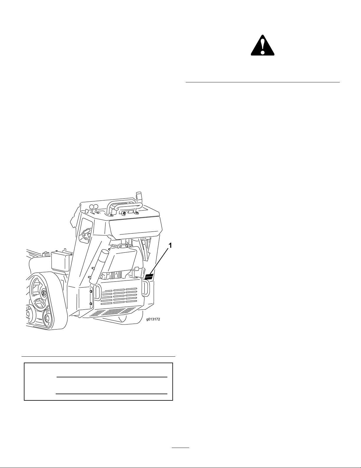
Figure1illustratesthelocationofthemodelandserial
numbersontheproduct.Writethenumbersinthe
spaceprovided.
Figure1
1.Modelandserialnumberplate
ModelNo.
SerialNo.
Thismanualidentiespotentialhazardsandhassafety
messagesidentiedbythesafetyalertsymbol(Figure2),
whichsignalsahazardthatmaycauseseriousinjury
1.Safetyalertsymbol
Thismanualuses2otherwordstohighlightinformation.
Importantcallsattentiontospecialmechanical
informationandNoteemphasizesgeneralinformation
worthyofspecialattention.
Contents
Introduction.................................................................3
Safety...........................................................................4
SafeOperatingPractices.......................................4
SlopeIndicator.....................................................7
SafetyandInstructionalDecals.............................8
Setup.........................................................................11
1InstallingtheGrinderControlLever.................11
2CheckingFluidLevels......................................11
3ChargingtheBattery........................................11
ProductOverview......................................................12
Controls.............................................................12
Specications.....................................................14
Attachments/Accessories...................................14
Operation...................................................................15
AddingFuel.......................................................15
CheckingtheEngineOilLevel............................16
CheckingtheHydraulicFluidLevel.....................16
StartingandStoppingtheEngine........................17
StoppingtheMachine.........................................18
MovingaNon-functioningMachine...................18
GrindingaStump...............................................18
SecuringtheMachineforTransport....................19
LiftingtheMachine............................................19
OperatingTips...................................................19
Maintenance...............................................................21
RecommendedMaintenanceSchedule(s)................21
PremaintenanceProcedures....................................21
RemovingtheCoverPlate...................................22
InstallingtheCoverPlate....................................22
RemovingtheBottomShield..............................22
InstallingtheBottomShield................................22
Lubrication.............................................................23
GreasingtheMachine.........................................23
EngineMaintenance...............................................23
ServicingtheAirCleaner....................................23
ServicingtheEngineOil.....................................24
3
Page 4

ServicingtheSparkPlug.....................................25
FuelSystemMaintenance.......................................27
DrainingtheFuelTank.......................................27
ReplacingtheFuelFilter.....................................27
ElectricalSystemMaintenance................................28
ServicingtheBattery...........................................28
ReplacingtheFuses............................................30
DriveSystemMaintenance.....................................30
ServicingtheTracks............................................30
BeltMaintenance....................................................33
ReplacingthePumpDriveBelt...........................33
ControlsSystemMaintenance.................................33
AdjustingtheTractionControl
Alignment......................................................33
AdjustingtheTractionControlNeutral
Position..........................................................35
AdjustingtheTrackingoftheTraction
Control,FullForwardPosition........................35
HydraulicSystemMaintenance...............................35
ReplacingtheHydraulicFilter.............................35
ChangingtheHydraulicFluid.............................35
CheckingtheHydraulicLines.............................37
GrinderMaintenance..............................................37
ReplacingtheTeeth............................................37
Cleaning.................................................................38
RemovingDebrisfromtheMachine....................38
Storage.......................................................................38
Troubleshooting.........................................................40
Schematics.................................................................41
Safety
Improperuseormaintenancebytheoperatoror
ownercanresultininjury.T oreducethepotential
forinjury,complywiththesesafetyinstructions
andalwayspayattentiontothesafetyalert
symbol
Danger
complywiththeinstructionmayresultinpersonal
injuryordeath.
,whichmeans:
—personalsafetyinstruction.Failureto
SafeOperatingPractices
Thisproductiscapableofamputatinghandsandfeet.
Alwaysfollowallsafetyinstructionstoavoidserious
injuryordeath.
WARNING
Engineexhaustcontainscarbonmonoxide,an
odorless,deadlypoisonthatcankillyou.
Donotruntheengineindoorsorinanenclosed
area.
Training
•ReadtheOperator'sManualandothertraining
material.Iftheoperator(s)ormechanic(s)cannot
readEnglish,itistheowner'sresponsibilityto
explainthismaterialtothem.
•Becomefamiliarwiththesafeoperationofthe
equipment,operatorcontrols,andsafetysigns.
•Alloperatorsandmechanicsshouldbetrained.The
ownerisresponsiblefortrainingtheusers.
•Neverletchildrenoruntrainedpeopleoperateor
servicetheequipment.Localregulationsmayrestrict
theageoftheoperator.
•Theowner/usercanpreventandisresponsiblefor
accidentsorinjuriesoccurringtohimselforherself,
otherpeopleorproperty.
Caution
,
W ar ning
,or
Preparation
•Evaluatetheterraintodeterminewhataccessories
andattachmentsareneededtoproperlyand
safelyperformthejob.Onlyuseaccessoriesand
attachmentsapprovedbythemanufacturer.
•Wearappropriateclothingincludinghardhat,
safetyglasses,longpants,safetyshoes,andhearing
protection.Longhair,looseclothingorjewelrymay
gettangledinmovingparts.
•Inspecttheareawheretheequipmentistobeused
andremoveallobjectssuchasrocks,toys,andwire
whichcanbethrownbythemachine.
4
Page 5

•Useextracarewhenhandlinggasolineandother
fuels.Theyareammableandvaporsareexplosive.
–Useonlyanapprovedcontainer
–Neverremovethegascaporaddfuelwiththe
enginerunning.Allowtheenginetocoolbefore
refueling.Donotsmoke.
–Neverrefuelordrainthemachineindoors.
•Checkthattheoperatorpresencecontrols,safety
switches,andshieldsareattachedandfunctioning
properly.Donotoperateunlesstheyarefunctioning
properly.
Operation
•Neverrunanengineinanenclosedarea.
•Onlyoperateingoodlight,keepingawayfromholes
andhiddenhazards.
•Besurealldrivesareinneutralbeforestartingthe
engine.Onlystarttheenginefromtheoperator's
position.
•Slowdownanduseextracareonhillsides.Besure
totravelintherecommendeddirectiononhillsides.
Turfconditionscanaffectthemachine'sstability.
•Slowdownandusecautionwhenmakingturnsand
whenchangingdirectionsonslopes.
•Neveroperatewiththeguardsnotsecurelyinplace.
Besureallinterlocksareattached,adjustedproperly ,
andfunctioningproperly .
•Donotchangetheenginegovernorsettingor
overspeedtheengine.
•Stoponlevelground,lowerthegrinder,disengage
thehydraulics,andshutofftheenginebeforeleaving
theoperator'spositionforanyreason.
•Keephandsandfeetawayfromthemovinggrinder
wheelandteeth.
•Lookbehindanddownbeforebackinguptobesure
ofaclearpath.
•Nevercarrypassengersandkeeppetsandbystanders
away.
•Slowdownandusecautionwhenmakingturnsand
crossingroadsandsidewalks.
•Donotoperatethemachineundertheinuenceof
alcoholordrugs.
•Usecarewhenloadingorunloadingthemachine
intoatrailerortruck.
•Usecarewhenapproachingblindcorners,shrubs,
trees,orotherobjectsthatmayobscurevision.
•Ensurethattheareaisclearofotherpeoplebefore
operatingthemachine.Stopthemachineifanyone
entersthearea.
•Neverleavearunningmachineunattended.Always
lowerthegrinder,stoptheengine,andremovethe
keybeforeleaving.
•Neverjerkthecontrols;useasteadymotion.
•Watchfortrafcwhenoperatingnearorcrossing
roadways.
•Donottouchpartswhichmaybehotfrom
operation.Allowthemtocoolbeforeattemptingto
maintain,adjust,orservice.
•Ensurethatyouoperatethemachineinareaswhere
therearenoobstaclesincloseproximitytothe
operator.Failuretomaintainadequatedistancefrom
trees,walls,andotherbarriersmayresultininjury
asthemachinebacksupduringoperationifthe
operatorisnotattentivetothesurroundings.Only
operatetheunitinareaswherethereissufcient
clearancefortheoperatortosafelymaneuverthe
product.
•Beforedigging,havetheareamarkedfor
undergroundutilities,anddonotdiginmarkedareas.
•Locatethepinchpointareasmarkedonthemachine
andkeephandsandfeetawayfromtheseareas.
•Lightningcancausesevereinjuryordeath.If
lightningisseenorthunderisheardinthearea,do
notoperatethemachine;seekshelter.
SlopeOperation
Slopesareamajorfactorrelatedtoloss-of-controland
tip-overaccidents,whichcanresultinsevereinjuryor
death.Allslopesrequireextracaution.
•Donotoperatethemachineonhillsidesorslopes
exceedingtheanglesrecommendedinthefollowing
table.
FrontFacing
Uphill
12°18°16°
Note:SeealsotheSlopeIndicator(page7).
•Operateupanddownslopeswiththefrontend
ofthemachineuphill.
•Removeobstaclessuchasrocks,treelimbs,etc.
fromtheworkarea.Watchforholes,ruts,orbumps,
asuneventerraincouldoverturnthemachine.Tall
grasscanhideobstacles.
•UseonlyToro-approvedaccessories.Accessoriescan
changethestabilityandtheoperatingcharacteristics
ofthemachine.Warrantymaybevoidedifusedwith
unapprovedaccessories.
•Keepallmovementsonslopesslowandgradual.Do
notmakesuddenchangesinspeedordirection.
RearFacingUphill
SideFacingUphill
5
Page 6

•Avoidstartingorstoppingonaslope.Ifthemachine
losestraction,proceedslowly,straightdownthe
slope.
•Avoidturningonslopes.Ifyoumustturn,turn
slowlyandkeeptheheavyendofthemachineuphill.
•Donotoperateneardrop-offs,ditches,or
embankments.Themachinecouldsuddenlyturn
overifatrackgoesovertheedgeofaclifforditch,
orifanedgecavesin.
•Donotoperateonwetgrass.Reducedtractioncould
causesliding.
•Donotparkthemachineonahillsideorslope
withoutloweringthegrindertothegroundand
chockingthetracks.
MaintenanceandStorage
•Disengagethehydraulics,lowerthegrinder,stopthe
engine,andremovethekey.W aitforallmovement
tostopbeforeadjusting,cleaning,orrepairing.
•Cleandebrisfromthegrinder,drives,mufers,and
enginetohelppreventres.Cleanupoilorfuel
spillage.
•Lettheenginecoolbeforestoringanddonotstore
nearame.
•Donotstorefuelnearamesordrainindoors.
•Parkthemachineonlevelground.Neverallow
untrainedpersonneltoservicethemachine.
•Usejackstandstosupportcomponentswhen
required.
•Carefullyreleasepressurefromcomponentswith
storedenergy.
•Disconnectthebatteryorremovethesparkplug
wiresbeforemakinganyrepairs.Disconnect
thenegativeterminalrstandthepositivelast.
Reconnectpositiverstandnegativelast.
•Keephandsandfeetawayfrommovingparts.If
possible,donotmakeadjustmentswiththeengine
running.
•Keepallpartsingoodworkingconditionandall
hardwaretightened.Replaceallwornordamaged
decals.
•Useextracarewhenhandlinggasolineandother
fuels.Theyareammableandvaporsareexplosive.
–Useonlyanapprovedcontainer.
–Neverremovethegascaporaddfuelwhen
theengineisrunning.Allowtheenginetocool
beforerefueling.Donotsmoke.
–Neverrefuelthemachineindoors.
–Neverstorethemachineorfuelcontainerinside
wherethereisanopename,suchasneara
waterheaterorfurnace.
–Neverllacontainerwhileitisinsideavehicle,
trunk,pick-upbed,oranysurfaceotherthanthe
ground.
–Keepcontainernozzleincontactwiththetank
duringlling.
•Stopandinspecttheequipmentifyoustrikean
object.Makeanynecessaryrepairsbeforerestarting.
•UseonlygenuineTororeplacementpartstoensure
thatoriginalstandardsaremaintained.
•Batterysafety:
–Chargebatteriesinanopen,wellventilated
area,awayfromsparkandames.Unplugthe
chargerbeforeconnectingordisconnectingit
fromthebattery.W earprotectiveclothingand
useinsulatedtools.
–Batteryacidispoisonousandcancauseburns.
Avoidcontactwithskin,eyes,andclothing.
Protectyourface,eyes,andclothingwhen
workingwithabattery.
–Batterygasescanexplode.Keepcigarettes,
sparksandamesawayfromthebattery.
•Keepyourbodyandhandsawayfrompinhole
leaksornozzlesthatejecthighpressurehydraulic
uid.Usecardboardorpapertondhydraulic
leaks;neveruseyourhands.Hydraulicuidescaping
underpressurecanpenetrateskinandcauseinjury
requiringsurgerywithinafewhoursbyaqualied
surgeonorgangrenemayresult.
•Keepnutsandboltstight.Keepequipmentingood
condition.
•Nevertamperwithsafetydevices.
•Keepthemachinefreeofgrass,leaves,orother
debrisbuild-up.Cleanupoilorfuelspillage.Allow
themachinetocoolbeforestoring.
6
Page 7
SlopeIndicator
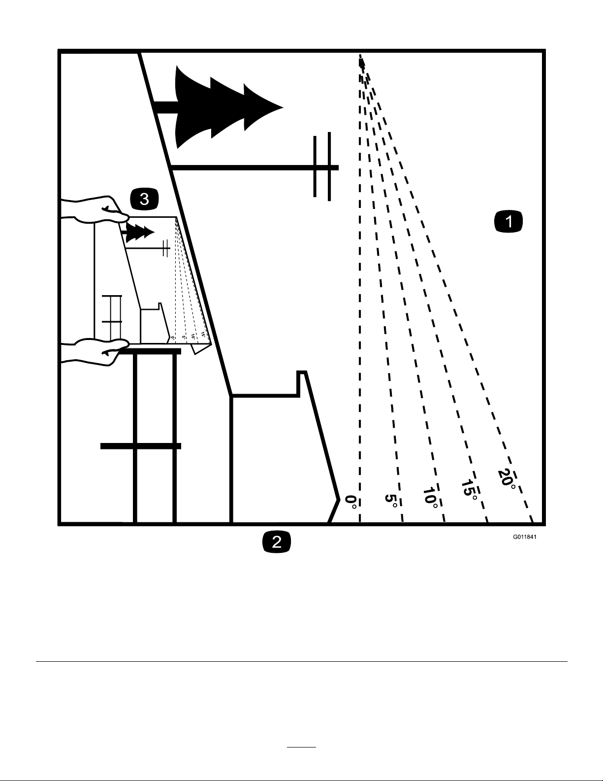
G011841
Figure3
Thispagemaybecopiedforpersonaluse.
1.Todeterminethemaximumslopeyoucansafelyoperatethemachineon,refertoSlopeOperation(page5).Usetheslope
indicatortodeterminethedegreeofslopeofhillsbeforeoperating.Donotoperatethismachineonaslopegreaterthanthat
speciedinSlopeOperation(page5).Foldalongtheappropriatelinetomatchtherecommendedslope.
2.Alignthisedgewithaverticalsurface,atree,building,fencepole,etc.
3.Exampleofhowtocompareslopewithfoldededge.
7
Page 8
SafetyandInstructionalDecals
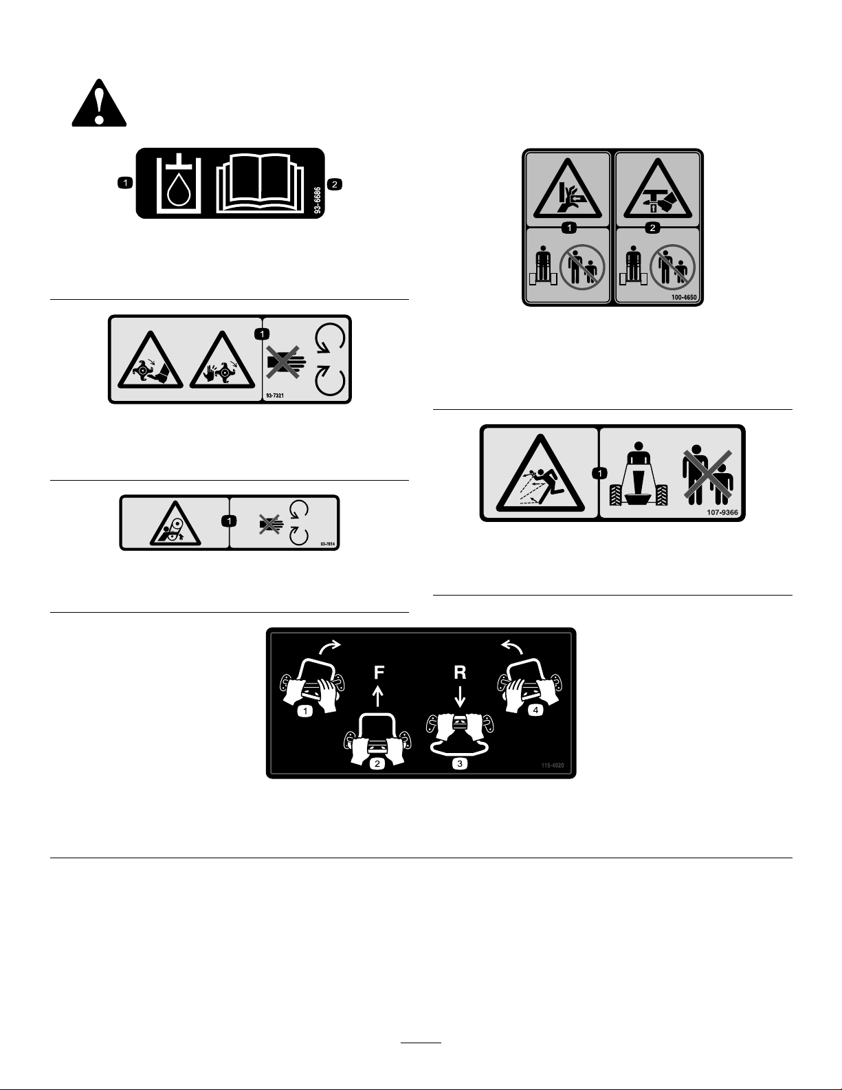
Safetydecalsandinstructionsareeasilyvisibletotheoperatorandarelocatednearanyareaof
potentialdanger.Replaceanydecalthatisdamagedorlost.
93-6686
1.Hydraulicoil
2.ReadtheOperator'sManual.
93-7321
1.Cutting/dismembermenthazardofhandsandfeet,rotating
knives/blades—stayawayfrommovingparts.
100-4650
1.Crushinghazardofhand—keepbystandersasafedistance
fromthemachine.
2.Crushinghazardoffoot—keepbystandersasafedistance
fromthemachine.
93-7814
1.Entanglementhazard,belt—stayawayfrommovingparts.
115-4020
1.Turnright3.Reverse
2.Forward
107-9366
1.Thrownobjecthazard—keepbystandersasafedistance
fromthemachine.
4.Turnleft
8
Page 9
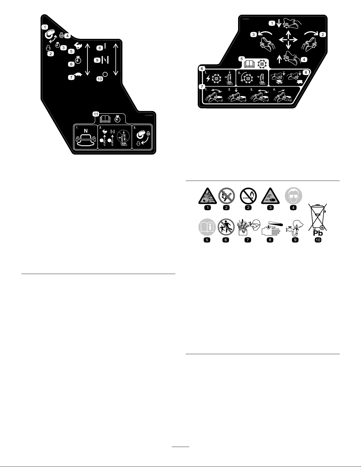
119-4560
1.Ignitionkey
2.Engine—start
3.Engine—run
4.Engine—stop
5.Fast
6.Enginespeed
7.Slow
8.On/Closed
9.Choke
10.Off/Open
11.ReadtheOperator'sManualbeforestartingtheengine;
placethetractioncontrolinNeutral,movetheenginespeed
toFastandthechoketoOn/Closed,turntheignitionkey
torun.
119-4561
1.ReadtheOperator'sManualbeforeoperatingthecutter;
engagethesideleverandtopbuttonofthejoystickto
startthecutterblade;continueengagingthesideleverto
maintaincutterrotation.
2.Lowerthecutterhead
3.Pivotthecutterheadtotheright
4.Raisethecutterhead
5.Pivotthecutterheadtotheleft
BatterySymbols
Someorallofthesesymbolsareonyourbattery
1.Explosionhazard
2.Nore,opename,or
smoking.
3.Causticliquid/chemical
burnhazard
4.Weareyeprotection9.Flusheyesimmediately
5.ReadtheOperator's
Manual.
6.Keepbystandersasafe
distancefromthebattery.
7.Weareyeprotection;
explosivegasescan
causeblindnessandother
injuries
8.Batteryacidcancause
blindnessorsevereburns.
withwaterandgetmedical
helpfast.
10.Containslead;donot
discard.
9
Page 10
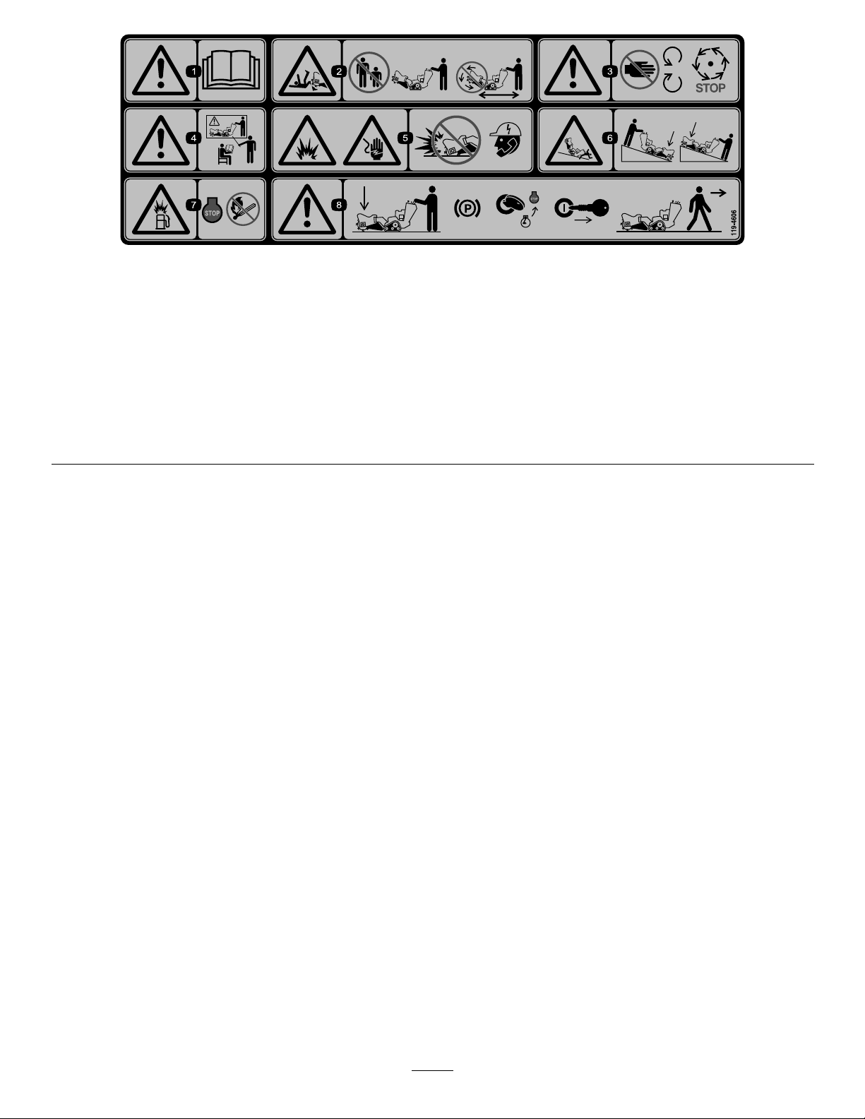
119-4606
1.Warning—readtheOperator'sManual.
2.Cutting/dismembermenthazard;cutter—keepbystandersa
safedistancefromthemachine;donotoperatethecutter
headwhiletransportingthemachine.
3.Warning—stayawayfrommovingparts;waitforallmoving
partstostop.
4.Warning—donotoperatethismachineunlessyouaretrained.
5.Explosionandelectricshockhazard—donotdiginareaswith
buriedutilitylines;contactlocalpowerorganizationsbefore
digging.
6.Tipping/crushinghazard—lowerthecutterheadwhen
operatingonslopes.
7.Explosionhazard,fueling—stoptheengineandextinguish
allameswhenfueling.
8.Warning—lowerthecutterhead,settheparkingbrake(if
applicable),stoptheengine,removetheignitionkeybefore
leavingthemachine.
10
Page 11
Setup
LooseParts
Usethechartbelowtoverifythatallpartshavebeenshipped.
ProcedureDescription
Grindercontrollever
1
2
3
Jamnut1
Nopartsrequired
Nopartsrequired
1
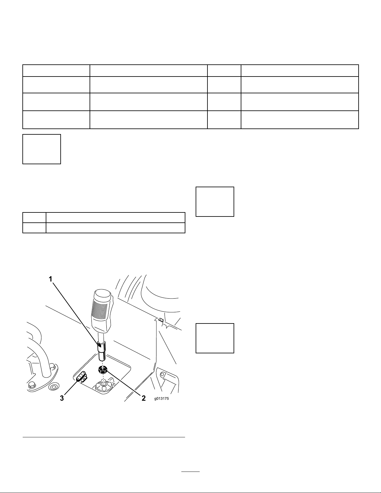
InstallingtheGrinderControl
Lever
Partsneededforthisprocedure:
1
Grindercontrollever
1Jamnut
Procedure
1.Threadthejamnutontothegrindercontrollever
(Figure4).
Qty.
1
–
–
3.Withthetriggerorientedforward,tightenthejam
nutagainstthereceptacletosecuretheleverinplace
(Figure4).
4.Connectthewireonthelevertothe4-pinconnector
underthecontrolpanel(
Installthegrindercontrollever.
Checktheuidlevels.
Chargethebattery.
Use
Figure4).
2
CheckingFluidLevels
NoPartsRequired
Procedure
Figure4
1.Grindercontrollever
2.Jamnut
2.Threadthegrindercontrolleverintotherecepticle
onthecontrolpanel(Figure4).
3.4-pinconnector
Beforestartingtheengineforthersttime,check
theengineoilandhydraulicuidlevels;referto
CheckingtheEngineOilLevel(page16)and
CheckingtheHydraulicFluidLevel(page16)formore
information.
3
ChargingtheBattery
NoPartsRequired
Procedure
Chargethebattery;referto
ChargingtheBattery(page29)formoreinformation.
11
Page 12
ProductOverview
ChokeLever
Beforestartingacoldengine,movethechokelever
forward.Aftertheenginestarts,regulatethechoketo
keeptheenginerunningsmoothly.Assoonaspossible,
movethechokeleverallthewayrearward.
Note:Awarmenginerequireslittleornochoking.
HourMeter
Whentheengineisoff,thehourmeterdisplaysthe
numberofhoursofoperationthathavebeenlogged
onthemachine.
ReferenceBar
Whendrivingthemachine,usethereferencebarasa
handleandaleveragepointforcontrollingthetraction
control.Toensuresmooth,controlledoperation,donot
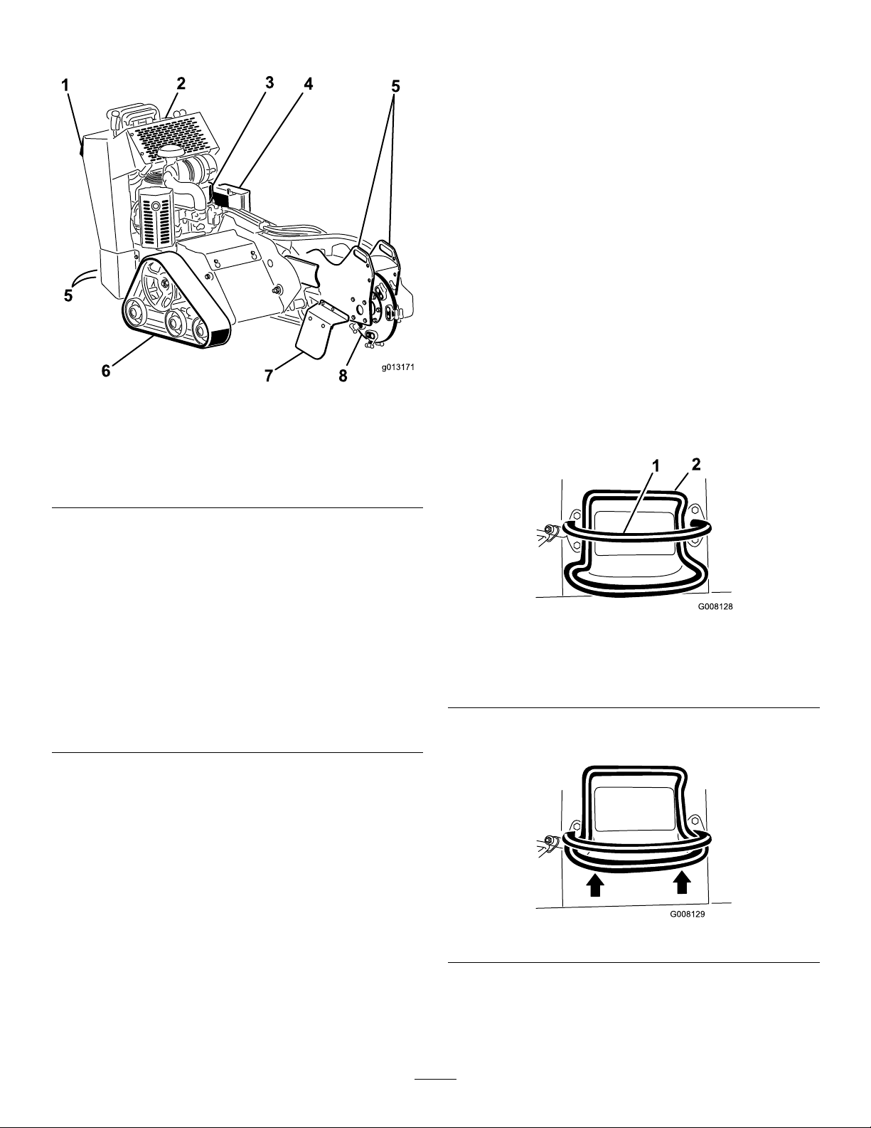
Figure5
1.Reverse
safety
plate
2.Control
panel
3.Engine
4.Battery6.Track
5.Tie-down/
liftpoint
7.Chip
shield
8.Grinder
takebothhandsoffofthereferencebarwhileoperating
themachine.
TractionControl
Controls
Becomefamiliarwithallthecontrols(Figure6)before
youstarttheengineandoperatethemachine.
Figure6
1.Keyswitch5.Tractioncontrol
2.Throttlelever
3.Chokelever7.Grindercontrollever
4.Hourmeter
KeySwitch
Thekeyswitchhasthreepositions:off,run,andstart.
Tostarttheengine,rotatethekeytothestartposition.
Releasethekeywhenenginestartsanditwillmove
automaticallytotherunposition.
Tostoptheengine,rotatethekeytotheoffposition.
ThrottleLever
Movethecontrolforwardtoincreasetheenginespeed
andrearwardtodecreasespeed.
6.Referencebar
Figure7
1.Referencebar(doesnotmovetogiveyouareferencepoint
andaxedhandletoholdwhileoperatingthetractionunit)
2.Tractioncontrol(movestocontrolthemachine)
•Tomoveforward,movethetractioncontrolforward
Figure8).
(
Figure8
•Tomoverearward,movethetractioncontrol
rearward(Figure9).Whenreversing,lookbehind
forobstructionsandkeepyourhandsonthe
referencebar(Figure7).
12
Page 13
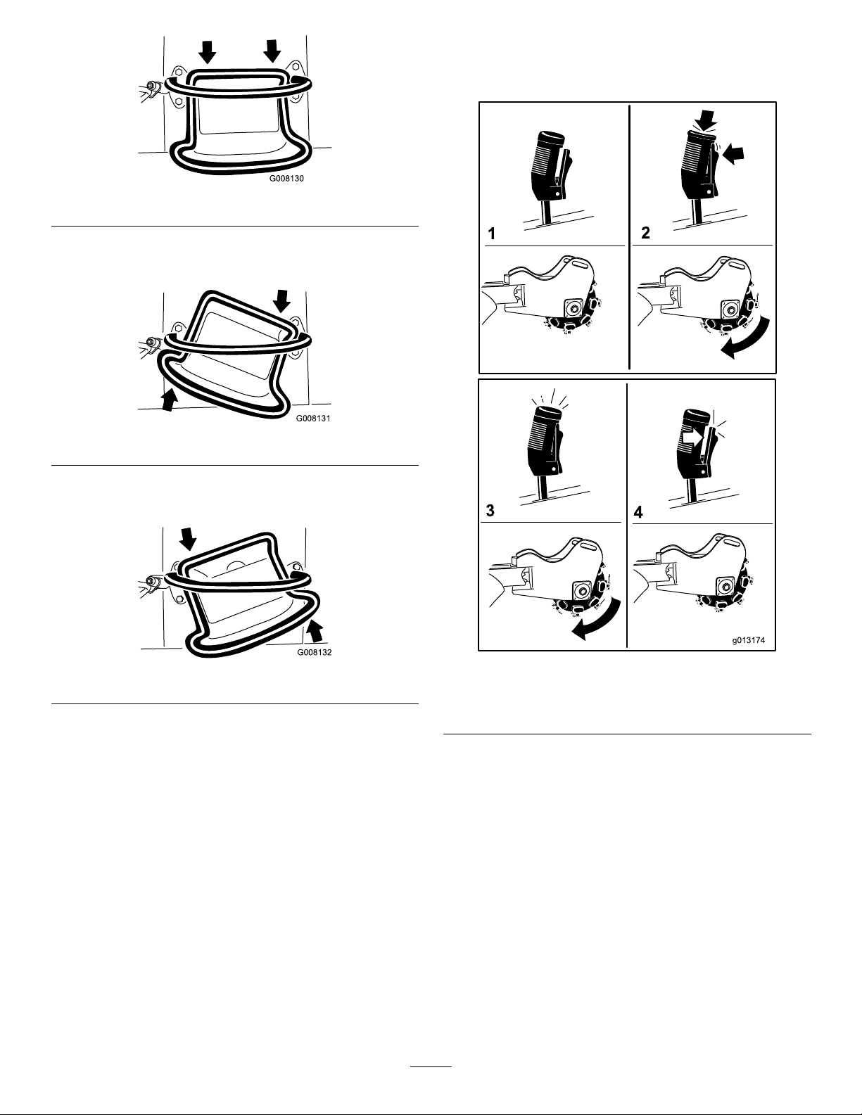
Figure9
G008131
G008132
•Toturnright,rotatethetractioncontrolclockwise
(Figure10).
Figure10
Note:Ifyouareoperatingthegrinderan
momentarilyreleasethetrigger(i.e.,lessthanahalf
second)thegrinderwillcontinueoperation.
•Toturnleft,rotatethetractioncontrol
counterclockwise(Figure11).
Figure11
•Tostop,releasethetractioncontrol(Figure7).
Note:Thefartheryoumovethetractioncontrolin
anydirection,thefasterthemachinewillmoveinthat
direction.
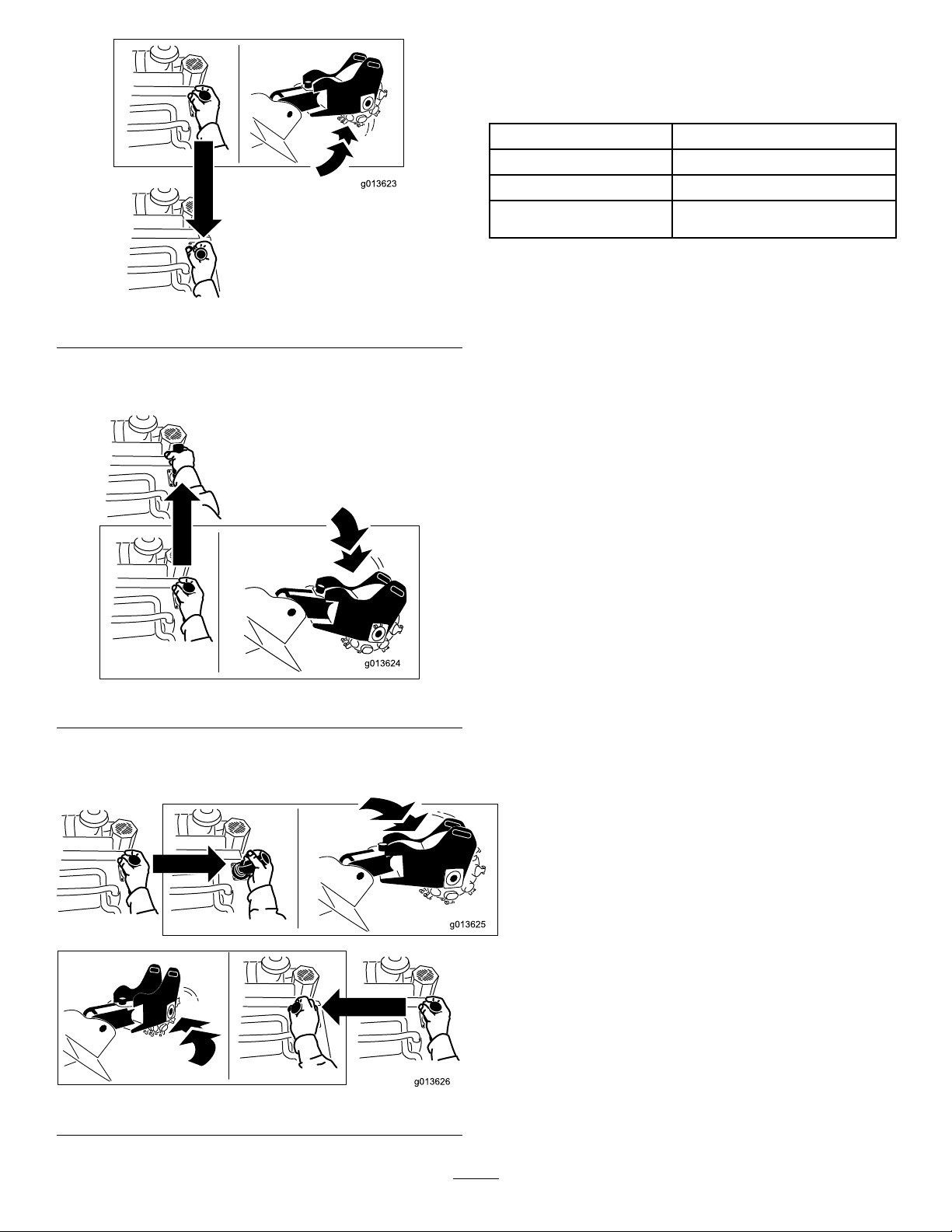
GrinderControlLever
Operatethegrinderusingthegrindercontrolleveras
follows:
Figure12
1.Neutral3.Runthegrinder
2.Startthegrinder4.Stopthegrinder
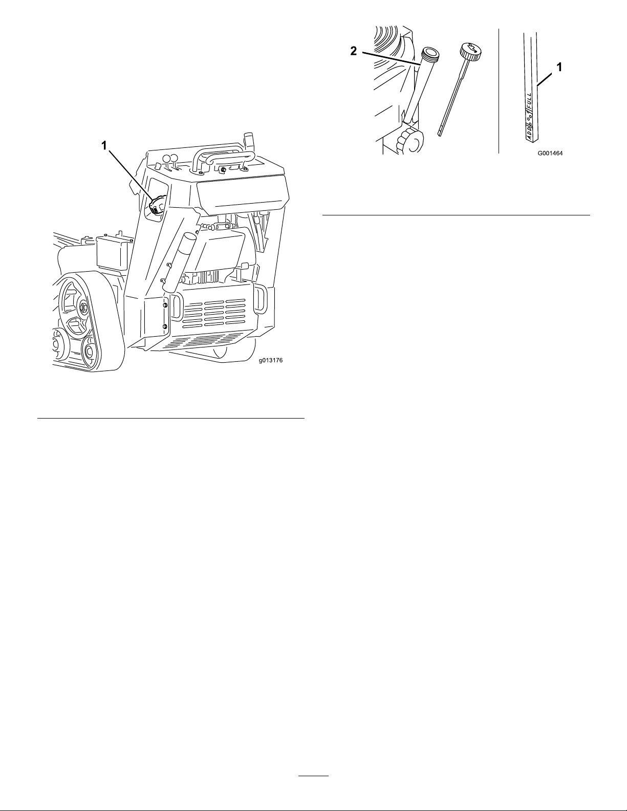
•Toraisethegrinder,pullbackonthelever
(Figure13).
•Tostartthegrinder(Figure12),presstheredbutton
onthetopofthelever,thensqueezethetrigger.
Oncethegrinderhasstarted,youcanreleasethe
redbutton.
•Tostopthegrinder(Figure12),releasethetrigger
formorethanahalfsecond.
13
Page 14
Specications
Note:Specicationsanddesignaresubjecttochange
withoutnotice.
Figure13
•Tolowerthegrinder,pushtheleverforward
Figure14).
(
Width
Length
Height
Weight
33.15inches(84.2cm)
78.15inches(198.5cm)
44.61inches(1 13.3cm)
1200lb(544Kg)
Attachments/Accessories
AselectionofToroapprovedattachmentsand
accessoriesareavailableforusewiththemachineto
enhanceandexpanditscapabilities.Contactyour
AuthorizedServiceDealerorDistributororgoto
www.Toro.comforalistofallapprovedattachments
andaccessories.
Figure14
•Torotatethegrindertotherightorleft,movethe
leverinthedesireddirection.
Figure15
14
Page 15

Operation
Note:Determinetheleftandrightsidesofthe
machinefromthenormaloperatingposition.
Important:Beforeoperating,checkthefueland
oillevel,andremovedebrisfromthemachine.
Also,ensurethattheareaisclearofpeopleand
debris.Youshouldalsoknowandhavemarkedthe
locationsofallutilitylines.
AddingFuel
Useunleadedgasoline(87pumpoctaneminimum).
Leaded,regulargasolinemaybeusedifunleadedisnot
available.
DANGER
Incertainconditions,gasolineisextremely
ammableandhighlyexplosive.Areorexplosion
fromgasolinecanburnyouandothersandcan
damageproperty.
•Fillthefueltankoutdoors,inanopenarea,
whentheengineiscold.Wipeupanygasoline
thatspills.
•Neverllthefueltankinsideanenclosedtrailer.
•Donotllthefueltankcompletelyfull.Add
gasolinetothefueltankuntilthelevelis1/4to
1/2inch(6to13mm)belowthebottomofthe
llerneck.Thisemptyspaceinthetankallows
gasolinetoexpand.
•Neversmokewhenhandlinggasoline,andstay
awayfromanopenameorwheregasoline
fumesmaybeignitedbyaspark.
•Storegasolineinanapprovedcontainerand
keepitoutofthereachofchildren.Neverbuy
morethana30-daysupplyofgasoline.
•Donotoperatewithoutentireexhaustsystem
inplaceandinproperworkingcondition.
DANGER
Incertainconditionsduringfueling,static
electricitycanbereleasedcausingasparkwhich
canignitethegasolinevapors.Areorexplosion
fromgasolinecanburnyouandothersandcan
damageproperty.
•Alwaysplacegasolinecontainersontheground
awayfromyourvehiclebeforelling.
•Donotllgasolinecontainersinsideavehicle
oronatruckortrailerbedbecauseinterior
carpetsorplastictruckbedlinersmayinsulate
thecontainerandslowthelossofanystatic
charge.
•Whenpractical,removegas-powered
equipmentfromthetruckortrailerandrefuel
theequipmentwithitswheelsontheground.
•Ifthisisnotpossible,thenrefuelsuch
equipmentonatruckortrailerfromaportable
container,ratherthanfromagasolinedispenser
nozzle.
•Ifagasolinedispensernozzlemustbeused,
keepthenozzleincontactwiththerimofthe
fueltankorcontaineropeningatalltimesuntil
fuelingiscomplete.
Important:Donotusemethanol,gasoline
containingmethanol,orgasoholcontainingmore
than10%ethanolbecausethefuelsystemcouldbe
damaged.Donotmixoilwithgasoline.
UsingStabilizer/Conditioner
Useafuelstabilizer/conditionerinthemachineto
providethefollowingbenets:
•Keepsgasolinefreshduringstorageof90daysor
less.Forlongerstorageitisrecommendedthatthe
fueltankbedrained.
•Cleanstheenginewhileitruns
•Eliminatesgum-likevarnishbuildupinthefuel
system,whichcauseshardstarting
Important:Donotusefueladditivescontaining
methanolorethanol.
Addthecorrectamountofgasstabilizer/conditioner
tothegas.
Note:Afuelstabilizer/conditionerismosteffective
whenmixedwithfreshgasoline.Tominimizethe
chanceofvarnishdepositsinthefuelsystem,usefuel
stabilizeratalltimes.
15
Page 16
FillingtheFuelTank
1.Parkthemachineonalevelsurface,lowerthe
grinder,andstoptheengine.
2.Removethekeyandallowtheenginetocool.
3.Cleanaroundthefueltankcapandremoveit
Figure16).
(
Figure17
Figure16
1.Fueltankcap
4.Addunleadedgasolinetothefueltank,untilthe
levelis1/4to1/2inchbelowthebottomofthe
llerneck.
1.Oilllerhole
2.Oildipstick
3.Fullmark
4.Addmark
4.Removethedipstickandwipetheendclean
(Figure17).
5.Slidethedipstickfullyintothedipsticktubewithout
threadingitintothellerneck(Figure17).
6.Pullthedipstickoutandlookattheend.The
oilshouldbebetweentheAddandFullmarks
Figure17).
(
7.IftheoilisbelowtheAddmark,add10w30engine
oiltothellerhole,checkingthelevelfrequently
withthedipstick,untiltheoillevelreachestheFull
mark.
8.Replacethedipstick.
CheckingtheHydraulicFluid
Level
Important:Thisspaceinthetankallows
gasolinetoexpand.Donotllthefueltank
completelyfull.
5.Installthefueltankcapsecurely .
6.Wipeupanygasolinethatmayhavespilled.
CheckingtheEngineOilLevel
ServiceInterval:Beforeeachuseordaily
1.Parkthemachineonalevelsurface,lowerthe
grinder,andstoptheengine.
2.Removethekeyandallowtheenginetocool.
3.Cleanaroundtheoildipstick(
Figure17).
ServiceInterval:Every25hours
HydraulicTankCapacity:6USgallons(23l)
RefertoChangingtheHydraulicFluid(page35)for
hydraulicuidspecications.
1.Parkthemachineonalevelsurfaceandlowerthe
grinder.
2.Stoptheengine,removethekey,andallowthe
enginetocool.
3.Lookintotheglassbubbleontherightsideofthe
machine.Ifyoucannotseehydraulicuidinthe
bubble,continuethisproceduretoadduid.
16
Page 17
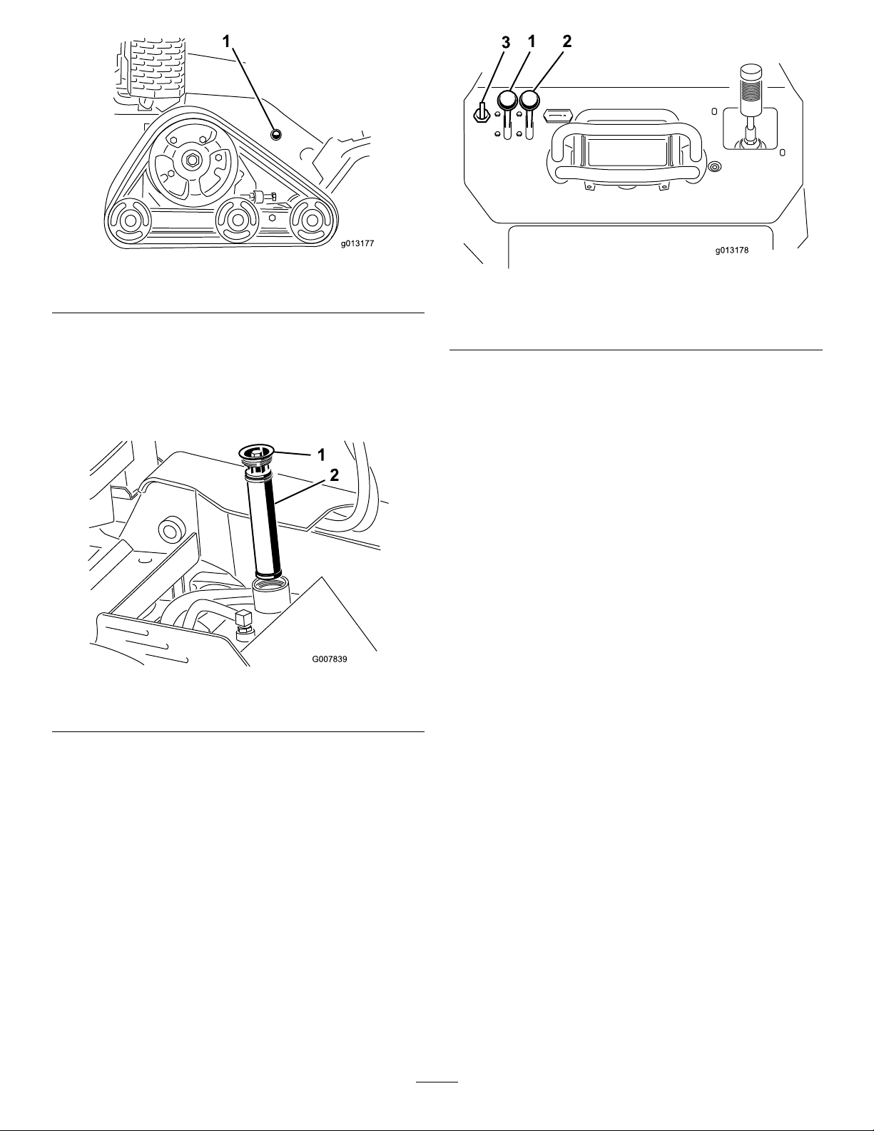
Figure18
g013178
1 2
3
1.Hydraulicuidcheckbubble
4.Removethecoverplate;referto
RemovingtheCoverPlate(page22).
5.Cleantheareaaroundthellerneckofthehydraulic
tankandremovethecapandlterfromtheller
neckusingasocket(
Figure19).
Figure20
1.Throttlelever3.Key
2.Chokelever
2.MovethechokelevertotheOnposition(Figure20).
Note:Awarmorhotenginemaynotrequire
choking.
Figure19
1.Fillerneckcap
2.Hydraulicuidlter
6.Ifthelevelislow,adduiduntilitisvisibleinthe
glassbubble.
7.Installthecapandlteronthellerneckandtorque
boltontopto110to140inch-lb(13to15.5N-m).
8.Installthecoverplate;referto
InstallingtheCoverPlate(page22).
StartingandStoppingthe
3.TurnthekeytotheOnposition(
Figure20).When
theenginestarts,releasethekey .
Important:Donotengagethestarterformore
than10secondsatatime.Iftheenginefails
tostart,allowa30secondcool-downperiod
betweenattempts.Failuretofollowthese
instructionscanburnoutthestartermotor.
4.GraduallymovethechokelevertotheOffposition
Figure20).Iftheenginestallsorhesitates,engage
(
thechokeagainuntiltheenginewarmsup.
5.Movethethrottlelevertothedesiredsetting
Figure20).
(
Important:Iftheengineisrunathighspeeds
whenthehydraulicsystemiscold(i.e.,when
theambientairtemperatureisnearfreezingor
lower),hydraulicsystemdamagecouldoccur.
Whenstartingtheengineincoldconditions,
allowtheenginetoruninthemiddlethrottle
positionfor2to5minutesbeforemovingthe
throttletofast(rabbit).
Note:Iftheoutdoortemperatureisbelowfreezing,
storethemachineinagaragetokeepitwarmerand
aidinstarting.
Engine
StartingtheEngine
1.MovethethrottlelevermidwaybetweenSlowand
Fastpositions(Figure20).
StoppingtheEngine
1.Stopthegrinderandlowerittotheground.
2.MovethethrottlelevertotheSlowposition
(Figure20).
17
Page 18
3.Turnthekeyoff(Figure20).
Note:Iftheenginehasbeenworkinghardor
ishot,letitidleforaminutebeforeturningthe
ignitionkeyoff.Thishelpscooltheenginebefore
itisstopped.Inanemergency,theenginemaybe
stoppedimmediately .
4.Removethekey .
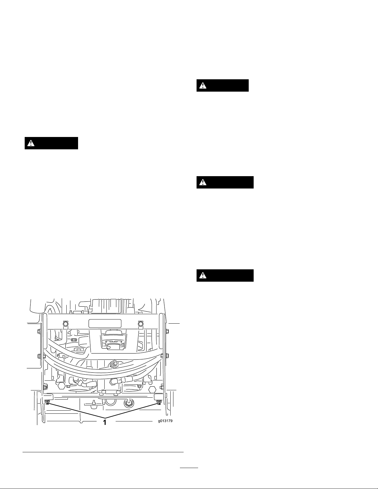
4.Installthebottomshieldandtowthemachineas
required.
5.Whenthemachinehasbeenrepaired,closethetow
valvesbeforeoperatingit.
GrindingaStump
DANGER
StoppingtheMachine
Tostopthemachine,releasethetractioncontrol,move
thethrottlelevertoslow(turtle),lowerthegrinderto
theground,stoptheengine,andremovethekey.
CAUTION
Achildoruntrainedbystandercouldattemptto
operatethemachineandbeinjured.
Removethekeyfromtheswitchwhenleavingthe
machine,evenifjustforafewseconds.
MovingaNon-functioning
Machine
Important:Donottoworpullthemachine
withoutrstopeningthetowvalves,orthe
hydraulicsystemwillbedamaged.
1.Stoptheengine.
2.Removethebottomshield.
3.Usingawrench,turnthetowvalvesonthehydraulic
motorstwicecounter-clockwise(
Figure21).
Thegrinderwillcutandamputatehandsandfeet.
•Stayintheoperator'spositionwhilethegrinder
isrunningandkeepawayfromthegrinder.
•Keepallbystandersasafedistancefromthe
grinder.
•Stopthegrinderimmediatelyifanypeopleor
animalsentertheworkarea.
WARNING
Grindingastumpwillthrowwoodchips,soil,and
otherdebrisintotheairwhichcouldinjureyouor
bystanders.
•Alwaysweareyeprotectionwhenusingthe
grinder.
•Keepallbystandersasafedistancefromthe
grinder.
WARNING
Thegrinderisveryloudwhencuttingastumpand
candamageyourears.
1.Towvalves
Alwayswearhearingprotectionwhenusingthe
grinder.
1.Starttheengine,raisethegrinder,setthethrottle
levertotheFastposition,andmovethemachineto
thestumptobeground.
2.Usethegrindercontrolleverandthetraction
controltopositionthegrindertoonesideofthe
frontofthestump,aboutaninchbelowthesurface
(Figure22).
Figure21
18
Page 19
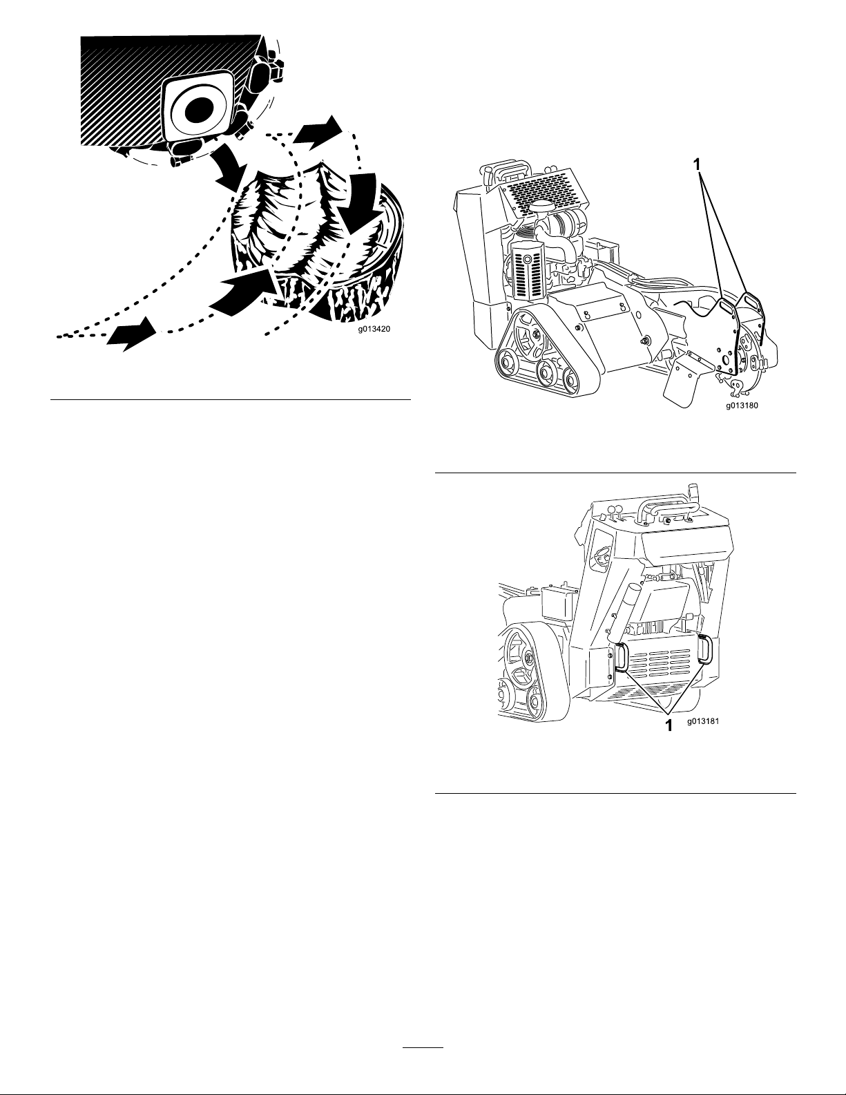
Figure22
2.Lowerthegrinder.
3.Securethemachinetothetrailerwithchainsor
strapsusingthetie-down/liftloopsatthefrontand
rearofthemachine(
toyourlocalordinancesfortrailerandtie-down
requirements.
Figure23andFigure24).Refer
3.Startthegrinderandwaitforittogetuptofull
speed.
4.Usethegrindercontrollevertoswingthegrinder
slowlyacrossthefaceofthestump,cuttingawaya
swathofchips(Figure22).
Important:Donotforcethegrindertomove
toofast.Insteadallowittocutthroughthe
woodwithoutboggingdownorlosingspeed.
5.Movethemachineforwardafewinchesandrepeat
step4(Figure22).
6.Repeatsteps4through5untilyouhavegroundoff
theentirefaceofthestump(Figure22).
7.Backupthemachine,positionthegrindertothe
sideofthefrontofthestump,andlowerittoabout
aninchbelowthesurface.
8.Repeatsteps4through7untilthestumpisground
away.
9.Ifthereareanylargerootstobeground,position
thegrinderovereachrootandusethetraction
controlandgrindercontroltomovethegrinder
alongtheroot,grindingitaway.
Figure23
1.Fronttie-downloop
Figure24
1.Reartie-downloops
LiftingtheMachine
SecuringtheMachinefor
Transport
Whentransportingthemachineonatrailer,alwaysuse
thefollowingprocedure:
Important:Donotoperateordrivethemachine
onroadways.
1.Stoptheengine.
Youcanliftthemachineusingthetie-down/liftloops
asliftpoints(Figure23andFigure24).
OperatingTips
•Cleantheareaoftrash,branchesandrocksbefore
operatingtopreventequipmentdamage.
•Alwaysusefullthrottle(maximumenginespeed)
whengrinding.
19
Page 20
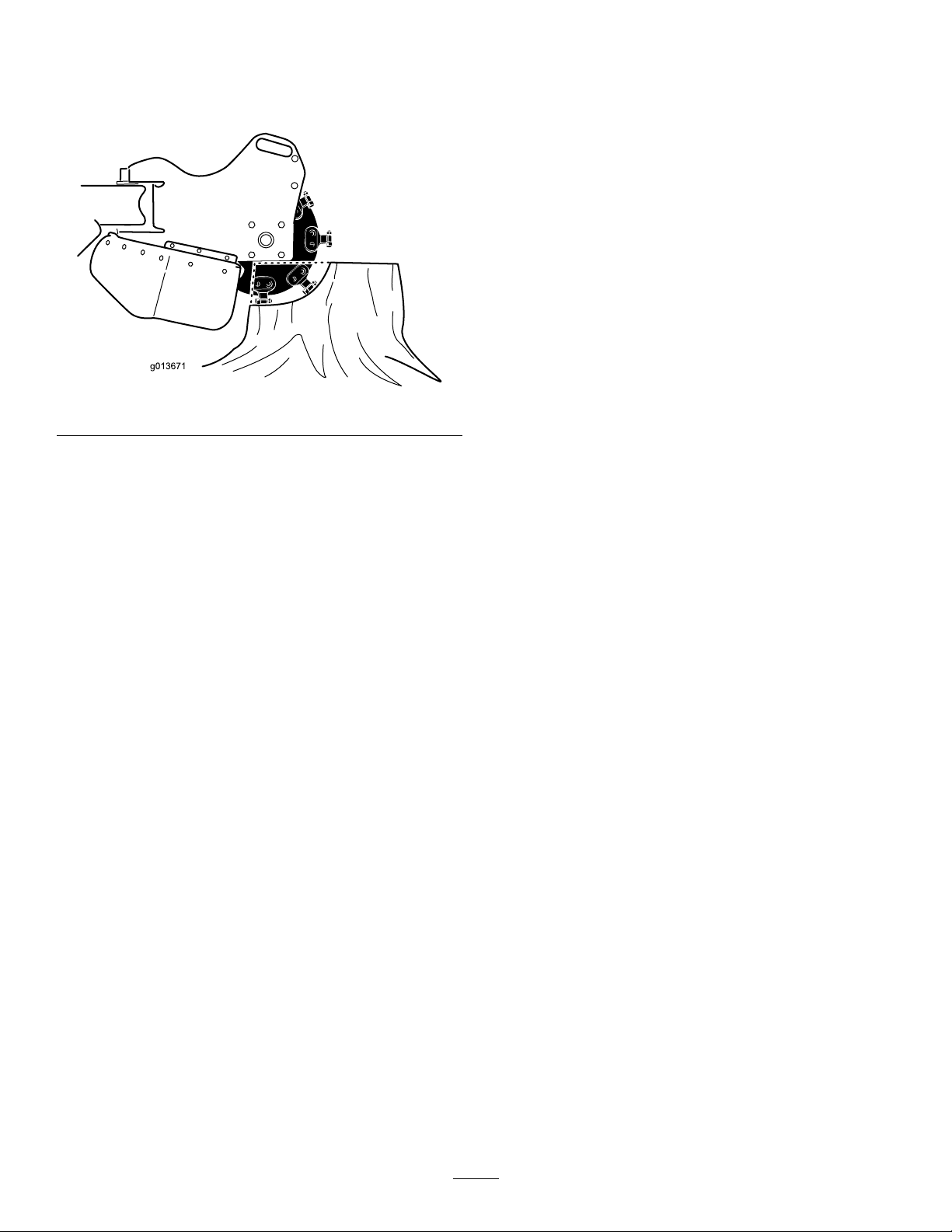
•Cuttheedgesofthestumpformoreefcient
grinding.Onceyourcuttingswathiscloseto1/4of
thewheeldiameter(),liftthegrinder,moveforward
andbegincuttingontheedgeagain.
Figure25
•Listentotheengineandwatchthegrinderwheel
speedtomaintainthespeedofthewheel.Slow
downtheheadsweepbyfeatheringthejoystickas
cuttingbecomesdifcult.
•Asyougrindfromlefttoright,mostofthedebris
willgototheleftofthegrinderwheel.Whenyou
grindfromtherighttoleft,thedebriswillgotothe
right.
•Youmayalsogrindastumpfromthesidetolessen
turfdamage.
20
Page 21

Maintenance
Note:Determinetheleftandrightsidesofthemachinefromthenormaloperatingposition.
RecommendedMaintenanceSchedule(s)
MaintenanceService
Interval
Aftertherst8hours
Aftertherst50hours
Beforeeachuseordaily
Every25hours
Every100hours
Every200hours
Every250hours
MaintenanceProcedure
•Changetheengineoil.
•Checkandadjustthetracktension.
•Checktheengineoillevel.
•Greasethemachine.(Greaseimmediatelyaftereverywashing.)
•Checktheengineoillevel.
•Checktheconditionofandcleanthetracks.
•Checktheconditionoftheteethandrotateorreplaceanythatarewornordamaged.
•Removedebrisfromthemachine.
•Checkforloosefasteners.
•Checkthehydraulicuidlevel.
•Checkthebatteryelectrolytelevel.
•Changetheengineoil.
•Checkthesparkplugs.
•Checkandadjustthetracktension.
•Checkthehydrauliclinesforleaks,loosettings,kinkedlines,loosemounting
supports,wear,weather,andchemicaldeteriorationandrepairifnecessary.
•Changetheoillter.
•Replacethefuellter.
•Replacethehydrauliclter .
•Replacetheprimaryairlterandcheckthecondtionofthesafetylter
•Checkandgreasetheroadwheels.
Every400hours
Every1,500hours
Yearlyorbeforestorage
Important:Refertoyour
•Changethehydraulicuid.
•Replaceallmovinghydraulichoses.
•Checkandadjustthetracktension.
•T ouchupchippedpaint
Engine Operator's Man ual
foradditionalmaintenanceprocedures.
CAUTION
Ifyouleavethekeyintheignitionswitch,someonecouldaccidentlystarttheengineandseriouslyinjure
youorotherbystanders.
Removethekeyfromtheignitionanddisconnectthewirefromthesparkplugbeforeyoudoany
maintenance.Setthewireasidesothatitdoesnotaccidentallycontactthesparkplug.
Premaintenance
Procedures
Beforeopeninganyofthecovers,stoptheengine,
removethekey,andallowtheenginetocool.
Important:Thefastenersonthecoversofthis
machinearedesignedtoremainonthecoverafter
removal.Loosenallofthefastenersoneachcovera
fewturnssothatthecoverisloosebutstillattached,
thengobackandloosenthemuntilthecover
comesfree.Thiswillpreventyoufromaccidentally
strippingtheboltsfreeoftheretainers.
21
Page 22
RemovingtheCoverPlate
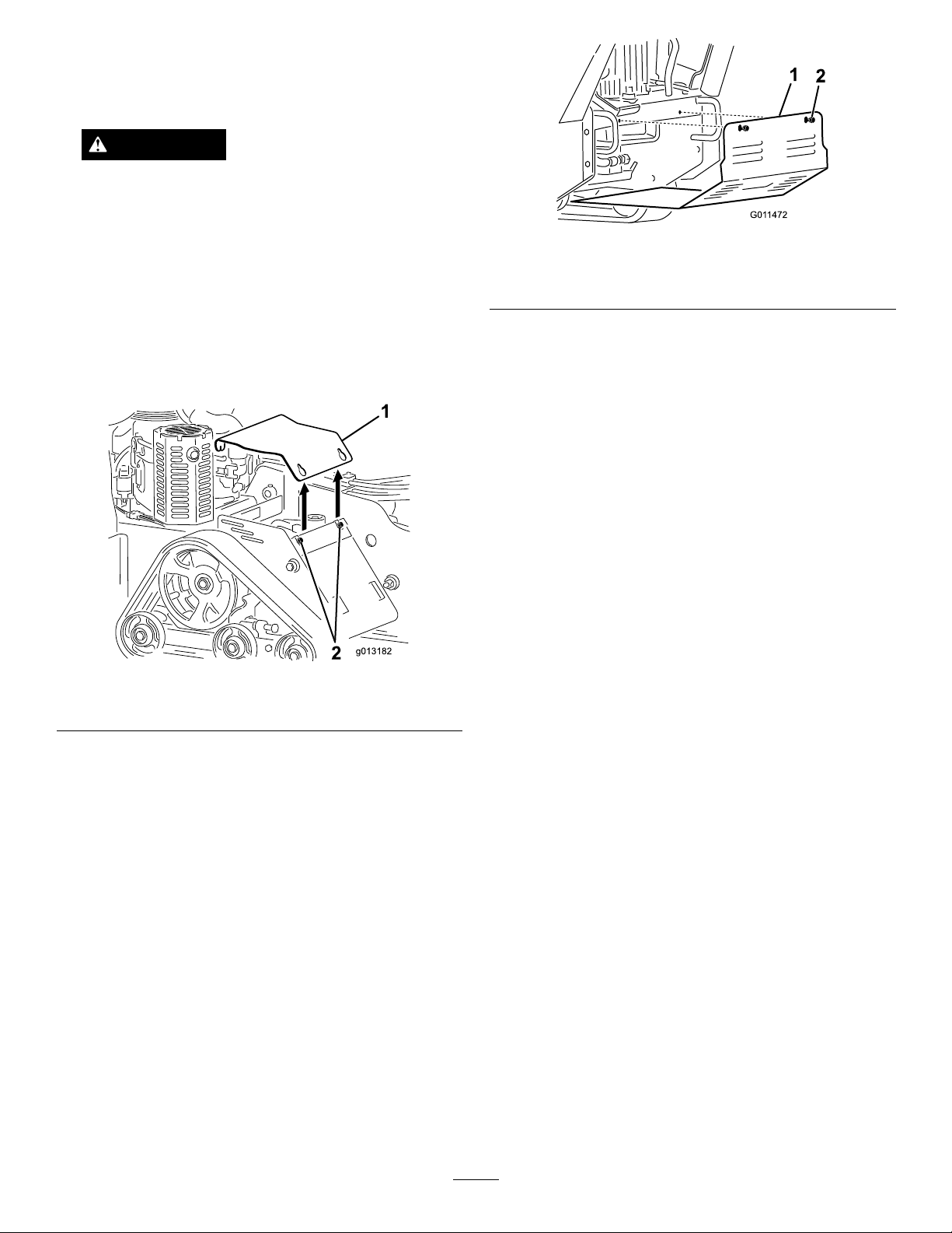
1.Lowerthegrinder,stoptheengine,andremovethe
key.
WARNING
Thereisabeltunderthecoverthatismoving
whenthemachineisrunningandcancatch
ngers,hands,loosehair,andclothing,causing
seriousinjury,amputation,ordeath.
Figure27
Alwaysstoptheengineandwaitforallmoving
partstostopbeforeremovingthecover.
2.Loosentheboltattherearofthecoverplate.
3.Loosenthethreeboltssecuringthecoverplatetothe
framesequentiallyuntilthecoverisfree(
Figure26
1.Coverplate
2.Bolts
Figure26).
1.Bottomshield3.Tabs
2.Bolts
3.Pulltheshieldbackandoutofthemachine.
InstallingtheBottomShield
1.Lowerthegrinder,stoptheengine,andremovethe
key.
2.Slidethebottomshieldintothemachinesothatit
restsonall4tabs(
Note:Youmayneedtoliftuponthebottomshield
toensurethatitrestsonthefronttabs.
3.Securetheshieldwiththeboltsyouloosened
previously.
Figure27).
4.Pullupontherearofthecoverplateuntilitclears
theengineandthenpullitoffofthemachine.
InstallingtheCoverPlate
1.Lowerthegrinder,stoptheengine,andremovethe
key.
2.Slidethecoverplateintoplaceandsecureitwiththe
threeboltsyouloosenedpreviously(
Figure26).
RemovingtheBottomShield
1.Lowerthegrinder,stoptheengine,andremovethe
key.
2.Loosenthetwoboltssecuringthebottomshield
sequentiallyuntiltheshieldisfree(Figure27).
22
Page 23
Lubrication
G011475
1
2
3
4
5
EngineMaintenance
GreasingtheMachine
ServiceInterval:Beforeeachuseordaily(Grease
immediatelyaftereverywashing.)
GreaseType:General-purposegrease.
1.Lowerthegrinderandstoptheengine.Removethe
key.
2.Cleanthegreasettingswitharag.
3.Connectagreaseguntoeachtting(
Figure29).
4.Pumpgreaseintothettingsuntilgreasebeginsto
oozeoutofthebearings(approximately3pumps).
5.Wipeupanyexcessgrease.
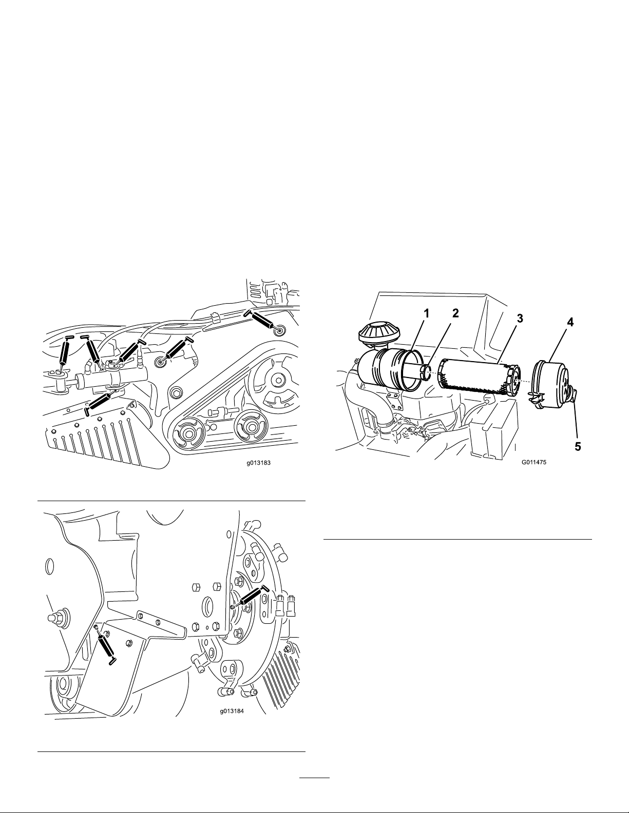
Figure28and
ServicingtheAirCleaner
ServiceInterval:Every250hours
CleaningtheAirCleanerBodyand
Cover
1.Stoptheengineandremovethekey.
2.Checktheaircleanerbodyfordamagewhichcould
causeanairleak.Checkthewholeintakesystem
forleaks,damage,orloosehoseclamps.Replaceor
repairanddamagedcomponents.
3.Releasethelatchesontheaircleanerandpulltheair
cleanercoveroffoftheaircleanerbody(
Important:Donotremovetheairltersyet.
Figure30).
Figure28
1.Airlterbody
2.Safetylter
3.Primarylter
4.Squeezethedustcapsidestoopenitandknockthe
dustout.
5.Cleantheinsideoftheaircleanercoverwith
compressedair.
Figure30
4.Aircleanercover
5.Dustcap
ReplacingtheFilters
Figure29
1.Gentlyslidetheprimarylteroutoftheaircleaner
body(Figure30).Avoidknockingthelterintothe
sideofthebody.
Important:Donotattempttocleantheprimary
lter.
2.Checktheconditionofthesafetylterwithout
removingit.Ifitisdirtyordamaged,replaceit.
23
Page 24
Important:Neverattempttocleanthesafety
lter.
3.Inspectthenewlter(s)fordamagebylookinginto
thelterwhileshiningabrightlightontheoutside
ofthelter.Holesinthelterwillappearasbright
spots.Inspecttheelementfortears,anoilylm,or
damagetotherubberseal.Ifthelterisdamaged
donotuseit.
4.Ifyouarereplacingthesafetylter,carefullyslide
thenewlterintothelterbody(
Figure30).
Important:Topreventenginedamage,always
operatetheenginewithbothairltersandcover
installed.
5.Carefullyslidetheprimarylteroverthesafetylter
Figure30).Ensurethatitisfullyseatedbypushing
(
ontheouterrimofthelterwhileinstallingit.
Important:Donotpressonthesoftinsidearea
ofthelter.
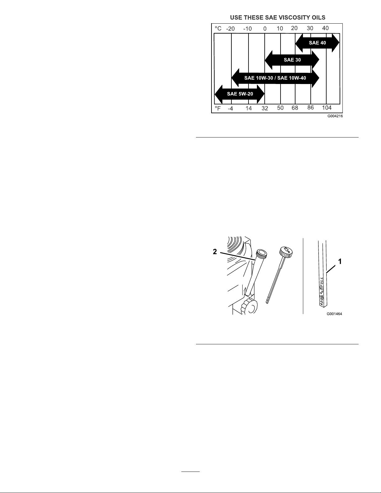
Figure31
CheckingtheEngineOilLevel
1.Parkthemachineonalevelsurface.
2.Lowerthegrinder.
6.Installtheaircleanercoverwiththedustcaporiented
asshownin
Figure30andsecurethelatches.
ServicingtheEngineOil
ServiceInterval:Aftertherst8hours—Changethe
engineoil.
Beforeeachuseordaily—Checkthe
engineoillevel.
Every100hours—Changetheengine
oil.
Every200hours—Changetheoil
lter.
Note:Changetheoilmorefrequentlywhenthe
operatingconditionsareextremelydustyorsandy.
OilType:Detergentoil(APIserviceSF,SG,SH,orSJ)
CrankcaseCapacity:58ounces(1.7liter)withthelter
removed;51ounces(1.5liter)withoutthelterremoved
Viscosity:Refertothetable(
Figure31).
3.Stoptheengine,removethekey,andwaitforall
movingpartstostopbeforeleavingtheoperating
position.
4.Cleanaroundtheoildipstick(
Figure32)sothatdirt
cannotfallintothellerholeanddamagetheengine.
Figure32
1.Oildipstick
2.Fillertube
5.Unscrewtheoildipstickandwipetheendclean
(Figure32).
6.Slidetheoildipstickfullyintothellertube,butdo
notthreadontotube(Figure32).
7.Pullthedipstickoutandlookattheend.Iftheoil
levelislow ,slowlypouronlyenoughoilintotheller
tubetoraisetheleveltotheFullmark.
Important:Donotoverllthecrankcasewith
oilandruntheengine;enginedamagecan
result.
24
Page 25
ChangingtheOil
1.Starttheengineandletitrunveminutes.This
warmstheoilsoitdrainsbetter.
2.Parkthemachinesothatthedrainsideisslightly
lowerthantheoppositesidetoensurethattheoil
drainscompletely .
3.Lowerthegrinder.
4.Stoptheengine,removethekey,andwaitforall
movingpartstostopbeforeleavingtheoperating
position.
Figure34
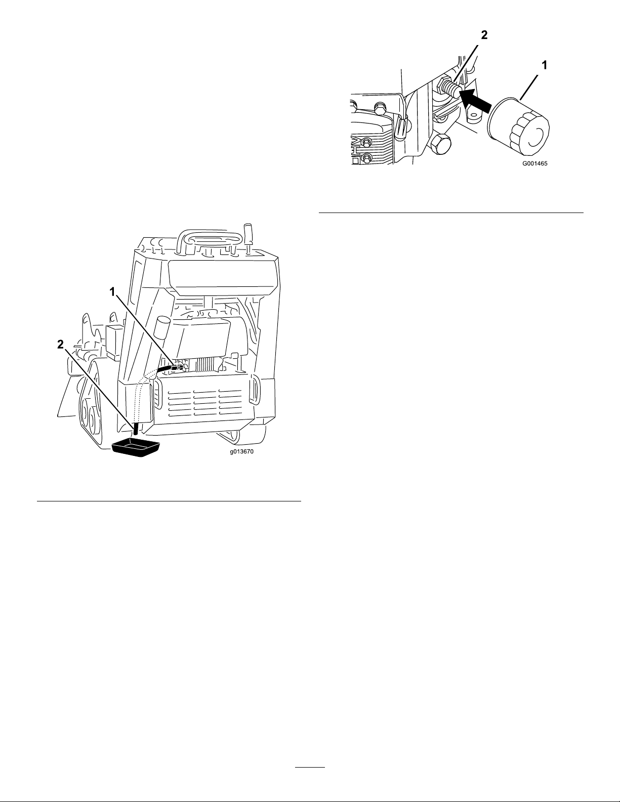
5.Placeapanbelowthedrainhose.Rotatetheoildrain
valvetoallowoiltodrain(
Figure33
1.Oildrainvalve2.Oildrainhose
Figure33).
1.Oillter
2.Adapter
3.Applyathincoatofnewoiltotherubbergasketon
thereplacementlter(Figure34).
4.Installthereplacementoilltertothelteradapter,
turntheoillterclockwiseuntiltherubbergasket
contactsthelteradapter,thentightenthelteran
additional3/4turn(
Figure34).
5.Fillthecrankcasewiththepropertypeofnewoil;
refertoServicingtheEngineOil.
6.Runtheengineforabout3minutes,stoptheengine,
andcheckforoilleaksaroundtheoillteranddrain
valve.
7.Checktheengineoillevelandaddoilifneeded.
8.Wipeupanyspilledoil.
ServicingtheSparkPlug
ServiceInterval:Every100hours—Checkthespark
plugs.
6.Whenoilhasdrainedcompletely,closethedrain
valve.
7.Disposeoftheusedoilatarecyclingcenter
8.Slowlypourapproximately80%ofthespeciedoil
intothellertube(
Figure32).
9.Checktheoillevel;referto
CheckingtheEngineOilLevel(page16).
10.SlowlyaddtheadditionaloiltobringittotheFull
mark.
ChangingtheOilFilter
1.Draintheoilfromtheengine;referto
ChangingtheOil(page25).
2.Removetheoldlter(
Figure34).
Ensurethattheairgapbetweenthecenterandside
electrodesiscorrectbeforeinstallingthesparkplug.
Useasparkplugwrenchforremovingandinstallingthe
sparkplugandagappingtool/feelergaugetocheckand
adjusttheairgap.Installanewsparkplugifnecessary.
Type:Model23210—NGKBPR4Esorequivalent;Air
Gap:0.030inch(0.75mm)
RemovingtheSparkPlug
1.Lowerthegrinder.
2.Stoptheengine,removethekey,andwaitforall
movingpartstostopbeforeleavingtheoperating
position.
3.Disconnectthewirefromthesparkplug(Figure35).
25
Page 26
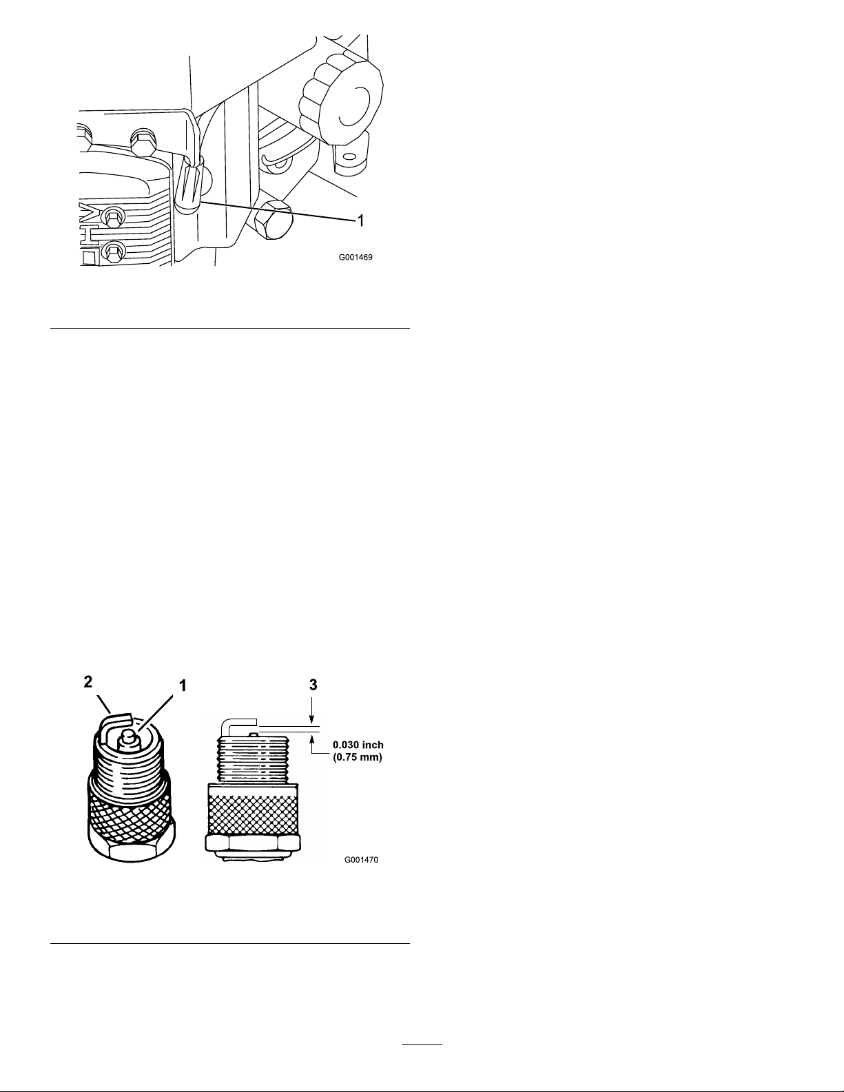
1
Figure35
1.Spark-plugwire/sparkplug
4.Cleanaroundthesparkplugtopreventdirtfrom
fallingintotheengineandpotentiallycausing
damage.
Note:Theheatshieldmayinterfereontheright
side;removeitifnecessaryandreplaceitwhen
nished.
Important:Alwaysreplacethesparkplugwhen
ithaswornelectrodes,anoilylmonit,orhas
cracksintheporcelain.
3.Checkthegapbetweenthecenterandsideelectrodes
Figure36).Bendthesideelectrode(Figure36)if
(
thegapisnotcorrect.
InstallingtheSparkPlug
1.Installthesparkplugandthemetalwasher.Ensure
thattheairgapissetcorrectly.
2.Tightenthesparkplugto16ft-lb(22N-m).
3.Connectthewiretothesparkplug(
Figure36).
5.Removethesparkplugandthemetalwasher.
CheckingtheSparkPlug
1.Lookatthecenterofthesparkplug(Figure36).
Ifyouseelightbrownorgrayontheinsulator,the
engineisoperatingproperly .Ablackcoatingonthe
insulatorusuallymeansthattheaircleanerisdirty.
2.Ifneeded,cleanthesparkplugwithawirebrushto
removecarbondeposits.
Figure36
1.Centerelectrodeinsulator3.Airgap(nottoscale)
2.Sideelectrode
26
Page 27
FuelSystem
Maintenance
DrainingtheFuelTank
DANGER
Incertainconditions,gasolineisextremely
ammableandhighlyexplosive.Areorexplosion
fromgasolinecanburnyouandothersandcan
damageproperty.
•Draingasolinefromthefueltankwhenthe
engineiscold.Dothisoutdoorsinanopenarea.
Wipeupanygasolinethatspills.
7.Installthefuellineontothefuelshut-offvalve.Slide
thehoseclampclosetothevalvetosecurethefuel
line.
8.Wipeupanyspilledfuel.
ReplacingtheFuelFilter
ServiceInterval:Every200hours
Neverinstalladirtylterifitisremovedfromthefuel
line.
Note:Notehowthefuellterisinstalledinorderto
installthenewltercorrectly.
Note:Wipeupanyspilledfuel.
•Neversmokewhendraininggasoline,andstay
awayfromanopenameorwhereasparkmay
ignitethegasolinefumes.
1.Parkthemachineonalevelsurface,toensurethat
thefueltankdrainscompletely.
2.Lowerthegrinder.
3.Stoptheengine,removethekey,andwaitforall
movingpartstostopbeforeleavingtheoperating
position.
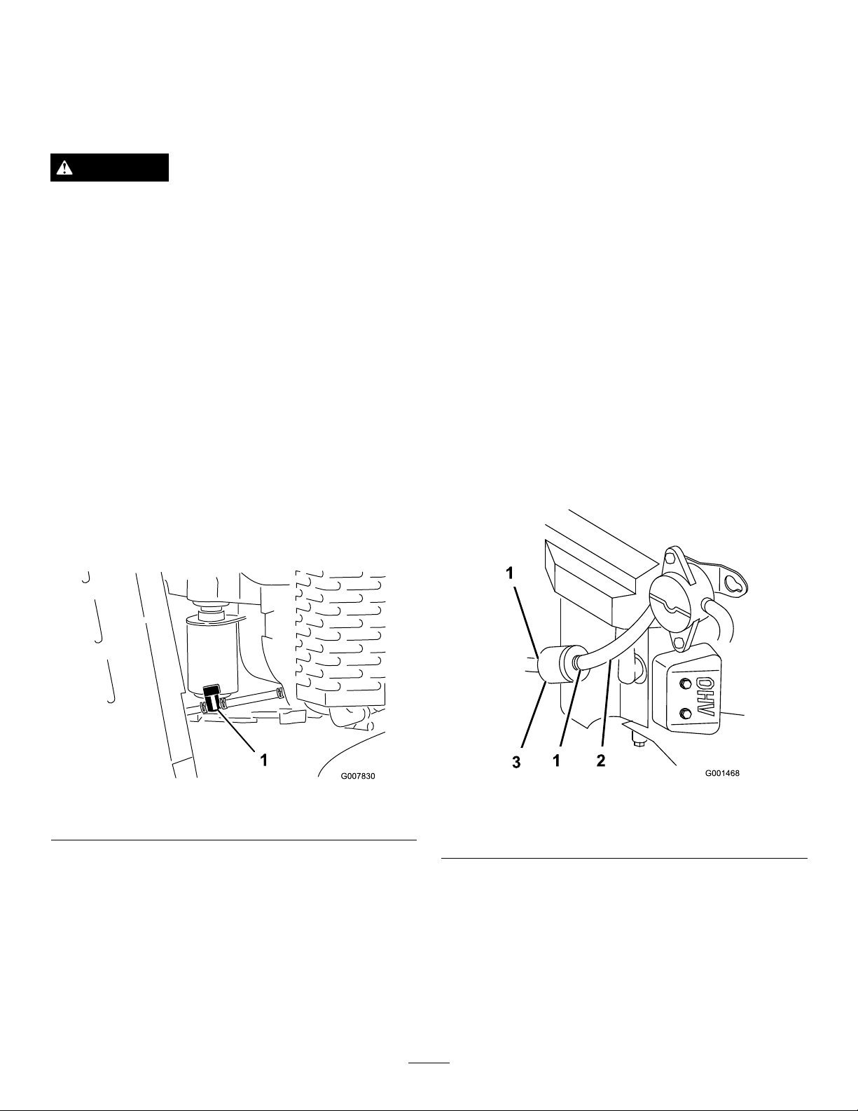
4.Turnthefuelshut-offvalvetotheclosedposition
(Figure37).
1.Lowerthegrinder.
2.Stoptheengine,removethekey,andwaitforall
movingpartstostopbeforeleavingtheoperating
position.
3.Turnthefuelshut-offvalvetotheclosedposition
Figure37).
(
4.Squeezetheendsofthehoseclampstogetherand
slidethemawayfromthelter(Figure38).
Figure37
1.Fuelshut-offvalve
5.Squeezetheendsofthehoseclampontheengine
sideoftheshut-offvalvetogetherandslideitupthe
fuellineawayfromvalve(
6.Pullthefuellineoffthevalve(
fuelshut-offvalveandallowthegasolinetodrain
intoagascanordrainpan.
Note:Nowisthebesttimetoinstallanewfuellter
becausethefueltankisempty.RefertoReplacing
theFuelFilter.
Figure37).
Figure37).Openthe
Figure38
1.Hoseclamp3.Filter
2.Fuelline
5.Removethelterfromthefuellines.
6.Installanewlterandmovethehoseclampsclose
tothelter.
7.Turnthefuelshut-offvalvetotheopenposition
(Figure37).
8.Checkforfuelleaksandrepairifneeded.
9.Wipeupanyspilledfuel.
27
Page 28
ElectricalSystem
Maintenance
ServicingtheBattery
ServiceInterval:Every25hours—Checkthebattery
electrolytelevel.
Alwayskeepthebatterycleanandfullycharged.Use
apapertoweltocleanthebatterycase.Ifthebattery
terminalsarecorroded,cleanthemwithasolutionof
fourpartswaterandonepartbakingsoda.Applyalight
coatingofgreasetothebatteryterminalstoprevent
corrosion.
Voltage:12Vwith280coldcrankingAmps@0degrees
F(-18degreesC).
WARNING
Incorrectbatterycableroutingcoulddamagethe
machineandcablescausingsparks.Sparkscan
causethebatterygassestoexplode,resultingin
personalinjury.
•AlwaysDisconnectthenegative(black)battery
cablebeforedisconnectingthepositive(red)
cable.
•AlwaysReconnectthepositive(red)battery
cablebeforereconnectingthenegative(black)
cable.
1.Lowerthegrinder.
2.Stoptheengine,removethekey,andwaitforall
movingpartstostopbeforeleavingtheoperating
position.
WARNING
CALIFORNIA
Proposition65Warning
Batteryposts,terminals,andrelated
accessoriescontainleadandleadcompounds,
chemicalsknowntotheStateofCalifornia
tocausecancerandreproductiveharm.
Washhandsafterhandling.
DANGER
Batteryelectrolytecontainssulfuricacidwhichisa
deadlypoisonandcausessevereburns.
Donotdrinkelectrolyteandavoidcontactwith
skin,eyesorclothing.Wearsafetyglassestoshield
youreyesandrubberglovestoprotectyourhands.
RemovingtheBattery
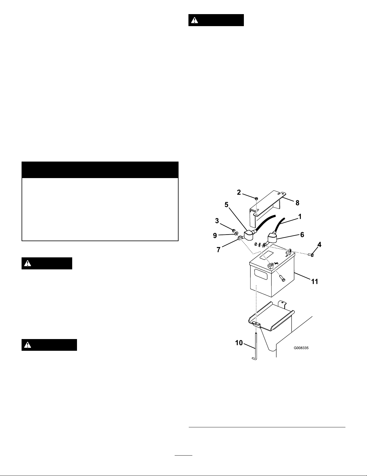
3.Lifttheblackrubbercoveronthenegativecable.
Disconnectthenegativebatterycablefromthe
negative(-)batteryterminal(
Figure39).
WARNING
Batteryterminalsormetaltoolscouldshortagainst
metalmachinecomponentscausingsparks.Sparks
cancausethebatterygassestoexplode,resulting
inpersonalinjury.
•Whenremovingorinstallingthebattery,donot
allowthebatteryterminalstotouchanymetal
partsofthemachine.
•Donotallowmetaltoolstoshortbetween
thebatteryterminalsandmetalpartsofthe
machine.
Figure39
1.Negativecable7.Positivecable
2.Nut(1/4inch)
3.Nut(5/16inch)
4.Bolt10.J-bolt
5.Rubbercover(red)
6.Rubbercover(black)
28
8.Batteryholddownplate
9.Washer
11.Battery
Page 29
4.Slidetheredterminalbootoffthepositive(red)
batteryterminal.Thenremovethepositive(red)
batterycable(Figure39).
5.Removetheholddownplate,j-bolts,andlocknuts
securingthebattery(
battery.
Figure39)andremovethe
AddingWatertotheBattery
Thebesttimetoadddistilledwatertothebatteryisjust
beforeyouoperatethemachine.Thisletsthewatermix
thoroughlywiththeelectrolytesolution.
1.Removethebatteryfromthemachine;referto
RemovingtheBattery.
InstallingtheBattery
1.Placethebatteryontothemachine(Figure39).
2.Securethebatterywiththeholddownplate,j-bolts,
andlocknuts.
3.First,installthepositive(red)batterycableto
positive(+)batteryterminalwithanut,washerand
Figure39).Slidetherubbercoveroverthepost.
bolt(
4.Theninstallthenegativebatterycableandground
wiretothenegative(-)batteryterminalwithanut,
washerandbolt(
overthepost.
Figure39).Slidetherubbercover
CheckingtheBatteryElectrolyteLevel
DANGER
Batteryelectrolytecontainssulfuricacidwhichisa
deadlypoisonandcausessevereburns.
•Donotdrinkelectrolyteandavoidcontactwith
skin,eyesorclothing.Wearsafetyglassesto
shieldyoureyesandrubberglovestoprotect
yourhands.
Important:Neverllthebatterywithdistilled
waterwhilethebatteryisinstalledinthe
machine.Electrolytecouldbespilledonother
partsandcausecorrosion.
2.Cleanthetopofthebatterywithapapertowel.
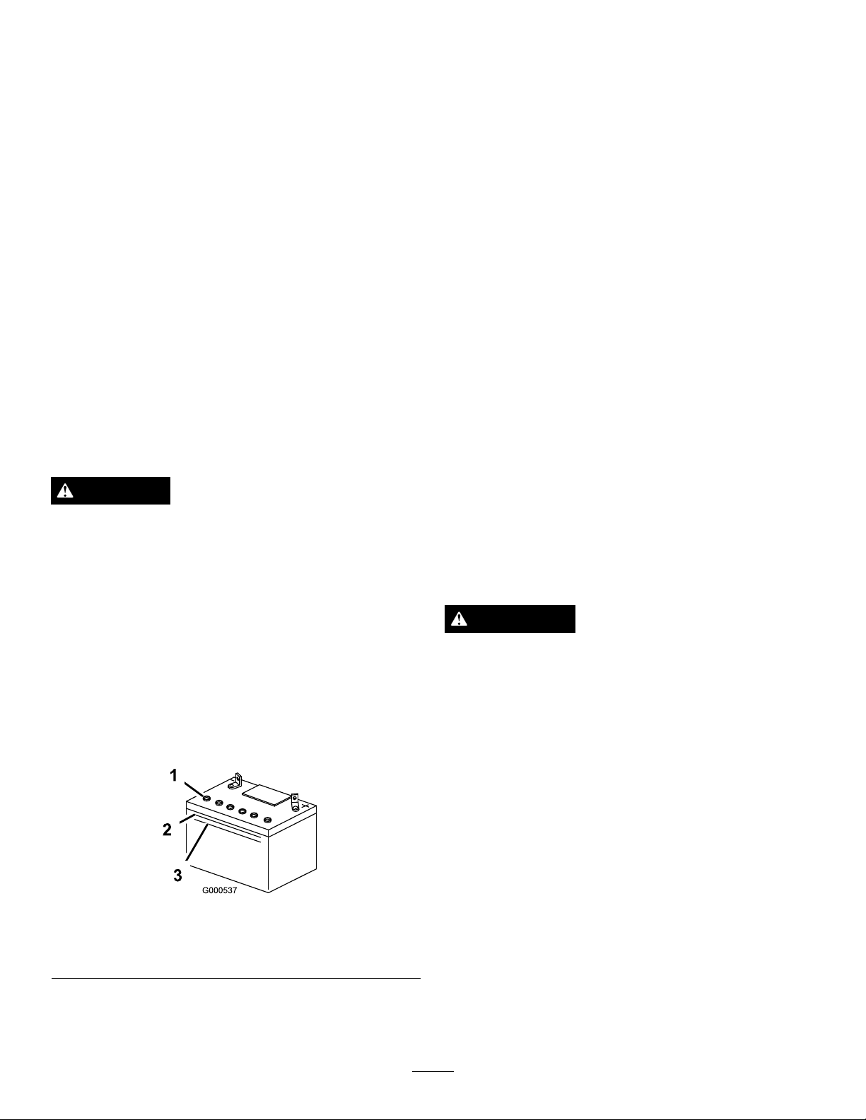
3.Removetheventcapsfromthebattery(
4.Slowlypourdistilledwaterintoeachbatterycell
untiltheelectrolytelevelisuptotheUpperline
Figure40)onthebatterycase.
(
Important:Donotoverllthebatterybecause
electrolyte(sulfuricacid)cancausesevere
corrosionanddamagetothechassis.
5.Waitvetotenminutesafterllingthebatterycells.
Adddistilledwater,ifnecessary,untiltheelectrolyte
levelisuptotheUpperline(
batterycase.
6.Installthebatteryventcaps.
Figure40)onthe
Figure40).
ChargingtheBattery
WARNING
•Fillthebatterywherecleanwaterisalways
availableforushingtheskin.
1.Lookatthesideofthebattery.Theelectrolytemust
beuptotheupperline(Figure40).Donotallowthe
electrolytetofallbelowtheLowerline(Figure40).
Figure40
1.Ventcaps3.Lowerline
2.Upperline
2.Iftheelectrolyteislow,addtherequiredamountof
distilledwater;refertoAddingW atertotheBattery.
Chargingthebatteryproducesgassesthatcan
explode.
Neversmokenearthebatteryandkeepsparksand
amesawayfrombattery.
Important:Alwayskeepthebatteryfullycharged
(1.265specicgravity).Thisisespeciallyimportant
topreventbatterydamagewhenthetemperatureis
below32°F(0°C).
1.Removethebatteryfromthechassis;referto
RemovingtheBattery.
2.Checktheelectrolytelevel;refertoCheckingthe
ElectrolyteLevel.
3.Makesurethellercapsareinstalledinbattery.
Connecta3to4ampbatterychargertothebattery
posts.Chargethebatteryatarateof3to4amperes
for4to8hours(12volts).Donotoverchargethe
battery.
29
Page 30

4.Whenthebatteryisfullycharged,unplugthecharger
fromtheelectricaloutlet,thendisconnectthe
chargerleadsfromthebatteryposts(Figure41).
5.Installthebatteryontothemachineandconnectthe
batterycables,refertoInstallingtheBattery.
Note:Donotrunthemachinewiththebattery
disconnected,electricaldamagemayoccur.
Figure41
1.PositiveBatteryPost
2.NegativeBatteryPost
3.Red(+)ChargerLead
4.Black(-)ChargerLead
ReplacingtheFuses
Thereare4fusesintheelectricalsystem.Theyareunder
thecontrolpanelontheleftside(Figure42).
DriveSystem
Maintenance
ServicingtheTracks
CleaningtheTracks
ServiceInterval:Beforeeachuseordaily
Checkthetracksforexcessivewearandcleanthem
periodically.Ifthetracksareworn,replacethem.
1.Lowerthegrinder.
2.Stoptheengine,removethekey,andwaitforall
movingpartstostopbeforeleavingtheoperating
position.
3.Usingawaterhoseorpressurewasher,removedirt
fromeachtracksystem.
Important:Ensurethatyouusehigh-pressure
watertowashonlythetrackarea.Donotuse
ahigh-pressurewashertocleantherestofthe
machine.High-pressurewashingcandamagethe
electricalsystemandhydraulicvalvesordeplete
grease.
Important:Ensurethatyoufullycleantheroad
wheelsandthedrivesprocket(
Figure43).
StartCircuit
ChargeCircuit
CoolerfanCircuit
Headlight(optional)
1.Fuseblock
Figure42
30amp
25amp
15amp
15amp
Figure43
1.Roadwheels3.Track
2.Drivesprocket
CheckingandAdjustingtheTrack
Tension
ServiceInterval:Aftertherst50hours
Every100hours
Tocheckthetensionofeachtrack,place45lb(20.4kg)
onthetrackmidwaybetweenthefrontroadwheeland
30
Page 31
thedrivesprocket.Thetrackshouldexnomorethan
1/4to3/8inch(0.6to1cm).Ifitdoes,adjustthetrack
tensionusingthefollowingprocedure:
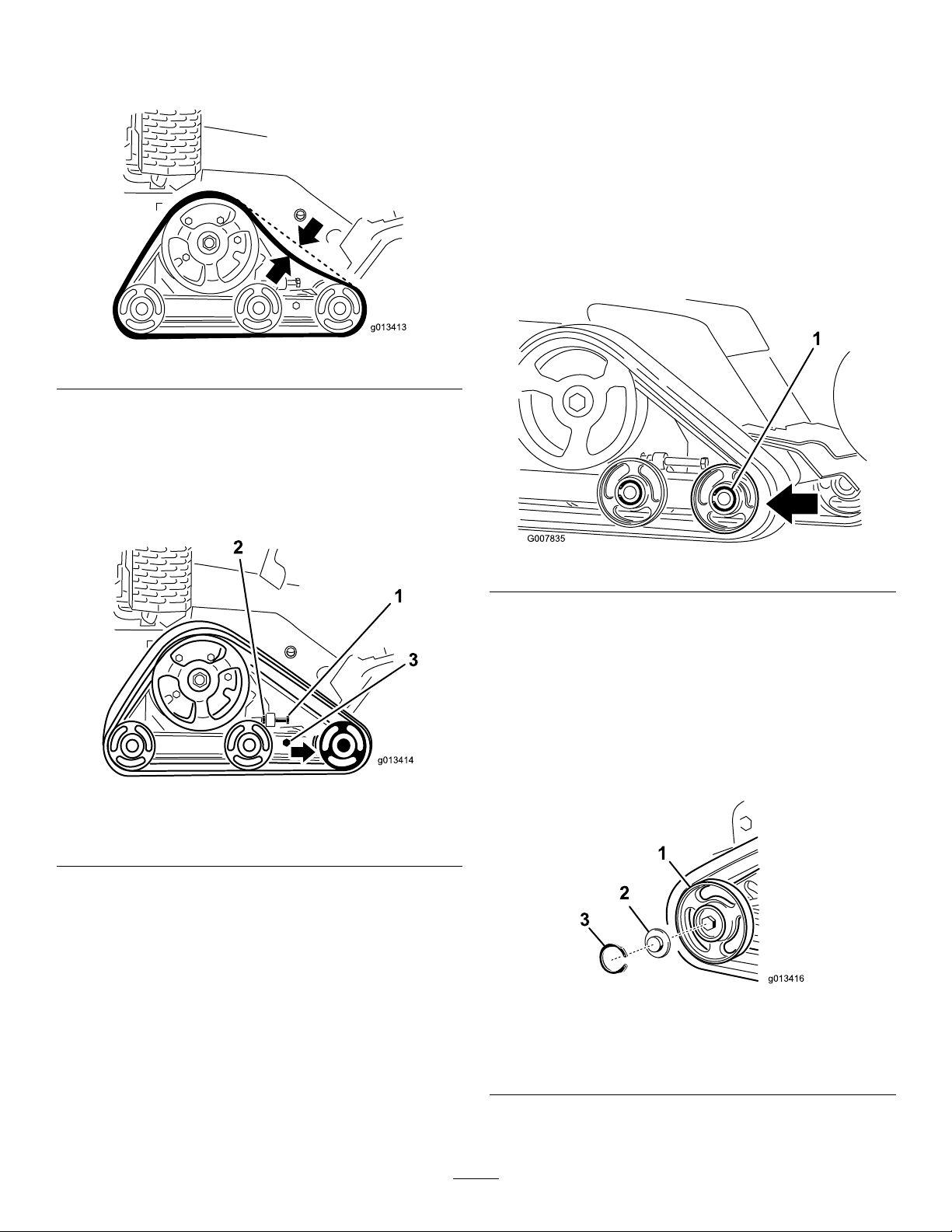
Figure44
1.Stopthemachineinonalevelsurface.
2.Stoptheengine,lowerthegrinder,removethekey ,
andwaitforallmovingpartstostopbeforeleaving
theoperatingposition.
3.Loosenthejamnutonthetracktensioningboltand
theclampboltsonthetensionarm(
Figure45).
1.Lowerthegrinder.
2.Stoptheengine,removethekey,andwaitforall
movingpartstostopbeforeleavingtheoperating
position.
3.Lift/supportthesideoftheunittobeworkedon
sothatthetrackis3to4inches(7.6to10cm)off
oftheground.
4.Backoutthetensioningboltandjamnut(Figure45).
5.Loosentheclampbolts(
Figure45).
6.Pushthefrontroadwheelrearwardasfarasitwill
go(Figure46).
Figure45
1.Tensioningbolt
2.Jamnut
3.Clampbolts
4.Torquethetensioningboltto24to30ft-lb(32.5to
40N-m)totightenthetrack(Figure45).
5.Ensurethatthetrackdeectslessthan1/4to3/8
inch(0.6to1cm)when45lb(20.6kg)offorceis
appliedtothetrackspan.Adjustthetorqueonthe
tensioningboltasneeded.
6.Tightenthejamnut.
7.Tightentheclampboltsandtorqueto75ft-lb(102
N-m).
Figure46
7.Beginremovingthetrackatthetopofthefrontroad
wheel,peelingitoffofthewheelwhilerotatingthe
trackforwards.
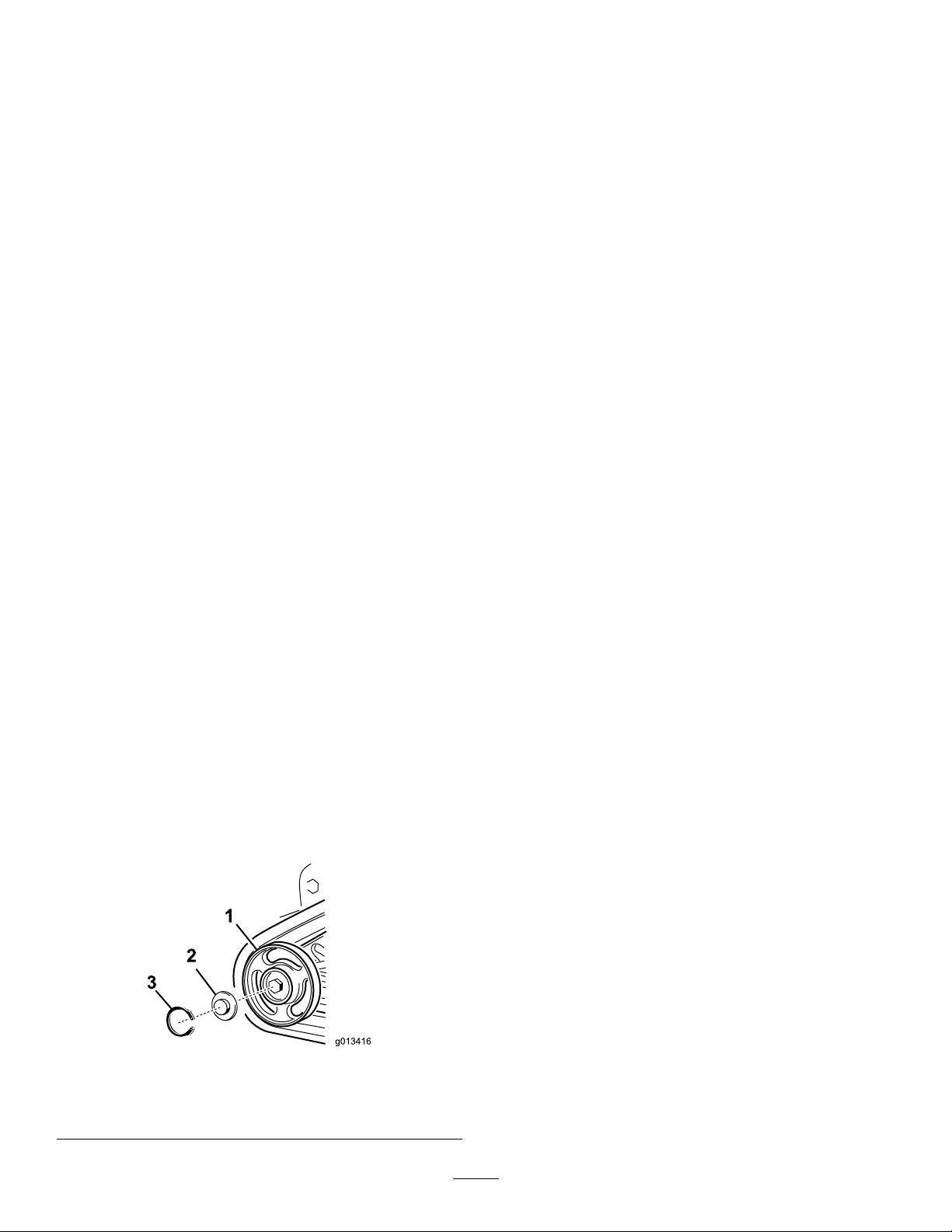
Note:Youmayneedtoremovethefront,outside
roadwheel.Toremovethiswheel,removethesnap
ringandcapfromthecenteroftheroadwheel
Figure47).Nextremovetheboltandgasketfrom
(
thecenterofthewheelandpullthewheeloffofthe
machine.
Figure47
1.Snapring4.Gasket
2.Cap
3.Bolt
5.Wheelwithbearings
ReplacingtheTracks
Whenthetracksarebadlyworn,replacethem.
8.Whenthetrackisoffoftheroadwheel,removeit
fromthemachine(Figure46).
31
Page 32
9.Beginningatthedrivesprocket,coilthenewtrack
aroundthesprocket,ensuringthatthelugson
thetracktbetweenthespacersonthesprocket
Figure46).
(
3.Checkthegreaseunderthecapandaroundthe
gasket(Figure48).Ifitisdirty,gritty,ordepleted,
cleanoutallofthegrease,replacethegasket,and
addnewgrease.
10.Pushthetrackunderandbetweentherearandcenter
roadwheels(Figure46).
11.Startingatthebottomofthefrontroadwheel,install
thetrackaroundthewheelbyrotatingthetrack
rearwardwhilepushingthelugsintothewheel.
12.Ifyouremovedthefront,outsideroadwheel,install
itatthistimeusingtheboltandgasketremoved
previously.Torquetheboltto75ft-lb(102N-m)
andthenclean,grease,andinstallthecapandsnap
ringasinstructionintheCheckingandGreasingthe
RoadWheelssection.
13.Installthetensioningboltandjamnut.
14.Torquethetensioningboltto24to30ft-lb(32.5to
40N-m)totightenthetrack.
15.Ensurethatthetrackdeectslessthan1/4to3/8
inch(0.6to1cm)when45lb(20.6kg)offorceis
appliedtothetrackspan.Adjustthetorqueonthe
tensioningboltasneeded.
16.Tightenthejamnut.
17.Tightentheclampboltsandtorqueto75ft-lb(102
N-m).
4.Ensurethattheroadwheelturnssmoothlyonthe
bearing.Ifitisfrozen,contactyourAuthorized
ServiceDealertoreplacetheroadwheel.
5.Placethegreasedroadwheelcapoverthebolthead
Figure48).
(
6.Securetheroadwheelcapwiththesnapring
(Figure48).
7.Repeatsteps2through6forall12roadwheels.
8.Installthetracks;referto
ReplacingtheTracks(page31).
18.Lowerthemachinetotheground.
19.Repeatsteps3through18toreplacetheothertrack.
CheckingandGreasingtheRoad
Wheels
ServiceInterval:Every250hours
1.Removethetracks;referto
ReplacingtheTracks(page31).
2.Removethesnapringandcapfromaroadwheel
(Figure48).
Figure48
1.Roadwheel
2.Roadwheelcap
3.Snapring
32
Page 33
BeltMaintenance
ControlsSystem
ReplacingthePumpDriveBelt
Ifthepumpdrivebeltbeginstosquealoriscracked,
worn,orfrayed,replaceit.ContactyouAuthorized
ServiceDealerforareplacementbelt.
1.Raisethegrinder.
2.Stoptheengine,removethekey,andwaitforall
movingpartstostopbeforeleavingtheoperating
position.
3.Raisethebackofthemachineandsupportitonjack
stands.
4.Removethebottomshield;refertoRemovingthe
BottomShield.
5.Loosenthetwopumpbolts(
Figure49).
Maintenance
Thefactoryadjuststhecontrolsbeforeshippingthe
machine.However,aftermanyhoursofuse,youmay
needtoadjustthetractioncontrolalignment,theneutral
positionofthetractioncontrol,andthetrackingofthe
tractioncontrolinthefullforwardposition.
Important:Toadjustthecontrolsproperly,
completeeachprocedureintheorderlisted.
AdjustingtheTractionControl
Alignment
Ifthetractioncontrolbardoesnotrestushand
squarewiththereferencebarwheninthefullbackward
position,immediatelycompletethefollowingprocedure:
1.Parkthemachineonaatsurfaceandlowerthe
grinder.
2.Stoptheengineandremovethekey.
3.Pullstraightbackonthetractioncontrolsothefront
ofthecontrolcontactsthereferencebar(
Figure50).
Figure49
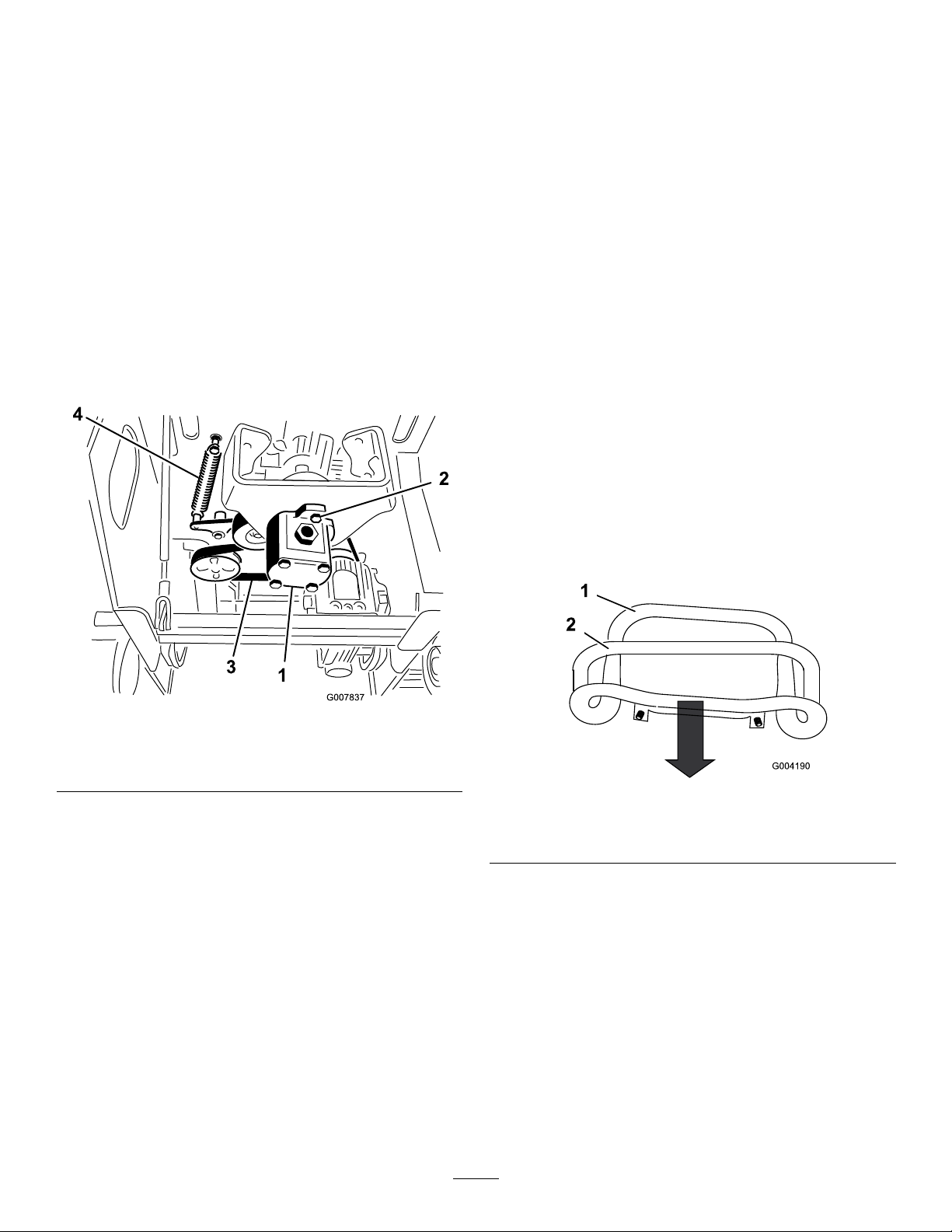
1.Pump3.Belt
2.Pumpbolts4.Idlerpulleyspring
6.Twistthepumpcounterclockwiseandallowitto
dropdownawayfromthepulley(Figure49).Ensure
thatthespidercouplerdropsdownwiththepump.
7.Usingaspringpuller(contactyourAuthorized
ServiceDealer)orstiffmetalhook,pulltheendof
theidlerpulleysprintoffofthespringbolttorelease
tensiononthebelt(Figure49).
8.Removethebelt.
9.Routeanewbeltaroundthepulleys.
10.Installtheidlerpulleyspringonthebolt.
11.Ensurethatthespidercouplerisinplaceonthe
pumpandtheninsertitintothepulley,twistingit
clockwisetoseatitonthepumpbolts.
12.Torquethepumpboltsto50ft-lb(68N-m).
13.Installthebottomshield.
Figure50
1.Frontofthecontrol,outof
alignment
4.Ifthefrontofthetractioncontroldoesnotrest
squareandushwiththereferencebar,loosenthe
angenutandboltinthestemofthetractioncontrol
(Figure51).
2.Referencebar
33
Page 34
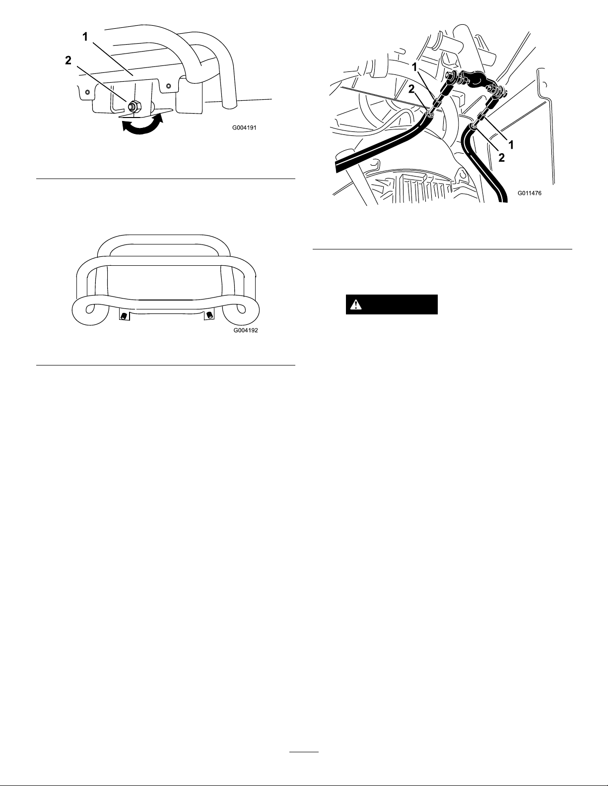
Figure51
G011476
1
1
2
2
1.Tractioncontrol
2.Stem,boltandnut
5.Adjustthetractioncontrolsothatitrestsush
againstthereferencebarwhenitispulledstraight
Figure51andFigure52).
back(
Figure52
6.Tightentheangenutandboltinthetraction
controlstem.
7.Starttheengine.
8.Drivethemachineinreversewiththetraction
controltighttothereferencebar.Ifthemachine
doesnotbackupstraight,completethefollowing
procedure:
Figure53
1.Tractionrod2.Jamnut
E.Startthemachineandsetthethrottletoabout
1/3openposition.
WARNING
Whenthemachineisrunning,youcould
becaughtandinjuredinmovingpartsor
burnedonhotsurfaces.
Stayawayfrompinchpoints,movingparts,
andhotsurfaceswhenadjustingtherunning
machine.
F.Haveahelperholdthetractioncontroltightto
thereferencebarinreverse.
G.Adjustthelengthofthetractionrodsuntilboth
tracksarerunningatthesamespeed.
A.Stoptheengine
B.Lift/supportthemachinesothatbothtracksare
offofthegroundandarefreetorun.
C.Loosentheangenutandboltinthestemofthe
tractioncontrol(
Figure51).
D.Loosenthejamnutsonthetractionrods,under
thecontrolpanel(
Figure53).
Note:Youcanalsoadjustthemaximumreverse
speedofthetracksatthistime.
H.Tightenthejamnuts.
I.Adjustthetractioncontrolsothatitrestsush
againstthereferencebarwhenitispulledstraight
Figure51andFigure52).
back(
J.Tightentheangenutandboltinthetraction
controlstem.
K.Stoptheengineandlowerthemachinetothe
ground.
L.Drivethemachineinfullreverse,checkingto
seeiftheunittracksstraight.Ifitdoesnot,
notethedirectionthemachineveers.Repeatthe
adjustmentpreviouslydescribedsothatittracks
straightinreverse.
34
Page 35
AdjustingtheTractionControl
NeutralPosition
Ifthemachinecreepsforwardorbackwardwhenthe
tractioncontrolisinneutralandtheunitiswarm,the
return-to-neutralmechanismonthepumpsmayneed
tobeadjusted;contactyouAuthorizedServiceDealer
forrepairs.
HydraulicSystem
Maintenance
ReplacingtheHydraulicFilter
ServiceInterval:Every200hours
1.Positionmachineonalevelsurface.
AdjustingtheTrackingofthe
TractionControl,FullForward
Position
Ifthemachinedoesnotdrivestraightwhenyouhold
thetractioncontrolforwardagainstthereferencebar,
completethefollowingprocedure:
1.Drivethemachinewiththetractioncontrolagainst
thereferencebar,notingwhichdirectionthemachine
veers.
2.Releasethetractioncontrol.
3.Ifthemachineveerstotheleft,loosentherightjam
nutandadjustthetrackingsetscrewonthefrontof
thetractioncontrol(
4.Ifthemachineveerstotheright,loosentheleftjam
nutandadjustthetrackingsetscrewonthefrontof
thetractioncontrol(
Figure54).
Figure54).
2.Lowerthegrinder.
3.Stoptheengine,removethekey,andwaitforall
movingpartstostopbeforeleavingtheoperating
position.
4.Removethetopcover.
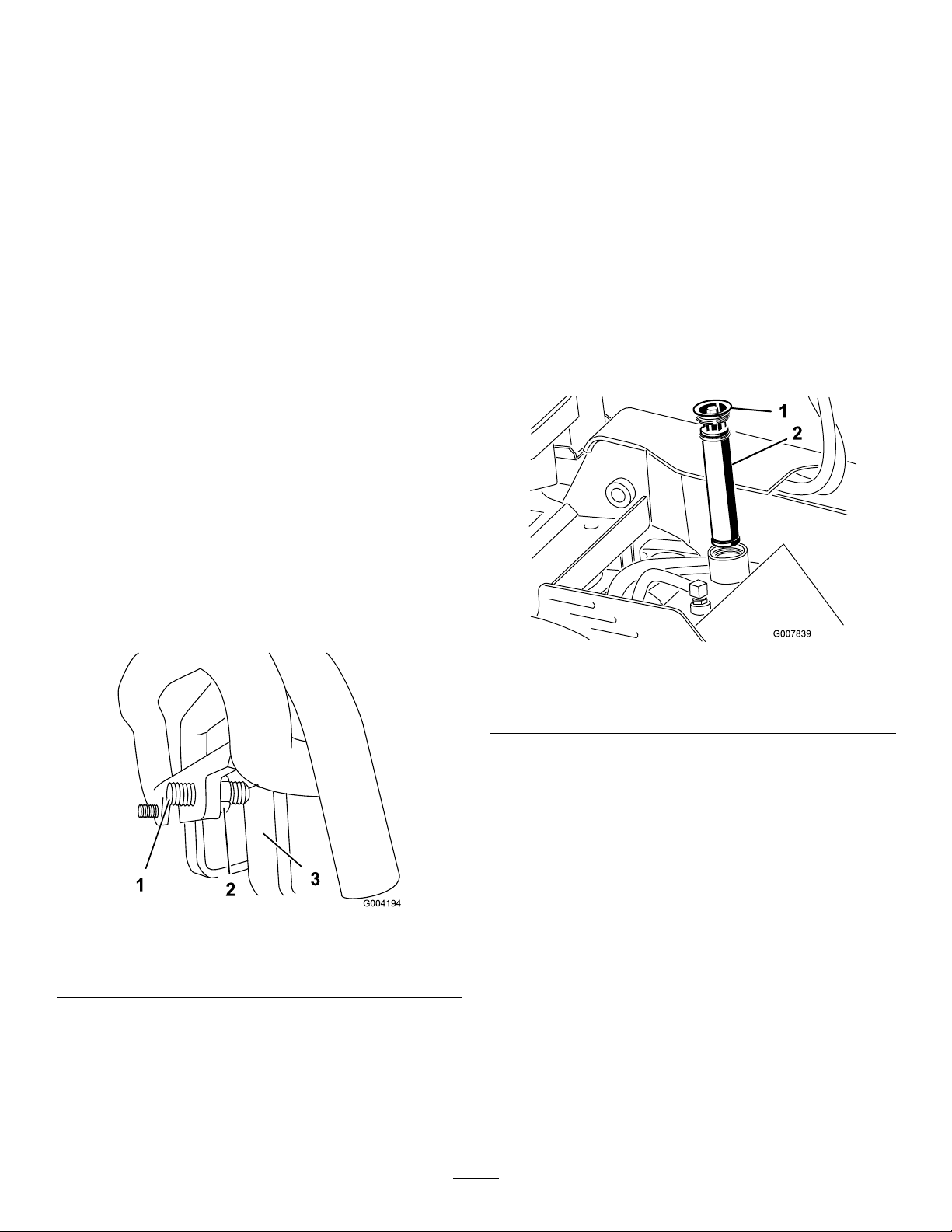
5.Removeanddiscardtheoldlter(
Figure55
1.Fillercap
2.Hydrauliclter
Figure55).
Figure54
1.Setscrew3.Stop
2.Jamnut
5.Repeatsteps1through4untilthemachinedrives
straightinthefullforwardposition.
Important:Ensurethetrackingsetscrews
touchthestopsinthefullforwardpositionto
avoidoverstrokingthehydraulicpumps.
6.Installthereplacementhydrauliclterandllercap
(Figure55)andtorqueboltontopto110to140
in-lb(13to15.5N-m).
7.Cleanupanyspilleduid.
8.Installthetopcover.
ChangingtheHydraulicFluid
ServiceInterval:Every400hours/Yearly(whichever
comesrst)
HydraulicFluidSpecication:
Useonlyoneofthefollowinguidsinthehydraulic
system:
•ToroPremiumTransmission/HydraulicTractor
Fluid(refertoyourAuthorizedToroDealerfor
moreinformation)
35
Page 36
•ToroPremiumAllSeasonHydraulicFluid
(refertoyourAuthorizedToroDealerformore
information)
•IfeitheroftheaboveTorouidsarenot
available,youmayuseanotherUniversalTractor
HydraulicFluid(UTHF),buttheymustbeonly
conventional,petrolium-basedproducts.The
specicationsmustfallwithinthelistedrangefor
allofthefollowingmaterialpropertiesandtheuid
shouldmeetthelistedindustrystandards.Check
withyouroilsuppliertodetermineiftheoilmeets
thesespecications.
Note:Torowillnotassumeresponsibilityfor
damagecausedbyimpropersubstitutions,souse
onlyproductsfromreputablemanufacturerswho
willstandbehindtheirrecommendations.
MaterialProperties
cStat40degreesC:55to62 Viscosity,ASTMD445
cStat100degreesC:9.1to
9.8
Viscosityindex,ASTMD2270
PourPoint,ASTMD97-35to-46degreesF(-37to
IndustryStandards
APIGL-4,AGCOPoweruid821XL,FordNewHolland
FNHA-2-C-201.00,KubotaUDT,JohnDeereJ20C,Vickers
35VQ25andVolvoWB-101/BM.
140to152
-43degreesC)
Figure56
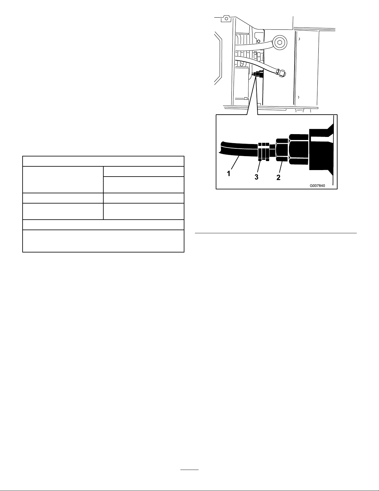
1.Hose
2.Hydraulictanktting
3.Hoseclamp
9.Whennished,installthehoseontothettingand
secureitwiththehoseclamp.
Note:Manyhydraulicuidsarealmostcolorless,
makingitdifculttospotleaks.Areddyeadditive
forthehydraulicsystemoilisavailablein2/3oz(20
ml)bottles.Onebottleissufcientfor4-6gal(15-22
l)ofhydraulicoil.Orderpartno.44-2500fromyour
AuthorizedToroDealer.
1.Positionthemachineonalevelsurface.
2.Lowerthegrinder.
3.Stoptheengine,removethekey,andwaitforall
movingpartstostopbeforeleavingtheoperating
position.
4.Allowthemachinetocoolcompletely .
5.Removethetopcover.
6.Removethehydraulictankllercapandlter
Figure55).
(
7.Placeadrainpancapableofhold10USGallons
(37.8l)underthehydraulictank.
8.Pinchthehoseclampandslidetheclampandhose
offofthettingonthehydraulictank,allowingthe
hydraulicuidtodrainfromthehoseandtankinto
thepan.
Note:Disposeoftheusedoilatacertiedrecycling
center.
10.Fillthehydraulictankwithapproximately6US
gallons(23l)ofhydraulicuidasspeciedpreviously.
11.Add8oz(236ml)ofAMSOIL
®
Slip-Lock™
differentialadditiveoranequivalentdifferential
additivetothehydraulictank.
Note:AMSOILandSlip-Lockaretrademarksof
AMSOILInc.
12.Installthehydrauliclterandllercap(
Figure55)
andtorqueboltontopto110to140in-lb(13to
15.5N-m).
13.Starttheengineandletitrunforafewminutes.
14.Stoptheengine.
15.Checkthehydraulicuidlevelandtopitoffif
necessary;refertoCheckingHydraulicFluid.
16.Cleanupanyspilleduid.
17.Installthetopcover.
36
Page 37
CheckingtheHydraulicLines
ServiceInterval:Every100hours—Checkthehydraulic
linesforleaks,loosettings,kinked
lines,loosemountingsupports,wear,
weather,andchemicaldeterioration
andrepairifnecessary.
Every1,500hours/Every2years
(whichevercomesrst)—Replaceall
movinghydraulichoses.
WARNING
Hydraulicuidescapingunderpressurecan
penetrateskinandcauseinjury.Fluidinjectedinto
theskinmustbesurgicallyremovedwithinafew
hoursbyadoctorfamiliarwiththisformofinjury
organgrenemayresult.
•Keepyourbodyandhandsawayfrompin
holeleaksornozzlesthatejecthighpressure
hydraulicuid.
•Usecardboardorpapertondhydraulicleaks,
neveruseyourhands.
GrinderMaintenance
ReplacingtheTeeth
ServiceInterval:Beforeeachuseordaily—Checkthe
conditionoftheteethandrotateor
replaceanythatarewornordamaged.
Duetothehighamountofwearplacedontheteeth,you
willneedtorotateandreplacethemperiodically.
Figure57
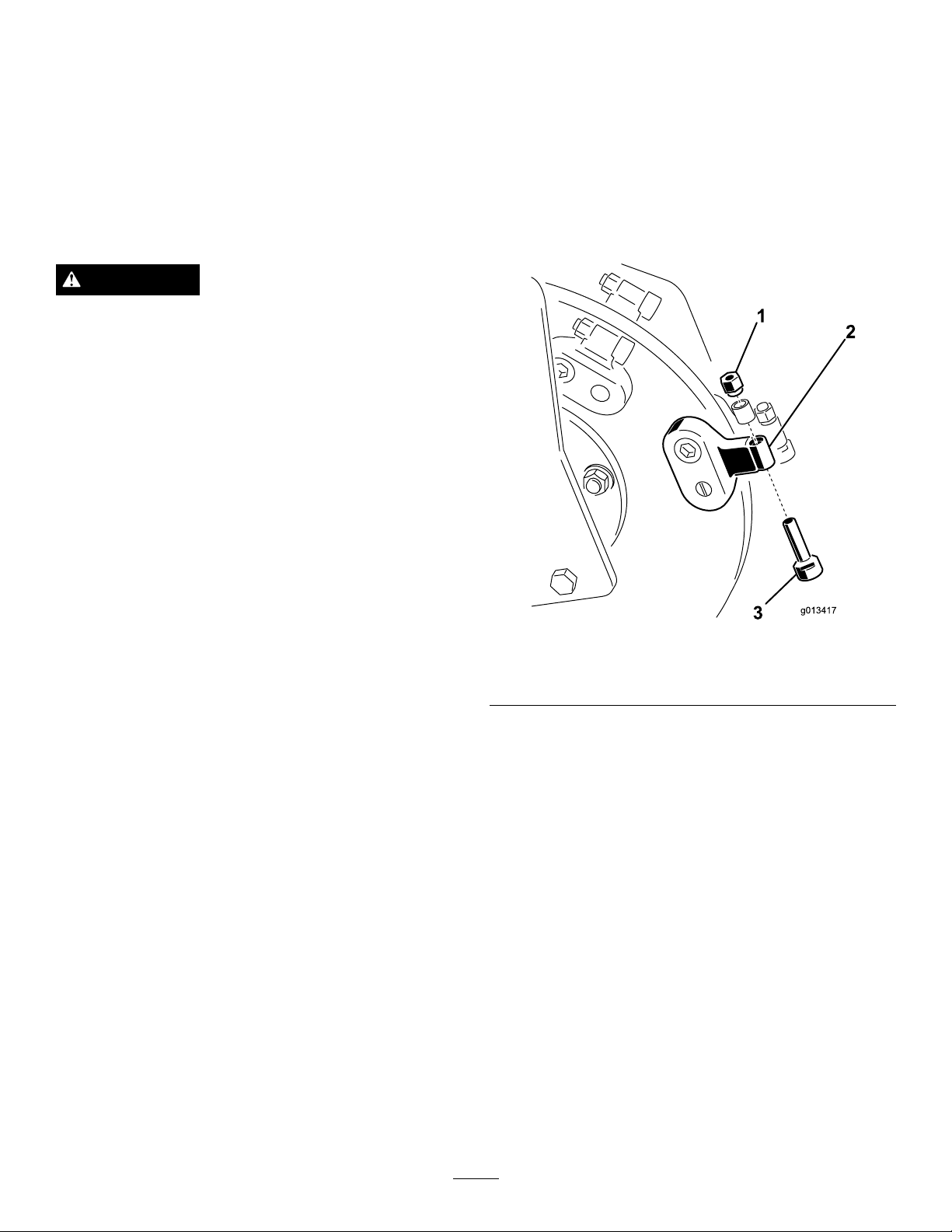
1.Nut3.Tooth
2.Toothholder
Eachtoothisindexedwiththreepositionssoyou
canrotateittwice,exposinganewsharpedgebefore
replacingthetooth.Torotateatooth,loosenthenut
securingthetooth(Figure57).Pushthetoothforward
androtateitonethirdofaturn,bringinganunusededge
totheoutside.Torquethenutsecuringthetooththto27
to33ft-lb(37to45N-m).
Toreplaceatooth,removethenutsecuringthetooth
toremoveit,theninstallanewtoothandnutinthe
sameposition(
tooththto27to33ft-lb(37to45N-m).
Figure57).Torquethenutsecuringthe
37
Page 38

Cleaning
RemovingDebrisfromthe
Machine
Important:Operatingtheenginewithblocked
screens,dirtyorpluggedcoolingns,and/or
coolingshroudsremoved,willresultinengine
damagefromoverheating.
1.Lowerthegrinder.
2.Stoptheengine,removethekey,andwaitforall
movingpartstostopbeforeleavingtheoperating
position.
3.Wipeawaydebrisfromtheaircleaner.
4.Cleananydebrisbuild-upontheenginewithabrush
orblower.
Important:Itispreferabletoblowdirtout,
ratherthanwashingitout.Ifwaterisused,
keepitawayfromelectricalitemsandhydraulic
valves.Donotuseahigh-pressurewasher.
High-pressurewashingcandamagethe
electricalsystemandhydraulicvalvesordeplete
grease.
5.Cleandebrisfromtheoilcooler.
Storage
1.Lowerthegrinder.
2.Stoptheengine,removethekey,andwaitforall
movingpartstostopbeforeleavingtheoperating
position.
3.Removedirtandgrimefromtheexternalpartsof
theentiremachine,especiallytheengine.Cleandirt
andchafffromtheoutsideoftheenginecylinder
headnsandblowerhousing.
Important:Youcanwashthemachinewith
milddetergentandwater.Donotpressure
washthemachine.Avoidexcessiveuseof
water,especiallynearthecontrolpanel,engine,
hydraulicpumps,andmotors.
4.Servicetheaircleaner;referto
ServicingtheAirCleaner(page23).
5.Greasethemachine;referto
GreasingtheMachine(page23).
6.Changetheengineoil;referto
ServicingtheEngineOil(page24).
7.Removethesparkplugandchecktheconditionofit;
referto
8.Forstorageover30days,preparethemachineas
follows:
A.Addapetroleumbasedstabilizer/conditioner
ServicingtheSparkPlug(page25).
tofuelinthetank.Followmixinginstructions
fromstabilizermanufacturer.(1oz.perUS
gallon).Donotuseanalcoholbasedstabilizer
(ethanolormethanol).
Note:Fuelstabilizer/conditionerismost
effectivewhenmixedwithfreshgasolineand
usedatalltimes.
B.Runtheenginetodistributeconditionedfuel
throughthefuelsystem(5minutes).
C.Stoptheengine,allowittocoolanddrainthe
fueltankusingapumptypesyphon.
D.Restarttheengineandrunituntilitstops.
E.Choketheengine.
F.Startandruntheengineuntilitwillnotstart
again.
G.Disposeoffuelproperly.Recycleasperlocal
codes.
Important:Donotstorestabilizer/conditioned
gasolineover90days.
9.Withthesparkplugremovedfromtheengine,pour
twotablespoonsofengineoilintothesparkplug
hole.
38
Page 39

10.Placearagoverthesparkplugholetocatchanyoil
spray,thenusethestarterorrecoilhandletocrank
theengineanddistributetheoilinsidethecylinder.
11.Installthesparkplug,butdonotinstallthewireon
thesparkplug.
12.Chargethebattery;referto
ServicingtheBattery(page28).
13.Checkandadjustthetracktension;referto
CheckingandAdjustingtheTrackTension(page30).
14.Checkandtightenallbolts,nuts,andscrews.Repair
orreplaceanypartthatisdamaged.
15.Paintallscratchedorbaremetalsurfaces.Paintis
availablefromyourAuthorizedServiceDealer.
16.Storethemachineinaclean,drygarageorstorage
area.Removethekeyfromtheignitionswitchand
keepitinamemorableplace.
17.Coverthemachinetoprotectitandkeepitclean.
39
Page 40

Troubleshooting
Problem
Thestarterdoesnotcrank.
Theenginewillnotstart,startshard,or
failstokeeprunning.
Enginelosespower.
PossibleCauseCorrectiveAction
1.Thebatteryisdischarged.
2.Theelectricalconnectionsarecorroded
orloose.
3.Therelayorswitchisdamaged.
1.Thefueltankisempty .1.Fillthefueltankwithgasoline.
2.Thefuelshutoffvalveisclosed.2.Openthefuelshutoffvalve.
3.Thecontrolsarenotinneutral.3.Movethecontrolstoneutral.
4.Thechokeisnoton.
5.Theaircleanerisdirty .
6.Thesparkplugwireislooseor
disconnected.
7.Thesparkplugispitted,fouled,orthe
gapisincorrect.
8.Dirt,water,orstalefuelisinfuel
system.
1.Theengineloadisexcessive.1.Reducegroundspeed.
2.Theaircleanerisdirty .
3.Theoillevelincrankcaseislow.
4.Thecoolingnsandairpassages
undertheengineblowerhousingare
plugged.
5.Thesparkplugispitted,fouled,orthe
gapisincorrect.
6.Dirt,water,orstalefuelisinfuel
system.
1.Chargethebatteryorreplaceit.
2.Checktheelectricalconnectionsfor
goodcontact.
3.ContactyourAuthorizedService
Dealer.
4.Movethechokeleverfullyforward.
5.Cleanorreplacetheaircleaner
elements.
6.Installthewireonthesparkplug.
7.Installanew,correctlygappedspark
plug.
8.ContactyourAuthorizedService
Dealer.
2.Cleanorreplacetheaircleaner
elements.
3.Checkandaddoiltothecrankcase.
4.Removeanyobstructionsfromthe
coolingnsandairpassages.
5.Installanew,correctlygappedspark
plug.
6.ContactyourAuthorizedService
Dealer.
Theengineoverheats.
Abnormalvibration.1.Theenginemountingboltsareloose.1.Tightentheenginemountingbolts.
Themachinedoesnotdrive.
Thegrinderdoesnotturn
Thegrinderdoesnotcutfastenough
1.Theengineloadisexcessive.1.Reducegroundspeed.
2.Theoillevelincrankcaseislow.
3.Thecoolingnsandairpassages
undertheengineblowerhousingare
plugged.
1.Thehydraulicuidlevelislow.1.Checkandaddhydraulicuid.
2.Thetowvalvesareopen.
3.Thehydraulicsystemisdamaged.
1.Achunkofwoodorarockiscaughtin
thegrinder.
2.Thegrinderdrivesystemisdamaged.
3.Thehydraulicsystemisobstructed,
contaminated,ordamaged.
1.Theteethareworn.1.Rotateorreplacetheteeth.
2.Thehydraulicsystemisoverheated.
3.Thehydraulicsystemisobstructed,
contaminated,ordamaged.
2.Checkandaddoiltothecrankcase.
3.Removeanyobstructionsfromthe
coolingnsandairpassages.
2.Closethetowvalves.
3.ContactyourAuthorizedService
Dealer.
1.Stoptheengineandremovethe
obstructionwithastick.
2.ContactyourAuthorizedService
Dealer.
3.ContactyourAuthorizedService
Dealer.
2.Shutdownandallowthesystemtocool.
3.ContactyourAuthorizedService
Dealer.
40
Page 41
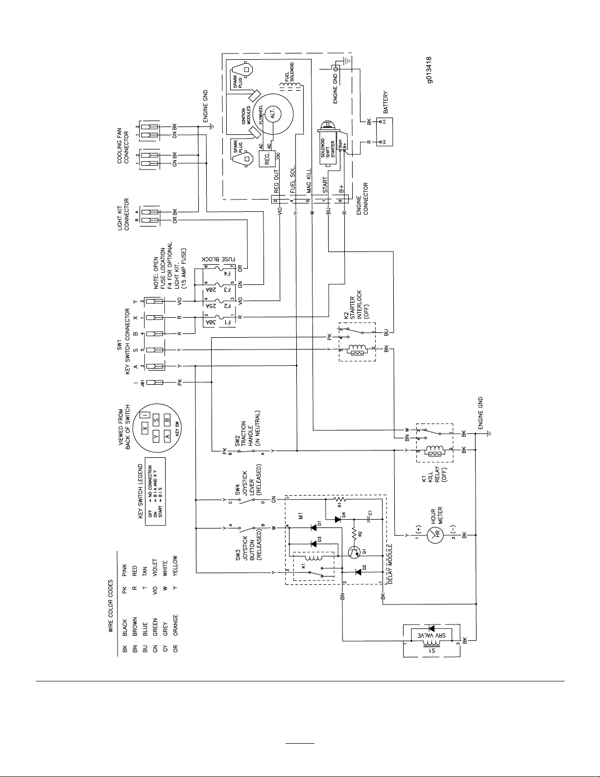
Schematics
g013418
ElectricalSchematic(Rev.A)
41
Page 42
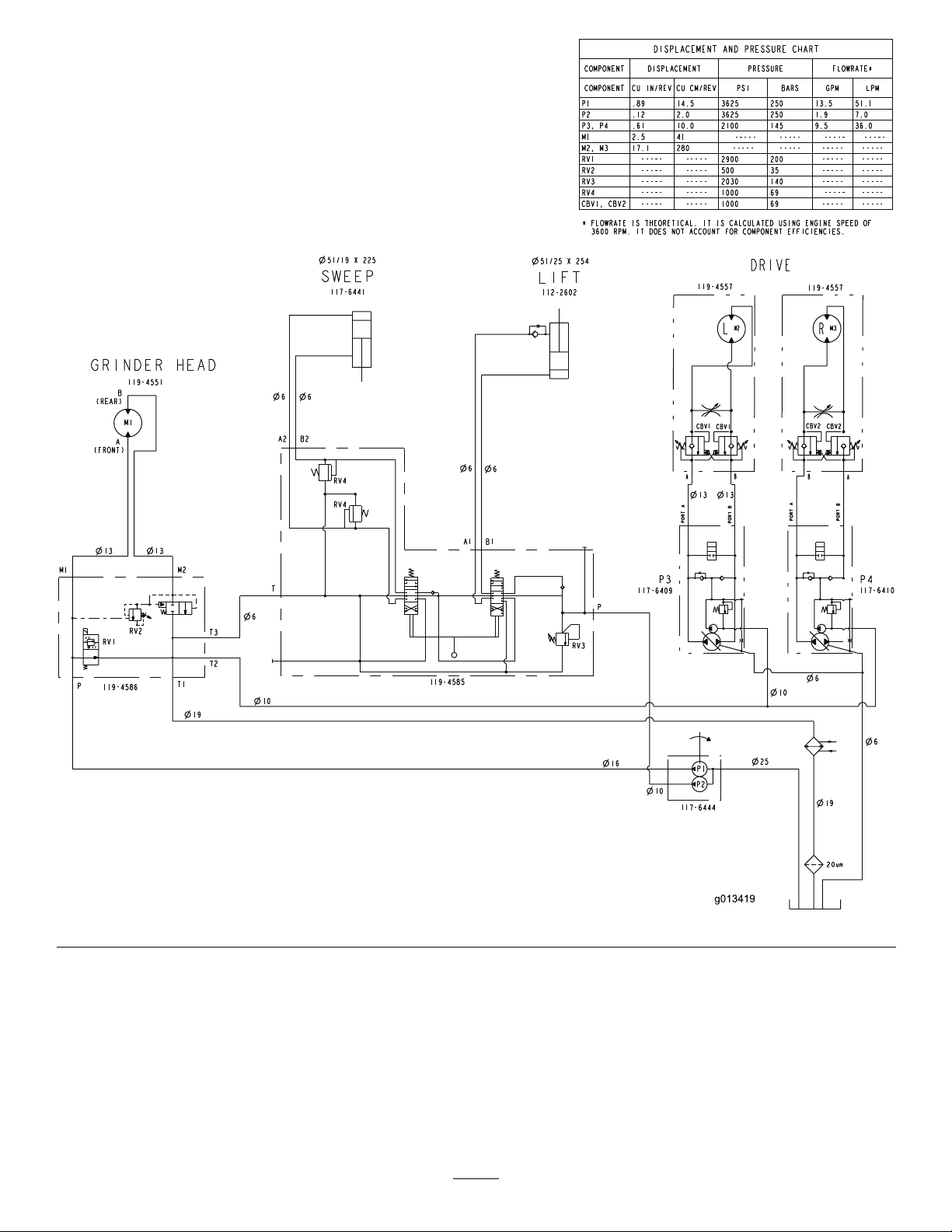
g013419
HydraulicSchematic(Rev.A)
42
Page 43

Notes:
43
Page 44

ToroCompactUtilityEquipmentWarranty
AOne-YearLimitedWarranty
CUEProducts
ConditionsandProductsCovered
TheToro®Companyanditsafliate,T oroWarrantyCompany,pursuant
toanagreementbetweenthem,jointlywarrantyourT oroCompactUtility
Equipment(“Product”)tobefreefromdefectsinmaterialsorworkmanship.
Thefollowingtimeperiodsapplyfromthedateofpurchase:
ProductsWarrantyPeriod
Loaders,Trenchers,StumpGrinders,
Chippers,LogSplittersandAttachments
KohlerEngines3years
AllotherEngines2years
Whereawarrantableconditionexists,wewillrepairtheProductatnocost
toyouincludingdiagnosis,labor,andparts.
1yearor1000operating
hours,whicheveroccursrst
InstructionsforObtainingWarrantyService
IfyouthinkthatyourT oroProductcontainsadefectinmaterialsor
workmanship,followthisprocedure:
1.ContactanyAuthorizedT oroCompactUtilityEquipment(CUE)
ServiceDealertoarrangeserviceattheirdealership.T olocatea
dealerconvenienttoyou,accessourwebsiteatwww.T oro.com.
YoumayalsocallourT oroCustomerCareDepartmenttollfree
at888-865-5676(U.S.customers)or888-865-5691(Canadian
customers).
2.Bringtheproductandyourproofofpurchase(salesreceipt)tothe
ServiceDealer.
3.IfforanyreasonyouaredissatisedwiththeServiceDealer’s
analysisorwiththeassistanceprovided,contactusat:
LCBCustomerCareDepartment
ToroWarrantyCompany
811 1LyndaleAvenueSouth
Bloomington,MN55420-1196
TollFree:888-865-5676(U.S.customers)
TollFree:888-865-5691(Canadacustomers)
OwnerResponsibilities
YoumustmaintainyourT oroProductbyfollowingthemaintenance
proceduresdescribedintheOperator’sManual.Suchroutine
maintenance,whetherperformedbyadealerorbyyou,isatyourexpense.
Partsscheduledforreplacementasrequiredmaintenance(“Maintenance
Parts”),arewarrantedfortheperiodoftimeuptothescheduled
replacementtimeforthatpart.Failuretoperformrequiredmaintenance
andadjustmentscanbegroundsfordisallowingawarrantyclaim.
ItemsandConditionsNotCovered
Notallproductfailuresormalfunctionsthatoccurduringthewarranty
periodaredefectsinmaterialsorworkmanship.Thisexpresswarranty
doesnotcoverthefollowing:
•Productfailureswhichresultfromtheuseofnon-Tororeplacement
parts,orfrominstallationanduseofadd-on,modied,orunapproved
accessories
•Productfailureswhichresultfromfailuretoperformrequired
maintenanceand/oradjustments
•ProductfailureswhichresultfromoperatingtheProductinan
abusive,negligentorrecklessmanner
•Partssubjecttoconsumptionthroughuseunlessfoundtobe
defective.Examplesofpartswhichareconsumed,orusedup,during
normalProductoperationinclude,butarenotlimitedto,teeth,tines,
blades,sparkplugs,tires,tracks,lters,chains,etc.
•Failurescausedbyoutsideinuence.Itemsconsideredtobeoutside
inuenceinclude,butarenotlimitedto,weather,storagepractices,
contamination,useofunapprovedcoolants,lubricants,additives,or
chemicals,etc.
•Normal“wearandtear”items.Normal“wearandtear”includes,butis
notlimitedto,wornpaintedsurfaces,scratcheddecalsorwindows,
etc.
•Anycomponentcoveredbyaseparatemanufacturer’swarranty
•Pickupanddeliverycharges
GeneralConditions
RepairbyanAuthorizedT oroCompactUtilityEquipment(CUE)Service
Dealerisyoursoleremedyunderthiswarranty.
NeitherTheToro®CompanynorToroWarrantyCompanyisliable
forindirect,incidentalorconsequentialdamagesinconnectionwith
theuseoftheToroProductscoveredbythiswarranty,including
anycostorexpenseofprovidingsubstituteequipmentorservice
duringreasonableperiodsofmalfunctionornon-usepending
completionofrepairsunderthiswarranty.Allimpliedwarranties
ofmerchantabilityandtnessforusearelimitedtotheduration
ofthisexpresswarranty .Somestatesdonotallowexclusionsof
incidentalorconsequentialdamages,orlimitationsonhowlong
animpliedwarrantylasts,sotheaboveexclusionsandlimitations
maynotapplytoyou.
Thiswarrantygivesyouspeciclegalrights,andyoumayalsohaveother
rightswhichvaryfromstatetostate.
ExceptfortheenginewarrantycoverageandtheEmissionswarranty
referencedbelow,ifapplicable,thereisnootherexpresswarranty.The
EmissionsControlSystemonyourProductmaybecoveredbyaseparate
warrantymeetingrequirementsestablishedbytheU.S.Environmental
ProtectionAgency(EPA)ortheCaliforniaAirResourcesBoard(CARB).
ThehourlimitationssetforthabovedonotapplytotheEmissions
ControlSystemWarranty .RefertotheCaliforniaEmissionControl
WarrantyStatementsuppliedwithyourProductorcontainedintheengine
manufacturer’sdocumentationfordetails.
CountriesOtherthantheUnitedStatesorCanada
CustomerswhohavepurchasedT oroproductsexportedfromtheUnitedStatesorCanadashouldcontacttheirT oroDistributor(Dealer)toobtain
guaranteepoliciesforyourcountry ,province,orstate.IfforanyreasonyouaredissatisedwithyourDistributor’sserviceorhavedifcultyobtaining
guaranteeinformation,contacttheToroimporter.Ifallotherremediesfail,youmaycontactusatT oroWarrantyCompany .
374-0261RevB
 Loading...