

Page 1

FormNo.3381-505RevA
TimeCutter
®
SS4216Riding
Mower
ModelNo.74616—SerialNo.314000001andUp
Registeratwww.T oro.com.
OriginalInstructions(EN)
*3381-505*A
Page 2
Thismachineisaride-on,rotary-bladelawnmowerintended
G014523
1
tobeusedbyhomeownersinresidentialapplications.Itis
primarilydesignedforcuttinggrassonwell-maintainedlawns.
Itisnotdesignedforcuttingbrush,mowinggrassandother
growthalongsidehighways,orforagriculturaluses.
Important:Thisengineisnotequippedwithaspark
arrestermufer.ItisaviolationofCaliforniaPublic
ResourceCodeSection4442touseoroperatetheengine
onanyforest-covered,brush-covered,orgrass-covered
land.Otherstatesorfederalareasmayhavesimilarlaws.
ThissparkignitionsystemcomplieswithCanadianICES-002.
WARNING
CALIFORNIA
Proposition65Warning
Thisproductcontainsachemicalorchemicals
knowntotheStateofCaliforniatocausecancer,
birthdefects,orreproductiveharm.
Theengineexhaustfromthisproduct
containschemicalsknowntotheStateof
Californiatocausecancer,birthdefects,
orotherreproductiveharm.
Introduction
Readthisinformationcarefullytolearnhowtooperateand
maintainyourproductproperlyandtoavoidinjuryand
productdamage.Youareresponsibleforoperatingthe
productproperlyandsafely .
YoumaycontactTorodirectlyatwww .Toro.comforproduct
andaccessoryinformation,helpndingadealer,ortoregister
yourproduct.
Wheneveryouneedservice,genuineToroparts,oradditional
information,contactanAuthorizedServiceDealerorToro
CustomerServiceandhavethemodelandserialnumbersof
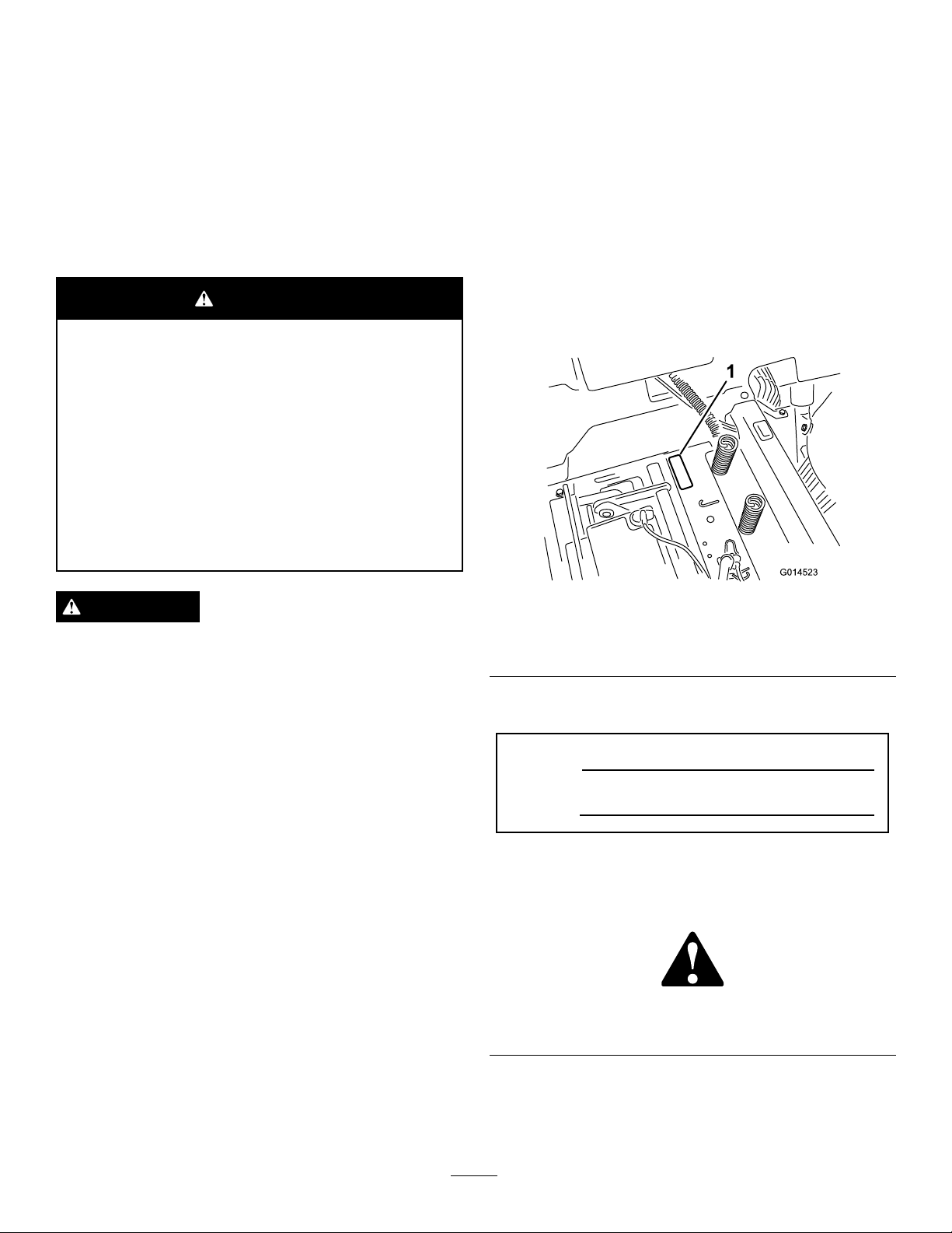
yourproductready .Figure1identiesthelocationofthe
modelandserialnumbersontheproduct.Writethenumbers
inthespaceprovided.
WARNING
Removingstandardoriginalequipmentpartsand
accessoriesmayalterthewarranty,traction,and
safetyofthemachine.FailuretouseoriginalToro
partscouldcauseseriousinjuryordeath.Making
unauthorizedchangestotheengine,fuelorventing
system,mayviolateEPAandCARBregulations.
Replaceallpartsincluding,butnotlimitedto,tires,
belts,blades,andfuelsystemcomponentswith
originalT oroparts.
GrossHorsepower
Thegrossornethorsepowerofthisenginewaslaboratory
ratedbytheenginemanufacturerinaccordancewiththe
SocietyofAutomotiveEngineers(SAE)J1940.Ascongured
tomeetsafety ,emission,andoperatingrequirements,
theactualenginetorqueonthisclassofmowerwillbe
signicantlylower.
Gotowww.Toro.comtoviewspecicationsonyourmower
model.
Figure1
Undertheseat
1.Modelandserialnumberplate
Writetheproductmodelandserialnumbersinthespace
below:
ModelNo.
SerialNo.
Thismanualidentiespotentialhazardsandhassafety
messagesidentiedbythesafetyalertsymbol(Figure2),
whichsignalsahazardthatmaycauseseriousinjuryordeath
ifyoudonotfollowtherecommendedprecautions.
Figure2
1.Safetyalertsymbol.
©2013—TheToro®Company
8111LyndaleAvenueSouth
Bloomington,MN55420
Thismanualusestwowordstohighlightinformation.
Importantcallsattentiontospecialmechanicalinformation
andNoteemphasizesgeneralinformationworthyofspecial
attention.
Contactusatwww.T oro.com.
2
PrintedintheUSA
AllRightsReserved
Page 3

Contents
Introduction..................................................................2
Safety...........................................................................4
SafeOperatingPractices...........................................4
ToroRidingMowerSafety........................................6
SlopeIndicator.......................................................7
SafetyandInstructionalDecals.................................8
ProductOverview.........................................................11
Controls...............................................................11
Operation....................................................................13
ThinkSafetyFirst...................................................13
BeforeStarting.......................................................14
StartingtheEngine.................................................15
OperatingtheBlades...............................................16
TestingtheSafetyInterlockSystem...........................17
StoppingtheEngine...............................................17
Driving.................................................................17
StoppingtheMachine.............................................19
AdjustingtheHeightofCut.....................................19
AdjustingtheAnti-ScalpRollers...............................19
PositioningtheSeat................................................20
AdjustingtheMotionControlLevers........................20
PushingtheMachinebyHand..................................20
GrassDeector......................................................21
OperatingTips......................................................21
Maintenance.................................................................23
RecommendedMaintenanceSchedule(s)......................23
PremaintenanceProcedures........................................23
RaisingtheSeat......................................................23
Lubrication...............................................................23
GreasingtheBearings.............................................23
EngineMaintenance..................................................24
ServicingtheAirCleaner.........................................24
ServicingtheEngineOil..........................................25
ServicingtheSparkPlug..........................................26
FuelSystemMaintenance...........................................28
ReplacingtheIn-lineFuelFilter................................28
ElectricalSystemMaintenance....................................29
ChargingtheBattery...............................................29
ServicingtheFuses.................................................30
DriveSystemMaintenance.........................................31
CheckingtheTirePressure......................................31
ReleasingtheElectricBrake.....................................31
CoolingSystemMaintenance......................................32
CleaningtheEngineScreen......................................32
CleaningtheEngineCoolingFinsand
Shrouds.............................................................32
MowerMaintenance...................................................32
ServicingtheCuttingBlades.....................................32
LevelingtheMowerDeck........................................35
RemovingtheMower..............................................37
MowerBeltMaintenance.........................................37
InstallingtheMower...............................................38
ReplacingtheGrassDeector..................................38
Cleaning...................................................................39
WashingtheUndersideoftheMower........................39
Storage........................................................................40
CleaningandStorage..............................................40
Troubleshooting...........................................................41
Schematics...................................................................43
3
Page 4

Safety
Toreducethepotentialforinjury,complywiththese
safetyinstructionsandalwayspayattentiontothesafety
alertsymbol,whichmeansCAUTION,WARNING,
orDANGER-"personalsafetyinstruction."Failure
tocomplywiththeinstructionmayresultinpersonal
injuryordeath.
•Turnoffbladeswhennotmowing.Stoptheengine,wait
forallpartstocometoacompletestopandremovethe
keybeforecleaningthemachine,removingthegrass
catcheroruncloggingthedischargechute.
•Operatethemachineonlyindaylightorgoodarticial
light.
•Donotoperatethemachinewhileundertheinuence
ofalcoholordrugs.
SafeOperatingPractices
Thisproductiscapableofamputatinghandsandfeetand
throwingobjects.Alwaysfollowallsafetyinstructionsto
avoidseriousinjuryordeath.
ThefollowinginstructionsareadaptedfromANSIstandard
B71.1-2012.AllthelanguagewithinthisANSIstandard
appliestothismachine;however,duetotheapplicationof
thestandardacrossmanydifferenttypesofproductssome
statementscanseemgeneralormisleading.Intheseinstances,
Torohasrenedthestatementtoconveythemeaningofthe
standardwhilebettermatchingtheproductthisOperator's
Manualpertains.Safetyinformationinadditiontothe
instructionsfoundintheANSIstandardbelowcanbefound
inToroRidingMowerSafetyattheendofthissection.
GeneralOperation
•Read,understand,andfollowallinstructionsinthe
operator'smanualandonthemachinebeforestarting.
•Donotplacehandsorfeetnearrotatingpartsorunder
themachine.Keepclearofthedischargeopeningatall
times.
•Allowonlyresponsibleadultswhoarefamiliarwiththe
instructionstooperatethemachine.
•Cleartheareaofobjectssuchasrocks,toys,wire,etc.,
whichcouldbepickedupandthrownbytheblade.
•Besuretheareaisclearofotherpeoplebeforemowing.
Stopthemachineifanyoneentersthearea.
•Nevercarrypassengers.
•Donotmowinreverseunlessabsolutelynecessary.
Alwayslookdownandbehindbeforeandwhilebacking
up.
•Beawareofthemowerdischargedirectionanddonot
pointitatanyone.Avoiddischargingmaterialagainsta
wallorobstruction.Materialmayricochetbacktoward
theoperator.Stoptheblade(s)whencrossinggravel
surfaces.
•Donotoperatethemachinewithoutdeector,discharge
coverorentiregrasscollectionsysteminplaceand
working.
•Bealert,slowdownandusecautionwhenmakingturns.
Lookbehindandtothesidebeforechangingdirections.
•Neverleavearunningmachineunattended.Alwaysturn
offblades,setparkingbrake,stopengine,andremovekey
beforedismounting.
•Watchfortrafcwhenoperatingnearorcrossing
roadways.
•Useextracarewhenloadingorunloadingthemachine
intoatrailerortruck.
•Alwaysweareyeprotectionwhenoperatingthemower.
•Dataindicatesthatoperators,age60yearsandabove,are
involvedinalargepercentageofridingmower-related
injuries.Operatorsshouldevaluatetheirabilitytooperate
theridingmowersafelyenoughtoprotectthemselvesand
othersfromseriousinjury.
•Alwaysfollowtherecommendationsforanyapplication
ofcounterweights.
•Lightningcancausesevereinjuryordeath.Iflightning
isseenorthunderisheardinthearea,donotoperate
themachine;seekshelter.
SlopeOperation
Slopesareamajorfactorrelatedtolossofcontroland
tip-overaccidents,whichcanresultinsevereinjuryordeath.
Operationonallslopesrequiresextracaution.Ifyoucannot
backuptheslopeorifyoufeeluneasyonit,donotmowit.
•Donotmowslopesgreaterthan15degrees.
•Watchforditches,holes,rocks,dips,andrisesthatchange
theoperatingangle,asroughterraincouldoverturnthe
machine.
•Choosealowgroundspeedsoyouwillnothavetostop
whileoperatingonaslope.
•Donotmowslopeswhengrassiswet.Slippery
conditionsreducetractionandcouldcauseslidingand
lossofcontrol.
•Alwayskeepthedrivewheelsengagedwhengoingdown
slopes.
•Reducespeedanduseextremecautiononslopes.
•Donotmakesuddenturnsorrapidspeedchanges.
•Removeormarkobstaclessuchasrocks,treelimbs,etc.
fromthemowingarea.Tallgrasscanhideobstacles.
•Avoidsuddenstartswhenmowinguphillbecausethe
mowermaytipbackwards.
•Beawarethatlossoftractionmayoccurgoingdownhill.
Weighttransfertothefrontwheelsmaycausedrive
wheelstoslipandcauselossofbrakingandsteering.
4
Page 5

•Alwaysavoidsuddenstartingorstoppingonaslope.If
tireslosetraction,stopthemachine,disengagetheblades
andproceedslowlyofftheslope.
•Useextremecarewithgrasscatchersorotherattachments.
Thesecanchangethestabilityofthemachineandcause
lossofcontrol.
•Donottrytostabilizethemachinebyputtingyourfoot
ontheground.
•Donotmowneardrop-offs,ditches,steepbanksor
water.Wheelsdroppingoveredgescancauserollovers,
whichmayresultinseriousinjury,deathordrowning.
•Useawalkbehindmowerand/orahandtrimmernear
drop-offs,ditches,steepbanksorwater.
Children
Tragicaccidentscanoccuriftheoperatorisnotalerttothe
presenceofchildren.Childrenareoftenattractedtothe
machineandthemowingactivity.Neverassumethatchildren
willremainwhereyoulastsawthem.
•Keepchildrenoutofthemowingareaandunderthe
watchfulcareofanotherresponsibleadult,notthe
operator.
•Bealertandturnthemachineoffifchildrenenterthe
area.
•Beforeandwhilebackingorchangingdirection,look
behind,down,andside-to-sideforsmallchildren.
•Nevercarrychildren,evenwiththebladesoff.Theymay
falloffandbeseriouslyinjuredorinterferewithsafe
machineoperation.
•Childrenwhohavebeengivenridesinthepastmay
suddenlyappearinthemowingareaforanotherrideand
berunoverorbackedoverbythemower.
•Neverallowchildrentooperatethemachine.
•Useextracarewhenapproachingblindcorners,shrubs,
trees,theendofafenceorotherobjectsthatmayobscure
vision.
TowingSafety
•Donotattachtowedequipmentexceptatthehitchpoint.
•Followtheattachmentmanufacturer'srecommendation
forweightlimitsfortowedequipmentandtowingon
slopes.Towedweightmustnotexceedtheweightofthe
machine,operator,andballast.Usecounterweightsor
wheelweightsasdescribedintheattachment,orinthe
pullingmachineOperator’sManual.
•Neverallowchildrenorothersinorontowedequipment.
•Onslopes,theweightofthetowedequipmentmaycause
lossoftraction,increasedriskofrollover,andlossof
control.Reducethetowedweightandslowdown.
•Stoppingdistanceincreaseswiththeweightofthetowed
load.Travelslowlyandallowextradistancetostop.
•Makewideturnstokeeptheattachmentclearofthe
machine.
Service
SafeHandlingofGasoline:
Toavoidpersonalinjuryorpropertydamage,useextracare
whenhandlinggasolineandotherfuels.Theyareammable
andthevaporsareexplosive.
•Extinguishallcigarettes,cigars,pipesandothersources
ofignition.
•Useonlyanapprovedcontainer.
•Neverremovethegascaporaddfuelwhentheengineis
running.Allowtheenginetocoolbeforerefueling.
•Neverrefuelthemachineindoors.
•Neverstorethemachineorfuelcontainerinsidewhere
thereisanopename,suchasnearawaterheateror
furnace.
•Neverllcontainersinsideavehicleoronatruckor
trailerwithaplasticliner.Alwaysplacecontainersonthe
groundawayfromyourvehiclebeforelling.
•Removegas-poweredequipmentfromthetruckortrailer
andrefuelitontheground.Ifthisisnotpossible,then
refuelsuchequipmentwithaportablecontainer,rather
thanfromagasolinedispensernozzle.
•Keepthenozzleincontactwiththerimofthefueltank
orcontaineropeningatalltimesuntilthefuelingis
complete.Donotuseanozzlelock-opendevice.
•Iffuelisspilledonclothing,changeclothingimmediately.
•Neveroverllthefueltank.Replacegascapandtighten
securely.
GeneralService:
•Neveroperateamachineinsideaclosedarea.Engine
exhaustcontainscarbonmonoxide,whichisanodorless,
deadlypoisonthatcankillyou.
•Keepnutsandboltstight,especiallythebladeattachment
bolts.Keepequipmentingoodcondition.
•Neverinterferewiththeintendedfunctionofasafety
deviceortoreducetheprotectionprovidedbyasafety
device.Checktheirproperoperationregularly.
•Keepthemachinefreeofgrass,leaves,orotherdebris
build-up.Cleanupoilorfuelspillagefuelsoakeddebris.
Allowthemachinetocoolbeforestoring.
•Stopandinspecttheequipmentifyoustrikeanobject.
Repair,ifnecessary,beforerestarting.
•Nevermakeanyadjustmentsorrepairswiththeengine
running.
•Grasscatchercomponentsaresubjecttowear,damage
anddeterioration,whichcouldexposemovingpartsor
allowobjectstobethrown.Frequentlycheckcomponents
andreplacewithmanufacturers'recommendedparts,
whennecessary.
•Mowerbladesaresharpandcancut.Wraptheblade(s)or
weargloves,anduseextracautionwhenservicingthem.
•Checkforproperbrakeoperationfrequently.Adjustand
serviceasrequired.
5
Page 6

•Maintainorreplacesafetyandinstructiondecalsas
necessary.
•UseonlygenuineTororeplacementpartstoensurethat
originalstandardsaremaintained.
ToroRidingMowerSafety
ThefollowinglistcontainssafetyinformationspecictoToro
productsorothersafetyinformationthatyoumustknowthat
maynotbeincludedintheANSIstandards.
•Stoptheengine,movethemotioncontrolleversto
neutralandoutwardtotheparkposition,disengagethe
bladecontrolswitch,removethekeyanddisconnectthe
sparkplugwire(s)beforeperforminganyservice,repairs,
maintenanceoradjustments.
•Keephands,feet,hair,andlooseclothingawayfrom
attachmentdischargearea,undersideofmowerandany
movingpartswhileengineisrunning.
•Donottouchequipmentorattachmentpartswhichmay
behotfromoperation.Allowtocoolbeforeattempting
tomaintain,adjustorservice.
•Batteryacidispoisonousandcancauseburns.Avoid
contactwithskin,eyes,andclothing.Protectyourface,
eyes,andclothingwhenworkingwithabattery.
•Batterygasescanexplode.Keepcigarettes,sparksand
amesawayfrombattery.
•UseonlyToroapprovedattachments.Warrantymaybe
voidedifusedwithunapprovedattachments.
•Ifloadingthemachineontoatrailerortruck,useasingle,
full-widthramponly.Therampangleshouldnotexceed
15degrees.
6
Page 7
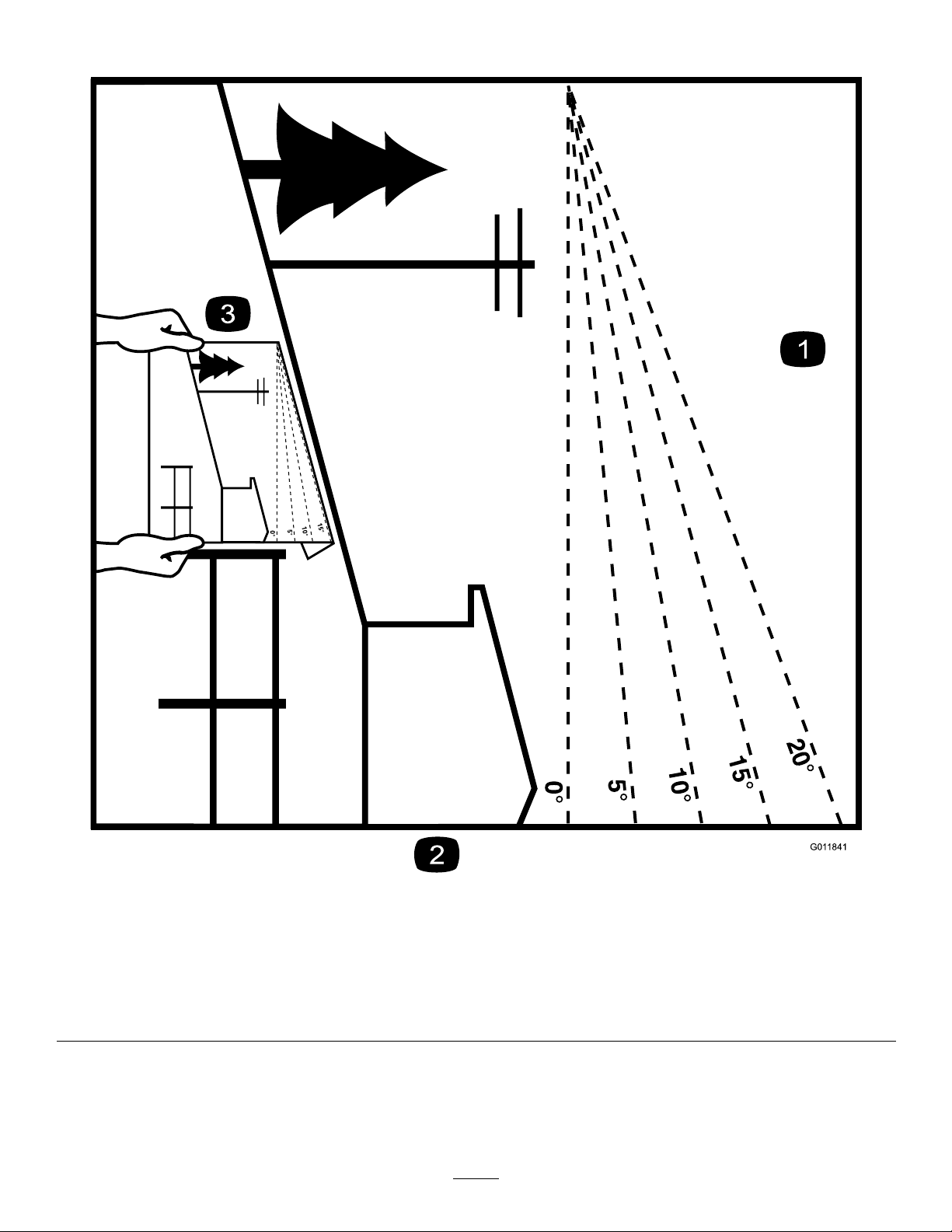
SlopeIndicator
G011841
Figure3
Thispagemaybecopiedforpersonaluse.
1.Themaximumslopeyoucansafelyoperatethemachineonis15degrees.Usetheslopecharttodeterminethedegreeofslope
ofhillsbeforeoperating.Donotoperatethismachineonaslopegreaterthan15degrees.Foldalongtheappropriateline
tomatchtherecommendedslope.
2.Alignthisedgewithaverticalsurface,atree,building,fencepole,etc.
3.Exampleofhowtocompareslopewithfoldededge.
7
Page 8
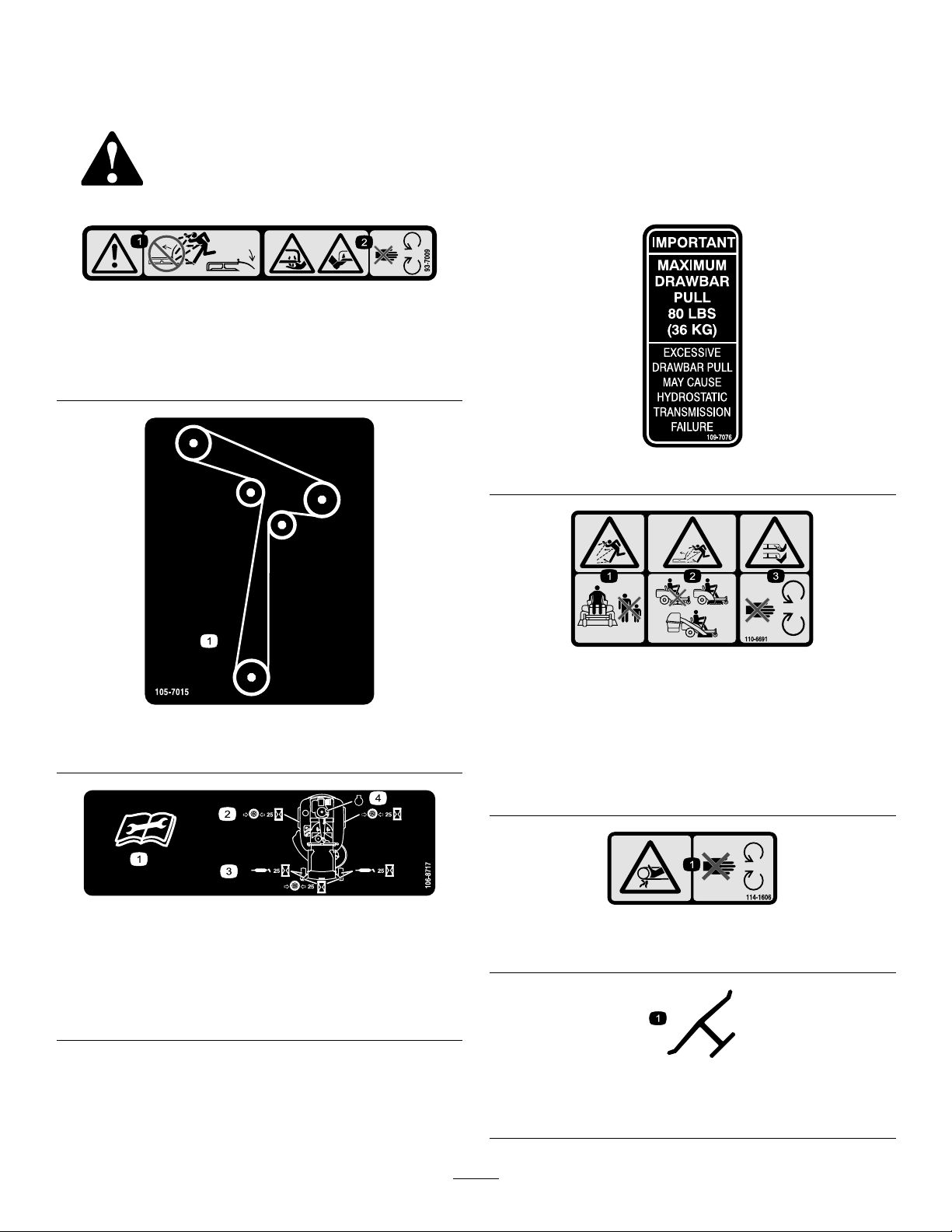
SafetyandInstructional
Decals
Safetydecalsandinstructionsareeasilyvisibletotheoperatorandarelocatednearanyareaofpotential
danger.Replaceanydecalthatisdamagedorlost.
93-7009
1.Warning—don'toperatethemowerwiththedeectorupor
removed;keepthedeectorinplace.
2.Cutting/dismembermenthazardofhandorfoot,mower
blade—stayawayfrommovingparts.
109-7076
105-7015
ForModelswith42InchDecks
106-8717
1.Readtheinstructionsbeforeservicingorperforming
maintenance.
2.Checktirepressureevery25operatinghours.
3.Greaseevery25operatinghours.
4.Engine
110-6691
1.Thrownobjecthazard—keepbystandersasafedistance
fromthemachine.
2.Thrownobjecthazard,mower—donotoperatewithoutthe
deector,dischargecover,orgrasscollectionsystemin
place.
3.Cutting/dismembermentofhandorfoot—stayawayfrom
movingparts.
114-1606
1.Entanglementhazard,belt—keepallguardsinplace.
Manufacturer'sMark
1.Indicatesthebladeisidentiedasapartfromtheoriginal
machinemanufacturer.
8
Page 9
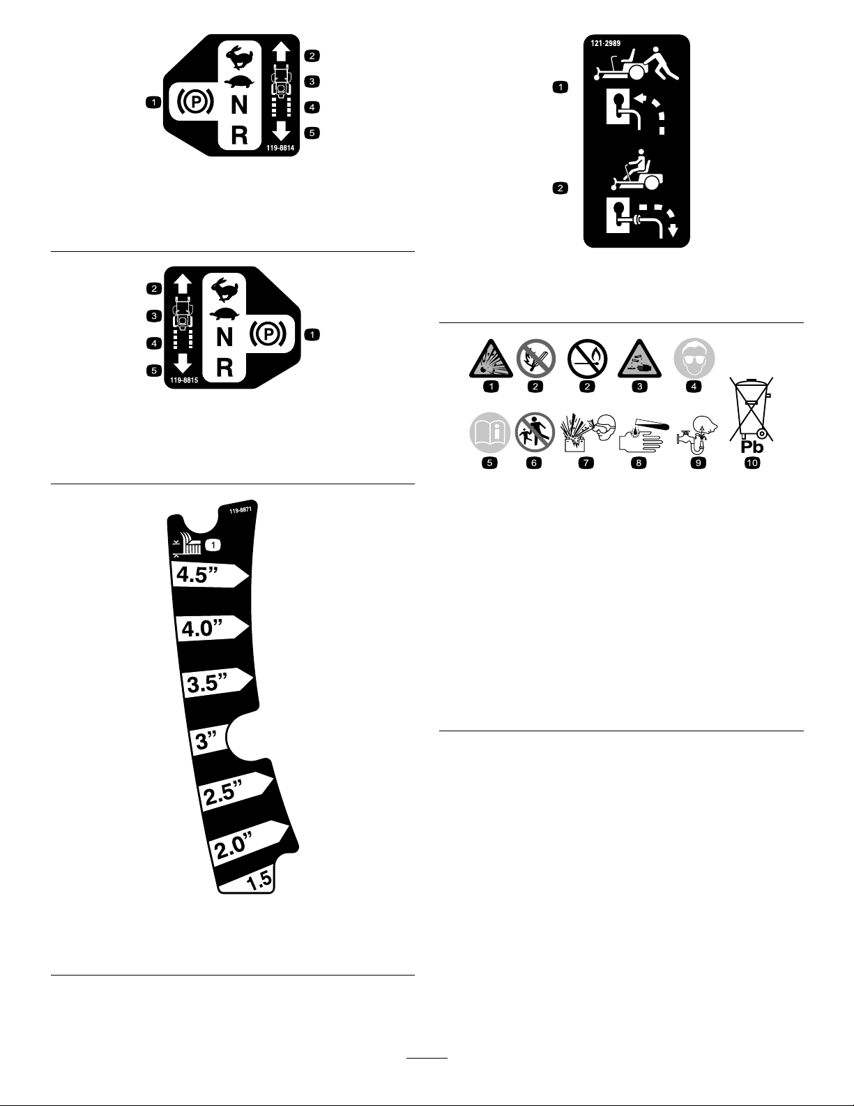
119-8814
1.Parkingposition4.Neutral
2.Fast5.Reverse
3.Slow
121-2989
119-8815
1.Parkingposition4.Neutral
2.Fast5.Reverse
3.Slow
1.Bypassleverpositionfor
pushingthemachine
2.Bypassleverpositionfor
BatterySymbols
Someorallofthesesymbolsareonyourbattery
1.Explosionhazard
2.Nore,opename,or
smoking.
3.Causticliquid/chemical
burnhazard
4.Weareyeprotection9.Flusheyesimmediately
5.ReadtheOperator's
Manual.
6.Keepbystandersasafe
7.Weareyeprotection;
8.Batteryacidcancause
10.Containslead;donot
operatingthemachine
distancefromthebattery .
explosivegasescan
causeblindnessandother
injuries
blindnessorsevereburns.
withwaterandgetmedical
helpfast.
discard.
119-8871
42InchModel
1.Height-of-cut
9
Page 10
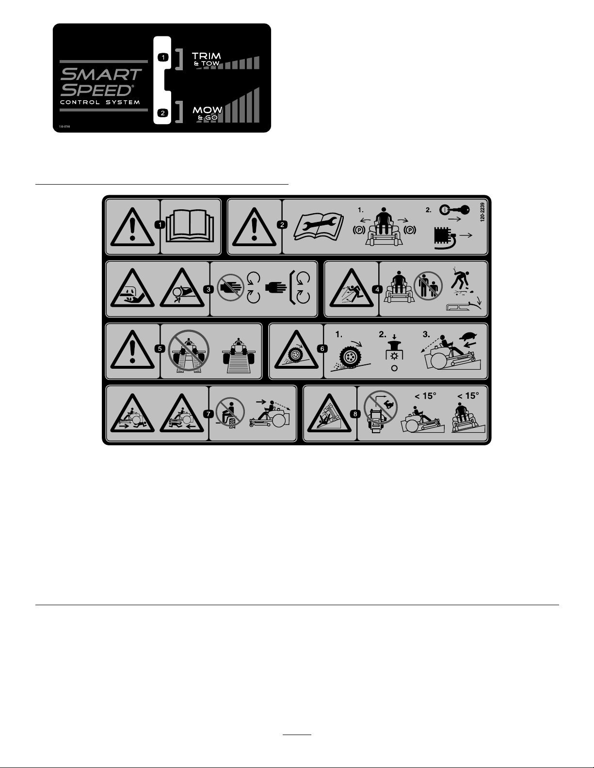
130-0780
1.Lowspeed—trimmingand
towing
2.Highspeed—mowingand
transport
120-2239
1.Warning—readtheOperator'sManual.5.Warning—donotusesplitramps,useafullrampswhen
2.Warning—readtheinstructionsbeforeservicingorperforming
maintenance;movethemotioncontrolleverstothepark
(brake)position,removetheignitionkeyanddisconnectthe
sparkplugwire.
3.Cutting/dismembermenthazard,mowerblade;entanglement
hazard,belt—stayawayfrommovingparts,keepallguards
andshieldsinplace.
4.Thrownobjecthazard—keepbystandersasafedistancefrom
themachine,pickupdebrisbeforeoperating,keepdeector
inplace.
transportingmachine.
6.Lossoftraction/controlhazard,slopes—lossoftraction/control
onaslope,disengagethebladecontrolswitch(PTO),
proceedofftheslopeslowly .
7.Crushing/dismembermenthazardofbystanders,reversing;
crushing/dismembermenthazardofbystanders—donotcarry
passengers,lookbehindanddownwhenreversing.
8.Tippinghazard—donotmowslopesgreaterthan15degrees,
avoidsuddenandsharpturnswhileonslopes.
10
Page 11
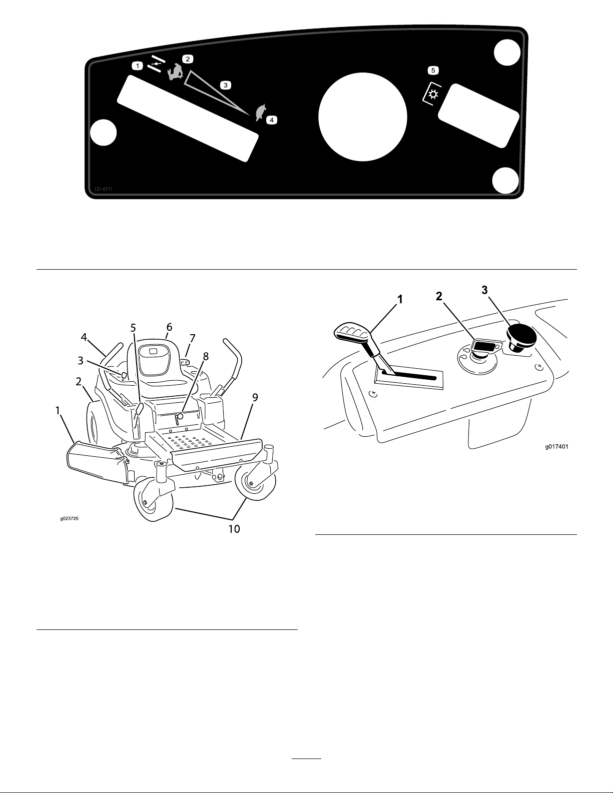
121-0771
1.Choke4.Slow
2.Fast
3.Continuousvariablesetting
ProductOverview
5.Powertake-off(PTO),Bladecontrolswitch
Figure5
ControlPanel
Figure4
1.Deector6.Operatorseat
2.Reardrivewheel7.Fueltankcap
3.Controlpanel8.Smartspeedlever
4.Motioncontrollevers9.Footrest
5.Heightofcutlever
10.Frontcasterwheel
Controls
BecomefamiliarwithallofthecontrolsinFigure4and
Figure5beforeyoustarttheengineandoperatethemachine.
1.Throttle/Choke
2.Ignitionswitch
3.Bladecontrolswitch
(powertake-off)
IgnitionSwitch
Theignitionswitchhasthreepositions,Off,RunandStart.
ThekeywillturntoStartandmovebacktoRunuponrelease.
TurningthekeytotheOffpositionwillstoptheengine;
however,alwaysremovethekeywhenleavingthemachine
topreventsomeonefromaccidentallystartingtheengine
(
Figure5).
Throttle/ChokeControl
Thethrottleandchokeiscombinedintoonecontrollever.
Thethrottlecontrolstheenginespeedandithasacontinuous
variablesettingfromSlowtoFast.Engagethechokeby
movingtheleverpasttheFastsettinguntilitstops(
11
Figure5).
Page 12
BladeControlSwitch(PowerTake-Off)
G014475
1
G014521
1
Thebladecontrolswitch,representedbyapowertake-off
(PTO)symbol,engagesanddisengagespowertothemower
blades(Figure5).
MotionControlLeversandPark
Position
Themotioncontrolleversarespeedsensitivecontrolsof
independentwheelmotors.Movingaleverforwardor
backwardturnsthewheelonthesamesideforwardorin
reverse;wheelspeedisproportionaltotheamountthelever
ismoved.Movethecontrolleversoutwardfromthecenter
totheparkpositionandexitthemachine(Figure16).Always
positionthemotioncontrolleversintotheparkposition
whenyoustopthemachineorleaveitunattended.
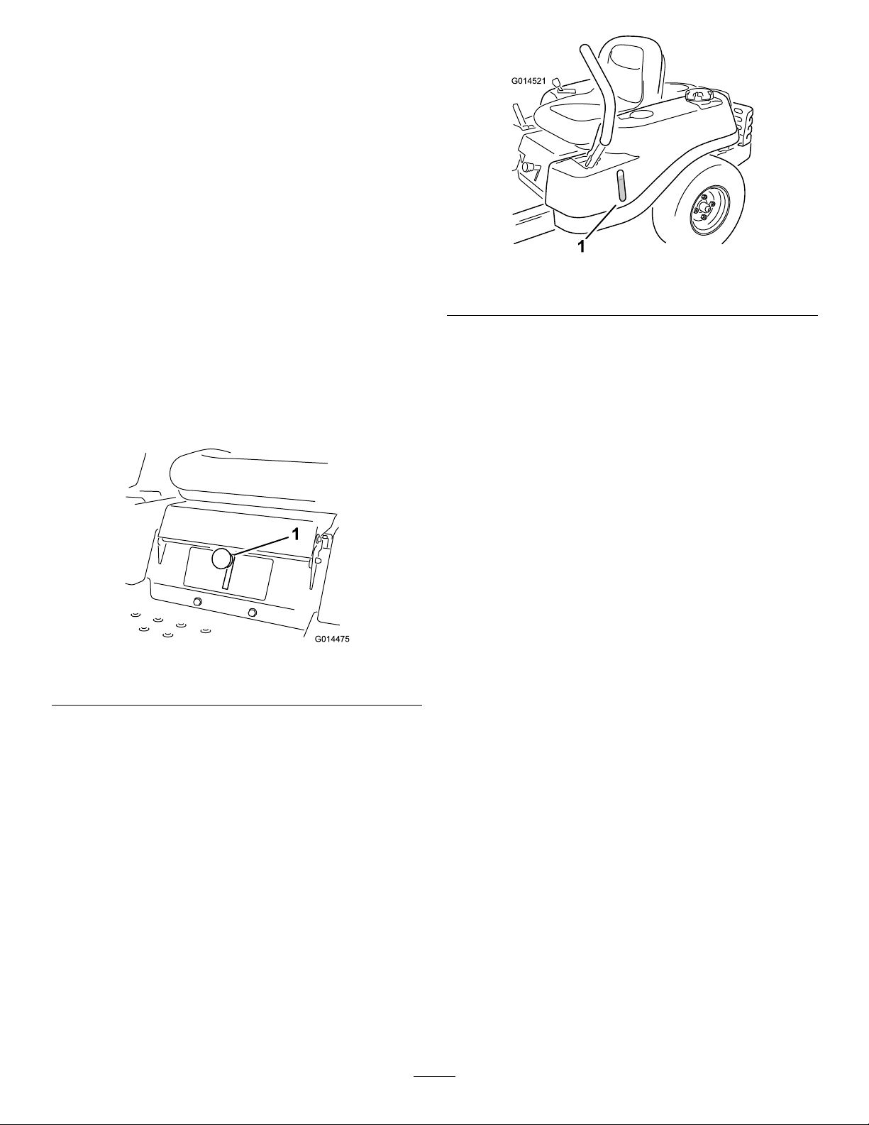
Figure7
1.Fuelpresencewindow
SmartSpeed™ControlSystemLever
TheSmartSpeed™ControlSystemlever,locatedbelowthe
operatingposition,givestheoperatorachoicetodrivethe
machineattwospeedranges,highandlow(Figure6).
Figure6
1.Smartspeedlever
FuelWindow
Height-of-CutLever
Theheightofcutleverallowstheoperatortolowerand
raisethedeckfromtheseatedposition.Whentheleveris
movedup,towardtheoperatorthedeckisraisedfromthe
groundandwhenmoveddown,awayfromtheoperatoritis
loweredtowardtheground.Onlyadjusttheheightofcut
whilemachineisnotmoving(Figure4).
Thefuelwindowlocatedonthelefthandsideofthemachine
canbeusedtoverifythepresenceofgasolineinthetank
(Figure7).
12
Page 13
Operation
Note:Determinetheleftandrightsidesofthemachinefromthenormaloperatingposition.
ThinkSafetyFirst
OperatingSafety
Pleasecarefullyreadallofthesafetyinstructionsanddecals
inthesafetysection.Knowingthisinformationcouldhelp
you,yourfamily,petsorbystandersavoidinjury.
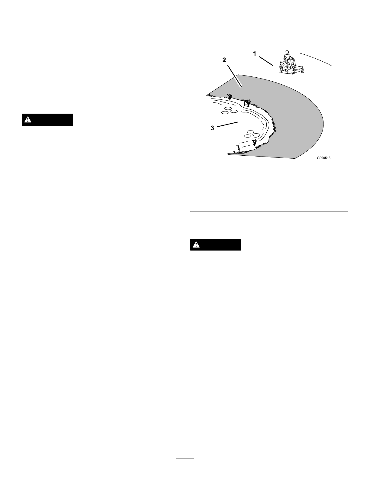
DANGER
Mowingonwetgrassorsteepslopescancause
slidingandlossofcontrol.
Wheelsdroppingoveredgescancauserollovers,
whichmayresultinseriousinjury,deathor
drowning.
Alossoftractionisalossofsteeringcontrol.
Toavoidlossofcontrolandpossibilityofrollover:
•Donotmowneardrop-offsornearwater.
1.SafeZone-usethe
TimeCutterhere
2.Usewalkbehindmower
and/orhandtrimmernear
drop-offsandwater .
Figure8
3.Water
•Donotmowslopesgreaterthan15degrees.
•Reducespeedanduseextremecautionon
slopes.
•Whenmowingslopes,graduallyworkfrom
lowertohigherareasontheincline.
•Avoidsuddenturnsorrapidspeedchanges.
•Turnup,intoaninclinewhenchanging
directionsonslopes.Turningdowntheslope
reducestraction.
•Attachmentschangethehandlingcharacteristics
ofthemachine.Useextracautionwhenusing
attachmentswiththemachine.
FuelSafety
DANGER
Incertainconditions,gasolineisextremely
ammableandhighlyexplosive.Areorexplosion
fromgasolinecanburnyouandothersandcan
damageproperty.
•Fillthefueltankoutdoors,inanopenarea,
whentheengineiscold.Wipeupanygasoline
thatspills.
•Neverllthefueltankinsideanenclosedtrailer.
•Donotllthefueltankcompletelyfull.Add
gasolinetothefueltankuntilthefuelreaches
thebaseofthellerneck.Thisemptyspacein
thetankallowsgasolinetoexpand.
•Neversmokewhenhandlinggasoline,andstay
awayfromanopenameorwheregasoline
fumesmaybeignitedbyaspark.
•Storegasolineinanapprovedcontainerand
keepitoutofthereachofchildren.Neverbuy
morethana30-daysupplyofgasoline.
•Donotoperatewithoutentireexhaustsystemin
placeandinproperworkingcondition.
13
Page 14

DANGER
Incertainconditionsduringfueling,static
electricitycanbereleasedcausingasparkwhich
canignitethegasolinevapors.Areorexplosion
fromgasolinecanburnyouandothersandcan
damageproperty.
•Thebladesaredisengaged.
•Themotioncontrolleversareintheparkposition.
Thesafetyinterlocksystemalsoisdesignedtostoptheengine
wheneverthecontrolleversareoutoftheparkpositionand
yourisefromtheseat.
•Alwaysplacegasolinecontainersontheground
awayfromyourvehiclebeforelling.
•Donotllgasolinecontainersinsideavehicleor
onatruckortrailerbedbecauseinteriorcarpets
orplastictruckbedlinersmayinsulatethe
containerandslowthelossofanystaticcharge.
•Whenpractical,removegas-poweredequipment
fromthetruckortrailerandrefueltheequipment
withitswheelsontheground.
•Ifthisisnotpossible,thenrefuelsuch
equipmentonatruckortrailerfromaportable
container,ratherthanfromagasolinedispenser
nozzle.
•Ifagasolinedispensernozzlemustbeused,
keepthenozzleincontactwiththerimofthe
fueltankorcontaineropeningatalltimesuntil
fuelingiscomplete.
WARNING
BeforeStarting
RecommendedFuel
•Forbestresults,useonlyclean,fresh(lessthan30days
old),unleadedgasolinewithanoctaneratingof87or
higher((R+M)/2ratingmethod).
•Ethanol:Gasolinewithupto10%ethanol(gasohol)
or15%MTBE(methyltertiarybutylether)byvolume
isacceptable.EthanolandMTBEarenotthesame.
Gasolinewith15%ethanol(E15)byvolumeisnot
approvedforuse.Neverusegasolinethatcontains
morethan10%ethanolbyvolume,suchasE15
(contains15%ethanol),E20(contains20%ethanol),or
E85(containsupto85%ethanol).Usingunapproved
gasolinemaycauseperformanceproblemsand/orengine
damagewhichmaynotbecoveredunderwarranty.
•Donotusegasolinecontainingmethanol.
•Donotstorefueleitherinthefueltankorfuelcontainers
overthewinterunlessafuelstabilizerisused.
•Donotaddoiltogasoline.
Gasolineisharmfulorfatalifswallowed.Long-term
exposuretovaporscancauseseriousinjuryand
illness.
•Avoidprolongedbreathingofvapors.
•Keepfaceawayfromnozzleandgastankor
conditioneropening .
•Keepgasawayfromeyesandskin.
UnderstandingtheSafetyInterlock
System
WARNING
Ifsafetyinterlockswitchesaredisconnectedor
damagedthemachinecouldoperateunexpectedly
causingpersonalinjury.
•Donottamperwiththeinterlockswitches.
•Checktheoperationoftheinterlockswitches
dailyandreplaceanydamagedswitchesbefore
operatingthemachine.
UsingStabilizer/Conditioner
Useafuelstabilizer/conditionerinthemachinetoprovide
thefollowingbenets:
•Keepsgasolinefreshduringstorageof90daysorless.
Forlongerstorageitisrecommendedthatthefueltank
bedrained.
•Cleanstheenginewhileitruns.
•Eliminatesgum-likevarnishbuildupinthefuelsystem,
whichcauseshardstarting.
Addthecorrectamountofgasstabilizer/conditionertothe
gas.
Note:Afuelstabilizer/conditionerismosteffectivewhen
mixedwithfreshgasoline.T ominimizethechanceofvarnish
depositsinthefuelsystem,usefuelstabilizeratalltimes.
Thesafetyinterlocksystemisdesignedtopreventtheengine
fromstartingunless:
14
Page 15

FillingtheFuelTank
G014474
1
2
3
4
5
6
G014895
1
2
3
4
Makesuretheengineisshutoffandthemotioncontrolsare
intheparkposition.Tankmaximumcapacityis2.9gallons.
Important:DoNotoverllfueltank.Fillthefueltank
tothebottomofthellerneck.Theemptyspaceinthe
tankallowsthefueltoexpand.Overllingmayresult
infuelleakageordamagetotheengineoremissions
system.
1.Cleanaroundthefueltankcapandremovethecap.
Note:Youcanusethefuelwindowtoverifythe
presenceofgasolinebeforellingthetank(Figure9).
2.Slowlyaddregular,unleadedgasolineuntilthefuel
reachesthebaseofthellerneck(Figure9).
emptyspaceinthetankallowsthefueltoexpand.
Overllingmayresultinfuelleakageordamage
totheengine.
3.Installthefueltankcapsecurelyandtightenuntilit
“clicks”.Wipeupanygasolinethatmayhavespilled.
CheckingtheEngineOilLevel
Beforeyoustarttheengineandusethemachine,checktheoil
levelintheenginecrankcase;refertoCheckingtheOilLevel
intheEngineMaintenancesection.
StartingtheEngine
1.Sitdownontheseatandmovethemotioncontrols
outwardtotheparkposition.
2.Disengagethebladesbymovingthebladecontrol
switchtoOff(Figure11).
Figure9
1.Fueltankcap
2.Fillopening5.Fuelwindow
3.Fillerneck
4.Baseofllerneck,DO
NOTFILLP ASTHERE
Figure10
1.Fillopening3.Fuel
2.Baseofllerneck,DO
NOTFILLP ASTHERE
4.Emptyspaceforfuel
expansion.
Important:DoNotoverllfueltank.Fillthe
fueltanktothebottomofthellerneck.The
Figure11
1.Controlpanel2.Bladecontrolswitch—Off
position
3.MovethethrottlelevertoChokebeforestartingacold
engine(Figure12).
Itmaybenecessarytoholdtheleveragainstthestop,
inthechokeposition,whiletryingtostarttheengine.
Note:Awarmorhotenginemaynotrequirechoking.
15
Page 16

Figure12
1.Controlpanel
2.Throttle/choke
lever—chokeposition
3.Choke6.Slow
4.Fast
5.Continuousvariable
setting
4.TurntheignitionkeytoStarttoenergizethestarter.
Whentheenginestarts,releasethekey(Figure13).
Important:Donotengagethestarterformore
than10secondsatatime.Iftheenginefailsto
start,allowa60secondcool-downperiodbetween
attempts.Failuretofollowtheseinstructionscan
damagethestartermotor.
Figure13
1.Controlpanel4.Off
2.Ignitionkey—runposition5.Run
3.Ignitionkey—startposition
6.Start
5.Aftertheenginestarts,movethethrottlelevertoFast
(Figure12).Iftheenginestallsorhesitates,movethe
throttleleverbacktoChokeforafewseconds.Repeat
thisasrequired.
OperatingtheBlades
Thebladecontrolswitch,representedbyapowertake-off
(PTO)symbol,engagesanddisengagespowertothemower
blades.Thisswitchcontrolspowertoanyattachmentsthat
drawpowerfromtheengine,includingthemowerdeckand
cuttingblades.
EngagingtheBlades
Important:Donotengagethebladeswhenparkedin
tallgrass.Beltorclutchdamagecanoccur.
1.Releasepressureonthemotioncontrolleversand
placethemachineinneutral.
2.MovethethrottletotheFastposition.
Note:Alwaysengagethebladeswiththethrottlein
theFastposition.
3.Pulluponthebladecontrolswitchtomoveittothe
Onpositionandengagetheblades(
16
Figure14).
Page 17

3.Whilesittingontheseat,movethebladecontrolswitch
toOff,andlockthemotioncontrolleversinthepark
position.Starttheengine.Whiletheengineisrunning,
engagethebladecontrolswitch,andriseslightlyfrom
theseat;theengineshouldstop.
4.Whilesittingontheseat,movethebladecontrolswitch
toOff,andlockthemotioncontrolleversinthepark
position.Starttheengine.Whiletheengineisrunning,
movethemotioncontrolleverstothecenter,unlocked
position,engagethebladecontrolswitch,andrise
slightlyfromtheseat;theengineshouldstop.
Figure14
1.Controlpanel2.Bladecontrolswitch—On
position
DisengagingtheBlades
PushdownonthebladecontrolswitchtomoveittotheOff
positionanddisengagetheblades(Figure15).
Figure15
StoppingtheEngine
1.Disengagethebladesbymovingthebladecontrol
switchtoOff(Figure15).
2.MovethethrottlelevertoFast(Figure13).
3.TurntheignitionkeytoOff(Figure12)andremove
thekey.
Driving
Drivingthemachinebenetsfromanunderstandingof
whatzeroturnradiusmowermeans.Thedrivewheelsturn
independently,poweredbyhydraulicmotorsoneachaxle;
henceonesidecanturninreversewhiletheotherturns
forwardcausingthemachinetospinratherthanturn.This
vastlyimprovesthemachinemaneuverabilitybutmayrequire
someadjustmentiftheoperatorisunfamiliar.
WARNING
Themachinecanspinveryrapidly .Theoperator
maylosecontrolofthemachineandcausepersonal
injuryordamagetothemachine.
1.Controlpanel2.Bladecontrolswitch—Off
TestingtheSafetyInterlock System
Testthesafetyinterlocksystembeforeyouusethemachine
eachtime.Ifthesafetysystemdoesnotoperateasdescribed
below,haveanAuthorizedServiceDealerrepairthesafety
systemimmediately.
1.Whilesittingontheseat,withthecontrolleversinpark
position,andmovethebladecontrolswitchtoOn.Try
startingtheengine;theengineshouldnotcrank.
2.Whilesittingontheseat,movethebladecontrol
switchtoOff.Moveeithermotioncontrollevertothe
center,unlockedposition.Trystartingtheengine;the
engineshouldnotcrank.Repeatwiththeothermotion
controllever.
•Usecautionwhenmakingturns.
•Slowthemachinedownbeforemakingsharp
turns.
Thethrottlecontrolregulatestheenginespeedasmeasured
inrpm(revolutionsperminute).Placingthethrottlecontrol
intheFastpositioncanbebestforperformance.Formost
applications,operatinginthefullthrottlepositionisdesirable.
17
Page 18

G014475
1
WARNING
G008952
Removingyourhandsfromthemotioncontrol
leverswhilethemachineisinmotioncan
resultinalossofcontrolcausingharmtoyou
orbystanders.
Alwaysstopthemachineandmovethemotion
controlleverstotheparkpositionbefore
adjustingtheSmartSpeed™ControlSystem.
2.Adjustthelevertothedesiredposition.
Forward
1.Movetheleverstothecenter,unlockedposition.
2.Togoforward,slowlypushthemotioncontrollevers
forward(Figure16).
Figure16
1.Park(brake)position
2.Centerunlockposition5.Frontofmachine
3.Forward
4.Backward
UsingtheSmartSpeed™Control
System
TheSmartSpeed™ControlSystemlever,locatedbelowthe
operatingposition(Figure17),givestheoperatorachoiceto
drivethemachineattwogroundspeedranges,highandlow .
Figure18
Togostraight,applyequalpressuretobothmotion
controllevers(Figure16).
Toturn,releasepressureonthemotioncontrollever
towardthedirectionyouwanttoturn(Figure16).
Thefartheryoumovethemotioncontrolleversin
eitherdirection,thefasterthemachinewillmovein
thatdirection.
Figure17
1.Smartspeedlever
Tochangespeeds:
1.Movethemotioncontrolleverstoneutralandoutward
totheparkposition;disengagethebladecontrolswitch.
Tostop,pullthemotioncontrolleverstoneutral.
Backward
1.Movetheleverstothecenter,unlockedposition.
2.Togobackward,lookbehindyouanddownasyou
slowlypullthemotioncontrolleversrearward(Figure
19).
18
Page 19
G008953
Figure19
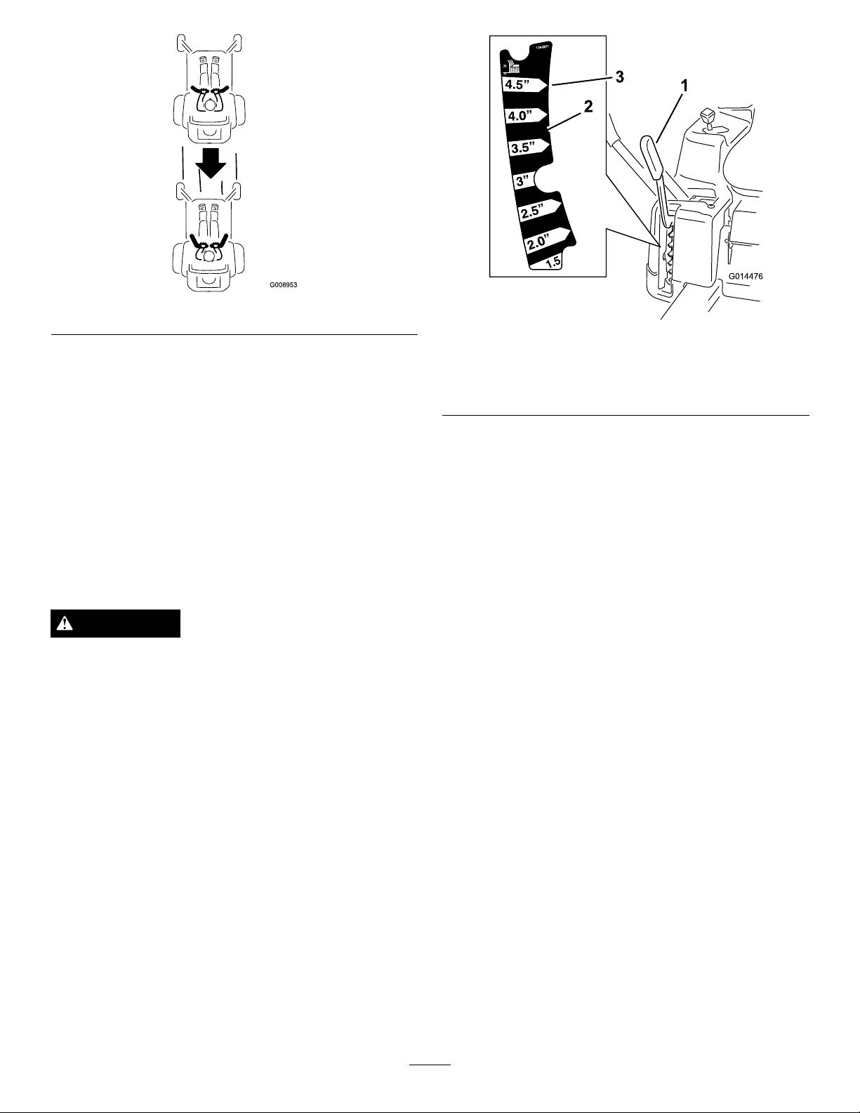
G014476
1
2
3
Togostraight,applyequalpressuretobothmotion
controllevers(Figure19).
Toturn,releasethepressureonthemotioncontrol
levertowardthedirectionyouwanttoturn.
Tostop,pushthemotioncontrolleverstoneutral.
Figure20
1.Height-of-cutlever3.115mm(4.5inch),
Transportposition
2.Height-of-cutpositions
1.Pullupandinwardonthelevertomoveittothe
desiredcuttingposition.
StoppingtheMachine
Tostopthemachine,movethemotioncontrolleversto
neutralandoutwardtotheparkposition,disengagetheblade
controlswitch,ensurethethrottleisinthefastposition,and
turntheignitionkeytooff.Remembertoremovethekey
fromtheignitionswitch.
WARNING
Childrenorbystandersmaybeinjuredifthey
moveorattempttooperatethemowerwhileitis
unattended.
Alwaysremovetheignitionkeyandmovethe
motioncontrolleversoutwardtotheparkposition
whenleavingthemachineunattended,evenifjust
forafewminutes.
AdjustingtheHeightofCut
Height-of-cutiscontrolledbytheleverlocatedtotherightof
theoperatingposition(Figure20).
2.Onceatthedesiredcuttingposition,slowlylowerthe
leveruntilitengagestheposition.
Thetransportpositionisthehighestheight-of-cutpositionor
cuttingheight115mm[4.5inch](Figure20).
AdjustingtheAnti-Scalp Rollers
Wheneveryouchangetheheight-of-cut,itisrecommended
toadjusttheheightoftheanti-scalprollers.
Note:Adjusttheanti-scalprollerssotherollersdonottouch
thegroundinnormal,atmowingareas.
1.Disengagethebladecontrolswitch(PTO),movethe
motioncontrolleverstotheneutrallockpositionand
settheparkingbrake.
2.Stoptheengine,removethekey ,andwaitforallmoving
partstostopbeforeleavingtheoperatingposition.
3.Adjusttheanti-scalprollerstooneofthefollowing
positions:
•Upperhole—usethispositionwiththemowerdeck
inthe63mm(2-1/2inch)andbelowheight-of-cut
positions(
Figure21).
•Lowerhole—usethispositionwiththemower
deckinthe76mm(3inch)andaboveheight-of-cut
positions(
19
Figure21).
Page 20

g019929
1
2
3
4
5
Figure21
G014477
1
4
1
2
G014970
3
2.Movethecontrollevertothenextsetofholes.Secure
theleverwiththe2bolts(Figure23).
1.Anti-scalproller4.Upperhole—themower
2.Lowerhole—themower
deckinthe76mm(3inch)
andaboveheight-of-cut
positions
3.FlangeNut
deckinthe63mm
(2-1/2inch)andbelow
height-of-cutpositions
5.Bolt
PositioningtheSeat
1.Raisetheseatandloosentheadjustmentboltsjust
enoughthatseatcanmove(Figure22).
Figure23
1.Controlarmshaft3.Slotted,upperhole
2.Controllever
4.Bolt
3.Repeattheadjustmentfortheoppositecontrollever.
AdjustingtheTilt
Themotioncontrolleverscanbetiltedforeoraftfor
maximumoperatorcomfort.
1.Loosentheupperboltholdingthecontrollevertothe
controlarmshaft.
2.Loosenthelowerboltjustenoughtopivotthecontrol
leverforeoraft(
Figure23).Tightenbothboltsto
securethecontrolinthenewposition.
3.Repeattheadjustmentfortheoppositecontrollever.
PushingtheMachinebyHand
Important:Alwayspushthemachinebyhand.Never
towthemachinebecausedamagemayoccur.
Figure22
1.Adjustmentbolt
2.Movetheseattothedesiredpositionandtightenthe
bolts.
AdjustingtheMotionControl Levers
AdjustingtheHeight
Themotioncontrolleverscanbeadjustedhigherorlowerfor
maximumoperatorcomfort.
1.Removethe2boltsholdingthecontrollevertothe
controlarmshaft(Figure23).
Thismachinehasanelectricbrakemechanismandtopush
themachinetheignitionkeyneedstobeintheRunposition.
Thebatteryneedstobechargedandfunctioningforthe
electricbraketobedisengage.
ToPushtheMachine
1.Parkthemachineonalevelsurfaceanddisengagethe
bladecontrolswitch.
2.Movethemotioncontrolleversoutwardtopark
position,stoptheengine,andwaitforallmovingparts
tostopbeforeleavingtheoperatingposition.
3.Locatethebypassleversontheframeonbothsidesof
theengine.
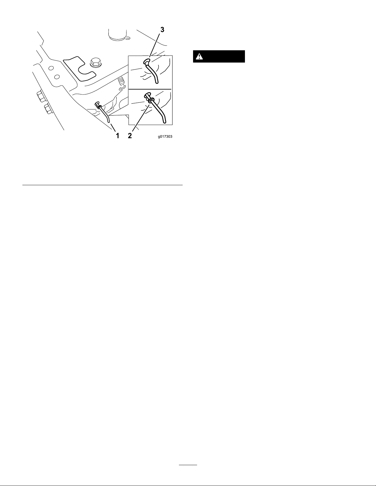
4.Movethebypassleversforwardthroughthekeyhole
anddowntolocktheminplaceasshowninFigure24.
Ensurethisisdoneforeachlever.
5.Movethemotioncontrolleversinwardtotheneutral
positionandturntheignitionkeytotherunposition.
Donotstartthemachine.
20
Page 21
Themachineisnowabletobepushedbyhand.
g017303
1 2
3
Figure24
GrassDeector
Themowerhasahingedgrassdeectorthatdisperses
clippingstothesideanddowntowardtheturf.
DANGER
Withoutthegrassdeector,dischargecover,or
completegrasscatcherassemblymountedin
place,youandothersareexposedtobladecontact
andthrowndebris.Contactwithrotatingmower
blade(s)andthrowndebriswillcauseinjuryor
death.
•Neverremovethegrassdeectorfromthemower
becausethegrassdeectorroutesmaterialdown
towardtheturf.Ifthegrassdeectorisever
damaged,replaceitimmediately .
1.Bypassleverlocations
2.Leverpositionfor
operatingthemachine
6.Whennished,ensurethekeyhasbeenreturnedtothe
Stoppositiontoavoiddrainingthebatterycharge.
Ifthemachinefailstomovetheelectricbrakemaystillbe
engaged.Ifnecessarytheelectricbrakecanbereleased
manually.RefertotheReleasingtheElectricBrake(page31)
procedureinDriveMaintenance.
3.Leverpositionforpushing
themachine
ToOperatetheMachine
Movethebypassleversrearwardthroughthekeyholeand
downtolocktheminplaceasshown(Figure24).Ensurethis
isdoneforeachlever.
•Neverputyourhandsorfeetunderthemower.
•Nevertrytocleardischargeareaormower
bladesunlessyoumovethebladecontrolswitch
toOffandrotatetheignitionkeytoOff.Also
removethekeyandpullthewireoffthespark
plug(s).
OperatingTips
FastThrottleSetting
Forbestmowingandmaximumaircirculation,operatethe
engineattheFastposition.Airisrequiredtothoroughlycut
grassclippings,sodonotsettheheight-of-cutsolowasto
totallysurroundthemowerbyuncutgrass.Alwaystrytohave
onesideofthemowerfreefromuncutgrass,whichallowsair
tobedrawnintothemower.
UsingtheSmartSpeed™Control
System
TheSmartSpeed™ControlSystemlever,locatedbelowthe
operatingposition,givestheoperatorachoicetodrivethe
machineattwospeedranges,highandlow.Anoperator
canbenetfromthelowerspeedsettingwhenmaneuvering
themachineintightspacesoroperatingarounddelicate
landscapes.Thelowsettingcanalsobeusedtooperatethe
machineatahighthrottlesettingandbladespeedwhilestill
beingabletoreducegroundspeedtoincreasequalityofcut.
CuttingaLawnfortheFirstTime
Cutgrassslightlylongerthannormaltoensurethatthe
cuttingheightofthemowerdoesnotscalpanyuneven
ground.However,thecuttingheightusedinthepastis
generallythebestonetouse.Whencuttinggrasslongerthan
sixinchestall,youmaywanttocutthelawntwicetoensure
anacceptablequalityofcut.
21
Page 22

Cut1/3oftheGrassBlade
Itisbesttocutonlyabout1/3ofthegrassblade.Cutting
morethanthatisnotrecommendedunlessgrassissparse,or
itislatefallwhengrassgrowsmoreslowly.
MowingDirection
Alternatemowingdirectiontokeepthegrassstanding
straight.Thisalsohelpsdisperseclippingswhichenhances
decompositionandfertilization.
MowatCorrectIntervals
Normally,moweveryfourdays.Butremember,grassgrows
atdifferentratesatdifferenttimes.Sotomaintainthesame
cuttingheight,whichisagoodpractice,mowmoreoftenin
earlyspring.Asthegrassgrowthrateslowsinmidsummer,
mowlessfrequently .Ifyoucannotmowforanextended
period,rstmowatahighcuttingheight;thenmowagain
twodayslateratalowerheightsetting.
AvoidCuttingTooLow
Ifthecuttingwidthofthemoweriswiderthanthemower
youpreviouslyused,raisethecuttingheighttoensurethat
uneventurfisnotcuttooshort.
LongGrass
Ifthegrassiseverallowedtogrowslightlylongerthan
normal,orifitcontainsahighdegreeofmoisture,raisethe
cuttingheighthigherthanusualandcutthegrassatthis
setting.Thencutthegrassagainusingthelower,normal
setting.
WhenStopping
Ifthemachine'sforwardmotionmustbestoppedwhile
mowing,aclumpofgrassclippingsmaydropontoyour
lawn.Toavoidthis,moveontoapreviouslycutareawiththe
bladesengagedoryoucandisengagethemowerdeckwhile
movingforward.
KeeptheUndersideoftheMowerClean
Cleanclippingsanddirtfromtheundersideofthemower
aftereachuse.Ifgrassanddirtbuildupinsidethemower,
cuttingqualitywilleventuallybecomeunsatisfactory.
BladeMaintenance
Maintainasharpbladethroughoutthecuttingseasonbecause
asharpbladecutscleanlywithouttearingorshreddingthe
grassblades.Tearingandshreddingturnsgrassbrownat
theedges,whichslowsgrowthandincreasesthechanceof
disease.Checkthecutterbladesdailyforsharpness,andfor
anywearordamage.Filedownanynicksandsharpenthe
bladesasnecessary.Ifabladeisdamagedorworn,replaceit
immediatelywithagenuineTororeplacementblade.
22
Page 23

Maintenance
Note:Determinetheleftandrightsidesofthemachinefromthenormaloperatingposition.
RecommendedMaintenanceSchedule(s)
MaintenanceService
Interval
Aftertherst5hours
Beforeeachuseordaily
Aftereachuse
Every25hours
Every50hours
Every100hours
Beforestorage
MaintenanceProcedure
•Changetheengineoil.
•Checkthesafetyinterlocksystem.
•Cleanandchecktheaircleanerfoamelement.
•Cleantheengineairintakescreen.
•Checkthecuttingblades.
•Inspectthegrassdeectorfordamage
•Cleanthemowerhousing.
•Greasealllubricationpoints.
•Checktirepressure.
•Checkthebeltsforwear/cracks.
•Replacetheaircleanerpaperelement.
•Checkthesparkplug.
•Changetheengineoil.
•Changetheoillter .
•Replacethesparkplug.
•Replacethein-linefuellter
•Cleantheenginecoolingnsandshrouds.
•Chargethebatteryanddisconnectbatterycables.
•Performallmaintenanceprocedureslistedabovebeforestorage.
•Paintanychippedsurfaces.
Important:Refertoyourengineoperator'smanualforadditionalmaintenanceprocedures.
CAUTION
Ifyouleavethekeyintheignitionswitch,someonecouldaccidentlystarttheengineandseriouslyinjure
youorotherbystanders.
Removethekeyfromtheignitionanddisconnectthewirefromthesparkplugbeforeyoudoany
maintenance.Setthewireasidesothatitdoesnotaccidentallycontactthesparkplug.
Premaintenance
Lubrication
Procedures
GreasingtheBearings
RaisingtheSeat
Makesurethemotioncontrolleversarelockedinthepark
position.Lifttheseatforward.
Thefollowingcomponentscanbeaccessedbyraisingtheseat:
•Serialplate
•Servicedecal
•Seatadjustmentbolts
•Fuellter
•Batteryandbatterycables
ServiceInterval:Every25hours—Greasealllubrication
points.
GreaseType:No.2GeneralPurposeLithiumBaseGrease
1.Parkthemachineonalevelsurfaceanddisengagethe
bladecontrolswitch.
2.Movethemotioncontrolleversoutwardtothepark
position,stoptheengine,removethekey,andwaitfor
allmovingpartstostopbeforeleavingtheoperating
position.
23
Page 24
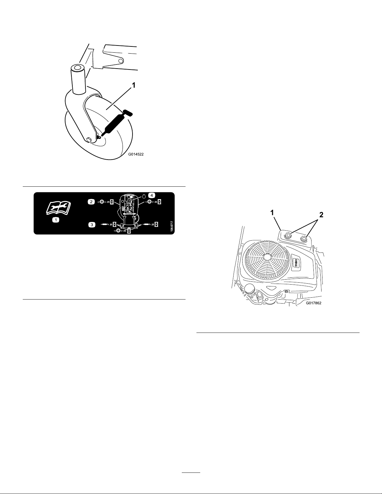
3.Cleanthegreasettings(Figure25andFigure26)with
1
G014522
G017862
arag.Makesuretoscrapeanypaintoffofthefront
ofthetting(s).
Figure25
1.Frontcastertire
EngineMaintenance
ServicingtheAirCleaner
ServiceInterval:Beforeeachuseordaily—Cleanandcheck
theaircleanerfoamelement.
Every50hours—Replacetheaircleanerpaper
element.
Note:Servicetheaircleanermorefrequentlyiftheoperating
conditionsareextremelydustyorsandy.
RemovingtheFoamandPaper
Elements
1.Disengagethebladecontrol(PTO).
2.Stoptheengine,waitforallmovingpartstostop,and
removethekeybeforeleavingtheoperatingposition.
3.Cleanaroundtheaircleanertopreventdirtfrom
gettingintotheengineandcausingdamage.
4.Removetheaircleanercoverbyunscrewingthe2
knobs(
Figure27).
Figure26
Locatedontheseatpanunderside
1.Readtheinstructions
beforeservicingor
performingmaintenance.
2.Checktirepressureevery
25operatinghours.
3.Greaseevery25operating
hours.
4.Engine
4.Connectagreaseguntoeachtting(Figure25and
Figure26).Pumpgreaseintothettingsuntilgrease
beginstooozeoutofthebearings.
5.Wipeupanyexcessgrease.
Figure27
1.Aircleanercover2.Knobs
5.Carefullyremovethefoamandpaperlterelements
fromtheaircleanerhousing(Figure28).
24
Page 25
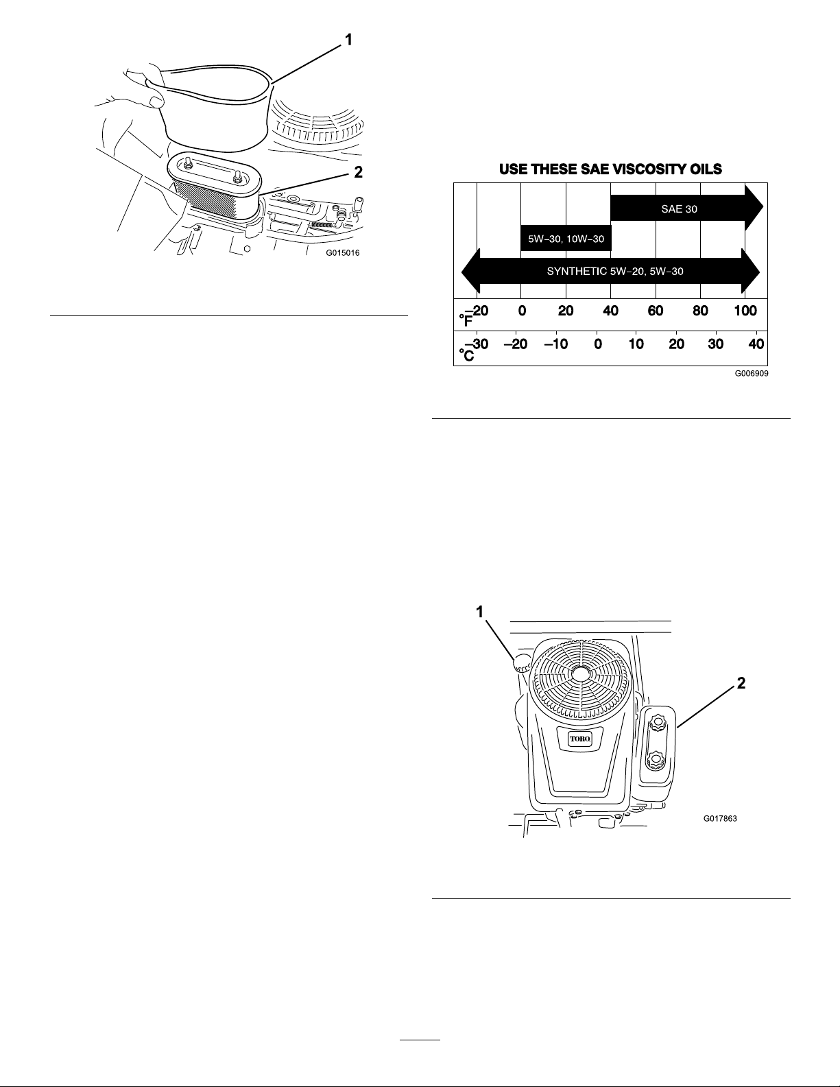
Figure28
G017863
2
1.Foamelement2.Paperelement
6.Separatethefoamandpaperelements.
ServicingtheEngineOil
OilType:Detergentoil(APIserviceSF,SG,SH,SJ,orhigher)
CrankcaseCapacity:1.0l(34ounces)whenyoudonotchange
thelter;1.05l(36ounces)whenyouchangethelter.
Viscosity:Seethetablebelow .
CleaningtheFoamandPaperElements
FoamElement:
1.Washthefoamelementinliquidsoapandwarmwater.
Whentheelementisclean,rinseitthoroughly .
2.Drytheelementbysqueezingitinacleancloth.Do
notoiltheelement.
Important:Replacethefoamelementifitistorn
orworn.
3.Installthefoamelementonacleanpaperelement.
PaperElement:
1.Tapthepaperelementonasolidatsurfaceandblow
itoutfromtheinsidewithcompressedairtoremove
dustanddirt.
2.Inspecttheelementfortears,anoilylm,anddamage
totherubberseal.
Important:Donotcleanthepaperelementwith
liquids,suchassolvents,gasoline,orkerosene.
Replacethepaperelementifitisdamagedor
cannotbecleanedthoroughly.
Figure29
CheckingtheOilLevel
1.Parkthemachineonalevelsurface.
2.Disengagethebladecontrol(PTO).
3.Stoptheengine,waitforallmovingpartstostop,and
removethekeybeforeleavingtheoperatingposition.
4.Cleanaroundtheoildipstick(Figure30)sothatdirt
cannotfallintothellholeanddamagetheengine.
3.Cleantheinsideoftheaircleanercoverofalldirt,dust,
anddebris.
InstallingtheFoamandPaperElements
Important:T opreventenginedamage,alwaysoperate
theenginewiththecompletefoamandpaperaircleaner
assemblyinstalled.
1.Installthefoamlterontothepaperlter(Figure28).
2.Installthefoamandpaperlterontotheaircleaner
housing.
3.Installtheaircleanercoverandtightenthetwoknobs
(Figure27).
Figure30
1.Oildipstick/llhole
5.Unscrewtheoildipstickandwipetheendclean.
6.Screwtheoildipstickfullyontothellhole.
7.Unscrewthedipstickagainandlookattheend.Ifthe
oillevelislow ,slowlypouronlyenoughoilintothell
holetoraisetheleveltotheFullmarkonthedipstick.
25
2.Aircleaner
Page 26

Important:Donotoverllthecrankcasewithoil
G017864
1
2
3
4
andruntheengine;enginedamagemayresult.
ChangingtheOil
ServiceInterval:Aftertherst5hours
Every100hours
1.Parkthemachinesothattherightsideisslightly
lowerthantheleftsidetoensurethattheoildrains
completely.
2.Disengagethebladecontrol(PTO).
3.Stoptheengine,waitforallmovingpartstostop,and
removethekeybeforeleavingtheoperatingposition.
4.Cleantheareaaroundthedrainvalveandonthe
machineframe.Locatetheoildrainhoseandslideit
overthedrainvalve(Figure31).
5.Placetheoppositeendoftheoildrainhoseoverthe
machineframe.
6.Placeapanunderneaththemachinedirectlybelowthe
drainhoseasshownin(
Figure31).
11.Installtheoilllcap/dipstick.
ChangingtheOilFilter
ServiceInterval:Every100hours
Note:Changetheoilltermorefrequentlywhenthe
operatingconditionsareextremelydustyorsandy.
1.Draintheoilfromtheengine;refertoChangingthe
Oil.
2.Removetheoldoillterandwipethelteradapter
Figure32)gasketsurface.
(
Figure32
Figure31
1.Oilllhole3.Oildrainhose
2.Drainvalve4.Pan
7.Turnthedrainvalve1/4counterclockwisetoopenand
allowtheoiltodrain.Removetheoilllcap/dipstick
(Figure31).
8.Whenoilhasdrainedcompletely,closetheoildrain
valve.Removetheoildrainhoseandwipeupany
excessoilontheframe.
Note:Disposeoftheusedoilatacertiedrecycling
center.
9.Changetheoillter;refertoChangingtheOilFilter.
10.Slowlypourapproximately80%ofthespecied
amountofoilintothellhole(
oillevel;refertoCheckingtheOilLevel.
Figure31).Checkthe
1.Oillter
2.Gasket
3.Applyathincoatofnewoiltotherubbergasketon
thenewoillter(Figure32).
4.Installthenewoilltertothelteradapter.
5.Turntheoillterclockwiseuntiltherubbergasket
contactsthelteradapter,thentightentheoillteran
additional1/2to3/4turn(
6.Slowlypourabout80%ofthespeciedamountofoil
intothellhole(Figure30).Checktheoillevel;refer
totheCheckingtheOilLevelprocedure.
3.Filteradapter
Figure32).
ServicingtheSparkPlug
ServiceInterval:Every50hours—Checkthesparkplug.
Every100hours—Replacethesparkplug.
Ensurethattheairgapbetweenthecenterandsideelectrodes
iscorrectbeforeinstallingthesparkplug.Useasparkplug
wrenchforremovingandinstallingthesparkpluganda
gappingtoolorfeelergaugetocheckandadjusttheairgap.
Installanewsparkplugifnecessary.
Type:ChampionRC12YC,Autolite3924,NGKBCPR6ES
orequivalent
AirGap:0.76mm(0.030inch)
RemovingtheSparkPlug
1.Disengagethebladecontrol(PTO).
2.Stoptheengine,waitforallmovingpartstostop,and
removethekeybeforeleavingtheoperatingposition.
26
Page 27

3.Disconnectthewirefromthesparkplug(Figure33).
G017865
1
Figure33
1.Spark-plugwire
4.Cleanaroundthesparkplugtopreventdirtfromfalling
intotheengineandpotentiallycausingdamage.
5.Removethesparkplugandmetalwasher.
InstallingtheSparkPlug
1.Installthesparkplugandmetalwasher.
Note:Ensurethattheairgapissetcorrectly.
2.Tightenthesparkplugto20N-m(15ft-lb).
3.Connectthewiretothesparkplug.
CheckingtheSparkPlug
1.Inspectthesparkplug(Figure34).
Note:Ifyouseelightbrownorgrayontheinsulator,
theengineisoperatingproperly.Ablackcoatingonthe
insulatorusuallymeansthattheaircleanerisdirty.
Figure34
1.Centerelectrodeinsulator3.Airgap(nottoscale)
2.Sideelectrode
Important:Donotcleanthesparkplug.Always
replacethesparkplugwhenithasablackcoating,
wornelectrodes,anoilylm,orcracks.
2.Checkthegapbetweenthecenterandsideelectrodes
(
Figure34).Bendthesideelectrodeifthegapisnot
correct.
27
Page 28

FuelSystem
G017861
1
2
3
4
5
Maintenance
DANGER
Incertainconditions,gasolineisextremely
ammableandhighlyexplosive.Areorexplosion
fromgasolinecanburnyouandothersandcan
damageproperty.
•Performanyfuelrelatedmaintenancewhenthe
engineiscold.Dothisoutdoorsinanopenarea.
Wipeupanygasolinethatspills.
•Neversmokewhendraininggasoline,andstay
awayfromanopenameorwhereasparkmay
ignitethegasolinefumes.
ReplacingtheIn-lineFuel Filter
ServiceInterval:Every100hours—Replacethein-linefuel
lter
5.Removethelterfromthefuellines.
6.Installanewlterwiththeowdirectionarrowcoming
fromthefueltankandpointingtotheengine.Move
thehoseclampsclosetothelter(Figure35)tosecure
itinplace.
Neverinstalladirtylterifitisremovedfromthefuelline.
1.Parkthemachineonalevelsurfaceanddisengagethe
bladecontrolswitch.
2.Movethemotioncontrolleversoutwardtothepark
position,stoptheengine,removethekey,andwaitfor
allmovingpartstostopbeforeleavingtheoperating
position.
3.Raisetheseatandlocatethefuelltersasshownin
Figure35.
Figure35
1.Fuellinetoengine4.Flowdirectionarrow
2.In-lineFuellter
3.Fuellinefromtank
4.Squeezetheendsofthehoseclampstogetherandslide
themawayfromthelter(Figure35).
5.Hoseclamp
28
Page 29

ElectricalSystem
G005072
1
2
3
4
5
6
7
Maintenance
WARNING
CALIFORNIA
Proposition65Warning
Batteryposts,terminals,andrelated
accessoriescontainleadandleadcompounds,
chemicalsknowntotheStateofCalifornia
tocausecancerandreproductiveharm.
Washhandsafterhandling.
ChargingtheBattery
RemovingtheBattery
WARNING
5.Slidetherubbercoverupthepositive(red)cable.
Disconnectthepositive(red)cablefromthebattery
post(Figure36).Retainallfasteners.
6.Removethebatteryhold-down(Figure36)andliftthe
batteryfromthebatterytray .
Batteryterminalsormetaltoolscouldshortagainst
metalmachinecomponentscausingsparks.Sparks
cancausethebatterygassestoexplode,resulting
inpersonalinjury.
•Whenremovingorinstallingthebattery,donot
allowthebatteryterminalstotouchanymetal
partsofthemachine.
•Donotallowmetaltoolstoshortbetween
thebatteryterminalsandmetalpartsofthe
machine.
1.Parkthemachineonalevelsurfaceanddisengagethe
bladecontrolswitch.
2.Movethemotioncontrolleversoutwardtothepark
position,stoptheengine,removethekey,andwaitfor
allmovingpartstostopbeforeleavingtheoperating
position.
3.Raisetheseattoaccessthebattery.
4.Disconnectthenegative(black)groundcablefromthe
batterypost(
WARNING
Incorrectbatterycableroutingcoulddamage
Figure36).Retainallfasteners.
themachineandcablescausingsparks.
Sparkscancausethebatterygassesto
explode,resultinginpersonalinjury.
•Alwaysdisconnectthenegative(black)
batterycablebeforedisconnectingthe
positive(red)cable.
•Alwaysconnectthepositive(red)battery
cablebeforeconnectingthenegative
(black)cable.
Figure36
1.Battery5.Negativebatterypost
2.Positivebatterypost6.Wingnut,washer,andbolt
3.Bolt,washer,andnut7.Batteryhold-down
4.Terminalboot
ChargingtheBattery
ServiceInterval:Beforestorage—Chargethebatteryand
disconnectbatterycables.
1.Removethebatteryfromthechassis;refertoRemoving
theBattery.
2.Chargethebatteryforaminimumof1hourat6to10
amps.Donotoverchargethebattery.
3.Whenthebatteryisfullycharged,unplugthecharger
fromtheelectricaloutlet,thendisconnectthecharger
leadsfromthebatteryposts(
Figure37).
29
Page 30

Figure37
30
25
30
25
G014540
2
1
1.Positivebatterypost
2.Negativebatterypost
3.Red(+)chargerlead
4.Black(-)chargerlead
Note:Donotrunthemachinewiththebattery
disconnected,electricaldamagemayoccur.
InstallingtheBattery
1.Positionthebatteryinthetray(Figure36).
2.Installthepositive(red)batterycabletothepositive(+)
batteryterminalusingthefastenersremovedpreviously .
3.Installthenegativebatterycabletothenegative(-)
batteryterminalusingthefastenersremovedpreviously .
4.Slidetheredterminalbootontothepositive(red)
batterypost.
5.Securethebatterywiththehold-down(
Figure36).
6.Lowertheseat.
ServicingtheFuses
Figure38
1.Main-30amp
2.Chargecircuit-25amp
4.Returnthecontrolpaneltoitsoriginalposition.Use
thescrewsremovedpreviouslytosecurethepanelto
themachine.
Theelectricalsystemisprotectedbyfuses.Itrequires
nomaintenance;however,ifafuseblows,checkthe
component/circuitforamalfunctionorshort.
Fuse:
•MainF1-30amp,blade-type
•ChargeCircuitF2-25amp,blade-type
1.Removethescrewssecuringthecontrolpaneltothe
machine.Retainallfasteners
2.Liftthecontrolpaneuptoaccessthemainwiring
harnessandfuseblock(
3.Toreplaceafuse,pulloutonthefusetoremoveit
(
Figure38).
Figure38).
30
Page 31

DriveSystem
G015000
1
Maintenance
CheckingtheTirePressure
ServiceInterval:Every25hours—Checktirepressure.
Maintaintheairpressureinthefrontandreartiresas
specied.Uneventirepressurecancauseunevencut.Check
thepressureatthevalvestem(Figure39).Checkthetires
whentheyarecoldtogetthemostaccuratepressurereading.
Refertothemaximumpressuresuggestedbythetire
manufactureronthesidewallofthecasterwheeltires.
Inatethereardrivewheeltiresto12psi.
2.Rotatetheshaftforwardtoreleasethebrake.
Figure39
1.Valvestem
ReleasingtheElectricBrake
Theelectricbrakecanbereleasedbymanuallyrotatingthe
linkarmsforward.Oncetheelectricbrakeisenergizedthe
brakewillreset.
Toreleasethebrake:
Figure40
1.Brakelinkarmontheelectricbrakecontrolmodule
1.Locatetheshaftontheelectricbrakewherethebrake
linkarmsareconnected.
31
Page 32

CoolingSystem
Maintenance
MowerMaintenance
ServicingtheCuttingBlades
CleaningtheEngineScreen
ServiceInterval:Beforeeachuseordaily—Cleantheengine
airintakescreen.
Toensurepropercooling,makesurethegrassscreen,cooling
ns,andotherexternalsurfacesoftheenginearekeptclean
atalltimes.
Useadrybrushtocleangrassandaccumulateddebrisfrom
theairintakescreenandaroundtheengine.
Important:T opreventcontaminatingthefuelsystem,
donotusewatertocleantheengine.
CleaningtheEngineCooling FinsandShrouds
ServiceInterval:Every100hours—Cleantheenginecooling
nsandshrouds.
1.Disengagethebladecontrolswitchandmovethe
controlleverstotheneutrallockedpositionandapply
theparkingbrake.
2.Stoptheengine,removethekey ,andwaitforallmoving
partstostopbeforeleavingtheoperatingposition.
3.Removetheairintakescreenandcoolingshrouds.
4.Cleanthedebrisandgrassfromtheengineparts.
5.Installtheairintakescreenandcoolingshrouds.
Maintainsharpbladesthroughoutthecuttingseasonbecause
sharpbladescutcleanlywithouttearingorshreddingthegrass
blades.Tearingandshreddingturnsgrassbrownattheedges,
whichslowsgrowthandincreasesthechanceofdisease.
Checkthecutterbladesdailyforsharpness,andforany
wearordamage.Filedownanynicksandsharpenthe
bladesasnecessary.Ifabladeisdamagedorworn,replace
itimmediatelywithagenuineTororeplacementblade.For
convenientsharpeningandreplacement,youmaywantto
keepextrabladesonhand.
WARNING
Awornordamagedbladecanbreak,andapiece
ofthebladecouldbethrownintotheoperator's
orbystander'sarea,resultinginseriouspersonal
injuryordeath.
•Inspectthebladeperiodicallyforwearor
damage.
•Replaceawornordamagedblade.
BeforeInspectingorServicingthe
Blades
Parkthemachineonalevelsurface,disengagetheblade
controlswitch,andmovethemotioncontrolleversoutward
totheparkposition.Stoptheengineandremovethekey .
InspectingtheBlades
ServiceInterval:Beforeeachuseordaily—Checkthe
cuttingblades.
1.Inspectthecuttingedges(Figure41).Iftheedges
arenotsharporhavenicks,removeandsharpenthe
blades;refertoSharpeningtheBlades.
2.Inspecttheblades,especiallythecurvedarea(Figure
41).Ifyounoticeanydamage,wear,oraslotforming
inthisarea(item3inFigure41),immediatelyinstall
anewblade.
32
Page 33

Figure41
G009679
1
2
3
G009680
1
2
3
G009681
1
2
3
1.Cuttingedge3.Wear/slotforming
2.Curvedarea
4.Damage
CheckingforBentBlades
Note:Themachinemustbeonalevelsurfaceforthe
followingprocedure.
1.Raisethemowerdecktothehighestheight-of-cut
position;alsoconsideredthe'transport'position.
2.Whilewearingthicklypaddedglovesorotheradequate
handprotectionslowlyrotatebladetobemeasured
intoapositionthatallowseffectivemeasurementof
thedistancebetweenthecuttingedgeandthelevel
surfacethemachineison.
3.Measurefromthetipofthebladetotheatsurface
here.
Figure43
1.Blade,inpositionformeasuring
2.Levelsurface
3.Measureddistancebetweenbladeandsurface(A)
4.Rotatethesameblade180degreessothattheopposing
cuttingedgeisnowinthesameposition.
Figure44
1.Blade,sidepreviouslymeasured
2.Measurementpositionusedpreviously
Figure42
1.Deck3.Blade
2.Spindlehousing
3.Opposingsideofbladebeingmovedintomeasurement
position
5.Measurefromthetipofthebladetotheatsurface
here.Thevarianceshouldbenomorethan1/8inch
(3mm).
33
Page 34

G009680
1
2
3
Figure46
Figure45
1.Opposingbladeedge,inpositionformeasuring
2.Levelsurface
3.Secondmeasureddistancebetweenbladeandsurface(B)
WARNING
Abladethatisbentordamagedcouldbreak
apartandcouldseriouslyinjureorkillyouor
bystanders.
•Alwaysreplacebentordamagedblade
withanewblade.
•Neverleorcreatesharpnotchesinthe
edgesorsurfacesofblade.
A.IfthedifferencebetweenAandBisgreater
than1/8inch(3mm)replacethebladewitha
newblade.RefertoRemovingtheBladesand
InstallingtheBlades.
Note:Ifabentbladeisreplacedwithanewone
andthedimensionobtainedcontinuestoexceed
1/8inch(3mm),thebladespindlecouldbebent.
ContactanAuthorizedToroDealerforservice.
1.Sailareaofblade
2.Blade
3.Curvedwasher
4.Bladebolt
5.Bladestiffener
SharpeningtheBlades
1.Usealetosharpenthecuttingedgeatbothendsof
theblade(
bladeretainsitsbalanceifthesameamountofmaterial
isremovedfrombothcuttingedges.
1.Sharpenatoriginalangle
2.Checkthebalanceofthebladebyputtingitonablade
balancer(Figure48).Ifthebladestaysinahorizontal
position,thebladeisbalancedandcanbeused.Ifthe
bladeisnotbalanced,lesomemetalofftheendof
thesailareaonly(Figure47).Repeatthisprocedure
untilthebladeisbalanced.
Figure47).Maintaintheoriginalangle.The
Figure47
B.Ifthevarianceiswithinconstraints,movetothe
nextblade..
Repeatthisprocedureoneachblade.
RemovingtheBlades
Thebladesmustbereplacedifasolidobjectishit,ifthe
bladeisoutofbalance,orthebladeisbent.T oensure
optimumperformanceandcontinuedsafetyconformance
ofthemachine,usegenuineT ororeplacementblades.
Replacementbladesmadebyothermanufacturersmayresult
innon-conformancewithsafetystandards.
Holdthebladeendusingaragorthickly-paddedglove.
Removethebladebolt,curvedwasher,bladestiffener(42inch
modelsonly),andbladefromthespindleshaft(
Figure46).
Figure48
1.Blade2.Balancer
InstallingtheBlades
1.Installthebladeontothespindleshaft(Figure46).
Important:Thecurvedpartoftheblademustbe
pointingupwardtowardtheinsideofthemowerto
ensurepropercutting.
2.Installthebladestiffener(42inchmodelsonly),the
curvedwasher(cuppedsidetowardtheblade)andthe
bladebolt(
3.Torquethebladeboltto35-65ft-lb(47-88N-m).
34
Figure46).
Page 35
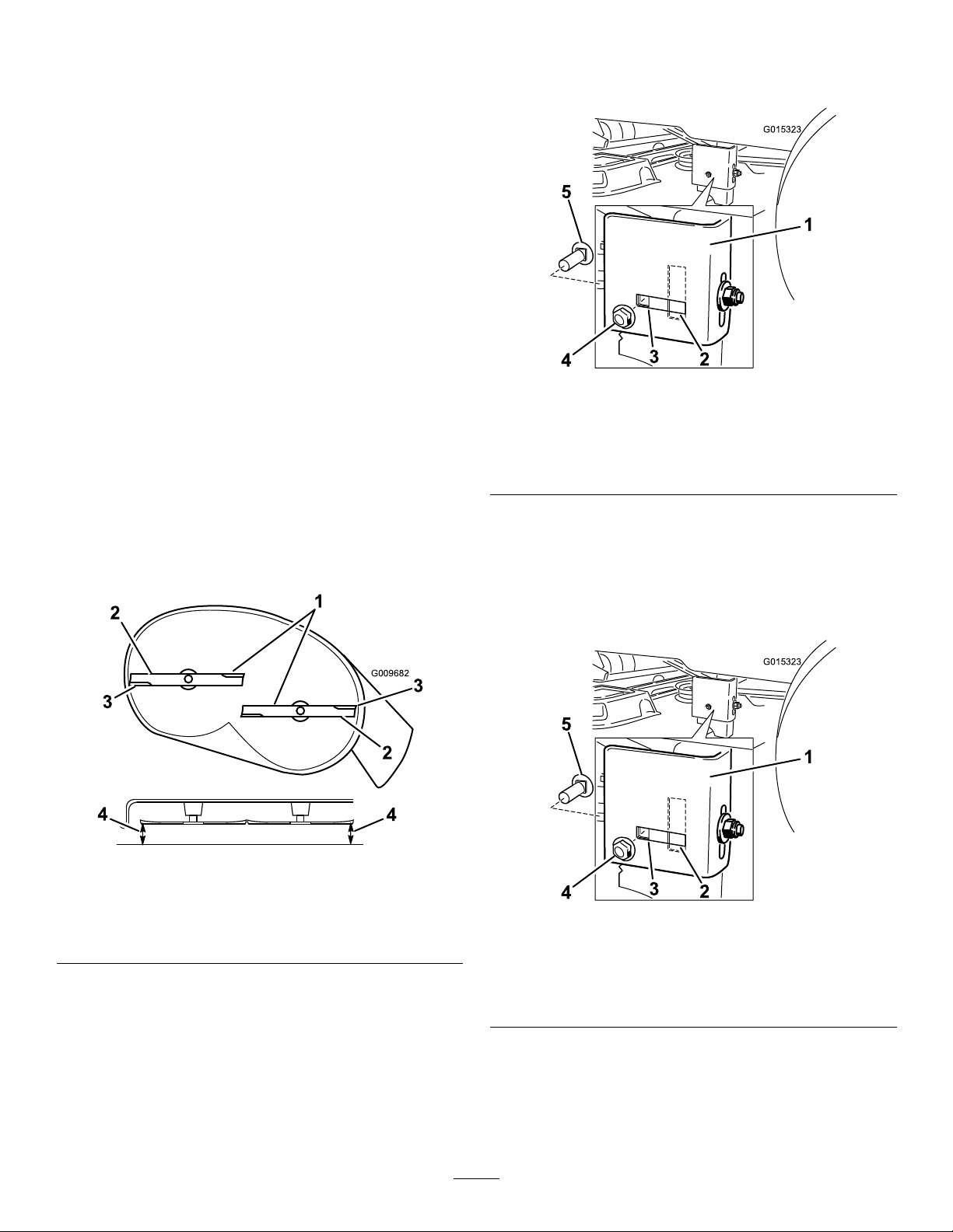
LevelingtheMowerDeck
G009682
1
2
2
3
3
4
4
G015323
1
2
3
4
5
G015323
1
2
3
4
5
Checktoensurethemowerdeckislevelanytimeyouinstall
themowerorwhenyouseeanunevencutonyourlawn.
Themowerdeckmustbecheckedforbentbladespriorto
leveling;anybentbladesmustberemovedandreplaced.Refer
totheCheckingforBentBladesprocedurebeforecontinuing.
Themowerdeckmustbeleveledside-to-siderstthenthe
fronttorearslopecanbeadjusted.
Requirements:
•Themachinemustbeonalevelsurface.
•Allfourtiremustbeproperlyinated.RefertoChecking
theTirePressureintheDriveSystemMaintenance
section.
7.Movetotheleftsideofthemachine.Checkiftheside
carriageboltisinthexedorslottedposition(Figure
50).
Side-to-SideLeveling
1.Parkthemachineonalevelsurfaceanddisengagethe
bladecontrolswitch.
2.Movethemotioncontrolleversoutwardtothepark
position,stoptheengine,removethekey,andwaitfor
allmovingpartstostopbeforeleavingtheoperating
position.
3.Settheheight-of-cutlevertomiddleposition.
4.Carefullyrotatethebladessothattheyareallsideto
side(Figure49).
Figure50
1.Hangerbracket
2.Slottedadjustment
position
3.Fixedposition
4.Sidelockingnut
5.Sidecarriagebolt
8.Ifthesidecarriageboltisinthexedposition,remove
thesidecarriageboltandsidelockingnutfromthe
xedpositionandinstallitintotheslottedadjustment
position(Figure51).
Iftheboltisintheslottedposition,thecarriagebolt
andsidelockingnutdonotneedtoberemoved.
Figure49
1.Bladessidetoside
2.Sailareaofblade4.Measurefromthetipofthe
surface(Figure49).Ifbothmeasurementsarenot
5.Measurebetweentheoutsidecuttingedgesandtheat
3.Outsidecuttingedges
bladetotheatsurface
here
1.Hangerbracket
2.Slottedadjustment
3.Fixedposition
Figure51
4.Sidelockingnut
5.Sidecarriagebolt
position
within3/16inch(5mm),anadjustmentisrequired;
6.Supporttheweightofmowerdeckbyplacingwood
blocksundertheedgesofthedeck.
continuewiththisprocedure.
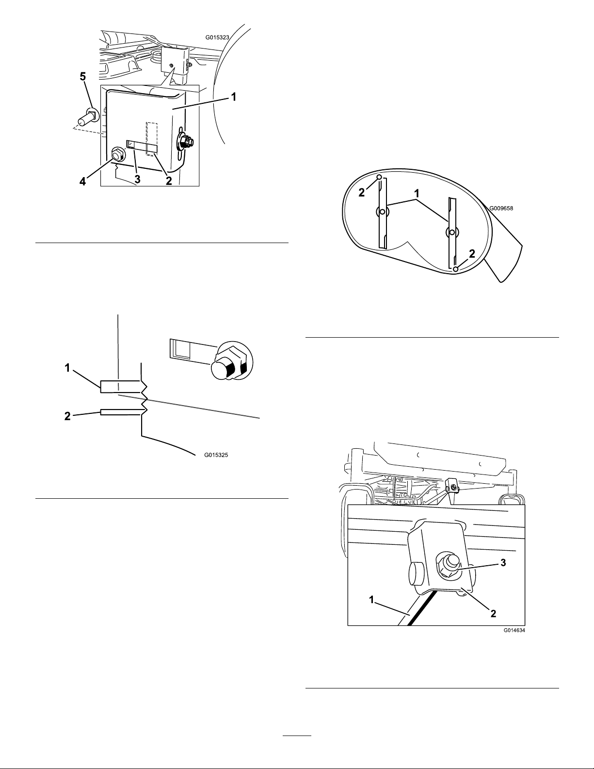
9.Loosentherearlockingnutonthehangerbracketjust
enoughtomovethebracket(Figure52).
Note:Avoidplacingthesupportsunderanyanti-scalp
rollersifpresentonthedeck.
35
Page 36
G015323
1
2
3
4
5
Figure52
G015325
1
2
G009658
1
2
2
G014634
1
2
3
2.Movethemotioncontrolleversoutwardtothepark
position,stoptheengine,removethekey,andwaitfor
allmovingpartstostopbeforeleavingtheoperating
position.
3.Settheheight-of-cutlevertomiddleposition.
Note:Checkandadjusttheside-to-sidebladelevelif
youhavenotcheckedthesetting;refertoSide-to-Side
Leveling.
4.Carefullyrotatethebladessotheyarefacingfrontto
rear(
Figure54).
1.Hangerbracket
2.Rearlockingnut4.Adjustmentnotches
3.Sidelockingnut
10.Usethenotchesontheweldedbrackettomeasure
theamountofadjustment.Eachnotchsurfaceis
equivalentto0.25inch,whileasinglesideis0.125
inch(Figure53).Adjusttheheightofthemowerdeck
tothedesiredheight.
Figure53
1.0.25inch2.0.125inch
Figure54
1.Bladesfronttorear
2.Measurefromthetipofthebladetotheatsurfacehere
5.Measurefromthetipofthefrontbladetotheat
surfaceandthetipoftherearbladetotheatsurface
(Figure54).Ifthefrontbladetipisnot1/16-5/16inch
(1.6-7.9mm)lowerthantherearbladetip,adjustthe
frontlocknut.
6.Toadjustthefront-to-rearbladeslope,rotatethe
adjustmentnutinthefrontofthemower(Figure55).
11.Stopthedeckattheadjustedpositionandtightenthe
rearlockingnutonthehangerbrackettoholdthenew
position(Figure52).Tightenthesidelockingnuton
thehangerbracket.
12.Continuelevelingthedeckbycheckingthefront-to-rear
bladeslope;refertoAdjustingtheFront-to-RearBlade
Slope.
AdjustingtheFront-to-RearBlade
Slope
Checkthefront-to-rearbladelevelanytimeyouinstallthe
mower.Ifthefrontofthemowerismorethan5/16inch
(7.9mm)lowerthantherearofthemower,adjusttheblade
levelusingthefollowinginstructions:
1.Parkthemachineonalevelsurfaceanddisengagethe
1.Adjustingrod3.Locknut
2.Adjustingblock
bladecontrolswitch.
36
Figure55
Page 37
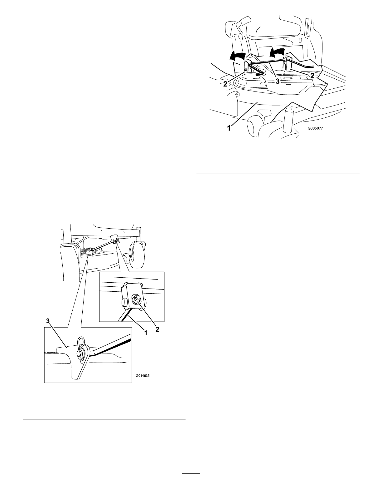
7.Toraisethefrontofthemower,tightentheadjustment
G014635
1
2
3
2
2
3
G005077
1
2
2
3
nut.T olowerthefrontofthemower,loosenthe
adjustmentnut.
8.Afteradjustment,checkthefront-to-rearslopeagain.
Continueadjustingthenutuntilthefrontbladetipis
1/16-5/16inch(1.6-7.9mm)lowerthantherearblade
tip(Figure54).
9.Whenthefront-to-rearbladeslopeiscorrectcheckthe
side-to-sidelevelofthemoweragain;refertoLeveling
theMowerfromSide-to-Side.
RemovingtheMower
1.Parkthemachineonalevelsurfaceanddisengagethe
bladecontrolswitch.
2.Movethemotioncontrolleversoutwardtothepark
position,stoptheengine,removethekey,andwaitfor
allmovingpartstostopbeforeleavingtheoperating
position.
1.Mowerdeck
2.Hangerbracket
Figure57
3.Rearliftrod
3.Lowertheheight-of-cutlevertothelowestposition.
4.Removethehairpincotterfromthefrontsupportrod
andremovetherodfromthedeckbracket(Figure
56).Carefullylowerthefrontofthemowerdeckto
theground.
6.Slidethemowerdeckrearwardtoremovethemower
beltfromtheenginepulley.
7.Slidethemowerdeckoutfromunderneaththe
machine.
Note:Retainallpartsforfutureinstallation.
MowerBeltMaintenance
InspectingtheBelts
ServiceInterval:Every25hours—Checkthebeltsfor
wear/cracks.
Checkthebeltsforcracks,frayededges,burnmarks,orany
otherdamage.Replacedamagedbelts.
ReplacingtheMowerBelt
Squealingwhenthebeltisrotating,bladesslippingwhen
cuttinggrass,frayedbeltedges,burnmarks,andcracksare
signsofawornmowerbelt.Replacethemowerbeltifanyof
theseconditionsareevident.
1.Parkthemachineonalevelsurfaceanddisengagethe
bladecontrolswitch.
2.Movethemotioncontrolleversoutwardtothepark
Figure56
1.Frontsupportrod3.Deckbracket
2.Lockingnut
5.Liftthemowerdeckandhangerbracketsclearof
therearliftrodandlowerthemowercarefullytothe
ground(Figure57).
37
position,stoptheengine,removethekey,andwaitfor
allmovingpartstostopbeforeleavingtheoperating
position.
3.Settheheight-of-cutatthelowestcuttingposition
[1-1/2inch(38mm)].
4.Usingaspringremovaltool,(Toropartno.92-5771),
removetheidlerspringfromthedeckhooktoremove
tensionontheidlerpulleyandrollthebeltoffofthe
pulleys(
Figure58).
Page 38
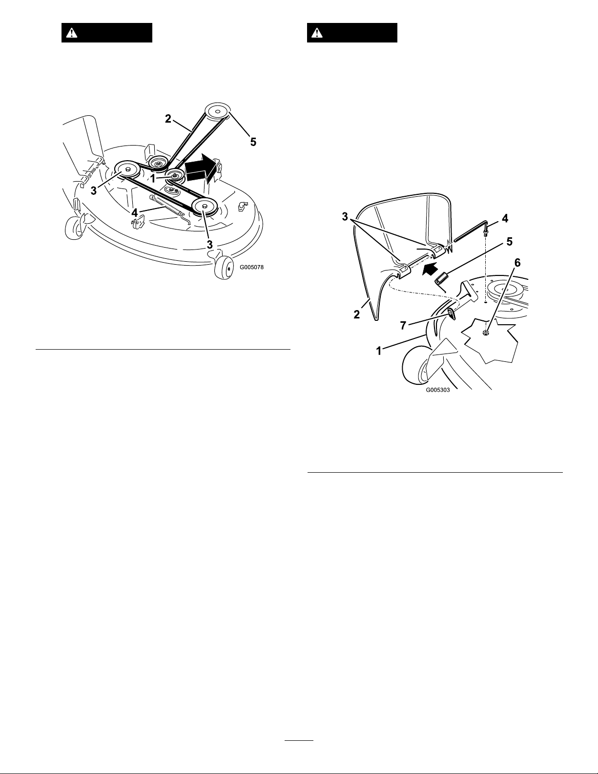
WARNING
G005078
1
2
3
3
4
5
1
2
3
3
4
5
G005303
1
2
3
4
5
6
7
WARNING
Thespringisundertensionwheninstalled
andcancausepersonalinjury.
Becarefulwhenremovingthebelt.
Figure58
1.Idlerpulley
2.Mowerbelt5.Enginepulley
3.Outsidepulley6.Springremovaltoo
4.Spring
Anuncovereddischargeopeningcouldallowthe
lawnmowertothrowobjectsintheoperator'sor
bystander'sdirectionandresultinseriousinjury.
Also,contactwiththebladecouldoccur.
Neveroperatethemachinewithoutgrassdeector,
dischargecoverorgrasscollectionsysteminplace.
Inspectthegrassdeectorfordamagebeforeeachuse.
Replaceanydamagedpartsbeforeuse.
1.LocateitemsshowninFigure59.
5.Routethenewbeltaroundtheenginepulleyand
mowerpulleys(
6.Usingaspringremovaltool,(Toropartno.92-5771),
installtheidlerspringoverthedeckhookandplacing
tensionontheidlerpulleyandmowerbelt(Figure58).
InstallingtheMower
1.Parkthemachineonalevelsurfaceanddisengagethe
bladecontrolswitch.
2.Movethemotioncontrolleversoutwardtothepark
position,stoptheengine,removethekey,andwaitfor
allmovingpartstostopbeforeleavingtheoperating
position.
3.Slidethemowerunderthemachine.
4.Lowertheheight-of-cutlevertothelowestposition.
5.Lifttherearofthemowerdeckandguidethehanger
bracketsovertherearliftrod(
6.Attachthefrontsupportrodtothemowerdeckwith
theclevispinandhairpincotter(
7.Installthemowerbeltontotheenginepulley;referto
ReplacingtheMowerBelt.
ReplacingtheGrassDeector
ServiceInterval:Beforeeachuseordaily—Inspectthegrass
Figure58).
deectorfordamage
Figure59
1.Mowerdeck
2.Grassdeector6.Nut(3/8inch)
3.Grassdeectorbracket7.Shortstand-off
4.Rod
2.Removethenut(3/8inch)fromtherodunderthe
mower(Figure59).
3.Slidetherodoutoftheshortstand-off,spring,and
grassdeector(Figure59).Removethedamagedor
worngrassdeector.
4.Replacethegrassdeector(Figure59).
5.Sliderod,straightend,throughthereargrassdeector
Figure57).
Figure56).
bracket.
6.Placethespringontherod,withendwiresdown,and
betweenthegrassdeectorbrackets.Sliderodthrough
secondgrassdeectorbracket(
7.Insertrodatfrontofgrassdeectorintoshort
stand-offondeck.Securerearendofrodintothe
mowerwithanut(3/8inch)(
Important:Thegrassdeectormustbespring
loadedinthedownposition.Liftthedeectorup
totestthatitsnapstothefulldownposition.
5.Spring
Figure59).
Figure59).
38
Page 39

Cleaning
G020098
2
4
1
2
3
4
WashingtheUndersideofthe Mower
ServiceInterval:Aftereachuse—Cleanthemowerhousing.
Washtheundersideofthemoweraftereachusetoprevent
grassbuildupforimprovedmulchactionandclipping
dispersal.
1.Parkthemachineonalevelsurfaceanddisengagethe
bladecontrolswitch.
2.Movethemotioncontrolleversoutwardtothepark
position,stoptheengine,removethekey,andwaitfor
allmovingpartstostopbeforeleavingtheoperating
position.
3.Attachthehosecouplingtotheendofthemower
washouttting,andturnthewateronhigh(Figure60).
Note:Spreadpetroleumjellyonthewashouttting
O-ringtomakethecouplingslideoneasierandprotect
theO-ring.
WARNING
Abrokenormissingwashoutttingcould
exposeyouandotherstothrownobjectsor
bladecontact.Contactwithbladeorthrown
debriscancauseinjuryordeath.
•Replacebrokenormissingwashouttting
immediately,beforeusingmoweragain.
•Neverputyourhandsorfeetunderthe
mowerorthroughopeningsinthemower.
Figure60
1.Washouttting3.O-ring
2.Hose
4.Lowerthemowertothelowestheight-of-cut.
5.Sitontheseatandstarttheengine.Engagetheblade
controlswitchandletthemowerrunforonetothree
minutes.
6.Disengagethebladecontrolswitch,stoptheengine,
andremovetheignitionkey.Waitforallmovingparts
tostop.
7.Turnthewateroffandremovethecouplingfromthe
washouttting.
Note:Ifthemowerisnotcleanafteronewashing,let
itsoakfor30minutes.Thenrepeattheprocedureof
washingtheundersideofthemower.
8.Runthemoweragainforonetothreeminutesto
removeexcesswater.
4.Coupling
39
Page 40

Storage
CleaningandStorage
1.Disengagethebladecontrolswitch,movethemotion
controlsoutwardtotheparkposition,stoptheengine,
andremovethekey.
2.Removegrassclippings,dirt,andgrimefromthe
externalpartsoftheentiremachine,especiallythe
engine.Cleandirtandchafffromtheoutsideofthe
enginecylinderheadnsandblowerhousing.
Important:Y oucanwashthemachinewithmild
detergentandwater.Donotpressurewashthe
machine.Avoidexcessiveuseofwater,especially
nearthecontrolpanel,engine,hydraulicpumps,
andmotors.
3.Servicetheaircleaner;refertoServicingtheAir
CleanerintheEngineMaintenancesection.
4.Greaseandoilthemachine;refertotheLubrication
section.
5.Changethecrankcaseoilandlter;refertoServicing
theEngineOilintheEngineMaintenancesection.
section.Withthesparkplug(s)removedfromthe
engine,pourtwotablespoonsofengineoilintothe
sparkplughole.Usethestartertocranktheengineand
distributetheoilinsidethecylinder.Installthespark
plug(s).Donotinstallthewireonthesparkplug(s).
12.Cleananydirtandchafffromthetopofthemower.
13.Scrapeanyheavybuildupofgrassanddirtfromthe
undersideofthemower,thenwashthemowerwith
agardenhose.
14.Checktheconditionofthedriveandmowerbelts.
15.Checkandtightenallbolts,nuts,andscrews.Repairor
replaceanypartthatiswornordamaged.
16.Paintallscratchedorbaremetalsurfaces.Paintis
availablefromyourAuthorizedServiceDealer.
17.Storethemachineinaclean,drygarageorstoragearea.
Removethekeyfromtheignitionswitchandkeepit
inamemorableplace.Coverthemachinetoprotect
itandkeepitclean.
6.Checkthetirepressure;refertoCheckingtheTire
PressureintheDriveSystemMaintenancesection.
7.Chargethebattery;refertoServicingtheBatteryinthe
ElectricalSystemMaintenancesection.
8.Checktheconditionoftheblades;refertoServicing
theCuttingBladesintheMowerMaintenancesection.
9.Preparethemachineforstoragewhennon-useoccurs
over30days.Preparethemachineforstorageas
follows.
10.Addapetroleumbasedstabilizer/conditionertothe
fuelinthetank.Followthemixinginstructionsfrom
thestabilizermanufacturer.Donotuseanalcohol
basedstabilizer(ethanolormethanol).
Note:Afuelstabilizer/conditionerismosteffective
whenmixedwithfreshgasolineandusedatalltimes.
Runtheenginetodistributetheconditionedfuel
throughthefuelsystem(5minutes).
Stoptheengine,allowittocool,anddrainthefueltank.
Restarttheengineandrunituntilitstops.
Choketheengine.Startandruntheengineuntilitwill
notstart.
Disposeoffuelproperly .Recyclepursuanttolocal
codes.
Important:Donotstorestabilizer/conditioned
gasolineover90days.
11.Removethesparkplug(s)andcheckitscondition;refer
toServicingtheSparkPlugintheEngineMaintenance
40
Page 41

Troubleshooting
Problem
Theengineoverheats.
Thestarterdoesnotcrank
Theenginewillnotstart,startshard,or
failstokeeprunning.
PossibleCauseCorrectiveAction
1.Theengineloadisexcessive.1.Reducegroundspeed.
2.Theoillevelinthecrankcaseislow .2.Addoiltothecrankcase.
3.Thecoolingnsandairpassages
undertheengineblowerhousingare
plugged.
4.Theaircleanerisdirty.
5.Dirt,water,orstalefuelisinfuel
system.
1.Thebladecontrolswitchisengaged.1.Movethebladecontrolswitchto
2.Themotioncontrolleversarenotinthe
parkposition.
3.Thebatteryisdead.
4.Theelectricalconnectionsarecorroded
orloose.
5.Afuseisblown.5.Replacethefuse.
6.Arelayorswitchisdamaged.
1.Thefueltankisempty.1.Fillthefueltank.
2.Thechokeisnoton.
3.Theaircleanerisdirty.
4.Thesparkplugwire(s)islooseor
disconnected.
5.Thesparkplug(s)ispitted,fouled,or
thegapisincorrect.
6.Thereisdirtinfuellter.6.Replacethefuellter.
7.Dirt,water,orstalefuelisinfuel
system.
8.Thereisincorrectfuelinthefueltank.8.Drainthetankandreplacethefuelwith
9.Theoillevelinthecrankcaseislow .9.Addoiltothecrankcase.
3.Removetheobstructionfromthe
coolingnsandairpassages.
4.Cleanorreplacetheaircleaner
element.
5.ContactanAuthorizedServiceDealer
Disengaged.
2.Movethemotioncontrolleversoutward
totheparkposition.
3.Chargethebattery .
4.Checktheelectricalconnectionsfor
goodcontact.
6.ContactanAuthorizedServiceDealer.
2.MovethechokelevertoOn.
3.Cleanorreplacetheaircleaner
element.
4.Installthewire(s)onthesparkplug.
5.Installanew,correctlygappedspark
plug(s).
7.ContactanAuthorizedServiceDealer.
thepropertype.
Theenginelosespower.
Themachinedoesnotdrive.
1.Theengineloadisexcessive.1.Reducegroundspeed.
2.Theaircleanerisdirty.
3.Theoillevelinthecrankcaseislow .3.Addoiltothecrankcase.
4.Thecoolingnsandairpassages
undertheengineblowerhousingare
plugged.
5.Thesparkplug(s)ispitted,fouled,or
thegapisincorrect.
6.Thefueltankventisblocked.6.ContactanAuthorizedServiceDealer.
7.Thereisdirtinthefuellter.7.Replacethefuellter.
8.Dirt,water,orstalefuelisinthefuel
system.
9.Thereisincorrectfuelinthefueltank.9.Drainthetankandreplacethefuelwith
1.Thebypassvalvesareopen.
2.Thetractionbeltsareworn,loose,or
broken.
3.Thetractionbeltsareoffofthepulleys.3.ContactanAuthorizedServiceDealer.
4.Thetransmissionhasfailed.4.ContactanAuthorizedServiceDealer.
2.Cleantheaircleanerelement.
4.Removetheobstructionfromthe
coolingnsandairpassages.
5.Installanew,correctlygappedspark
plug(s).
8.ContactanAuthorizedServiceDealer.
thepropertype.
1.Closethetowvalves.
2.ContactanAuthorizedServiceDealer.
41
Page 42

Problem
PossibleCauseCorrectiveAction
Thereisabnormalvibration.
Unevencuttingheight.
Thebladesdonotrotate.
1.Theenginemountingboltsareloose.1.Tightentheenginemountingbolts.
2.Theenginepulley,idlerpulley,orblade
pulleyisloose.
3.Theenginepulleyisdamaged.
4.Thecuttingblade(s)is/arebentor
unbalanced.
5.Ablademountingboltisloose.5.Tightentheblademountingbolt.
6.Abladespindleisbent.
1.Theblade(s)isnotsharp.1.Sharpentheblade(s).
2.Acuttingblade(s)is/arebent.2.Installanewcuttingblade(s).
3.Themowerisnotlevel.
4.Ananti-scalpwheelisnotsetcorrectly.4.Adjusttheanti-scalpwheelheight.
5.Theundersideofthemowerisdirty.5.Cleantheundersideofthemower.
6.Thetirepressureisincorrect.6.Adjustthetirepressure.
7.Abladespindleisbent.
1.Thedrivebeltisworn,looseorbroken.1.Installanewdrivebelt.
2.Thedrivebeltisoffofthepulley .
3.ThePowerT ake-Off(PTO)switchor
PTOclutchisfaulty.
4.Themowerbeltisworn,loose,or
broken.
2.Tightentheappropriatepulley .
3.ContactanAuthorizedServiceDealer.
4.Installanewcuttingblade(s).
6.ContactanAuthorizedServiceDealer.
3.Levelthemowerfromside-to-sideand
front-to-rear.
7.ContactanAuthorizedServiceDealer.
2.Installthedrivebeltandcheckthe
adjustingshaftsandbeltguidesforthe
correctposition.
3.ContactanAuthorizedServiceDealer.
4.Installanewmowerbelt.
42
Page 43

Schematics
G014644
ElectricalDiagram(Rev.A)
43
Page 44

TheToroTotalCoverageWarranty
LimitedWarranty(seewarrantyperiodsbelow)
TimeCutter
and
TITAN
Mowers
ConditionsandProductsCovered
TheT oroCompanyanditsafliate,T oroWarrantyCompany,pursuantto
anagreementbetweenthem,jointlypromisetotheoriginalpurchaser
torepairtheT oroProductslistedbelowifdefectiveinmaterialsor
workmanship.
Thefollowingtimeperiodsapplyfromthedateofpurchasebytheoriginal
owner:
ProductsWarrantyPeriod
TimeCutterandMXMowers
•Engines
1
Residentialuse
—ResidentialuseKawasaki–3years
2
–3years
Kohler–3years
Toro–3years
TimeCutterandMXMowersCommercialuse30days
•Engines
1
—Commercialuse
Kawasaki–3years
Kohler–90days
Toro–90days
TITANMowers–Residentialor
Commercialuse
•Engines
1
—Residentialor
Commercialuse
•Frame
TITANMX5400andMX600Mowers
–ResidentialorCommercialuse
•Engines
1
—Residentialor
Commercialuse
•Frame
3yearsor300hours
Kawasaki–3years
Lifetime(originalowneronly)
4yearsor400hours
Kawasaki–3years
Lifetime(originalowneronly)
3
4
3
4
AllMowers
•Attachments1year
•Battery90daysPartsandLabor
1yearPartsonly
•BeltsandTires90days
1
SomeenginesusedonT oroProductsarewarrantedbytheenginemanufacturer .
2
Residentialusemeansuseoftheproductonthesamelotasyourhome.Useatmorethanone
locationisconsideredcommercialuseandthecommercialusewarrantywouldapply .
3
Whicheveroccursrst.
4
LifetimeFrameW arranty-Ifthemainframe,consistingofthepartsweldedtogethertoformthe
tractorstructurethatothercomponentssuchastheenginearesecuredto,cracksorbreaksin
normaluse,itwillberepairedorreplaced,atT oro'soption,underwarrantyatnocostforparts
andlabor .Framefailureduetomisuseorabuseandfailureorrepairrequiredduetorustor
corrosionarenotcovered.
Warrantymaybedeniedifthehourmeterisdisconnected,altered,or
showssignsofbeingtamperedwith.
OwnerResponsibilities
YoumustmaintainyourT oroProductbyfollowingthemaintenance
proceduresdescribedintheOperator'sManual.Suchroutine
maintenance,whetherperformedbyadealerorbyyou,isatyourexpense.
InstructionsforObtainingWarrantyService
IfyouthinkthatyourT oroProductcontainsadefectinmaterialsor
workmanship,followthisprocedure:
1.ContactanyAuthorizedT oroServiceDealertoarrangeservice
attheirdealership.T olocateadealerconvenienttoyou,referto
theYellowPagesofyourtelephonedirectory(lookunder“Lawn
Mowers”)oraccessourwebsiteatwww .Toro.com.Y oumayalso
callthenumberslistedinitem#3tousethe24-hourT oroDealer
locatorsystem.
2.Bringtheproductandyourproofofpurchase(salesreceipt)tothe
ServiceDealer.Thedealerwilldiagnosetheproblemanddetermine
ifitiscoveredunderwarranty .
3.IfforanyreasonyouaredissatisedwiththeServiceDealer’s
analysisorwiththeassistanceprovided,contactusat:
CustomerCareDepartment,RLCDivision
ToroWarrantyCompany
811 1LyndaleAvenueSouth
Bloomington,MN55420-1 196
Tollfreeat866-216-6029(U.S.customers)
Tollfreeat866-216-6030(Canadiancustomers)
ItemsandConditionsNotCovered
Thereisnootherexpresswarrantyexceptforspecialemissionsystem
coverageandenginewarrantycoverageonsomeproducts.Thisexpress
warrantydoesnotcoverthefollowing:
•Costofregularmaintenanceserviceorparts,suchaslters,fuel,
lubricants,oilchanges,sparkplugs,airltersbladesharpening
orwornblades,cable/linkageadjustments,orbrakeandclutch
adjustments
•Componentsfailingduetonormalwear
•Anyproductorpartwhichhasbeenalteredormisusedorneglected
andrequiresreplacementorrepairduetoaccidentsorlackofproper
maintenance
•Pickupanddeliverycharges
•RepairsorattemptedrepairsbyanyoneotherthananAuthorized
ToroServiceDealer
•Repairsnecessaryduetofailuretofollowrecommendedfuel
procedure(consultOperator'sManualformoredetails)
–Removingcontaminantsfromthefuelsystemisnotcovered
–Useofoldfuel(morethanonemonthold)orfuelwhichcontains
morethan10%ethanolormorethat15%MTBE
–Failuretodrainthefuelsystempriortoanyperiodofnon-use
overonemonth
GeneralConditions
Allrepairscoveredbythesewarrantiesmustbeperformedbyan
AuthorizedT oroServiceDealerusingToroapprovedreplacementparts.
NeitherTheToroCompanynorToroWarrantyCompanyisliablefor
indirect,incidentalorconsequentialdamagesinconnectionwiththe
useoftheToroProductscoveredbythiswarranty ,includingany
costorexpenseofprovidingsubstituteequipmentorserviceduring
reasonableperiodsofmalfunctionornon-usependingcompletion
ofrepairsunderthiswarranty.
Allimpliedwarrantiesofmerchantability(thattheproductistfor
ordinaryuse)andtnessforuse(thattheproductistforaparticular
purpose)arelimitedtothedurationoftheexpresswarranty.
Somestatesdonotallowexclusionsofincidentalorconsequential
damages,orlimitationsonhowlonganimpliedwarrantylasts,so
theaboveexclusionsandlimitationsmaynotapplytoyou.
Thiswarrantygivesyouspeciclegalrights,andyoumayalsohaveother
rightswhichvaryfromstatetostate.
CountriesOtherthantheUnitedStatesorCanada
CustomerswhohavepurchasedT oroproductsoutsidetheUnitedStatesorCanadashouldcontacttheirToroDistributor(Dealer)toobtainguarantee
policiesforyourcountry,province,orstate.IfforanyreasonyouaredissatisedwithyourDistributor'sserviceorhavedifcultyobtainingguarantee
information,contacttheT oroimporter.Ifallotherremediesfail,youmaycontactusatT oroWarrantyCompany .
AustralianConsumerLaw:AustraliancustomerswillnddetailsrelatingtotheAustralianConsumerLaweitherinsidetheboxoratyourlocalToro
Dealer.
374-0258RevE
 Loading...