

Page 1
FormNo.3426-322RevA
SandPro
ModelNo.08706—SerialNo.403300001andUp
®
2040ZTractionUnit
Registeratwww.T oro.com.
OriginalInstructions(EN)
*3426-322*A
Page 2
ThisproductcomplieswithallrelevantEuropean
directives;fordetails,pleaseseetheseparateproduct
specicDeclarationofConformity(DOC)sheet.
ItisaviolationofCaliforniaPublicResourceCode
Section4442or4443touseoroperatetheengineon
anyforest-covered,brush-covered,orgrass-covered
landunlesstheengineisequippedwithaspark
arrester,asdenedinSection4442,maintainedin
effectiveworkingorderortheengineisconstructed,
equipped,andmaintainedforthepreventionofre.
Becauseinsomeareastherearelocal,state,or
federalregulationsrequiringthatasparkarresterbe
usedontheengineofthismachine,asparkarresteris
availableasanoption.Ifyourequireasparkarrester,
contactyourAuthorizedToroServiceDealer.
Theenclosedengineowner'smanualissupplied
forinformationregardingtheUSEnvironmental
ProtectionAgency(EPA)andtheCaliforniaEmission
ControlRegulationofemissionsystems,maintenance,
andwarranty.Replacementsmaybeorderedthrough
theenginemanufacturer.
Introduction
Thismachineisaride-onpieceofutilityequipment
intendedtobeusedbyprofessional,hiredoperators
incommercialapplications.Itisprimarilydesigned
forconditioningsandtrapsonwell-maintainedgolf
coursesandcommercialgrounds.
Readthisinformationcarefullytolearnhowtooperate
andmaintainyourproductproperlyandtoavoid
injuryandproductdamage.Youareresponsiblefor
operatingtheproductproperlyandsafely .
Visitwww.Exmark.comforproductsafetyand
operationtrainingmaterials,accessoryinformation,
helpndingadealer,ortoregisteryourproduct.
Wheneveryouneedservice,genuineToroparts,or
additionalinformation,contactanAuthorizedService
DealerorToroCustomerServiceandhavethemodel
andserialnumbersofyourproductready.Figure1
identiesthelocationofthemodelandserialnumbers
ontheproduct.Writethenumbersinthespace
provided.
WARNING
CALIFORNIA
Proposition65Warning
Theengineexhaustfromthisproduct
containschemicalsknowntotheStateof
Californiatocausecancer,birthdefects,
orotherreproductiveharm.
Batteryposts,terminals,andrelated
accessoriescontainleadandlead
compounds,chemicalsknownto
theStateofCaliforniatocause
cancerandreproductiveharm.Wash
handsafterhandling.
Useofthisproductmaycauseexposure
tochemicalsknowntotheStateof
Californiatocausecancer,birthdefects,
orotherreproductiveharm.
Important:Withyourmobiledevice,youcan
scantheQRcode(ifequipped)ontheserial
numberplatetoaccesswarranty ,parts,andother
productinformation.
©2018—TheToro®Company
8111LyndaleAvenueSouth
Bloomington,MN55420
1.Modelandserialnumberlocation
2
g234875
Figure1
Contactusatwww.Toro.com.
PrintedintheUSA
AllRightsReserved
Page 3

ModelNo.
SerialNo.
Thismanualidentiespotentialhazardsandhas
safetymessagesidentiedbythesafety-alertsymbol
(Figure2),whichsignalsahazardthatmaycause
seriousinjuryordeathifyoudonotfollowthe
recommendedprecautions.
Figure2
Safety-alertsymbol
Thismanualuses2wordstohighlightinformation.
Importantcallsattentiontospecialmechanical
informationandNoteemphasizesgeneralinformation
worthyofspecialattention.
Contents
Safety.......................................................................4
GeneralSafety...................................................4
SafetyandInstructionalDecals..........................5
Setup......................................................................10
1RemovingtheShippingBoard.........................11
2InstallinganAttachment..................................11
3InstallingtheFrontWeights.............................11
4ConnectingtheBattery..................................12
5ApplyingtheCEServiceDecal(CE
Only).............................................................12
6InstallingtheRollBar.....................................13
g000502
ProductOverview...................................................14
Controls...........................................................14
Specications..................................................16
Attachments/Accessories.................................16
BeforeOperation.................................................16
BeforeOperationSafety...................................16
BreakingintheMachine...................................17
InstallingandRemovingtheWeights................17
CheckingtheLeveloftheEngineOil.................17
FillingtheFuelTank..........................................19
CheckingtheLeveloftheHydraulic
Fluid..............................................................19
CheckingtheTirePressure...............................20
TorquingtheWheelLugNuts............................20
DuringOperation.................................................21
DuringOperationSafety...................................21
StartingandShuttingOfftheEngine.................22
UsingtheParkingBrake...................................22
UsingtheSafetyInterlockSystem....................23
DrivingtheMachine..........................................24
RakingaSandTrap..........................................25
AfterOperation....................................................26
AfterOperationSafety......................................26
PushingorT owingtheMachine........................26
TransportingtheMachine.................................28
LoadingtheMachine........................................28
InstallingaWirelessHourMeter.......................29
Maintenance...........................................................30
MaintenanceSafety..........................................30
RecommendedMaintenanceSchedule(s)...........30
DailyMaintenanceChecklist.............................31
Pre-MaintenanceProcedures..............................32
LiftingtheMachine...........................................32
Lubrication..........................................................32
GreasingtheMachine.......................................32
EngineMaintenance...........................................33
EngineSafety...................................................33
ServicingtheEngineOilandFilter....................33
ServicingtheAirCleaner..................................35
ServicingtheSparkPlugs.................................36
CheckingandAdjustingtheValve
Clearance.....................................................36
CleaningandLappingtheV alve-Seating
Surface.........................................................36
FuelSystemMaintenance...................................37
3
Page 4

ReplacingtheCarbon-CanisterFilter................37
ReplacingtheFuelFilter...................................37
ElectricalSystemMaintenance...........................38
ElectricalSystemSafety...................................38
Jump-StartingtheMachine..............................38
ReplacingtheFuses.........................................39
ServicingtheBattery.........................................39
DriveSystemMaintenance..................................42
CheckingtheTracking......................................42
AdjustingtheTracking......................................42
ReplacingtheDriveBeltandtheT ensioner
Pulley............................................................42
ControlsSystemMaintenance.............................43
AdjustingtheControl-HandlePosition..............43
AdjustingtheControl-HandleLinkage...............44
AdjustingtheControl-HandleDampers.............45
AdjustingtheNeutral-LockResistance.............45
AdjustingtheEngineControls...........................46
HydraulicSystemMaintenance...........................48
HydraulicSystemSafety...................................48
CheckingtheHydraulicSystem........................48
ChangingtheHydraulicFluidand
Filters............................................................48
CheckingtheHydraulicLinesand
Hoses............................................................50
Cleaning..............................................................50
InspectingandCleaningtheMachine...............50
Storage...................................................................51
StoringtheMachine..........................................51
Troubleshooting......................................................52
Safety
Thismachinehasbeendesignedinaccordance
withDirective2006/42/ECandANSIB71.4-2017.
However,whenyouinstallattachmentsonthe
machine,youmustaddadditionalweighttothe
machine,asspecied,tocomplytothestandards.
GeneralSafety
Thisproductiscapableofcausingpersonalinjury.
Alwaysfollowallsafetyinstructionstoavoidserious
personalinjury.
Usingthisproductforpurposesotherthanitsintended
usecouldprovedangeroustoyouandbystanders.
•Readandunderstandthecontentsofthis
Operator’sManualbeforestartingtheengine.
Ensurethateveryoneusingthisproductknows
howtouseitandunderstandsthewarnings.
•Donotputyourhandsorfeetnearmoving
componentsofthemachine.
•Useyourfullattentionwhileoperatingthe
machine.Donotengageinanyactivitythat
causesdistractions;otherwise,injuryorproperty
damagemayoccur.
•Donotoperatethemachinewithoutallguards
andothersafetyprotectivedevicesinplaceand
workingonthemachine.
•Keepthemachineasafedistanceawayfrom
bystanderswhileitismoving.
•Keepchildrenoutoftheoperatingarea.Never
allowchildrentooperatethemachine.
•Stopthemachineandshutofftheenginebefore
servicingorfuelingthemachine.
Improperlyusingormaintainingthismachinecan
resultininjury .T oreducethepotentialforinjury ,
complywiththesesafetyinstructionsandalways
payattentiontothesafety-alertsymbol
meansCaution,Warning,orDanger—personalsafety
instruction.Failuretocomplywiththeseinstructions
mayresultinpersonalinjuryordeath.
Youcanndadditionalsafetyinformationwhere
neededthroughoutthismanual.
,which
4
Page 5
SafetyandInstructionalDecals
Safetydecalsandinstructionsareeasilyvisibletotheoperatorandarelocatednearanyarea
ofpotentialdanger.Replaceanydecalthatisdamagedormissing.
decal116-5610
116–5610
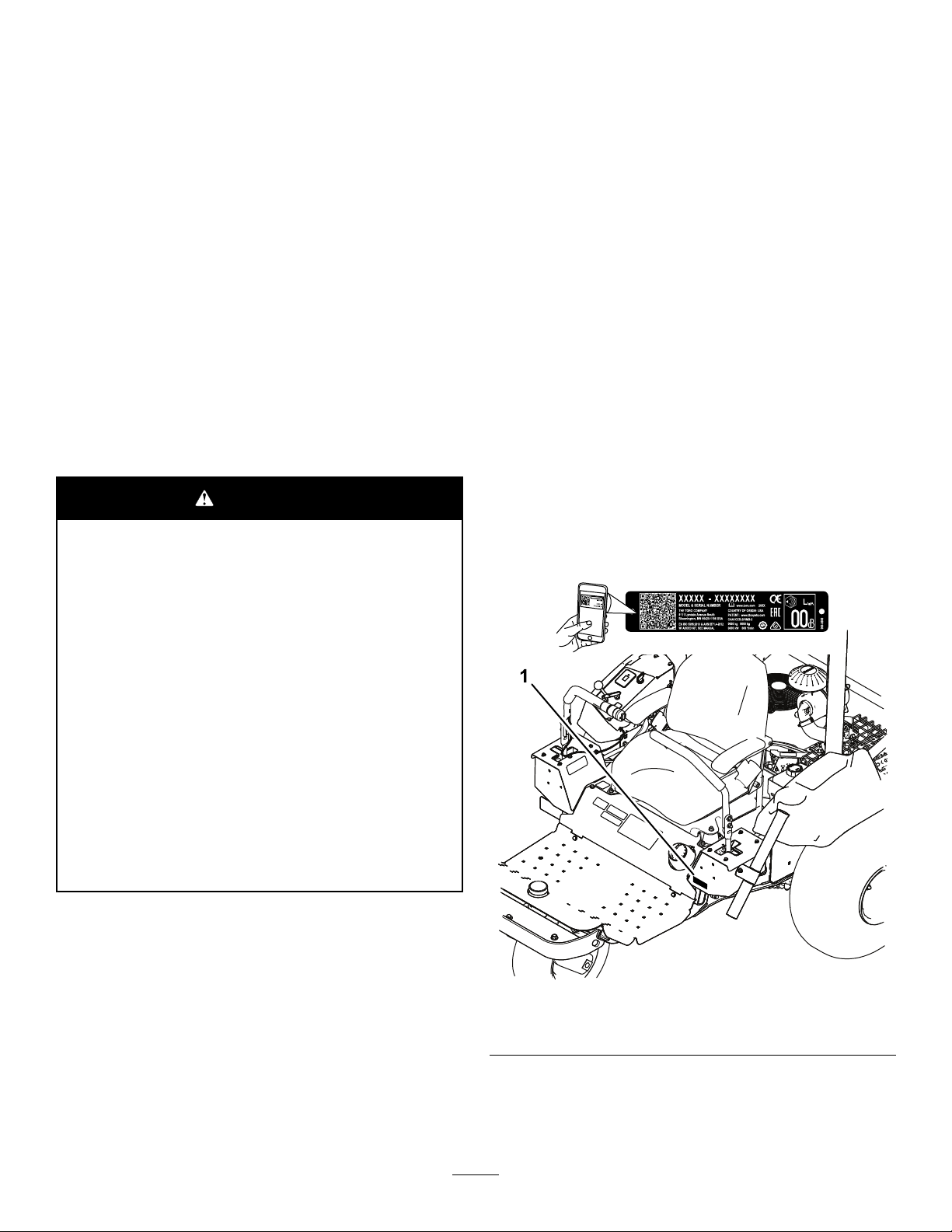
109-7232
1.Fast3.Neutral
2.Slow
decal109-7232
4.Reverse
1.Hourmeter4.Neutral
2.Powertake-off(PTO)5.Operator-presenceswitch
3.Parkingbrake6.Battery
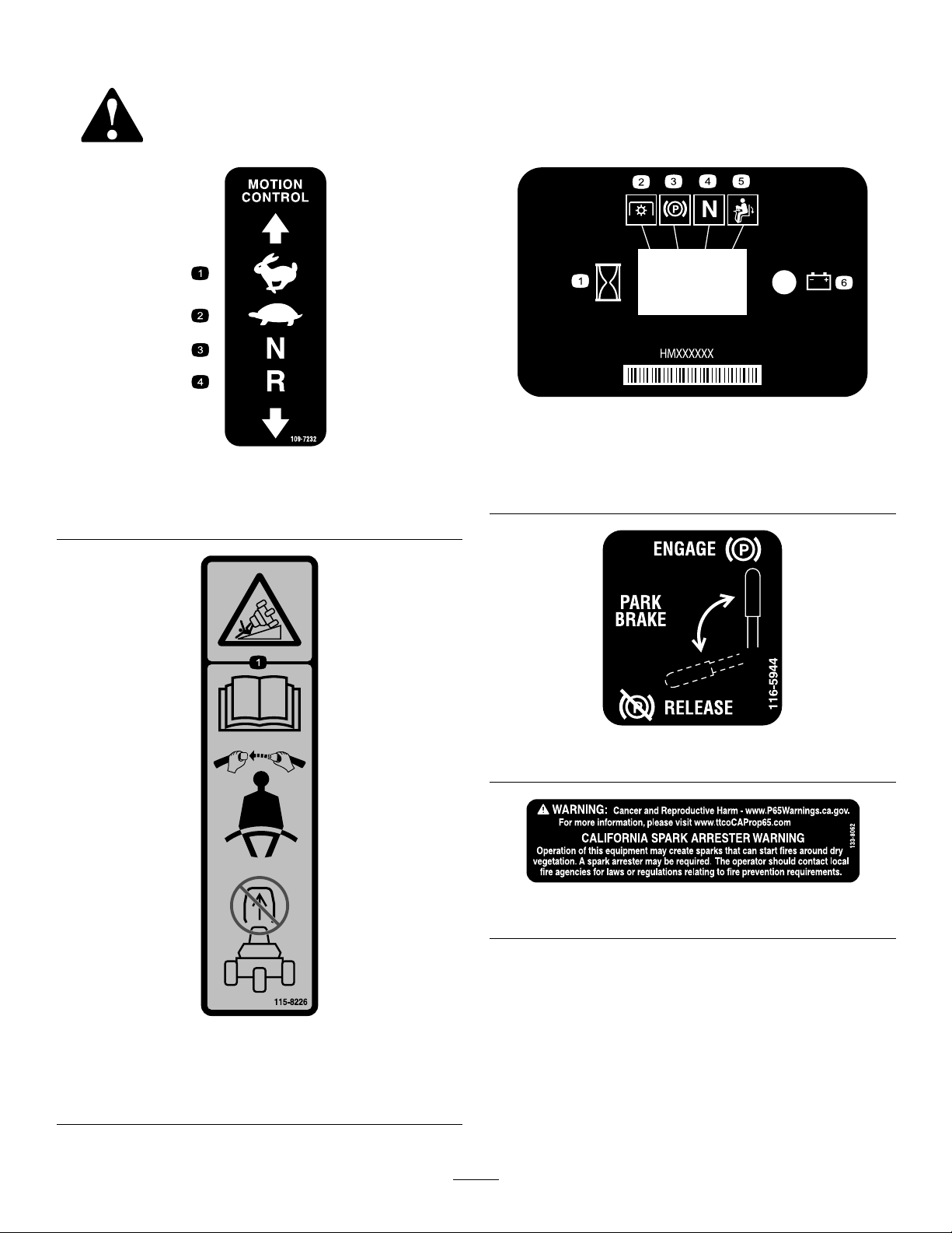
decal116-5944
116-5944
decal133-8062
133-8062
115-8226
1.Tippinghazard—readtheOperator'smanual;alwayswear
aseatbeltwhenoperating;donotremovetherollover
protectionsystem(ROPS).
decal115-8226
5
Page 6
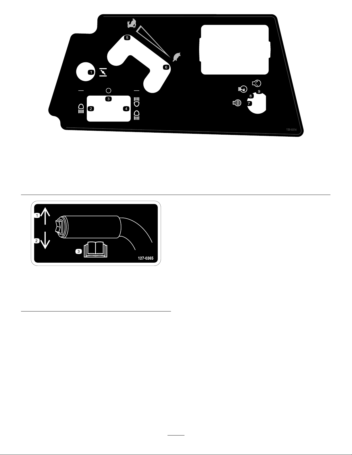
125–0214
1.Choke6.Slow
2.Headlight7.Engine—stop
3.Off
4.Headlightandtaillight9.Engine—start
5.Fast
decal127-0365
127–0365
decal125-0214
8.Engine—run
1.Pressuptoraisethe
attachment.
2.Pressdowntolowerthe
attachment.
3.ReadtheOperator’s
Manual.
6
Page 7
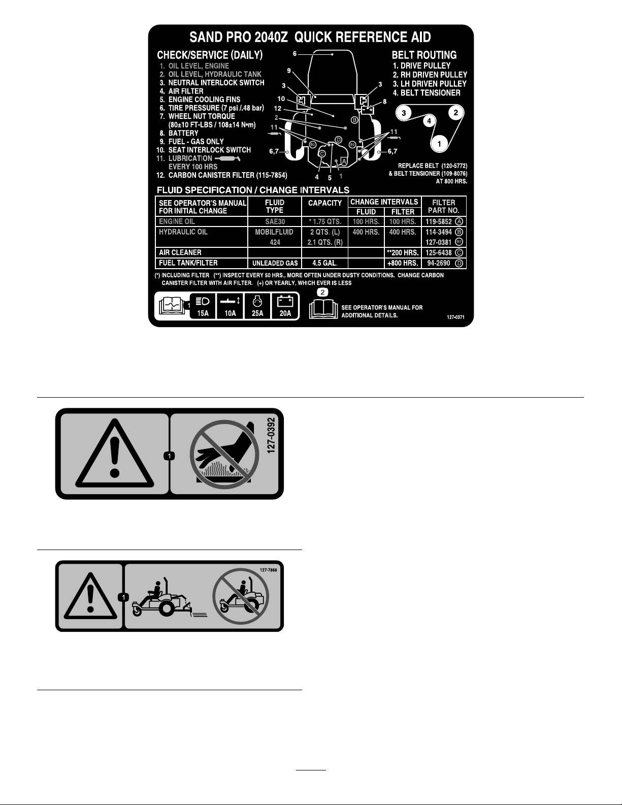
decal127-0371
127–0371
1.ReadtheOperator’sManualforinformationon
fuses—Headlights15A;Attachment10A;Enginestart25A;
Battery20A.
127–0392
1.Warning—keepawayformhotsurfaces.
127–7868
2.ReadtheOperator’sManual.
decal127-0392
decal127-7868
1.Warning—donotoperatethemachinewithoutthe
attachmentinstalled.
7
Page 8
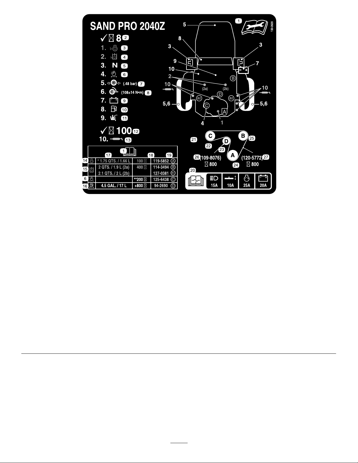
decal130-2620
130–2620
CEonly
1.ReadtheOperator’sManualforinformationonmaintenance.
15.Hydraulicoil
2.Checkevery8operatinghours.16.Fueltank/lter
3.Oillevel—engine17.Capacity
4.Oillevel—hydraulictank18.Serviceinterval
5.Neutralinterlockswitch19.Filterpartnumber
6.Airlter20.ReadtheOperator’sManualforinformationon
fuses—Headlights15A;Attachment10A;Enginestart25A;
Battery20A.
7.Tirepressure(0.48bar)
21.Beltrouting
8.Wheelnuttorque(61to75N∙m)22.Leftdrivenpulley
9.Battery
23.Belttensioner
10.Fuel—gasolineonly24.Drivepulley
11.Seatinterlockswitch
25.Rightdrivenpulley
12.Checkevery100operatinghours.26.Belttensioner—partnumber(replaceevery800operating
hours)
13.Lubrication
27.Belt—partnumber(replaceevery800hours)
14.Engineoil
8
Page 9
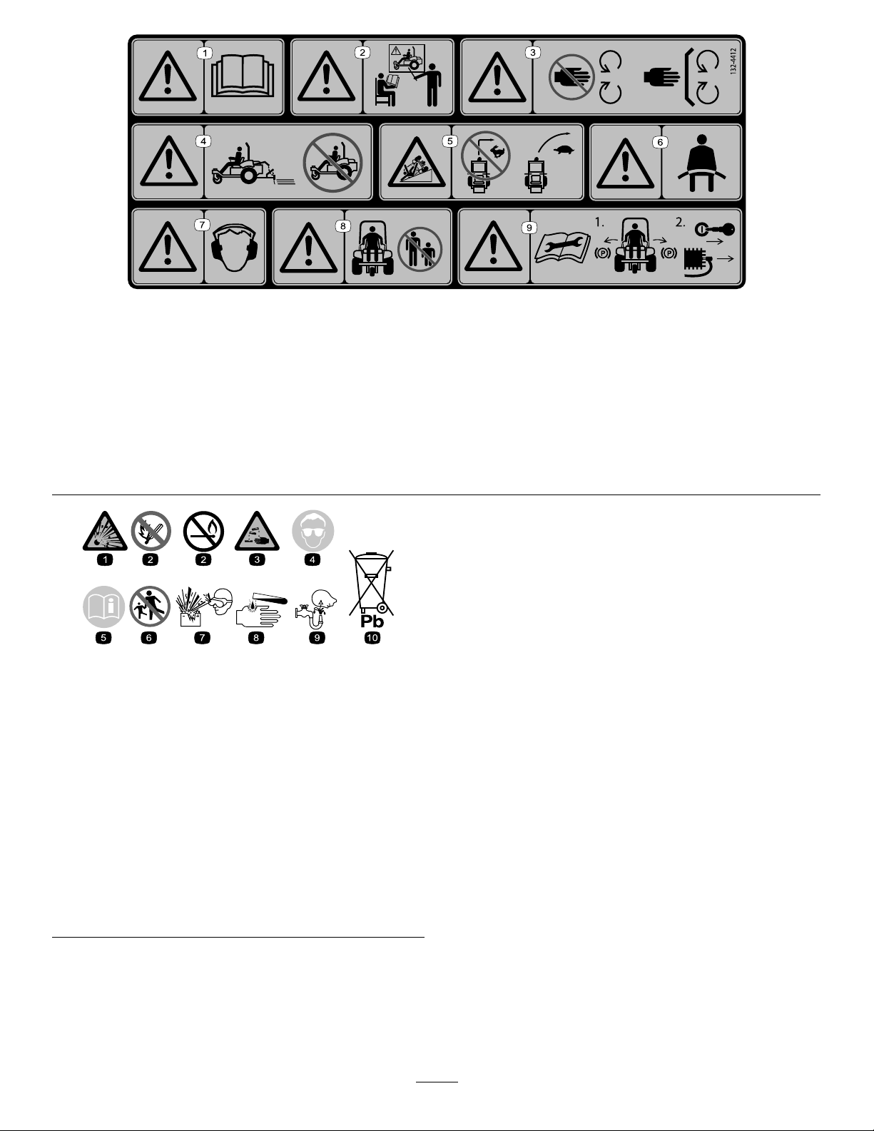
decal132-4412
132-4412
1.Warning—readtheOperator’sManual.
6.Warning—wearaseatbelt.
2.Warning—donotoperatethemachineunlessyouaretrained.7.Warning—wearhearingprotection.
3.Warning—keepawayfrommovingparts;keepallguardsand
8.Warning—keepbystandersaway.
shieldsinplace.
4.Warning—donotoperatethemachinewithouttheattachment
installed.
9.Warning—readtheOperator’sManualbeforeperforming
maintenance;1)Engagetheparkingbrakes;2)Removethe
keyfromtheignitionandremovethewirefromthesparkplug.
5.Tippinghazard,slopes—donotturnathighspeed;slowdown
andturngradually.
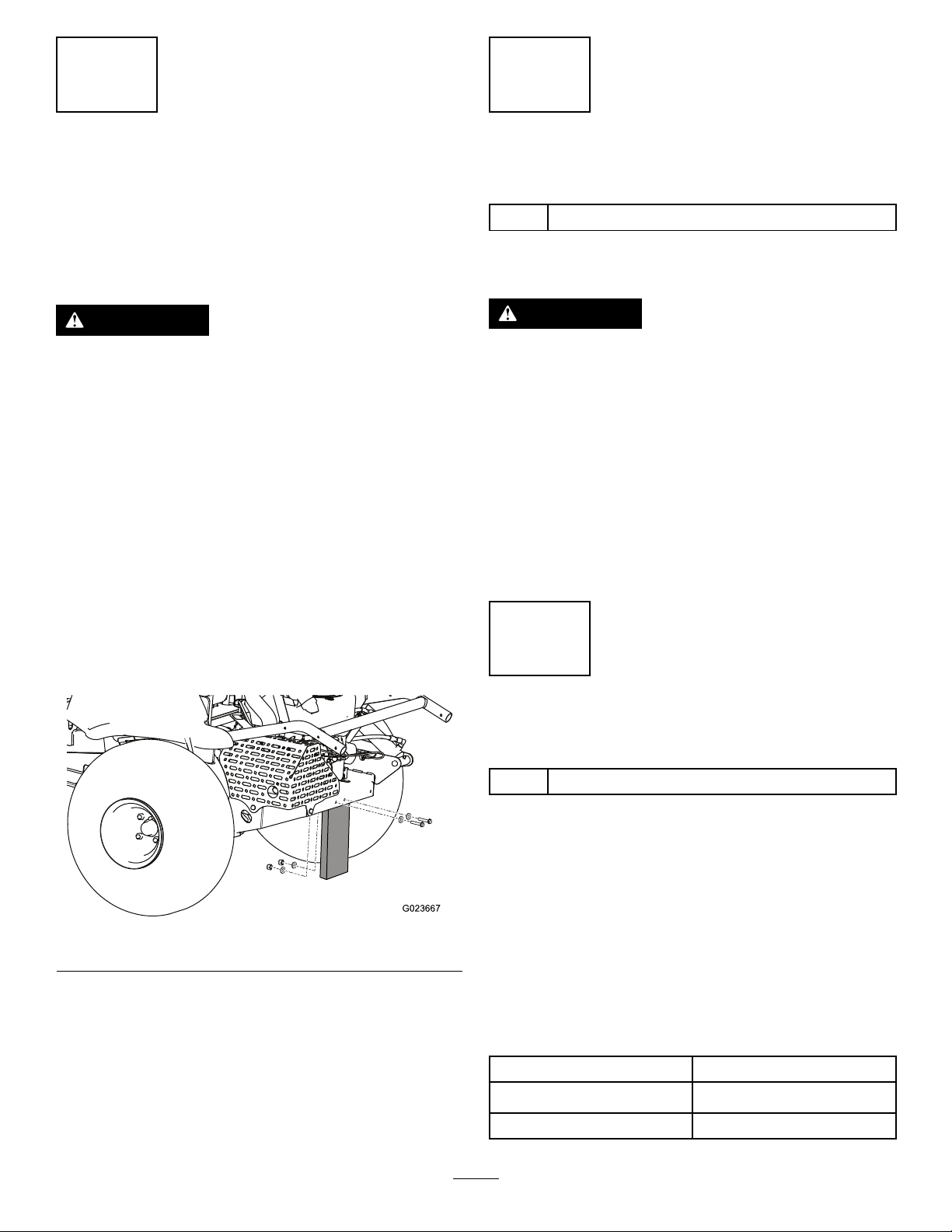
decalbatterysymbols
BatterySymbols
Someorallofthesesymbolsareonyourbattery
1.Explosionhazard
2.Nore,opename,or
smoking
3.Causticliquid/chemical
burnhazard
4.Weareyeprotection.9.Flusheyesimmediately
5.ReadtheOperator's
Manual.
6.Keepbystandersasafe
distanceawayfromthe
battery.
7.Weareyeprotection;
explosivegasescan
causeblindnessandother
injuries.
8.Batteryacidcancause
blindnessorsevereburns.
withwaterandgetmedical
helpfast.
10.Containslead;donot
discard;recycle
9
Page 10

Setup
LooseParts
Usethechartbelowtoverifythatallpartshavebeenshipped.
ProcedureDescription
1
2
3
4
5
6
Nopartsrequired
Attachmentandrelatedparts(sold
separately)
Frontweights(asneededper
attachment)
Bolt(5/16x3/4inch)
Nut(5/16inch)
Servicedecal(130-2620)
Rollbar1
Bolt4
Flangelocknut4
Springwasher
Bracket2
MediaandAdditionalParts
Description
Operator'sManual
Engineowner’smanual1
Pre-deliveryinspectionsheet1
CerticateofCompliance
Qty.
Qty.
–
–
–
1
2
1
4
1
Readthesheetbeforeoperating.
1
ThecerticateindicatesCEcompliance.
Removetheshippingboard.
Installanattachment.
Installthefrontweights.
Connectthebattery.
ApplytheCEservicedecal,ifrequired
(CEonly).
Installtherollbar.
Use
Use
Key2
Starttheengine.
Note:Determinetheleftandrightsidesofthemachinefromthenormaloperatingposition.
Note:Removeanddiscardalltheshippingbracketsandfasteners.
10
Page 11
1
2
RemovingtheShipping Board
NoPartsRequired
Procedure
WARNING
Ifyoudrivethemachinewithouttheshipping
boardoranattachmentinstalled,themachine
cantipoverandinjuresomeoneordamage
property.
Drivethemachineonlyiftheshippingboard
oranapprovedattachmentisinstalled.
Beforeyoucaninstallanattachmentonthemachine,
youmustremovetheshippingboard.
1.Parkthemachineonalevelsurface,movethe
controlhandlestotheneutral-lockedposition,
engagetheparkingbrake,shutofftheengine,
andremovethekey.
InstallinganAttachment
Partsneededforthisprocedure:
–
Attachmentandrelatedparts(soldseparately)
Procedure
WARNING
Ifyoudrivethemachinewithoutanattachment
installed,itcantipoverandinjuresomeone
ordamageproperty.
Drivethemachineonlyifthereisanapproved
attachmentinstalled.
Parkthemachineonalevelsurface,movethecontrol
handlestotheneutral-lockedposition,engagethe
parkingbrake,shutofftheengine,andremovethe
key.
RefertotheattachmentInstallationInstructionsfor
informationoninstallingtheattachment.
2.Removethenuts,bolts,andwasherssecuring
theshippingboardtotherearofthemachine
(Figure3).
Figure3
3.Discardthefastenersandtheshippingboard.
3
InstallingtheFrontWeights
Partsneededforthisprocedure:
–
Frontweights(asneededperattachment)
Procedure
Thismachinehasbeendesignedinaccordancewith
2006/42/ECandANSIB71.4-2012.
g023667
However,whenyouinstallattachmentsonthe
machine,youmustaddadditionalweighttothe
machine,asspecied,tocomplytothestandards.
Usethechartbelowtodeterminetheadditionalweight
required.Themachinecomeswith4weights.Each
attachmentcomeswiththenecessaryadditional
weights,ifrequired.
Attachment
Flextoothrake4
Numberofweightsrequired
Flextoothrakewithnishbrush
11
6
Page 12
Attachment
Naildrag6
Naildragwithnishdragmat
RefertoInstallingandRemovingtheWeights(page
17).
Numberofweightsrequired
8
4
ConnectingtheBattery
Partsneededforthisprocedure:
1
Bolt(5/16x3/4inch)
2
Nut(5/16inch)
Procedure
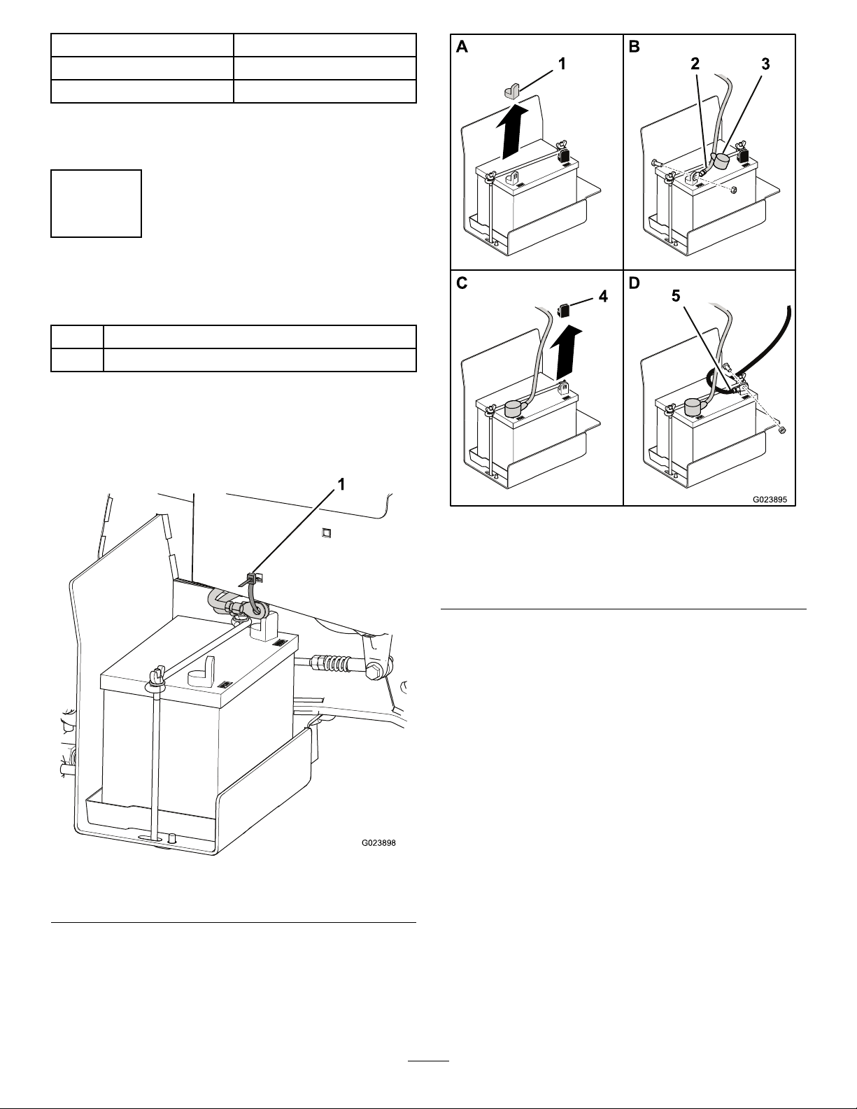
1.Cutthecabletiesecuringthebatterycablesto
theframe,anddiscardthecabletie(Figure4).
1.Cabletie
g023895
Figure5
1.Redcover4.Blackcover
2.Positivecable5.Negativecable
3.Boot
3.Slidetheredbootawayfromtheendofthe
positivebatterycable,anduseabolt(5/16x3/4
inch)andanut(5/16inch)tomountthepositive
cabletothepositivebatteryterminal.
4.Slidetheredbootovertheterminalandthe
fasteners.
5.Removetheblackplasticcoverfromthe
negativebatteryterminal.
6.Useabolt(5/16x3/4inch)andanut(5/16inch)
tomountthenegativecabletothenegative
batteryterminal.
g023898
Figure4
2.Removetheredplasticcoverfromthepositive
batteryterminal(Figure5).
12
Page 13
5
ApplyingtheCEService
Decal(CEOnly)
Partsneededforthisprocedure:
1
Servicedecal(130-2620)
Procedure
IfthismachinemustbeCEcompliant(Europe),apply
theCEservicedecal(130-2620)overtheexisting
servicedecal(127–0371).
6
g026804
Figure6
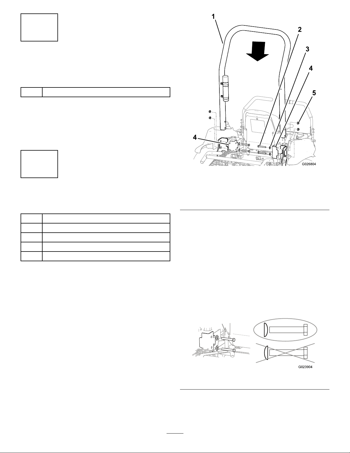
InstallingtheRollBar
Partsneededforthisprocedure:
1Rollbar
4Bolt
4Flangelocknut
4
Springwasher
2Bracket
Procedure
1.Removetherollbarfromthecrate.
2.Placetherollbaronthemachineasshownin
Figure6.
1.Rollbar
2.Bolt(4)5.Flangelocknut(4)
3.Springwasher(4)
3.Installthebracketsontheframeofthemachine.
Important:Ensurethatthethrottlecable
andthechokecableareoutoftheway,so
thattheydonotgetpinchedbytherollbar
orabracket.
4.Aligntheholesinthebrackets,therollbar,and
theframe.
5.Installabolt,withaspringwasher,througheach
hole.
Important:Ensurethateachspringwasher
ispositionedsothattheconvexsidefaces
theboltheadasshowninFigure7.
4.Bracket(2)
Figure7
6.Installaangelocknutoneachbolt,andtorque
eachofthemto102N∙m(75ft-lb).
13
g023904
Page 14
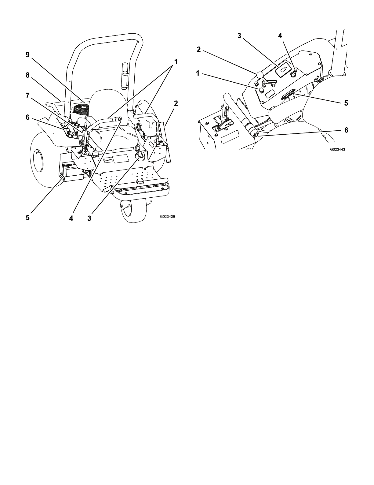
ProductOverview
Controls
g023443
Figure9
1.Control
handles
2.Raketube5.Battery
3.Fuel-tankcap
Figure8
4.Attachment
switch
6.Controlpanel
7.Parkingbrake
8.Attachmentlift
9.Engine
1.Chokecontrol
2.Throttlelever5.Fuses
3.Hourmeter;
safety-interlockdisplay
4.Ignitionswitch
6.Attachmentswitch
ControlHandles
g023439
Usethecontrolhandles(Figure8)todrivethe
machineforwardandbackward,andtoturnineither
direction.
IgnitionSwitch
Theignitionswitch(Figure9),usedtostartandshut
offtheengine,has3positions:OFF,RUN,andST ART.
RotatethekeyclockwisetotheSTARTpositiontostart
theengine.Releasethekeywhentheenginestarts.
ThekeywillmoveautomaticallytotheRUNposition.
Toshutofftheengine,rotatethekeycounterclockwise
totheOFFposition.
ChokeControl
Tostartacoldengine,closethecarburetorchokeby
pullingthechokecontrol(Figure9)uptotheCLOSED
position.Aftertheenginestarts,regulatethechoke
tokeeptheenginerunningsmoothly.Assoonas
possible,openthechokebypushingthecontroldown
totheOPENposition.
Note:Awarmenginerequireslittleornochoking.
14
Page 15
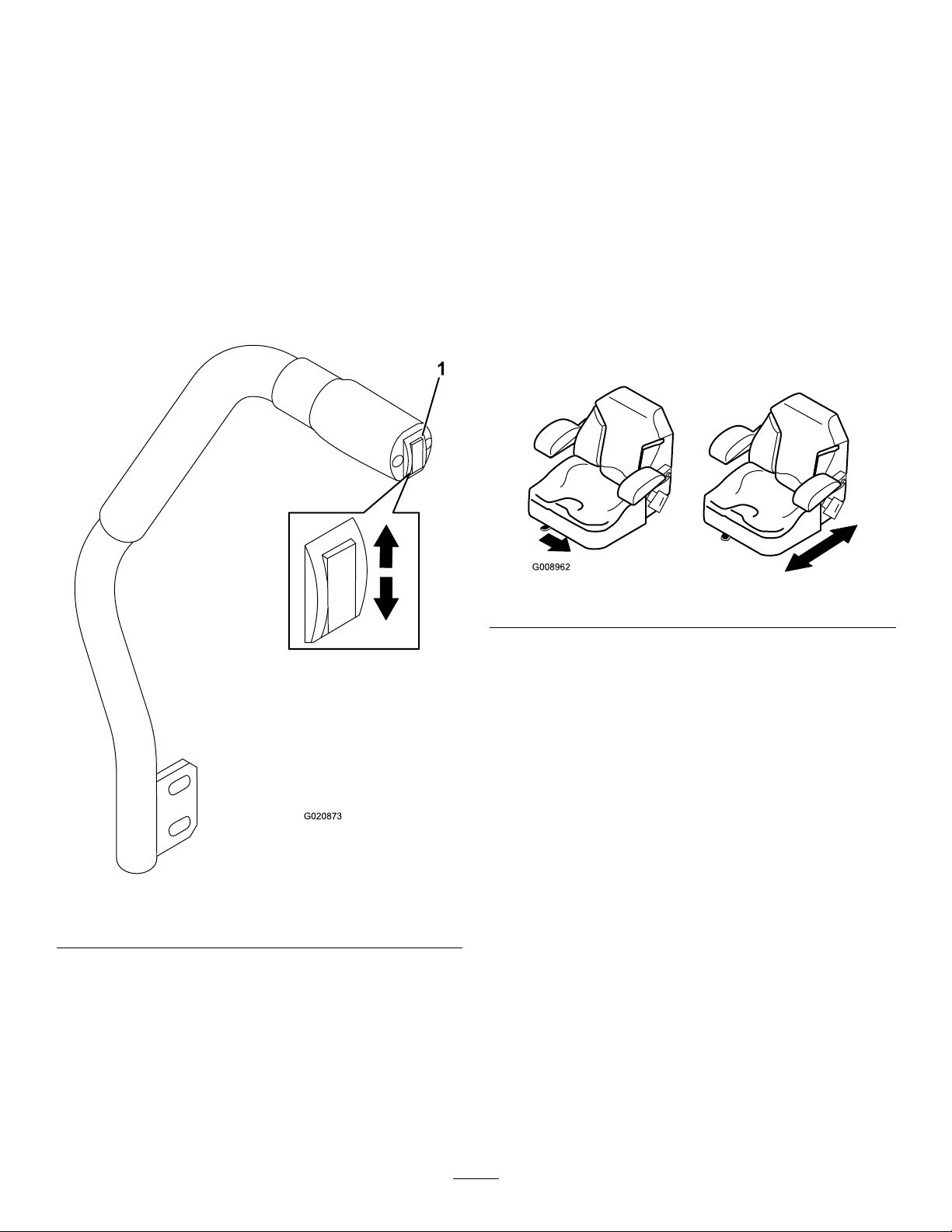
ThrottleLever
HourMeter
Thethrottlelever(Figure9)controlsthespeedofthe
engine.Movingthethrottleleverforwardtowardthe
FASTpositionincreasestheenginespeed.Movingit
backwardtowardtheSLOWpositiondecreasesthe
enginespeed.
Note:Thethrottlelevercannotshutofftheengine.
AttachmentSwitch
Toraisetheattachment,presstheupperpartof
theattachmentswitch(Figure10);tolowerthe
attachment,pressthelowerpartoftheattachment
switch.
Thehourmeter(Figure9)indicatesthetotalhoursof
machineoperation.Thehourmeterrunswhenever
theignitionswitchisintheONposition,aslongasthe
batteryisfullycharged(13.8Vormore)oryouare
sittingintheseat,therebyactivatingtheseatswitch.
Anoptionalwirelesshourmeterisavailablethrough
yourAuthorizedT oroDistributor.Toinstallit,referto
InstallingaWirelessHourMeter(page29).
Seat-AdjustmentLever
Whilesittingontheseat,movetheleverinfrontofthe
seat(Figure11)totheleft,andslidetheseattothe
desiredposition.Releasethelevertolocktheseat
intoposition.
Figure10
1.Attachmentswitch
Note:Themachinehasadouble-actingliftcylinder.
Youcanapplydownpressuretotheattachmentfor
certainoperatingconditions.
g008962
Figure11
g020873
ParkingBrake
Toengagetheparkingbrake(Figure8),pullbackon
theleveroftheparkingbrake.T odisengageit,push
theleverforward.
15
Page 16

Specications
Note:Specicationsanddesignaresubjecttochangewithoutnotice.
Machineonly
Weight
Width
Length
Height
Wheelbase
*with4weights,emptyfueltank,andnooperator
**withtheattachmentandweights,emptyfueltank,andnooperator
399kg(880lb)*417kg(920lb)**439kg(970lb)**445kg(980lb)**
147cm(58inches)213cm(84inches)182cm(71.5inches)198cm(78inches)
186cm(73.3inches)226cm(89.0inches)215cm(84.8inches)297cm(1 17inches)
Withextoothrake
Attachments/Accessories
AselectionofT oroapprovedattachmentsand
accessoriesisavailableforusewiththemachine
toenhanceandexpanditscapabilities.Contact
yourAuthorizedServiceDealerorDistributoror
gotowww.Exmark.comforalistofallapproved
attachmentsandaccessories.
Tobestprotectyourinvestmentandmaintainoptimal
performanceofyourToroequipment,countonToro
genuineparts.Whenitcomestoreliability,Toro
deliversreplacementpartsdesignedtotheexact
engineeringspecicationofourequipment.Forpeace
ofmind,insistonTorogenuineparts.
WithnaildragWithnaildragand
nishmat
185cm(73inches)
147cm(58inches)
Operation
Note:Determinetheleftandrightsidesofthe
machinefromthenormaloperatingposition.
BeforeOperation
BeforeOperationSafety
GeneralSafety
•Neverallowchildrenoruntrainedpeopleto
operateorservicethemachine.Localregulations
mayrestricttheageoftheoperator.Theowner
isresponsiblefortrainingalloperatorsand
mechanics.
•Becomefamiliarwiththesafeoperationofthe
equipment,operatorcontrols,andsafetysigns.
•Parkthemachineonalevelsurface;engagethe
parkingbrake,shutofftheengine,removethekey,
andwaitforallmovementtostopbeforeleaving
themachine.
•Knowhowtostopthemachineandenginequickly.
•Checkthatoperator-presencecontrols,safety
switches,andshieldsareattachedandfunctioning
properly.Donotoperatethemachineunlessthey
arefunctioningproperly.
•Beforeoperating,alwaysinspectthemachine
toensurethatthecomponentsandfasteners
areingoodworkingcondition.Replacewornor
damagedcomponentsandfasteners.
FuelSafety
•Useextremecareinhandlingfuel.Itisammable
anditsvaporsareexplosive.
•Extinguishallcigarettes,cigars,pipes,andother
sourcesofignition.
16
Page 17
•Useonlyanapprovedfuelcontainer.
•Donotremovethefuelcaporllthefueltank
whiletheengineisrunningorhot.
•Donotaddordrainthefuelinanenclosedspace.
•Donotstorethemachineorfuelcontainerwhere
thereisanopename,spark,orpilotlight,such
asonawaterheaterorotherappliance.
•Ifyouspillfuel,donotattempttostarttheengine;
avoidcreatinganysourceofignitionuntilthefuel
vaporshavedissipated.
BreakingintheMachine
Newenginestaketimetodevelopfullpower.Drive
systemshavemorefrictionwhentheyarenew,
placingadditionalloadontheengine.
Allowtherst8hoursofoperatingtimeforthe
break-inperiod.
Sincethersthoursofoperationarecriticaltofuture
dependabilityofthemachine,monitorthefunctions
andperformancecloselysothatyoucannoticeand
correctminordifculties,whichcouldleadtomajor
problems.Inspectthemachinefrequentlyduring
thebreak-inperiod,forsignsofoilleakage,loose
fasteners,oranyothermalfunction.
InstallingandRemoving theWeights
ThemachinecomplieswiththeANSIB71.4-2012
standardsatthetimeofproduction.However,
whenthefollowingattachmentsareinstalledonthe
machine,additionalweightisrequiredtocomplyto
thestandards.Usethechartbelowtodeterminethe
additionalweightrequired.Themachinecomeswith4
weights.Eachattachmentcomeswiththenecessary
additionalweights,ifrequired.
Attachment
Flextoothrake4
Flextoothrakewithnishbrush
Naildrag6
Naildragwithnishdragmat
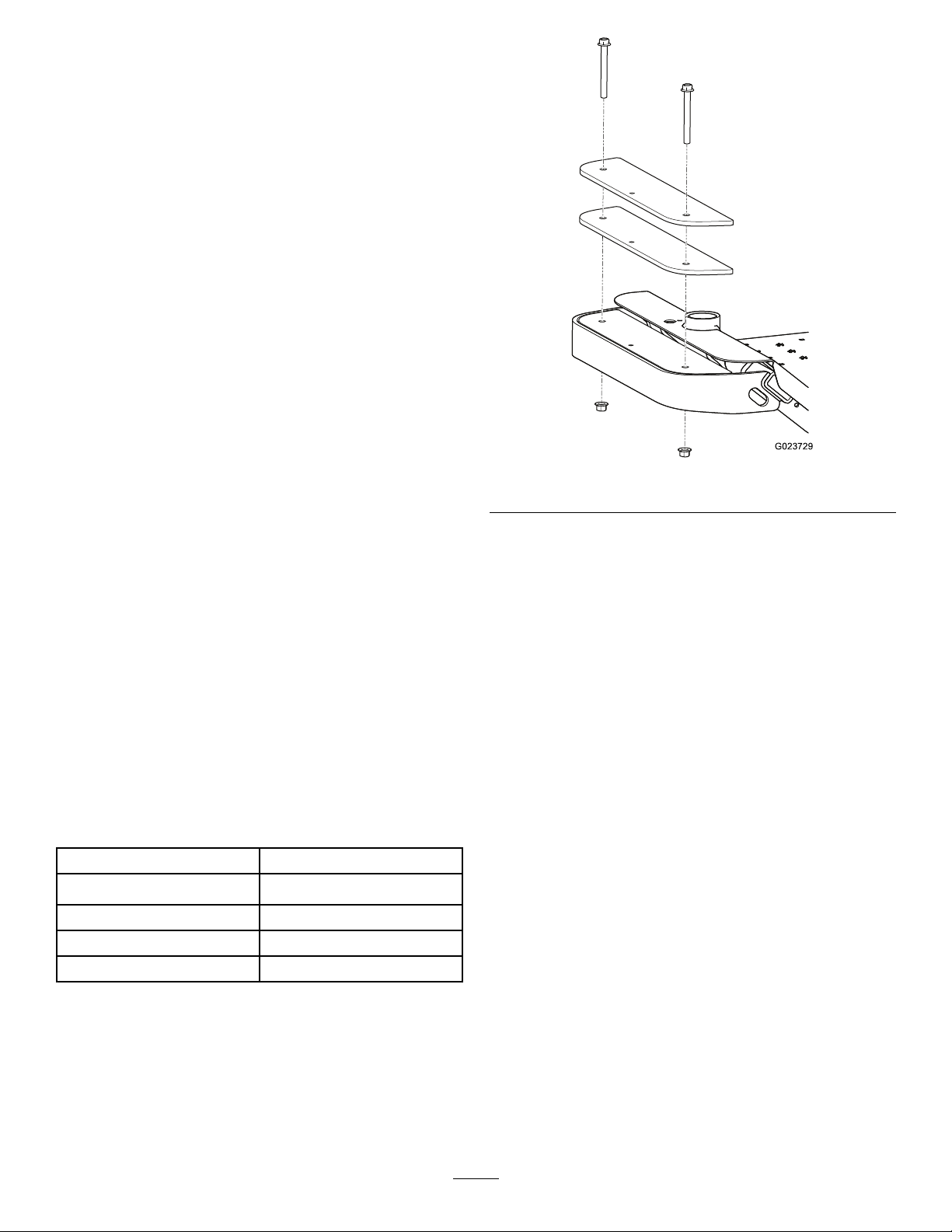
1.Removethe2boltsand2nutssecuringthe
existingweightsonthefrontofthemachine
(Figure12).
Note:Ifthemachineisequippedwiththelight
kit,removethenutandtheboltsecuringthe
frontlighttothemachine.Retainalloftheparts;
refertotheLightKitInstallationInstructions.
Numberofweightsrequired
6
8
g023729
Figure12
2.Addorremoveweightsasnecessary.
3.Securetheweightswiththe2boltsandthe2
nuts.
•Formostoftheattachments,usetheexisting
bolts.
•Thenishdragmatincludes2longerbolts
toaccommodatetheadditionalweightsthat
itrequires.
Note:Ifthemachineisequippedwiththelight
kit,installthefrontlightbyinsertingthebolt
throughtheweightsandsecuringitwiththenut;
refertotheLightKitInstallationInstructions.
CheckingtheLevelofthe EngineOil
ServiceInterval:Beforeeachuseordaily—Check
theleveloftheengineoil.
ToroPremiumEngineOilisavailablefromyour
AuthorizedT oroDistributor.
CrankcaseCapacity:1.8L(1.7USqt)withlter
change
Use4-cycleengineoilthatmeetsorexceedsthe
followingrequirements:
•APIservicecategory:SJ,SL,SM,orhigher
•Viscosity:SAE30;refertothefollowingchartfor
otherviscosities(Figure13):
17
Page 18

Important:Usingmulti-viscosityoils,suchas
10W-30,increasesoilconsumption.Checkthe
oillevelmorefrequentlywhenusingthem.
Figure13
1.Parkthemachineonalevelsurface,lowerthe
attachment,movethecontrolhandlestothe
neutral-lockedposition,engagetheparking
brake,shutofftheengine,andremovethekey.
2.Removethedipstick(Figure14)andwipeitwith
acleancloth(Figure15).
g023445
g008792
Figure15
3.Insertthedipstickintothelltubewithout
threadingitintotheport.
4.Removethedipstickfromthetubeandcheck
g023517
Figure14
theoillevel.Iftheoillevelislow,slowlypour
onlyenoughoilintothelltubetoraisetheoil
leveltotheupper-limitmarkonthedipstick
1.Dipstick
Important:Keeptheengineoillevel
betweentheupperandlowerlimitsonthe
dipstick.Enginefailuremayoccurasaresult
ofrunningtheenginewithtoomuchortoo
littleengineoil.
5.Installthedipstickrmlyinplace.
Important:Thedipstickmustbefullyseated
inthetubetoprovidepropersealingof
theenginecrankcase.Failuretosealthe
crankcasemayresultinenginedamage.
18
Page 19

FillingtheFuelTank
CheckingtheLevelofthe
Fueltankcapacity:17L(4.5USgallons)
RecommendedFuel:
•Forbestresults,useonlyclean,fresh(lessthan
30daysold),unleadedgasolinewithanoctane
ratingof87orhigher((R+M)/2ratingmethod).
•Ethanol:Gasolinewithupto10%ethanol
(gasohol)or15%MTBE(methyltertiarybutyl
ether)byvolumeisacceptable.EthanolandMTBE
arenotthesame.Gasolinewith15%ethanol
(E15)byvolumeisnotapprovedforuse.Never
usegasolinethatcontainsmorethan10%ethanol
byvolume,suchasE15(contains15%ethanol),
E20(contains20%ethanol),orE85(contains85%
ethanol).Usingunapprovedgasolinemaycause
performanceproblemsand/orenginedamage
whichmaynotbecoveredunderwarranty.
•Donotusegasolinecontainingmethanol.
•Donotstorefueleitherinthefueltankorfuel
containersoverthewinterunlessafuelstabilizer
isused.
•Donotaddoiltogasoline.
1.Parkthemachineonalevelsurface,lowerthe
attachment,movethecontrolhandlestothe
neutral-lockedposition,engagetheparking
brake,shutofftheengine,andremovethekey.
2.Cleantheareaaroundthefuel-tankcap(Figure
16).
HydraulicFluid
ServiceInterval:Beforeeachuseordaily—Check
thelevelofthehydraulicuid.
Important:Foraccuracy,checkthelevelofthe
hydraulicuidonlywhentheengineandthe
hydraulicsystemarecold.
Thereservoirsofthemachinearelledatthefactory
withhigh-qualityhydraulicuid.Thebesttimeto
checkthehydraulicuidiswhentheuidiscold.The
machineshouldbeinthetransportconguration.If
theuidlevelisbelowthetopofthehorizontalpartof
thecut-outsightwindowontherearofthehydraulic
reservoirs(Figure17),adduidtobringtheuidto
theacceptablelevel.Donotoverllthereservoirs.
Iftheuidlevelisatthetopofthehorizontalpartof
thesightwindow,nouidadditionisrequired.The
recommendedreplacementuidis:
FluidType:T oroPremiumTransmission/Hydraulic
TractorFluidorMobiluid
Capacity:
•Leftside—1.9L(2.0USqt)
•Rightside—2.0L(2.1USqt)
Alternativeuids:Ifthespecieduidisnotavailable,
otheruniversaltractorhydraulicuids(UTHF)may
beused,buttheymustbeonlyconventional,
petroleum-basedproducts,notsyntheticsor
biodegradableuids.Thespecicationsmustfall
withinthelistedrangeforallofthefollowingmaterial
propertiesandtheuidshouldmeetlistedindustry
standards.Checkwithyouruidsuppliertoseeifthe
uidmeetsthesespecications.
®
424
Figure16
1.Fuel-tankcap
3.Removethefuel-tankcap.
4.Fillthetanktoabout25mm(1inch)belowthe
topofthetank(bottomofthellerneck).Donot
overll.
5.Installthecap.
6.Wipeupanyfuelthatmayhavespilled,to
preventarehazard.
Note:T orowillnotassumeresponsibilityfordamage
causedbyimpropersubstitutions,souseonly
productsfromreputablemanufacturerswhowillstand
behindtheirrecommendation.
g023449
19
Page 20

MaterialProperties:
Viscosity,ASTMD445cSt@40°C(104°F)55to62
ViscosityIndexASTMD2270
PourPoint,ASTMD97-37°Cto-43°C(-35°Fto-46°F)
IndustrySpecications:
APIGL-4,AGCOPoweruid821XL,FordNewHolland
FNHA-2-C-201.00,KubotaUDT ,JohnDeereJ20C,Vickers
35VQ25,andVolvoWB-101/BM
140to152
Note:Manyhydraulicuidsarealmostcolorless,
makingitdifculttospotleaks.Areddyeadditive
forthehydraulicuidisavailablein20ml(2/3oz)
bottles.Onebottleissufcientfor15to22L(4to
6USgallons)ofhydraulicuid.Orderpartnumber
44-2500fromyourAuthorizedT oroDistributor.
A.Cleantheareaaroundtheuid-reservoir
capstopreventdebrisfromenteringthe
system(Figure17).
B.Removethecapsfromthereservoirs.
C.Slowlyllthereservoirwiththeappropriate
hydraulicuiduntilthelevelreachesthe
bottomoftheopeningsinthebrackets.
Important:Topreventsystem
contamination,cleanthetopoftheuid
containerbeforeopeningit.Ensurethat
thepourspoutandthefunnelareclean.
Important:Donotoverllthereservoirs.
D.Installthereservoircaps.
1.Parkthemachineonalevelsurface,lowerthe
attachment,engagetheparkingbrake,shutoff
theengine,andremovethekey.
2.Lookattheopeningineachoftheuid-reservoir
brackets,andcheckthelevelofthehydraulic
uid.
Note:Theuidlevelshouldbeatthebottomof
eachoftheopenings,asshowninFigure17.
CheckingtheTirePressure
ServiceInterval:Beforeeachuseordaily
Parkthemachineonalevelsurface,lowerthe
attachment,engagetheparkingbrake,shutoffthe
engine,andremovethekey .
Checkthetirepressurebeforeoperatingthemachine
(Figure18).
Pressure:48kPa(7psi)
Figure17
1.Hydraulic-uidreservoirs
2.Fluid-reservoircap4.Fluidlevel
3.Bracket
3.Iftheuidlevelislowineitherofthereservoirs,
adduidasfollows:
g002706
Figure18
1.Valvestem2.Lugnut
TorquingtheWheelLug
g023450
Nuts
ServiceInterval:Aftertherst8hours
Every100hours
Parkthemachineonalevelsurface,lowerthe
attachment,engagetheparkingbrake,shutoffthe
engine,andremovethekey .
20
Page 21

Torquethelugsnuts(Figure18)to61to75N∙m(45
to55ft-lb).
DuringOperation
DuringOperationSafety
GeneralSafety
•Theowner/operatorcanpreventandisresponsible
foraccidentsthatmaycausepersonalinjuryor
propertydamage.
•Wearappropriateclothing,includingeye
protection;longpants;substantial,slip-resistant
footwear;andhearingprotection.Tiebacklong
hairanddonotwearlooseclothingorloose
jewelry.
•Useyourfullattentionwhileoperatingthe
machine.Donotengageinanyactivitythat
causesdistractions;otherwise,injuryorproperty
damagemayoccur.
•Donotoperatethemachinewhileill,tired,or
undertheinuenceofalcoholordrugs.
•Nevercarrypassengersonthemachineandkeep
bystandersandpetsawayfromthemachine
duringoperation.
•Operatethemachineonlyingoodvisibilitytoavoid
holesorhiddenhazards.
•Beforeyoustarttheengine,ensurethatalldrives
areinneutral,theparkingbrakeisengaged,and
youareintheoperatingposition.
•Lookbehindanddownbeforebackinguptobe
sureofaclearpath.
•Usecarewhenapproachingblindcorners,shrubs,
trees,orotherobjectsthatmayobscureyour
vision.
•Stopthemachineandinspecttheattachment
afterstrikinganobjectorifthereisanabnormal
vibrationinthemachine.Makeallnecessary
repairsbeforeresumingoperation.
•Slowdownandusecautionwhenmakingturns
andcrossingroadsandsidewalkswiththe
machine.Alwaysyieldtheright-of-way.
•Neverrunanengineinanareawhereexhaust
gassesareenclosed.
•Neverleavearunningmachineunattended.
•Beforeleavingtheoperatingposition,dothe
following:
–Parkthemachineonlevelground.
–Lowertheattachments.
–Engagetheparkingbrake.
–Shutofftheengineandremovethekey.
–Waitforallmovingpartstostop.
•Donotoperatethemachinewhenthereistherisk
oflightning.
•Donotusethemachineasatowingvehicle.
•Whennecessary ,wetsurfacespriortoconditioning
tominimizedustcreation.
•Useaccessories,attachments,andreplacement
partsapprovedbyTheT oro®Companyonly.
RolloverProtectionSystem (ROPS)Safety
•DonotremovetheROPSfromthemachine.
•Ensurethattheseatbeltisattachedandthatyou
canreleaseitquicklyinanemergency.
•Checkcarefullyforoverheadobstructionsanddo
notcontactthem.
•KeeptheROPSinsafeoperatingconditionby
thoroughlyinspectingitperiodicallyfordamage
andkeepingallthemountingfastenerstight.
•ReplaceadamagedROPS.Donotrepairoralter
it.
•TheROPSisanintegralsafetydevice.
•Alwayswearyourseatbelt.
SlopeSafety
•Establishyourownproceduresandrulesfor
operatingonslopes.Theseproceduresmust
includesurveyingthesitetodeterminewhich
slopesaresafeformachineoperation.Always
usecommonsenseandgoodjudgmentwhen
performingthissurvey.
•Slopesareamajorfactorrelatedtolossofcontrol
androlloveraccidents,whichcanresultinsevere
injuryordeath.Theoperatorisresponsiblefor
safeslopeoperation.Operatingthemachineon
anysloperequiresextracaution.
•Slopesareamajorfactorrelatedtoloss-of-control
andtip-overaccidents,whichcanresultinsevere
injuryordeath.Operatingthemachineonany
sloperequiresextracaution.
•Operatethemachineatalowerspeedwhenyou
areonaslope.
•Ifyoufeeluneasyoperatingthemachineona
slope,donotdoit.
•Watchforholes,ruts,bumps,rocks,orother
hiddenobjects.Uneventerraincouldoverturnthe
machine.T allgrasscanhideobstacles.
•Choosealowgroundspeedsoyouwillnothave
tostoporshiftwhileonaslope.
•Arollovercanoccurbeforethetireslosetraction.
21
Page 22

•Avoidoperatingthemachineonwetgrass.Tires
maylosetraction;regardlessifthebrakesare
availableandfunctioning.
3.PullthechokecontrolupwardtotheONposition
(whenstartingacoldengine),andmovethe
throttlelevertotheSLOWposition.
•Avoidstarting,stopping,orturningthemachine
onaslope.
•Keepallmovementonslopesslowandgradual.
Donotsuddenlychangethespeedordirectionof
themachine.
•Donotoperatethemachineneardrop-offs,
ditches,embankments,orbodiesofwater.The
machinecouldsuddenlyrolloverifawheelgoes
overtheedgeortheedgecavesin.Establisha
safetyareabetweenthemachineandanyhazard
(2machinewidths).
StartingandShuttingOff theEngine
1.Movethecontrolhandlestotheneutral-locked
position(Figure19).
Important:Whenoperatingthemachine
intemperatureslessthan0°C(32°F)allow
themachinetimetowarmupbeforeusing
it.Thispreventsdamagetothehydraulic
system.
4.Insertthekeyintotheignitionswitchandrotate
itclockwisetostarttheengine.Releasethekey
whentheenginestarts.Regulatethechoketo
keeptheenginerunningsmoothly.
Important:Topreventoverheatingofthe
startermotor,donotkeeptheignitionkey
intheST ARTpositionforlongerthan10
seconds.After10secondsofcontinuous
cranking,wait60secondsbeforeusingthe
startermotoragain.
5.Toshutofftheengine,movethethrottlecontrol
totheSLOWposition,andturnthekeytothe
OFFposition.Removethekeyfromtheswitch
topreventaccidentalstarting.
Note:Inanemergency,simplyturnthekeyto
theOFFposition.
Figure19
1.Controlhandle
(neutral-lockedposition)
2.Center,unlockedposition5.Frontofthemachine
3.Forward
4.Backward
UsingtheParkingBrake
Alwaysengagetheparkingbrakewhenyoustopthe
machineorleaveitunattended.
EngagingtheParkingBrake
WARNING
Theparkingbrakemaynotholdthemachine
parkedonaslopeandcouldcausepersonal
injuryorpropertydamage.
Donotparkonslopesunlessthewheelsare
chockedorblocked.
Toengagetheparkingbrake,pullupwardonthe
handle(Figure20).
g004532
2.Engagetheparkingbrake;refertoEngagingthe
ParkingBrake(page22).
g016994
Figure20
22
Page 23

DisengagingtheParkingBrake
Todisengagetheparkingbrake,pushdownwardon
thehandle(Figure21).
Figure21
UsingtheSafetyInterlock System
CAUTION
Ifthesafetyinterlockswitchesare
disconnectedordamaged,themachinecould
operateunexpectedly,causingpersonal
injury.
•Donottamperwiththeinterlockswitches.
•Checktheoperationoftheinterlock
switchesdaily,andreplaceanydamaged
switchesbeforeoperatingthemachine.
Thesafetyinterlocksystemisdesignedtopreventthe
enginefromstartingunless:
•Theparkingbrakeisengaged.
•Thecontrolhandlesareintheneutral-locked
position
Thesafetyinterlocksystemalsostopstheengine
whenyoumovethecontrolhandlesoutofthe
neutral-lockedpositionwhileyouareoutoftheseator
whiletheparkingbrakeisset.
Thehourmeterhassymbolstonotifyyouwhenthe
interlockcomponentisinthecorrectposition.When
thecomponentisinthecorrectposition,atriangle
appearsinthecorrespondinglocation(Figure22).
g016995
1.Trianglesappearwhentheinterlockcomponentsareinthe
correctposition.
Figure22
g023660
Note:ThePTO(powertake-off)interlockisnotused
onthismachine.
TestingtheSafetyInterlock System
ServiceInterval:Beforeeachuseordaily
Ifthesafetyinterlocksystemdoesnotoperateas
describedbelow,haveanAuthorizedToroDistributor
repairitimmediately.
1.Sitontheseat,movethecontrolhandlestothe
neutralposition,andengagetheparkingbrake.
2.Starttheengine.
3.Getofftheseatandslowlymoveeachcontrol
handleforwardandbackward.
Theengineshouldshutoffin1to3secondsafter
movingeithercontrolhandleineitherdirection.
Ifitdoesnot,correcttheproblem.Repeatsteps
2and3fortheothercontrolhandle.
4.Sittingontheseat,engagetheparking
brake.Moveeithercontrolhandleoutofthe
neutral-lockedposition.Trystartingtheengine;
theengineshouldnotcrank.Repeatthisstep
fortheothercontrolhandle.
23
Page 24

DrivingtheMachine
CAUTION
Operatingthemachinedemandsattentionto
preventtippingorlossofcontrol.
•Usecarewhenenteringandleavingsand
traps.
•Useextremecautionaroundditches,
creeks,orotherhazards.
•Usecautionwhenoperatingthemachine
onasteepslope.
•Reduceyourspeedwhenmakingsharp
turnsorwhenturningonhillsides.
•Avoidsuddenstopsandstarts.
•Donotgofromreversetofullforward
withoutrstcomingtoacompletestop.
CAUTION
UsingtheControlHandles
Themachinecanspinveryrapidly.Ifyou
misusethecontrolhandles,youmaylose
controlofthemachineandinjuresomeoneor
damagethemachineorotherproperty.
•Usecautionwhenmakingturns.
•Slowthemachinedownbeforemaking
sharpturns.
Figure23
1.Controlhandle
(neutral-lockedposition)
2.Center,unlockedposition5.Frontofthemachine
3.Forward
4.Backward
DrivingtheMachineForward
Note:Theengineshutsoffifyoumovethecontrol
handleswhiletheparkingbrakeisengaged.
1.Disengagetheparkingbrake;referto
DisengagingtheParkingBrake(page23).
2.Movethecontrolhandlestothecenter,unlocked
position.
3.Togoforward,slowlypushthecontrolhandles
forward(Figure24).
Tostopthemachine,movethecontrolhandles
totheneutralposition.
g004532
24
Page 25

Figure24
DrivingtheMachineBackward
1.Ensurethattheattachmentisinthedesired
position.
2.Movethecontrolhandlestothecenter,unlocked
position.
3.Togobackward,lookbehindandslowlypullthe
controlhandlesbackward(Figure25).
g023442
Figure25
g023441
RakingaSandTrap
Readthisentiresectiononrakingbeforerakinga
sandtrap.Therearemanyconditionsthatdetermine
theadjustmentsnecessary.Thetextureanddepthof
thesand,moisturecontent,weeds,andtheamountof
compactionareallfactorsthatcanvaryfromcourseto
course,orevenfromtraptotraponthesamecourse.
Maketheadjustmentsontherakeforoptimumresults
inyourparticulararea.
LearningHowtoRake
Practicerakinginalargeandleveltraponthecourse.
Practicestartingandstopping,turning,raisingand
loweringtherake,enteringandleavingthetrap,etc.
Practiceatamoderateenginespeedandaslow
groundspeed.Thistraininghelpstheoperatortogain
condenceintheperformanceofthemachine.
Therecommendedpatternforrakingatrapisshown
inFigure26.Thispatternavoidsunnecessary
overlap,keepscompactiontoaminimum,andleaves
aneat,attractivepatternonthesand.Thisisthemost
efcientrakingmethod,however,itisimportantto
varytherakingpatternregularlytoreducethechance
ofcreatingawashboardeffect.
25
Page 26

Throughexperienceandpractice,theoperatorwill
soonunderstandtherequiredtimingforenteringand
leavingthetrapproperly.
AfterOperation
AfterOperationSafety
•Cleangrassanddebrisfromthemuferand
enginecompartmenttohelppreventres.Clean
upoilorfuelspills.
•Parkthemachineonalevelsurface;engagethe
parkingbrake;shutofftheengine;removethekey;
andwaitforallmovementtostopbeforeleaving
themachine.
Figure26
1.Enteratrapstraightinto
thelongdimensionina
levelarea.
Enterthetrapstraightintothelongdimension,where
thebankistheleaststeep.Drivethroughthecenter
ofthetrapalmosttotheend,turntoeitherdirection
assharpasyoucan,andcomebackrightnexttothe
rstpass.SpiraloutwardasshowninFigure26,and
leavethetrapatarightangleinalevelarea.
Leavesteep,shortbanksandsmallpocketsfor
touch-upwithahandrake.
RakingTips
2.Exitatrapatarightangle
inalevelarea.
•Ifthesandisdeepenough,youcanrakerightup
totheedgeofthetrapinlevelareas.
•Ifthesandfeathersouttotheturf,stayfarenough
awayfromtheedgetoavoiddisturbingthe
underlyingsoil.
•Donotraketooclosetoashort,steepbank.The
sandwillmerelyowdownintothebottomofthe
trap.
•Sometouch-upwithahandrakemaybenecessary
onsteepbanks,smallpockets,etc.
EnteringandLeavingtheTrap
Whenenteringthetrap,donotlowertherakeuntilitis
overthesand.Thisavoidscuttingtheturfordragging
grassclippingsorotherdebrisintothetrap.Lowerthe
rakewhilethemachineismoving.
g003409
•Allowtheenginetocoolbeforestoringthemachine
inanyenclosure.
•Shutoffthefuelbeforestoringortransportingthe
machine.
•Neverstorethemachineorfuelcontainerwhere
thereisanopename,spark,orpilotlight,such
asonawaterheateroronotherappliances.
•Keepallpartsofthemachineingoodworking
conditionandallhardwaretightened.
•Maintainandcleantheseatbelt(s)asnecessary.
•Replaceallwornordamageddecals.
PushingorTowingthe Machine
WARNING
Theengineandhydrostatictransmissions
canbecomeveryhotandcausesevereburns.
Allowtheengineandhydrostatic
transmissionstocoolcompletelybefore
accessingthebypass-valvelevers.
Important:Donottowthemachineforlong
distancesorathighspeeds.Doingsocould
damagethemachine.Y oucantowthemachine
slowlyfromthegroomingsurfacetotheon-site
trailer.
Thebypass-valveleversarelocatedonthetopof
eachhydrostatictransmission.
Whenleavingthetrap,startraisingtherakewhenthe
frontwheelleavesthetrap.Asthemachinemoves
out,therakewillbeliftingandwillnotdragsandout
ontothegrass.
Important:Ensurethatthebypass-valvelevers
areinthefullyforwardpositionwhenoperating
themachine,orseveredamagetothehydraulic
systemcanoccur.
26
Page 27

1.Parkthemachineonalevelsurface,lowerthe
attachment,movethecontrolhandlestothe
neutral-lockedposition,engagetheparking
brake,shutofftheengine,andremovethekey.
2.Fromunderneaththemachine,rotatethe
bypass-valvelevers(Figure27andFigure28)
sothattheypointinward,towardthecenterof
themachine(Figure29),anddisengagethe
parkingbrake;refertoUsingtheParkingBrake
(page22).
Note:Thisallowsthehydraulicuidtobypass
thepumps,enablingthewheelstoturnfreely.
g023555
Figure29
Figure27
Leftbypass-valvelever
Figure28
Rightbypass-valvelever
1.Inwardtopushortowthe
machine
2.Forwardtodrivethe
machine
3.Whenyouarenishedpushingortowingthe
machine,rotatethebypass-valveleverssothat
g023553
theypointtowardthefrontofthemachine,to
allowthemachinetodrive(Figure29).
g023554
27
Page 28

TransportingtheMachine
WARNING
Drivingonthestreetorroadwaywithout
turnsignals,lights,reectivemarkings,ora
slow-moving-vehicleemblemisdangerous
andcanleadtoaccidentscausingpersonal
injury.
Donotdrivethemachineonapublicstreet
orroadway.
1.Ifyouareusingatrailer,connectittothetowing
vehicleandconnectthesafetychains.
2.Ifapplicable,connectthetrailerbrakes.
LoadingtheMachine
Useextremecautionwhenloadingorunloadingthe
machineontoatraileroratruck.Useafull-widthramp
thatiswiderthanthemachineforthisprocedure.
Important:Donotusenarrowindividualramps
foreachsideofthemachine.
Thetrailerortruckandrampshouldbeaslevelas
possiblewhenloadingthemachinetoavoidgetting
theattachmentcaughtasthemachinemovesfrom
thegroundtotheramp.
Ifyouareloadingthemachineonornearaslope,
positionthetrailerortrucksothatitisonthedown
sideoftheslopeandtherampextendsuptheslope;
thisminimizestherampangle.
3.Loadthemachineontothetrailerortruck.
4.Movethecontrolhandlestotheneutral-locked
position,engagetheparkingbrake,shutoffthe
engine,andremovethekey.
5.Usethetie-downpointsonthemachine(Figure
30)tosecurelyfastenthemachinetothe
transportvehiclewithstraps,chains,cable,or
ropes.
Figure30
1.Tie-downpoints
WARNING
Loadingthemachineontoatransportvehicle
increasesthepossibilityoftippingoverand
couldcauseseriousinjuryordeath.
•Useextremecautionwhenoperatingthe
machineonaramp.
•EnsurethattheROPSisinstalledand
secureandusetheseatbeltwhenloading
orunloadingthemachine.Ensurethatthe
ROPSclearsthetopofanenclosedtrailer.
•Useonlyafull-widthramp;donotuse
individualrampsforeachsideofthe
machine.
•Avoidsuddenaccelerationordeceleration
whiledrivingthemachineonaramp,as
thiscouldcausealossofcontrolora
tip-over.
g023892
•Ensurethatanattachmentisinstalledand
intheraisedpositionwhenloadingthe
machineontoatransportvehicle.
28
Page 29

Figure31
g268630
1.Trailer3.Full-widthramp—side
view
2.Full-widthramp
InstallingaWirelessHour Meter
Anoptionalwirelesshourmeterisavailablethrough
yourAuthorizedT oroDistributor.
RefertotheWirelessHourmeterSystemguide.
1.Parkthemachineonalevelsurface,lowerthe
attachment,engagetheparkingbrake,shutoff
theengine,andremovethekey.
2.Removethecontrolpanel(Figure32).
g023736
Figure32
1.Controlpanel2.Screw(4)
3.Locatethewirelesshour-meterjumper.
Note:Thejumperislabeled.
4.Attachthewirelesshourmeter.
5.Tiethewirelesshourmetertotheexisting
harnesstopreventexcessivemotioninthe
console.
6.Installthecontrolpanel.
29
Page 30

Maintenance
Note:Determinetheleftandrightsidesofthemachinefromthenormaloperatingposition.
CAUTION
Ifyouleavethekeyintheswitch,someonecouldaccidentlystarttheengineandseriously
injureyouorotherbystanders.
Removethekeyfromtheswitchbeforeyoudoanymaintenance.
MaintenanceSafety
•Beforeadjusting,cleaning,repairing,orleaving
themachine,dothefollowing:
–Parkthemachineonalevelsurface.
–Movethethrottleswitchtothelow-idleposition.
–Lowertheattachment.
–Ensurethatthetractionisinneutral.
–Engagetheparkingbrake.
–Shutofftheengineandremovethekey.
RecommendedMaintenanceSchedule(s)
MaintenanceService
Interval
Aftertherst8hours
Beforeeachuseordaily
MaintenanceProcedure
•T orquethewheellugnuts.
•Changetheengineoil.
•Changetheengineoillter.
•Changethehydraulicuidandlters.
•Checktheleveloftheengineoil.
•Checkthelevelofthehydraulicuid.
•Checkthetirepressure.
•Checkthesafetyinterlocksystem.
•Checktheconditionofthehydrauliclinesandhoses.
•Inspectandcleanthemachine.
–Waitforallmovingpartstostop.
–Allowmachinecomponentstocoolbefore
performingmaintenance.
•Ifpossible,donotperformmaintenancewhilethe
engineisrunning.Keepawayfrommovingparts.
•Usejackstandstosupportthemachineor
componentswhenrequired.
•Carefullyreleasepressurefromcomponentswith
storedenergy.
•T orquethewheellugnuts.
•Greasethemachine.
•Changetheengineoil(moreofteninextremelydustyordirtyoperatingconditions).
Every100hours
Every200hours
Every300hours
Every400hours
Every800hours
•Changetheengineoillter(moreofteninextremelydustyordirtyoperating
conditions).
•Servicethesparkplugs.
•Checkthebatterycableconnections.
•Replacetheairlter(moreoftenindustyconditions).
•Replacethecarbon-canisterlter.
•Checkandadjustthevalveclearance.
•Cleanandlapthevalve-seatingsurface.
•Changethehydraulicuidandlters.
•Replacethefuellter.
Important:Refertoyourengineowner'smanualforadditionalmaintenanceprocedures.
30
Page 31

DailyMaintenanceChecklist
Duplicatethispageforroutineuse.
Fortheweekof: MaintenanceCheckItem
Mon.Tues.Wed.Thurs.Fri.
Checkthesafetyinterlock
operation.
Checktheparkingbrake
operation.
Checktheoperationofthe
controlhandles.
Checkthefuellevel.
Checktheengineoillevel.
Checktheairltercondition.
Cleantheenginecooling
ns.
Checkunusualengine
noises.
Checkunusualoperating
noises.
Checkthelevelofthe
hydraulicuid.
Checkhydraulichosesfor
damage.
Checkforuidleaks.
Checkthetirepressure.
Checktheinstrument
operation.
Lubricateallgreasettings.
Touch-updamagedpaint.
1.Immediatelyaftereverywashing,regardlessoftheintervallisted.
1
Sat.Sun.
NotationforAreasofConcern
Inspectionperformedby:
ItemDate
Information
31
Page 32

Pre-Maintenance
Lubrication
Procedures
GreasingtheMachine
LiftingtheMachine
WARNING
Mechanicalorhydraulicjacksmayfailto
supportthemachineandcauseseriousinjury.
Usejackstandswhensupportingthe
machine.
RefertoFigure33forthesupportpoints.
ServiceInterval:Every100hours
GreaseType:No.2lithiumgrease
Greaseeachgreasettinglocatedonthefrontwheel
hub,thebelttensioner,andtheattachmentliftas
follows:
1.Parkthemachineonalevelsurface,lowerthe
attachment,movethecontrolhandlestothe
neutral-lockedposition,engagetheparking
brake,shutofftheengine,andremovethekey.
2.Wipethegreasettingcleansothatforeign
mattercannotbeforcedintothebearingor
bushing.
3.Attachagreaseguntothetting,andpump
greaseintothetting.
4.Wipeupanyexcessgrease.
•Frontwheelbearing(1)—Figure34
Figure33
1.Supportpoints(rear)2.Supportpoints(front)
g023550
g023436
Figure34
•Belttensioner(1)—Figure35
32
Page 33

Figure35
EngineMaintenance
EngineSafety
•Shutofftheenginebeforecheckingtheoilor
addingoiltothecrankcase.
•Donotchangethegovernorspeedoroverspeed
theengine.
ServicingtheEngineOil andFilter
ChangingtheEngineOil
ServiceInterval:Aftertherst8hours—Changethe
engineoil.
g023437
Every100hours—Changetheengineoil(more
ofteninextremelydustyordirtyoperating
conditions).
•Attachmentlift(4)—Figure36
Figure36
ToroPremiumEngineOilisavailablefromyour
AuthorizedT oroDistributor.
CrankcaseCapacity:1.66L(1.75USqt)withlter
change
Use4-cycleengineoilthatmeetsorexceedsthe
followingrequirements:
•APIservicecategory:SJ,SL,SM,orhigher
•Viscosity:SAE30;refertothefollowingchartfor
otherviscosities(Figure37):
Important:Usingmulti-viscosityoils,suchas
10W-30,increasesoilconsumption.Checkthe
g023438
oillevelmorefrequentlywhenusingthem.
Figure37
1.Runtheengineforafewminutestowarmtheoil.
2.Parkthemachineonalevelsurface,lowerthe
attachment,movethecontrolhandlestothe
neutral-lockedposition,engagetheparking
brake,shutofftheengine,andremovethekey.
33
g023445
Page 34

3.Removethedrainplug(Figure39)andletthe
oildrainintoasuitablecontainer.Whentheoil
stopsdraining,installthedrainplug.
Note:Insertapieceofpaperorlightcardboard
intothedrainholetochanneltheoilawayfrom
theenginemountingplate(Figure38).
4.Removethedipstickandwipeitwithaclean
cloth(Figure40).
Figure38
1.Cardboard
2.Drainplug
Figure39
1.Drainplug3.Dipstick
2.Oillter
3.Drainhole
g008796
Figure40
g026690
5.Pourfreshoilintothelltube.
6.Starttheengineandletitrunforabout3
minutes,andensurethattherearenoleaks.
7.Stoptheengine.
8.Checktheoillevel,andaddoilifnecessary.
9.Installthedipstick.
10.Disposeoftheusedoilaccordingtolocalcodes.
ChangingtheEngineOilFilter
ServiceInterval:Aftertherst8hours—Changethe
engineoillter.
Every100hours—Changetheengineoillter
(moreofteninextremelydustyordirtyoperating
conditions).
1.Runtheengineforafewminutestowarmtheoil.
2.Parkthemachineonalevelsurface,lowerthe
attachment,movethecontrolhandlestothe
neutral-lockedposition,engagetheparking
g023444
brake,shutofftheengine,andremovethekey.
3.Draintheengineoil;refertoServicingthe
EngineOilandFilter(page33).
4.Placeadrainpanundertheoillter,andturnthe
ltercounterclockwisetoremoveit(Figure41).
34
Page 35

ServicingtheAirCleaner
ReplacingtheAirFilter
ServiceInterval:Every200hours(moreoftenin
dustyconditions).
Note:Changingtheairlterbeforeitisnecessary
onlyincreasesthechanceofdirtenteringtheengine
whenthelterisremoved.
1.Parkthemachineonalevelsurface,lowerthe
attachment,movethecontrolhandlestothe
neutral-lockedposition,engagetheparking
brake,shutofftheengine,andremovethekey.
2.Releasethelatchessecuringtheair-cleaner
covertotheair-cleanerbody(Figure42).
Figure41
5.Applyalightcoatofcleanoiltothegasketof
thenewlter.
6.Installthenewlter,turningitbyhanduntilthe
gasketcontactsthelteradapter;thentightenit
3/4turnmore.
Important:Donotovertightenthelter.
7.Checktheoillevel;refertoCheckingtheLevel
oftheEngineOil(page17).
8.Ifnecessary,addoilintothelltube.
9.Starttheengineandletitrunforabout3
minutes,andensurethattherearenoleaks.
10.Shutofftheengine.
11.Checktheoillevel,andaddoilifnecessary.
Note:Thelterholdssomeoil,sotheoillevel
maydecreasewheninstallinganewlter.
12.Installthedipstick.
13.Disposeoftheusedoilaccordingtolocalcodes.
g008748
g023446
Figure42
1.Latch(2)3.Cover
2.Airlter
4.Dirt-ejectionport
3.Removethecoverfromtheair-cleanerbody .
4.Removetheoldlter,andinstallthenewlter.
Note:Inspectthenewlterforshipping
damage,checkingthesealingendofthelter
andthebody .Donotuseadamagedelement.
Insertthenewlterbyapplyingpressuretothe
outerrimoftheelementtoseatitinthecanister.
Donotapplypressuretotheexiblecenterof
thelter.
Note:Donotcleantheusedelement,because
itcandamagetheltermedia.
35
Page 36

5.Cleanthedirt-ejectionportlocatedinthe
removablecover.
6.Installthecoversothatthedirt-ejectionport
pointsdownward.
7.Securethelatches.
8.Checkthewholeintakesystemforleaks,
damage,orloosehoseclamps.
ServicingtheSparkPlugs
ServiceInterval:Every100hours
Type:NGKBPR4ES(orequivalent)
5.Foreachsparkplug,setthegapbetweenthe
centerelectrodeandthesideelectrodeto0.76
mm(0.030inch);refertoFigure44.Installeach
ofthecorrectlygappedsparkplugswithagasket
seal,andtightentheplugsto22N∙m(16ft-lb).
Gap:0.76mm(0.030inch)
Note:Thesparkplugsusuallylastalongtime;
however,youshouldcheckthemwhenevertheengine
malfunctions.
1.Parkthemachineonalevelsurface,lowerthe
attachment,movethecontrolhandlestothe
neutral-lockedposition,engagetheparking
brake,shutofftheengine,andremovethekey.
2.Cleantheareaaroundeachofthespark
plugssothatforeignmattercannotfallintothe
cylinderswhenyouremovethesparkplugs.
Figure44
1.Sideelectrode
2.Centerelectrode4.0.76mm(0.030inch)gap
3.Insulator
CheckingandAdjustingthe ValveClearance
ServiceInterval:Every300hours
Thisproceduremustbeperformedwiththeproper
tools.SeeyourauthorizedKawasakienginedealer
forservice,unlessyouhavetheproperequipment
andadequatemechanicalprociency.
CleaningandLappingthe Valve-SeatingSurface
ServiceInterval:Every300hours
g019300
Figure43
1.Spark-plugwires
3.Disconnectthespark-plugwiresfromthespark
plugs,andremovetheplugsfromthecylinder
heads.
4.Checktheconditionofthesideelectrode,the
centerelectrode,andtheinsulatortoensure
thatthereisnodamage.
Important:Replacethesparkplugsif
theyarecracked,fouled,dirty,orotherwise
malfunctioning.Donotcleantheelectrodes,
becausegritenteringthecylindermay
damagetheengine.
Thisproceduremustbeperformedwiththeproper
tools.SeeyourauthorizedKawasakienginedealer
g023447
forservice,unlessyouhavetheproperequipment
andadequatemechanicalprociency.
36
Page 37

FuelSystem
5.Installtheseatsupportplateandtheseat.
Maintenance
Replacingthe Carbon-CanisterFilter
ServiceInterval:Every200hours
1.Parkthemachineonalevelsurface,lowerthe
attachment,movethecontrolhandlestothe
neutral-lockedposition,engagetheparking
brake,shutofftheengine,andremovethekey.
2.Removethefastenerssecuringtheseat
assemblytothemachine.
ReplacingtheFuelFilter
ServiceInterval:Every800hours
Thefuellinehasanin-linelter.Replaceitasfollows:
1.Parkthemachineonalevelsurface,lowerthe
attachment,movethecontrolhandlestothe
neutral-lockedposition,engagetheparking
brake,shutofftheengine,andremovethekey.
2.Loosenthehoseclamponthecarburetorsideof
thelter,andremovethefuellinefromthelter
(Figure47andFigure48).
Figure45
1.Seatassembly3.Washer(4)
2.Bolt(4)
3.Disconnectthelterfromthecarboncanister
(Figure46).
Figure46
1.Carbon-canisterlter
4.Connectthenewltertothecarboncanister.
g023448
Figure47
1.Fuellter
g023891
g023990
Figure48
1.Fuellter
2.Hoseclamp(2)
3.Fuelline
g008963
37
Page 38

3.Placeadrainpanunderthelter,loosenthe
remaininghoseclamp,andremovethelter.
ElectricalSystem
4.Slidethehoseclampsontotheendsofthefuel
lines.
5.Pushthefuellinesontothenewfuellter,and
securethemwiththehoseclamps.
Note:Installthenewlterwiththearrowon
thelterbodypointingawayfromthefueltank
(towardthecarburetor).
Maintenance
ElectricalSystemSafety
•Disconnectthebatterybeforerepairingthe
machine.Disconnectthenegativeterminalrst
andthepositivelast.Connectthepositiveterminal
rstandthenegativelast.
•Chargethebatteryinanopen,well-ventilated
area,awayfromsparksandames.Unplugthe
chargerbeforeconnectingordisconnectingthe
battery.
•Wearprotectiveclothinganduseinsulatedtools.
Jump-StartingtheMachine
1.Removeanycorrosionfromthebattery
terminals,andensurethattheconnectionsare
tightbeforejump-startingthemachine.
Important:Corrosionorlooseconnections
cancauseunwantedelectricalvoltage
spikesatanytimeduringthejump-starting
procedure,whichcoulddamagetheengine.
Donotattempttojump-startthemachineif
thebatteryterminalsarelooseorcorroded.
DANGER
Jump-startingaweakbatterythatis
crackedorfrozen,orhasalowelectrolyte
leveloranopen/shortedbatterycell,can
causeanexplosionresultinginserious
personalinjury.
Donotjump-startaweakbatteryifthese
conditionsexist.
2.Ensurethattheboosterbatteryisagood,fully
chargedlead-acidbatterywithatleast12.6V .
Useproperlysizedjumpercableswithshort
lengthstoreducethevoltagedropbetweenthe
systems.Makesurethatthecablesarecolor
codedorlabeledforthecorrectpolarity.
Note:Besurethattheventcapsaretightand
level.Placeadampcloth,ifavailable,overthe
ventcapsoneachbattery .Besurethatthe
machinesdonottouchandthatbothelectrical
systemsareturnedoffandhavethesamerated
systemvoltage.Theseinstructionsarefor
negative-groundsystemsonly.
3.Connectthepositive(+)cabletothepositive(+)
terminalofthedischargedbatterythatiswired
tothestarterorsolenoidasshowninFigure49.
38
Page 39

Figure49
ReplacingtheFuses
Parkthemachineonalevelsurface,lowerthe
attachment,movethecontrolhandlestothe
neutral-lockedposition,engagetheparkingbrake,
shutofftheengine,andremovethekey.
Thefuseblock(Figure51)islocatednearthecontrol
panel.
g012785
1.Positive(+)cableon
dischargedbattery
2.Positive(+)cableon
boosterbattery
3.Negative(–)cableonthe
boosterbattery
4.Negative(–)cableonthe
engineblock
5.Boosterbattery
6.Dischargedbattery
7.Engineblock
4.Connecttheotherendofthepositivecableto
thepositiveterminaloftheboosterbattery.
5.Connecttheblacknegative(–)cabletotheother
terminal(negative)oftheboosterbattery.
6.Makethenalconnectionontheengineblock
(notonthenegativebatterypost)ofthemachine
withthedischargedbattery,awayfromthe
battery,andstandback(Figure50).
g023451
Figure51
1.Lights(soldseparately)
2.Attachment—10A
3.Enginestart—25A
4.Battery—20A
Toreplaceafuse,removeitbysimplypullingitout
fromthefuseblock,andinstallanewfuse
Important:Alwaysuseafuseofthesametype
andamperageastheoneyouarereplacing;
otherwise,youcoulddamagetheelectrical
system.Refertothedecalonthebackoftheseat
forthefunctionandamperageofeachfuse.
Figure50
1.Engineblock
2.Negative(–)cable
7.Starttheengine,andremovethecablesinthe
reverseorderofconnection.
Note:Disconnectthecableconnectedtothe
engineblock(blackcable)rst.
ServicingtheBattery
ChargingtheBattery
g013117
WARNING
Chargingthebatteryproducesgasesthatcan
explode,seriouslyinjuringyouorbystanders.
Neversmokenearthebattery,andkeep
sparksandamesawayfromthebattery.
Important:Alwayskeepthebatteryfullycharged.
Thisisespeciallyimportanttopreventbattery
damagewhenthetemperatureisbelow0°C(32°F).
1.Parkthemachineonalevelsurface,lowerthe
attachment,movethecontrolhandlestothe
neutral-lockedposition,engagetheparking
brake,shutofftheengine,andremovethekey.
39
Page 40

2.Chargethebatteryfor10to15minutesat25to
30A,or30minutesat10A.
3.Whenthebatteryisfullycharged,unplugthe
chargerfromtheelectricaloutlet,anddisconnect
thechargerleadsfromthebatteryposts(Figure
52).
4.Installthebatteryinthemachineandconnect
thebatterycables;refertoInstallingtheBattery
(page41).
Important:Donotrunthemachinewiththe
batterydisconnected;electricaldamagemay
occur.
g023653
Figure53
Figure52
1.Positivebatterypost
2.Negativebatterypost
3.Red(+)chargerlead
4.Black(-)chargerlead
Ifthebatterynolongerholdsacharge,replaceit;
refertoRemovingtheBattery(page40)andInstalling
theBattery(page41).
RemovingtheBattery
1.Parkthemachineonalevelsurface,lowerthe
attachment,movethecontrolhandlestothe
neutral-lockedposition,engagetheparking
brake,shutofftheengine,andremovethekey.
2.Removethewingnutsandwasherssecuring
thebatteryhold-down(Figure53).
3.Disconnectthenegative(black)groundcable
fromthebatterypost.
g000960
WARNING
Incorrectbatterycableroutingcould
damagethemachineandcables,causing
sparks.Sparkscancausethebattery
gasestoexplode,resultinginpersonal
injury.
•Alwaysdisconnectthenegative
(black)batterycablebefore
disconnectingthepositive(red)
cable.
•Alwaysconnectthepositive(red)
batterycablebeforeconnectingthe
negative(black)cable.
40
Page 41

WARNING
Batteryterminalsormetaltools
couldshortagainstmetalmachine
components,causingsparks.Sparks
cancausethebatterygasestoexplode,
resultinginpersonalinjury .
•Whenremovingorinstallingthe
battery,donotallowthebattery
terminalstotouchanymetalpartsof
themachine.
•Donotallowmetaltoolstoshort
betweenthebatteryterminalsand
metalpartsofthemachine.
4.Slidetheredterminalbootoffthepositive(+)
batteryterminal,andremovethepositive(red)
batterycable.
5.Removethebattery.
3.Installthenegative(black)groundcabletothe
negative(-)batteryterminal,andtightenthenut
ontothebolt.
4.Slidetheredterminalbootontothepositive(+)
batterypost.
5.Installthehold-down,andsecureitwiththewing
nutsandwashers.
CheckingandCleaningtheBattery
ServiceInterval:Every100hours—Checkthe
batterycableconnections.
Parkthemachineonalevelsurface,lowerthe
attachment,movethecontrolhandlestothe
neutral-lockedposition,engagetheparkingbrake,
shutofftheengine,andremovethekey.
Keepthetopofthebatteryclean.Ifthemachineis
storedinalocationwheretemperaturesareextremely
high,thebatterywilldischargemorerapidlythanifthe
machineisstoredinacoolerlocation.
InstallingtheBattery
1.Placethebatteryinthetray.
Keepthetopofthebatterycleanbywashingitwith
abrushdippedinammoniaorasolutionofsodium
bicarbonate.Flushthetopsurfacewithwaterafter
cleaning.Donotremovethellcapwhilecleaning
thebattery.
Thebatterycablesmustbetightontheterminalsto
providegoodelectricalcontact.
Ifcorrosionoccursatthebatteryterminals,disconnect
thecables,negative(-)cablerst,andscrapethe
clampsandterminalsseparately.Connectthecables,
positive(+)cablerst,andcoattheterminalswith
petroleumjelly.
Figure54
2.Installthepositive(red)batterycabletothe
positive(+)batteryterminal,andtightenthenut
ontothebolt.
Important:Theredcablemaybecovered
byawireloom.Thepositivecableistheone
withtheredboot.
g023659
41
Page 42

DriveSystem
Maintenance
Important:Ensurethateachcontrolhandle
stopsagainstthestopplateandnotagainstthe
transmissioninternalstop.
CheckingtheTracking
1.Drivetoaat,openarea,andmovethecontrol
handlestotheneutral-lockedposition.
2.MovethethrottlemidwaybetweentheFASTand
SLOWpositions.
3.Movebothcontrolhandlesallthewayforward
untiltheybothhitthestopsintheT-slot.
4.Checkwhichwaythemachinetracks.
AdjustingtheTracking
1.Parkthemachineonalevelsurface,lowerthe
attachment,movethecontrolhandlestothe
neutral-lockedposition,engagetheparking
brake,shutofftheengine,andremovethekey.
2.Dependingonwhichwaythemachinetracks,
dothefollowing:
•Ifittrackstotheright,loosentheboltsand
adjusttheleftstopplaterearwarduntilthe
machinetracksstraight(Figure55).
•Ifittrackstotheleft,loosentheboltsand
adjusttherightstopplaterearwarduntilthe
machinetracksstraight(Figure55).
ReplacingtheDriveBelt andtheTensionerPulley
1.Parkthemachineonalevelsurface,lowerthe
attachment,movethecontrolhandlestothe
neutral-lockedposition,engagetheparking
brake,shutofftheengine,andremovethekey.
2.Raisetherearofthemachineandsupportitwith
jackstands;refertoLiftingtheMachine(page
32).
WARNING
Mechanicalorhydraulicjacksmayfailto
supportthemachineandcauseserious
injury.
Usejackstandswhensupportingthe
machine.
3.Usearatchetinthesquareholeinthetensioner
armtocounteractagainstthetensionerspring
(Figure56),andremovethebeltfromthe
tensionerpulley.
Figure55
Leftcontrolhandleshown
1.Bolt(4)2.Stopplate
3.Tightentheboltstosecurethestopplate(Figure
55).
g023453
Figure56
1.Lefttransmissionpulley
2.Tensionerspring5.Enginepulley
g023556
3.Tensionerarm6.Righttransmissionpulley
4.Unhookthetensionerspringfromthetensioner
armandtheframe(Figure56).
5.Removethenutthatsecuresthetensioner
assemblytotheframe(Figure57).
42
4.Tensionerpulley
Page 43

ControlsSystem
Maintenance
Adjustingthe Control-HandlePosition
Thereare2heightpositionsforthecontrolhandles;
highandlow.
Figure57
1.Tensionerassembly2.Nut
6.Removetheboltsecuringtheoldtensioner
pulleytothetensionerarm,andinstallanew
pulley(Figure58).
g023551
1.Parkthemachineonalevelsurface,lowerthe
attachment,movethecontrolhandlestothe
neutral-lockedposition,engagetheparking
brake,shutofftheengine,andremovethekey.
2.Loosentheboltsandangenutsthatattachthe
handlestothelevers(Figure59).
Figure59
1.Bolt3.Lever
2.Controlhandle
4.Flangenut
g009040
Figure58
1.Bolt4.Pulley
2.Spacer
3.Seal
7.Removethebeltfromthetransmissionpulleys
andtheenginepulley.
8.Installthenewbeltaroundtheenginepulleyand
the2transmissionpulleys.
9.Installthespringonthetensionerarmandthe
frame(Figure56).
10.Usearatchetinthesquareholeinthetensioner
armtotemporarilystretchthetensionerspring,
andalignthebelttothetensionerpulley .
5.Tensionerarm
3.Alignthefront-to-rearpositionofthehandlesby
g023552
43
bringingthemtogethertotheneutralposition,
andslidingthemuntiltheyarealigned(Figure
60).
Page 44

WARNING
Mechanicalorhydraulicjacksmayfailto
supportthemachineandcauseserious
injury.
Usejackstandswhensupportingthe
machine.
3.Pressdownontheseat,orplaceaweighton
theseat,topresstheinterlockswitchdown.
4.Starttheengineandmovethethrottleleverto
theFastposition.
5.Removethepressure(orweight)fromtheseat.
6.Disengagetheparkingbrake.
7.On1sideofthemachine,slowlyturnthedouble
nutsonthelinkage(Figure61)untilthewheel
onthatsidestartstorotate,thenturnthedouble
nutsintheoppositedirectionuntilthewheel
rotatesintheotherdirection.
Figure60
4.Tightentheboltsandangenutstosecurethe
handlestothelevers.
Adjustingthe Control-HandleLinkage
Turningthedoublenutsonthecontrol-handlelinkage
allowsyoutone-tunetheadjustmentsothatthe
machinedoesnotmoveinneutral.Makeadjustments
forneutralpositioningonly.
WARNING
Toadjustthecontrol-handlelinkage,the
enginemustberunningandthedrivewheels
mustbeabletoturn.Contactwithmoving
partsorhotsurfacesmaycausepersonal
injury.
Keephands,feet,otherbodyparts,and
clothingawayfromrotatingpartsandhot
surfaces.
g009195
Note:Thecontrolhandlesneedtobeinthe
neutralpositionwhilemakinganynecessary
adjustments.
g023650
Figure61
1.Parkthemachineonalevelsurface,lowerthe
attachment,movethecontrolhandlestothe
neutral-lockedposition,engagetheparking
brake,shutofftheengine,andremovethekey.
2.Raiseall3wheelsofthemachineupoffthe
oor,andsupportthemachinewithjackstands
justhighenoughtoallowthedrivewheelstoturn
freely;refertoLiftingtheMachine(page32).
1.Doublenuts
8.Turnthedoublenutsbacktheotherway
untiltheyareatthemidpointbetweenthe2
positions.
9.Repeatsteps7and8fortheotherside.
10.Shutofftheengine.
44
Page 45

11.Removethejackstands,andcarefullylowerthe
machinetotheground.
12.Starttheengineagain,andensurethatthe
machinedoesnotcreepinneutralwiththe
parkingbrakedisengaged.
Adjustingthe Control-HandleDampers
Youcanadjustthetopdamper-mountingboltto
changethecontrol-handleresistance.
1.Parkthemachineonalevelsurface,lowerthe
attachment,movethecontrolhandlestothe
neutral-lockedposition,engagetheparking
brake,shutofftheengine,andremovethekey.
2.Toaccessthedamper-mountingbolts,remove
theboltsthatsecurethestopplatestotheframe
(Figure62).
Figure62
Leftsideshown
1.Bolt(4)2.Stopplate
g008620
Figure63
Rightsideshown
1.Locknut
2.Mostresistance(rmestfeel)
3.Damper
4.Mediumresistance(mediumfeel)
5.Leastresistance(softestfeel)
4.Adjustthetracking;refertoAdjustingthe
Tracking(page42).
AdjustingtheNeutral-Lock Resistance
Ifyoupreferadifferentamountofside-to-side
resistanceinthecontrolhandleswhenyoumove
themintoandoutoftheneutral-lockedposition,you
g023557
canadjustitasfollows:
1.Parkthemachineonalevelsurface,lowerthe
attachment,movethecontrolhandlestothe
neutral-lockedposition,engagetheparking
brake,shutofftheengine,andremovethekey.
3.Removethelocknut,movethedamper-mounting
bolttothedesiredposition,andinstallthe
locknut.RefertoFigure63forthemounting
options.
Note:Torquethelocknutto22.6N∙m(16.7
ft-lb).Theboltmustprotrudepasttheendofthe
locknutwhenitistight.
2.Loosenthejamnut(Figure64).
g008621
Figure64
1.Flangednut2.Jamnut
3.Tightenorloosentheangednuttothedesired
feel.
45
Page 46

•Formoreresistance,tightentheangednut.
•Forlessresistance,loosentheangednut.
4.Tightenthejamnut.
5.Repeatthisprocedurefortheothercontrol
handle.
AdjustingtheEngine
4.Pullupthecablehousingofthethrottlecable
(Figure65)untilthethrottlecablehasalmostno
slack,andtightentheclampscrew.
5.Tightentheclampscrewandchecktheengine
speed:
•Highidle:2750to2950rpm
•Lowidle:1450to1650rpm
Controls
AdjustingtheThrottleControl
Properthrottleoperationdependsuponproper
adjustmentofthethrottlecontrol.Beforeadjustingthe
carburetor,ensurethatthethrottlecontrolisoperating
properly.
1.Parkthemachineonalevelsurface,lowerthe
attachment,movethecontrolhandlestothe
neutral-lockedposition,engagetheparking
brake,shutofftheengine,andremovethekey.
2.Loosentheclampscrewsecuringthe
throttle-cablehousingtotheengine(Figure65).
AdjustingtheChokeControl
1.Parkthemachineonalevelsurface,lowerthe
attachment,movethecontrolhandlestothe
neutral-lockedposition,engagetheparking
brake,shutofftheengine,andremovethekey.
2.Loosentheclampscrewsecuringthe
choke-cablehousingtotheengine(Figure65).
3.PushthechokecontroldowntotheOPEN
position;refertoChokeControl(page14).
4.Ensurethatthechokevalveonthecarburetoris
fullyopened.
5.Pullupthecablehousingofthechokecable
(Figure65)untilthechokecablehasalmostno
slack,andtightentheclampscrew.
6.Ensurethatthechokevalvemovestothefully
closedpositionwhenyoupullthechokecontrol
outwardandtothefullyopenedpositionwhen
youpushthechokecontroldownward.
AdjustingtheEngineGovernor SpeedControl
Figure65
1.Clampscrew(choke-cable
housing)
2.Choke-cablehousing4.Clampscrew
3.MovethethrottlecontrolforwardtotheFast
position.
3.Throttle-cablehousing
(throttle-cablehousing)
WARNING
Theenginemustberunningduring
adjustmentoftheenginegovernorspeed
control.Contactwithmovingpartsorhot
surfacesmaycausepersonalinjury.
•Ensurethatthecontrolhandlesarein
theneutral-lockedposition,andengage
theparkingbrakebeforeperformingthis
procedure.
•Keephands,feet,clothing,andotherbody
g023652
partsawayfromanyrotatingparts,the
mufer,andotherhotsurfaces.
Adjustthelow-idlespeedasfollows:
1.Starttheengineandletitrunathalfthrottlefor
approximately5minutestowarmup.
2.MovethethrottlecontroltotheSLOWsetting.
3.Pushthespringendofthegovernorarm
downward(Figure66).
46
Page 47

Figure66
1.Governorarm
4.Adjustthestopscrewonthecarburetor(Figure
67)sothattheidlespeedis1350to1550rpm.
Note:Checkthespeedwithatachometer.
g023671
Figure67
1.Stopscrew
5.Allowthegovernorarmtoreturntotheoriginal
position.
6.Loosenthejamnutonthelow-idlespeed
setscrew.
7.Adjustthelow-idlespeedsetscrewsothatthe
idlespeedis1450to1650rpm.
8.Tightenthejamnut.
Adjustthehigh-idlespeedasfollows:
Important:Donotadjustthehigh-idlespeedwith
theaircleanerremoved.
1.Starttheengineandallowittowarmup
thoroughly.
2.Loosenthejamnutonthehigh-idlespeed
setscrewafewturns.
3.Movethethrottlecontrolsothattheidlespeed
is2750to2950rpm.
g023651
Figure68
1.Jamnut4.High-idlespeedsetscrew
2.Low-idlespeedsetscrew
3.Tab(onthespeed-control
lever)
5.Speed-controllever
g023672
5.Tightenthejamnut.
4.Tightenthehigh-idlespeedsetscrewsothatit
justtouchesthetabonthespeed-controllever.
47
Page 48

HydraulicSystem
Maintenance
HydraulicSystemSafety
•Seekimmediatemedicalattentionifuidisinjected
intoskin.Injecteduidmustbesurgicallyremoved
withinafewhoursbyadoctor.
•Ensurethatallhydraulic-uidhosesandlinesare
ingoodconditionandallhydraulicconnections
andttingsaretightbeforeapplyingpressureto
thehydraulicsystem.
•Keepyourbodyandhandsawayfrompinhole
leaksornozzlesthatejecthigh-pressurehydraulic
uid.
•Usecardboardorpapertondhydraulicleaks.
•Safelyrelieveallpressureinthehydraulicsystem
beforeperforminganyworkonthehydraulic
system.
CheckingtheHydraulic
5.Movethecontrolhandlestothefull-reverse
position,andwatchforthedrivewheelstoturn
smoothly.
6.Presstheattachmentswitchuntilthelift-cylinder
rodmovesinandoutseveraltimes.
Ifthecylinderroddoesnotmoveafter10to
15seconds,orifthepumpmakesabnormal
sounds,shutofftheengineimmediatelyand
determinethecauseorproblem.
Inspectforthefollowingconditions,andmake
thenecessaryrepairsorseeyourauthorized
Torodistributor:
•Thebeltisremovedorseverelyworn.
•Theuidlevelisinadequate.
•Ahydrauliclterisloose.
•Thechargepumpisworn.
•Thechargerelieflterisworn.
•Thereisanissuewiththeswitchorthe
wiring.
•Thesolenoidvalveisplugged.
System
Wheneveryourepairorreplaceahydraulic
component,youshouldreplacethehydraulic-uid
ltersandcheckthehydraulicsystemtoensurethatit
worksproperly.
Important:Makesurethatthehydraulic
reservoirsandthemanifoldlterarelledwith
uidatalltimeswhencheckingthehydraulic
system.
1.Parkthemachineonalevelsurface,lowerthe
attachment,movethecontrolhandlestothe
neutral-lockedposition,engagetheparking
brake,shutofftheengine,andremovethekey.
2.Raiseall3wheelsofthemachineupoffthe
oor,andsupportthemachinewithjackstands
justhighenoughtoallowthedrivewheelstoturn
freely;refertoLiftingtheMachine(page32).
WARNING
Mechanicalorhydraulicjacksmayfailto
supportthemachineandcauseserious
injury.
Usejackstandswhensupportingthe
machine.
ChangingtheHydraulic FluidandFilters
ServiceInterval:Aftertherst8hours
Every400hours
Capacity:
•Leftside—1.9L(2.0USqt)
•Rightside—2.0L(2.1USqt)
FluidType:T oroPremiumTransmission/Hydraulic
TractorFluidorMobiluid
1.Parkthemachineonalevelsurface,lowerthe
attachment,movethecontrolhandlestothe
neutral-lockedposition,engagetheparking
brake,shutofftheengine,andremovethekey.
2.Placeadrainpanunderthelefthydrostatic
transmission.
3.Removethedrainplugonthepumpsideand
thedrainplugonthegearside(Figure69),and
allowtheoiltodraincompletely.
®
424
3.Starttheengineandsetthethrottletoallowthe
enginetorunatlowidle.
4.Movethecontrolhandlestothefull-forward
position,andwatchforthedrivewheelstoturn
smoothly.
48
Page 49

Figure69
g023456
1.Filtercaps
2.Drainplug—gearside4.Drainplug—pumpside
3.Manifoldlter
4.Removetheltercap,andpullthelteroutof
thetransmission(Figure70).
Figure70
g008748
Figure71
9.Slowlyloosenthemanifoldlteruntiluidows
pastthegasketanddripsout.
10.Removethelterwhentheuidowslows.
11.Lubricatethesealinggasketonthereplacement
lterwithcleanhydraulicuid,andinstallitby
handuntilthegasketcontactsthemounting
surface.
12.Tightenthelter3/4turnfurther.
13.Filleachofthehydraulicreservoirswithfresh
hydraulicuiduntilthelevelisatthebottomof
thesightwindowsinthereservoirbrackets.
Important:Donotoverllthehydraulic
g023549
system.RefertoCheckingtheLevelofthe
HydraulicFluid(page19).
1.Cap
2.Filter
5.Installanewlter,andinstalltheltercap.
6.Repeatsteps2through5fortherighthydrostatic
transmission.
7.Cleantheareaaroundthemanifoldlter,which
islocatedontherightsideofthemachine.
8.Placeadrainpanunderthemanifoldlter
(Figure71).
Note:T oallowtheuidtoowintothesystem
morequickly,youcanremovetheplug(Figure
72)ontopofeachhydrostatictransmission.
Whenuidstartstocomeoutofthehole,install
theplugandcontinuellingthereservoiruntil
theuidisatthecorrectlevel.
Important:Ensurethattheplugsarein
placeandsecurebeforestartingtheengine.
49
Page 50

1.Topplugs
Figure72
Cleaning
InspectingandCleaning theMachine
ServiceInterval:Beforeeachuseordaily
1.Atthecompletionofoperation,parkthemachine
onalevelsurface,lowertheattachment,
movethecontrolhandlestotheneutral-locked
position,engagetheparkingbrake,shutoffthe
engine,andremovethekey.
2.Thoroughlywashthemachinewithagarden
hose—withoutanozzle—sothatexcessive
waterpressuredoesnotcausecontamination
anddamagetothesealsandbearings.
3.Makesurethatthecoolingnsandthearea
aroundtheengine-coolingairintakearefreeof
g023455
debris.Aftercleaning,inspectthemachinefor
possiblehydraulic-uidleaks,damage,orwear
tohydraulicandmechanicalcomponents.
14.Startandruntheengine.Operatetheliftcylinder
untilitextendsandretracts.
15.Checktoensurethatthemachinecandrive
forwardandbackward.
16.Shutofftheengineandchecktheuidlevelin
reservoir,adduidifnecessary.
17.Checktheconnectionsforleaks,andensure
thatthehydraulicsystemworksproperly;refer
toCheckingtheHydraulicSystem(page48).
18.Disposeoftheuseduidproperly .
CheckingtheHydraulic LinesandHoses
ServiceInterval:Beforeeachuseordaily
Checkthehydrauliclinesandhosesdailyfor
leaks,kinkedlines,loosemountingsupports,wear,
loosettings,weatherdeterioration,andchemical
deterioration.Makeallnecessaryrepairsbefore
operating.
50
Page 51

Storage
StoringtheMachine
1.Parkthemachineonalevelsurface,movethe
controlhandlestotheneutral-lockedposition,
engagetheparkingbrake,shutofftheengine,
andremovethekey.
2.Thoroughlycleanthemachine,theattachments,
andtheengine.
3.Checkthetirepressure.Inatethetiresto48
kPa(7psi).
4.Checkallfastenersforlooseness;tightenas
necessary.
5.Greaseoroilallgreasettingsandpivotpoints.
Wipeoffanyexcesslubricant.
6.Lightlysandandusetouch-uppaintonpainted
areasthatarescratched,chipped,orrusted.
7.Changetheengineoilandlter;referto
ServicingtheEngineOilandFilter(page33).
8.Conditionthefuelsystemasfollows:
A.Addapetroleum-based
stabilizer/conditionertofuelinthe
tank.Followthemixinginstructionsfrom
thestabilizermanufacturer.Donotuse
analcohol-basedstabilizer(ethanolor
methanol).
11.Checkthedipstickandfuel-tankcaptoensure
thattheyaresecurelyinplace.
12.Servicethebatteryandcablesasfollows:
A.Removethebatteryterminalsfromthe
batteryposts.
B.Cleanthebattery,terminalsandpostswith
awirebrushandbakingsodasolution.
C.Coatthecableterminalsandbatteryposts
withGrafo112Xskin-overgrease(ToroPart
No.505-47),orpetroleumjellytoprevent
corrosion.
D.Slowlychargethebatteryfor24hoursevery
60daystopreventleadsulfationofthe
battery.
Note:Thespecicgravityofafullycharged
batteryis1.250.
Note:Storethebatteryinacoolenvironment
toavoidquickdeteriorationofthechargeinthe
battery.Topreventthebatteryfromfreezing,
makesurethatitisfullycharged.
Torofuelstabilizerisavailablefromyour
AuthorizedT oroDistributor.
Important:Donotstorefuelcontaining
stabilizer/conditionerlongerthan
thedurationrecommendedbythe
fuel-stabilizermanufacturer.
Note:Fuelstabilizer/conditionerismost
effectivewhenmixedwithfreshfueland
usedatalltimes.
B.Runtheenginefor5minutestodistribute
theconditionedfuelthroughthefuelsystem.
C.Shutofftheengine,allowittocool,and
drainthefueltankusingapump-type
siphon.Disposeoffuelproperly;recycleit
accordingtolocalcodes.
D.Starttheengineandrunituntilitshutsoff.
E.Choketheengine.
F.Startandruntheengineuntilitdoesnot
startagain.
9.Thoroughlycleanandservicetheair-cleaner
assembly.RefertoServicingtheAirCleaner
(page35).
10.Sealtheaircleanerinletandtheexhaustoutlet
withweatherproofmaskingtape.
51
Page 52

Troubleshooting
Problem
Thestarterdoesnotcrank.
Theenginedoesnotstart,startshard,or
failstokeeprunning
PossibleCauseCorrectiveAction
1.Theparkingbrakeisnotengaged.1.Engagetheparkingbrake.
2.Thecontrolhandlesarenotinthe
neutral-lockedposition.
3.Theoperatorisnotseated.
4.Thebatteryisdischarged.
5.Therearecorrodedorlooseelectrical
connections.
6.Afuseisblown.6.Replacetheblownfuse.
7.Arelayorswitchisworn.
1.Thefueltankisempty.1.Fillthefueltankwithfreshfuel.
2.Theoillevelinthecrankcaseislow.2.Addoiltothecrankcase.
3.Thethrottleisnotinthecorrect
position.
4.Thereisdirtinfuellter.4.Replacethefuellter.
5.Dirt,water,orstalefuelisinthefuel
system.
6.Theaircleanerisdirty.
7.Theseatswitchisnotfunctioning
properly.
8.Therearecorrodedorlooseelectrical
connections.
9.Arelayorswitchisworn.
10.Thesparkplugsareworn.10.Adjustorreplacethesparkplugs.
11.Aspark-plugwireisnotconnected.
2.Movethecontrolhandlestothe
neutral-lockedposition.
3.Sitontheseat.
4.Chargethebattery.
5.Checktheelectricalconnectionsfor
goodcontact.
7.ContactaT oroauthorizedservice
dealer.
3.Ensurethatthethrottlecontrolis
midwaybetweentheSLOWandFAST
positions.
5.ContactaT oroauthorizedservice
dealer.
6.Cleanorreplacetheair-cleaner
element.
7.Checktheseat-switchindicator .
Replacetheseatswitchifneeded.
8.Checktheelectricalconnections
forgoodcontact.Cleanthe
connectorterminalsthoroughlywith
electrical-contactcleaner,apply
dielectricgrease,andconnectthe
terminalsagain.
9.ContactanAuthorizedServiceDealer.
11.Connectthespark-plugwires.
Theenginelosespower.
Theengineoverheats.
Themachinepullstotheleftortheright
(withthecontrolhandlesfullyforward).
1.Theengineloadisexcessive.1.Reducethegroundspeed.
2.Theaircleanerisdirty.
3.Theoillevelinthecrankcaseislow.3.Addoiltothecrankcase.
4.Coolingnsandairpassagesabove
theengineareplugged.
5.Thereisdirtinthefuellter.5.Replacethefuellter.
6.Dirt,water,orstalefuelisinthefuel
system.
1.Theengineloadisexcessive.1.Reducethegroundspeed.
2.Theoillevelinthecrankcaseislow.2.Addoiltothecrankcase.
3.Thecoolingnsandairpassages
abovetheengineareplugged.
1.Thetrackingneedsadjustment.1.Adjustthetracking.
2.Thetirepressureinthedrivetiresis
notcorrect.
2.Cleantheair-cleanerelement.
4.Removetheobstructionfromthe
coolingnsandairpassages.
6.ContactaT oroauthorizedservice
dealer.
3.Removetheobstructionfromthe
coolingnsandairpassages.
2.Adjustthetirepressureinthedrive
tires.
52
Page 53

Problem
PossibleCauseCorrectiveAction
Themachinedoesnotdrive.
Themachinevibratesabnormally .
1.Oneorbothofthebypassvalvesisnot
closedtight.
2.Thedrivebeltisworn,loose,orbroken.
3.Thedrivebeltisoffapulley.3.Changethebelt.
4.Thetensionerspringisbrokenor
missing.
5.Thehydraulic-uidlevelislow.5.Addhydraulicuidtothereservoirs.
6.Thehydraulicuidistoohot.6.Allowthehydraulicuidtocooldown.
1.Oneorseveralenginemountingbolts
areloose.
2.Theenginepulleyortensionerpulley
isloose.
3.Theenginepulleyisdamaged.
1.Tightenthebypassvalves.
2.Changethebelt.
4.Replacethespring.
1.Tightentheenginemountingbolts.
2.Tightentheappropriatepulley.
3.ContactaT oroauthorizedservice
dealer.
53
Page 54

EEA/UKPrivacyNotice
Toro’sUseofYourPersonalInformation
TheT oroCompany(“T oro”)respectsyourprivacy.Whenyoupurchaseourproducts,wemaycollectcertainpersonalinformationaboutyou,eitherdirectly
fromyouorthroughyourlocalT orocompanyordealer.T orousesthisinformationtofullcontractualobligations-suchastoregisteryourwarranty,
processyourwarrantyclaimortocontactyouintheeventofaproductrecall-andforlegitimatebusinesspurposes-suchastogaugecustomer
satisfaction,improveourproductsorprovideyouwithproductinformationwhichmaybeofinterest.Toromayshareyourinformationwithoursubsidiaries,
afliates,dealersorotherbusinesspartnersinconnectiontheseactivities.Wemayalsodisclosepersonalinformationwhenrequiredbylaworin
connectionwiththesale,purchaseormergerofabusiness.Wewillneversellyourpersonalinformationtoanyothercompanyformarketingpurposes.
RetentionofyourPersonalInformation
Torowillkeepyourpersonalinformationaslongasitisrelevantfortheabovepurposesandinaccordancewithlegalrequirements.Formoreinformation
aboutapplicableretentionperiodspleasecontactlegal@toro.com.
Toro’sCommitmenttoSecurity
YourpersonalinformationmaybeprocessedintheUSoranothercountrywhichmayhavelessstrictdataprotectionlawsthanyourcountryofresidence.
Wheneverwetransferyourinformationoutsideofyourcountryofresidence,wewilltakelegallyrequiredstepstoensurethatappropriatesafeguardsare
inplacetoprotectyourinformationandtomakesureitistreatedsecurely.
AccessandCorrection
Youmayhavetherighttocorrectorreviewyourpersonaldata,orobjecttoorrestricttheprocessingofyourdata.T odoso,pleasecontactusbyemail
atlegal@toro.com.IfyouhaveconcernsaboutthewayinwhichT orohashandledyourinformation,weencourageyoutoraisethisdirectlywithus.
PleasenotethatEuropeanresidentshavetherighttocomplaintoyourDataProtectionAuthority.
374-0282RevC
Page 55

CaliforniaProposition65WarningInformation
Whatisthiswarning?
Youmayseeaproductforsalethathasawarninglabellikethefollowing:
WARNING:CancerandReproductiveHarm—www.p65Warnings.ca.gov.
WhatisProp65?
Prop65appliestoanycompanyoperatinginCalifornia,sellingproductsinCalifornia,ormanufacturingproductsthatmaybesoldinorbroughtinto
California.ItmandatesthattheGovernorofCaliforniamaintainandpublishalistofchemicalsknowntocausecancer,birthdefects,and/orother
reproductiveharm.Thelist,whichisupdatedannually,includeshundredsofchemicalsfoundinmanyeverydayitems.ThepurposeofProp65isto
informthepublicaboutexposuretothesechemicals.
Prop65doesnotbanthesaleofproductscontainingthesechemicalsbutinsteadrequireswarningsonanyproduct,productpackaging,orliteraturewith
theproduct.Moreover,aProp65warningdoesnotmeanthataproductisinviolationofanyproductsafetystandardsorrequirements.Infact,the
CaliforniagovernmenthasclariedthataProp65warning“isnotthesameasaregulatorydecisionthataproductis‘safe’or‘unsafe.’”Manyofthese
chemicalshavebeenusedineverydayproductsforyearswithoutdocumentedharm.Formoreinformation,gotohttps://oag.ca.gov/prop65/faqs-view-all
AProp65warningmeansthatacompanyhaseither(1)evaluatedtheexposureandhasconcludedthatitexceedsthe“nosignicantrisklevel”;or(2)
haschosentoprovideawarningbasedonitsunderstandingaboutthepresenceofalistedchemicalwithoutattemptingtoevaluatetheexposure.
Doesthislawapplyeverywhere?
Prop65warningsarerequiredunderCalifornialawonly.ThesewarningsareseenthroughoutCaliforniainawiderangeofsettings,includingbutnot
limitedtorestaurants,grocerystores,hotels,schools,andhospitals,andonawidevarietyofproducts.Additionally,someonlineandmailorder
retailersprovideProp65warningsontheirwebsitesorincatalogs.
.
HowdotheCaliforniawarningscomparetofederallimits?
Prop65standardsareoftenmorestringentthanfederalandinternationalstandards.TherearevarioussubstancesthatrequireaProp65warning
atlevelsthatarefarlowerthanfederalactionlimits.Forexample,theProp65standardforwarningsforleadis0.5μg/day,whichiswellbelow
thefederalandinternationalstandards.
Whydon’tallsimilarproductscarrythewarning?
•ProductssoldinCaliforniarequireProp65labellingwhilesimilarproductssoldelsewheredonot.
•AcompanyinvolvedinaProp65lawsuitreachingasettlementmayberequiredtouseProp65warningsforitsproducts,butothercompanies
makingsimilarproductsmayhavenosuchrequirement.
•TheenforcementofProp65isinconsistent.
•CompaniesmayelectnottoprovidewarningsbecausetheyconcludethattheyarenotrequiredtodosounderProp65;alackofwarningsfora
productdoesnotmeanthattheproductisfreeoflistedchemicalsatsimilarlevels.
WhydoesToroincludethiswarning?
Torohaschosentoprovideconsumerswithasmuchinformationaspossiblesothattheycanmakeinformeddecisionsabouttheproductstheybuyand
use.T oroprovideswarningsincertaincasesbasedonitsknowledgeofthepresenceofoneormorelistedchemicalswithoutevaluatingthelevelof
exposure,asnotallthelistedchemicalsprovideexposurelimitrequirements.WhiletheexposurefromT oroproductsmaybenegligibleorwellwithinthe
“nosignicantrisk”range,outofanabundanceofcaution,T orohaselectedtoprovidetheProp65warnings.Moreover,ifT orodoesnotprovidethese
warnings,itcouldbesuedbytheStateofCaliforniaorbyprivatepartiesseekingtoenforceProp65andsubjecttosubstantialpenalties.
RevA
Page 56

TheToroWarranty
ATwo-YearLimitedWarranty
ConditionsandProductsCovered
TheToroCompanyanditsafliate,ToroWarrantyCompany,pursuant
toanagreementbetweenthem,jointlywarrantyourT oroCommercial
product(“Product”)tobefreefromdefectsinmaterialsorworkmanship
fortwoyearsor1500operationalhours*,whicheveroccursrst.This
warrantyisapplicabletoallproductswiththeexceptionofAerators
(refertoseparatewarrantystatementsfortheseproducts).Wherea
warrantableconditionexists,wewillrepairtheProductatnocosttoyou
includingdiagnostics,labor,parts,andtransportation.Thiswarranty
beginsonthedatetheProductisdeliveredtotheoriginalretailpurchaser .
*Productequippedwithanhourmeter.
InstructionsforObtainingWarrantyService
YouareresponsiblefornotifyingtheCommercialProductsDistributoror
AuthorizedCommercialProductsDealerfromwhomyoupurchasedthe
Productassoonasyoubelieveawarrantableconditionexists.Ifyouneed
helplocatingaCommercialProductsDistributororAuthorizedDealer,or
ifyouhavequestionsregardingyourwarrantyrightsorresponsibilities,
youmaycontactusat:
ToroCommercialProductsServiceDepartment
ToroWarrantyCompany
811 1LyndaleAvenueSouth
Bloomington,MN55420-1196
952–888–8801or800–952–2740
E-mail:commercial.warranty@toro.com
OwnerResponsibilities
AstheProductowner,youareresponsibleforrequiredmaintenanceand
adjustmentsstatedinyourOperator'sManual.Failuretoperformrequired
maintenanceandadjustmentscanbegroundsfordisallowingawarranty
claim.
ItemsandConditionsNotCovered
Notallproductfailuresormalfunctionsthatoccurduringthewarranty
periodaredefectsinmaterialsorworkmanship.Thiswarrantydoesnot
coverthefollowing:
•Productfailureswhichresultfromtheuseofnon-Tororeplacement
parts,orfrominstallationanduseofadd-on,ormodiednon-Toro
brandedaccessoriesandproducts.Aseparatewarrantymaybe
providedbythemanufactureroftheseitems.
•Productfailureswhichresultfromfailuretoperformrecommended
maintenanceand/oradjustments.Failuretoproperlymaintainyour
ToroproductpertheRecommendedMaintenancelistedinthe
Operator’sManualcanresultinclaimsforwarrantybeingdenied.
•ProductfailureswhichresultfromoperatingtheProductinanabusive,
negligent,orrecklessmanner.
•Partssubjecttoconsumptionthroughuseunlessfoundtobedefective.
Examplesofpartswhichareconsumed,orusedup,duringnormal
Productoperationinclude,butarenotlimitedto,brakepadsand
linings,clutchlinings,blades,reels,rollersandbearings(sealedor
greasable),bedknives,sparkplugs,castorwheelsandbearings,tires,
lters,belts,andcertainsprayercomponentssuchasdiaphragms,
nozzles,andcheckvalves,etc.
•Failurescausedbyoutsideinuence.Conditionsconsideredtobe
outsideinuenceinclude,butarenotlimitedto,weather,storage
practices,contamination,useofunapprovedfuels,coolants,lubricants,
additives,fertilizers,water,orchemicals,etc.
•Failureorperformanceissuesduetotheuseoffuels(e.g.gasoline,
diesel,orbiodiesel)thatdonotconformtotheirrespectiveindustry
standards.
•Normalnoise,vibration,wearandtear,anddeterioration.
•Normal“wearandtear”includes,butisnotlimitedto,damagetoseats
duetowearorabrasion,wornpaintedsurfaces,scratcheddecalsor
windows,etc.
Parts
Partsscheduledforreplacementasrequiredmaintenancearewarranted
fortheperiodoftimeuptothescheduledreplacementtimeforthatpart.
Partsreplacedunderthiswarrantyarecoveredforthedurationofthe
originalproductwarrantyandbecomethepropertyofT oro.T orowillmake
thenaldecisionwhethertorepairanyexistingpartorassemblyorreplace
it.T oromayuseremanufacturedpartsforwarrantyrepairs.
DeepCycleandLithium-IonBatteryWarranty:
DeepcycleandLithium-Ionbatterieshaveaspeciedtotalnumberof
kilowatt-hourstheycandeliverduringtheirlifetime.Operating,recharging,
andmaintenancetechniquescanextendorreducetotalbatterylife.Asthe
batteriesinthisproductareconsumed,theamountofusefulworkbetween
chargingintervalswillslowlydecreaseuntilthebatteryiscompletelyworn
out.Replacementofwornoutbatteries,duetonormalconsumption,
istheresponsibilityoftheproductowner.Batteryreplacementmaybe
requiredduringthenormalproductwarrantyperiodatowner’sexpense.
Note:(Lithium-Ionbatteryonly):ALithium-Ionbatteryhasapartonly
proratedwarrantybeginningyear3throughyear5basedonthetime
inserviceandkilowatthoursused.RefertotheOperator'sManualfor
additionalinformation.
MaintenanceisatOwner’sExpense
Enginetune-up,lubrication,cleaningandpolishing,replacementoflters,
coolant,andcompletingrecommendedmaintenancearesomeofthe
normalservicesT oroproductsrequirethatareattheowner’sexpense.
GeneralConditions
RepairbyanAuthorizedToroDistributororDealerisyoursoleremedy
underthiswarranty.
NeitherTheToroCompanynorToroWarrantyCompanyisliablefor
indirect,incidentalorconsequentialdamagesinconnectionwiththe
useoftheToroProductscoveredbythiswarranty,includingany
costorexpenseofprovidingsubstituteequipmentorserviceduring
reasonableperiodsofmalfunctionornon-usependingcompletion
ofrepairsunderthiswarranty.ExceptfortheEmissionswarranty
referencedbelow,ifapplicable,thereisnootherexpresswarranty.All
impliedwarrantiesofmerchantabilityandtnessforusearelimitedto
thedurationofthisexpresswarranty.
Somestatesdonotallowexclusionsofincidentalorconsequential
damages,orlimitationsonhowlonganimpliedwarrantylasts,sotheabove
exclusionsandlimitationsmaynotapplytoyou.Thiswarrantygivesyou
speciclegalrights,andyoumayalsohaveotherrightswhichvaryfrom
statetostate.
Noteregardingenginewarranty:
TheEmissionsControlSystemonyourProductmaybecoveredby
aseparatewarrantymeetingrequirementsestablishedbytheU.S.
EnvironmentalProtectionAgency(EP A)and/ortheCaliforniaAirResources
Board(CARB).Thehourlimitationssetforthabovedonotapplytothe
EmissionsControlSystemWarranty.RefertotheEngineEmissionControl
WarrantyStatementsuppliedwithyourproductorcontainedintheengine
manufacturer’sdocumentationfordetails
CountriesOtherthantheUnitedStatesorCanada
CustomerswhohavepurchasedT oroproductsexportedfromtheUnitedStatesorCanadashouldcontacttheirT oroDistributor(Dealer)toobtain
guaranteepoliciesforyourcountry ,province,orstate.IfforanyreasonyouaredissatisedwithyourDistributor'sserviceorhavedifcultyobtaining
guaranteeinformation,contacttheT oroimporter.
374-0253RevD
 Loading...