

Page 1

FORM NO. 3318-398 GB Rev A
®
MODEL NO. 08882—60001 & UP
SANDPRO
To understand this product, and for safety and
optimum performance, read this manual
before starting operation. Pay special attention
to SAFETY INSTRUCTIONS highlighted by
this symbol.
®
2000
OPERATOR’S
MANUAL
© The TORO Company 1996
Page 2

FOREWORD
The SAND PRO 2000 was developed to provide an efficient, trouble free and economical method of sand trap maintenance. The latest concepts of engineering, design and safety have been incorporated into this machine, along with the
highest quality parts and workmanship. Excellent service will be derived if proper operation and maintenance practices
are followed.
You know, since you have purchased the industry leader in sand trap and other maintenance excellence, that future performance and dependability are of prime importance. TORO also is concerned about future use of the machine and of
safety to the user. Therefore, this manual must be read by you and those involved with the SAND PRO 2000 to make
sure that safety, proper set—up, operation and maintenance procedures are followed at all times. The major sections of
the manual are:
Safety, mechanical and some general information in this manual are emphasized. DANGER, WARNING and CAUTION identify safety messages. Whenever the triangle safety symbol appears, it is followed by a safety message that
must be read and understood. For more details concerning safety, read the safety instructions on pages 4 and 5.
IMPORTANT identifies special mechanical information and NOTE identifies general information worthy of special
attention.
If help concerning set up, operation, maintenance or safety is ever needed, contact your local Authorized TORO
Distributor. In addition to genuine TORO replacement parts, the distributor also has optional equipment for the complete line of TORO turf care equipment. Keep your Toro all TORO. Buy genuine TORO parts and accessories.
Table of Contents
SAFETY INSTRUCTIONS 4-5
SYMBOL GLOSSARY 6
SPECIFICATIONS 7
BEFORE OPERATING 10-11
Check Crankcase Oil 10
Fill the fuel Tank 10
Check Hydraulic System 11
Check Tire Pressure 11
KNOW Y OUR CONTROLS 12-13
OPERATING INSTRUCTIONS 13
Starting/Stopping Engine 13
Check Interlock System 13
Towing Sand Pro 14
Break-in Period 14
Operating Characteristics 14
Inspection and Clean-Up 14
MAINTENANCE 15-22
Lubrication 15
Changing Crankcase Oil 15
Servicing Air Cleaner 15
Adjusting Carburetor 16
Checking and Replacing Spark Plug 16
Cleaning Cylinder Head Fins 17
Changing Hydraulic System Oil and Filter 18
Checking Hydraulic Lines and Hoses 18
Replacing the fuel Filter 19
Adjusting the traction Interlock Switch 20
Battery Storage 20
Battery Care 21
IDENTIFICATION AND ORDERING 22
2
Page 3

Safety
The SAND PRO 2000 was designed and tested to offer
safe service when operated and maintained properly.
Although hazard control and accident prevention partially
are dependent upon the design and configuration of the
machine, these factors are also dependent upon the
awareness, concern, and proper training of the personnel
involved in the operation, transport, maintenance, and
storage of the machine. Improper use or maintenance of
the machine can result in injury or death. To reduce the
potential for injury or death, comply with the following
safety instructions.
WARNING: Engine exhaust contains carbon monoxide
which is an odorless, deadly poison. Carbon monoxide is
also known to cause birth defects. Do not run the engine
indoors or in an enclosed area.
BEFORE OPERATING
1. Operate the machine only after reading and under-
standing the contents of this manual.
2. Never allow children to operate the machine or
adults to operate it without proper instructions.
8. Keep everyone, especially children and pets away
from the areas of operation.
9. Since gasoline is highly flammable, handle it care-
fully.
A. Use an approved gasoline container.
B. Do not remove the cap from the fuel tank when
the engine is hot or running.
C. Do not smoke while handling gasoline.
D. Fill the fuel tank outdoors and to about one
inch below the top of the tank, (bottom of filler
neck). Do not overfill.
E. Wipe up any spilled gasoline.
10. Check the safety interlock system daily for proper
operation. If the switch should malfunction, replace
it before operating the machine. (After every two
years, replace the interlock switch in the safety system, whether it is working properly or not.)
WHILE OPERATING
3. Become familiar with the controls and know how to
stop the engine quickly.
4. Keep all shields, safety devices and decals in place.
If a shield, safety device or decal is malfunctioning,
illegible, or damaged, repair or replace it before
operating the machine.
5. Always wear substantial shoes. Do not operate
machine while wearing sandals, tennis shoes or
sneakers. Do not wear loose fitting clothing which
could get caught in moving parts and cause personal
injury.
6. Wearing safety glasses, safety shoes, long pants and
a helmet is advisable and required by some local
safety and insurance regulations.
7. Ensure the traction interlock switch is adjusted cor-
rectly so the engine cannot be started unless the traction pedal is released and in neutral position.
11. Exhaust fumes are hazardous and could be deadly,
so do not run the engine in a confined area without
adequate ventilation.
12. Sit on seat when operating the machine. Never carry
passengers.
13. When starting the engine:
A. Make sure the traction pedal is released.
B. After the engine is started, keep your foot off
the traction pedal. Machine must not move. If
movement is evident, the neutral return bracket
is adjusted incorrectly; therefore, shut the
engine off and readjust bracket so machine does
not move when in neutral position. If the engine
does not start, check interlock switch for proper
adjustment.
14. Using the machine demands attention. To prevent
tipping or loss of control:
3
Page 4

A. Use care when entering and leaving sand traps.
Use extreme caution around ditches, creeks or
other hazards.
21. Make sure all hydraulic line connectors are tight,and
all hydraulic hoses and lines are in good condition
before applying pressure to the system.
B. Watch for holes or other hidden hazards.
C. Use caution when operating machine on a steep
slope. Reduce speed when making sharp turns
or when turning on hillsides.
D. Avoid sudden stops and starts. Do not go from
reverse to full forward without first coming to a
complete stop.
E. Before backing up, look to the rear and assure
no one is behind the machine.
F. Watch out for traffic when near of crossing
roads. Always yield the right of way.
15. If optional Hitch Kit, model 08833, is installed on
machine, vertical load on hitch should not exceed
200 lbs.
16. Do not touch the engine, muffler or exhaust pipe
while the engine is running or soon after it has
stopped because these areas are hot enough to cause
burns.
17. If the machine ever vibrates abnormally, stop imme-
diately, turn the engine off, wait for all motion to
stop and inspect for damage. Repair all damage
before commencing operation.
18. Before getting off the seat:
22. Keep body and hands away from pin hole leaks or
nozzles that eject hydraulic fluid under high pressure. Use paper or cardboard, not hands, to search
for leaks. Hydraulic fluid escaping under pressure
can have sufficient force to penetrate skin and do
serious damage. If fluid is injected into the skin it
must be surgically removed within a few hours by a
doctor familiar with this form of injury or gangrene
may result.
23. Before disconnecting or performing any work on the
hydraulic system, all pressure in system must be
relieved by stopping the engine and lowering attachments to the ground.
24. To make sure entire machine is in good condition,
keep all nuts, bolts and screws properly tightened.
25. If major repairs are ever needed or assistance is
required, contact an Authorized TORO Distributor.
26. To reduce potential fire hazard, keep the engine area
free of excessive grease, grass, leaves and accumulation of dirt.
27. If the engine must be running to perform a mainte-
nance adjustment, keep hands, feet, clothing, and
any parts of the body away from the engine and any
moving parts. Keep everyone away.
A. Stop movement of the machine. Take precau-
tions to prevent accidental starts, rolling away,
etc.
B. Shut the engine off and wait for all movement
to stop.
19. Whenever machine is left unattended, be sure the
engine is stopped, implement is lowered and the key
is removed from ignition.
MAINTENANCE
20. Before servicing or making adjustments to the
machine, stop the engine and pull the spark plug
wire off spark plug to prevent accidental starting of
the engine.
4
28. Do not overspeed the engine by changing governor
settings. Maximum engine speed is 3000 rpm. To
assure safety and accuracy, have an Authorized Toro
Distributor check maximum engine speed with a
tachometer.
29. Engine must be shut off before checking oil or
adding oil to the crankcase.
30. To be sure of optimum performance and safety,
always purchase genuine TORO replacement parts
and accessories. Replacement parts and accessories
made by other manufacturers could be dangerous.
Such use could void the product warranty of The
Toro Company.
Page 5

Sound & Vibration Levels
Sound Levels
This unit has an equivalent continuous A-weighted sound pressure at the operator ear of: 83 dB(A), based on measurements
of identical machines per 84/538/EEC.
Vibration Levels
This unit has a vibration level of 2.5 m/s2at the posterior,
based on measurements of identical machines per ISO 2631
procedures.
2
This unit does not exceed a vibration level of 0.5 m/s
posterior based on measurements of identical machines per
ISO 2631 procedures.
at the
5
Page 6

Symbol Glossary
SAFETY ALERT
SYMBOL
DO NOT OPEN OR REMOVE
SAFETY SHIELDS WHILE
ENGINE IS RUNNING
EXPLOSION FIRE OR OPEN
ENGINE START ENGINE STOP
GENERAL HAZARD
SAFETY ALERT
CAUSTIC LIQUIDS,
CHEMICAL BURNS TO
FINGERS OR HAND
FLAME
STORED ENERGY
HAZARD, KICKBACK
OR UPWARD MOTION
STAY A SAFE DISTANCE
FROM MACHINE
FIRE, OPEN LIGHT &
SMOKING PROHIBITED
ON/START OFF/STOP
HOT SURFACE,
BURNS TO FINGERS
OR HANDS
STAY A SAFE DISTANCE
FROM MACHINE
EYE PROTECTION
MUST BE WORN
MACHINE TIPPING RUNOVER/
CAUTION, TOXIC
RISK
FAST SLOW
BACKOVER
STAY A SAFE DISTANCE
FROM MACHINE
FIRST AID FLUSH WITH WATER
CRUSHING OF TOES OR
FOOT, FORCE APPLIED
FROM ABOVE
KEEP CHILDREN A SAFE
DISTANCE FROM BATTERY
CONTINUOUS VARIABLE,
LINEAR
LOCK UNLOCK
P
PARK
STEERING WHEEL
LOCK OPERATION
6
F
FORWARD
STEERING WHEEL
TILT OPERATION
R
REVERSE
HYDRAULIC OIL HEADLIGHTS CHOKE ATTACHMENT RAISE ATTACHMENT LOWER
N
F
R
N
NEUTRAL DO NOT DISPOSE IN
USE CAUTION WHEN
OPERATING UNIT ON
A STEEP SLOPE
CONTROL
LEVER
OPERATING
DIRECTION,
DUAL
DIRECTION
TRACTION PEDAL
OPERATION
DO NOT TOW
THE GARBAGE
BATTERY CHARGING
CONDITION
P
NEVER PARK UNIT ON A SLOPE. BEFORE LEAVING
OPERATOR POSITION, MOVE TRACTION PEDAL TO
NEUTRAL, LOWER IMPLEMENTS TO GROUND, TURN
IGNITION KEY TO “OFF” POSITION & REMOVE KEY.
READ OPERATOR’S
MANUAL
3.
2.1.
N
4.
Page 7

Specifications
Configuration: Short-wheelbase tricycle vehicle with mid
engine placement. Rear wheels powered. Front wheel steering. Operator positioned centrally.
Engine: Kohler, 4 cycle, air cooled, 12 hp @ 3600 rpm,
27.09 cu. in. (476 cc) displacement. Stellite intake and
exhaust valve and rotator. Mechanical fuel pump, large
capacity dual element air cleaner. 5-1/4 pint oil capacity.
Instrumentation: Ammeter and hour meter.
Gas Tank: 16-liter capacity.
Battery: 12-volt, lead acid, 32-amp hour.
Drive: Hydraulic. Coupling driven variable displacement
piston pump with integral auxiliary charge pump to geroller
motors which directly drive rear wheels.
Hydraulic Oil Filter: 25-micron, spin-on type.
Hydraulic Oil Reservoir: 11.4 l capacity.
Optional Equipment:
Drag Mat, Model 08845
Rake, Model No. 08811
Edger Kit, Model No. 08822
Prong Rake Attachment, Part No.42-3960
Rake Mounting Kit, Model No.08814
Tooth Rake Kit, Model 08812
Weeder Kit, Model No. 08815
Spring Rake Kit, Model No. 08813
Finish Grader, Model No. 08867
Spiker, Model No. 08856
Hitch Kit, Part No. 20-3900
Front Blade Kit, Model No.08821
Cultivator Kit, Model No. 08818
Valve: Single section for raising and lowering of the
implement.
Cylinder: Double acting.
Wheel Bearings: Needle bearing in each wheel motor.
Tires: 21 x 11.00-8 two-ply pneumatic tubeless. De-mount-
able and interchangeable. Recommended tire pressure is 27
kPa.
Speeds (at 3000 RPM): Variable between 0 and 15.8 kmh
forward and 0 and 4 kmh reverse.
Seat Adjustment: 10 cm fore and aft. Additional 4.4 cm
forward adjustment available by using front mounting holes.
Dimensions:
Width w/o implement: 146 cm
Width w/ rake model 08812: 190.5 cm
Height: 112 cm
Length w/o rake: 193 cm
Net Weight (wet): 243 kg
7
Page 8
Before Operating
CAUTION
Before servicing or making adjustments to the machine, stop the
engine, pull wires off the spark plugs and remove the key from the
switch.
CHECK CRANKCASE OIL (Fig. 1)
The engine is shipped with oil in the crankcase; however, check the
level before and after the engine is first started.
Crankcase capacity is approximately 2.48 l.
1. Position the machine on a level surface.
2. Remove the dipstick and wipe it with a clean cloth. Push the
dipstick down into the dipstick tube and make sure it is seated
fully. Pull the dipstick out and check the level of oil.
3. If the oil level is low, add enough oil to raise the level to the
FULL mark on the dipstick. Use oil having the APl “service
classification” SF. Oil viscosity—weight—is selected according to anticipated ambient temperature. Temperature/ viscosity
recommendations are:
A. Above 32° F (0° C)Use SAE 30. The use of multi-weight
oil above 32° F (0° C) is not recommended due to
increased oil consumption and excessive combustion
chamber deposits.
B. Below 32° F (0° C)Use SAE 5W-2O or 5W-30, and if
they are not available, 10W-30 or 10W-40 are acceptable
substitutes.
IMPORTANT: Check the level of oil every 5 operating
hours or daily. Change the oil after every 50 hours of operation.
1. Dipstick
Figure 1
FILL THE FUEL TANK (Fig. 2)
THE TORO COMPANY STRONGLY RECOMMENDS THE USE
OF FRESH, CLEAN, UNLEADED REGULAR GRADE GASOLINE IN TORO GASOLINE POWERED PRODUCTS. UNLEADED GASOLINE BURNS CLEANER, EXTENDS ENGINE LIFE,
AND PROMOTES GOOD STARTING BY REDUCING THE
BUILD-UP OF COMBUSTION CHAMBER DEPOSITS. LEADED GASOLINE CAN BE USED IF UNLEADED IS NOT AVAIL-
8
Page 9

ABLE.
NOTE: Never Use Methanol, Gasoline Containing Methanol,
Gasoline Containing More Than 10% Ethanol, Gasoline Additives,
Premium Gasoline Or White Gas Because Engine Fuel System
Damage Could Result.
Fuel tank capacity is 16 liters.
1. Clean the area around the fuel tank cap.
2. Remove the fuel tank cap.
3. Fill the tank to about one inch below the top of the tank, (bot-
tom of filler neck). DO NOT OVERFILL. Then install the cap.
4. Wipe up any fuel that may have spilled to prevent a fire hazard.
DANGER
Because gasoline is flammable, caution must be used when
storing or handling it. Do not fill the fuel tank while the
engine is running, hot or when the machine is in an enclosed
area. Vapors may build up and be ignited by a spark or
flame source many feet away.
1. Fuel tank cap
Figure 2
DO NOT SMOKE while filling the fuel tank to prevent the
possibility of an explosion. Always fill the fuel tank outside
and wipe up any spilled gasoline before starting the engine.
Use a funnel or spout to prevent spilling gasoline, and fill
the tank no higher than one inch below the top of the tank
(bottom of the filler neck). DO NOT OVER FILL.
Store gasoline in a clean safety approved container and keep
the cap on the container. Keep gasoline in a cool, well-ventilated place; never in an enclosed area such as a hot storage
shed. To assure volatility, do no buy more than a 30-day
supply of gasoline. Gasoline is a fuel for internal combustion engines; therefore do not use it for any other ;purpose.
Since many children like the smell of gas, keep it out of
their reach because the fumes are explosive and dangerous
to inhale.
CHECK HYDRAULIC SYSTEM (Fig. 3)
The hydraulic system is designed to operate on SAE 10W-30 or
10W-40 SF type motor oil. The machine’s reservoir is filled at the
9
Page 10

factory with oil. However, check the level of oil before the engine is
first started and daily thereafter.
1. Remove the cap from hydraulic oil reservoir.
2. Check the level of oil in the reservoir. the oil level should be up
to the top of cone point on the tank screen.
3. If the oil level is low, add SAE 10W-30 or 10W-40 SF type
motor oil until the level is up to the top of cone point on the
tank screen. DO NOT OVERFILL.
4. Install the reservoir cap.
IMPORTANT: To prevent system contamination, clean the top
of hydraulic oil containers before puncturing. Assure the pour
spout and funnel are clean.
CHECK TIRE PRESSURE
Check tire pressure before operating the machine. Correct air pressure in the front and rear tires is 27–41kPa.
1. oil reservoir cap
Figure 3
10
Page 11

Controls
Traction and Stopping Pedal (Fig. 4–5)—The traction pedal has
three functions: one, to make the machine move forward, two, to
move it backward and three, to stop the machine. Using the heel
and toe of your right foot, depress the top of the pedal to move forward and bottom of the pedal to move backward or to assist in
stopping when moving forward. Also, allow the pedal to move or
move it to the neutral position to stop the machine. For operator
comfort, do not rest the heel of your foot on reverse when operating forward (Fig. 5).
Ground speed is proportionate to how far the traction pedal is
depressed. For maximum ground speed, the pedal must be fully
depressed while the throttle is in the FAST position. To get maximum power or when ascending a hill, have the throttle in the
FAST position while depressing the pedal slightly to keep engine
rpm high. When engine rpm begins to decrease, release the pedal
slightly to allow rpm to increase.
1. Traction & stopping pedal
Figure 4
IMPORTANT: For maximum pulling power, the throttle
should be in the “Fast” position, and the traction pedal just
barely depressed.
CAUTION
Use the maximum ground speed ONLY when driving from one
area to another. Maximum speed is not recommended when
using an attached or towed implement.
IMPORTANT: The SAND PRO must not be operated in
reverse with the implement in the down (operating) position, or
the implement could be severely damaged.
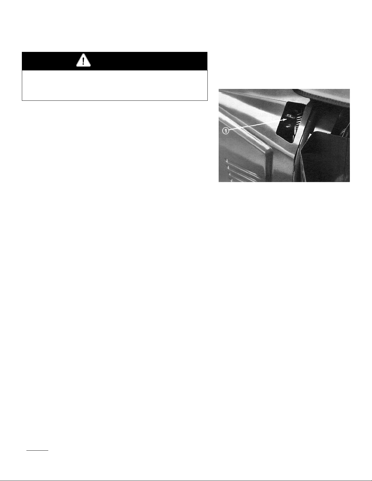
Ignition Switch (Fig.6)—The ignition switch, used to start and
stop the engine, has three positions: OFF, RUN and START. Turn
the key clockwise—START position—to engage the starter motor.
Release the key when the engine starts. The key will move automatically to the ON position. To shut the engine off, turn the key
counterclockwise to the OFF position.
Choke Control (Fig. 6)—To start a cold engine, close the carburetor choke by pulling the choke control out to the ON position.
After the engine starts, regulate the choke to keep the engine running smoothly. As soon as possible, open the choke by pushing it
downward to the OFF position. A warm engine requires little or no
choking.
Throttle Control (Fig. 6) —Lever connects to and operates the
throttle linkage to the carburetor. The trottle control has two posi-
1
2
Figure 5
1. Forward
2. Reverse
Figure 6
1. Fuel tank cap
2. Choke control
3. Throttle control
4. Hour meter
5. Ammeter
6. Fues
11
Page 12
tions: SLOW and FAST. Engine speed can be varied between the
two settings.
Note: The engine cannot be stopped by the throttle control.
Hour Meter (Fig. 6)—Shows the total hours of machine opera-
tion. The Hour Meter starts to function whenever the key switch
is turned to the “ON” position.
Ammeter (Fig. 6)—The ammeter indicates the rate of battery
charge or discharge.
Note: During normal operation, there will usually be slight ammeter needle movement to the positive side.
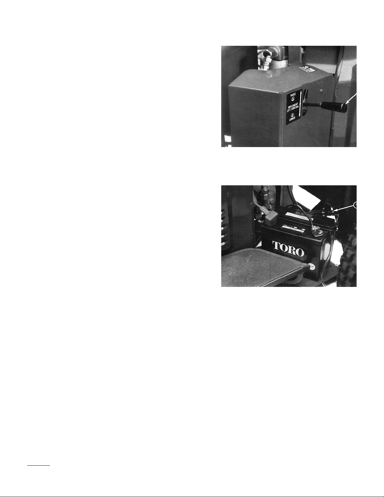
Lift Lever (Fig.7)—To raise the implement, pull the lever up; to
lower the implement, push the lever down. When the desired position is attained, release the lever and it will return to neutral.
NOTE: The SAND PRO has a double-acting lift cylinder. Down
pressure can be applied to the implement for certain operating
conditions.
Fuel Shut-Off Valve (Fig. 8)— Close the fuel shut-off valve when
storing the machine.
1. Lift lever
Figure 7
Figure 8
1. Fuel shut-off valve
12
Page 13

Operating
STARTING/STOPPING THE ENGINE
1. Remove your foot from the traction pedal and make sure the
pedal is in the neutral position.
2. Pull the choke lever out to the ON position—when starting a
cold engine—and the throttle lever to the SLOW position.
3. Insert the key into the ignition switch and rotate it clockwise to
start the engine. Release the key when the engine starts.
Regulate the choke to keep the engine running smoothly.
IMPORTANT: To prevent overheating of the starter
motor, do not engage starter longer than 10 seconds. After
10 seconds of continuous cranking, wait 60 seconds before
engaging starter motor again.
4. When the engine is started for the first time, or after overhaul
of the engine, operate the machine in forward and reverse for
one to two minutes. Also operate the lift lever to be sure of
proper operation of all parts.
CAUTION
Shut off the engine and wait for all moving parts to stop
before checking for oil leaks, loose parts and other malfunctions.
5. To stop the engine, move the throttle control to the SLOW
position and turn the ignition key to OFF. Remove the key
from from the switch to prevent accidental starting.
6. Close the fuel shut-off valve before storing the machine.
CHECK INTERLOCK SYSTEM
OPERATION
The purpose of the interlock system is to prevent the engine from
cranking or starting unless the traction pedal is in “NEUTRAL”.
1. Check interlock operation in a wide open area free of debris
and bystanders. Stop the engine.
2. Sit on the seat. Depress the traction pedal in the forward and
reverse directions, while trying to start the engine. If the engine
13
Page 14
cranks there may be a malfunction in the interlock system.
Repair the system immediately. If the engine does not crank,
system is operating correctly.
CAUTION
The interlock switch is for the operator’s protection, so do
not disconnect it. Check operation of the switch daily to
assure the interlock system is operating. If the switch is
defective, re;place it before operating. Regardless of whether
the switch is operating correctly, replace it every two years to
assure maximum safety. Do not rely entirely on safety
switches—use common sense.
TOWING THE SAND PRO (Fig. 9)
In case of emergency, the SAND PRO can be towed for a short distance. However, Toro does not recommend this as a standard procedure.
IMPORTANT: Do not tow the machine faster than 3–5 kmh
because drive system may be damaged. If the machine must be
moved a considerable distance, transport it on a truck or trailer.
1. Reach under the front of the machine and rotate by-pass valve
on the pump counterclockwise until it is fully open.
2. Before starting the engine, close the by-pass valve securely by
rotating it clockwise. Do not exceed 6–10 Nm torque. Do not
start the engine when the valve is open.
BREAK-IN PERIOD
1. Only 8 hours operating time is required for SAND PRO break-
in period.
2. Since the first hours of operation are critical to future depend-
ability of the machine, monitor its functions and performance
closely so that minor difficulties that could lead to major problems are noted and can be corrected. Inspect the SAND PRO
frequently during break-in for signs of oil leakage, loose fasteners, or any other malfunction.
1. By-pass valve
Figure 9
OPERATING CHARACTERISTICS
Practice driving the SAND PRO because its operating characteristics are different from those of other utility vehicles. Two points to
14
Page 15

consider when operating the vehicle are transmission and engine
speed.
To maintain somewhat constant engine rpm, depress the traction
pedal slowly. This allows the engine to keep up with ground speed
of the vehicle. By contrast, pushing down quickly on the traction
pedal will reduce engine rpm and, as a result, there will not be
enough torque power to move the vehicle. Therefore, to transfer
maximum power to the rear wheels, move the throttle to FAST and
slightly depress the traction pedal.
By comparison, maximum ground speed with no load results when
throttle is at FAST and the traction pedal is slowly but fully
depressed. In summary, always keep engine rpm high enough to
deliver maximum torque power to the rear wheels.
CAUTION
Using the machine demands attention. To prevent tipping or loss
of control, use care when entering and leaving sand traps. Use
extreme caution around ditches, creeks or other hazards. Use caution when operating the machine on a steep slope. Reduce speed
when making sharp turns or when turning on hillsides. Avoid sudden stops and starts. Do not go from reverse to full forward without first coming to a complete stop.
INSPECTION AND CLEAN-UP
At the completion of operation, thoroughly wash the machine with a
garden hose —without a nozzle—so excessive water pressure will
not cause contamination and damage to seals and bearings.
Make sure cooling fins and the area around the engine cooling air
intake are kept free of debris. After cleaning, inspect the machine
for possible hydraulic fluid leaks, damage or wear to hydraulic and
mechanical components.
15
Page 16

Maintenance
LUBRICATION (Fig. 10)
The steering shaft grease fitting must be lubricated regularly with
No. 2 General Purpose Lithium Base Grease.
1. Remove the (5) screws securing the front panel to the frame
(Fig. 10). Locate grease fitting through the opening in the
frame.
NOTE: We do not recommend lubricating the steering chain
unless it becomes stiff because of rust. If the chain rusts, it may
be lubricated lightly with a DRY-TYPE LUBRICANT.
CHANGING CRANKCASE OIL
For new engines, change the oil after the first 5 operating hours.
Thereafter, under normal conditions, change the oil after every 25
hours of engine operation. However, an engine operated in dusty or
dirty conditions requires more frequent oil changes. If possible, run
the engine just before changing oil. Warm oil flows more freely and
carries more contaminants than cold oil.
1. Front Panel
Figure 10
1. Place an oil drain pan below the drain plug on bottom of
crankcase. Clean the area around drain plug.
2. Remove the drain plug and allow oil to flow into drain pan. After
the oil is drained, reinstall the oil drain plug.
3. Remove the dipstick/filler cap and pour approximately 2.5 l of
oil having the APl “service classification” SF into the filler neck.
Oil viscosity is selected according to anticipated ambient temperature. Temperature/viscosity recommendations are:
A. Above 32° F (0°C)—Use SAE 30. The use of multi-weight
oil above 32° F (0°C) is not recommended due to increased
oil consumption an excessive combustion chamber deposits.
B. Below 32° F (0° C)—Use SAE 5W-20 or 5W-30, and if
they are not available, 10W-30 or 10W-40 are acceptable
substitutes.
4. Check the oil and make sure the level is up to the FULL mark on
the dipstick. Add more oil if the level is low; however, DO NOT
OVERFILL.
5. Dispose of oil properly.
16
Page 17

SERVICING AIR CLEANER (Fig. 11–12)
The foam precleaner must be cleaned and re-oiled after every 25
hours engine operation if the engine is operated in clean air conditions. However, the air cleaner must be cleaned every few hours if
operating conditions are extremely dusty or sandy.
1. Remove the engine shield mounting screws and remove the
shield.
2. Remove the lock nut and air cleaner cover.
3. Remove the foam precleaner by sliding it off the paper ele-
ment.
4. A. Wash the foam precleaner in detergent and warm water.
B. Wrap the foam precleaner in cloth and squeeze it dry. Do
not wring the precleaner.
C. Saturate the foam pre-cleaner in engine oil. Squeeze to
remove excess oil.
5. Reinstall it on the paper cartridge.
Inspect the paper element every 50 hours of operation and
replace when dirty or damaged. Do not wash the paper element
or do not clean it with compressed air because damage will
occur.
Note: With the air cleaner disassembled, check the air
cleaner components for damage. Replace if necessary. Make
sure the rubber breather tube in the base plate is securely in
place or severe engine damage may occur.
6. Reinstall the element with the precleaner, element cover seal,
air cleaner element cover, nut, air cleaner cover and lock nut.
1. Air cleaner cover
Figure 11
Figure 12
1. Foam precleaner
7. Tighten the lock nut 1/2 to 1 turn after the nut contacts cover.
Do not overtighten.
8. Reinstall the engine shield.
CHECKING AND REPLACING THE
SPARK PLUG (Fig. 13)
Since the air gap between center and side electrodes increases gradually during normal engine operation, check the condition of electrodes at 100-hour intervals. The correct spark plug for the engine is
1. Main fuel screw
Figure 13
2. Idle fuel adjusting screw
3. Idle speed screw
17
Page 18

Champion RJ-19 LM or equivalent. Set the air gap at .025 in.
1. Remove the engine shield mounting screws and remove the
shield.
2. Clean the area around the spark plug so dirt does not fall into
the cylinder when the plug is removed.
3. Pull the wire off the spark plug and remove the plug from the
cylinder head.
4. Check the condition of the center and side electrodes to deter-
mine operating temperature of the engine.
A. A light-brown insulator tip indicates correct spark plug
and heat range.
B. A black or oily insulator tip indicates an excessively rich
fuel mixture, possibly caused by a dirty air cleaner element or a carburetor that is set too rich.
C. A ight-gray or blistered-white insulator indicates overheat-
ing caused by a lean carburetor setting or and incorrect
spark plug (heat range too high).
IMPORTANT: A cracked, fouled or dirty spark plug must
be replaced. Do not sandblast, scrape or clean electrodes by
using a wire brush because grit may release from the plug
and enter combustion chamber resulting in engine damage.
5. After setting the air gap at .025”, install the spark plug in the
cylinder head. Tighten the plug to 13-20 Nm. Push the wire
onto the spark plug.
6. Reinstall the engine shield.
CLEANING THE CYLINDER HEAD FINS
To avoid overheating and possible engine damage, cooling fins on
the cylinder head must be kept clean.
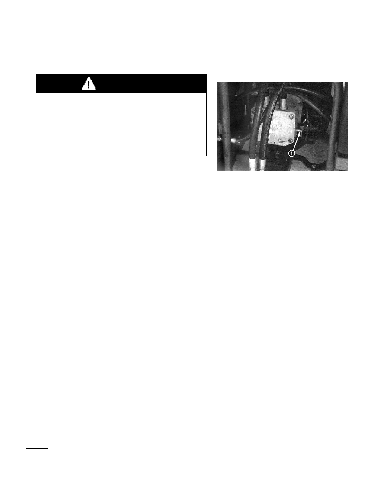
CHANGING HYDRAULIC SYSTEM OIL
AND FILTER (Fig. 14)
1. Hydraulic filter
Figure 14
The hydraulic system filter must be changed initially, after the first
ten hours of operation, and thereafter every 500 hours of operation
or yearly, whichever comes first. Use a genuine Toro oil filter for
replacement. The hydraulic oil must be changed every 500 hours of
operation or yearly, whichever comes first.
18
Page 19

1. Park the machine on a level surface and turn the engine off.
2. Pivot seat upward.
3. Disconnect hose from bottom fitting of the reservoir and let oil
flow into drain pan. Reinstall and tighten the hose when the oil
stops draining.
4. Clean the area around the hydraulic oil filter. Remove the filter
from the bottom of the filter housing and allow the oil to flow
into a drain pan. Use a bottom-type filter wrench. Dispose of
the oil filter properly.
5. Apply a film of oil on the filter gasket. Install the filter by hand
until the gasket contacts mounting head; then tighten filter an
additional three-fourth’s turn.
6. Fill the reservoir to proper level, refer to Check Hydraulic
System.
7.
Place all controls in the neutral or disengaged position and start
the engine. Run the engine at its lowest possible RPM to purge
the system of air.
8. Run the engine until the lift cylinder extends and retracts and
forward and reverse wheel motion is achieved.
9. Stop the engine and check the oil level in the reservoir, add oil
if necessary.
10. Check all connections for leaks.
11. Lower the seat.
12. Dispose of oil properly.
CHECKING HYDRAULIC LINES AND
HOSES
After every 100 operating hours, check hydraulic lines and hoses for
leaks, kinked lines, loose mounting supports, wear, loose fittings,
weather deterioration and chemical deterioration. Make all necessary repairs before operating.
19
Page 20

WARNING
Keep body and hands away from pin hole leaks or nozzels that
eject high-pressure hydraulic fluid. Use cardboard or paper to find
hydraulic leaks. Hydraulic fluid escaping under pressure can penetrate skin and cause injury. Fluid accidentally injected into the
skin must be surgically removed within a few hours by a doctor
familiar with this form of injury or gangrene may result.
REPLACING THE FUEL FILTER (Fig. 15)
An in-line filter is incorporated into the fuel line. Use the following
procedures should replacement become necessary:
1. Close the fuel shut-off valve.
2. Clamp both fuel lines that connect to the fuel filter so gasoline
cannot drain when lines are removed.
3. Loosen the hose clamps at both ends of the filter and pull the
fuel lines off the filter.
4. Slide hose clamps onto the ends of the fuel lines. Push the fuel
lines onto the fuel filter and secure them with hose clamps. Be
sure the arrow on side of filter points toward the carburetor.
BATTERY STORAGE
If the machine will be stored for more than 30 days, remove the battery and charge it fully. Either store it on the shelf on the machine.
Leave the cables disconnected if stored on the machine. Store the
battery in a cool atmosphere to avoid quick deterioration of the
charge in the battery. To prevent the battery from freezing, make
sure it is fully charged. The specific gravity of a fully charged battery is 1.250.
1. Fuel filter
Figure 15
2. Hose clamps
BATTERY CARE
1. Battery electrolyte level must be properly maintained and the
top of the battery kept clean. lf the machine is stored in a location where temperatures are extremely high, the battery will
run down more rapidly than if the machine is stored in a location where temperatures are cool.
2. Keep the top of battery clean by washing periodically with a
20
Page 21

brush dipped in ammonia or bicarbonate of soda solution.
Flush the top surface with water after cleaning. Do not remove
the fill cap while cleaning.
3. Battery cables must be tight on terminals to provide good elec-
trical contact.
4. If corrosion occurs at the terminals, disconnect the cables, neg-
ative (–) cable first and scrape clamps and terminals separately.
Reconnect cables, positive (+) cable first and coat terminals
with petroleum jelly.
5. Check the electrolyte level every 25 operating hours or, if the
machine is in storage, every 30 days.
6. Maintain cell level with distilled or demineralized water. Do
not fill cells above the fill line.
IDENTIFICA TION AND ORDERING
MODEL AND SERIAL NUMBERS
The SAND PRO 2000 has two identification numbers: a model
number and a serial number. These numbers are stamped into a
plate located on left fender. In any correspondence concerning the
unit, supply the model and serial numbers to ensure correct information and replacement parts are obtained.
Note: Do not order by reference number if a parts catalog is being
used; use the part number.
To order replacement parts from an authorized TORO Distributor,
supply the following information:
1. Model and serial numbers.
2. Part number, description, and quantity of parts desired.
21
Page 22

Page 23

Page 24

 Loading...