

Page 1
FormNo.3391-391RevB
FrontLiftFrame
SandPro
ModelNo.08712—SerialNo.311000336andUp
®
/IneldPro
Proposition65Warning
ThisproductcontainsachemicalorchemicalsknowntotheStateofCalifornia
tocausecancer,birthdefects,orreproductiveharm.
ThisproductcomplieswithallrelevantEuropeandirectives.Fordetails,pleaseseetheDeclarationof
Incorporation(DOI)atthebackofthispublication.
Note:Determinetheleftandrightsidesofthemachinefromthenormaloperatingposition.
®
5040TractionUnit
WARNING
CALIFORNIA
Operator'sManual
Setup
LooseParts
Usethechartbelowtoverifythatallpartshavebeenshipped.
ProcedureDescription
1
2
3
4
Nopartsrequired
Nopartsrequired
StraighthydraulicttingwithO-ring
90-degreehydraulicttingwithO-ring
Liftvalve
Valveplate1
Bolt(1/4x3inches)
Locknut(1/4inch)
Bolt(#10x1-1/4inches)
Locknut(#10)
Liftlever
Rightplowplate1
Leftplowplate
Bolt(1/2x2inches)
Locknut(1/2inch)
Hitchframebracket
Bolt(1/2x1-3/4inches)
Qty.
Use
–
–
2
2
1
3
3
2
2
1
1
4
4
1
2
Preparethemachine.
Removetheshrouds.
Installtheliftvalve.
Installtheplowplates.
©2017—TheT oro®Company
8111LyndaleAvenueSouth
Bloomington,MN55420
Registeratwww.T oro.com.
OriginalInstructions(EN)
PrintedintheUSA
AllRightsReserved
*3391-391*B
Page 2

ProcedureDescription
5
6
7
8
9
Hitchframe
Bolt(3/8x2inches)
Nut(3/8inch)
Capscrew(3/8x1-1/2inches)
Locknut(3/8inch)
Cylinderpin
Adapterplate1
Pusharmtube1
Pinassembly2
Thread-formingscrew
Bolt(5/8x1-1/2inches)
Washer(1.68-inchoutsidediameterx
0.65-inchinsidediameter)
Tube1
Clevispin
Cotterpin
45-degreehydraulicttingwithO-ring
Hydrauliccylinder1
90-degreehydraulicttingwithO-ring
Smallretainingring
Pin1
Largeretainingring2
Tubeassembly1
Hydraulichose(PartNo.108-8449)
Hydraulichose(PartNo.108-8453)
Hydraulichose(PartNo.108-8454)
Wirehoseholder1
Threadformingscrew(5/16x3/4inch)
Plasticcabletie3
Leverguideplate1
Flange-headscrew2
Washer2
Controlpaneldecal
Controlpanel
Knob1
Plasticcabletie3
Operator’sManual
Qty.
Use
1
2
2
2
2
2
Installthepusharmsandhitchframe.
2
2
2
1
1
1
1
1
1
1
1
2
1
1
1
Installthehydrauliccylinder.
Installthehydraulichoses.
Installthecontrolpanelandleverguide
plate.
Readthedocumentationandstoreitin
asafelocation.
2
Page 3
1
PreparingtheMachine
NoPartsRequired
Procedure
1.Parkthemachineonalevelsurface.
2.Lowertheattachments.
3.Engagetheparkingbrake.
4.Shutofftheengineandremovethekey .
2
RemovingtheShrouds
NoPartsRequired
Procedure
1.Jackuptherearofthemachineandposition
blocksundertherearwheelmotormounts.
2.Removetherightreartire.
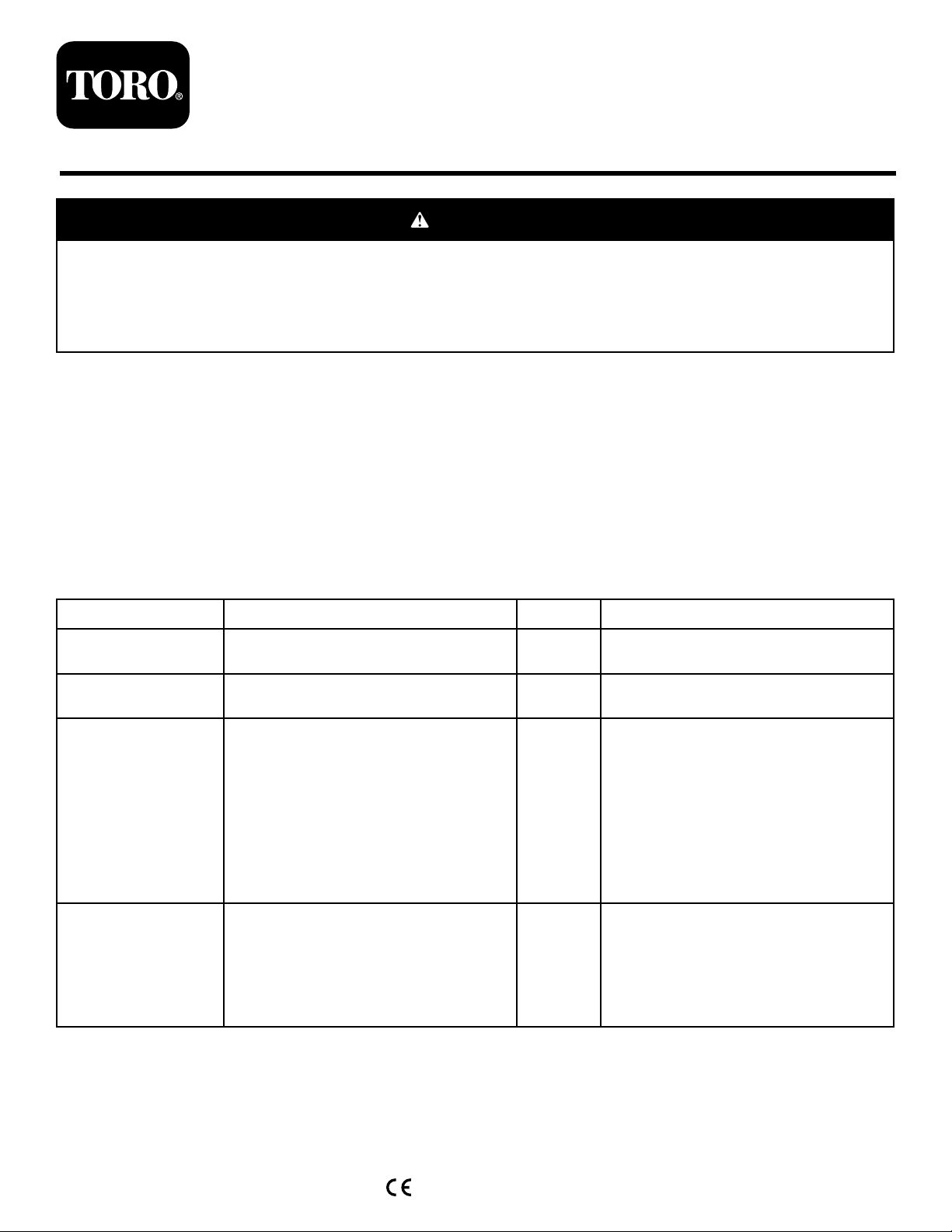
3.Removethe4washersandboltsmountingthe
controlpaneltotheconsole(Figure1).
4.Unplugthewirefromthehourmeter.
5.Removethecontrolpanel(Figure1).
6.Removethe3boltssecuringtheconsoletothe
frame(Figure1).Removetheconsolebygently
liftingthebottomedgeoftheconsolearound
thesupportbracketandslidingitupbeyondthe
brakehandle.
g003660
Figure1
1.Controlpanel3.Consolemountingbolt
locations
2.Console
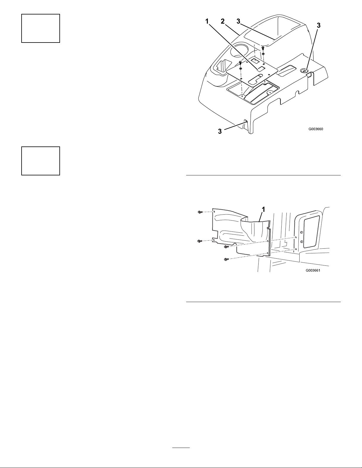
7.Removethe4boltssecuringtherighthand
wheelshroudtotheframeandremovethe
shroud(Figure2).
g003661
Figure2
1.Righthandwheelshroud
8.Disconnectandremovethecentershroudfrom
theframe(Figure3).
3
Page 4

Figure4
1.Straighttting3.Liftvalve
2.90-degreetting
g003663
Figure3
1.Centershroud
3
InstallingtheLiftValve
Partsneededforthisprocedure:
2
StraighthydraulicttingwithO-ring
2
90-degreehydraulicttingwithO-ring
1
Liftvalve
1Valveplate
3
Bolt(1/4x3inches)
3
Locknut(1/4inch)
2
Bolt(#10x1-1/4inches)
2
Locknut(#10)
1
Liftlever
g003662
2.Mountthevalveassembly,pivotbracket,and
valveplatetotheframewith3bolts(1/4x3
inches)and3locknuts(Figure5).Positionthe
valveplateagainstthefrontoftheframemember
whenmounting,andtorquethefastenersto10
to12N∙m(90to110in-lb).
Note:Thevalveinstallationisverysimilarto
thevalvecurrentlyinstalled.
3.Looselymountthepivotleverassemblytothe
valvespoolandtotheoffsetlinkwith2bolts
(#10x1-1/4inch)and2locknuts(Figure5).
Note:Donottightenthefastenersatthistime.
Procedure
1.Threadthe2ttings(90-degree)andthe2
straighthydraulicttingsintothenewliftvalve.
Note:PositionthettingsasshowninFigure
4.Donottightenthe90-degreettingsatthis
time.MakesurethatallO-ringsarelubricated
andproperlypositionedonthettingsbefore
installation.
4
Page 5
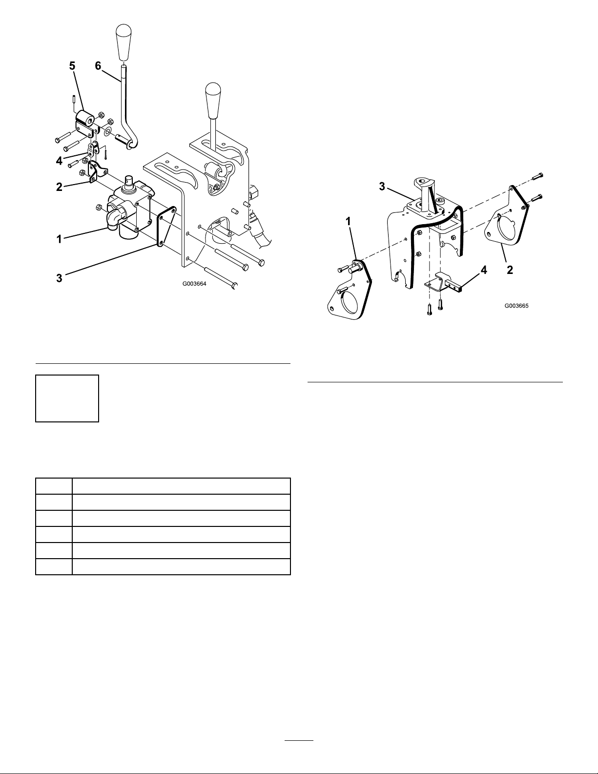
Figure5
4.Removeanddiscardthe2boltssecuringthe
frontofthesteeringpivottothetopofthecaster
fork(Figure6).
5.Usingthecasterforkandsteeringpivotmounting
holes,mountthehitchframebrackettothe
undersideofthecasterforkwith2bolts(1/2x
1-3/4inches);refertoFigure6.
Note:Itmayberequiredtopartiallydeate
thetiretogainclearance.Thewheelmotor
hydraulichoseshouldnotrestontopofthehitch
framebracket.
g003664
1.Valveassembly
2.Pivotbracket5.Pivot
3.Valveplate6.Lever
4.Offsetlink
4
InstallingthePlowPlates
Partsneededforthisprocedure:
1Rightplowplate
1
Leftplowplate
4
Bolt(1/2x2inches)
4
Locknut(1/2inch)
1
Hitchframebracket
2
Bolt(1/2x1-3/4inches)
Procedure
1.Looselymounttherighthandplowplatetothe
rightsideofthecasterforkwith2bolts(1/2x2
inches)andlocknutsasshowninFigure6.
Figure6
1.Rightplowplate
2.Leftplowplate4.Hitchframebracket
3.Steeringpivot
g003665
Note:Donottightenthefastenersyet.
2.Repeattheprocedurewiththelefthandplow
plate(Figure6).
3.Jackupthefrontofthemachineuntilthefront
wheelisofftheoor.
5
Page 6
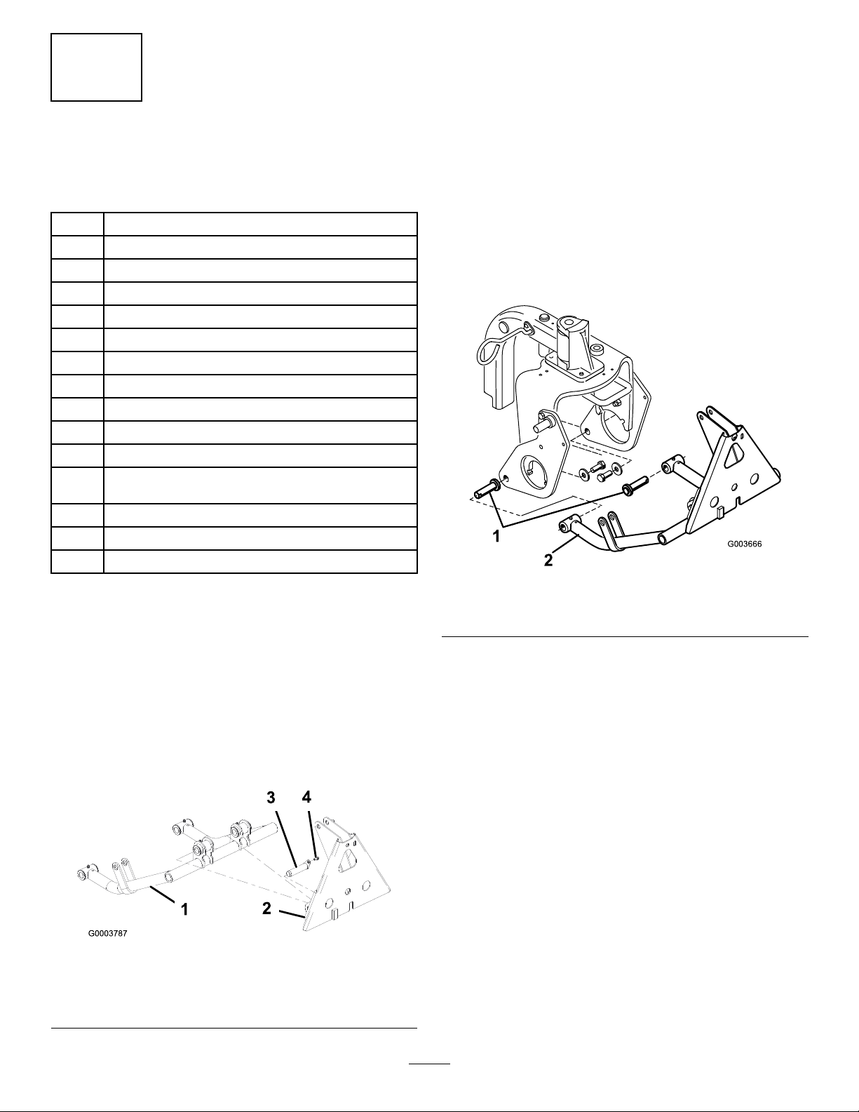
3.Insertacylinderpinintoeachpusharmtubeas
showninFigure8.
5
InstallingthePushArms
andHitchFrame
Partsneededforthisprocedure:
1
Hitchframe
2
Bolt(3/8x2inches)
2
Nut(3/8inch)
2
Capscrew(3/8x1-1/2inches)
2
Locknut(3/8inch)
2
Cylinderpin
1Adapterplate
1Pusharmtube
2Pinassembly
2
Thread-formingscrew
2
Bolt(5/8x1-1/2inches)
Washer(1.68-inchoutsidediameterx0.65-inchinside
2
diameter)
1Tube
1
Clevispin
1
Cotterpin
4.Insertthepusharmtubesontotherightandleft
plowplatesaligningthecylinderpinguideswith
theholesintheplowplates(Figure8).
Note:Ifunabletogetthepusharmtubes
aroundtheplowplates,loosenthenutssecuring
theplowplatestothecasterfork.
5.Mounteachcylinderpintoeachplowplate
withabolt(5/8x1-1/2inches)andawasher
(1.68-inchoutsidediameterx0.65-inchinside
diameter)asshowninFigure8.
Note:T orquetheboltsto203N-m(150ft-lb).
g003666
Figure8
Procedure
1.Lowerthemachinesothatthefrontwheelison
theoor.
2.Securethepusharmtubetotheadapter
platewith2pinassembliesandsecurethe
pinassembliestotheadapterplateswith2
thread-formingscrews.
Note:Positionthecomponentsasshownin
Figure7.
Figure7
1.Pusharmtube3.Pinassembly
2.Adapterplate
4.Thread-formingscrew
1.Cylinderpin
2.Pusharmtube
6.Mountthetopofthehitchframetothehitch
framebracketwith2bolts(3/8x2inches)and
nuts(Figure9).
7.Mountthehitchframetubestotheplowplates
withbolts(3/8x1-1/2inches)andnuts(Figure
9),andtightenthefasteners.
g003787
6
Page 7

Figure9
1.Hitchframebracket3.Hitchframetube
2.Hitchframe
8.Securetheframeadaptertothehitchframewith
atube,aclevispin,andacotterpin(Figure10).
g028340
Figure11
Important:Ensurethattheexistinghoses
areroutedabovetheguide,asshownin
Figure11.
g018349
6
InstallingtheHydraulic Cylinder
Partsneededforthisprocedure:
1
45-degreehydraulicttingwithO-ring
1Hydrauliccylinder
1
90-degreehydraulicttingwithO-ring
1
Smallretainingring
1Pin
2Largeretainingring
1.Frameadapter
2.Tube
Figure10
3.Clevispinwithgrease
tting
Procedure
1.Threada90-degreettingintotheupperport
inthehydrauliccylinder.Positionthettingas
showninFigure12.
g018307
7
Note:MakesurethatallO-ringsarelubricated
andproperlypositionedonttingsbefore
installation.
Note:T opreventcontaminationtothehydraulic
ttingsorhoses,donotremovethecapsfrom
thettingsorhosesuntiltheyareinstalled.
2.Threada45-degreettingintothelowerport
inthehydrauliccylinder.Positionthettingas
showninFigure12.
Page 8
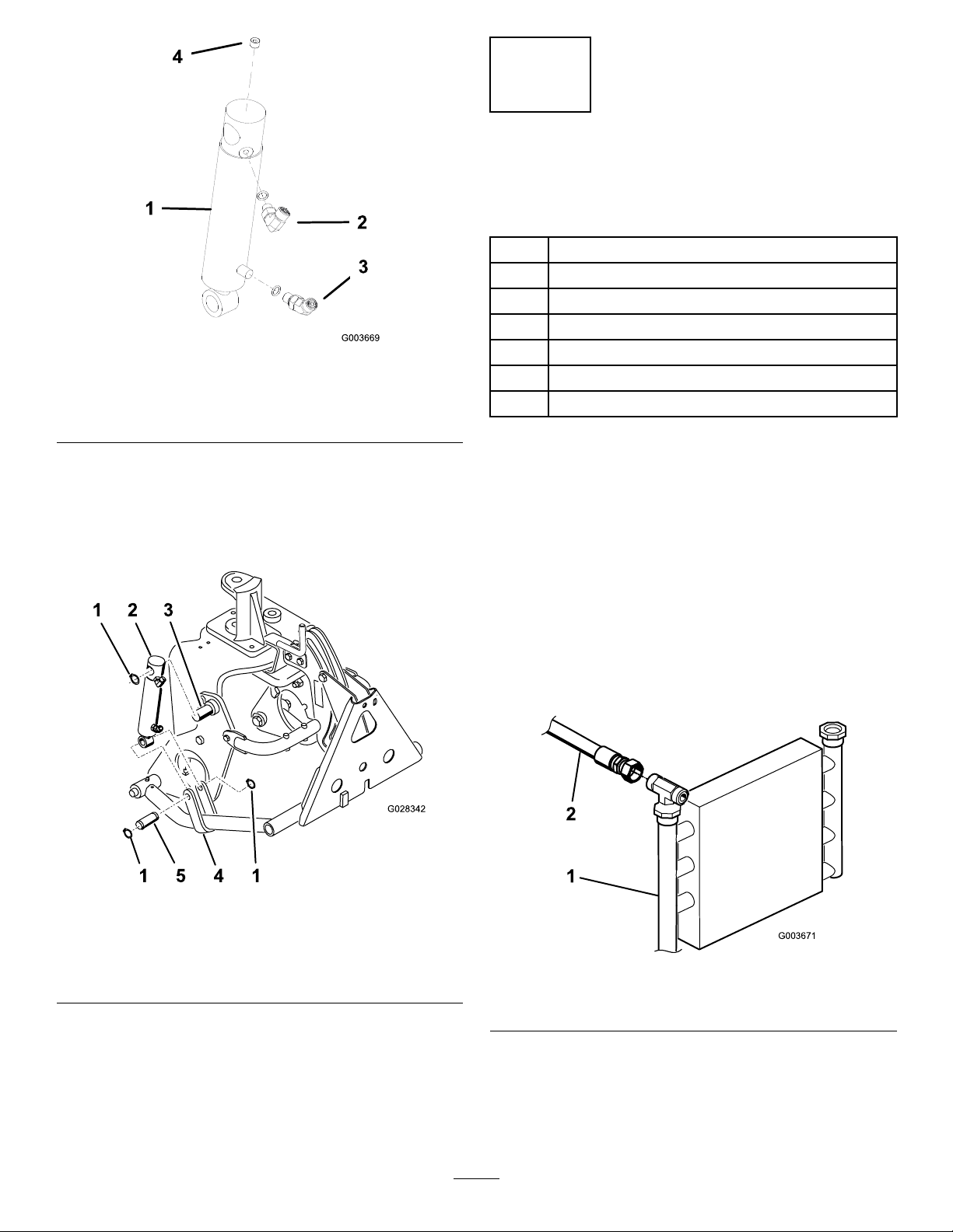
Figure12
1.Hydrauliccylinder
2.90-degreetting4.Plug(1/8inch)
3.45-degreetting
7
InstallingtheHydraulic Hoses
Partsneededforthisprocedure:
1Tubeassembly
1
Hydraulichose(PartNo.108-8449)
1
Hydraulichose(PartNo.108-8453)
1
Hydraulichose(PartNo.108-8454)
g003669
1Wirehoseholder
2
Threadformingscrew(5/16x3/4inch)
3Plasticcabletie
3.Mountthetopofthehydrauliccylinderbarrel
tothepinontheright-handplowplatewitha
retainingring(Figure13).
Note:Positionthecylinderhydraulicports
forward.
Figure13
Procedure
1.Locatethehydraulictubethatgoesfromtheoil
coolertotheexistingliftvalve(Figure14).
2.Removethefastenersandtubeclampsecuring
thehydraulictubestotheframe.
3.Disconnectandremovethehydraulictubefrom
theoilcoolerandtheliftvalve(Figure14).
Note:Tominimizeoillosswhenremoving
thehydraulictube,havethereplacementhose
readyorcapthettingonthecoolerusingoneof
theprotectiveshippingcapsremovedfromthe
tubeassembly,PartNo.108-8447(Figure15).
g028342
1.Retainingring4.Pusharmstrap
2.Hydrauliccylinder5.Pin
3.Pin(onplowplate)
4.Mountthecylinderrodtothepusharmstraps
withapinand2retainingrings(Figure13).
Figure14
1.Oilcooler
4.Securetheremaininghydraulictubetothe
framewiththeclampandfastenerspreviously
removed
5.Connectthetubeassembly,PartNo.108-8447,
tothe90-degreettingontheleftsideofthe
8
2.Hydraulictube
g003671
Page 9

newvalveandthevacatedttingontheexisting
liftvalve(Figure15).
6.Connectthe45-degreettingendofhydraulic
hose,PartNo.108-8449,tothe90-degreetting
ontherightsideofthevalveandthestraight
endofthehosetothevacantoilcoolertting
(Figure15).RefertoFigure16andFigure17
forhoserouting.
7.Mountthewirehoseholdertotheleftframetube
with2thread-formingscrews(5/16x3/4inch);
refertoFigure15.
8.Connecttheshort90-degreettingendof
hydraulichose,PartNo.108-8453,tothetop
straightttingontherearofthevalve.Routethe
hosethroughthewirehoseholderandconnect
thestraightendofthehosetothetophydraulic
cylindertting(Figure15).RefertoFigure16
andFigure17forhoserouting.
9.Connectthelong90-degreettingendofthe
hydraulichose,PartNo.108-8454,tothebottom
straightttingontherearofthevalve.Routethe
hosethroughthewirehoseholderandconnect
thestraightendofthehosetothebottom
hydrauliccylindertting(Figure15).Referto
Figure16andFigure17forhoserouting.
Important:Makesurethatthehosesare
routedawayfromanysharp,hot,ormoving
components.
10.Tightenallfastenersandttings.
11.Usingcableties,securethehosestothe
machineatthelocationsshowninFigure16and
Figure17.
Figure15
1.Newvalve3.Existingvalve5.Wirehoseholder
2.Tubeassembly(PartNo.
108-8447)
4.Hydraulichose(PartNo.
108-8449)
6.Hydraulichose(PartNo.
108-8453)
g003672
7.Hydraulichose(PartNo.
108-8454)
9
Page 10

Figure16
g218466
1.Cabletie2.Hydraulichose(PartNo.
108-8449)
3.Hydraulichose(PartNo.
108-8453)
4.Hydraulichose(PartNo.
108-8454)
10
Page 11

Figure17
1.Cabletie3.Hydraulichose(PartNo.108-8453)
2.Hydraulichose(PartNo.108-8449)4.Hydraulichose(PartNo.108-8454)
g218467
11
Page 12

8
InstallingtheControlPanel andLeverGuidePlate
Partsneededforthisprocedure:
1Leverguideplate
2Flange-headscrew
2Washer
1
Controlpaneldecal
1
Controlpanel
1Knob
3Plasticcabletie
Procedure
1.Inserttheleverguideplateovertheliftleverand
looselysecureittotheframewith2ange-head
screwsandwashers(Figure18).
WARNING
Hydraulicuidescapingunderpressure
canpenetrateskinandcauseinjury.
•Ifhydraulicuidisinjectedintothe
skinitmustbesurgicallyremoved
withinafewhoursbyadoctorfamiliar
withthistypeofinjury.Gangrenemay
resultifthisisnotdone.
•Keepbodyandhandsawayfrom
pinholeleaksornozzlesthateject
high-pressurehydraulicuid.
•Usecardboardorpapertond
hydraulicleaks.
•Safelyrelieveallpressureinthe
hydraulicsystembeforeperforming
anyworkonthehydraulicsystem.
•Makesurethatallhydraulic-uid
hosesandlinesareingoodcondition
andallhydraulicconnectionsand
ttingsaretightbeforeapplying
pressuretothehydraulicsystem.
3.Startthetractionunitengineandcheckthe
ttingconnections.
4.Installthewheelshroud,thecentershroud,and
theconsole.
Figure18
1.Leverguideplate2.Flange-headscrews
2.Checkthehydraulic-uidlevelandreplenishthe
uidasrequired.
Note:Donotinstallthecontrolpanelatthis
time.Makesurethattheshroudsdotheinterfere
withthehoses.Routethehosesasrequired.
Reversetheshroudinstallationprocedureused
instep1.
5.Installthereartireandremovetheblocksfrom
undertherearofthemachine.
6.Torquethelugsnutsto61to75N∙m(45to55
ft-lb).
g003675
7.WiththeenginerunningandliftleverintheFloat
position,slidetheleverguideplateuntilthelift
cylindercanbeextendedandretractedbyhand
(Figure18).
WARNING
Theenginemustberunningsothatthe
naladjustmentoftheliftleverdetent
platecanbeperformed.Contactwith
movingpartsorhotsurfacesmaycause
personalinjury.
Keephands,feet,face,andotherbody
partsawayfromrotatingparts,the
mufer,andotherhotsurfaces.
8.Tightenbothliftleverguideplatemounting
screwstosecuretheadjustment(Figure18).
12
Page 13

9.Removethehourmeterfromtheoldcontrol
panelandinstallitinthenewcontrolpanel.
10.Installthenewcontrolpanelandplugthewire
intothehourmeter.
11.Securethecontrolpanelinplacewiththe
fastenerspreviouslyremoved(Figure19).
Attachments/Accessories
AselectionofToroapprovedattachmentsand
accessoriesisavailableforusewiththemachineto
enhanceandexpanditscapabilities.Contactyour
AuthorizedServiceDealerorDistributororgoto
www.T oro.comforalistofallapprovedattachments
andaccessories.
OperatingTips
•Thefrontliftframeisdesignedtoacceptonly
certainattachments.Donottrytoinstallarear
mountattachmenttothefrontliftframe,asdamage
tothemachinemayoccur.
•T olowerthefrontliftframe,pushtheliftlever
forward.
•T oallowthefrontliftframetooat,pushthelift
leverforwardandtothesideintothedetent.
Figure19
1.Knob
12.Installtheknobontotheliftlever(Figure19).
13.Greasethefrontliftframe;refertoGreasingthe
LiftFrame(page13).
14.Checkthehydraulic-uidlevelandreplenishthe
uidasrequired.
2.Controlpanel
9
Reading/Storingthe Documentation
Partsneededforthisprocedure:
1
Operator’sManual
g003676
•T oraisethefrontliftframe,pulltheliftlever
rearward.
•Becomefamiliarwiththesafeoperationofthe
equipment,withtheoperatorcontrols,andsafety
signs.
•Keephandsandfeetawayfrommovingpartsand
hotsurfaces.
Maintenance
GreasingtheLiftFrame
Thefrontliftframehas5greasettings(Figure20)
thatmustbelubricatedregularlywithNo.2lithium
grease.Ifthemachineisoperatedundernormal
conditions,lubricateallbearingsandbushingsafter
every100hoursofoperation.Lubricatethebearings
andbushingsimmediatelyaftereverywashing,
regardlessoftheintervallisted.
Procedure
1.Readthedocumentation.
2.Storethedocumentationinasafeplace.
Operation
Specications
Netweight
38.5kg(85lb)
13
Page 14

Figure20
g003677
14
Page 15
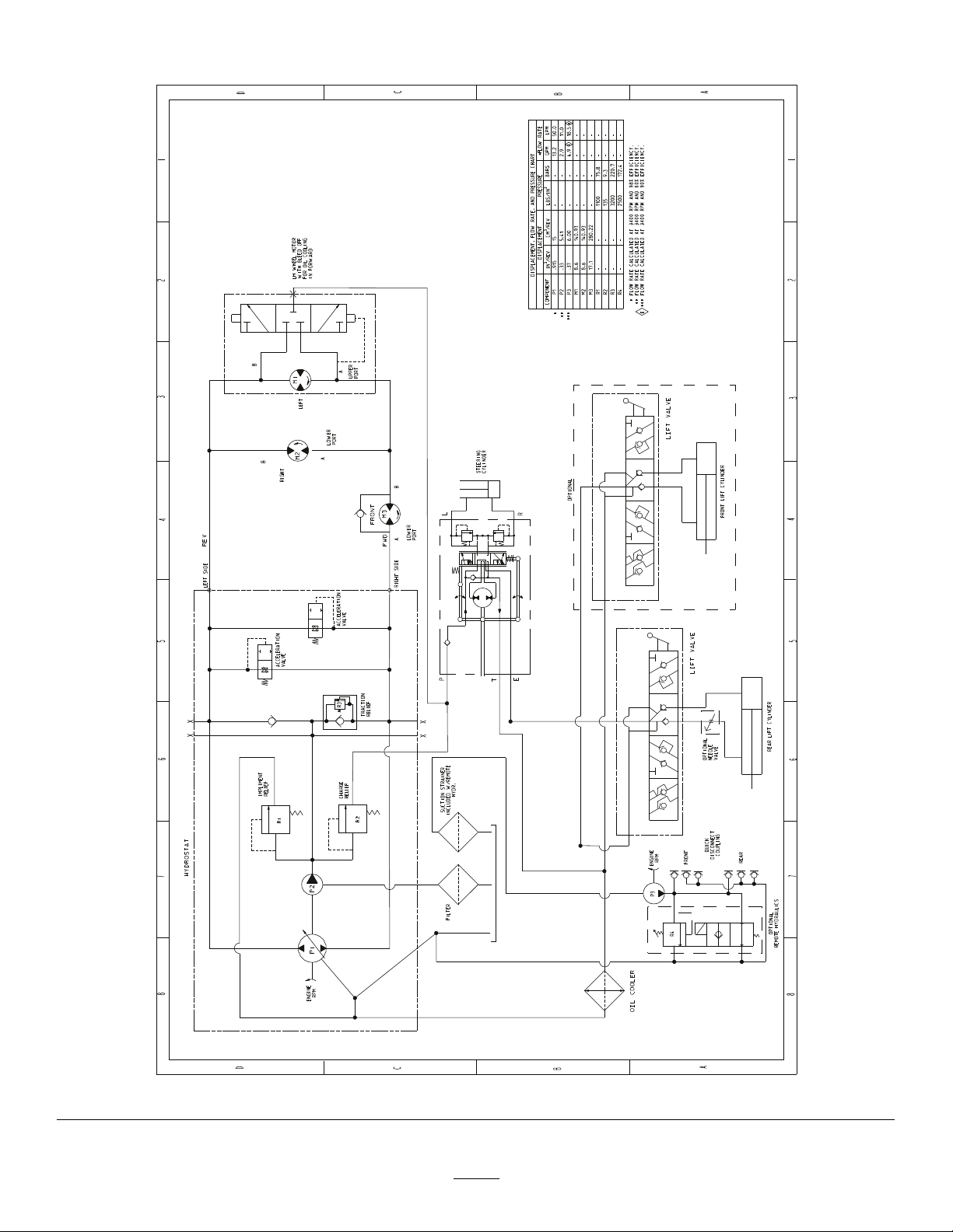
Schematics
Hydraulicschematic108-2946(Rev.E)
15
g218266
Page 16

Notes:
Page 17

Notes:
Page 18

DeclarationofIncorporation
TheToroCompany,8111LyndaleAve.South,Bloomington,MN,USAdeclaresthatthefollowingunit(s)
conform(s)tothedirectiveslisted,wheninstalledinaccordancewiththeaccompanyinginstructionsontocertain
ToromodelsasindicatedontherelevantDeclarationsofConformity .
ModelNo.
SerialNo.
08712
—
ProductDescriptionInvoiceDescription
FrontLiftFrameFRONTLIFTFRAMEKITFrontLiftFrameAssembly2006/42/EC
GeneralDescription
Directive
RelevanttechnicaldocumentationhasbeencompiledasrequiredperPartBofAnnexVIIof2006/42/EC.
Wewillundertaketotransmit,inresponsetorequestsbynationalauthorities,relevantinformationonthispartly
completedmachinery.Themethodoftransmissionshallbeelectronictransmittal.
ThismachineryshallnotbeputintoserviceuntilincorporatedintoapprovedToromodelsasindicatedonthe
associatedDeclarationofConformityandinaccordancewithallinstructions,wherebyitcanbedeclaredin
conformitywithallrelevantDirectives.
Certied:
JohnHeckel
Sr.EngineeringManager
811 1LyndaleAve.South
Bloomington,MN55420,USA
May31,2017
AuthorizedRepresentative:
MarcelDutrieux
ManagerEuropeanProductIntegrity
ToroEuropeNV
Nijverheidsstraat5
2260Oevel
Belgium
Tel.+3216386659
Page 19

EuropeanPrivacyNotice
TheInformationT oroCollects
ToroWarrantyCompany(T oro)respectsyourprivacy .Inordertoprocessyourwarrantyclaimandcontactyouintheeventofaproductrecall,weaskyou
tosharecertainpersonalinformationwithus,eitherdirectlyorthroughyourlocalT orocompanyordealer.
TheTorowarrantysystemishostedonserverslocatedwithintheUnitedStateswhereprivacylawmaynotprovidethesameprotectionasapplies
inyourcountry.
BYSHARINGYOURPERSONALINFORMATIONWITHUS,YOUARECONSENTINGTOTHEPROCESSINGOFYOURPERSONALINFORMATION
ASDESCRIBEDINTHISPRIVACYNOTICE.
TheWayToroUsesInformation
Toromayuseyourpersonalinformationtoprocesswarrantyclaims,tocontactyouintheeventofaproductrecallandforanyotherpurposewhichwetell
youabout.ToromayshareyourinformationwithToro'safliates,dealersorotherbusinesspartnersinconnectionwithanyoftheseactivities.Wewillnot
sellyourpersonalinformationtoanyothercompany.Wereservetherighttodisclosepersonalinformationinordertocomplywithapplicablelawsand
withrequestsbytheappropriateauthorities,tooperateoursystemsproperlyorforourownprotectionorthatofotherusers.
RetentionofyourPersonalInformation
Wewillkeepyourpersonalinformationaslongasweneeditforthepurposesforwhichitwasoriginallycollectedorforotherlegitimatepurposes
(suchasregulatorycompliance),orasrequiredbyapplicablelaw.
Toro'sCommitmenttoSecurityofY ourPersonalInformation
Wetakereasonableprecautionsinordertoprotectthesecurityofyourpersonalinformation.Wealsotakestepstomaintaintheaccuracyandcurrent
statusofpersonalinformation.
AccessandCorrectionofyourPersonalInformation
Ifyouwouldliketorevieworcorrectyourpersonalinformation,pleasecontactusbyemailatlegal@toro.com.
AustralianConsumerLaw
AustraliancustomerswillnddetailsrelatingtotheAustralianConsumerLaweitherinsidetheboxoratyourlocalT oroDealer.
374-0282RevC
Page 20

ToroGeneralCommercialProductWarranty
ATwo-YearLimitedWarranty
ConditionsandProductsCovered
TheT oroCompanyanditsafliate,T oroWarrantyCompany,pursuant
toanagreementbetweenthem,jointlywarrantyourToroCommercial
product(“Product”)tobefreefromdefectsinmaterialsorworkmanship
fortwoyearsor1500operationalhours*,whicheveroccursrst.This
warrantyisapplicabletoallproductswiththeexceptionofAerators
(refertoseparatewarrantystatementsfortheseproducts).Wherea
warrantableconditionexists,wewillrepairtheProductatnocosttoyou
includingdiagnostics,labor,parts,andtransportation.Thiswarranty
beginsonthedatetheProductisdeliveredtotheoriginalretailpurchaser.
*Productequippedwithanhourmeter.
InstructionsforObtainingWarrantyService
YouareresponsiblefornotifyingtheCommercialProductsDistributoror
AuthorizedCommercialProductsDealerfromwhomyoupurchasedthe
Productassoonasyoubelieveawarrantableconditionexists.Ifyouneed
helplocatingaCommercialProductsDistributororAuthorizedDealer,or
ifyouhavequestionsregardingyourwarrantyrightsorresponsibilities,
youmaycontactusat:
ToroCommercialProductsServiceDepartment
ToroW arrantyCompany
811 1LyndaleAvenueSouth
Bloomington,MN55420-1196
952–888–8801or800–952–2740
E-mail:commercial.warranty@toro.com
OwnerResponsibilities
AstheProductowner,youareresponsibleforrequiredmaintenanceand
adjustmentsstatedinyourOperator'sManual.Failuretoperformrequired
maintenanceandadjustmentscanbegroundsfordisallowingawarranty
claim.
ItemsandConditionsNotCovered
Notallproductfailuresormalfunctionsthatoccurduringthewarranty
periodaredefectsinmaterialsorworkmanship.Thiswarrantydoesnot
coverthefollowing:
•Productfailureswhichresultfromtheuseofnon-Tororeplacement
parts,orfrominstallationanduseofadd-on,ormodiednon-T oro
brandedaccessoriesandproducts.Aseparatewarrantymaybe
providedbythemanufactureroftheseitems.
•Productfailureswhichresultfromfailuretoperformrecommended
maintenanceand/oradjustments.Failuretoproperlymaintainyour
ToroproductpertheRecommendedMaintenancelistedinthe
Operator’sManualcanresultinclaimsforwarrantybeingdenied.
•ProductfailureswhichresultfromoperatingtheProductinanabusive,
negligent,orrecklessmanner.
•Partssubjecttoconsumptionthroughuseunlessfoundtobedefective.
Examplesofpartswhichareconsumed,orusedup,duringnormal
Productoperationinclude,butarenotlimitedto,brakepadsand
linings,clutchlinings,blades,reels,rollersandbearings(sealedor
greasable),bedknives,sparkplugs,castorwheelsandbearings,tires,
lters,belts,andcertainsprayercomponentssuchasdiaphragms,
nozzles,andcheckvalves,etc.
•Failurescausedbyoutsideinuence.Conditionsconsideredtobe
outsideinuenceinclude,butarenotlimitedto,weather ,storage
practices,contamination,useofunapprovedfuels,coolants,lubricants,
additives,fertilizers,water,orchemicals,etc.
•Failureorperformanceissuesduetotheuseoffuels(e.g.gasoline,
diesel,orbiodiesel)thatdonotconformtotheirrespectiveindustry
standards.
•Normalnoise,vibration,wearandtear,anddeterioration.
•Normal“wearandtear”includes,butisnotlimitedto,damagetoseats
duetowearorabrasion,wornpaintedsurfaces,scratcheddecalsor
windows,etc.
Parts
Partsscheduledforreplacementasrequiredmaintenancearewarranted
fortheperiodoftimeuptothescheduledreplacementtimeforthatpart.
Partsreplacedunderthiswarrantyarecoveredforthedurationofthe
originalproductwarrantyandbecomethepropertyofT oro.T orowillmake
thenaldecisionwhethertorepairanyexistingpartorassemblyorreplace
it.Toromayuseremanufacturedpartsforwarrantyrepairs.
DeepCycleandLithium-IonBatteryWarranty:
DeepcycleandLithium-Ionbatterieshaveaspeciedtotalnumberof
kilowatt-hourstheycandeliverduringtheirlifetime.Operating,recharging,
andmaintenancetechniquescanextendorreducetotalbatterylife.Asthe
batteriesinthisproductareconsumed,theamountofusefulworkbetween
chargingintervalswillslowlydecreaseuntilthebatteryiscompletelyworn
out.Replacementofwornoutbatteries,duetonormalconsumption,
istheresponsibilityoftheproductowner.Batteryreplacementmaybe
requiredduringthenormalproductwarrantyperiodatowner’sexpense.
Note:(Lithium-Ionbatteryonly):ALithium-Ionbatteryhasapartonly
proratedwarrantybeginningyear3throughyear5basedonthetime
inserviceandkilowatthoursused.RefertotheOperator'sManualfor
additionalinformation.
MaintenanceisatOwner’sExpense
Enginetune-up,lubrication,cleaningandpolishing,replacementoflters,
coolant,andcompletingrecommendedmaintenancearesomeofthe
normalservicesToroproductsrequirethatareattheowner’sexpense.
GeneralConditions
RepairbyanAuthorizedT oroDistributororDealerisyoursoleremedy
underthiswarranty.
NeitherTheT oroCompanynorToroWarrantyCompanyisliablefor
indirect,incidentalorconsequentialdamagesinconnectionwiththe
useoftheToroProductscoveredbythiswarranty ,includingany
costorexpenseofprovidingsubstituteequipmentorserviceduring
reasonableperiodsofmalfunctionornon-usependingcompletion
ofrepairsunderthiswarranty .ExceptfortheEmissionswarranty
referencedbelow,ifapplicable,thereisnootherexpresswarranty.All
impliedwarrantiesofmerchantabilityandtnessforusearelimitedto
thedurationofthisexpresswarranty .
Somestatesdonotallowexclusionsofincidentalorconsequential
damages,orlimitationsonhowlonganimpliedwarrantylasts,sotheabove
exclusionsandlimitationsmaynotapplytoyou.Thiswarrantygivesyou
speciclegalrights,andyoumayalsohaveotherrightswhichvaryfrom
statetostate.
Noteregardingenginewarranty:
TheEmissionsControlSystemonyourProductmaybecoveredby
aseparatewarrantymeetingrequirementsestablishedbytheU.S.
EnvironmentalProtectionAgency(EP A)and/ortheCaliforniaAirResources
Board(CARB).Thehourlimitationssetforthabovedonotapplytothe
EmissionsControlSystemWarranty.RefertotheEngineEmissionControl
WarrantyStatementsuppliedwithyourproductorcontainedintheengine
manufacturer’sdocumentationfordetails
CountriesOtherthantheUnitedStatesorCanada
CustomerswhohavepurchasedToroproductsexportedfromtheUnitedStatesorCanadashouldcontacttheirToroDistributor(Dealer)toobtain
guaranteepoliciesforyourcountry,province,orstate.IfforanyreasonyouaredissatisedwithyourDistributor'sserviceorhavedifcultyobtaining
guaranteeinformation,contacttheT oroimporter.
374-0253RevC
 Loading...