

Page 1

Sand/Infield Pro) 2020
Model No. 08884—Serial No. 270000001 and Up
Form No. 3357–598 Rev. C
Operator’s Manual
Domestic English (EN)
Page 2

Warning
The engine exhaust from this product contains
chemicals known to the State of California to cause
cancer, birth defects, or other reproductive harm.
Important The engine in this product is not equipped
with a spark arrester muffler. It is a violation of California
Public Resource Code Section 4442 to use or operate this
engine on any forest-covered, brush-covered, or
grass-covered land as defined in CPRC 4126. Other states
or federal areas may have similar laws.
This spark ignition system complies with Canadian
ICES-002.
Ce système d’allumage par étincelle de véhicule est
conforme à la norme NMB-002 du Canada.
The enclosed Engine Owner’s Manual is supplied for
information regarding The U.S. Environmental
Protection Agency (EPA) and the California Emission
Control Regulation of emission systems, maintenance
and warranty.
Keep this engine Owner’s Manual with your unit.
Should this engine Owner’s Manual become damaged
or illegible, replace immediately. Replacements may be
ordered through the engine manufacturer.
Contents
Page
Introduction 3. . . . . . . . . . . . . . . . . . . . . . . . . . . . . . . . .
Safety 3. . . . . . . . . . . . . . . . . . . . . . . . . . . . . . . . . . . . . .
Safe Operating Practices 3. . . . . . . . . . . . . . . . . . . .
Before Operating 3. . . . . . . . . . . . . . . . . . . . . . . . . .
While Operating 3. . . . . . . . . . . . . . . . . . . . . . . . . . .
Maintenance 4. . . . . . . . . . . . . . . . . . . . . . . . . . . . . .
Sound Pressure Level 4. . . . . . . . . . . . . . . . . . . . . . .
Sound Power Level 5. . . . . . . . . . . . . . . . . . . . . . . .
Vibration Level 5. . . . . . . . . . . . . . . . . . . . . . . . . . . .
Safety and Instruction Decals 5. . . . . . . . . . . . . . . . .
Specifications 7. . . . . . . . . . . . . . . . . . . . . . . . . . . . . . . .
General Specifications 7. . . . . . . . . . . . . . . . . . . . .
Measurements 7. . . . . . . . . . . . . . . . . . . . . . . . . . . .
Setup 8. . . . . . . . . . . . . . . . . . . . . . . . . . . . . . . . . . . . . .
Loose Parts 8. . . . . . . . . . . . . . . . . . . . . . . . . . . . . . .
Installing the Steering Wheel 9. . . . . . . . . . . . . . . . .
Activating and Charging the Battery 9. . . . . . . . . . .
Installing the Battery 9. . . . . . . . . . . . . . . . . . . . . . .
Installing the Refuse Container 10. . . . . . . . . . . . . . .
Installing the Decals 10. . . . . . . . . . . . . . . . . . . . . . . .
Before Operating 11. . . . . . . . . . . . . . . . . . . . . . . . . . . . .
Checking the Crankcase Oil 11. . . . . . . . . . . . . . . . . .
Filling the Fuel Tank 12. . . . . . . . . . . . . . . . . . . . . . .
Checking the Hydraulic System 13. . . . . . . . . . . . . . .
Checking the Tire Pressure 13. . . . . . . . . . . . . . . . . .
Operation 14. . . . . . . . . . . . . . . . . . . . . . . . . . . . . . . . . . .
Using the Controls 14. . . . . . . . . . . . . . . . . . . . . . . . .
Operation 16. . . . . . . . . . . . . . . . . . . . . . . . . . . . . . . . . . .
Starting and Stopping the Engine 16. . . . . . . . . . . . . .
Checking the Interlock System Operation 16. . . . . . .
Towing the Machine 16. . . . . . . . . . . . . . . . . . . . . . . .
Break-In Period 17. . . . . . . . . . . . . . . . . . . . . . . . . . .
Operating Characteristics 17. . . . . . . . . . . . . . . . . . . .
Inspecting and Cleaning the Machine 17. . . . . . . . . .
Maintenance 18. . . . . . . . . . . . . . . . . . . . . . . . . . . . . . . . .
Recommended Maintenance Schedule 18. . . . . . . . .
Daily Maintenance Checklist 19. . . . . . . . . . . . . . . . .
Lubricating the Machine 20. . . . . . . . . . . . . . . . . . . .
Changing the Engine Oil and Filter 21. . . . . . . . . . . .
Servicing the Engine Air Cleaner 21. . . . . . . . . . . . .
General Air Cleaner Maintenance 21. . . . . . . . . . . . .
Servicing the Remote Air Cleaner 21. . . . . . . . . . . . .
Adjusting the Throttle Control 22. . . . . . . . . . . . . . . .
Adjusting the Choke Control 22. . . . . . . . . . . . . . . . .
Adjust the Engine Governor Speed Control 23. . . . .
Replacing the Spark Plugs 23. . . . . . . . . . . . . . . . . . .
Cleaning the Cylinder Head Fins 24. . . . . . . . . . . . . .
Changing the Hydraulic System Oil and Filter 24. . .
Checking the Hydraulic Lines and Hoses 24. . . . . . .
Charging the Hydraulic System 24. . . . . . . . . . . . . . .
Adjusting the Steering Chain 25. . . . . . . . . . . . . . . . .
Replacing the Fuel Filter 25. . . . . . . . . . . . . . . . . . . .
Adjusting the Traction Drive for Neutral 26. . . . . . . .
Adjusting the Traction Interlock Switch 26. . . . . . . .
Adjusting the Pedal for Forward 26. . . . . . . . . . . . . .
Adjusting the Brake Interlock Switch 27. . . . . . . . . .
Adjusting the Brake Linkage 27. . . . . . . . . . . . . . . . .
Adjusting the Lift Lever 28. . . . . . . . . . . . . . . . . . . . .
Storing the Battery 28. . . . . . . . . . . . . . . . . . . . . . . . .
Caring for the Battery 28. . . . . . . . . . . . . . . . . . . . . .
Storage 29. . . . . . . . . . . . . . . . . . . . . . . . . . . . . . . . . . . . .
Electrical Schematic 30. . . . . . . . . . . . . . . . . . . . . . . .
Hydraulic Schematic 31. . . . . . . . . . . . . . . . . . . . . . .
Evaporative Emission Control Warranty Statement . . 35
The Toro General Commercial Products Warranty 36. . .
W 2008 by The Toro Company
8111 Lyndale Avenue South
Bloomington, MN 55420-1196
All Rights Reserved
Printed in the USA
2
Page 3

Introduction
Read this manual carefully to learn how to operate and
maintain your product properly. The information in this
manual can help you and others avoid injury and product
damage. Although Toro designs and produces safe
products, you are responsible for operating the product
properly and safely.
Whenever you need service, genuine Toro parts, or
additional information, contact an Authorized Service
Dealer or Toro Customer Service and have the model and
serial numbers of your product ready. These numbers are
stamped into a plate located on the left fender.
Before Operating
• Read and understand the contents of this Operator’s
Manual before operating the machine. Become familiar
with all of the controls and know how to stop quickly. A
free replacement manual is available by sending the
complete Model and Serial Number to The Toro
Company, 8111 Lyndale Avenue South, Bloomington,
Minnesota 55420-1196.
• Operate the machine only after reading and
understanding the contents of this manual.
• Never allow children to operate the machine or adults to
operate it without proper instructions.
Write the product model and serial numbers in the space
below:
Model No.
Serial No.
This manual identifies potential hazards and has special
safety messages that help you and others avoid personal
injury and even death. Danger, Warning, and Caution are
signal words used to identify the level of hazard. However,
regardless of the hazard, be extremely careful.
Danger signals an extreme hazard that will cause serious
injury or death if you do not follow the recommended
precautions.
Warning signals a hazard that may cause serious injury or
death if you do not follow the recommended precautions.
Caution signals a hazard that may cause minor or moderate
injury if you do not follow the recommended precautions.
This manual uses two other words to highlight information.
Important calls attention to special mechanical
information and Note: emphasizes general information
worthy of special attention.
• Become familiar with the controls and know how to
stop the engine quickly.
• Keep all shields, safety devices, and decals in place. If a
shield, safety device, or decal is malfunctioning,
illegible, or damaged, repair or replace it before
operating the machine.
• Always wear substantial shoes. Do not operate machine
while wearing sandals, tennis shoes, or sneakers. Do not
wear loose fitting clothing which could get caught in
moving parts and cause personal injury.
• Wearing safety glasses, safety shoes, long pants, and a
hard hat is advisable and required by some local safety
and insurance regulations.
• Ensure that the traction interlock switch is adjusted
correctly so that the engine cannot be started unless the
traction pedal is released and in the neutral position.
• Keep everyone, especially children and pets, away from
the areas of operation.
• Since gasoline is highly flammable, handle it carefully.
– Use an approved gasoline container.
– Do not remove the cap from the fuel tank when
engine is hot or running.
– Do not smoke while handling gasoline.
Safety
This machine meets or exceeds ANSI B71.4–2004
specifications in effect at the time of production.
Improper use or maintenance by the operator or owner
can result in injury. To reduce the potential for injury,
comply with these safety instructions and always pay
attention to the safety alert symbol, which means
Caution,Warning or Danger–“personal safety
instruction”. Failure to comply with the instruction may
result in personal injury or death.
– Fill the fuel tank outdoors and to about 1 in.
(25 mm) below top of tank (bottom of the filler
neck). Do not overfill.
– Wipe up any spilled gasoline.
• Check the safety interlock system daily for proper
operation. If the switch should malfunction, replace the
switch before operating machine.
While Operating
• Exhaust fumes are hazardous and could be deadly, so do
not run the engine in a confined area without adequate
ventilation.
3
Page 4

• Sit on seat when operating the machine. Never carry
passengers.
• When starting the engine:
– Make sure that the traction pedal is released.
Maintenance
• Before servicing or making adjustments to the machine,
stop the engine and pull the spark plug wire off of the
spark plug to prevent accidental starting of the engine.
– After the engine is started, keep your foot off of the
traction pedal. The machine must not move. If
movement is evident, the neutral return bracket is
adjusted incorrectly; therefore, shut the engine off
and adjust the bracket so that the machine does not
move when in the neutral position. If the engine
does not start, check the interlock switch for proper
adjustment.
• Using the machine demands attention. To prevent
tipping or loss of control:
– Use care when entering and leaving sand traps. Use
extreme caution around ditches, creeks, or other
hazards.
– Watch for holes or other hidden hazards.
– Use caution when operating the machine on a steep
slope. Reduce your speed when making sharp turns
or when turning on hillsides.
– Avoid sudden stops and starts. Do not go from
reverse to full forward without first coming to a
complete stop.
– Before backing up, look to the rear and ensure that
no one is behind the machine.
– Watch out for traffic when near of crossing roads.
Always yield the right of way.
• If the optional Draw Bar, Part No. 92-2330, is installed
on the machine, the vertical load on the hitch should not
exceed 200 lb. (91 kg).
• Do not touch the engine, muffler, or exhaust pipe while
the engine is running or soon after it has stopped
because these areas are hot enough to cause burns.
• If the machine ever vibrates abnormally, stop
immediately, turn the engine off, wait for all motion to
stop, and inspect for damage. Repair all damage before
commencing operation.
• Before getting off of the seat:
– Engage the parking brake and lower the attachment.
Take precautions to prevent accidental starts, rolling
away, etc.
– Shut the engine off and wait for all movement to
stop.
• Whenever the machine is left unattended, be sure that
the engine is stopped, the parking brake is engaged, the
implement is lowered, and the key is removed from the
ignition.
• Make sure that all hydraulic line connectors are tight,
and all hydraulic hoses and lines are in good condition
before applying pressure to the system.
• Keep your body and hands away from pin hole leaks or
nozzles that eject hydraulic fluid under high pressure.
Use paper or cardboard, not your hands, to search for
leaks. Hydraulic fluid escaping under pressure can have
sufficient force to penetrate skin and do serious damage.
If fluid is injected into the skin it must be surgically
removed within a few hours by a doctor familiar with
this form of injury or gangrene may result.
• Before disconnecting or performing any work on the
hydraulic system, all pressure in the system must be
relieved by stopping the engine, engaging the parking
brake, and lowering the attachments to the ground.
• To make sure that the entire machine is in good
condition, keep all nuts, bolts, and screws properly
tightened.
• If major repairs are ever needed or assistance is
required, contact an Authorized Toro Distributor.
• To reduce potential fire hazard, keep the engine area
free of excessive grease, grass, leaves, and
accumulation of dirt.
• If the engine must be running to perform a maintenance
adjustment, keep hands, feet, clothing, and any parts of
the body away from the engine and any moving parts.
Keep everyone away.
• Do not overspeed engine by changing governor settings.
Maximum engine speed is 3200 RPM. To ensure safety
and accuracy, have an Authorized Toro Distributor
check the maximum engine speed with a tachometer.
• The engine must be shut off before checking the oil or
adding oil to the crankcase.
• To be sure of optimum performance and safety, always
purchase genuine Toro replacement parts and
accessories. Replacement parts and accessories made by
other manufacturers could be dangerous. Such use
could void the product warranty.
Sound Pressure Level
This unit has an equivalent continuous A-weighted sound
pressure at the operator ear of: 82 dB(A), based on
measurements of identical machines per ISO 11201.
4
Page 5
Sound Power Level
This unit has a guaranteed sound power level of:
96 dBA/1 pW, based on measurements of identical
machines per EN ISO 3744.
Vibration Level
Hand-Arm
This unit does not exceed a vibration level of 2.5 m/s@, at
the hands based on measurements of identical machines per
EN 1033.
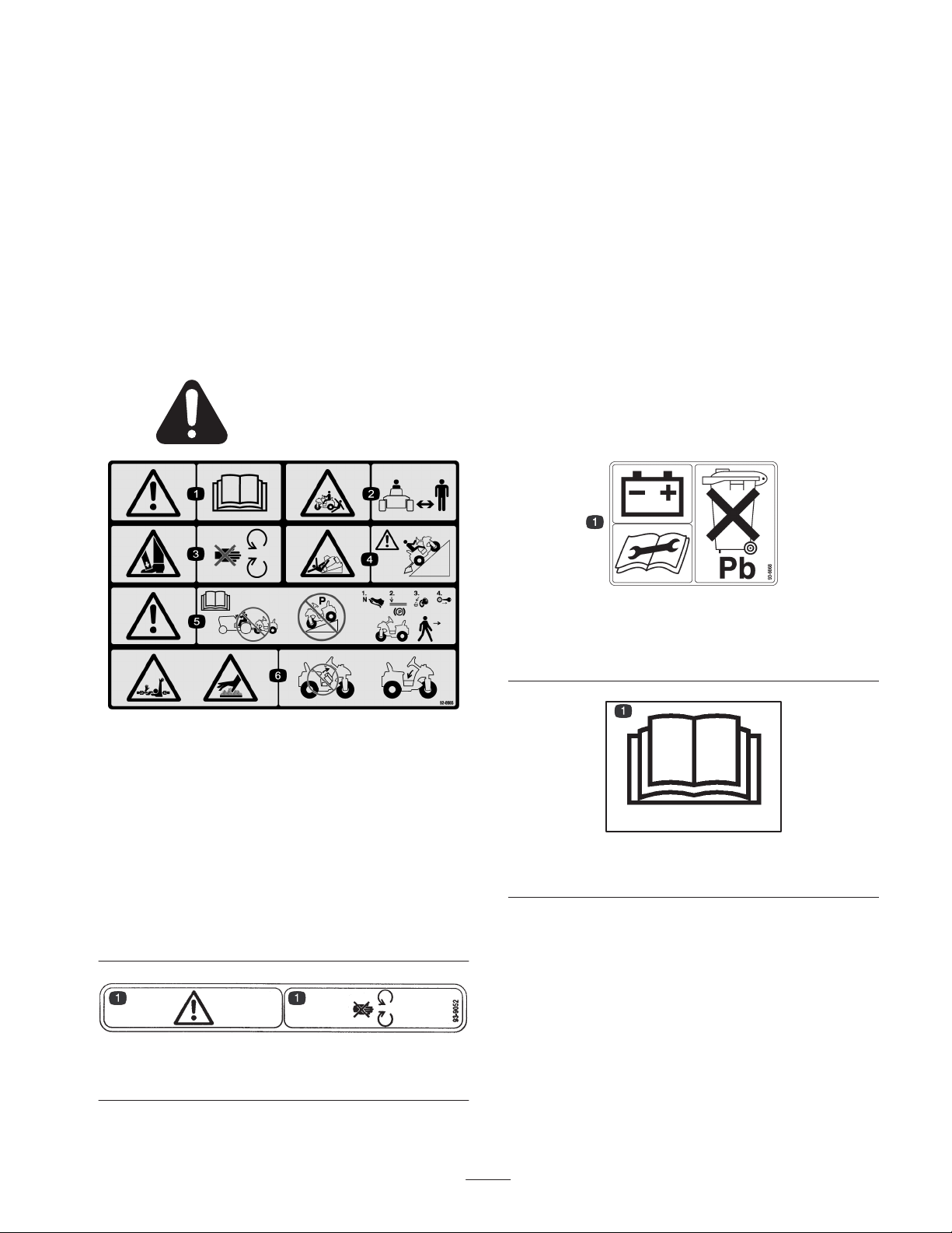
Safety and Instruction Decals
Safety decals and instructions are easily visible to the operator and are located near any area
of potential danger. Replace any decal that is damaged or lost.
Whole Body
This unit does not exceed a vibration level of 0.5 m/s@ at
the posterior based on measurements of identical machines
per EN 1032.
92-8985
1. Warning—read the Operator’s Manual.
2. Crushing/dismemberment hazard, bystanders—keep
bystanders a safe distance from the machine.
3. Crushing hazard of foot—keep guards in place, stay away from
moving parts.
4. Tipping hazards—Use caution when operating on slopes.
5. Warning—read the Operator’s Manual, do not tow the
machine; do not park the machine on a slope; before leaving
the machine, put the traction control pedal in neutral, lower the
implement, turn the engine off, and remove the ignition key.
6. Entanglement hazard, shaft; burn hazard—do not operate the
machine without the center shroud in place and the seat
latched.
93-9052
1. Warning—stay away from moving parts.
93-6668
1. The battery contains lead. Do not throw the battery in the
garbage. Read the operator’s manual before performing
maintenance.
93-9051
93-9051
1. Read the operator’s manual.
5
Page 6
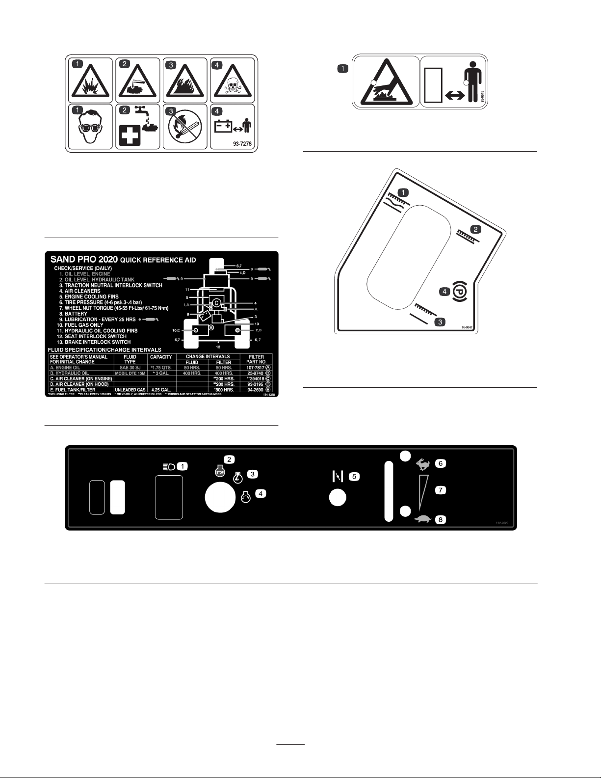
93-7276
1. Explosion hazard—wear eye protection.
2. Chemical burns to hands—flush with water and seek medical
attention.
3. Fire hazard—no sparks, flame, or smoking.
4. Poison—keep children away from the battery.
95-0645
1. Hot surface—keep bystanders away.
95-0647
1. Implement float position
2. Implement lower position
3. Implement raise position
4. Parking brake
1. Headlights
2. Engine—stop
114-4318
3. Engine—run
4. Engine—start
112-7629
5. Choke
6. Fast
7. Continuous variable setting
8. Slow
6
Page 7

Specifications
General Specifications
Configuration
Engine
Instrumentation Hour meter
Gas Tank 4-1/4 gallon (16.1 l) capacity
Battery 12 volt, lead acid, 32 amp. hour
Drive
Hydraulic Oil Filter 25 micron, spin-on type
Hydraulic Oil Reservoir 3 gallon (11.4 l) capacity
Valve Single section for raising and lowering of implement with float and holding checks.
Cylinder Double acting
Wheel Bearings Tapered roller bearing in each wheel motor. Roller bearings on front spindle.
Tires
Speeds (at 3200 RPM)
Seat Adjustment 4 inches (10.2 cm) fore and aft. Secondary position adds 2.5 inches (6.4 cm) fore.
Short wheel base tricycle vehicle with mid engine placement. Rear wheels
powered. Front wheel steering. Operator positioned centrally.
Briggs & Stratton, V-twin cylinder, 4 cycle, OHV, air cooled, gas engine with cast
iron sleeves. 16 hp @ 3600 RPM, 29.3 cu. in. (480 cc) displacement, 1-3/4 US qt.
(1.66 l) oil capacity. Electronic ignition. Full pressure lubrication, oil filter. Engine
and remote mounted air cleaners.
Hydraulic. Coupling driven variable displacement piston pump with integral auxiliary
charge pump to geroller motors which directly drive wheels.
22 x 11.00-8 two-ply pneumatic tubeless. De-mountable and interchangeable.
Recommended tire pressure is 4–6 psi (28–41 kPa).
Variable between 0 and 9 MPH (0 and 14 km/h) forward and 0 and 4 MPH (0 and
6 km/h) reverse.
Measurements
Width without implement 57-1/2 in. (146 cm)
Width with rake Model No.
08812
Height 45 in. (114 cm)
Length without rake 76 in. (193 cm)
Net weight (wet) 650 lb.( 295 kg)
75 in. (191 cm)
7
Page 8

Setup
Note: Determine the left and right sides of the machine from the normal operating position.
Loose Parts
Note: Use this chart as a checklist to ensure that all parts necessary for assembly have been shipped. If any of these parts are
missing, total setup cannot be completed.
Description
Steering wheel
Roll pin, 1/4 x 2 in.
Capscrew, 5/16 x 5/8 in.
Locknut, 5/16 in.
Capscrew, 1/2 x 1-1/4 in.
Washer, 1/2 in.
Cylinder pin
Cotter pin
Decal 2 Affix on machine, if desired.
Key
Parts catalog
Operator’s Manual
Engine Operator’s Manual
Operator Training Material
Registration card 1 Fill out and return to Toro.
Qty. Use
1
Mounting the steering wheel
1
2
Securing the battery cables to the battery
2
4
Attaching the implements to the frame
4
1
Attaching the cylinder to the implement
2
2
1
1
Read before operating the machine.
1
Note: Specifications and design subject to change without notice.
8
Page 9
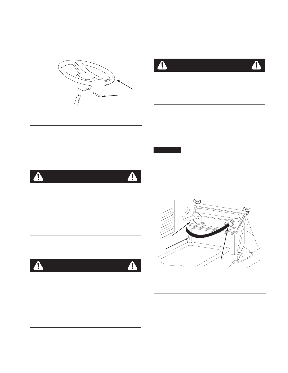
Installing the Steering Wheel
1. Move the front wheel so that it points straight ahead.
2. Slide the steering wheel onto the steering shaft, aligning
the mounting holes(Fig. 1).
1
2
1. Remove the filler caps from the battery and slowly fill
each cell until electrolyte is up to the fill line.
2. Replace the filler caps and connect a 3 to 4 amp. battery
charger to the battery posts. Charge the battery at a rate
of 3 to 4 amperes for 4 to 8 hours.
Warning
Charging the battery produces gasses that can
explode.
Never smoke near the battery and keep sparks and
flames away from battery.
Figure 1
1. Steering wheel 2. Roll pin
3. Secure the steering wheel in place with the roll pin
(Fig. 1).
Activating and Charging the
Battery
Warning
CALIFORNIA
Proposition 65 Warning
Battery posts, terminals, and related accessories
contain lead and lead compounds, chemicals
known to the State of California to cause cancer
and reproductive harm. Wash hands after
handling.
If the battery is not filled with electrolyte or activated, bulk
electrolyte with 1.260 specific gravity must be purchased
from a local battery supply outlet and added to the battery.
3. When the battery is charged, disconnect the charger
from the electrical outlet and battery posts. Allow the
battery to sit for 5–10 minutes.
4. Remove the filler caps. Slowly add electrolyte to each
cell until the level is up to the fill line. Install the filler
caps.
Important Do not overfill the battery. Electrolyte will
overflow onto other parts of the machine and severe
corrosion and deterioration will result.
Installing the Battery
1. Set the battery in place, with the negative (–) terminal
to the outside (Fig. 2).
2
1
Danger
Battery electrolyte contains sulfuric acid which is a
deadly poison and causes severe burns.
• Do not drink electrolyte and avoid contact with
skin, eyes or clothing. Wear safety glasses to
shield your eyes and rubber gloves to protect
your hands.
• Fill the battery where clean water is always
available for flushing the skin.
3
Figure 2
1. Battery
2. Positive (+) terminal
2. Secure the positive cable (red), which is the wire
attached to the solenoid under the front shroud, to the
positive (+) terminal with a capscrew and locknut.
9
3. Negative (–) terminal
Page 10
Warning
Incorrect battery cable routing could damage the
machine and cables causing sparks. Sparks can
cause the battery gasses to explode, resulting in
personal injury.
• Always disconnect the negative (black) battery
cable before disconnecting the positive (red)
cable.
• Always connect the positive (red) battery cable
before connecting the negative (black) cable.
Warning
Battery terminals or metal tools could short
against metal machine components causing sparks.
Sparks can cause the battery gasses to explode,
resulting in personal injury.
• When removing or installing the battery, do not
allow the battery terminals to touch any metal
parts of the machine.
• Do not allow metal tools to short between the
battery terminals and metal parts of the
machine.
3. Secure the negative cable (black) to the negative (–)
terminal of the battery with a capscrew and locknut
(Fig. 2).
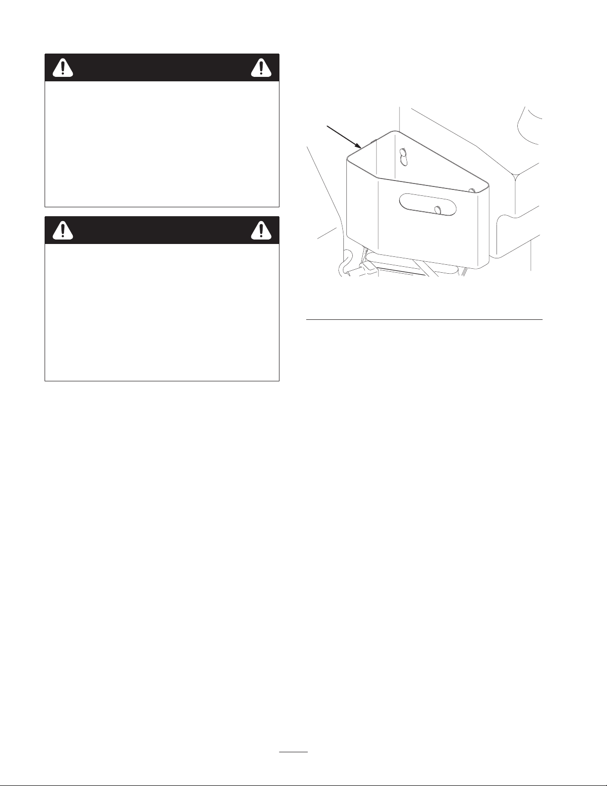
Installing the Refuse Container
Slide the refuse container onto the mounting studs on the
front of the fuel tank (Fig. 3).
1
Figure 3
1. Refuse container
Installing the Decals
Affix an Infield Pro® decal over each Sand Pro decal, if
desired.
4. Coat the terminals and mounting fasteners with
petroleum jelly to prevent corrosion. Slide the rubber
boot over the positive (+) terminal to prevent a possible
short from occurring.
5. Install the battery clamp and secure the battery with the
rods and wing nuts.
10
Page 11
Before Operating
Caution
If you leave the key in the ignition switch, someone
could accidently start the engine and seriously
injure you or other bystanders.
Remove the key from the ignition and disconnect
the wire from the spark plug before you do any
maintenance. Set the wire aside so that it does not
accidentally contact the spark plug.
Checking the Crankcase Oil
The engine is shipped with oil in the crankcase; however,
the oil level must be checked before and after the engine is
first started.
Crankcase capacity is approximately 1–3/4 US quarts
(1.66 l) with the filter.
Use high-quality engine oil that meets the following
specifications:
API Classification Level Required: SJ, SK, SL or
higher.
Preferred oil: SAE 30 (above 40 degrees F)
1. Position the machine on a level surface.
2. Pivot the seat rearward.
3. Pull out the dipstick (Fig. 4) and wipe it with a clean
rag. Insert the dipstick into the tube and make sure that
it is seated fully. Remove the dipstick from the tube and
check the oil level. If the oil level is low, remove the
filler cap from the valve cover and add enough oil to
raise the level to the FULL mark on the dipstick.
1
2
Figure 4
1. Dipstick 2. Filler cap
4. Install the dipstick firmly in place.
Important The dipstick must be fully seated in the tube
to provide proper sealing of the engine crankcase. Failure
to seal the crankcase may result in engine damage.
5. Install the engine cover.
Important Check the oil level every 8 operating hours
or daily. Initially, change the oil and filter after the first 8
hours of operation; thereafter, under normal conditions,
change the oil and filter every 50 hours. However, change
the oil more frequently when the engine is operated in
extremely dusty or dirty conditions.
Important Be sure to keep the engine oil level between
the upper and lower limits on the oil gauge. Engine failure
may occur as a result of over filling or under filling the
engine oil.
11
Page 12

Filling the Fuel Tank
Use UNLEADED Regular Gasoline suitable for automotive
use (87 pump octane minimum). Leaded regular gasoline
may be used if unleaded regular is not available.
Important Never use methanol, gasoline containing
methanol, or gasohol containing more than 10% ethanol
because the fuel system could be damaged. Do not mix oil
with gasoline.
Danger
In certain conditions, gasoline is extremely
flammable and highly explosive. A fire or
explosion from gasoline can burn you and others
and can damage property.
• Fill the fuel tank outdoors, in an open area,
when the engine is cold. Wipe up any gasoline
that spills.
• Do not fill the fuel tank completely full. Add
gasoline to the fuel tank until the level is 1 in.
(25 mm) below the bottom of the filler neck.
This empty space in the tank allows gasoline to
expand.
• Never smoke when handling gasoline, and stay
away from an open flame or where gasoline
fumes may be ignited by a spark.
• Store gasoline in an approved container and
keep it out of the reach of children. Never buy
more than a 30-day supply of gasoline.
• Always place gasoline containers on the ground
away from your vehicle before filling.
• Do not fill gasoline containers inside a vehicle or
on a truck or trailer bed because interior
carpets or plastic truck bed liners may insulate
the container and slow the loss of any static
charge.
• When practical, remove gas-powered equipment
from the truck or trailer and refuel the
equipment with its wheels on the ground.
• If this is not possible, then refuel such
equipment on a truck or trailer from a portable
container, rather than from a gasoline dispenser
nozzle.
• If a gasoline dispenser nozzle must be used, keep
the nozzle in contact with the rim of the fuel
tank or container opening at all times until
fueling is complete.
Warning
Gasoline is harmful or fatal if swallowed.
Long-term exposure to vapors can cause serious
injury and illness.
• Avoid prolonged breathing of vapors.
• Keep face away from nozzle and gas tank or
conditioner opening.
• Keep gas away from eyes and skin.
Fuel tank capacity is approximately 4-1/4 gallons (16.1 l).
1. Clean the area around the fuel tank cap (Fig. 5).
2. Remove the fuel tank cap.
3. Fill the tank to about 1 in. (25 mm) below the top of the
tank (bottom of the filler neck). Do not overfill. Install
the cap.
4. Wipe up any fuel that may have spilled to prevent a fire
hazard.
1
Figure 5
1. Fuel tank cap
12
Page 13

Checking the Hydraulic System
The machines reservoir is filled at the factory with
approximately 3 U.S. gallons (11.4 l) of high quality
hydraulic fluid. Check the level of the hydraulic fluid
before the engine is first started and daily thereafter.
The recommended replacement fluid is:
Toro Premium All Season Hydraulic Fluid
(Available in 5 gallon pails or 55 gallon drums. See
parts catalog or Toro distributor for part numbers.)
Alternate fluids: If the Toro fluid is not available, other
fluids may be used provided they meet all the following
material properties and industry specifications. We do not
recommend the use of synthetic fluid. Consult with your
lubricant distributor to identify a satisfactory product
Note: Toro will not assume responsibility for damage
caused by improper substitutions, so use only products
from reputable manufacturers who will stand behind their
recommendation.
High Viscosity Index/Low Pour Point Antiwear
Hydraulic Fluid, ISO VG 46
Material Properties:
Viscosity, ASTM D445 cSt @ 40_C 44 to 48
cSt @ 100_C 9.1 to 9.8
Viscosity Index ASTM D2270 140 to 160
Pour Point, ASTM D97 –34_F to –49_F
2. Remove the cap from the hydraulic oil reservoir
(Fig. 6).
1
Figure 6
1. Oil reservoir cap
3. Check the oil level in the reservoir. The oil level should
be up to the top of the cone point on the tank screen.
4. If the fluid level is low, slowly fill the reservoir with the
appropriate hydraulic fluid until the level reaches the
bottom of the screen. Do not overfill.
5. Install the reservoir cap.
Important To prevent system contamination, clean the
top of the hydraulic oil containers before puncturing.
Ensure that the pour spout and funnel are clean.
Industry Specifications:
Vickers I–286–S (Quality Level), Vickers M–2950–S
(Quality Level), Denison HF–0
Note: Many hydraulic fluids are almost colorless, making it
difficult to spot leaks. A red dye additive for the hydraulic
system oil is available in 2/3 oz. (20 ml) bottles. One bottle
is sufficient for 4–6 gal (15–22 1) of hydraulic oil. Order
part no. 44–2500 from your authorized Toro distributor.
Biodegradable Hydraulic Fluid – Mobil 224H
Toro Biodegradable Hydraulic Fluid
(Available in 5 gallon pails or 55 gallon drums. See
parts catalog or Toro distributor for part numbers.)
Alternate fluid: Mobil EAL 224H
This is vegetable–oil based biodegradable oil tested and
approved by Toro for this model. This fluid is not as
resistant to high temperatures as standard fluid, so install an
oil cooler if required by the operator manual and follow
recommended fluid change intervals with this fluid.
Contamination by mineral–based hydraulic fluids will
change the biodegradability and toxicity of this oil. When
changing from standard fluid to the biodegradable type, be
certain to follow the approved flushing procedure. Contact
your local Toro Distributor for details.
Checking the Tire Pressure
Check the tire pressure before operating the machine. The
correct air pressure in the front and rear tires is 4–6 psi
(28–41 kPa).
1. Clean the area around the hydraulic oil reservoir cap to
prevent debris from entering the tank (Fig. 6).
13
Page 14

Operation
Note: Determine the left and right sides of the machine
from the normal operating position.
Important For maximum pulling power, the throttle
should be in the Fast position and the traction pedal just
barely depressed.
Caution
Using the Controls
Traction and Stopping Pedal
The traction pedal (Fig. 7) has 3 functions: to make the
machine move forward, to move it backward, and to stop
the machine. Using the heel and toe of the right foot,
depress the top of the pedal to move forward and the
bottom of pedal to move backward or to assist in stopping
when moving forward (Fig. 8). Also, allow the pedal to
move or move it to the neutral position to stop the machine.
For operator comfort, do not the rest heel of the foot on
reverse when operating forward (Fig. 10).
1
Figure 7
1. Traction and stopping pedal
Use the maximum ground speed only when driving
from one area to another.
Maximum speed is not recommended when using
an attached or towed implement.
Important Do not operate in reverse with the
implement in the down (operating) position, or the
implement could be severely damaged.
Ignition Switch
The ignition switch (Fig. 9), used to start and stop the
engine, has three positions: Off, Run, and Start. Rotate the
key clockwise to the Start position to engage the starter
motor. Release the key when the engine starts. The key will
move automatically to the On position. To shut the engine
off, rotate the key counterclockwise to the Off position.
Choke Control
To start a cold engine, close the carburetor choke by pulling
the choke control (Fig. 9) out to the On position. After the
engine starts, regulate the choke to keep the engine running
smoothly. As soon as possible, open the choke by pushing
it downward to the Off position. A warm engine requires
little or no choking.
4
Figure 8
Ground speed is proportionate to how far the traction pedal
is depressed. For maximum ground speed, the pedal must
be fully depressed while the throttle is in the Fast position.
To get maximum power or when ascending a hill, have the
throttle in the Fast position while depressing the pedal
slightly to keep the engine RPM high. When the engine
RPM begins to decrease, release the pedal slightly to allow
the RPM to increase.
5
7
1. Ignition switch
2. Choke control
3. Throttle control
4. Hour meter
14
6
1
2
3
Figure 9
5. Fuse (option lights)
6. Lights (optional)
7. Fuse (main)
Page 15

Throttle Control
Fuel Shutoff Valve
The throttle control lever (Fig. 9) connects to and operates
the throttle linkage to the carburetor. The control has 2
positions: Slow and Fast. The engine speed can be varied
between the 2 settings.
Note: The engine cannot be stopped by the throttle control.
Hour Meter
The hour meter (Fig. 9) indicates the total hours of machine
operation. The hour meter starts to function whenever the
key switch is rotated to the On position.
Lift Lever
To raise the implement, pull the lift lever (Fig. 10) back; to
lower the implement, push the lever forward. For the float
position, move the lever into the detent position. When the
desired position is attained, release the lever and it will
return to neutral.
Note: The machine has a double-acting lift cylinder. Down
pressure can be applied to the implement for certain
operating conditions.
Parking Brake
To engage the parking brake (Fig. 10), pull back on the
lever. To disengage it, push the lever forward.
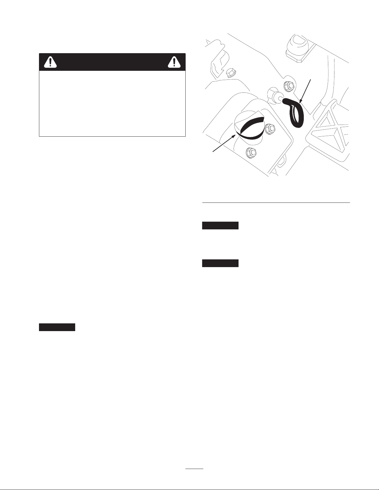
Close the fuel shutoff valve (Fig. 11) when storing the
machine.
1
Figure 11
1. Fuel shutoff valve
Seat Adjustment
Move the lever on the side of the seat outward, slide the
seat to the desired position, and release the lever to lock the
seat into position.
An additional 2–1/2 inches of forward adjustment may be
attained by , proceed as follows:
2
Figure 10
1. Lift lever 2. Parking brake
1. Remove the (4) locknuts securing the seat slides to the
1
seat plate.
2. Move the seat/slides to the forward set of mounting
holes in the seat plate.
3. Secure the seat slides to the seat plate with the locknuts
previously removed.
15
Page 16

Operation
Note: Determine the left and right sides of the machine
from the normal operating position.
Checking the Interlock System
Operation
Caution
Starting and Stopping the
Engine
1. Remove your foot from the traction pedal, make sure
that the pedal is in the neutral position, and engage the
parking brake.
2. Pull the choke lever out to the On position (when
starting a cold engine) and the throttle lever to the Slow
position.
3. Insert the key into the ignition switch and rotate it
clockwise to start the engine. Release the key when the
engine starts. Regulate the choke to keep the engine
running smoothly.
Important To prevent overheating of the starter motor,
do not engage the starter longer than 10 seconds. After 10
seconds of continuous cranking, wait 60 seconds before
engaging the starter motor again.
4. When the engine is started for the first time, or after an
overhaul of the engine, operate the machine in forward
and reverse for 1 to 2 minutes. Also operate the lift
lever to be sure of proper operation of all parts.
5. To stop the engine, move the throttle control to the Slow
position and rotate the ignition key to Off. Remove the
key from the switch to prevent accidental starting.
6. Close the fuel shutoff valve before storing the machine.
Caution
Shut the engine off and wait for all moving parts to
stop before checking for oil leaks, loose parts, and
other malfunctions.
If safety interlock switches are disconnected or
damaged the machine could operate unexpectedly
causing personal injury.
• Do not tamper with the interlock switches.
• Check the operation of the interlock switches
daily and replace any damaged switches before
operating the machine.
The purpose of the interlock system is to prevent the engine
from cranking or starting unless the traction pedal is in the
neutral position.
1. Check the interlock operation in a wide open area free
of debris and bystanders. Stop the engine.
2. Sit on the seat. Depress the traction pedal in forward
and reverse while trying to start the engine. If the
engine cranks, there may be a malfunction in the
interlock system. Repair it immediately. If the engine
does not crank, the system is operating correctly.
3. With the operator on the seat and the engine running,
raise off the seat while depressing the traction pedal.
The engine should stop within 2 seconds. If the engine
does not stop, there may be a malfunction in the
interlock system. Repair it immediately. If the engine
does stop, the system is operating correctly.
4. With the operator on the seat, the parking brake
engaged and the engine running, Depress the traction
pedal in forward and reverse. The engine should stop
within 2 seconds. If the engine does not stop, there may
be a malfunction in the interlock system. Repair it
immediately. If the engine does stop, the system is
operating correctly.
Towing the Machine
In case of emergency, the machine can be towed for a short
distance. However, we do not recommend this as a standard
procedure.
Important Do not tow the machine faster than
2–3 MPH (3–5 km/h) because the drive system may be
damaged. If the machine must be moved a considerable
distance, transport it on a truck or trailer. The tires may
lock up if the machine is towed too fast. If this occurs, stop
towing the machine and wait for the traction circuit
pressure to stabilize before resuming towing at a slower
speed.
16
Page 17

Break-In Period
Inspecting and Cleaning the
Only 8 hours of operating time is required for the break-in
period.
Since the first hours of operation are critical to future
dependability of the machine, monitor its functions and
performance closely so that minor difficulties, which could
lead to major problems, are noted and can be corrected.
Inspect the machine frequently during break-in for signs of
oil leakage, loose fasteners, or any other malfunction.
Operating Characteristics
Practice driving the machine because its operating
characteristics are different than some utility vehicles. Two
points to consider when operating the vehicle are
transmission and engine speed.
To maintain somewhat constant engine RPM, depress the
traction pedal slowly. This allows the engine to keep up
with the ground speed of the vehicle. By contrast, pushing
down quickly on the traction pedal will reduce engine RPM
and, as a result, there will not be enough torque-power to
move the vehicle. Therefore, to transfer maximum power to
the rear wheels, move the throttle to Fast and slightly
depress the traction pedal. By comparison, maximum
ground speed with no load results when the throttle is in the
Fast position and the traction pedal is slowly but fully
depressed. In summary, always keep the engine RPM high
enough to deliver maximum torque-power to the rear
wheels.
Machine
At the completion of operation, thoroughly wash the
machine with a garden hose—without a nozzle—so that
excessive water pressure will not cause contamination and
damage to the seals and bearings.
Make sure that the cooling fins and area around the engine
cooling air intake are kept free of debris. After cleaning,
inspect the machine for possible hydraulic fluid leaks,
damage, or wear to hydraulic and mechanical components.
Caution
Operating the machine demands attention to
prevent tipping or loss of control.
• Use care when entering and leaving sand traps.
• Use extreme caution around ditches, creeks, or
other hazards.
• Use caution when operating the machine on a
steep slope.
• Reduce your speed when making sharp turns or
when turning on hillsides.
• Avoid sudden stops and starts.
• Do not go from reverse to full forward without
first coming to a complete stop.
17
Page 18

Maintenance
Note: Determine the left and right sides of the machine from the normal operating position.
Recommended Maintenance Schedule
Maintenance Service
Interval
After first 8 hours
Before each use or
daily
Every 25 hours
Every 50 hours • Change the engine oil and filter.
Every 100 hours
Maintenance Procedure
• Change the engine oil and filter.
• Torque the wheel lug nuts.
• Change the hydraulic oil filter.
• Check the operation of the interlock switches.
• Check the engine oil level.
• Check the hydraulic fluid level.
• Check the tire pressure.
• Check the condition of the hydraulic .
• Inspect and clean the machine.
• Check the battery fluid level.
• Check the battery cable connections.
• Lubricate the front wheel bearing.
• Lubricate the traction control linkage.
• Inspect the remote air filter element.
• Inspect the engine air filter element.
• Lubricate the steering shaft grease fitting.
• Check the steering chain adjustment.
• Torque the wheel lug nuts.
Every 200 hours
Every 400 hours or
annually, whichever
occurs first
Every 800 hours
Every 1500 hours or 2
years, whichever occurs
first
Important Refer to your engine operator’s manual for additional maintenance procedures.
• Replace the remote air filter element.
• Replace the engine air filter element.
• Change the hydraulic oil.
• Replace the hydraulic oil filter.
• Replace the spark plugs.
• Replace the fuel filter.
• Decarbon the combustion chamber.
• Adjust the valves and torque head.
• Check the engine RPM (at idle and full throttle).
• Drain and clean the fuel tank.
• Replace moving hoses.
18
Page 19

Daily Maintenance Checklist
Duplicate this page for routine use.
For the week of:
Maintenance Check Item
Check safety interlock operation.
Check steering operation.
Check the engine oil level.
Check the air filter/pre-cleaner condition.
Clean the engine cooling fins.
Check unusual engine noises.
Check unusual operating noises.
Check the hydraulic system oil level.
Check the hydraulic hoses for damage.
Check for fluid leaks.
Check the fuel level.
Check the tire pressure.
Check instrument operation.
Touch up damaged paint.
Notation for Areas of Concern
Inspection performed by:
Mon. Tues. Wed. Thurs. Fri. Sat. Sun.
Item Date Information
1
2
3
4
5
6
7
8
9
10
11
12
13
14
15
16
19
Page 20

Caution
If you leave the key in the ignition switch, someone could accidently start the engine and
seriously injure you or other bystanders.
Remove the key from the ignition and disconnect the wire from the spark plug before you do any
maintenance. Set the wire aside so that it does not accidentally contact the spark plug.
Lubricating the Machine
The machine has 3 grease fittings that must be lubricated
regularly with No. 2 General Purpose Lithium Base Grease.
Lubricate the front wheel bearings after every 25 hours of
operation. Lubricate the steering shaft every 100 hours.
Lubricate the following bearings and bushings:
• Front wheel bearings (Qty. 2) (Fig. 12)
• Steering shaft and sprocket (Fig. 13)
1. Wipe the grease fitting clean so that foreign matter
cannot be forced into the bearing or bushing.
2. Pump grease into the bearing or bushing.
3. Wipe up excess grease.
Figure 13
Figure 12
Note: Do not lubricate the steering chain unless it becomes
stiff because of rust. If the chain rusts, it may be lubricated
lightly with a dry-type lubricant.
20
Page 21

Changing the Engine Oil and
Filter
4. Remove the filter and cover plate. Inspect the filter for
cleanliness, ruptures, holes, and tears. Replace a
damaged filter element.
Change the oil and filter initially after the first 8 hours of
operation; thereafter change the oil and the filter every 50
hours.
1. Park the machine on a level surface and turn the engine
off.
2. Remove the drain plug (Fig. 14) and let oil flow into a
drain pan. When the oil stops, install the drain plug.
3. Remove the oil filter (Fig. 14). Apply a light coat of
clean oil to the new filter gasket.
1
2
Figure 14
1. Drain plug 2. Oil filter
Important With the air cleaner disassembled, check the
air cleaner components for damage. Replace them if
necessary. Make sure that the rubber breather tube in the
base plate is securely in place or severe engine damage may
occur.
1
2
Figure 15
1. Air cleaner cover 2. Paper element
5. Install the air cleaner element and cover plate.
4. Screw the filter on by hand until the gasket contacts the
filter adapter; then tighten 1/2 to 3/4 turn further. Do
not overtighten.
5. Add oil to the crankcase; refer to Checking the
Crankcase Oil.
6. Dispose of used oil properly.
Servicing the Engine Air
Cleaner
Inspect the paper element every 100 hours of operation and
replace it every 200 hours or when it becomes dirty or
damaged. Do not wash the paper element or do not clean it
with compressed air as damage will occur.
1. Park the machine on a level surface and turn the engine
off.
2. Pivot the seat upward.
3. Remove the knobs and air cleaner cover (Fig. 15).
6. Install the air cleaner cover and secure it with the knobs.
General Air Cleaner
Maintenance
Check the air cleaner body for damage which could
possibly cause an air leak. Replace a damaged air cleaner
body.
Replace the air cleaner filter every 200 hours (more
frequently in extremely dusty or dirty conditions). Do not
over-service the air filter.
Be sure that the cover is sealing around the air cleaner
body.
Servicing the Remote Air
Cleaner
1. Release the latches securing the air cleaner cover to the
air cleaner body (Fig. 16). Separate the cover from the
body. Clean the inside of the air cleaner cover.
21
Page 22

Adjusting the Throttle Control
1
3
Figure 16
1. Air cleaner latches
2. Dust cap
3. Filter
2. Washing Method
A. Prepare a solution of filter cleaner and water and
soak the filter element about 15 minutes. Refer to
the directions on the filter cleaner carton for
complete information.
B. After soaking the filter for 15 minutes, rinse it with
clear water. Maximum water pressure must not
exceed 40 psi (276 kPa) to prevent damage to the
filter element. Rinse the filter from the clean side to
the dirty side.
C. Dry the filter element using warm, flowing air
(160°F [71°C] max), or allow the element to air-dry.
Do not use a light bulb to dry the filter element
because damage could result.
3. Compressed Air Method
A. Blow compressed air from the inside to the outside
of a dry filter element. Do not exceed 100 psi
(689 kPa) to prevent damage to the element.
B. Keep the air hose nozzle at least 2 in. (5 cm) from
the filter and move the nozzle up and down while
rotating the filter element. Inspect the filter for holes
and tears by looking through the filter toward a
bright light.
4. Inspect the new filter for shipping damage. Check the
sealing end of the filter. Do not install a damaged filter.
5. Insert the new filter properly into the air cleaner body.
Make sure that the filter is sealed properly by applying
pressure to the outer rim of the filter when installing it.
Do not press on the flexible center of the filter.
Proper throttle operation is dependent upon proper
2
adjustment of the throttle control. Before adjusting the
carburetor, ensure that the throttle control is operating
properly.
1. Pivot the seat upward and remove the engine shield.
2. Loosen the cable clamp screw securing the cable to the
engine (Fig. 17).
3. Move the remote throttle control lever forward to the
Fast position.
5
6
4
3
1
2
Figure 17
1. Throttle casing clamp
screw
2. Throttle cable
3. Swivel
4. Stop
5. Choke casing clamp
screw
6. Choke cable
4. Pull firmly on the throttle cable until the back of the
swivel contacts the stop (Fig. 17).
5. Tighten the cable clamp screw and check the engine
RPM setting:
High Idle: 3150±50
Low Idle: 1750±50
Adjusting the Choke Control
1. Pivot the seat upward and remove the engine shield.
2. Loosen the cable clamp screw securing the cable to the
engine (Fig. 17).
3. Move the remote choke control lever forward to the
Closed position.
6. Install the cover and secure the latches. Make sure that
the cover is positioned with the TOP side up.
4. Pull firmly on the choke cable (Fig. 17) until the choke
butterfly is completely closed; then tighten the cable
clamp screw.
22
Page 23

Adjust the Engine Governor
Speed Control
4. Adjust the idle stop screw until the idle speed is
increased 25 to 50 RPM over the idle speed set in step
3. Final idle speed must be 1750$100 RPM.
Important Before the engine governor speed control is
adjusted, the throttle and choke controls must be adjusted
properly.
Warning
The engine must be running during the adjustment
of the engine governor speed control. Contact with
moving parts or hot surfaces may cause personal
injury.
• Ensure traction pedal is in neutral and engage
the parking brake before performing
this procedure.
• Keep hands, feet, face, and other body parts
away from rotating parts, the muffler, and other
hot surfaces.
Note: To adjust the low idle, use all the following steps. If
only the high idle is to be adjusted, proceed directly to
step 5.
1. Start the engine and let it run at half throttle for
approximately five minutes to warm up.
2. Move the throttle control to the Slow setting. Adjust the
idle stop screw counterclockwise until it no longer
contacts the throttle lever.
3. Bend the governed idle spring anchor tang (Fig. 18) to
attain an idle speed of 1750$50 RPM. Check the speed
with a tachometer.
5. Move the throttle control to the Fast position. Bend the
high speed spring anchor tang (Fig. 18) to attain a high
speed of 3150$50 RPM.
Replacing the Spark Plugs
Replace the spark plugs after every 800 operating hours or
yearly, whichever occurs first.
Type: Champion RC12YC (or equivalent)
Air Gap: 0.030 in. (0.76 mm)
Note: The spark plug usually lasts a long time; however,
the plug should be removed and checked whenever the
engine malfunctions.
1. Clean the area around the spark plugs so that foreign
matter cannot fall into the cylinder when the spark plug
is removed.
2. Pull the spark plug wires off of the spark plugs and
remove the plugs from the cylinder head.
3. Check the condition of the side electrode, center
electrode, and center electrode insulator to ensure that
there is no damage.
Important A cracked, fouled, dirty, or otherwise
malfunctioning spark plug must be replaced. Do not
sand-blast, scrape, or clean the electrodes by using a wire
brush because grit may eventually release from the plug
and fall into the cylinder. The result is usually a damaged
engine.
1
Shown with Carb Adapter Removed
1. Governed idle spring
anchor tag
4. Set the air gap between the center and side of the
electrodes at 0.030 in. (0.76 mm) (Fig. 19). Install the
correctly gapped spark plug with gasket seal, and
tighten the plug to 200 in.-lb. (23 N⋅m). If a torque
wrench is not used, tighten the plug firmly.
2
0.030 in.
(0.76 mm)
Figure 19
Figure 18
2. High speed spring anchor
tag
23
Page 24

Cleaning the Cylinder Head
Fins
8. Run the engine until the lift cylinder extends and
retracts and forward and reverse wheel motion is
achieved.
To avoid overheating and possible engine damage, the
cooling fins on the cylinder head must be kept clean.
Changing the Hydraulic
System Oil and Filter
The hydraulic system filter must be changed initially, after
the first 8 hours of operation, and thereafter every 400
hours of operation or yearly, whichever occurs first. Use a
genuine Toro oil filter for replacement. The hydraulic oil
must be changed every 400 hours of operation or yearly,
whichever occurs first.
1. Park the machine on a level surface and turn the engine
off.
2. Pivot the seat upward.
3. Disconnect the tube from the bottom fitting of the
reservoir and let the oil flow into a drain pan. Install and
tighten the tube when the oil stops draining.
4. Clean the area around the hydraulic oil filter (Fig. 20).
Remove the filter from the bottom of the filter housing
and allow the oil to flow into a drain pan. Use a
bottom-type filter wrench. Dispose of the oil filter
properly.
9. Stop the engine and check the oil level in the reservoir.
Add oil if necessary.
10. Check all connections for leaks.
11. Lower the seat.
12. Dispose of used oil properly.
Checking the Hydraulic Lines
and Hoses
Check the hydraulic lines and hoses daily for leaks, kinked
lines, loose mounting supports, wear, loose fittings, weather
deterioration, and chemical deterioration. Make all
necessary repairs before operating.
Warning
Hydraulic fluid escaping under pressure can
penetrate skin and cause injury.
• Make sure all hydraulic fluid hoses and lines are
in good condition and all hydraulic connections
and fittings are tight before applying pressure to
the hydraulic system.
• Keep your body and hands away from pin hole
leaks or nozzles that eject high pressure
hydraulic fluid.
• Use cardboard or paper to find hydraulic leaks.
• Safely relieve all pressure in the hydraulic
system before performing any work on the
hydraulic system.
• Seek immediate medical attention if fluid is
injected into skin.
1
Figure 20
1. Hydraulic filter
5. Apply a film of oil on the filter gasket. Install the filter
by hand until the gasket contacts the mounting head;
then tighten the filter an additional 3/4 turn.
6. Fill the reservoir to the proper level; refer to Checking
the Hydraulic System.
7. Place all of the controls in the neutral or disengaged
position and start the engine. Run the engine at the
lowest possible RPM to purge the system of air.
Charging the Hydraulic System
Whenever a hydraulic component is repaired or replaced,
the hydraulic oil filter should be changed and the hydraulic
system charged.
Important Make sure that the hydraulic reservoir and
filter are filled with oil at all times when charging the
hydraulic system.
1. Park the machine on a level surface and turn the engine
off.
2. Pivot the seat upward and remove the engine shield.
3. Loosen the locknut on the spring adjusting pin until the
bearing moves freely from the cam on the lever
(Fig. 21), allowing the pump shaft freedom to rotate
during start-up.
24
Page 25

3
2
pump and reverse the locations. If the wheel rotates in
the proper direction, stop the engine and adjust the
spring adjusting pin locknut. Adjust the traction neutral
position; refer to Adjusting the Traction Drive for
Neutral.
8. Check the adjustment of the traction interlock switch;
refer to Adjusting the Traction Interlock Switch.
9. Install the engine shield and lower the seat.
Adjusting the Steering Chain
Since the chain and sprocket are subjected to sand thrown
up by the front tire, inspect them frequently for wear. If
either the chain or sprocket is worn beyond acceptable
limits, both should be replaced.
1
Figure 21
1. Spring adjusting pin
2. Bearing
4. Raise one rear wheel off of the floor and place support
blocks under the frame.
5. Start the engine and set the throttle to allow the engine
to run at approximately 1800 RPM.
6. Actuate the lift valve lever until the lift cylinder rod
moves in and out several times. If the cylinder rod does
not move after 10–15 seconds or the pump emits
abnormal sounds, shut the engine off immediately and
determine the cause or problem. Inspect for the
following:
• Loose filter or suction lines
• Loose or faulty coupler on the pump
• Blocked suction line
• Faulty charge relief valve
• Faulty charge pump
3. Cam
1. Place the front wheel in the straight ahead position.
2. Adjust the locknuts until the chain is snug on both sides
of the sprocket (Fig. 22).
3. Turn the steering wheel full left and full right to be sure
that the chain does not bind or hang up in either
direction. Adjust as required.
1
Figure 22
1. Adjusting nuts
If the cylinder moves in 10–15 seconds, proceed to
step 7.
Note: A hydrostatic transmission service manual (Bulletin
No. 9646) and a repair manual (Bulletin No. 9659) can be
obtained from:
Sundstrand Corporation
2800 East 13th Street
Ames, Iowa 50010
7. Operate the traction pedal in forward and reverse. The
wheel that is off of the floor should rotate in the proper
direction. If the wheel rotates in the wrong direction,
stop the engine, remove the lines from the rear of the
Replacing the Fuel Filter
An inline filter is incorporated into the fuel line. Change
the filter every 800 hours. Use the following procedures
when replacement becomes necessary:
1. Close the fuel shutoff valve.
2. Clamp both fuel lines that connect to the fuel filter
(Fig. 23) so that gasoline cannot drain when the lines
are removed.
3. Loosen the hose clamps at both ends of the filter and
pull the fuel lines off of the filter.
25
Page 26

2
1
Figure 23
1. Fuel filter 2. Hose clamps
4. Slide the hose clamps onto the ends of the fuel lines.
Push the fuel lines onto the fuel filter and secure them
with the hose clamps. Be sure that the arrow on the side
of the filter points toward the carburetor.
Adjusting the Traction Drive for
Neutral
If the machine moves when the traction pedal is in the
neutral position, the traction cam must be adjusted.
1. Park the machine on a level surface and turn the engine
off.
Warning
The engine must be running so that the final
adjustment of the traction adjustment cam can be
performed. Contact with moving parts or hot
surfaces may cause personal injury.
Keep hands, feet, face, and other body parts away
from rotating parts, the muffler, and other hot
surfaces.
5. Start the engine and rotate the cam hex (Fig. 24) in both
directions to determine the mid position of the neutral
span.
6. Tighten the locknut securing the adjustment.
7. Stop the engine.
8. Install the engine shield and lower the seat.
9. Remove the jack stands and lower the machine to the
shop floor. Test drive the machine to make sure that it
does not move when the traction pedal is in neutral.
Adjusting the Traction Interlock
Switch
2. Pivot the seat upward and remove the engine shield.
3. Raise one rear wheel off of the floor and place support
blocks under the frame.
4. Loosen the locknut on the traction adjustment cam
(Fig. 24).
1
2
3
4
Figure 24
1. Traction adjustment cam
2. Locknut
3. Screw
4. Gap
1. Adjust the transmission for neutral; refer to Adjusting
the Traction Drive for Neutral.
2. Activate the pump lever to ensure that all parts are
operating freely and seated properly.
3. Adjust the screw until the air gap is .060 inches $ .030
(Fig. 24).
4. Check for proper operation.
Adjusting the Pedal for
Forward
The pedal must be adjusted for forward if the jam nuts on
the control rod are loosened or if the pedal is removed.
1. Park the machine on a level surface, turn the engine off,
and engage the parking brake.
2. Make sure that the pump is in neutral.
3. Loosen the jam nuts on the control rod (Fig. 25).
4. Press down on the rear of the pedal until the pedal
contacts the footrest.
5. Adjust the jam nuts to allow full stroke of the pump,
slightly deflecting the control rod when the pedal is at
full stroke.
26
Page 27

1. Pedal
2. Jam nuts
1
Figure 25
3. Control rod
3
2
1
2
Figure 27
1. Brake switch mounting
nut
2. Parking brake lift lever
link
Adjusting the Brake Interlock
Switch
1. Park the machine on a level surface and turn the engine
off.
2. Disengage the parking brake.
3. Remove the knob from the lift lever (Fig. 26).
1
2
2
7. Engage and disengage the parking brake to make sure it
does not interfere with the switch.
8. Test for proper operation.
9. Install the valve shroud.
10. Adjust the lift lever guide. Refer to Adjusting the Lift
Lever, Page 27.
Adjusting the Brake Linkage
The brakes have been set at the factory for optimum
performance, but after use and wear an adjustment may be
required.
1. Park the machine on a level surface, turn the engine off,
and block the wheels.
2. Loosen the jam nut on the actuator rod (Fig. 28).
Remove the cotter pin retaining the actuator rod.
Increase or decrease the actuator rod length by rotating
the rod. Install the actuator rod using a new cotter pin
and secure the jam nut.
13 4
Figure 26
1. Lift lever knob 2. Valve shroud mounting
screws
4. Remove the (3) mounting screws and remove the valve
shroud (Fig. 26).
5. Loosen the (2) nuts securing brake interlock switch to
brake sensor bracket (Fig. 27).
6. Adjust the brake switch until the air gap between the
switch and the parking brake lever link is .060 inches $
.030. (Fig. 27). Tighten the switch mounting nuts.
1. Actuator rod
2. Adjustment rod (2)
27
4
2
3
Figure 28
3. Jam nut (3)
4. Cotter pin (3)
Page 28

3. If modifying the actuator rod length does not improve
brake performance, adjust both the left and right
adjustment rods equally using the same procedure
described in step 2.
Adjusting the Lift Lever
If the implement fails to float when the lift lever is in the
detent position, an adjustment to the lever guide is required.
Caring for the Battery
The battery electrolyte level must be properly maintained
and the top of the battery kept clean. lf the machine is
stored in a location where temperatures are extremely high,
the battery will run down more rapidly than if the machine
is stored in a location where temperatures are cool.
Danger
1. Park the machine on a level surface, turn the engine off,
and engage the parking brake.
2. Disconnect the implement from the lift cylinder and
extend the cylinder part way.
3. Loosen the capscrews and locknuts securing the lever
guide (Fig. 29) to the valve shroud.
4. Move the lever guide until the cylinder moves freely
when the lift lever is in the detent position.
5. Tighten the capscrews and locknuts locking the
adjustment.
1
2
Battery electrolyte contains sulfuric acid which is a
deadly poison and causes severe burns.
• Do not drink electrolyte and avoid contact with
skin, eyes or clothing. Wear safety glasses to
shield your eyes and rubber gloves to protect
your hands.
• Fill the battery where clean water is always
available for flushing the skin.
Keep the top of the battery clean by washing it periodically
with a brush dipped in ammonia or bicarbonate of soda
solution. Flush the top surface with water after cleaning.
Do not remove the fill cap while cleaning.
The battery cables must be tight on the terminals to provide
good electrical contact.
Warning
Incorrect battery cable routing could damage the
machine and cables causing sparks. Sparks can
cause the battery gasses to explode, resulting in
personal injury.
Figure 29
1. Lift lever 2. Lever guide
Storing the Battery
If the machine will be stored for more than 30 days, remove
the battery and charge it fully. Either store it on the shelf or
on the machine. Leave the cables disconnected if it is stored
on the machine. Store the battery in a cool atmosphere to
avoid quick deterioration of the charge in the battery. To
prevent the battery from freezing, make sure that it is fully
charged. The specific gravity of a fully charged battery is
1.250.
• Always disconnect the negative (black) battery
cable before disconnecting the positive (red)
cable.
• Always connect the positive (red) battery cable
before connecting the negative (black) cable.
If corrosion occurs at the battery terminals, disconnect the
cables, negative (–) cable first, and scrape the clamps and
terminals separately. Reconnect the cables, positive (+)
cable first, and coat the terminals with petroleum jelly.
Check the electrolyte level every 25 operating hours or, if
the machine is in storage, every 30 days.
Maintain the cell level with distilled or demineralized
water. Do not fill the cells above the fill line.
28
Page 29

Storage
Traction Unit
1. Thoroughly clean the traction unit, attachments and the
engine.
2. Check the tire pressure. Inflate all traction unit tires to
4–6 psi.
3. Check all fasteners for looseness; tighten as necessary.
4. Grease or oil all grease fittings and pivot points. Wipe
off any excess lubricant.
5. Lightly sand and use touch up paint on painted areas
that are scratched, chipped or rusted.
A. Remove the battery terminals from the battery posts.
B. Clean the battery, terminals and posts with a wire
brush and baking soda solution.
C. Coat the cable terminals and battery posts with
Grafo 112X skin–over grease (Toro Part No.
505–47), or petroleum jelly to prevent corrosion.
D. Slowly recharge the battery for 24 hours every 60
days to prevent lead sulfation of the battery.
Note: The specific gravity of a fully charged battery is
1.250.
Note: Store the battery in a cool atmosphere to avoid quick
deterioration of the charge in the battery. To prevent the
battery from freezing, make sure that it is fully charged.
Engine
1. Change the engine oil and filter. Refer to Changing the
Engine Oil and Filter.
2. Start the engine and run it at idle speed for two minutes.
3. Thoroughly clean and service the air cleaner assembly.
Refer to Servicing the Air Cleaner.
4. Seal the air cleaner inlet and the exhaust outlet with
weather proof masking tape.
5. Check the oil filler cap and fuel tank cap to ensure they
are securely in place.
29
Page 30

Electrical Schematic
30
Page 31

Hydraulic Schematic
RH WHEEL MOTOR
WITH BLEED OFF
FOR OIL COOLING
IN FORWARD
A
47.2
12.48
GPM LPM
*FLOW RATE
BARS
----62.05
2
lbs/in
----900
3
15
3
.915
DISPLACEMENT PRESSURE
in /rev cm /rev
17
4.5
5.41
.33
---
---
127.84
7.8 127.84
7.8
-
-
6.2
90
--
--
M2
LEFT
M1
RIGHT
DISPLACEMENT, FLOW RATE. AND PRESSURE CHART
P1
COMPONENT
**
P2M1M2R1R2
FLOW RATE CALCULATED AT 3150 RPM AND 100% EFFICENCY
*
B
LIFT VALVE
A
B
FORWARD
LIFT CYLINDER
R1
XX
R2
XX
FILTER
HYDROSTAT
P2
P1
OIL COOLER
31
Page 32

NOTES
32
Page 33

NOTES
33
Page 34

NOTES
34
Page 35

Evaporative Emission Control Warranty Statement
California Evaporative Emission Control Warranty Statement
Your Warranty Rights and Obligations
Introduction
The California Air Resources Board and The Toro® Company are pleased to explain the evaporative emission control system’s warranty on
your 2007 model year equipment. In California, new equipment that use small off–road engines must be designed, built, and equipped to
meet the State’s stringent anti–smog standards. The Toro) Company must warrant the evaporative emission control system on your
equipment for two years provided there has been no abuse, neglect or improper maintenance of your equipment.
Your evaporative emission control system may include parts such as: fuel lines, fuel line fittings, and clamps.
Manufacturer’s Warranty Coverage:
This evaporative emission control system is warranted for two years. If any evaporative emission–related part on your equipment is
defective, the part will be repaired or replaced by The Toro
®
Company.
Owner’s Warranty Responsibilities:
• As the equipment owner, you are responsible for performance of the required maintenance listed in your Operator’s Manual. The Toro
Company recommends that you retain all receipts covering maintenance on your equipment, but The Toro® Company cannot deny
warranty solely for the lack of receipts.
• As the equipment owner, you should however be aware that The Toro
®
Company may deny you warranty coverage if your emission
warranty parts have failed due to abuse, neglect, or improper maintenance or unapproved modifications.
• You are responsible for presenting your equipment to an Authorized Service Dealer as soon as the problem exists. The warranty repairs
should be completed in a reasonable amount of time, not to exceed 30 days. If you have a question regarding your warranty coverage,
you should contact The Toro
®
Company at 1–952–948–4027 or call us toll free at the number listed in your Toro Warranty statement.
Defects Warranty Requirements:
6. The warranty period begins on the date the engine or equipment is delivered to an ultimate purchaser.
7. General Evaporative Emissions Warranty Coverage. The emission warranty parts must be warranted to the ultimate purchaser and any
subsequent owner that the evaporative emission control system when installed was
A. Designed, built, and equipped so as to conform with all applicable regulations; and
B. Free from defects in materials and workmanship that causes the failure of a warranted part for a period of two years.
8. The warranty on evaporative emissions–related parts will be interpreted as follows:
A. Any warranted part that is not scheduled for replacement as required maintenance in the written instructions must be warranted for
the warranty period of two years. If any such part fails during the period of warranty coverage, it must be repaired or replaced by The
®
Toro
Company. Any such part repaired or replaced under the warranty must be warranted for a time not less than the remaining
warranty period.
B. Any warranted part that is scheduled only for regular inspection in the written instructions must be warranted for the warranty period
of two years. A statement in such written instructions to the effect of ”repair or replace as necessary” will not reduce the period of
warranty coverage. Any such part repaired or replaced under warranty must be warranted for a time not less than the remaining
warranty period.
C. Any warranted part that is scheduled for replacement as required maintenance in the written instructions must be warranted for the
period of time prior to the first scheduled replacement point for that part. If the part fails prior to the first scheduled replacement, the
part must be repaired or replaced by The Toro
®
Company. Any such part repaired or replaced under warranty must be warranted for a
time not less than the remainder of the period prior to the first scheduled replacement point for the part.
D. Repair or replacement of any warranted part under the warranty provisions of this article must be performed at no charge to the
owner at an Authorized Service Dealer.
E. Notwithstanding the provisions of subsection (D) above, warranty services or repairs must be provided at an Authorized Service
Dealer.
F. The owner must not be charged for diagnostic labor that leads to the determination that a warranted part is in fact defective, provided
that such diagnostic work is performed at an Authorized Service Dealer.
G. Throughout the evaporative emission control system’s two year warranty period, The Toro
®
Company must maintain a supply of
warranted parts sufficient to meet the expected demand for such parts.
H. Manufacturer approved replacement parts must be used in the performance of any warranty maintenance or repairs and must be
provided without charge to the owner. Such use will not reduce the warranty obligations of The Toro
I. The use of any add–on or modified parts will be grounds for disallowing a warranty claim made in accordance with this article. The
®
Toro
Company will not be liable under this Article to warrant failures of warranted parts caused by the use of an add–on or modified
®
Company.
part.
J. The Toro
®
Company shall provide any documents that describe the warranty procedures or policies within five working days of
request by the Air Resources Board.
Emission Warranty Parts List:
The following list includes the parts covered under this warranty:
• Fuel Lines
• Fuel Line Fittings
• Clamps
374–0092 Rev. B
®
Page 36

The Toro General Commercial Products Warranty
A Two-Year Limited Warranty
Conditions and Products Covered
The Toro Company and its affiliate, Toro Warranty Company,
pursuant to an agreement between them, jointly warrant your Toro
Commercial Product (“Product”) to be free from defects in
materials or workmanship for two years or 1500 operational
hours*, whichever occurs first. Where a warrantable condition
exists, we will repair the Product at no cost to you including
diagnosis, labor, parts, and transportation. This warranty begins
on the date the Product is delivered to the original retail purchaser.
* Product equipped with hour meter
Instructions for Obtaining Warranty Service
You are responsible for notifying the Commercial Products
Distributor or Authorized Commercial Products Dealer from whom
you purchased the Product as soon as you believe a warrantable
condition exists.
If you need help locating a Commercial Products Distributor or
Authorized Dealer, or if you have questions regarding your
warranty rights or responsibilities, you may contact us at:
Toro Commercial Products Service Department
Toro Warranty Company
8111 Lyndale Avenue South
Bloomington, MN 55420-1196
952-888-8801 or 800-982-2740
E-mail: commercial.service@toro.com
Owner Responsibilities
As the Product owner, you are responsible for required maintenance and adjustments stated in your operator’s manual. Failure
to perform required maintenance and adjustments can be grounds
for disallowing a warranty claim.
Items and Conditions Not Covered
Not all product failures or malfunctions that occur during the
warranty period are defects in materials or workmanship. This
express warranty does not cover the following:
• Product failures which result from the use of non-Toro
replacement parts, or from installation and use of add-on,
modified, or unapproved accessories
• Product failures which result from failure to perform required
maintenance and/or adjustments
• Product failures which result from operating the Product in an
abusive, negligent or reckless manner
• Parts subject to consumption through use unless found to be
defective. Examples of parts which are consumed, or used up,
during normal Product operation include, but are not limited to,
blades, reels, bedknives, tines, spark plugs, castor wheels,
tires, filters, belts, and certain sprayer components such as
diaphragms, nozzles, and check valves, etc.
• Failures caused by outside influence. Items considered to be
outside influence include, but are not limited to, weather,
storage practices, contamination, use of unapproved coolants,
lubricants, additives, or chemicals, etc.
• Normal “wear and tear” items. Normal “wear and tear” includes,
but is not limited to, damage to seats due to wear or abrasion,
worn painted surfaces, scratched decals or windows, etc.
Parts
Parts scheduled for replacement as required maintenance are
warranted for the period of time up to the scheduled replacement
time for that part.
Parts replaced under this warranty become the property of Toro.
Toro will make the final decision whether to repair any existing part
or assembly or replace it. Toro may use factory remanufactured
parts rather than new parts for some warranty repairs.
General Conditions
Repair by an Authorized Toro Distributor or Dealer is your sole
remedy under this warranty.
Neither The Toro Company nor Toro Warranty Company is
liable for indirect, incidental or consequential damages in
connection with the use of the Toro Products covered by this
warranty, including any cost or expense of providing substitute equipment or service during reasonable periods of
malfunction or non-use pending completion of repairs under
this warranty. Except for the Emissions warranty referenced
below, if applicable, there is no other express warranty. All
implied warranties of merchantability and fitness for use are
limited to the duration of this express warranty.
Some states do not allow exclusions of incidental or consequential
damages, or limitations on how long an implied warranty lasts, so
the above exclusions and limitations may not apply to you.
This warranty gives you specific legal rights, and you may also
have other rights which vary from state to state.
Note regarding engine warranty: The Emissions Control System
on your Product may be covered by a separate warranty meeting
requirements established by the U.S. Environmental Protection
Agency (EPA) and/or the California Air Resources Board (CARB).
The hour limitations set forth above do not apply to the Emissions
Control System Warranty. Refer to the Engine Emission Control
Warranty Statement printed in your operator’s manual or contained in the engine manufacturer’s documentation for details.
Countries Other than the United States or Canada
Customers who have purchased Toro products exported from the United States or Canada should contact their Toro Distributor (Dealer)
to obtain guarantee policies for your country, province, or state. If for any reason you are dissatisfied with your Distributor’s service or
have difficulty obtaining guarantee information, contact the Toro importer. If all other remedies fail, you may contact us at Toro Warranty
Company.
Part No. 374-0031 Rev. C
 Loading...