

Page 1

ELECTRONIC AUSTRALIA
S
SA41 OWNERS MANUAL
Contents: Page
INTRODUCTION..............................................................................................................................2
WARRANTY CARD .........................................................................................................................2
INSTALLATION ...............................................................................................................................2
CONNECTION OF AC AND DC WIRING..............................................................................3
OPERATION......................................................................................................................................5
ENERGY MANAGEMENT..............................................................................................................5
STATUS .....................................................................................................................................5
READINGS ................................................................................................................................6
SETTINGS..................................................................................................................................8
CONTROLLER OUTPUTS .......................................................................................................8
ALARM INPUTS .....................................................................................................................12
CURRENT SHUNT SETTINGS..............................................................................................12
OVERLOAD SHUTDOWN AND ALARMS ................................................................................ 14
FAULT FINDING ............................................................................................................................15
SYSTEM MAINTENANCE............................................................................................................17
SA41 MAINTENANCE ...........................................................................................................17
BATTERY MAINTENANCE.................................................................................................. 17
SA41 ELECTRICAL SPECIFICATIONS ....................................................................................18
RADIO FREQUENCY INTERFERENCE....................................................................................19
HANDY HINT ..................................................................................................................................19
APPENDIX I: DIAGNOSTICS .....................................................................................................20
APPENDIX II: FLOW DIAGRAM FOR DISPLAYS AND SETTINGS..................................21
READINGS ..............................................................................................................................21
MINIMUM CHARGE DISPLAY ............................................................................................22
SETTINGS................................................................................................................................23
APPENDIX III: SA INVERTER OPTIONS ...............................................................................25
GENERAL .............................................................................................................................................25
SA-SB-01 INTERFACE KIT ................................................................................................................25
SA-KP-01 OPTIONAL KEYPAD INSTALLATION........................................................................... 27
SA-S200 OPTIONAL CURRENT SHUNT INSTALLATION ............................................................28
WARNING........................................................................................................................................ 29
PRODUCT WARRANTY CONDITIONS ....................................................................................29
MOUNTING TEMPLATE FOR SA-KP-01 KEYPAD................................................................30
Rev 5
1
Page 2
INTRODUCTION
Thank you for purchasing the Selectronic Sine wave inverter, model SA41 with ENERGY
MANAGEMENT.
Your SA41 is a state-of-the-art high performance TRUE SINE WAVE DC to AC Power Inverter
incorporating ENERGY MANAGEMENT, a unique energy monitoring and controlling system
developed by Selectronic to enable you to maximise your limited energy resource.
Thousands of hours of development time have been invested in the SA41 to provide you with a
reliable, high quality product. The output from your SA41 is as good as, if not better than mains
power and if looked after properly, the SA41 will give you many years of reliable service.
WARRANTY CARD
Before proceeding any further, it is extremely important that you complete your warranty card
NOW. This will enable us to immediately register your initial 24 month warranty period, and also
make you eligible for our free lifetime warranty extension. Six months after the purchase date of the
SA41, Selectronic will send you a questionnaire. Simply complete and return the questionnaire to
us and we will extend your warranty, free of charge, for a lifetime. By accurately completing your
warranty card and questionnaire, you will provide us with valuable information that will assist us in
keeping up with your alternative energy needs. Please take a few moments to fill in the warranty
card. Your efforts will be greatly appreciated.
INSTALLATION
The installation of your inverter is
extremely important. Failure to
follow the recommended
installation instructions may void
your warranty. If in doubt, ask
your supplier.
After unpacking the SA41, check
for any damage which may have
occurred during transit. If there are
any signs of damage, contact your
supplier immediately.
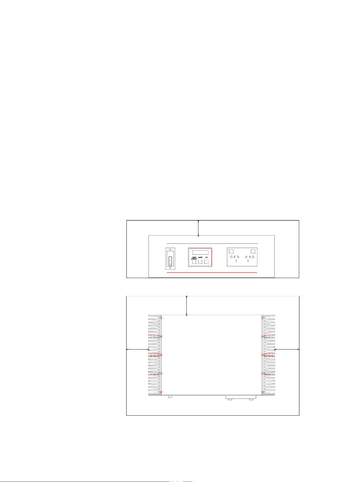
The inverter must be installed in a
dry, cool, dust-free environment.
Please leave at least 300mm
clearance at the left and right hand
sides (Black heatsink fins),
300mm above the inverter and
approx. 200mm at the rear as this
will aid the natural cooling of the
inverter. The air vents on the
underside of the SA41 also need to
be kept clear of obstructions.
300mm
300mm
SELECTRONIC SINE WAVE INVERTER
WITH ENERGY MANAGEMENT SA41
DC TO MAI NS POWER PROUDLY DESIGNE D & MADE IN AUSTRALIA
200mm
300mm
Front
2
Page 3
y
b
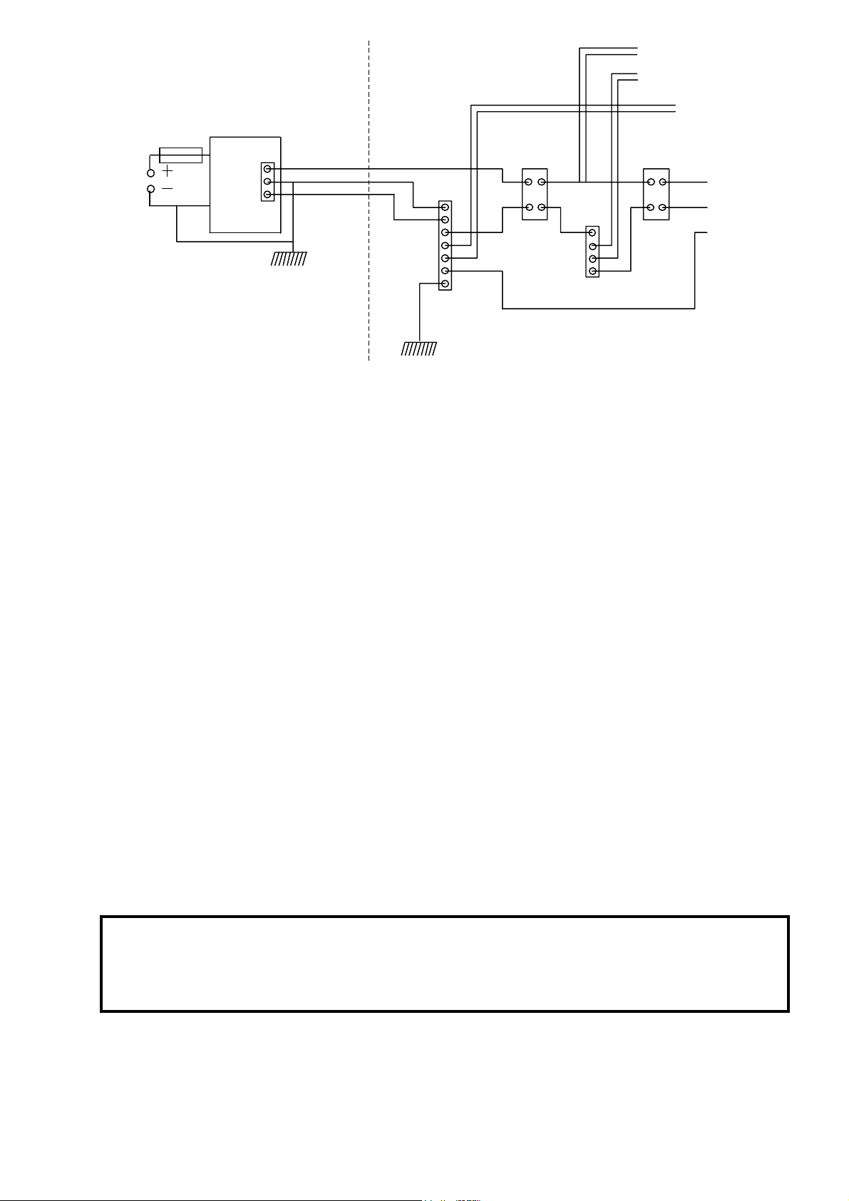
SUPPLY INSTALLATION
N
N
A
To circuit breakers
for other circuits
Earths
A
Power
Circuits
E
System Fuse
Batter
ank
Inverter
Rear
junction
Box
RFI / Lightning Earth
As close as possible to inverter
MUST BE BONDED TO
ALL OTHER EARTHS
Active
Earth
Neutral
GND
GND Safety Earth
Ground connection to
general mass of earth
E.L.C.B.
main switch
S1 S2
Neutral Link
ALL AC AND DC WIRING
MUST CONFORM TO
RELEVANT STANDARDS
Earth Le akage
Circuit Breaker
(E.L.C.B.)
We suggest that you house your inverter along with other power generating equipment in a remotely
sited purpose built area. Also make sure that the exhaust from your generator or other sources of heat or
fumes are kept well away from the SA41. SEIAA (Solar Energy Industries Association Of Australia)
installation guidelines must be followed.
You must have a suitable 48V DC battery bank which is maintained and operated to the battery
manufacturer’s recommendation. To ensure operation to SA41 specification, the battery bank should
have a minimum capacity of 500 ampere hours, at the 100 hour discharge rate (ask your supplier if in
doubt). Smaller capacity batteries can be used but may result in degraded performance of the SA41
under heavy surge conditions.
CONNECTION OF AC AND DC WIRING
IMPORTANT: Before making any wiring connections, check that the circuit breaker located on the
front panel is in the OFF position, i.e. LEVER DOWN.
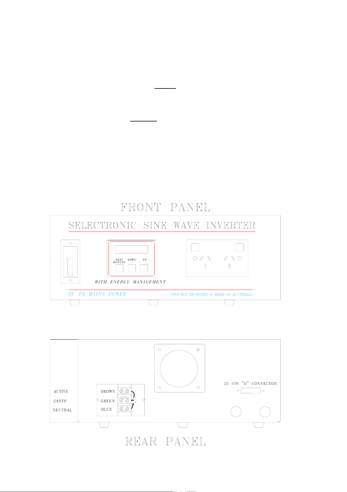
Your electrician should firstly connect the AC wiring via the three terminal rear junction box. Carefully
observe the correct connections. Please refer to the rear panel view of the SA41 on the following page.
BROWN ACTIVE (red dot, top connector)
GREEN/YELLOW EARTH (E, centre connector)
BLUE NEUTRAL (Bottom connector)
The lid of the junction box has knockouts to allow conduit entry. Make sure the connections are tight
and safe. Re-fit junction box cover.
NOTE:
ALL AC WIRING MUST BE CARRIED OUT BY A LICENSED ELECTRICIAN
AND MUST CONFORM TO AS 3000 WIRING REGULATIONS,
OR RELEVANT STANDARDS.
Verify that the circuit breaker on the front panel is in the OFF position, LEVER DOWN.
3
Page 4
Now connect the battery cables:
RED = BATTERY POSITIVE (+)
BLACK = BATTERY NEGATIVE (-)
These connections should be tight. If using nuts, bolts and washers, they should be stainless steel. At
this point re-check the connections before proceeding any further.
NOTE:
IF THE SA41 EMITS A PULSING BUZZER SOUND, THE BATTERY LEADS HAVE BEEN
CONNECTED IN REVERSE. IMMEDIATELY DISCONNECT THE LEADS AND RECONNECT
WITH THE CORRECT POLARITY. DO NOT UNDER ANY CIRCUMSTANCES TURN ON THE
BREAKER WHEN THE BUZZER IS PULSING AS PERMANENT DAMAGE TO THE SA41
WILL RESULT.
If all is well, turn the breaker ON, i.e. switch lever UP. If after two (2) attempts the circuit breaker does
not turn on, then check that the battery voltage is between 40 and 68V DC. If the breaker still won't
switch on, refer to the FAULT FINDING section of this manual.
4
Page 5

OPERATION
To gain more understanding of these operational notes, it is suggested that they be read in conjunction
with hands on access to an inverter with DC power applied.
When you first apply power to the SA41 with default factory settings, the SA41 should be in
STANDBY mode. There may be a quiet pulsing sound and the red neons on the power point will flash
if turned on. The SA41 is now ready for use with no further adjustments necessary, using the factory
settings.
If the display shows TIME, the default settings have been changed, and the day and time will need to
be set before the display will return to STATUS.
ENERGY MANAGEMENT
The SA41 incorporates ENERGY MANAGEMENT, which allows you to monitor and control your
energy system by displaying information on the Liquid Crystal Display. Settings can be adjusted via
the front panel keys.
STATUS
Status : STANDBY
Inverter : OFF
The first screen will display the Status of the SA41. There are three status conditions: STANDBY,
CONT (continuous) and RESET, which are explained in more detail below.
When this screen is displayed, the Status can be changed by pressing the UP or DOWN keys. Each time
the UP key is pressed, the status will change from STANDBY to CONT then RESET and back to
STANDBY whereas the DOWN key will change the Status in the reverse order.
The second line indicates whether the inverter is ON or OFF, i.e. if there is 240V available or not.
During pulsing, OFF is displayed on the second line, reverting to ON when a load is connected and the
inverter starts.
Status : CONT
Inverter : ON
Status : RESET
Inverter : OFF
The STANDBY mode means that the SA41 is producing pulses of power while waiting for an
appliance to be switched on. This is frequently called the “demand start” because as soon as the
appliance is operated, the SA41 will turn on and remain on until the appliance is switched off. After a
10 second delay, the SA41 will return to STANDBY mode, awaiting another load.
This feature is extremely important as it conserves valuable battery power when no appliances are on.
CONT mode (continuous) means the inverter will be on at all times regardless of the load. This
situation is useful if you have small loads such as VCRs or digital clocks that require 24 hour power, or
if loads are too small to be sensed in the STANDBY mode. The only disadvantage is that when no
appliances are operating, the SA41 will be drawing more power than it would in STANDBY mode.
RESET mode electronically shuts down the inverter. When placed in this mode, any overload or
shutdown conditions are also reset.
5
Page 6
READINGS
The SA41 ENERGY MANAGEMENT has six "Readings" displays to give you vital information
about your inverter and your batteries. By pressing the 'NEXT DISPLAY' key on the front panel, the
screen information rotates through displays of inverter Status, Time, AC Volts, AC Amps and Battery
Volts. When the optional current shunt (SA-S200) is installed, four additional readings are available;
these being Nett DC Current, Peak Charge Current, Nett Daily Amp Hours and Battery percentage
Charge.
TIME
Mon : 15:06
- - - Readings - - -
AC VOLTS
AC Volts : 240V
- - - Readings - - -
AC AMPS
AC Amps : 2.5A
- - - Readings - - -
BATTERY VOLTS
Displays the Current Time (as a 24Hr clock) and day. This time is set as
described in "Settings" (see Page 8).
This screen gives an approximate indication of the AC voltage produced by
the inverter. The AC volts would normally read between 230V and 245V
except under high load or low battery conditions.
The AC current reading shows the total current drawn from the AC output
by the appliances connected to the inverter.
Batt Volts : 49.2V
- - - Readings - - -
Displays the DC Battery volts. This provides you with an indication of the
condition of your battery bank.
WHERE THE OPTIONAL 200 AMP CURRENT SHUNT IS INSTALLED:
DC CURRENT
Amps : 23.6A OUT
- - - Battery - - -
PEAK AMPS
Pk Amps : 45.6 IN
- - - Battery - - -
This reading gives a Nett current; i.e., either charging the battery (IN) or
being taken out of the battery (OUT). The range for this reading is 0-100A
IN and 0-200A OUT continuous or 0-400A OUT intermittent.
This reading gives the peak Nett charging current into the batteries for the
present day (today). If no load has been present for the entire day, this will
indicate the peak combined charging current from your solar panels, wind
generator or other charging sources, thus allowing you to monitor their
operation. During the first day after the inverter is turned on at the circuit
breaker, this screen will display a meaningless figure.
6
Page 7
NETT AMP HOURS TODAY
Net AH : 69 IN
- - - Today - - -
BATTERY CHARGE
Charge : 87%
- - - In Battery - - -
This reading gives a nett figure of Amp Hours since midnight last night. A
nett AH reading of IN indicates more Amp Hours have gone into the
battery than have been used. The opposite applies for a Net AH reading of
OUT.
1 Amp Hour = 1 amp for 1 hour, or 2 amps for ½ hour, etc.
This reading shows the amount of charge present in you battery bank at any
given time. i.e. 100% means a fully charged battery.
MINIMUM CHARGE
With the optional current shunt (SA-S200) installed, the minimum charge in your batteries today, this
week or for a number of weeks or days can be logged (Minimum daily discharge). Minimum charge
readings are accessed by pressing the UP and DOWN keys together for 1 second.
These vital readings give you the information you need to maximise your battery life. This is done by
managing your loads to maximise this figure, e.g. using heavier loads later in the day or at other times
when the battery charge is high.
MINIMUM CHARGE TODAY
MIN CHARGE : 76%
- - - In Batt Today - - -
MINIMUM CHARGE THIS WEEK
MIN CHARGE : 76%
- - - In Batt This Wk - - -
MINIMUM CHARGE WEEKLY LOG
Weeks ago : 1
Min Charge : 76%
The minimum charge in the battery since midnight last.
The minimum charge in the battery since midnight last Saturday.
This displays a log of the minimum weekly charge in the battery for up to
52 weeks. The logged weeks may be stepped through by pressing the UP or
DOWN key. The weeks that have not logged AH as yet will display 255%.
MINIMUM CHARGE DAILY LOG
Days ago : 1
Min Charge : 76%
This displays a log of minimum daily charge in the battery for up to 30
days. The logged days may be stepped though by pressing the UP or
DOWN key. The days that have not logged AH as yet will display 255%.
7
Page 8
SETTINGS
There are a number of settings within the SA41 that can be changed via the front panel push keys (push
buttons). These allow you to tailor the SA41 inverter and ENERGY MANAGEMENT sections to suit
your system requirements.
Settings are accessed by holding down the NEXT DISPLAY key for at least 1 second whilst in any
"Readings" display. The value of the parameter displayed can be modified by pressing the UP or
DOWN keys.
Pressing the NEXT DISPLAY key will take you to the next parameter to be set. Pressing the NEXT
DISPLAY key after the last parameter is displayed will take you back to the "Readings" displays.
Please note: If DC power is disconnected from the inverter, the "Settings" which have been entered
will be saved and held in permanent memory. However these settings are not saved until the display is
returned to "Readings".
CONTROLLER OUTPUTS
The SA41 ENERGY MANAGEMENT has 2 control outputs, as mentioned on page 25, each of
which can be activated with time, inverter cutout and/or low ampere-hours. The six settings are
displayed as OFF, ON, TIME, INV CO, LO A/H and CO+LAH respectively
For simplicity, the displays shown are for control output 1 only. Control output 2 settings are identical
to control output 1. Pressing the UP or DOWN keys will change the setting.
On with : OFF
[Set Control 1]
On with : ON
[Set Control 1]
On with : TIME
[Set Control 1]
The control 1 output will remain off at all times.
The control 1 output will remain on at all times.
The control 1 output will come on at the Start Day, Start Hour and Start
Minute that is set in the three screens below.
The Start Day can be set to ALL which will turn the output on every day
at the set time. Pressing the UP or DOWN keys will change the setting.
The output will remain on for the time set in "Duration". (see next page)
Start Day : SUN
[Set Control 1]
Start Hour : 16
[Set Control 1]
8
Start Min : 30
[Set Control 1]
Page 9
On with : INV CO
[Set Control 1]
(Inverter Cut out) The control 1 output will turn on when the inverter shuts
down due to overload, over temperature or low or high voltage.
The output will remain on for the time set in "Duration", below.
The output will not come on if the front panel circuit beaker is tripped.
On with : LO A/H
[Set Control 1]
On with : CO+LAH
[Set Control 1]
Note that the controller can only be set to LO A/H and CO+LAH if the optional external current shunt
kit (SA-S200) is used. Each controller output is capable of switching an external relay or contactor
which can be used to switch AC or DC loads.
If the controller is set to INV CO, LO A/H or CO+LAH and the condition still exists after the
"Duration" time, the output will stay on until the condition ends. Also with these settings a "Lockout"
option can be set ON or OFF. (See lockout below and on page 11)
(Low Amp-Hours) If the charge in the batteries falls below the level set in
the "Minimum Charge" setting (see page 13), then the control output will
come on, for the time set in "Duration", below.
(Cutout or Low Amp-Hours) This setting combines the previous two, bring
the output on with low amp hours, or with the inverter cutting out.
The output will stay on for the time set in "Duration", below.
LOCKOUT
Lockout: ON
[Set Control 1]
DURATION
Duration : 4 Hrs
[Set Control 1]
Duration : 30 Min
[Set Control 1]
If set to ON, lockout prevents the controller output coming on during the
lockout period. (See notes on lockout on page 11.) Pressing the UP or
DOWN keys will change the setting.
This screen sets the duration hours the control 1 output will stay on.
Pressing the UP or DOWN keys will change the setting.
This screen sets the duration minutes the control 1 output will stay on.
Pressing the UP or DOWN keys will change the setting.
9
Page 10

BUZZER ON / OFF
Buzzer : ON
[Set Parameters]
BUZZER LOCKOUT
Buzzer Lockout : OFF
[Set Parameters]
MORE SETTINGS
Any key to end
or DOWN for more
SET DAY
This display allows you to select whether the audio alarm sounds during an
overload or other alarm conditions. If set to OFF the buzzer will not sound
during an alarm condition. The alarm condition will still be displayed.
Pressing the UP or DOWN keys will change the setting.
If set to ON, lockout prevents the buzzer from sounding during the lockout
period. See lockout on page 11. Pressing the UP or DOWN keys will
change the setting.
Pressing NEXT DISPLAY or UP keys will save the settings entered and go
back to ‘Displays’. If the DOWN key is pressed, more settings will be
displayed.
Day : MON
[Set Parameters]
SET HOUR (TIME OF DAY)
Hour : 15
[Set Parameters]
SET MINUTE (TIME OF DAY)
Minute : 30
[Set Parameters]
DEMAND START SENSE
Sets the current Day. Use the UP and DOWN keys to set the value.
Set the hours in the current time of day (24 hour time). Use the UP or
DOWN keys to set the value.
Sets the minutes in the current time of day. Use the UP or DOWN keys to
set the value.
DS Sense : 6W
[Set Parameters]
This sets the minimum load which will bring the SA41 ON when the
inverter Status is set to STANDBY mode (demand start or pulsing). See
page 5. In most cases the default setting of 6W would be suitable. If there is
a load which the SA41 won't sense then reduce this value until the SA41
starts. Alternatively if there is a small load that keeps the SA41 on then
increase this value. You may need to try a few different settings to find the
most appropriate value for your installation. Use the UP or DOWN keys to
set the value.
10
Page 11

LOCKOUT
Lockout is a feature which ensures that you are not disturbed during a specified period of time, e.g.
you do not want to start a generator in the middle of the night. When set to ON, lockout prevents
the controller outputs coming on, or the buzzer sounding during the lockout period.
The lockout start and finish times below affect both controller lockout, and buzzer lockout. (See
Buzzer Lockout on page 10.) Buzzer lockout and controller lockout may be set ON or OFF
individually.
SET LOCKOUT START TIME
Lockout on : 22:00
[Set Parameters]
SET LOCKOUT FINISH TIME
L’out off : 6:00
[Set Parameters]
LOW VOLTAGE TRIP
Lo Volt Trip : YES
[Set Parameters]
LOW DC VOLTS CUTOUT
This is the time the lockout for the controllers and buzzer commences.
After this time, the buzzer will not sound and the controlled outputs will not
come on. If a control output is already on, lockout will not turn it off. Use
the UP or DOWN keys to set the time.
This is the time the lockout for the controllers and buzzer ends. Use the UP
or DOWN keys to set the time.
When set to YES, the circuit breaker on the front panel will trip to
completely disconnect the inverter from the batteries when the DC battery
volts remains below the ‘Lo DC Volts’ setting (described below) for more
than 2 minutes. Use the UP or DOWN keys to change the setting.
Lo DC Volts : 40.0
[Set Parameters]
LOW DC VOLTS ON
Lo DCV on : 48.0
[Set Parameters]
HIGH DC VOLTS CUTOUT
Hi DC Volts : 68.0
[Set Parameters]
The SA41 will cut out (not tripping the breaker) and a message displayed if
the battery voltage falls below this setting for more than 10 seconds,
regardless of the setting of ‘Lo Volt Trip’. The inverter will restart if reset
or when the battery volts rise above the ‘Lo DCV On’ setting (next
setting).
Please note that if the battery volts drop below 35V (regardless of the ‘Lo
DC Volts’ setting) then the breaker will trip instantly, disconnecting the
The SA41 will restart after a Low Battery Volts cut-out when the battery
volts rise above this setting. Use the UP or DOWN keys to set the value.
When the battery volts exceeds this setting, the SA41 will cut out
instantaneously. Please note that if the battery volts rise above 70V
(regardless of the ‘Hi DC Volts’ setting), the breaker will instantly trip and
the inverter will be totally disconnected.
11
Page 12

AC VOLTS SETTING
AC Volts : 240V
[Set Parameters]
ALARM INPUTS
The ENERGY MANAGEMENT has 2 alarm inputs (shown on pages 25 and 26) which can be set to
trigger an alarm condition. (See page 15).
Use the ‘Lo’ setting if the input is connected to a normally closed set of contacts (see fig 2.1 on page
26), of when the voltage falls below 1V on alarm (see fig. 2.4).
Use the ‘Hi’ setting if the input is connected to a normally open set of contacts (see fig. 2.2 on page 26),
or when the voltage rises above 3V on alarm (see fig. 2.3).
ALARM INPUT 1
Alarm 1 active : Hi
[Set Parameters]
Allows the output voltage to be set from 220V to 240V if an output voltage
other than 240V is required. Use the UP or DOWN keys to set the value.
NZ users should set this to 220VAC.
Set alarm input 1 to HI or LO active. Use the UP or DOWN keys to change
the setting.
ALARM INPUT 2
Alarm 2 active : Hi
[Set Parameters]
EXTERNAL KEYPAD
Ext. Keypad : YES
[Set Parameters]
CURRENT SHUNT SETTINGS
EXTERNAL SHUNT
Ext. Shunt : YES
[Set Parameters]
Set alarm input 2 to HI or LO active.
This is set to YES if an optional external keypad (SA-KP-01) is connected.
Otherwise this is set to NO. See page 27. Use the UP or DOWN keys to
change the setting.
This is set to YES if an optional external current shunt (SA-S200) is
connected. Otherwise this is set to NO. See page 28. Use the UP or DOWN
keys to change the setting.
If the current shunt is set to YES the following settings will be displayed.
12
Page 13

ZERO DC AMP READING
Zero DC Amps : OFF
[Set Parameters]
BATTERY CAPACITY
Capacity : 500AH
[Set Parameters]
CHARGE IN BATTERY
AH IN Batt : 445
[Set Parameters]
MINIMUM CHARGE IN BATTERY
This setting is used to zero the current reading from the external current
shunt. See installation notes in Appendix III on page 28. Use the UP or
DOWN keys to change the setting. Note: when this setting is set to ON, a
zero DC amps is performed taking about 1 to 2 seconds, after which the
display returns to OFF.
This is the capacity of the batteries in ampere-hours at the system discharge
rate. For example, a solar powered system will generally use the C/100
(100 hour rate), but a diesel recharge system may use a discharge rate of
C/20 (20 hour rate). Your system designer will advise you on this figure.
Use the UP or DOWN keys to set your battery capacity.
This setting is used at setup to enter the initial charge in the battery in
Ampere Hours, or during use to bring the readings back in line. Use the UP
or DOWN keys to set the value.
Min Charge : 60%
[Set Parameters]
LOW CHARGE ALARM
Lo Chg Alarm : OFF
[Set Parameters]
BATTERY CHARGE EFFICIENCY
Batt Effic. : 95%
[Set Parameters]
END SETTINGS
If the charge in the battery bank drops below this level, an alarm will sound
if the low charge alarm (the next setting) is set ON. Use the UP or DOWN
keys to set the value.
If set to ON, an alarm will sound if the charge in the batteries drops below
the Min Charge setting above. Use the UP or DOWN keys to change the
setting.
This setting is determined by the system design and the type and age of the
batteries used. If the battery efficiency is unknown, then we suggest that
you use the default setting of 95% initially, and adjust if the ampere-hours
in the batteries differs from the readings.
End Settings
[Set Parameters]
Press NEXT DISPLAY key to return to "Readings".
13
Page 14

OVERLOAD SHUTDOWN AND ALARMS
The SA41 has eight alarm and overload conditions. These result from high or low battery volts, high
AC volts, AC output overloaded, transformer too hot, heatsink too hot, either of the two alarm inputs
being active, or low battery charge. If any of these conditions occur, a message will be displayed. If
there is more than one alarm condition the display will alternate between messages.
The alarm message will remain on the display until a key is pressed, even if the alarm condition ends.
(i.e. after a high voltage condition the battery volts comes back down again) This allows you to
determine the cause of the shutdown even if the inverter comes on again before you are able to read the
display. To reset the inverter after it has shutdown, set the inverter Status to RESET, and then back to
STANDBY. (See page 5.)
DC VOLTS HIGH
Hi DC Volts : 66.0
* * Press a Key * *
DC VOLTS LOW
Lo DC Volts : 38.0
* * Press a Key * *
AC VOLTS HIGH
AC Volts Hi : 0
* * Press a Key * *
INVERTER OVERLOAD
This message is displayed and the inverter shuts down if the battery voltage
rises above the ‘Hi DC Volts’ setting. The inverter will automatically
restart when the battery voltage drops below this value. The present battery
voltage is also displayed.
This message is displayed and the inverter shuts down if the battery voltage
drops below the ‘Lo DC Volts’ setting for more than 10 seconds. The
inverter will automatically come on again when the battery voltage rises
above the ‘Lo DCV ON’ voltage or if the inverter is manually reset (via the
STATUS display, see page 5). The present battery voltage is also displayed.
If a system fault causes the AC voltage to go too high, then this message is
displayed.
Inverter O/L : 0
* * Press a Key * *
TRANSFORMER TOO HOT
TX Too Hot : 122C
* * Press a Key * *
An AC current overload or a short circuit on the AC output will cause the
inverter to shut down and display this message. If the shutdown was due to
an overload, the SA41 will automatically reset after 1 minute, or when a
key is pressed. If the shutdown was due to a short circuit, the SA41 will
have to be reset (via the STATUS display, see page 5) on the front panel.
If the transformer reaches its maximum operating temperature, the SA41
will shut down to protect the internal components. The SA41 will restart
again only when the temperature drops to a safe level. The present
temperature of the transformer is also displayed.
14
Page 15

HEATSINK TOO HOT
b
HS Too Hot : 82C
* * Press a Key * *
ALARM 1 ACTIVE
Alarm 1 Active :
* * Press a Key * *
ALARM 2 ACTIVE
Alarm 2 Active :
* * Press a Key * *
LOW CHARGE ALARM
If the heatsink reaches its maximum operating temperature, the SA41 will
shut down to protect itself. The SA41 will come on again only when the
temperature drops to a safe level. The present temperature of the heatsink is
also displayed.
When the Alarm 1 input on the SA41 is activated, (see "Settings" on page
12) this message is displayed and the buzzer sounds. The buzzer will
continue to sound as long as the input is active.
When the Alarm 2 input on the SA41 is activated, (see "Settings" on page
12) this message is displayed and the buzzer sounds. The buzzer will
continue to sound as long as the input is active.
Lo Charge : 59%
* * Press a Key * *
If the battery charge drops below the ‘Min charge’ setting, and the ‘Lo
Chg alarm’ setting is set to ‘ON’ then this alarm will sound. You are then
able to take appropriate action such as removing loads or starting a
generator to prevent further discharge and possible damage to your
atteries.
FAULT FINDING
1. INVERTER STAYS ON EVEN WHEN NO APPLIANCE IS BEING USED.
This can be a common problem known as a "phantom load", but can be easily overcome with
ENERGY MANAGEMENT. Some appliances will need to be switched off at the power point as they
may still represent a small load despite being switched off at the appliance. Check again to make sure
there are no appliances left on, then sequentially switch off appliances at the wall and by watching your
night light (as described in "Handy Hint" on page 19), check to see if the SA41 returns to pulsing
mode (after a 10 second delay). Once you have found the offending appliance, adjust the sensitivity of
the demand start up (see set parameters) until the inverter turns off. Once this is done re check that
small loads will still bring the inverter on when required.
2. INVERTER WILL NOT COME ON WHEN SMALL APPLIANCE IS SWITCHED ON.
This means that your demand start sensitivity is set too high. With the appliance in question switched
on, adjust the demand start sensitivity until your SA41 turns on. See Demand Start Sense on page 10.
15
Page 16

3. INVERTER SHUTS DOWN DURING MIDDLE OF THE DAY, AND COMES BACK ON
LATE IN THE AFTERNOON.
This is more than likely caused by high battery volts during peak charging times from solar panels. To
overcome this, adjust the high voltage cutout of your SA41 (see High DC Volts Cutout on page 11); the
maximum voltage allowable being 34 Volts. If this is still not high enough you may have a problem
with either your batteries or your regulator. This could be potentially dangerous so we advise you to
consult your system designer immediately.
4. INVERTER SHUTS DOWN WITH LOW VOLTS.
If your SA41 has shut down because of low DC volts it could be due to the following:
(1) A sustained large load could be causing the battery volts to drop to a low enough point to cause
the SA41 to cut out. This is not normally a fault with the SA41 but could be due to the following:
(a) Battery bank is too small - consult your system designer.
(b) A bad connection between the batteries and inverter due to a loose or corroded terminal.
In this case, please refer to the maintenance section of this manual.
(c) One or more battery cells could be faulty - consult your installer.
(2) If your battery volts are below 47V with no loads connected, the batteries may require charging.
Use a hydrometer to check the specific gravity of each cell. Consult your battery manual for the
correct specific gravity (SG) readings.
5. INVERTER SHUTS DOWN DUE TO HEATSINK TOO HOT
This is likely under heavy sustained load conditions since the SA41 shuts down to protect its internal
components. If you believe that the load is not excessive, check around the inverter case and heatsinks
for obstructions to air flow as this will cause the inverter to heat up much quicker and shut down sooner
than normal. Also check that the clearances around the SA41 are as specified in INSTALLATION on
page 2.
6. “CHARGE IN BATTERY” APPEARS INCORRECT
It is possible that this figure can accumulate errors, as battery charging / discharging is a very complex
procedure with many variances; a hydrometer is always the most accurate method of determining a
battery’s state of charge. If your system regulator is showing FLOAT then you should be able to
presume your batteries are close to, or actually, 100% charged. You can confirm this with a
hydrometer. If the “CHARGE IN BATTERY” figure is not reading correctly, adjust it by the method
shown in page 13. If the figure is consistently too low, (e.g. 90% when the system shows FLOAT) you
should increase the battery charge efficiency figure as described in page 13. Alternatively, if your
system is not in float and the reading is already 100%, you should reduce the battery efficiency.
7. INVERTER PULSES SLOWER THAN NORMAL WHEN IN STAND-BY
This means that the inverter has not been switched on for approximately 20 minutes and has gone into a
power saving mode, thus pulsing at about half the normal rate.
8. “NETT AMP HOUR” APPEARS INCORRECT
This could be caused by one or both of the following:
(a) The clock is not adjusted correctly, see page 8.
(b) The “DC Amps” reading is not correct. Adjust this by zeroing the meter, see pages 13 and 28.
16
Page 17

SYSTEM MAINTENANCE
To get the optimum performance from your SA41 power inverter, particularly under heavy appliance
loads, it is essential that the battery bank and the DC wiring are all in good condition. The small amount
of time spent on the suggested maintenance tasks that follow will maximise the reliability of your
system.
SA41 MAINTENANCE
Periodic maintenance of the SA41 inverter involves little more than checking for unobstructed
operation of the cooling fan, which is located at the rear of the inverter. Note that cooling air is drawn in
through vents underneath the inverter.
Suggested inverter maintenance should include:
1. Check for unobstructed fan operation. Clear away any dust or foreign matter from the fan grill
using a soft bristled brush. (Do not direct high pressure compressed air at the fan blades)
Note that the fan is designed to come on during heavy power demand.
2. Check between fins of the heatsinks and clean out any accumulated foreign objects, for example,
insect nests.
3. Verify that the air flow beneath the chassis is not restricted.
4. Clean external surfaces of the SA41 using a soft, lint free cloth, with polish and wax. e.g. Mr.
Sheen.
BATTERY MAINTENANCE
1. Every week, carry out a thorough visual inspection of all battery wiring, taking particular note of the
condition of inter-connections between cells.
IMPORTANT:
When working on batteries of such high capacity, it is essential that you wear protective clothing,
some form of eye protection and rubber-soled work boots. Please regard your batteries with a
great deal of caution, and if in any doubt, entrust this work to your installer.
2. Check that the stainless steel inter-connecting bolts are tight and have minimal corrosion. If
corrosion is evident, carefully follow the following procedure.
(a) Disconnect the system battery fuse before working on the battery bank.
(b) Unbolt the stainless steel bolts and nuts of any corroded connections and thoroughly clean the
join with a wire brush or file, taking extreme care not to short circuit any battery cells with any
tools.
(c) Re-assemble and smear a small amount of Vaseline or similar grease over the surface of the
joint to slow down any future corrosion.
3. Every month: measure the specific gravity (SG) of each cell using your hydrometer, to ensure that all
cells are performing correctly. Any serious imbalance should be reported to your system designer in
case remedial action needs to be taken.
17
Page 18

SA41 ELECTRICAL SPECIFICATIONS
INVERTER TYPE PWM Full bridge power stage, with true sine wave AC output.
DEMAND START SECTION
Type: Pulsing AC
Minimum Load Power to start (User adjustable): 3W to 20W
Maximum response time: 1 sec
Standby current from battery (Average): 60mA
BATTERY VOLTAGE RANGE
Low DC Volts Disconnect (Instantaneous): 34V
Low DC Volts Cutout (Delayed, User Adjustable): 38-44V
Low DC Volts Cut-in (Delayed, User Adjustable): 44.4-52V
High DC Volts Cutout (Instantaneous, User Adjustable): 60-68V
High DC Volts Disconnect (Instantaneous): 70V
TOTAL APPLIANCE RATING AT 25°C 40°C
Continuous: 3000W 2800W
30 Minute rating: 4700W 4400W
5 Minute rating: 5300W
1 Minute rating: 6500W
Surge rating: 8500W
INVERTER EFFICIENCY
Peak (at 500W): 91%
No load power consumption (C0NT mode): 0.66 A
MISCELLANEOUS SPECIFICATIONS
Output Frequency Accuracy: 50Hz ± 0.001 %
Output Voltage Accuracy (0 - 2200W) 240V ± 4 %
Total Harmonic Distortion (THD) < 4 %
Control Outputs 1 & 2, max DC sinking current: 50 mA
Alarm Inputs 1 & 2, input switching level: HI > 3 V
LO < 1 V
Operating temperature range: -10°C to 50°C
Weight: 32 kg
DC Input is Electrically Isolated from AC Output
Note: Through a policy of continued development, specifications are subject to change without
notice.
The above specifications are based on unity power factor.
18
Page 19

RADIO FREQUENCY INTERFERENCE
For many years, Radio Frequency Interference (RFI) has been an annoying problem for owners of
Inverters. RFI in a domestic situation causes noise or interference on a radio or TV receiver. Most of
the problems with RFI in a Remote Area Power Supply (RAPS) installation involve AM radio
reception.
Considerable development time has resulted in a reduction of the RFI produced by the SA41 to a level
that complies with Australian Standard AS1044. Compliance to this standard means RFI is low but
how well the inverter performs in a particular installation can vary. Below are some suggestions to help
reduce the effects of RFI in your installation.
It is recommended that the power system including the inverter is housed at least 15 metres from the
home.
Ensure a good earth stake is placed as close to the inverter as possible. See installation on page 3 for
wiring.
Avoid running DC wiring into the home, if at all possible. If this cannot be avoided, run DC and AC in
separate conduits separated by as much distance as practicable. All DC wiring should also be kept as
short as possible.
To further reduce the effects of RFI, it is important that your AM radio has good signal strength. This
will enable your radio to reject any noise being produced by your inverter, regulator, controllers or DC
lighting. If possible, try moving the radio around to improve signal strength or use an external aerial.
Some of today's building materials such as steel roofs and foil insulation may form a barrier to
incoming radio signals. If an external aerial is required, it should be on the outside of the home,
mounted as high as practicable and as far from the battery shed as possible. Connection from the aerial
to the radio should be via a low loss coaxial cable.
PLEASE NOTE: The aerial must be an AM RADIO type. A TV aerial will not work.
HANDY HINT
It is very important that you become familiar with the functioning of your inverter. Since most Inverters
are remotely sited from the home, it is not always easy to know if the inverter is ON or pulsing. An easy
way to determine this is to plug a small child's night light (neon type) into a power point which is easily
visible, or replace the power point with a safety type with a neon indicator. This will indicate the
inverter's operation by flashing when the inverter is pulsing and remaining on when the inverter is
brought on by a load.
19
Page 20

APPENDIX I: DIAGNOSTICS
The "Diagnostics" is a special set of displays that give additional information about the SA41. These
are normally only used when advanced troubleshooting is undertaken. The "Diagnostics" section
displays the transformer and heatsink temperature, demand start current and software version
information.
"Diagnostics" is accessed by holding both UP and DOWN buttons together twice, for at least 1 second
each time, during the display of any "Readings" screen with the exception of "Status". The NEXT
DISPLAY key takes you through the "Diagnostics" displays, eventually returning to the "Readings"
display. See page 22 for more information.
TRANSFORMER TEMPERATURE
TX Temp : 75C
* * Diagnostics * *
HEATSINK TEMPERATURE
HS1 Temp : 34C
* * Diagnostics * *
HS2 Temp : 34C
* * Diagnostics * *
DEMAND START CURRENT
D/S Current : 48
* * Diagnostics * *
This display is the operating temperature of the transformer inside the SA41
in degrees Celsius.
This displays the operating temperature of the left heatsink.
This displays the operating temperature of the right heatsink.
This gives a reading of the value read by the demand start sense circuit and
can be useful during advanced demand start troubleshooting.
SOFTWARE VERSION
SELECTRONIC C
SA41 1.00 1996
This displays the revision of the software running your SA41.
Please note that this software is Copyright to SELECTRONIC
AUSTRALIA P/L and it is an offence to copy or duplicate any part of this
program. This is the last screen in the "Diagnostics" and pressing the NEXT
DISPLAY key once more will return you to the readings.
20
Page 21

APPENDIX II: FLOW DIAGRAM FOR DISPLAYS AND SETTINGS
READINGS
Status: STANDBY
Inverter: OFF
MON: 15:06
---Readings---
AC Volts: 240V
---Readings---
AC Amps: 2.5A
---Readings---
Batt Volts: 49.2V
---Readings---
Amps: 23.6A OUT
---Battery---
Pk Amps: 45.6 IN
---Battery---
Net AH: 69 IN
---Today---
Charge: 87%
--In Battery--
Current Shunt
Not Installed
21
Page 22

MINIMUM CHARGE DISPLAY
Access to the next 5 screens is from the “Readings” screen.
Hold the “Down” and “Up” keys simultaneously for approximately 1 second, then release the keys.
Min Charge: 67%
In Batt Today
Min Charge: 67%
In Batt This Wk
Weeks go: 1
Min Charge: 76%
Days ago: 1
Min Charge: 76%
End Min Charge
Back to "Readings"
SWITCHING BETWEEN READINGS, MINIMUM CHARGE, AND DIAGNOSTICS
Readings
Press UP and Down together
for 1 second
Minimum charge
displays
Press UP and Down together
for 1 second
Diagnostic
Displays
Pressing NEXT DISPLAY
will return to Readings
22
Page 23

SETTINGS
Access is from “Readings” screen.
Hold down “Next Display” key for approximately 1 second.
ON or OFF
On with: TIME
[Set Control 1]
Start Day: SUN
[Set Control 1]
Start Hour: 16
[Set Control 1]
Start Min: 30
[Set Control 1]
Duration: 4 Hrs
[Set Control 1]
Duration: 30 Min
[Set Control 1]
INV CO, LO A/H or
CO+LAH
Lockout: ON
[Set Control 1]
CONTROL OUTPUT 2
SET AS FOR OUTPUT 1
Buzzer: ON
[Set Parameters]
Buzz Lockout: OFF
[Set Parameters]
DS Sense: 6W
[Set Parameters]
Any key to end
or DOWN for more
Day: MON
[Set Parameters]
Hour: 15
[Set Parameters]
Back to
"Readings"
if DOWN
not pressed.
Minute: 30
[Set Parameters]
Continue on to next page
23
Page 24

From previous page
Lockout on: 22:00
[Set Parameters]
L'out off: 6:00
[Set Parameters]
Lo Volt Trip: YES
[Set Parameters]
Lo DC Volts: 40.0
[Set Parameters]
Lo DCV on: 48.0
[Set Parameters]
Hi DC Volts: 68.0
[Set Parameters]
AC Volts: 240V
[Set Parameters]
Alarm1 active:HI
[Set Parameters]
Alarm2 active:HI
[Set Parameters]
Ext. Keypad: YES
[Set Parameters]
Zero DC Amps:OFF
[Set Parameters]
Capacity: 500AH
[Set Parameters]
AH In Batt: 445
[Set Parameters]
Min Charge: 60%
[Set Parameters]
Lo Chg Alarm:OFF
[Set Parameters]
Batt Effic.:95%
[Set Parameters]
End Settings
[Set Parameters]
Ext. Shunt: YES
[Set Parameters]
Back to "Readings"
if no Current Shunt
YES
Back to "Readings"
24
Page 25

APPENDIX III: SA INVERTER OPTIONS
GENERAL
The SA41 employs a rear chassis-mounted 25-pin connector, which allows you to add a selection of
optional features to your power system. Note that the software for these functions is already
installed within the SA41 microcontroller.
The full range of features are:
(a) Remote Keypad: A low profile keypad with 2-line Liquid Crystal Display, which can
be located up to 500 metres from your SA41.
Wiring requirements - 6 conductor shielded cable.
(b) DC Current Shunt: Consists of a 200 Amp 75mV current shunt, mounted on an insulated
base, and a twin flex loom for current sensing.
(c) Controller Outputs: Two external relay or contactor coils can be energised for various AC
or DC switching applications.
(d) Alarm Inputs: Two digital inputs that can be programmed to monitor switch contact
status or voltage levels (refer to following circuits for examples)
SA-SB-01 INTERFACE KIT
The Interface Kit SA-SB-01 plugs into the rear of the SA41 and provides a convenient termination
point for the various options outlined above. The screw terminals are numbered from 1 to 14 and
the connections are as follows:
TERMINAL NO DESCRIPTION
1 & 14 +48V with 1A internal fuse
2 Alarm input 2
3 Alarm input 1
4 0V
5 - 8 Keypad data lines
9 Keypad +12V
10 & 11 200A current shunt connections
12 Controller output 2
13 Controller output 1
Please refer also to Diagram 1 overleaf.
25
Page 26

SA-SB-01
(
)
INTERFACE BOARD
TOP VIEW
+48V (INT FUSE)
ALARM INPUTS
DB25-M
TO SA41 INVERTER
CONTROLLER
OUTPUTS
SA-SB-01 INTERFACE CONNECTIONS
REFER BELOW EXAMPLES
1
2
IN 2
3
IN 1
0V
4
5
DO-
D0+
6
7
RIN-
RIN+
8
9
+12V
10
INV-
11
BATT-
12
OUT 2
13
OUT 1
14
+48V
INVERTER -INVERTER -
CHARGER -
ALL CHARGING
AND DISCHARGING
SOURCES, NEG LEAD
FOR ALARM INPUT
APPLICATIONS,
BLK
GRN
BLU
WH
YELL
RED
SHIELD
50mA MAX
50mA MAX
1A FUSE INSIDE INVERTER
RELAY-SPDT
SA-S200
200 AMP 75mV
CURRENT SHUNT
+48V
RELAY-SPDT
-
48V
BATTERY
GROUND
REAR VIEW
5
6
+
SYSTEM
FUSE
SA-KP-01
KEYPAD
RED
1
BLK
2
YELL
3
WH
4
BLU
GRN
TO INVERTER POSITIVE
FUSE BATTERY NEGATIVE
IF IT IS NOT EARTHED
Figure 1
ALARM INPUTS - Examples
(Alarm input 1 shown only)
ALARM FITTED TO BATTERY ROOM DOOR
REED SWITCH
NORMALLY CLOSED
+48V
1
IN2
2
IN1
3
SET ALARM INPUT 1 = LO SET ALARM INPUT 1 = HI
+48V
IN2
IN1
1
2
3
Figure 2.2Figure 2.1
Figure 2
GENERATOR OIL PRESSURE MONITOR
+48V
1
LAMP
IN2
2
MONITORING OF SWITCH CLOSURE
WHERE ONE SIDE COMMITTED TO EARTH
+48V
1
IN2
2
NORMALLY OPEN
4.7K 2W
IN1
0V
3
OIL
PRESS
SWITCH
4
IN1
0V
3
4
SET ALARM INPUT 1 = HI
SET ALARM INPUT 1 = LO
Figure 2.4Figure 2.3
26
Page 27

INSTALLATION OF SA-KP-01 OPTIONAL KEYPAD
Installation of the optional keypad requires the interface board (SA-SB-01) plus a suitable
length of 6 conductor (3 pair) shielded 7 / 0.2 data cable.
1. Carefully unpack the Keypad Kit. The front cover has been left loose to
allow access to the 4 mounting holes as shown.
2. Prior to attaching the keypad to the wall, bulkhead, etc., complete the electrical connections to
the user screw connector as shown in Diagram 1 on page 26. Please take careful note of the
orientation. Plug the screw connector into the back of the keypad and secure the keypad chassis
in its intended location
3. Clip the grey plastic front cover over the chassis, applying firm
pressure at the points shown at right.
4. At the SA41 end of the shielded cable, connect the 6 wires to the SA-SB-01 Interface Board,
using screw terminals 4 to 9, as shown in Diagram 1. Connect the cable shield to the 0V terminal
(No. 4, Black) to reduce radiated electrical noise from the cable.
5. Ensure that the SA41 is switched off at the front panel circuit breaker.
6. Plug the SA-SB-01 Interface Board into the rear DB25 connector of the SA41.
7. Switch on the SA41 at the circuit breaker. The keypad will not display any information at this
stage.
8. Via the SA41 front panel, access the “Settings” menu as described in Page 8 of the manual.
Scroll slowly through the screens until the following display is seen:
Ext. Keypad: NO
[Set Parameters]
Select YES using the ”UP” key. Scroll through the remainder of the “Settings” screens until the
“Readings” screen is reached.
9. The external keypad will now display the same information as appears on the SA41 front panel.
27
Page 28

INSTALLATION OF SA-S200 OPTIONAL CURRENT SHUNT
Installation of the current shunt requires the SA-SB-01 interface board.
1. The 200 Amp 75mV precision current shunt must be fitted between the negative (black) lead of
the SA41 and battery negative, as shown on diagram 1. Please ensure that cables are kept as
short as possible. At least 120 Amp continuously rated battery cable should be used.
2. Attach the shunt and insulated base securely to a solid structure.
3. Using the twin flex supplied, wire up the current sensing wires to the SA-SB-01 Interface Board
as shown in Diagram 1, terminals 10 and 11 being used for the current sensing. Take careful
note of the polarity.
4. Ensure that the SA41 Status is in "RESET" mode, which ensures that the SA41 is not drawing
any DC current through the shunt. Also, disable all charging sources, such as Solar Panels and
wind generators.
5. Via the SA41 front panel, access the “Settings” menu as described on Page 8 of the manual.
Scroll slowly through the screens until the following display is seen:
Ext. Shunt: NO
Set Parameters]
Select YES using the ”UP” key.
6. Scroll to the next screen and the following display will be seen:
Zero DC Amps: OFF
[Set Parameters]
Select ON using the ”UP” key. Note: when this setting is set to ON, a zero DC amps is performed
taking about 1 to 2 seconds, after which the display returns to OFF.
Scroll through the remainder of the “Settings” screens until the “Readings” screen is reached.
7. Scroll through the “Readings” screen until the following screen is displayed:
Note that when the battery current is zero, the screen may flicker between IN and OUT; this is
quite normal.
Amps: 0.0A OUT
----Battery----
8. Apply an AC load to the inverter's output and verify that the DC current reading is "OUT".
If not, then reverse the sensing wires to the current shunt.
28
Page 29

WARNING
THE OUTPUT VOLTAGE FROM AN INVERTER IS AS LETHAL AS
LANDLINE POWER.
It is therefore absolutely necessary for your safety to ensure that all Remote Area
power installations meet and comply with the relevant provisions and requirements of
wiring standards.
It is imperative that you ensure that only Electrical contractors are permitted to install
any AC wiring in your system.
PRODUCT WARRANTY CONDITIONS
Selectronic Australia Pty Ltd warrants your SA41 inverter to be free from defects in
materials and workmanship under normal use and service, for two (2) years.
This warranty is applicable from the date of original purchase. All parts will be
replaced or repaired free of charge within this period. Travelling time for field service
personnel is not covered under this warranty. The unit shall be returned at no cost to
the owner, if no authorised field service personnel are available.
After you have completed our post-installation questionnaire, you will receive a
lifetime warranty, applicable to the original purchaser only.
The provision of this warranty shall not apply if the unit has been subject to misuse,
neglect, accidental damage, damage from external influences e.g. corrosion, used for a
purpose it is not intended, acts of God or has not been installed in accordance with the
manufacturers latest installation requirements. (Any installation updates will be mailed
to your last known address.) Lifetime warranty is dependant on the supply of raw
materials from suppliers, above and beyond Selectronic Australia’s legal obligation.
Freight charges to the point of purchase and the cost of any repairs resulting from
damages occurring during this freighting will be borne by the owner.
Any alterations or repairs by unauthorised parties will void your warranty.
To ensure fast efficient handling of any warranty claims, please complete and return
your reply paid warranty card within 30 days from date of purchase. If service is
required, please return your inverter in its original carton with proof of purchase and a
brief description of the fault, to your point of service or any of the following service
centres:
Selectronic Australia Burley TV Service Reid Technology Ltd RF Analysis
25 Holloway Drive 278 Edmondson Ave 3-5 Auburn Street Harness Cask Road
Bayswater Austral Takapuna Dorrigo
Victoria 3153 NSW 2171 North Shore City NSW 2453
Australia Australia Auckland NZ Australia
Ph: 03 9762 4822 Ph: 02 606-0279 Ph: 9 489-8100 Ph: 066 57 8003
Fax: 03 9762 9646 Fax: 9 489-8585 Fax: 066 57 8002
29
Page 30

MOUNTING TEMPLATE FOR SA-KP-01 KEYPAD
Use this template when marking and cutting holes in plasterboard, etc., for the SA-KP-01 keypad.
30
 Loading...