

Page 1
FormNo.3362-225RevA
Reelmaster
®
5210/5410/5510/5610
Two-WheelDriveTractionUnits
ModelNo.03660—SerialNo.290000001andUp
ModelNo.03670—SerialNo.290000001andUp
ModelNo.03680—SerialNo.290000001andUp
ModelNo.03690—SerialNo.290000001andUp
ModelNo.03691—SerialNo.290000001andUp
ToregisteryourproductordownloadanOperator'sManualorPartsCatalogatnocharge,gotowww.T oro.com.OriginalInstructions(EN)
Page 2

Warning
CALIFORNIA
Proposition65Warning
Dieselengineexhaustandsomeofits
constituentsareknowntotheStateof
Californiatocausecancer,birthdefects,
andotherreproductiveharm.
Important:Thisengineisnotequippedwitha
sparkarrestermufer.ItisaviolationofCalifornia
PublicResourceCodeSection4442touseoroperate
theengineonanyforest-covered,brush-covered,or
grass-coveredland.Otherstatesorfederalareas
mayhavesimilarlaws.
Introduction
Readthisinformationcarefullytolearnhowtooperate
andmaintainyourproductproperlyandtoavoidinjury
andproductdamage.Youareresponsibleforoperating
theproductproperlyandsafely.
YoumaycontactTorodirectlyatwww .Toro.comfor
productandaccessoryinformation,helpndinga
dealer,ortoregisteryourproduct.
Wheneveryouneedservice,genuineToroparts,or
additionalinformation,contactanAuthorizedService
DealerorToroCustomerServiceandhavethemodel
andserialnumbersofyourproductready.Themodel
andserialnumbersareonaplatemountedontheleft
sideoftheframeunderthefootrest.Writethenumbers
inthespaceprovided.
ModelNo.
SerialNo.
Thismanualidentiespotentialhazardsandhas
safetymessagesidentiedbythesafetyalertsymbol
(Figure1),whichsignalsahazardthatmaycauseserious
injuryordeathifyoudonotfollowtherecommended
precautions.
Figure1
1.Safetyalertsymbol
Thismanualuses2otherwordstohighlightinformation.
Importantcallsattentiontospecialmechanical
informationandNoteemphasizesgeneralinformation
worthyofspecialattention.
Contents
Introduction.................................................................2
Safety...........................................................................3
SafeOperatingPractices.......................................3
ToroRidingMowerSafety....................................5
SoundPressureLevel...........................................6
SoundPowerLevel...............................................6
VibrationLevel.....................................................6
SafetyandInstructionalDecals.............................7
Setup..........................................................................12
1AdjustingtheTirePressure..............................12
2AdjustingtheStepHeight................................12
3AdjustingtheControlArmPosition.................13
4InstallingtheCuttingUnits..............................13
5AdjustingtheTurfCompensation
Spring............................................................16
6InstallingRearWeights.....................................17
7InstallingtheCEHoodLatch...........................21
8UsingtheCuttingUnitKickstand.....................21
9UsingtheGaugeBar........................................22
10ReadingtheManualandViewingtheSafety
Video.............................................................22
ProductOverview......................................................23
Controls.............................................................23
Specications.....................................................26
Attachments/Accessories...................................26
Operation...................................................................27
CheckingtheEngineOilLevel............................27
CheckingtheCoolingSystem..............................28
AddingFuel.......................................................28
CheckingtheHydraulicFluid..............................30
CheckingtheReeltoBedknifeContact................31
ChecktheTorqueoftheWheelNuts...................31
BleedingtheFuelSystem....................................31
StartingandStoppingtheEngine........................32
SettingtheReelSpeed.........................................32
AdjustingtheLiftArmCounterbalance...............33
AdjustingtheLiftArmTurnAround
Position..........................................................34
PushingorTowingtheMachine..........................34
JackingPoints.....................................................35
TieDowns.........................................................35
UnderstandingtheDiagnosticLight....................35
DiagnosticAceDisplay.......................................36
CheckingtheInterlockSwitches.........................36
HydraulicValveSolenoidFunctions....................38
©2009—TheT oro®Company
8111LyndaleAvenueSouth
Bloomington,MN55420
Contactusatwww.Toro.com.
2
PrintedintheUSA.
AllRightsReserved
Page 3

OperatingTips...................................................38
Maintenance...............................................................39
RecommendedMaintenanceSchedule(s)................39
DailyMaintenanceChecklist...............................40
ServiceIntervalChart.........................................41
Lubrication.............................................................41
GreasingtheBearingsandBushings....................41
EngineMaintenance...............................................43
ServicingtheAirCleaner....................................43
ServicingtheEngineOilandFilter......................43
AdjustingtheThrottle........................................44
FuelSystemMaintenance.......................................45
DrainingtheFuelTank.......................................45
CheckingtheFuelLinesandConnections...........45
ServicingtheWaterSeparator.............................45
FuelPick-upTubeScreen...................................45
BleedingAirfromtheFuelInjectors...................45
ElectricalSystemMaintenance................................46
ServicingtheBattery...........................................46
Fuses..................................................................47
DriveSystemMaintenance.....................................47
AdjustingtheTractionDriveforNeutral.............47
AdjustingtheRearWheelToe-in.........................48
CoolingSystemMaintenance..................................49
RemovingDebrisfromtheCooling
System............................................................49
BrakeMaintenance.................................................50
AdjustingtheServiceBrakes...............................50
AdjustingtheParkingBrake................................50
BeltMaintenance....................................................51
TensioningtheAlternatorBelt............................51
HydraulicSystemMaintenance...............................51
ChangingtheHydraulicFluid.............................51
ReplacingtheHydraulicFilters...........................52
CheckingtheHydraulicLinesandHoses.............52
HydraulicSystemTestPorts...............................53
CuttingUnitSystemMaintenance...........................54
BacklappingtheCuttingUnits............................54
Storage.......................................................................55
PreparingtheTractionUnit................................55
PreparingtheEngine..........................................55
Schematics.................................................................56
Safety
ThismachinemeetsorexceedsCENstandard
EN836:1997,ISOstandard5395:1990,andANSI
B71.4-2004specicationsineffectattimeof
production,whenequippedwithrearweight.Refer
tothesectioninthismanualonInstallingRear
Weight.
Improperuseormaintenancebytheoperator
orownercanresultininjury.Toreducethe
potentialforinjury,complywiththesesafety
instructionsandalwayspayattentiontothesafety
alertsymbol,whichmeansCaution,Warning,or
Danger—personalsafetyinstruction.Failureto
complywiththeinstructionmayresultinpersonal
injuryordeath.
SafeOperatingPractices
ThefollowinginstructionsarefromtheCENstandard
EN836:1997,ISOstandard5395:1990,andANSI
B71.4-2004.
Training
•Readtheoperator’smanualandothertraining
materialcarefully .Befamiliarwiththecontrols,
safetysigns,andtheproperuseoftheequipment.
•Neverallowchildrenorpeopleunfamiliarwiththese
instructionstouseorservicethemower.Local
regulationsmayrestricttheageoftheoperator.
•Nevermowwhilepeople,especiallychildren,orpets
arenearby .
•Keepinmindthattheoperatororuserisresponsible
foraccidentsorhazardsoccurringtootherpeopleor
theirproperty.
•Donotcarrypassengers.
•Alldriversandmechanicsshouldseekandobtain
professionalandpracticalinstruction.Theowneris
responsiblefortrainingtheusers.Suchinstruction
shouldemphasize:
–theneedforcareandconcentrationwhen
workingwithride-onmachines;
–controlofaride-onmachineslidingonaslope
willnotberegainedbytheapplicationofthe
brake.Themainreasonsforlossofcontrolare:
◊insufcientwheelgrip;
◊beingdriventoofast;
◊inadequatebraking;
◊thetypeofmachineisunsuitableforitstask;
3
Page 4

◊lackofawarenessoftheeffectofground
conditions,especiallyslopes;
◊incorrecthitchingandloaddistribution.
•Theowner/usercanpreventandisresponsiblefor
accidentsorinjuriesoccurringtohimselforherself,
otherpeople,orproperty.
–donotstoporstartsuddenlywhengoingupor
downhill;
–machinespeedsshouldbekeptlowonslopes
andduringtightturns;
–stayalertforhumpsandhollowsandother
hiddenhazards;
Preparation
•Whilemowing,alwayswearsubstantialfootwear,
longtrousers,hardhat,safetyglasses,andear
protection.Longhair,looseclothing,orjewelrymay
gettangledinmovingparts.Donotoperatethe
equipmentwhenbarefootorwearingopensandals.
•Thoroughlyinspecttheareawheretheequipment
istobeusedandremoveallobjectswhichmaybe
thrownbythemachine.
•Warning—Fuelishighlyammable.Takethe
followingprecautions:
–Storefuelincontainersspecicallydesignedfor
thispurpose.
–Refueloutdoorsonlyanddonotsmokewhile
refuelling.
–Addfuelbeforestartingtheengine.Never
removethecapofthefueltankoraddfuelwhile
theengineisrunningorwhentheengineishot.
–Iffuelisspilled,donotattempttostartthe
enginebutmovethemachineawayfromthe
areaofspillageandavoidcreatinganysourceof
ignitionuntilfuelvaporshavedissipated.
–Replaceallfueltanksandcontainercapssecurely.
•Replacefaultysilencers/mufers.
•Evaluatetheterraintodeterminewhataccessories
andattachmentsareneededtoproperlyand
safelyperformthejob.Onlyuseaccessoriesand
attachmentsapprovedbythemanufacturer.
•Checkthattheoperator’spresencecontrols,safety
switchesandshieldsareattachedandfunctioning
properly.Donotoperateunlesstheyarefunctioning
properly.
–Donotturnsharply.Usecarewhenreversing.
–Usecounterweight(s)orwheelweightswhen
suggestedintheoperator’smanual.
•Stayalertforholesintheterrainandotherhidden
hazards.
•Watchoutfortrafcwhencrossingornearroadways.
•Stopthebladesrotatingbeforecrossingsurfaces
otherthangrass.
•Whenusinganyattachments,neverdirectdischarge
ofmaterialtowardbystandersnorallowanyonenear
themachinewhileinoperation.
•Neveroperatethemachinewithdamagedguards,
shields,orwithoutsafetyprotectivedevicesinplace.
Besureallinterlocksareattached,adjustedproperly,
andfunctioningproperly.
•Donotchangetheenginegovernorsettingsor
over-speedtheengine.Operatingtheengineat
excessivespeedmayincreasethehazardofpersonal
injury.
•Beforeleavingtheoperator’ sposition:
–stoponlevelground;
–disengagethepowertake-offandlowerthe
attachments;
–changeintoneutralandsettheparkingbrake;
–stoptheengineandremovethekey.
•Disengagedrivetoattachmentswhentransporting
ornotinuse.
•Stoptheengineanddisengagedrivetoattachment:
–beforerefuelling;
–beforeremovingthegrasscatcher/catchers;
Operation
•Donotoperatetheengineinaconnedspacewhere
dangerouscarbonmonoxidefumescancollect.
•Mowonlyindaylightoringoodarticiallight.
•Beforeattemptingtostarttheengine,disengageall
bladeattachmentclutches,shiftintoneutral,and
engagetheparkingbrake.
•Rememberthereisnosuchthingasasafeslope.
Travelongrassslopesrequiresparticularcare.To
guardagainstoverturning:
–beforemakingheightadjustmentunless
adjustmentcanbemadefromtheoperator’s
position.
–beforeclearingblockages;
–beforechecking,cleaningorworkingonthe
mower;
–afterstrikingaforeignobjectorifanabnormal
vibrationoccurs.Inspectthemowerfordamage
andmakerepairsbeforerestartingandoperating
theequipment.
4
Page 5

•Reducethethrottlesettingduringenginerun-out
and,iftheengineisprovidedwithashut-offvalve,
turnthefueloffattheconclusionofmowing.
•Keephandsandfeetawayfromthecuttingunits.
•Lookbehindanddownbeforebackinguptobesure
ofaclearpath.
•Slowdownandusecautionwhenmakingturnsand
crossingroadsandsidewalks.Stopcylinders/reels
ifnotmowing.
•Donotoperatethemowerundertheinuenceof
alcoholordrugs.
•Usecarewhenloadingorunloadingthemachine
intoatrailerortruck.
•Usecarewhenapproachingblindcorners,shrubs,
trees,orotherobjectsthatmayobscurevision.
•Carefullyreleasepressurefromcomponentswith
storedenergy.
•Disconnectbatterybeforemakinganyrepairs.
Disconnectthenegativeterminalrstandthe
positivelast.Reconnectpositiverstandnegative
last.
•Usecarewhencheckingthecylinders/reels.Wear
glovesandusecautionwhenservicingthem.
•Keephandsandfeetawayfrommovingparts.If
possible,donotmakeadjustmentswiththeengine
running.
•Chargebatteriesinanopenwellventilatedarea,
awayfromsparkandames.Unplugchargerbefore
connectingordisconnectingfrombattery.Wear
protectiveclothinganduseinsulatedtools.
MaintenanceandStorage
•Keepallnuts,boltsandscrewstighttobesurethe
equipmentisinsafeworkingcondition.
•Neverstoretheequipmentwithfuelinthetank
insideabuildingwherefumesmayreachanopen
ameorspark.
•Allowtheenginetocoolbeforestoringinany
enclosure.
•Toreducetherehazard,keeptheengine,
silencer/mufer,batterycompartmentandfuel
storageareafreeofgrass,leaves,orexcessivegrease.
•Checkthegrasscatcherfrequentlyforwearor
deterioration.
•Keepallpartsingoodworkingconditionandall
hardwareandhydraulicttingstightened.Replaceall
wornordamagedpartsanddecals.
•Ifthefueltankhastobedrained,dothisoutdoors.
•Becarefulduringadjustmentofthemachineto
prevententrapmentofthengersbetweenmoving
bladesandxedpartsofthemachine.
•Onmulti-cylinder/multi-reelmachines,takecare
asrotatingonecylinder/reelcancauseother
cylinders/reelstorotate.
•Disengagedrives,lowerthecuttingunits,setparking
brake,stopengineandremovekeyfromignition.
Waitforallmovementtostopbeforeadjusting,
cleaningorrepairing.
•Cleangrassanddebrisfromcuttingunits,drives,
silencers/mufers,andenginetohelppreventres.
Cleanupoilorfuelspillage.
ToroRidingMowerSafety
Thefollowinglistcontainssafetyinformationspecic
toToroproductsorothersafetyinformationthatyou
mustknowthatisnotincludedintheCEN,ISO ,or
ANSIstandard.
Thisproductiscapableofamputatinghandsand
feetandthrowingobjects.Alwaysfollowallsafety
instructionstoavoidseriousinjuryordeath.
Useofthisproductforpurposesotherthanitsintended
usecouldprovedangeroustouserandbystanders.
Engineexhaustcontainscarbonmonoxide,
whichisanodorless,deadlypoisonthatcan
killyou.
Donotrunengineindoorsorinanenclosed
area.
•Knowhowtostoptheenginequickly.
•Donotoperatethemachinewhilewearingtennis
shoesorsneakers.
•Wearingsafetyshoesandlongpantsisadvisableand
requiredbysomelocalordinancesandinsurance
regulations.
•Handlefuelcarefully.Wipeupanyspills.
•Checkthesafetyinterlockswitchesdailyforproper
operation.Ifaswitchshouldfail,replacetheswitch
beforeoperatingthemachine.
•Beforestartingtheengine,sitontheseat.
•Usejackstandstosupportcomponentswhen
required.
•Usingthemachinedemandsattention.T oprevent
lossofcontrol:
5
Page 6

–Donotdriveclosetosandtraps,ditches,creeks,
orotherhazards.
withatachometer.Maximumgovernedenginespeed
shouldbe3200RPM.
–Reducespeedwhenmakingsharpturns.Avoid
suddenstopsandstarts.
–Whennearorcrossingroads,alwaysyieldthe
right-of-way.
–Applytheservicebrakeswhengoingdownhillto
keepforwardspeedslowandtomaintaincontrol
ofthemachine.
•Raisethecuttingunitswhendrivingfromonework
areatoanother.
•Donottouchtheengine,silencer/mufer,or
exhaustpipewhiletheengineisrunningorsoon
afterithasstoppedbecausetheseareascouldbehot
enoughtocauseburns.
•Iftheenginestallsorlosesheadwayandcannotmake
ittothetopofaslope,donotturnthemachine
around.Alwaysbackslowly ,straightdowntheslope.
•Whenapersonorpetappearsunexpectedlyin
ornearthemowingarea,stopmowing.Careless
operation,combinedwithterrainangles,ricochets,
orimproperlypositionedguardscanleadtothrown
objectinjuries.Donotresumemowinguntilthe
areaiscleared.
•Ifmajorrepairsareeverneededorifassistanceis
desired,contactanAuthorizedToroDistributor.
•UseonlyToro-approvedattachmentsand
replacementparts.Thewarrantymaybevoidedif
usedwithunapprovedattachments.
SoundPressureLevel
TheseunitshaveanequivalentcontinuousA-weighted
soundpressureattheoperatorearof:85dB(A),based
onmeasurementsofidenticalmachinesperISO11201.
SoundPowerLevel
Theseunitshaveaguaranteedsoundpowerlevelof:
105dBA/1pW ,basedonmeasurementsofidentical
machinesperISO11094.
VibrationLevel
Thisunitdoesnotexceedavibrationlevelof2.5m/s
thehandsbasedonmeasurementsofidenticalmachines
perEN1033andEN836.
2
at
MaintenanceandStorage
•Makesureallhydrauliclineconnectorsaretightand
allhydraulichosesandlinesareingoodcondition
beforeapplyingpressuretothesystem.
•Keepyourbodyandhandsawayfrompinhole
leaksornozzlesthatejecthydraulicuidunder
highpressure.Usepaperorcardboard,notyour
hands,tosearchforleaks.Hydraulicuidescaping
underpressurecanhavesufcientforcetopenetrate
theskinandcauseseriousinjury.Seekimmediate
medicalattentionifuidisinjectedintoskin.
•Beforedisconnectingorperforminganyworkon
thehydraulicsystem,allpressureinthesystemmust
berelievedbystoppingtheengineandloweringthe
cuttingunitsandattachmentstotheground.
•Checkallfuellinesfortightnessandwearona
regularbasis.Tightenorrepairthemasneeded.
•Iftheenginemustberunningtoperforma
maintenanceadjustment,keephands,feet,clothing,
andanypartsofthebodyawayfromthecutting
units,attachments,andanymovingparts.Keep
everyoneaway.
Thisunitdoesnotexceedavibrationlevelof0.5m/s
attheposteriorbasedonmeasurementsofidentical
machinesperEN1032andEN836.
2
•Toensuresafetyandaccuracy,haveanAuthorized
ToroDistributorcheckthemaximumenginespeed
6
Page 7
SafetyandInstructionalDecals
93- 6696
Safetydecalsandinstructionsareeasilyvisibletotheoperatorandarelocatednearanyareaof
potentialdanger.Replaceanydecalthatisdamagedorlost.
108-5278
1.ReadtheOperator’sManual.
93-7272
1.Cutting/dismembermenthazard;fan—stayawayfromoving
parts.
106-6754
1.Warning—donottouchthehotsurface.
2.Cutting/dismembermenthazard,fanandentanglement
hazard,belt—stayawayfrommovingparts.
93-6696
1.Storedenergyhazard—readtheOperator’sManual.
110-0984
1.ReadtheOperator’sManual.
2.Engine—Start
3.Engine—Preheat
4.Engine—Stop
110-0986
1.Pressthebrakepedalandparkingbrakepedaltosetthe
parkingbrake.
2.Pressthebrakepedaltoapplythebrake.
3.Pressthetractionpedaltomovethemachineforward.
4.Reelenabledmode
5.Transportmode
110-0989
1.ReadtheOperator’sManual.
7
Page 8
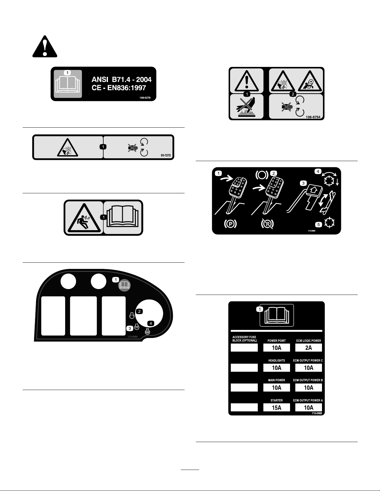
110-8924
1.Warning—readtheOperator’sManualandreceivetraining.
2.Thrownobjecthazard—keepbystandersasafedistance
fromthemachine.
3.Warning—donotparkthemachineonslopes;engagethe
parkingbrake,lowerthecuttingunits,stoptheengineand
removetheignitionkeybeforeleavingthemachine.
4.Tippinghazard—slowmachinebeforeturning,donotturn
athighspeeds;lowerthecuttingunitwhendrivingdown
slopes.
5.Warning—readtheOperator’sManual,donottowthe
machine.
110-8986
(Afxoverpartno.110–8924forCE*)
*Thissafetydecalincludesaslopewarningrequiredonthemachine
forcompliancetotheEuropeanLawnMowerSafetyStandardEN836:1997.The
conservativemaximumslopeanglesindicatedforoperationofthismachineare
prescribedbyandrequiredbythisstandard.
1.Warning—readtheOperator’sManualandreceivetraining.
2.Thrownobjecthazard—keepbystandersasafedistance
fromthemachine.
3.Warning—donotparkthemachineonslopes;engagethe
parkingbrake,lowerthecuttingunits,stoptheengineand
removetheignitionkeybeforeleavingthemachine.
4.Tippinghazard—donotoperateonslopesgreaterthan15°.
5.Warning—readtheOperator’sManual,donottowthe
machine.
110-8921
1.Tractionunitspeed
2.Slow
3.Fast
110-9642
1.Storedenergyhazard—readtheOperator’sManual.
2.Movethecotterpintotheholeclosesttotherodbracket
andthenremovetheliftarmandpivotyoke.
106-6755
1.Enginecoolantunder
pressure.
2.Explosionhazard—read
theOperator’sManual.
3.Warning—donottouch
thehotsurface.
4.Warning—readthe
Operator’sManual.
93-6689
1.Warning—donotcarrypassengers.
8
Page 9

1.Headlights
2.Reels—enabled
3.Reelsdisabled—liftonly
4.Reelsloweredandon
whenenabled—forward
andbacklap
110-0998
5.Reelsraisedandoff
6.Throttle—fast
7.Throttle—slow
8.ReadtheOperator’s
Manual.
BatterySymbols
Someorallofthesesymbolsareonyourbattery
1.Explosionhazard
2.Nore,opename,or
smoking.
3.Causticliquid/chemical
burnhazard
4.Weareyeprotection9.Flusheyesimmediately
5.ReadtheOperator’s
Manual.
6.Keepbystandersasafe
7.Weareyeprotection;
8.Batteryacidcancause
10.Containslead;donot
distancefromthebattery .
explosivegasescan
causeblindnessandother
injuries
blindnessorsevereburns.
withwaterandgetmedical
helpfast.
discard.
9
Page 10
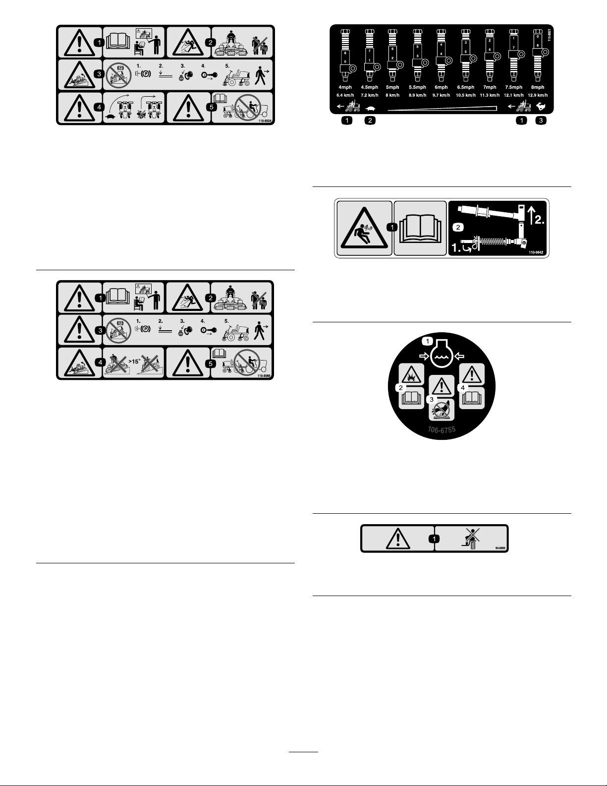
(UseforModels5510&5610with7inchreelcuttingunits)
1.Frontreelscircuitcontrols3.Mowandbacklap
2.Rearreelscircuitcontrols
4.ReadtheOperator’sManual.
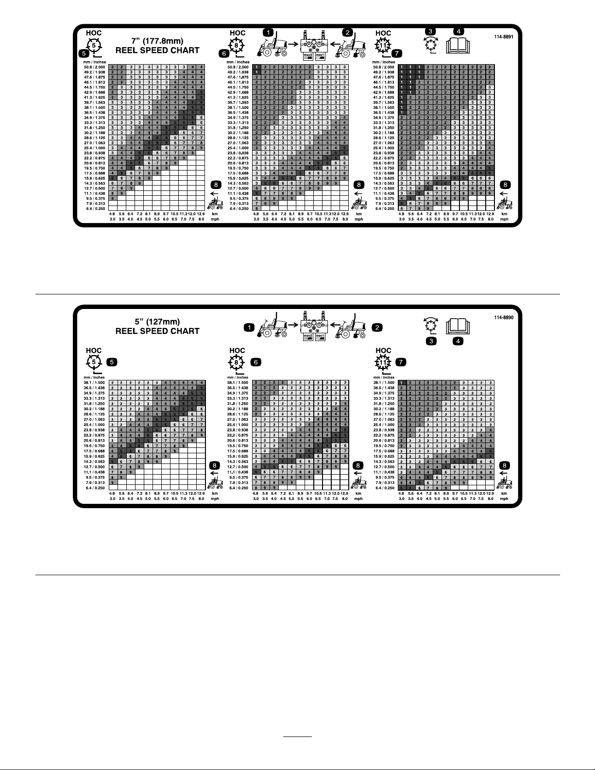
(UseforModels5210&5410with5inchreelcuttingunits)
1.Frontreelscircuitcontrols3.Mowandbacklap
2.Rearreelscircuitcontrols
4.ReadtheOperator’sManual.
114–8891
5.Height-of-cut
6.Tractionunitspeed
114–8890
5.Height-of-cut
6.Tractionunitspeed
10
Page 11
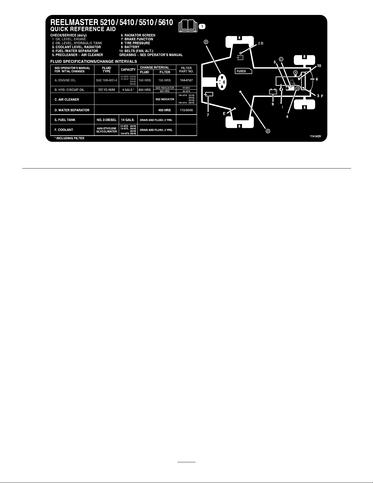
1.ReadtheOperator’sManual.
114-0429
11
Page 12

Setup
LooseParts
Usethechartbelowtoverifythatallpartshavebeenshipped.
ProcedureDescription
1
2
3
4
5
6
7
8
9
10
Nopartsrequired
Nopartsrequired
Nopartsrequired
Fronthoseguide-R.H.1
Fronthoseguide-L.H.1
Nopartsrequired
Rearweights(sizevarieswith
conguration).
Hoodlatchassembly1
Washer1
Cuttingunitkickstand
Gaugebar
Operator’sManual
EngineOperator’sManual
PartsCatalog
CEcerticate
OperatorTrainingMaterial
Varies
Qty.
Use
–
–
–
–
1
1
1
1
1
1
1
Adjustthetirepressure.
Adjustthestepheight.
Adjustthecontrolarmposition.
Installthecuttingunits
Adjusttheturfcompensationspring.
Installrearweights(orderfromyour
ToroDistributor).
InstalltheCEHoodLatch
InstalltheCuttingUnitKickstand.
Usethegaugebartoadjustthecutting
unit.
ReadtheOperator’sManualandwatch
thevideobeforeoperatingthemachine.
Note:Determinetheleftandrightsidesofthemachine
fromthenormaloperatingposition.
1
AdjustingtheTirePressure
NoPartsRequired
Procedure
Thetiresareover-inatedforshipping.Therefore,
releasesomeoftheairtoreducethepressure.Correct
airpressureinthefrontandreartiresis12to15psi(83
to103kPa).
Important:Maintainevenpressureinalltiresto
ensureuniformcontactwiththeturf.
2
AdjustingtheStepHeight
NoPartsRequired
Procedure
Theheightofthestepscanbeadjustedfortheoperators
comfort.
1.Removethe2boltsandnutssecuringthestep
bracketstothetractionunitframe(Figure2)
12
Page 13
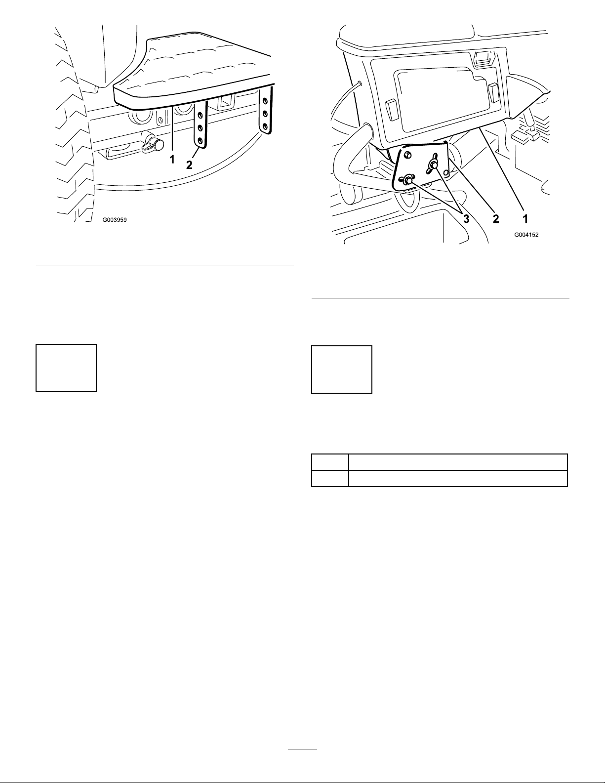
Figure2
1.Step2.Stepbrackets
2.Raiseorlowerthesteptothedesiredheightand
re-securethebracketstotheframewiththe2bolts
andnuts.
3.Repeattheprocedureontheotherstep.
Figure3
1.Controlarm3.Bolts(2)
2.Retainingbrackets
2.Rotatethecontrolarmtothedesiredpositionand
tightenthe2bolts.
3
AdjustingtheControlArm
Position
NoPartsRequired
Procedure
Thecontrolarmpositioncanbeadjustedforthe
operatorscomfort.
1.Loosenthe2boltssecuringthecontrolarmtothe
retainingbracket(Figure3).
4
InstallingtheCuttingUnits
Partsneededforthisprocedure:
1Fronthoseguide-R.H.
1Fronthoseguide-L.H.
Procedure
1.Removethereelmotorsfromtheshippingbrackets.
2.Removetheshippingbracketsanddiscard.
3.Removethecuttingunitsfromthecartons.Assemble
andadjustasdescribedinthecuttingunitOperator’s
Manual.
4.Makesurethecounterweight(Figure4)isinstalled
totheproperendofthecuttingunitasdescribedin
thecuttingunitOperator’sManual.
13
Page 14
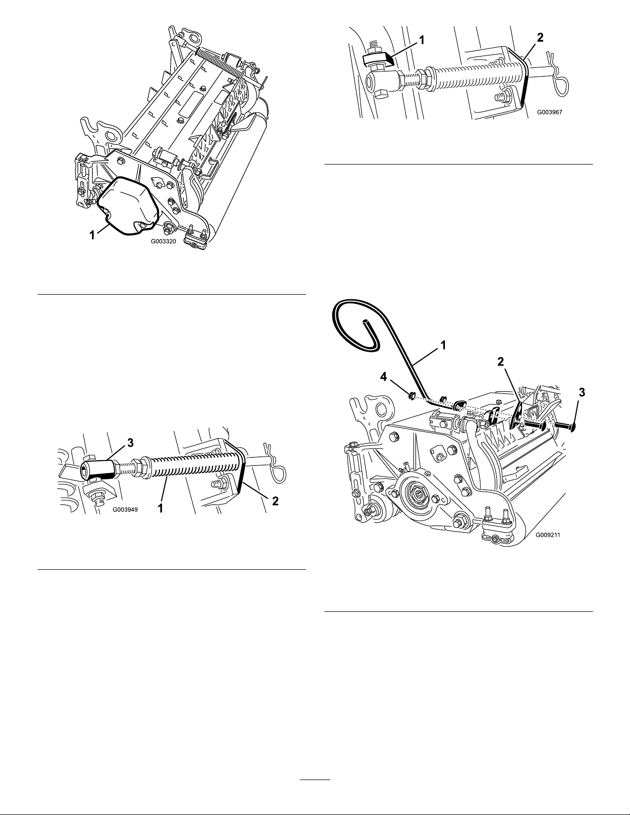
Figure6
1.Oppositecarrierframetab
2.Rodbracket
D.Mounttherodbrackettothecuttingunittabs
withthecarriageboltsandnuts(Figure6).Also,
onthe#4cuttingunit,mountthelefthandhose
guidetothefrontofthecuttingunittabswhen
reinstallingtherodbracket(Figure7).
Figure4
1.Counterweight
5.Allthecuttingunitsareshippedwiththeturf
compensationspringmountedtotherightsideof
thecuttingunit.Theturfcompensationspring
mustbemountedtothesamesideofthecutting
unitasthereeldrivemotor.Repositiontheturf
compensationasfollows:
A.Removethe2carriageboltsandnutssecuring
therodbrackettothecuttingunittabs(Figure5).
Figure5
1.Turfcompensationspring3.Springtube
2.Rodbracket
B.Removetheangenutsecuringthespringtube
capscrewtothecarrierframetab(Figure5)
Removetheassembly .
C.Mountthespringtubecapscrewtotheopposite
tabonthecarrierframeandsecurewiththe
angenut.Thecapscrewheadistobepositioned
totheoutersideofthetabasshowninFigure6.
Note:Onthe#5cuttingunit,usetherod
bracketmountingnutstoinstalltherighthand
hoseguidetothefrontofthecuttingunittabs.
Figure7
1.Hoseguide(Lefthand
shown)
2.Rodbracket4.Nuts
3.Carriagebolts
Note:Wheninstallingorremovingthecutting
units,makesurethehairpincotterisinstalled
inthespringrodholenexttotherodbracket.
Otherwise,thehairpincottermustbeinstalledin
theholeintheendoftherod.
6.Loweralltheliftarmscompletely.
7.Removethesnapperpinandthecapfromthelift
armpivotyoke(Figure8).
14
Page 15
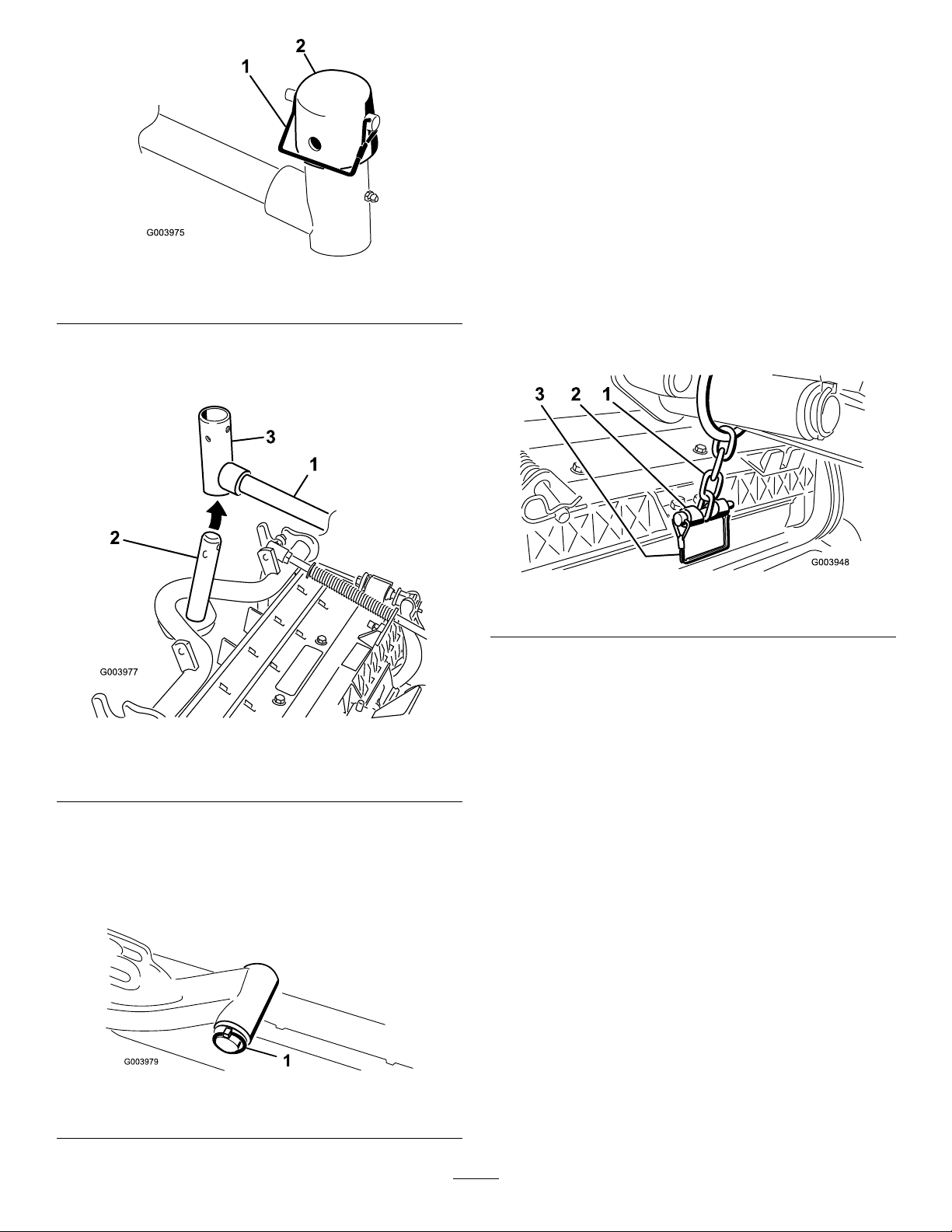
Figure8
1.Snapperpin2.Cap
8.Forthefrontcuttingunits,slideacuttingunitunder
theliftarmwhileinsertingthecarrierframeshaftup
intotheliftarmpivotyoke(Figure9).
B.Inserttheliftarmyokeontothecarrierframe
shaft(Figure9).
C.Inserttheliftarmshaftintotheliftarm
andsecureitwiththewasherandlynchpin
(Figure10).
10.Insertthecapoverthecarrierframeshaftandlift
armyoke.
11.Securethecapandthecarrierframeshafttothe
liftarmyokewiththesnapperpin.Usetheslotifa
steeringcuttingunitisdesiredorusetheholeifthe
cuttingunitistobelockedinposition(Figure8).
12.Securetheliftarmchaintothechainbracketwith
thesnapperpin(Figure11).Usethenumberofchain
linksdescribedinthecuttingunitOperator’ sManual.
Figure9
1.Liftarm3.Liftarmpivotyoke
2.Carrierframeshaft
9.Usethefollowingprocedureontherearcuttingunits
whentheheightofcutisabove3/4inch.
A.Removethelynchpinandwashersecuringthe
liftarmpivotshafttotheliftarmandslidethe
liftarmpivotshaftoutoftheliftarm(Figure10).
Figure11
1.Liftarmchain2.Chainbracket
13.Coatthesplineshaftofthereelmotorwithclean
grease.
14.OilthereelmotorO-ringandinstallitontothe
motorange.
15.Installthemotorbyrotatingitclockwisesothat
themotorangesclearthecapscrews(Figure12).
Rotatethemotorcounterclockwiseuntiltheanges
encirclethecapscrewsthentightenthecapscrews.
Important:Makesurethereelmotorhoses
arenottwisted,kinkedorintheriskofbeing
pinched.
Figure10
1.Liftarmpivotshaftlynchpinandwasher
15
Page 16
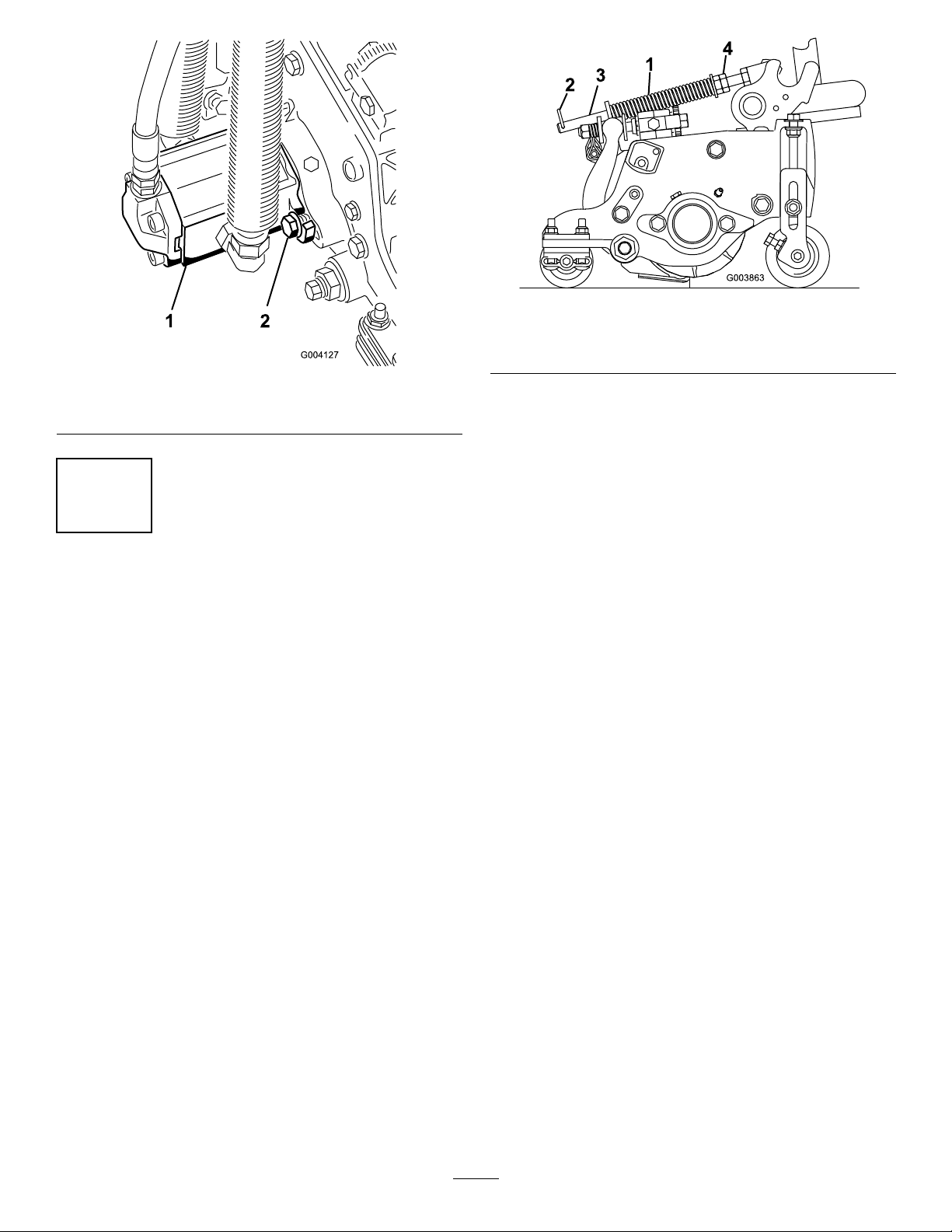
Figure12
1.Reeldrivemotor2.Mountingcapscrews
Figure13
1.Turfcompensationspring3.Springrod
2.Hairpincotter4.Hexnuts
2.Tightenthehexnutsonthefrontendofthespring
roduntilthecompressedlengthofthespringis5
inches(12.7cm)onReelmaster5210&5410,5inch
cuttingunitsor6.25inches(15.9cm)onReelmaster
5510&5610,7inchcuttingunits(Figure13).
5
AdjustingtheTurf
CompensationSpring
NoPartsRequired
Procedure
Theturfcompensationspring(Figure13)transfers
weightfromthefronttotherearroller.(Thishelps
toreduceawavepatternintheturf,alsoknownas
marcellingorbobbing.)
Important:Makespringadjustmentswiththe
cuttingunitmountedtothetractionunit,pointing
straightaheadandloweredtotheshopoor.
1.Makesurethehairpincotterisinstalledintherear
holeinthespringrod(Figure13).
Note:Whenoperatingonroughterraindecrease
thespringlengthby1/2inch.Groundfollowingwill
beslightlydecreased.
16
Page 17

6
InstallingRearWeights
Partsneededforthisprocedure:
Varies
Rearweights(sizevarieswithconguration).
Procedure
TheReelmaster5210/5410/5510and5610TractionUnitscomplywithCENstandardEN836:1997,ISOstandard
5395:1990,andANSIB71.4-2004Standardswhenequippedwithrearweightsand/or90lbofcalciumchloride
ballastisaddedtorearwheels.Usethefollowingchartstodeterminethecombinationsofweightsrequiredforyour
conguration.OrderpartsfromyourlocalAuthorizedToroDistributor.
WeightP/N110-8985-03
Tractor
RM5210
RM5410
RM5510
RM5610
2*or4
Wheel
Drive
2*
4
2*
4
2*
4
2*
4
Groomers,roller
brushes,and/or
baskets
No00
Yes
No00
Yes20
No00
Yes
No00
Yes20
No40
Yes
No00
Yes44
No00
Yes94
No00
Yes00
Numberof
weightsto
meetANSI(US)
standards
90lbcalcium
chloride**
90lbcalcium
chloride**
90lbcalcium
chloride**
Numberof
weightstomeet
CE(European)
standards
90lbcalcium
chloride**
Fasteners(2
eachrequired)
forweights
N/AN/A
7
9
3231-11Carriage
Bolt,104-8301Nut
N/AN/A
3231-6Carriage
Bolt,104-8301Nut
N/AN/A
3231-34Carriage
Bolt,104-8301Nut
N/AN/A
3231-6Carriage
Bolt,104-8301Nut
3231-7Carriage
Bolt,104-8301Nut
N/AN/A
N/AN/A
3231-7Carriage
Bolt,104-8301Nut
N/AN/A
3231-34Carriage
Bolt,104-8301Nut
N/AN/A
N/AN/A
WeightLocation
Underbumper
Underbumper
Underbumper
Underbumper
1ontopofbumper
and3under
bumper
1ontopofbumper
and3under
bumper
Underbumper
*Includes2WDunitswiththeROPSoption.
**Installtubesinsidethereartiresbeforeaddingcalciumchloride.
17
Page 18

Usethefollowingcharttodeterminetherearweightrequirementswhena4PostROPSConversionKitisadded.
WeightP/N110-8985-03
Tractor
RM5210
RM5410
RM5510
RM5610
2*or4
Wheel
Drive
2*
4
2*
4
2*
4
2*
4
Groomers,roller
brushes,and/or
baskets
No99
Yes
No
Yes
No99
Yes
No44
Yes
No
Yes
No44
Yes
No44
Yes
No00
Yes44
Numberof
weightsto
meetANSI(US)
standards
90lbcalcium
chloride**plus
5weights
90lbcalcium
chloride**
90lbcalcium
chloride**
90lbcalcium
chloride**plus
5weights
90lbcalcium
chloride**
90lbcalcium
chloride**
90lbcalcium
chloride**plus
9weights
90lbcalcium
chloride**
90lbcalcium
chloride**plus
2weights
Numberof
weightstomeet
CE(European)
standards
90lbcalcium
chloride**
90lbcalcium
chloride**
90lbcalcium
chloride**
90lbcalcium
chloride**
90lbcalcium
chloride**plus
5weights
90lbcalcium
chloride**
Fasteners(2
eachrequired)
forweights
3231-34Carriage
Bolt,104-8301Nut
3231-11Carriage
Bolt,104-8301Nut
N/AN/A
N/AN/A
3231-34Carriage
Bolt,104-8301Nut
9
9
9
3231-34Carriage
Bolt,104-8301Nut
3231-7Carriage
Bolt,104-8301Nut
N/AN/A
3231-34Carriage
Bolt,104-8301Nut
3231-34Carriage
Bolt,104-8301Nut
3231-7Carriage
Bolt,104-8301Nut
N/AN/A
3231-7Carriage
Bolt,104-8301Nut
3231-34Carriage
Bolt,104-8301Nut
N/AN/A
3231-7Carriage
Bolt,104-8301Nut
WeightLocation
2ontopofbumper
and7under
bumper
Underbumper
2ontopofbumper
and7under
bumper
2ontopofbumper
andtheremaining
underbumper
1ontopofbumper
and3under
bumper
2ontopofbumper
and7under
bumper
2ontopofbumper
andtheremaining
underbumper
1ontopofbumper
and3under
bumper
Underbumper
2ontopofbumper
andtheremaining
underbumper
1ontopofbumper
and3under
bumper
*Includes2WDunitswiththeROPSoption.
**Installtubesinsidethereartiresbeforeaddingcalciumchloride.
18
Page 19

Usethefollowingcharttodeterminetherearweightrequirementswhenthetractionunitisalsoequippedwitha
SunshadeCanopyona2PostROPS.
WeightP/N110-8985-03
Tractor
RM5210
RM5410
RM5510
RM5610
2*or4
Wheel
Drive
2*
4
2*
4
2*
4
2*
4
Groomers,roller
brushes,and/or
baskets
No20
Yes
No00
Yes42
No22
Yes
No00
Yes42
No62
Yes
No00
Yes66
No00
Yes
No00
Yes00
Numberof
weightsto
meetANSI(US)
standards
90lbcalcium
chloride**
90lbcalcium
chloride**
90lbcalcium
chloride**
90lbcalcium
chloride**
Numberof
weightstomeet
CE(European)
standards
90lbcalcium
chloride**
Fasteners(2
eachrequired)
forweights
3231-6Carriage
Bolt,104-8301Nut
9
9
6
3231-34Carriage
Bolt,104-8301Nut
N/AN/A
3231-7Carriage
Bolt,104-8301Nut
3231-6Carriage
Bolt,104-8301Nut
3231-34Carriage
Bolt,104-8301Nut
N/AN/A
3231-7Carriage
Bolt,104-8301Nut
3231-34Carriage
Bolt,104-8301Nut
N/AN/A
N/AN/A
3231-34Carriage
Bolt,104-8301Nut
N/AN/A
3231-34Carriage
Bolt,104-8301Nut
N/AN/A
N/AN/A
WeightLocation
Underbumper
Underbumper
1ontopofbumper
andtheremaining
underbumper
Underbumper
2ontopofbumper
and7under
bumper
Underbumper
Underbumper
3ontopofbumper
and3under
bumper
2ontopofbumper
and4under
bumper
*Includes2WDunitswiththeROPSoption.
**Installtubesinsidethereartiresbeforeaddingcalciumchloride.
Important:Alwaysinstalltubesinsidethereartiresbeforecalciumchlorideisinstalled.Ifapuncture
occursinatirewithcalciumchloride,removethemachinefromtheturfareaasquicklyaspossible.To
preventpossibledamagetotheturf,immediatelysoaktheaffectedareawithwater.
Ontwowheeldrivemodels,mounttheappropriateamountofweight(seeweightcharts)tothetoporbottomof
therearbumperasshowninFigure14.
19
Page 20

Figure14
1.Weight3.Nut
2.Carriagebolt
Onfourwheeldrivemodels,usethefollowingproceduretomounttheappropriateamountofweight(seeweight
charts)tothetoporbottomoftherearbumperasshowninFigure15.
Figure15
1.Tractionmanifold5.Weight(s)
2.Spacers6.Carriagebolt
3.Bolts7.Nut
4.Washers
•Removethe3bolts,washers,andspacerssecuringthetractionmanifoldtothebottomoftherearbumper
(Figure15a).
•Positiontheappropriateamountofweightonthetopand/orbottomoftherearbumper.
•Mounttheweight(s)andthetractionmanifoldtothebumperwiththe3bolts,washersandspacerspreviously
removed(Figure15b).
Note:Donotusethespacerswheninstallingmorethantwoweightsunderthebumper(Figure15c).
•Securetheouteredgesoftheweight(s)tothebumperwith2carriageboltsandnuts(Figure15c).
20
Page 21

7
InstallingtheCEHoodLatch
Partsneededforthisprocedure:
1Hoodlatchassembly
1Washer
4.Outsidethehood,insertthehookendofthelatch
throughtheholeinthehood.Makesuretherubber
sealingwasherremainstotheoutersideofthehood.
5.Insidethehood,insertthemetalwasherontothe
latchandsecurewiththenut.Makesurethelatch
engagestheframecatchwhenitislocked.Usethe
enclosedhoodlatchkeytooperatethehoodlatch.
8
Procedure
1.Unlatchandraisethehood.
2.Removetherubbergrommetfromtheholeinthe
leftsideofthehood(Figure16).
Figure16
1.Rubbergrommet
UsingtheCuttingUnit
Kickstand
Partsneededforthisprocedure:
1
Cuttingunitkickstand
Procedure
Wheneverthecuttingunithastobetippedtoexposethe
bedknife/reel,propuptherearofthecuttingunitwith
thekickstandtomakesurethenutsonthebackendof
thebedbaradjustingscrewsarenotrestingonthework
surface(Figure18).
3.Removethenutfromthehoodlatchassembly
(Figure17).
Figure17
1.Hoodlatch3.Rubberwasher
2.Nut4.Metalwasher
Figure18
1.Cuttingunitkickstand
Securethekickstandtothechainbracketwiththe
snapperpin(Figure19).
21
Page 22

Figure19
1.Chainbracket3.Cuttingunitkickstand
2.Snapperpin
9
UsingtheGaugeBar
Figure20
1.Gaugebar4.Holesusedforsetting
GroomerHOG
2.Heightadjustingscrew5.Holenotused
3.Nut
10
ReadingtheManualand
ViewingtheSafetyVideo
Partsneededforthisprocedure:
1
Gaugebar
Procedure
Usethegaugebartoadjustthecuttingunit.Referto
theCuttingUnitOperator’ sManualfortheadjustment
procedures(Figure20).
Partsneededforthisprocedure:
1
Operator’sManual
1
EngineOperator’sManual
1
PartsCatalog
1
CEcerticate
1
OperatorTrainingMaterial
Procedure
•ReadtheOperator’ sManual.
•ViewtheOperatorTrainingMaterial.
•Storealldocumentationinasafeplaceforfutureuse.
•Fillouttheregistrationcard.
•UsethediagnosticACEdisplayoverlaywhen
troubleshootingproblemswiththemachine(storeit
intheserviceshopuntilneeded).
22
Page 23

ProductOverview
1.Enginehood
2.Operator’sseat
3.Controlarm
4.Steeringwheel
Controls
SeatAdjustingKnobs
Figure21
5.Seat
6.Frontcuttingunits
7.Rearcuttingunits
speeddependsonhowfaryoupressthepedal.Forno
load,maximumgroundspeed,fullypressthepedalwhile
thethrottleisintheFastposition.
Tostop,reducefootpressureonthetractionpedaland
allowittoreturntothecenterposition.
Figure23
1.Tractionpedal4.Brakepedal
2.Mowspeedlimiter5.Parkingbrake
3.Spacers
6.Tiltsteeringpedal
Theseatadjustinglever(Figure22)allowsyoutoadjust
theseatforeandaft.Theweightadjustingknobadjusts
theseatfortheoperator’ sweight.Theweightgauge
indicateswhentheseatisadjustedtotheweightofthe
operator.Theheightadjustingknobadjuststheseatfor
theoperator’ sheight.
Figure22
1.Weightgauge3.Heightadjustingknob
2.Weightadjustingknob
4.Adjustinglever(foreand
aft)
TractionPedal
Thetractionpedal(Figure23)controlstheforwardand
reverseoperation.Pressthetopofthepedaltomove
forwardandthebottomtomoverearward.Ground
MowSpeedLimiter
Whenthemowspeedlimiter(Figure23)isippedupit
willcontrolthemowspeedandallowthecuttingunits
tobeengaged.Eachspaceradjuststhemowingspeed
by½mileperhour.Themorespacersyouhave,onthe
topoftheboltthesloweryouwillgo.Fortransport,ip
backthemowspeedlimiterandyouwillhavemaximum
transportspeed.
BrakePedal
Pressthebrakepedal(Figure23)tostopthemachine.
ParkingBrake
Toengagetheparkingbrake,(Figure23)pushdownon
thebrakepedalandpressthetopforwardtolatch.T o
releasetheparkingbrake,pressthebrakepedaluntilthe
parkingbrakelatchretracts.
TiltSteeringPedal
Totiltthesteeringwheeltowardsyou,pressthefoot
pedal(Figure23)down,andpullthesteeringtower
towardyoutothemostcomfortablepositionandthen
releasethepedal.
23
Page 24

ThrottleControl
LowerMow/RaiseControlLever
Movethethrottlecontrol(Figure24)forwardtoincrease
theenginespeedandrearwardtodecreasespeed.
Figure24
1.Throttlecontrol6.Enginecoolant
2.Enable/disableswitch
3.Glowplugindicatorlight8.Chargeindicator
4.Enginecoolant
temperaturewarning
light
5.Diagnosticlight
temperaturegauge
7.Engineoilpressure
warninglight
9.Keyswitch
10.Lowermow/raisecontrol
lever
KeySwitch
Thekeyswitch(Figure24)hasthreepositions:Off,
On/Preheat,andStart.
EngineCoolantTemperatureWarning
Light
Thislever(Figure24)raisesandlowersthecuttingunits
andalsostartsandstopsthereelswhenthereelsare
enabledinthemowmode.
GlowPlugIndicatorLight
Thislight(Figure24)illuminateswhentheglowplugs
arepreheating.
EngineOilPressureWarningLight
Thislight(Figure24)indicatesdangerouslylowengine
oilpressure.
ChargeIndicator
Thechargeindicator(Figure24)illuminateswhenthe
systemchargingcircuitmalfunctions.
Enable/DisableSwitch
Usetheenable/disableswitch(Figure24)inconjunction
withthelowermow/raisecontrollevertooperate
thereels.Thereelscannotbeloweredwhenthe
mow/transportleverisinthetransportposition.
BacklapLevers
Usethebacklapleversinconjunctionwiththelower
mow/raisecontrolleverforbacklappingthereels
(Figure25).
ReelSpeedControls
Thereelspeedcontrolscontrolthespeedofthefront
andrearcuttingunits(Figure25).Thereelspeed
increasesastheknobsareturnedcounterclockwise.
Thislight(Figure24)illuminatesandthereelsshutdown
whentheenginecoolantreachesahightemperature.
Iftheenginetemperaturecontinuestorise,theengine
willshutdown.
EngineCoolantTemperatureGauge
Duringnormaloperatingconditionsthegauge
(Figure24)shouldbeinthegreenrange.Checkthe
coolingsystemifthegaugegoestotheyelloworred
range.
DiagnosticLight
Itwillilluminateshouldasystemfaultberecognized.
Figure25
1.Backlaplevers
2.Reelspeedcontrols
24
Page 25

HourMeter
FuelGauge
Thehourmeter(Figure26)showsthetotalhoursthat
themachinehasbeenoperated.
Figure26
1.Hourmeter
HydraulicFilterRestrictionIndicator
Thefuelgauge(Figure28)showstheamountoffuel
inthetank.
Figure28
1.Fueltankcap
2.Fuelgauge
Withtheenginerunningatnormaloperating
temperature,viewtheindicator(Figure27),itshouldbe
intheGreenzone.WhentheindicatorisintheRed
zone,changethehydrauliclters.
Figure27
1.Hydrauliclterrestrictionindicator
HeadlightSwitch
Pivottheswitchdownwardtoturnontheheadlights
(Figure29).
25
Figure29
1.Headlightswitch
Page 26

PowerPoint
Thepowerpointisa12voltpowersupplyforelectronic
devices(Figure30).
Specications
Note:Specicationsanddesignaresubjecttochange
withoutnotice.
Figure30
1.Powerpoint
SpecicationReelMaster®5210ReelMaster®5410ReelMaster®5510ReelMaster®5610
TransportWidth
Widthofcut100inches(254cm)100inches(254cm)100inches(254cm)100inches(254cm)
Length
Height
Weight
EngineKubota28hpKubota35.5hpKubota35.5hp
Fueltankcapacity
Transportspeed
Mowingspeed
90inches(228cm)90inches(228cm)92inches(233cm)92inches(233cm)
11 1inches(282cm)11 1inches(282cm)11 1inches(282cm)11 1inches(282cm)
62inches(157cm)63inches(160cm)63inches(160cm)63inches(160cm)
2,396lb(1,087kg)2,505lb(1,136kg)2,693lb(1,222kg)2,813lb(1,276kg)
Kubota44.2hp(Turbo)
13.5USgallons(51l)13.5USgallons(51l)13.5USgallons(51l)13.5USgallons(51l)
0–10mph(0–16kph)0–10mph(0–16kph)0–10mph(0–16kph)0–10mph(0–16kph)
0–8mph(0–13kph)0–8mph(0–13kph)0–8mph(0–13kph)0–8mph(0–13kph)
Attachments/Accessories
AselectionofToroapprovedattachmentsand
accessoriesareavailableforusewiththemachineto
enhanceandexpanditscapabilities.Contactyour
AuthorizedServiceDealerorDistributororgoto
www.Toro.comforalistofallapprovedattachments
andaccessories.
26
Page 27

Operation
Note:Determinetheleftandrightsidesofthe
machinefromthenormaloperatingposition.
Ifyouleavethekeyintheignitionswitch,
someonecouldaccidentlystarttheengineand
seriouslyinjureyouorotherbystanders.
Lowerthecuttingunitstotheground,setthe
parkingbrakeandremovethekeyfromthe
ignitionswitchbeforeservicingormaking
adjustmentstothemachine.
CheckingtheEngineOilLevel
Theengineisshippedwithoilinthecrankcase;
however,theoillevelmustbecheckedbeforeandafter
theengineisrststarted.
Crankcasecapacityformodel5210isapproximately
3.5qt.(3.3l)withthelter.Crankcasecapacityfor
models5410,5510and5610isapproximately5.5qt.
(5.2l)withthelter.
Figure31
1.Dipstick
4.Removedipstickandcheckoillevelondipstick.
TheoillevelshouldbeuptotheFullmark.
5.IftheoillevelisbelowtheFullmark,removethe
llcap(Figure32)andaddoiluntillevelreaches
theFullmarkondipstick.
Usehigh-qualityengineoilthatmeetsthefollowing
specications:
•APIClassicationLevelRequired:CH-4,CI-4or
higher
•Preferredoil:SAE15W-40(above0degreesF)
•Alternateoil:SAE10W-30or5W -30(all
temperatures)
ToroPremiumEngineoilisavailablefromyour
distributorineither15W-40or10W -30viscosity .
1.Parkthemachineonalevelsurface,stoptheengine,
settheparkingbrakeandremovethekeyfromthe
ignitionswitch.
2.Openthehood.
3.Removethedipstick,wipeitclean,andinstallit
(Figure31).
Figure32
1.Oilllcap
Donotoverll.
Important:Besuretokeeptheengineoillevel
betweentheupperandlowerlimitsontheoil
27
Page 28

gauge.Enginefailuremayoccurasaresultof
overllingorunderllingtheengineoil.
2.Ifthecoolantlevelislow ,removetheexpansion
tankcapandreplenishthesystem.Donotoverll.
6.Installtheoilllcapandclosethehood.
CheckingtheCoolingSystem
Cleandebrisoffofthescreen,oilcooler,andfront
oftheradiatordailyandmoreoftenifconditionsare
extremelydustyanddirty.Refertothesectionon
RemovingDebrisfromtheCoolingSystemin,page.
Thecoolingsystemislledwitha50/50solution
ofwaterandpermanentethyleneglycolantifreeze.
Checkthelevelofcoolantintheexpansiontankatthe
beginningofeachdaybeforestartingtheengine.The
capacityofthecoolingsystemforthemodel5210is5.5
quarts(5.2l).Thecapacityformodel5410is7.0quarts
(6.6l)andmodels55105610is10.0quarts(9.5l).
Iftheenginehasbeenrunning,thepressurized,
hotcoolantcanescapeandcauseburns.
•Donotopentheradiatorcapwhenthe
engineisrunning.
•Usearagwhenopeningtheradiatorcap,
andopenthecapslowlytoallowsteamto
escape.
1.Checkthelevelofcoolantintheexpansiontank
(Figure33).
3.Installtheexpansiontankcap.
AddingFuel
Useonlyclean,freshdieselfuelorbiodieselfuelswith
low(<500ppm)orultralow(<15ppm)sulfurcontent.
Theminimumcetaneratingshouldbe40.Purchase
fuelinquantitiesthatcanbeusedwithin180daysto
ensurefuelfreshness.
Fueltankcapacity:13.5gallons(51l)
Usesummergradedieselfuel(No.2-D)attemperatures
above20°F(-7°C)andwintergrade(No.1-Dor
No.1-D/2-Dblend)belowthattemperature.Useof
wintergradefuelatlowertemperaturesprovideslower
ashpointandcoldowcharacteristicswhichwillease
startingandreducefuellterplugging.
Useofsummergradefuelabove20°F(-7°C)will
contributetowardlongerfuelpumplifeandincreased
powercomparedtowintergradefuel.
Important:Donotusekeroseneorgasoline
insteadofdieselfuel.Failuretoobservethis
cautionwilldamagetheengine.
Fuelisharmfulorfatalifswallowed.Long-term
exposuretovaporscancauseseriousinjuryand
illness.
Thecoolantlevelshouldbebetweenthemarkson
thesideofthetank.
Figure33
1.Expansiontank
•Avoidprolongedbreathingofvapors.
•Keepfaceawayfromnozzleandgastankor
conditioneropening.
•Keepfuelawayfromeyesandskin.
BiodieselReady
Thismachinecanalsouseabiodieselblendedfuel
ofuptoB20(20%biodiesel,80%petrodiesel).The
petrodieselportionshouldbeloworultralowsulfur.
Observethefollowingprecautions:
•Thebiodieselportionofthefuelmustmeet
specicationASTMD6751orEN14214.
•TheblendedfuelcompositionshouldmeetASTM
D975orEN590.
•Paintedsurfacesmaybedamagedbybiodiesel
blends.
•UseB5(biodieselcontentof5%)orlesserblends
incoldweather.
28
Page 29

•Monitorseals,hoses,gasketsincontactwithfuelas
theymaybedegradedovertime.
•Fuellterpluggingmaybeexpectedforatimeafter
convertingtobiodieselblended.
•Contactyourdistributorifyouwishformore
informationonbiodiesel.
Incertainconditions,fuelisextremely
ammableandhighlyexplosive.Areor
explosionfromfuelcanburnyouandothers
andcandamageproperty.
•Fillthefueltankoutdoors,inanopenarea,
whentheengineiscold.Wipeupanyfuel
thatspills.
•Neverllthefueltankinsideanenclosed
trailer.
•Neversmokewhenhandlingfuel,andstay
awayfromanopenameorwherefuel
fumesmaybeignitedbyaspark.
•Storefuelinanapprovedcontainerandkeep
itoutofthereachofchildren.Neverbuy
morethana30-daysupplyoffuel.
•Donotoperatewithoutentireexhaust
systeminplaceandinproperworking
condition.
Incertainconditionsduringfueling,static
electricitycanbereleasedcausingaspark
whichcanignitethefuelvapors.Areor
explosionfromfuelcanburnyouandothers
andcandamageproperty.
•Alwaysplacefuelcontainersontheground
awayfromyourvehiclebeforelling.
•Donotllfuelcontainersinsideavehicle
oronatruckortrailerbedbecauseinterior
carpetsorplastictruckbedlinersmay
insulatethecontainerandslowthelossof
anystaticcharge.
•Whenpractical,removeequipmentfromthe
truckortrailerandrefueltheequipment
withitswheelsontheground.
•Ifthisisnotpossible,thenrefuelsuch
equipmentonatruckortrailerfroma
portablecontainer,ratherthanfromafuel
dispensernozzle.
•Ifafueldispensernozzlemustbeused,keep
thenozzleincontactwiththerimofthefuel
tankorcontaineropeningatalltimesuntil
fuelingiscomplete.
1.Parkthemachineonalevelsurface.
2.Usingacleanrag,cleanareaaroundfueltankcap.
3.Removecapfromthefueltank(Figure34).
Figure34
1.Fueltankcap2.Fuelgauge
29
Page 30

4.Fillthetankuntilthelevelistothebottomofthe
llerneckwithdieselfuel.
5.Installfueltankcaptightlyafterllingtank.
Note:Ifpossible,llthefueltankaftereachuse.
Thiswillminimizepossiblebuildupofcondensation
insidethefueltank.
bymineral-basedhydraulicuidswillchangethe
biodegradabilityandtoxicityofthisoil.Whenchanging
fromstandarduidtothebiodegradabletype,be
certaintofollowtheapprovedushingprocedure.
ContactyourlocalToroDistributorfordetails.
1.Positionmachineonalevelsurface,lowerthe
cuttingunitsandstoptheengine.
CheckingtheHydraulicFluid
Themachinesreservoirislledatthefactorywith
approximately8U .S.gallons(30l)ofhighquality
hydraulicuid.Checkthelevelofthehydraulicuid
beforetheengineisrststartedanddailythereafter.
Therecommendedreplacementuidisasfollows:
ToroPremiumAllSeasonHydraulicFluid(Availablein5
gallonpailsor55gallondrums.SeepartscatalogorT oro
distributorforpartnumbers.)
Alternateuids:IftheT orouidisnotavailable,other
uidsmaybeusedprovidedtheymeetallthefollowing
materialpropertiesandindustryspecications.Wedo
notrecommendtheuseofsyntheticuid.Consult
withyourlubricantdistributortoidentifyasatisfactory
productNote:T orowillnotassumeresponsibilityfor
damagecausedbyimpropersubstitutions,souseonly
productsfromreputablemanufacturerswhowillstand
behindtheirrecommendation.
HighViscosityIndex/LowPourPointAnti-wearHydraulic
Fluid,ISOVG46
MaterialProperties:
Viscosity,ASTMD445cSt@40°C44to48
ViscosityIndexASTM
D2270
PourPoint,ASTMD97-34°Fto-49°F
IndustrySpecications:
VickersI-286-S(QualityLevel),VickersM-2950-S
(QualityLevel),DenisonHF-0
cSt@100°C7.9to8.5
140to160
2.Ontherightsideofthemachine,raisethehydraulic
tankcover(Figure35).
Note:Manyhydraulicuidsarealmostcolorless,
makingitdifculttospotleaks.Areddyeadditive
forthehydraulicsystemoilisavailablein2/3oz.(20
ml)bottles.Onebottleissufcientfor4-6gal(15-22
1)ofhydraulicoil.Orderpartno.44-2500fromyour
authorizedTorodistributor.
BiodegradableHydraulicFluid-Mobil224H
ToroBiodegradableHydraulicFluid(Availablein5
gallonpailsor55gallondrums.SeepartscatalogorToro
distributorforpartnumbers.)
Alternateuid:MobilEAL224H
Note:Thisisvegetable-oilbasedbiodegradable
oiltestedandapprovedbyT oroforthismodel.
Thisuidisnotasresistanttohightemperaturesas
standarduid,sobesuretofollowtherecommended
uidchangeintervalswiththisuid.Contamination
Figure35
1.Hydraulictankcover
3.Cleanareaaroundllerneckandcapofhydraulic
tank(Figure36).Removecapfromllerneck.
30
Page 31

Figure36
1.Hydraulictankcap
4.Removedipstickfromllerneckandwipeitwith
acleanrag.Insertdipstickintollerneck;then
removeitandchecklevelofuid.Fluidlevelshould
be1/4inchofmarkondipstick.Donotoverll.
5.Iflevelislow,addappropriateuidtoraiselevel
tofullmark.
6.Installdipstickandcapontollerneck.
CheckingtheReeltoBedknife
•Initialstartupofanewmachine.
•Enginehasceasedrunningduetolackoffuel.
•Maintenancehasbeenperformeduponfuelsystem
components;i.e.,lterreplaced,separatorserviced,
etc.
Undercertainconditions,dieselfuelandfuel
vaporsarehighlyammableandexplosive.A
reorexplosionfromfuelcanburnyouand
othersandcancausepropertydamage.
•Useafunnelandllthefueltankoutdoors,
inanopenarea,whentheengineisoffand
iscold.Wipeupanyfuelthatspills.
•Donotllthefueltankcompletelyfull.Add
fueltothefueltankuntilthelevelis1/4to
1/2in.(6to13mm)belowthebottomof
thellerneck.Thisemptyspaceinthetank
allowsthefueltoexpand.
•Neversmokewhenhandlingfuel,andstay
awayfromanopenameorwherefuel
fumesmaybeignitedbyaspark.
•Storefuelinaclean,safety-approved
containerandkeepthecapinplace.
Contact
Eachdaybeforeoperating,checkreeltobedknife
contact,regardlessifthequalityofcuthadpreviously
beenacceptable.Theremustbelightcontactacross
thefulllengthofthereelandthebedknife(referto
AdjustingtheReeltoBedknifeinthecuttingunit
Operator’sManual).
ChecktheTorqueoftheWheel
Nuts
Torquethewheelnutsto70to90ft-lb(94to122
N⋅m).after1-4hoursofoperationandagainafter10
hoursofoperation.Torqueevery250hoursthereafter.
Failuretomaintainpropertorqueofthewheel
nutscouldresultinpersonalinjury.
1.Parkthemachineonalevelsurfaceandensurethat
thefueltankisatleasthalffull.
2.Openthehood.
3.Opentheairbleedscrewonthefuelinjectionpump
(Figure37)witha12mmwrench.
Figure37
1.Bleedscrew
BleedingtheFuelSystem
Youmustbleedthefuelsystembeforestartingthe
engineifanyofthefollowingsituationshaveoccurred:
4.TurnthekeyintheignitionswitchtotheOn
position.Theelectricfuelpumpwillbegin
operation,therebyforcingairoutaroundtheair
31
Page 32

bleedscrew .LeavethekeyintheOnpositionuntil
asolidstreamoffuelowsoutaroundthescrew .
5.TightenthescrewandturnthekeytotheOff
position.
Note:Normally,theengineshouldstartafterthe
abovebleedingproceduresarefollowed.However,
ifenginedoesnotstart,airmaybetrappedbetween
injectionpumpandinjectors;refertoBleedingAir
fromtheInjectorsin,page.
SettingtheReelSpeed
Toachieveaconsistent,highquality-of-cutanda
uniformaftercutappearance,itisimportantthatyou
setthereelspeedcontrols(locatedundertheseat)
correctly.Adjustthereelspeedcontrolsasfollows:
1.Selecttheheight-of-cutatwhichthecuttingunits
areset.
2.Choosethedesiredgroundspeedbestsuitedfor
conditions.
StartingandStoppingthe
Engine
Important:Youmustbleedthefuelsystembefore
startingtheengineifyouarestartingtheengine
forthersttime,theenginehasstoppeddueto
lackoffuel,oryouhaveperformedmaintenanceon
thefuelsystem;refertoBleedingtheFuelSystem.
StartingtheEngine
1.Sitontheseat,keepyourfootoffofthetraction
pedalsothatitisinNeutral,engagetheparking
brake,setthethrottletotheFastposition,and
ensurethattheEnable/Disableswitchisinthe
Disableposition.
2.TurntheignitionswitchtotheOn/Preheatposition.
Anautomatictimerwillcontroltheglowplug
preheatfor6seconds.
3.Afterpreheatingtheglowplugs,turnkeytothe
Startposition.
3.Usingtheappropriategraphondecal110–0996
(Figure39)forReelmaster5510&5610,7inch
reelcuttingunitsordecal110–8923(Figure40)for
Reelmaster5210&5410,5inchreelcuttingunits
determinetheproperreelspeedsetting.
Tosetthereelspeed,rotateknobs(Figure38)until
theindicatorarrowsareinlinewiththenumber
designatingthedesiredsetting.
Figure38
1.Reelspeedcontrolknobs
Cranktheenginefornolongerthan15seconds.
Releasethekeywhentheenginestarts.Ifadditional
preheatingisrequired,turnkeytotheOffposition
andthentotheOn/Preheatposition.Repeatthis
processasrequired.
4.Runtheengineatlowidlespeeduntilitwarmsup.
StoppingtheEngine
1.MoveallcontrolstoNeutral,settheparkingbrake,
movethethrottletothelowidlepositionandallow
theenginetoreachlowidlespeed.
Important:Allowtheenginetoidlefor5
minutesbeforeshuttingitoffafterafullload
operation.Failuretodosomayleadtotrouble
onaturbo-chargedengine.
2.TurnthekeytotheOffpositionandremoveit
fromtheswitch.
Note:Thereelspeedcanbeincreasedordecreased
tocompensateforturfconditions.
32
Page 33

1.Frontreelscircuitcontrols3.Reel—mowandbacklap
2.Rearreelscircuitcontrols
1.Frontreelscircuitcontrols3.Reel—mowandbacklap
2.Rearreelscircuitcontrols
4.ReadtheOperator’sManual.
4.ReadtheOperator’sManual.
Figure39
5.Reel—heightofcut
6.Machinespeed
Figure40
5.Reel—heightofcut
6.Machinespeed
AdjustingtheLiftArm
Counterbalance
Youcanadjustthecounterbalanceontherear
cuttingunitliftarmstocompensatefordifferentturf
conditionsandtomaintainauniformheight-of-cutin
theroughconditionsorinareasofthatchbuildup.
Youcanadjusteachcounterbalancespringtooneof
foursettings.Eachincrementincreasesordecreases
counterbalanceonthecuttingunitby5lb(2.3kg).The
springscanbepositionedonthebacksideofthespring
actuatortoremoveallcounterbalance(forthposition).
1.Positionthemachineonalevelsurface,lowerthe
cuttingunits,stoptheengine,engagetheparking
brakes,andremovethekeyfromignitionswitch.
2.Insertatubeorsimilarobjectontothelong
springendtorelievethespringtensionduringthe
adjustment(Figure41).
33
Page 34

Thespringsareundertension.
Usecautionwhenadjustingthem.
3.Whilerelievingthespringtension,removethebolt
andlocknutsecuringthespringactuatortothe
bracket(Figure41).
Figure41
1.Spring
2.Springactuator
4.Movethespringactuatortothedesiredhole
locationandsecurewithlocknut.
5.Repeattheprocedureontheremainingspring.
3.Holelocations
Figure42
1.Switch2.Liftarmsensingdevice
PushingorTowingthe
Machine
Inanemergency,themachinecanbemovedby
actuatingthebypassvalveinthevariabledisplacement
hydraulicpumpandpushingortowingthemachine.
Important:Donotpushortowthemachine
fasterthan2-3mph(3-4.8km/h)becauseinternal
transmissiondamagemayoccur.Thebypassvalve
mustbeopenwheneverthemachineispushedor
towed.
1.Thebypassvalveislocatedontheleftsideofthe
hydrostat(Figure43).Rotatethebolt1–1/2turns
toopenandallowoiltobypassinternally.Because
uidisbypassed,themachinecanbemovedslowly
withoutdamagingthetransmission.
AdjustingtheLiftArmTurn
AroundPosition
1.Positionthemachineonalevelsurface,lowerthe
cuttingunits,stoptheengine,engagetheparking
brakes,andremovethekeyfromignitionswitch.
2.Theliftarmswitchislocatedunderneaththe
hydraulictankbehindthefrontrightliftarm
(Figure42).
3.Loosentheswitchmountingscrews(Figure42)and
movetheswitchdowntoincreasetheliftarmturn
aroundheightormovetheswitchuptodecreasethe
liftarmturnaroundheight.Tightenthemounting
screws.
Figure43
1.Bypassvalve
2.Closethebypassvalvebeforestartingtheengine.
However,donotexceed5-8ft.-lb.(7-11N·m)
torquetoclosethevalve.
34
Page 35

Important:Runningtheenginewiththe
bypassvalveopenwillcausethetransmission
tooverheat.
JackingPoints
Note:Usejackstandstosupportthemachinewhen
required.
•Front—rectangularpad,undertheaxletube,inside
eachfronttire(Figure44).
Figure45
1.Fronttiedown
•Rear—eachsideofthemachineontherearframe
(Figure46).
Figure44
1.Frontjackingpoint
•Rear—rectangularaxletubeontherearaxle.
TieDowns
•Front—theholeintherectangularpad,underthe
axletube,insideeachfronttire(Figure45).
Figure46
1.Reartiedown
UnderstandingtheDiagnostic
Light
Themachineisequippedwithadiagnosticlightwhich
indicatesiftheelectroniccontrollersensesanelectronic
malfunction.Thediagnosticlightislocatedonthe
controlarm(Figure47).Whentheelectroniccontroller
isfunctioningcorrectlyandthekeyswitchismovedto
theOnposition,thecontrollerdiagnosticlightwillturn
ONfor3secondsandturnOFFtoindicatethelight
isworkingproperly .Ifthemachinekillsthelightwill
35
Page 36

turnonsteadyuntilthekeypositionischanged.The
lightwillblinkifthecontrollerdetectsamalfunctionin
theelectricalsystem.Thelightwillstopblinkingand
automaticallyresetwhenthekeyswitchisturnedtothe
Offpositiononcethefaulthasbeenresolved.
Figure47
1.Diagnosticlight
Whenthecontrollerdiagnosticlightblinks,oneofthe
followingproblemshasbeendetectedbythecontroller:
DiagnosticAceDisplay
Themachineisequippedwithanelectroniccontroller
whichcontrolsmostmachinefunctions.Thecontroller
determineswhatfunctionisrequiredforvariousinput
switches(i.e.seatswitch,keyswitch,etc.)andturns
ontheoutputstoactuatesolenoidsorrelaysforthe
requestedmachinefunction.
Fortheelectroniccontrollertocontrolthemachineas
desired,eachoftheinputswitches,outputsolenoids,
andrelaysmustbeconnectedandfunctioningproperly.
UsetheDiagnosticACEdisplaytohelpverifyand
correctelectricalfunctionsofthemachine.
CheckingtheInterlock
Switches
Thepurposeoftheinterlockswitchesistopreventthe
enginefromcrankingorstartingunlessthetraction
pedalisintheNeutralposition,theEnable/Disable
switchisintheDisableposition,andtheLower
Mow/RaisecontrolisintheNeutralposition.In
addition,theengineshouldstopwhenthetraction
pedalispressedwithoperatoroffoftheseatorifthe
parkingbrakeisleftengaged.
•Oneoftheoutputshasbeenshorted.
•Oneoftheoutputsisopencircuited.
Usingthediagnosticdisplay ,determinewhichoutput
ismalfunctioning;refertoCheckingtheInterlock
Switches.
Ifthediagnosticlightisnotilluminatedwhenthekey
switchisintheOnposition,thisindicatesthatthe
electroniccontrollerisnotoperating.Possiblecauses
areasfollows:
•Loop-backisnotconnected.
•Thelightisburnedout.
•Fusesareblown.
•Itisnotfunctioningcorrectly.
Checktheelectricalconnections,inputfuses,and
diagnosticlightbulbtodeterminethemalfunction.
Ensurethattheloop-backconnectorissecuredtothe
wireharnessconnector.
Ifsafetyinterlockswitchesaredisconnected
ordamagedthemachinecouldoperate
unexpectedlycausingpersonalinjury.
•Donottamperwiththeinterlockswitches.
•Checktheoperationoftheinterlock
switchesdailyandreplaceanydamaged
switchesbeforeoperatingthemachine.
VerifyingtheInterlockSwitchFunction
1.Parkthemachineonalevelsurface,lowerthe
cuttingunits,stoptheengine,andengagethe
parkingbrake.
2.Removetheaccesspanelfromthesideofthe
controlarm.
3.Locatethewireharnessandconnectorsnearthe
controller(Figure48).
36
Page 37

8.Individually,changeeachoftheswitchesfrom
opentoclosed(i.e.,sitonseat,engagetraction
pedal,etc.),andnotethattheappropriateLED
onDiagnosticACEwillblinkonandoffwhen
correspondingswitchisclosed.Repeatthisforall
switchesthatyoucanchangebyhand.
9.IfaswitchisclosedandtheappropriateLEDdoes
notturnon,checkallwiringandconnectionsto
theswitchand/orchecktheswitcheswithanohm
meter.Replaceanydefectiveswitchesandrepair
anydefectivewiring.
Figure48
1.Wireharnessandconnectors
4.Carefullyunplugloopbackconnectorfromharness
connector.
5.ConnecttheDiagnosticACEdisplayconnectorto
theharnessconnector(Figure49).
Note:Makesurecorrectoverlaydecalispositioned
onDiagnosticACEdisplay.
Note:TheDiagnosticACEalsohastheabilityto
detectwhichoutputsolenoidsorrelaysareturned
on.Thisisaquickwaytodetermineifamachine
malfunctioniselectricalorhydraulic.
VerifyingOutputFunction
1.Parkthemachineonalevelsurface,lowerthe
cuttingunits,stoptheengine,andengagethe
parkingbrake.
2.Removetheaccesspanelfromthesideofthe
controlarm.
3.Locatewireharnessandconnectorsnearcontroller.
4.Carefullyunplugloopbackconnectorfromharness
connector.
5.ConnecttheDiagnosticACEconnectortothe
harnessconnector.
Note:Makesurecorrectoverlaydecalispositioned
onDiagnosticACE.
6.TurnthekeyswitchtotheONposition,butdonot
startmachine.
Figure49
1.DiagnosticACE
6.TurnthekeyswitchtotheOnposition,butdonot
startthemachine.
Note:Theredtextontheoverlaydecalrefersto
inputswitchesandthegreentextreferstooutputs.
7.The“inputsdisplayed”LED ,onthelower
rightcolumnoftheDiagnosticACE,shouldbe
illuminated.Ifthe“outputsdisplayed”LEDis
illuminated,pressthetogglebutton,onDiagnostic
ACE,tochangeLEDto“inputsdisplayed”.
TheDiagnosticACEwillilluminatetheLED
associatedwitheachoftheinputswhenthatinput
switchisclosed.
Note:Theredtextontheoverlaydecalrefersto
inputswitchesandthegreentextreferstooutputs.
7.The“outputsdisplayed”LED,onlowerright
columnofDiagnosticACE,shouldbeilluminated.
Ifthe“inputsdisplayed”LEDisilluminated,press
thetogglebutton,ontheDiagnosticACE,to
changetheLEDto“outputsdisplayed”.
Note:Itmaybenecessarytotogglebetween
“inputsdisplayed”and“outputsdisplayed”several
timestodothefollowingstep.T otogglebackand
forth,pressthetogglebuttononce.Thismaybe
doneasoftenasrequired.Donotholdthebutton.
8.Sitontheseatandattempttooperatethedesired
functionofthemachine.Theappropriateoutput
LEDsshouldilluminatetoindicatethattheECMis
turningonthatfunction.
37
Page 38

Note:IfthecorrectoutputLEDsdonotilluminate,
verifythattherequiredinputswitchesareinthe
necessarypositionstoallowthatfunctiontooccur.
Verifycorrectswitchfunction.
IftheoutputLEDsareonasspecied,butthe
machinedoesnotfunctionproperly,thisindicatesa
non-electricalproblem.Repairasnecessary.
Note:Ifeachoutputswitchisinthecorrectposition
andfunctioningcorrectly,buttheoutputLEDsarenot
correctlyilluminated,thisindicatesanECMproblem.
Ifthisoccurs,contactyourT oroDistributorfor
assistance.
Important:TheDiagnosticACEdisplaymust
notbeleftconnectedtothemachine.Itisnot
designedtowithstandtheenvironmentofthe
machine’severydayuse.Whendoneusingthe
DiagnosticACE,disconnectitfromthemachine
andconnectloop-backconnectortoharness
connector.Themachinewillnotoperatewithout
loopbackconnectorinstalledontheharness.Store
theDiagnosticACEindry,securelocationinthe
shop,notonthemachine.
HydraulicValveSolenoid
Functions
Usethelistbelowtoidentifyanddescribethedifferent
functionsofthesolenoidsinthehydraulicmanifold.
Eachsolenoidmustbeenergizedtoallowfunctionto
occur.
WarningSystem
Ifawarninglightcomesonduringoperation,stopthe
machineimmediatelyandcorrecttheproblembefore
continuingoperation.Seriousdamagecouldoccurif
youoperatethemachinewithamalfunction.
Mowing
StarttheengineandmovethethrottletotheFast
position.MovetheEnable/Disableswitchtothe
EnablepositionandusetheLowerMow/Raiselever
tocontrolthecuttingunits(thefrontcuttingunitsare
timedtolowerbeforetherearcuttingunits).Tomove
forwardandcutgrass,pressthetractionpedalforward.
Note:Allowtheenginetoidlefor5minutesbefore
shuttingitoffafterafullloadoperation.Failuretodo
somayleadtoturbo-chargertrouble.
Transport
MovetheEnable/DisableswitchtotheDisable
positionandraisethecuttingunitstothetransport
position.MovetheMow/Transportlevertothe
transportposition.Becarefulwhendrivingbetween
objectssoyoudonotaccidentallydamagethemachine
orcuttingunits.Useextracarewhenoperatingthe
machineonslopes.Driveslowlyandavoidsharpturns
onslopestopreventrollovers.Lowerthecuttingunits
whengoingdownhillforsteeringcontrol.
Solenoid
MSV2
MSV1
SVRVLift/lowercuttingunits
SV1Lift/lowerfrontcuttingunit
SV3Lift/lowerrearcuttingunit
SV2
Frontreelcircuit
Rearreelcircuit
Raiseanycuttingunits
Function
OperatingTips
Familiarization
Beforemowinggrass,practiceoperatingthemachine
inanopenarea.Startandstoptheengine.Operatein
forwardandreverse.Lowerandraisethecuttingunits
andengageanddisengagethereels.Whenyoufeel
familiarwiththemachine,practiceoperatingupand
downslopesatdifferentspeeds.
38
Page 39

Maintenance
Note:Determinetheleftandrightsidesofthemachinefromthenormaloperatingposition.
RecommendedMaintenanceSchedule(s)
MaintenanceService
Interval
Afterthersthour
Aftertherst8hours
Aftertherst10hours
Aftertherst50hours
Beforeeachuseordaily
Every50hours
Every100hours
MaintenanceProcedure
•T orquethewheellugnutsto70to90ft-lb(94to122N⋅m).
•Checktheconditionandtensionofthealternatorbelt.
•T orquethewheellugnutsto70to90ft-lb(94to122N⋅m).
•Checkandadjustthebrakecablestoequalizetheengagement.
•Changetheengineoilandlter.
•ChecktheengineRPM(idleandfullthrottle).
•Checktheengineoillevel.
•Checkthecoolingsystem.
•Checkthehydraulicuidlevel.
•Checkthereeltobedknifecontact.
•Checktheoperationoftheinterlockswitches.
•Removedebrisfromthescreen,oilcoolers,andradiator(morefrequentlyindirty
operatingconditions).
•Checkthehydrauliclinesandhosesforleaks,kinkedlines,loosemountingsupports,
wear,loosettings,weatherdeterioration,andchemicaldeterioration.
•Greasethebearingsandbushings.(Greasethemimmediatelyaftereverywashing
regardlessoftheintervallisted.)
•Checktheconditionofandcleanthebattery.
•Checkthebatterycableconnections.
•Inspectthecoolingsystemhoses.
•Checktheconditionandtensionofthealternatorbelt.
Every150hours
Every200hours
Every250hours
Every400hours
Every800hours
Beforestorage
Every2years
•Changetheengineoilandlter.
•Drainmoisturefromthefuelandhydraulicuidtanks.
•Checkthereelbearingpreload.
•T orquethewheellugnutsto70to90ft-lb(94to122N⋅m).
•Servicetheaircleaner.(Servicetheaircleanerearlieriftheaircleanerindicator
showsred.Serviceitmorefrequentlyinextremelydirtyordustyconditions.)
•Checkthefuellinesandconnectionsfordeterioration,damage,orlooseconnections.
•Replacethefuelltercanister.
•ChecktheengineRPM(idleandfullthrottle).
•Drainandcleanthefueltank
•Checktherearwheeltoe-in.
•Changethehydraulicuid.
•Changethehydrauliclters(sooneriftheserviceintervalindicatorisintheRed
zone).
•Packtherearwheelbearings
•Adjusttheenginevalves(refertotheengineOperator’sManual)
•Drainandcleanthefueltank
•Flushandreplacethecoolingsystemuid.
•Drainandushthehydraulictank.
•Replaceallmovinghoses.
39
Page 40

DailyMaintenanceChecklist
Duplicatethispageforroutineuse.
Fortheweekof: MaintenanceCheckItem
Mon.Tues.Wed.Thurs.Fri.
Checkthesafetyinterlockoperation.
Checkthebrakeoperation.
Checktheengineoilandfuellevel.
Drainthewater/fuelseparator.
Checktheairlterrestrictionindicator.
Checktheradiatorandscreenfordebris.
Checkunusualenginenoises.
Checkunusualoperatingnoises.
Checkthehydraulicsystemoillevel.
Checkthehydrauliclterindicator.
Checkhydraulichosesfordamage.
Checkforuidleaks.
Checkthetirepressure.
Checktheinstrumentoperation.
Checkthereel-to-bedknifeadjustment.
Checktheheight-of-cutadjustment.
Checkallgreasettingsforlubrication.
Touch-updamagedpaint.
1.Checktheglowplugandinjectornozzlesifhardstarting,excesssmoke,orroughrunningisnoted.
1
2
3
Sat.Sun.
2.Checkwiththeenginerunningandtheoilatoperatingtemperature
3.Immediatelyaftereverywashing,regardlessoftheintervallisted
NotationforAreasofConcern
Inspectionperformedby:
ItemDate
1
2
3
4
5
6
7
8
Important:Refertoyour
Information
Engine Operator’ s Man ual
foradditionalmaintenanceprocedures.
40
Page 41

ServiceIntervalChart
Figure50
Ifyouleavethekeyintheignitionswitch,someonecouldaccidentlystarttheengineandseriously
injureyouorotherbystanders.
Removethekeyfromtheignitionbeforeyoudoanymaintenance.
Lubrication
GreasingtheBearingsand
Bushings
Ifyouoperatethemachineundernormalconditions,
lubricateallgreasettingsforthebearingsandbushings
afterevery50hoursofoperationwithNo.2General
PurposeLithiumBaseGrease.Lubricatebearingsand
bushingsimmediatelyaftereverywashing,regardless
oftheintervallisted.
Thegreasettinglocationsandquantitiesareasfollows:
•PumpdriveshaftU-joint(3)(Figure51)
•Cuttingunitliftarmcylinders(2each)(Figure52)
Figure51
Figure52
41
Page 42

•Liftarmpivots(1each)(Figure52)
•Cuttingunitcarrierframeandpivot(2each)
(Figure53)
Figure53
•Liftarmpivotshaft(1each)(Figure54)
•Axlesteeringpivot(1)(Figure56)
Figure56
•Steeringcylinderballjoints(2)(Figure57)
Figure54
•Rearaxletierod(2)(Figure55)
Figure57
•Brakepedal(1)(Figure58)
Figure58
Figure55
42
Page 43

EngineMaintenance
ServicingtheAirCleaner
Checktheaircleanerbodyfordamagewhichcould
causeanairleak.Replaceifdamaged.Checkthewhole
intakesystemforleaks,damageorloosehoseclamps.
Servicetheaircleanerlteronlywhentheservice
indicator(Figure59)requiresit.Changingtheairlter
beforeitisnecessaryonlyincreasesthechanceofdirt
enteringtheenginewhenthelterisremoved.
Important:Besurethecoverisseatedcorrectly
andsealswiththeaircleanerbody.
1.Releasethelatchessecuringtheaircleanercoverto
theaircleanerbody(Figure59).
Figure60
1.Aircleanercover
2.Aircleanerlter
3.Aircleanerindicator
4.Cleanthedirtejectionportlocatedintheremovable
cover.Removetherubberoutletvalvefromthe
cover,cleanthecavityandreplacetheoutletvalve.
5.Installthecoverorientingtherubberoutletvalvein
adownwardposition—betweenapproximately5:00
to7:00whenviewedfromtheend.
Figure59
1.Aircleanercover3.Aircleanerservice
indicator
2.Aircleanercoverlatch
2.Removethecoverfromtheaircleanerbody .Before
removingthelter,uselowpressureair(40psi,
cleananddry)tohelpremovelargeaccumulations
ofdebrispackedbetweenoutsideofthelterand
thecanister.Avoidusinghighpressureairwhich
couldforcedirtthroughthelterintotheintake
tract.
Thiscleaningprocesspreventsdebrisfrommigrating
intotheintakewhenthelterisremoved.
3.Removeandreplacethelter(Figure60).
6.Securethelatches.
ServicingtheEngineOiland
Filter
Changetheengineoilandlterinitiallyaftertherst50
hoursofoperationandevery150hoursthereafter.
1.Removethedrainplug(Figure61)andlettheoil
owintoadrainpan.
Cleaningoftheusedelementisnotrecommended
duetothepossibilityofdamagetotheltermedia.
Inspectthenewlterforshippingdamage,checking
thesealingendofthelterandthebody.Donot
useadamagedelement.Insertthenewlterby
applyingpressuretotheouterrimoftheelementto
seatitinthecanister.Donotapplypressuretothe
exiblecenterofthelter.
Figure61
1.Oildrainplug
2.Whentheoilstops,installthedrainplug.
3.Removetheoillter(Figure62).
43
Page 44

Figure62
1.Oillter
4.Applyalightcoatofcleanoiltothenewlterseal.
3.Holdtheinjectionpumpleverarmagainstthehigh
idlestop(Figure63).
4.Whilepullingthethrottlecable,toremoveanyslack,
tightenthethrottlecableconnector.
Note:Whentightened,thecablepivotmustbefree
toswivelontheinjectionpumpleverarm.
5.Ifthethrottledoesnotstayinpositionduring
operation,increasethetorqueonthelocknut,used
tosetthefrictiondeviceonthethrottlelever.
5.Installthereplacementoilltertothelteradapter.
Turntheoillterclockwiseuntiltherubbergasket
contactsthelteradapter,thentightenthelteran
additional1/2turn.
Important:Donotover-tightenthelter.
6.Addoiltothecrankcase;refertoCheckingthe
EngineOilin,page.
AdjustingtheThrottle
1.Positionthethrottleleverforwardsoitis
approximately1/8inchfromthefrontofthecontrol
armslot.
2.Loosenthethrottlecableconnector,onthethrottle
cable,nexttotheinjectionpumplever(Figure63).
Figure63
1.Throttlecablepivot3.Highidlestop
2.Injectionpumpleverarm4.Throttlecableconnector
44
Page 45

FuelSystem
Maintenance
Undercertainconditions,dieselfuelandfuel
vaporsarehighlyammableandexplosive.A
reorexplosionfromfuelcanburnyouand
othersandcancausepropertydamage.
•Useafunnelandllthefueltankoutdoors,
inanopenarea,whentheengineisoffand
iscold.Wipeupanyfuelthatspills.
•Donotllthefueltankcompletelyfull.Add
fueltothefueltankuntilthelevelis1/4to
1/2in.(6to13mm)belowthebottomof
thellerneck.Thisemptyspaceinthetank
allowsthefueltoexpand.
•Neversmokewhenhandlingfuel,andstay
awayfromanopenameorwherefuel
fumesmaybeignitedbyaspark.
•Storefuelinaclean,safety-approved
containerandkeepthecapinplace.
DrainingtheFuelTank
ServiceInterval:Every800hours
Beforestorage
Drainandcleanthefueltankifthefuelsystembecomes
contaminatedorifthemachineistobestoredforan
extendedperiod.Usecleanfueltoushoutthetank.
Figure64
1.Waterseparatorltercanister
3.Cleantheareawheretheltercanistermounts.
4.Removetheltercanisterandcleanthemounting
surface.
5.Lubricatethegasketontheltercanisterwithclean
oil.
6.Installtheltercanisterbyhanduntilthegasket
contactsmountingsurface,thenrotateitan
additional1/2turn.
7.Tightenthedrainplugonthebottomofthelter
canister.
FuelPick-upTubeScreen
Thefuelpick-uptube,locatedinsidethefueltank,is
equippedwithascreentohelppreventdebrisfrom
enteringthefuelsystem.Removethefuelpick-uptube
andcleanscreenasrequired.
CheckingtheFuelLinesand
Connections
Checkthefuellinesandconnectionsevery400hours
oryearly,whichevercomesrst.Inspectthemfor
deterioration,damage,orlooseconnections.
ServicingtheWaterSeparator
ServiceInterval:Every400hours
Drainwaterorothercontaminantsfromwaterseparator
(Figure64)daily.Replaceltercanisterafterevery400
hoursofoperation.
1.Placeacleancontainerunderthefuellter.
2.Loosenthedrainplugonthebottomofthelter
canister.
BleedingAirfromtheFuel
Injectors
Note:Thisprocedureshouldbeusedonlyifthe
fuelsystemhasbeenpurgedofairthroughnormal
primingproceduresandtheenginewillnotstart;refer
toBleedingtheFuelSystemin,page.
1.LoosenthepipeconnectiontotheNo.1nozzleand
holderassembly(Figure65).
45
Page 46

ElectricalSystem
Maintenance
Important:Beforeweldingonthemachine,
disconnectbothcablesfromthebattery,bothwire
harnessplugsfromtheelectroniccontrolmodule,
andtheterminalconnectorfromthealternatorto
preventdamagetotheelectricalsystem.
ServicingtheBattery
Figure65
1.Fuelinjectors
2.TurnthekeyinthekeyswitchtotheOnposition
andwatchthefuelowaroundtheconnector.When
youobserveasolidowoffuel,turnthekeytothe
Offposition.
3.Tightenthepipeconnectorsecurely.
4.Repeatsteps1through3ontheremainingnozzles.
Warning
CALIFORNIA
Proposition65Warning
Batteryposts,terminals,andrelated
accessoriescontainleadandleadcompounds,
chemicalsknowntotheStateofCalifornia
tocausecancerandreproductiveharm.
Washhandsafterhandling.
Batteryelectrolytecontainssulfuricacidwhich
isadeadlypoisonandcausessevereburns.
•Donotdrinkelectrolyteandavoidcontact
withskin,eyes,orclothing.Wearsafety
glassestoshieldyoureyesandrubbergloves
toprotectyourhands.
•Fillthebatterywherecleanwaterisalways
availableforushingtheskin.
Chargingthebatteryproducesgassesthatcan
explode.
Neversmokenearthebatteryandkeepsparks
andamesawayfromit.
Checkthebatteryconditionweeklyorafterevery50
hoursofoperation.Keeptheterminalsandtheentire
batterycasecleanbecauseadirtybatterywilldischarge
slowly.Tocleanthebattery,washtheentirecasewitha
solutionofbakingsodaandwater.Rinseitwithclear
water.
46
Page 47

Fuses
DriveSystem
Thereare8fusesintheelectricalsystem.Thefuseblock
(Figure66)islocatedbehindthecontrolarmaccess
panel.
Figure66
1.Fuseblock
Maintenance
AdjustingtheTractionDrive
forNeutral
Themachinemustnotcreepwhenthetractionpedalis
released.Ifitdoescreep,adjustasfollows:
1.Parkthemachineonalevelsurface,stoptheengine,
andlowerthecuttingunitstotheoor.
2.Disconnecttheleftbrakecablefromthebrakepedal
(Figure68)andsettheparkingbrake.
Figure67
Figure68
1.Leftbrakecable
3.Jackuptheleftsideofthemachineuntilthefront
tireisofftheshopoor.Supportthemachinewith
jackstandstopreventitfromfallingaccidentally .
Note:On4wheeldrivemodels,therightreartire
mustalsobeofftheshopoor
4.Ontherightsideofthehydrostat,loosenthelocknut
onthetractionadjustmentcam(Figure69).
2.Brakepedal
47
Page 48

Figure69
1.Locknut2.Tractionadjustmentcam
Theenginemustberunningsothenal
adjustmentofthetractionadjustmentcamcan
beperformed.Thiscouldcausepersonalinjury.
Keephands,feet,face,andotherbodyparts
awayfromthemufer,otherhotpartsofthe
engine,andanyrotatingparts.
5.Starttheengineandrotatethecamhexineither
directionuntilthewheelceasesrotation.
6.Tightenthelocknuttosecuretheadjustment.
7.Stoptheengineandreleasetheparkingbrake.
Removethejackstandsandlowerthemachineto
theshopoor.
Figure70
1.Jamnut3.Wrenchslot
2.Tierod
3.Usingthewrenchslot,rotatethetierod
4.Measurethedistanceatthefrontandrearoftherear
wheelsataxleheight.Thedistanceatthefrontof
therearwheelsshouldbelessthan1/4inch(6mm)
ofthedistancemeasuredattherearofthewheels.
5.Repeatprocedureasrequired.
8.Re-attachtheleftbrakecabletothebrakepedal.
9.Testdrivethemachinetomakesureitdoesnot
creep.
AdjustingtheRearWheel
Toe-in
1.Rotatethesteeringwheelsothattherearwheelsare
straightahead.
2.Loosenthejamnutoneachendofthetierod
(Figure70).
Note:Theendofthetierodwiththeexternal
grooveisalefthandthread.
48
Page 49

CoolingSystem
Maintenance
RemovingDebrisfromthe
CoolingSystem
Removedebrisfromthescreen,oilcoolers,andradiator
daily(cleanmorefrequentlyindirtyconditions).
1.Turntheengineoffandremovethekeyfromthe
ignitionswitch.
2.Thoroughlycleanalldebrisoutoftheenginearea.
3.Unlatchtheclampandpivotopentherearscreen
(Figure71).
Figure72
1.Oilcooler2.Oilcoolerlatches
6.Thoroughlycleanbothsidesoftheoilcoolerandthe
radiator(Figure73)withcompressedair.
Figure71
1.Rearscreenlatch2.Rearscreen
4.Cleanthescreenthoroughlywithcompressedair.
5.Pivotthelatchesinwardtoreleasetheoilcooler
(Figure72).
Figure73
1.Radiator
7.Pivottheoilcoolerbackintopositionandsecure
thelatches.
8.Closethescreenandsecurethelatch.
49
Page 50

BrakeMaintenance
AdjustingtheServiceBrakes
Adjusttheservicebrakeswhenthereismorethan1inch
offreetravelofthebrakepedal,orwhenthebrakesdo
notworkeffectively.Freetravelisthedistancethebrake
pedalmovesbeforeyoufeelbrakingresistance.
1.Toreducefreetravelofthebrakepedals,tightenthe
brakesbylooseningthefrontnutonthethreaded
endofthebrakecable(Figure74).
Figure75
1.Brakecables3.Parkingbrakepawl
2.Screws(2)
2.Loosenthe2screwssecuringtheparkingbrakepawl
totheframe(Figure75).
4.Brakedetent
Figure74
1.Frontnuts2.Brakecables
2.Tightentherearnuttomovethecablebackward
untilbrakepedalshave1/4to1/2inch(.63to
1.27cm)offreetravel.
3.Tightenthefrontnuts,ensuringthatbothcables
actuatethebrakessimultaneously .
4.Toincreasebrakepedaltravel,movethebrake
cablestotheuppersetofholesinthebrakepedal
mechanism.Checkadjustmentandrepeatprocedure
ifadditionaladjustmentisrequired.
AdjustingtheParkingBrake
Iftheparkingbrakefailstoengage,anadjustmentto
thebrakepawlisrequired.
3.Presstheparkingbrakepedalforwarduntilthe
brakedetentcompletelyengagesonthebrakepawl
(Figure75).
4.Tightenthe2screwslockingtheadjustment.
5.Pressthebrakepedaltoreleasetheparkingbrake.
6.Checktheadjustmentandre-adjustasrequired.
7.Securethebrakecablestothebrakepedalwiththe
cotterpinsandclevispinsremoved.
1.Removethecotterpinsandclevispinssecuringthe
brakecablestothebrakepedalrod(Figure75).
50
Page 51

BeltMaintenance
HydraulicSystem
Checktheconditionandtensionofthealternatorbelt
aftertherstdayofoperationandevery100operating
hoursthereafter.
TensioningtheAlternatorBelt
1.Openthehood.
2.Checkthetensionofthealternatorbeltbydepressing
it(Figure76)midwaybetweenthealternatorandthe
crankshaftpulleyswith22lb(10kg)offorce.
Maintenance
ChangingtheHydraulicFluid
Changehydraulicuidafterevery800operatinghours,
innormalconditions.Ifuidbecomescontaminated,
contactyourlocalT orodistributorbecausethesystem
mustbeushed.Contaminateduidlooksmilkyor
blackwhencomparedtocleanoil.
1.Stoptheengineandraisethehood.
2.Placealargedrainpanunderthettingsecured
tothebottomofthehydraulicuidreservoir
(Figure77).
Figure76
1.Brace3.Pivotbolt
2.Alternatorbelt
Thebeltshoulddeect7/16inch(11mm).Ifthe
deectionisincorrect,proceedtostep3.Ifcorrect,
continueoperation.
3.Loosentheboltsecuringthebracetotheengine
(Figure76),theboltsecuringthealternatortothe
braceandthepivotbolt.
4.Insertaprybarbetweenthealternatorandthe
engineandpryoutonthealternator.
5.Whenyouachievethepropertension,tighten
thealternator,braceandpivotboltstosecurethe
adjustment.
Figure77
1.Hose
3.Disconnectthehosefromthebottomofthetting
andletthehydraulicuidowintothedrainpan.
4.Installthehosewhenhydraulicuidstopsdraining.
5.Fillthereservoirwithapproximately8U .S.gallons
(30l)ofhydraulicuid;refertoCheckingthe
HydraulicFluidin,page.
Important:Useonlyhydraulicuidsspecied.
Otheruidscouldcausesystemdamage.
6.Installthereservoircap.
7.Starttheengineanduseallofthehydrauliccontrols
todistributehydraulicuidthroughoutthesystem.
Alsocheckforleaks.
8.Stoptheengine.
9.Checkthelevelofthehydraulicuidandaddenough
toraiseleveltotheFullmarkonthedipstick.
Important:Donotover-ll.
51
Page 52

ReplacingtheHydraulicFilters
Thehydraulicsystemisequippedwithaserviceinterval
indicator(Figure78).Withtheenginerunning,view
theindicator,itshouldbeintheGreenzone.Whenthe
indicatorisintheRedzone,changethehydrauliclters.
Figure78
1.Hydrauliclterrestrictionindicator
Important:Useofanyotherltersmayvoidthe
warrantyonsomecomponents.
1.Positionthemachineonalevelsurface,lowerthe
cuttingunits,stoptheengine,engagetheparking
brake,andremovethekeyfromtheignitionswitch.
2.Cleantheareaaroundtheltermountingarea
andplaceadrainpanunderlter(Figure79)and
(Figure80).
Figure80
1.Hydrauliclter
3.Removethelter.
4.Lubricatethegasketonthenewlterwithhydraulic
oil.
5.Ensurethattheltermountingareaisclean.
6.Installthelterbyhanduntilthegasketcontactsthe
mountingsurface,thenrotateitanadditional1/2
turn.
7.Repeattheprocedureontheotherlter.
8.Starttheengineandletitrunforabouttwominutes
topurgeairfromthesystem.
1.Hydrauliclter
9.Stoptheengineandcheckforleaks.
CheckingtheHydraulicLines
andHoses
Daily,checkhydrauliclinesandhosesforleaks,kinked
lines,loosemountingsupports,wear,loosettings,
weatherdeterioration,andchemicaldeterioration.Make
allnecessaryrepairsbeforeoperating.
Figure79
52
Page 53

Hydraulicuidescapingunderpressurecan
penetrateskinandcauseinjury.
•Makesureallhydraulicuidhosesand
linesareingoodconditionandallhydraulic
connectionsandttingsaretightbefore
applyingpressuretothehydraulicsystem.
•Keepyourbodyandhandsawayfrompin
holeleaksornozzlesthatejecthighpressure
hydraulicuid.
•Usecardboardorpapertondhydraulic
leaks.
•Safelyrelieveallpressureinthehydraulic
systembeforeperforminganyworkonthe
hydraulicsystem.
•Getimmediatemedicalhelpifuidis
injectedintoskin.
HydraulicSystemTestPorts
Usethehydraulicsystemtestportstotestthepressure
inthehydrauliccircuits.ContactyourlocalToro
distributorforassistance.
Usethetestportsonthefronthydraulictubes(Figure81)
toassistintroubleshootingthetractioncircuit.
Figure82
1.Mowcircuittestports(2)
Usethetestportontheliftmanifoldblock(Figure83)
toassistintroubleshootingtheliftcircuit.
Figure81
1.Tractioncircuittestport
Usethetestportsonthemowmanifoldblock
(Figure82)toassistintroubleshootingthemowcircuit.
Figure83
1.Liftcircuittestport
53
Page 54

CuttingUnitSystem
Maintenance
BacklappingtheCuttingUnits
Contactwiththereelsorothermovingparts
canresultinpersonalinjury.
•Keepngers,hands,andclothingawayfrom
thereelsorothermovingparts.
Figure84
1.Backlaplevers2.Reelspeedcontrolknobs
•Neverattempttoturnthereelsbyhandor
footwhiletheengineisrunning.
Note:Whenbacklapping,thefrontunitsalloperate
together,andtherearunitsoperatetogether.
1.Positionthemachineonalevelsurface,lowerthe
cuttingunits,stoptheengine,engagetheparking
brake,andmovetheEnable/Disableswitchto
disableposition.
2.Unlockandraisetheseattoexposethecontrols.
3.Makeinitialreeltobedknifeadjustmentsappropriate
forbacklappingonallcuttingunitswhichareto
bebacklapped;refertothecuttingunitOperator’s
Manual.
4.Starttheengineandrunatlowidlespeed.
Changingtheenginespeedwhilebacklapping
maycausethereelstostall.
•Neverchangetheenginespeedwhile
backlapping.
•Onlybacklapatidleenginespeed.
6.Selecteitherfront,rearorbothbacklapleversto
determinewhichunitstobacklap(Figure84).
Toavoidpersonalinjury,becertainthatyouare
clearofthecuttingunitsbeforeproceeding.
7.WiththeMow/Transportleverinthemowposition,
movetheEnable/DisableswitchtotheEnable
position.MovetheLowerMow/Liftcontrolforward
tostartthebacklappingoperationonthedesignated
reels.
8.Applylappingcompoundwithalonghandlebrush.
Neveruseashorthandledbrush.
9.Ifthereelsstallorbecomeerraticwhilebacklapping,
selectahigherreelspeedsettinguntilthespeed
stabilizes,thenreturnthereelspeedtosetting1or
toyourdesiredspeed.
10.Tomakeanadjustmenttothecuttingunitswhile
backlapping,turnthereelsoffbymovingtheLower
Mow/Raiseleverrearward;theEnable/Disable
switchtotheDisableposition,andstoptheengine.
Aftercompletingadjustments,repeatsteps5through
9.
5.Setbothreelspeedcontrolstoposition1(Figure84).
11.Repeattheprocedureforallcuttingunitsyouwant
tobacklap.
12.Whennished,returnthebacklapleverstothe
Mowposition,lowertheseat,andwashalllapping
compoundoffofthecuttingunits.Adjustcutting
unitreeltobedknifeasneeded.Movethecuttingunit
reelspeedcontrolstothedesiredmowingposition.
Important:Ifthebacklapswitchisnotreturned
totheOffpositionafterbacklapping,thecutting
unitswillnotraiseorfunctionproperly.
54
Page 55

Storage
PreparingtheTractionUnit
1.Thoroughlycleanthetractionunit,cuttingunits,
andengine.
2.Checkthetirepressure.Inatealltractionunittires
to12to15psi(83to103kPa).
3.Checkallfastenersforloosenessandtightenthem
asnecessary.
4.Greaseallgreasettingsandpivotpoints.Wipeup
anyexcesslubricant.
5.Lightlysandandusetouch-uppaintonpaintedareas
thatarescratched,chipped,orrusted.Repairany
dentsinthemetalbody .
6.Servicethebatteryandcablesasfollows:
A.Removethebatteryterminalsfromthebattery
posts.
B.Cleanthebattery,terminals,andpostswitha
wirebrushandbakingsodasolution.
C.Coatthecableterminalsandbatterypostswith
Grafo112Xskin-overgrease(ToroPartNo.
505-47)orpetroleumjellytopreventcorrosion.
D.Slowlyrechargethebatteryevery60daysfor24
hourstopreventleadsulfationofthebattery.
PreparingtheEngine
1.Draintheengineoilfromtheoilpanandreplace
thedrainplug.
2.Removeanddiscardtheoillter.Installanewoil
lter.
3.Relltheoilpanwithdesignatedquantityofmotor
oil.
4.Starttheengineandrunitatidlespeedfor
approximatelytwominutes.
5.Stoptheengine.
6.Thoroughlydrainallfuelfromthefueltank,lines,
andthefuellter/waterseparatorassembly .
7.Flushthefueltankwithfresh,cleandieselfuel.
8.Secureallfuelsystemttings.
9.Thoroughlycleanandservicetheaircleaner
assembly.
10.Sealtheaircleanerinletandtheexhaustoutletwith
weatherprooftape.
11.Checktheantifreezeprotectionandaddasneeded
forexpectedminimumtemperatureinyourarea.
55
Page 56

Schematics
HydraulicSchematic,Model5210&5410(Rev .A)
56
Page 57

HydraulicSchematic,Model5510&5610(Rev .A)
57
Page 58

ElectricalSchematic(Rev.-)
58
Page 59

Notes:
59
Page 60

Toro General Commercial Products Warranty
A Two-Year Limited Warranty
Conditions and Products Covered
The Toro Company and its affi liate, Toro Warranty Company,
pursuant to an agreement between them, jointly warrant your Toro
Commercial Product (“Product”) to be free from defects in materials or workmanship for two years or 1500 operational hours*,
whichever occurs fi rst. This warranty is applicable to all products
with the exception of Aerators (refer to separate warranty statements for these products). Where a warrantable condition exists,
we will repair the Product at no cost to you including diagnosis,
labor, parts, and transportation. This warranty begins on the date
the Product is delivered to the original retail purchaser.
* Product equipped with hour meter
Instructions for Obtaining Warranty Service
You are responsible for notifying the Commercial Products Distributor or Authorized Commercial Products Dealer from whom
you purchased the Product as soon as you believe a warrantable
condition exists. If you need help locating a Commercial Products
Distributor or Authorized Dealer, or if you have questions regarding your warranty rights or responsibilities, you may contact us at:
Toro Commercial Products Service Department
Toro Warranty Company
8111 Lyndale Avenue South
Bloomington, MN 55420-1196
952-888-8801
E-mail: commercial.warrnty@toro.com
Owner Responsibilities
As the Product owner, you are responsible for required maintenance and adjustments stated in your Operator’s Manual.
Failure to perform required maintenance and adjustments can be
grounds for disallowing a warranty claim.
Items and Conditions Not Covered
Not all product failures or malfunctions that occur during the
warranty period are defects in materials or workmanship. This
warranty does not cover the following:
Product failures which result from the use of non-Toro
•
replacement parts, or from installation and use of add-on,
or modifi ed non-Toro branded accessories and products. A
separate warranty may be provided by the manufacturer of
these items.
Product failures which result from failure to perform recom-
•
mended maintenance and/or adjustments. Failure to properly
maintain your Toro product per the Recommended Maintenance listed in the Operator’s Manual can result in claims for
warranty being denied.
Product failures which result from operating the Product in an
•
abusive, negligent or reckless manner.
Parts subject to consumption through use unless found to be
•
defective. Examples of parts which are consumed, or used
up, during normal Product operation include, but are not limited to, brakes pads and linings, clutch linings, blades, reels,
bed knives, tines, spark plugs, castor wheels, tires, fi lters,
belts, and certain sprayer components such as diaphragms,
nozzles, and check valves, etc.
Failures caused by outside infl uence. Items considered to be
•
outside infl uence include, but are not limited to, weather, stor-
age practices, contamination, use of unapproved coolants,
Countries Other than the United States or Canada
Customers who have purchased Toro products exported from the United States or Canada should contact their Toro Distributor (Dealer)
to obtain guarantee policies for your country, province, or state. If for any reason you are dissatisfi ed with your Distributor’s service or
have diffi culty obtaining guarantee information, contact the Toro importer.
lubricants, additives, fertilizers, water, or chemicals, etc.
Normal noise, vibration, wear and tear, and deterioration.
•
Normal “wear and tear” includes, but is not limited to, dam-
•
age to seats due to wear or abrasion, worn painted surfaces,
scratched decals or windows, etc.
Parts
Parts scheduled for replacement as required maintenance are warranted for the period of time up to the scheduled replacement time
for that part. Parts replaced under this warranty are covered for the
duration of the original product warranty and become the property
of Toro. Toro will make the fi nal decision whether to repair any ex-
isting part or assembly or replace it. Toro may use remanufactured
parts for warranty repairs.
Note Regarding Deep Cycle Battery Warranty:
Deep cycle batteries have a specifi ed total number of kilowatt-
hours they can deliver during their lifetime. Operating, recharging,
and maintenance techniques can extend or reduce total battery
life. As the batteries in this product are consumed, the amount
of useful work between charging intervals will slowly decrease
until the battery is completely worn out. Replacement of worn out
batteries, due to normal consumption, is the responsibility of the
product owner. Battery replacement may be required during the
normal product warranty period at owner’s expense.
Maintenance is at Owner’s Expense
Engine tune-up, lubrication cleaning and polishing, replacement of
fi lters, coolant, and completing Recommended Maintenance are
some of the normal services Toro products require that are at the
owner’s expense.
General Conditions
Repair by an Authorized Toro Distributor or Dealer is your sole
remedy under this warranty.
Neither The Toro Company nor Toro Warranty Company is
liable for indirect, incidental or consequential damages in
connection with the use of the Toro Products covered by this
warranty, including any cost or expense of providing substitute equipment or service during reasonable periods of
malfunction or non-use pending completion of repairs under
this warranty. Except for the Emissions warranty referenced
below, if applicable, there is no other express warranty. All
implied warranties of merchantability and fi tness for use are
limited to the duration of this express warranty.
Some states do not allow exclusions of incidental or consequential
damages, or limitations on how long an implied warranty lasts, so
the above exclusions and limitations may not apply to you. This
warranty gives you specifi c legal rights, and you may also have
other rights which vary from state to state.
Note regarding engine warranty:
The Emissions Control System on your Product may be covered
by a separate warranty meeting requirements established by the
U.S. Environmental Protection Agency (EPA) and/or the California
Air Resources Board (CARB). The hour limitations set forth above
do not apply to the Emissions Control System Warranty. Refer to
the Engine Emission Control Warranty Statement printed in your
Operator’s Manual or contained in the engine manufacturer’s
documentation for details.
Part No. 374-0031 Rev. D
 Loading...