

Page 1

Residential Products
2014 Power Clear® 418/621
Service Manual
Page 2

Page 3

General Information
1
Safety Information
SAFETY INFORMATION
This symbol means WARNING or
PER SONAL SAFETY INSTRUCTION –
read the instruction because it has to do
with your safety. Failure to comply with
the instruction may result in personal
!
This manual is intended as a service and repair manual
only. The safety instructions provided herein are for
troubleshooting, service, and repair of the Toro Power
Clear® 418 and 621 Snowthrowers.
injury or even death.
Think Safety First
Avoid unexpected starting of engine…
Always turn off the engine and disconnect the spark plug
wire(s) before cleaning, adjusting, or repair.
Avoid lacerations and amputations…
Stay clear of all moving parts whenever the engine is
running. Treat all normally moving parts as if they were
moving whenever the engine is running or has the
potential to start.
The Power Clear operator’s manuals contain safety
informa tion and operating tips for safe operating practices.
Operator’s manuals are available online through your Toro
parts source or:
The Toro Company
Publications Department
8111 Lyndale Avenue South
Bloomington, MN 55420
Avoid injury from batteries…
Battery acid is poisonous and can cause burns. Avoid
contact with skin, eyes and clothing. Battery gases can
explode. Keep cigarettes, sparks and ames away from
the battery.
Avoid injury due to inferior parts…
Use only original equipment parts to ensure that important
safety criteria are met.
Avoid burns…
Do not touch the engine, mufer, or other components,
which may increase in temperature during operation, while
the unit is running or shortly after it has been running.
Avoid res and explosions…
Avoid spilling fuel and never smoke while working with
any type of fuel or lubricant. Wipe up any spilled fuel or
oil immediately. Never remove the fuel cap or add fuel
when the engine is running. Always use approved, labeled
containers for storing or transporting fuel and lubricants.
Avoid asphyxiation…
Never operate an engine in a conned area without proper
ventilation.
Avoid injury to bystanders…
Always clear the area of bystanders before starting or
testing powered equipment.
Avoid injury due to projectiles…
Always clear the area of sticks, rocks or any other debris
that could be picked up and thrown by the powered
equipment.
Avoid modications…
Never alter or modify any part unless it is a factory
approved procedure.
Avoid unsafe operation…
Toro Single Stage Snow Service Manual 1-1
Page 4

SAFETY INFORMATION
NOTES
1-2
Toro Single Stage Snow Service Manual
Page 5

CHAPTER 2 - SPECIFICATIONS & MAINTENANCE
Torque Specications .....................................................2-2
Standard Torque Values (Inch) .......................................2-3
Standard Torque Values (Metric Fasteners) ...................2-3
Other Torque Specications ........................................... 2-4
U.S. to Metric Conversions .............................................2-4
Equivalents & Conversions.............................................2-5
Power Clear® 418 (18 Inch Models) ...............................2-6
Inspecting the Rotor Blades ...........................................2-7
Changing the Engine Oil.................................................2-7
Servicing the Spark Plug ................................................2-9
Replacing the Drive Belt ...............................................2-10
Storage .........................................................................2-12
2
Specications & Maintenance
Power Clear® 621 (21 Inch Models) .............................2-14
Adjusting the Control Cable ..........................................2-15
Inspecting the Rotor Blades .........................................2-17
Changing the Engine Oil...............................................2-17
Servicing the Spark Plug ..............................................2-19
Replacing the Drive Belt ...............................................2-21
Adjusting the Quick Shoot
™
Control .............................2-22
Toro Single Stage Snow Service Manual
2-1
Page 6

SPECIFICATIONS & MAINTENANCE
A
A
B
B
Torque Specications
Recommended fastener torque values are listed in the
following tables. For critical applications, as determined by
Toro, either the recommended torque or a torque that is
unique to the application is clearly identied and specied
in the service manual.
These torque specications for the installation and
tightening of fasteners shall apply to all fasteners which
do not have a specic requirement identied in the service
manual. The following factors shall be consid ered when
applying torque: cleanliness of the fastener, use of a
thread sealant (e.g. Loctite®), degree of lubrication on the
fastener, presence of a prevailing torque feature, hardness
of the surface underneath of the fastener’s head, or similar
condition which affects
the installation.
As noted in the following tables, torque values should
be reduced by 25% for lubricated fasteners to achieve
the similar stress as a dry fastener. Torque values may
also have to be reduced when the fastener is threaded
into aluminum or brass. The specic torque value should
be determined based on the aluminum or brass material
strength, fastener size, length of thread
engagement, etc.
Fastener Identication
C
Inch Series Bolts and Screws
(A) Grade 1 & 2
(B) Grade 5
(C) Grade 8
8.8 10.9
Metric Bolts and Screws
(A) Class 8.8
(B) Class 10.9
The standard method of verifying torque shall be per
formed by marking a line on the fastener (head or nut) and
mating part, then back off fastener 1/4 of a turn. Measure
the torque required to tighten the fastener until the lines
match up.
2-2
Toro Single Stage Snow Service Manual
Page 7

SPECIFICATIONS & MAINTENANCE
Standard Torque Values (Inch)
Thread Size
1/4-20 UNC 48 ± 7 53 ± 7 599 ± 79 100 ± 10 1125 ± 100 140 ± 15 1580 ± 170
1/4-28 UNF 53 ± 7 65 ± 10 734 ± 113 115 ± 10 1300 ± 100 160 ± 15 1800 ± 170
5/16-18 UNC 115 ± 15 105 ± 15 1186 ± 169 200 ± 25 2250 ± 280 300 ± 30 3390 ± 340
5/16-24 UNF 138 ± 17 128 ± 17 1446 ± 192 225 ± 25 2540 ± 280 325 ± 30 3670 ± 340
3/8-16 UNC 16 ± 2 16 ± 2 22 ± 3 30 ± 3 41 ± 4 43 ± 4 58 ± 5
3/8-24 UNF 17 ± 2 18 ± 2 24 ± 3 35 ± 3 47 ± 4 50 ± 4 68 ± 5
7/16-14 UNC 27 ± 3 27 ± 3 37 ± 4 50 ± 5 68 ± 7 70 ± 7 68 ± 9
7/16-20 UNF 29 ± 3 29 ± 3 39 ± 4 55 ± 5 75 ± 7 77 ± 7 104 ± 9
1/2-13 UNC 30 ± 3 48 ± 7 65 ± 9 75 ± 8 102 ± 11 105 ± 10 142 ± 14
1/2-20 UNF 32 ± 3 53 ± 7 72 ± 9 85 ± 8 115 ± 11 120 ± 10 163 ± 14
5/8-11 UNC 65 ± 10 88 ± 12 119 ± 16 150 ± 15 203 ± 20 210 ± 20 285 ± 27
5/8-18 UNF 75 ± 10 95 ± 15 129 ± 20 170 ± 15 230 ± 20 240 ± 20 325 ± 27
3/4-10 UNC 93 ± 12 140 ± 20 190 ± 27 265 ± 25 359 ± 34 374 ± 35 508 ± 47
3/4-16 UNF 115 ± 15 165 ± 25 224 ± 34 300 ± 25 407 ± 34 420 ± 35 569 ± 47
7/8-9 UNC 140 ± 20 225 ± 25 305 ± 34 430 ± 45 583 ± 61 600 ± 60 813 ± 81
7/8-14 UNF 155 ± 25 260 ± 30 353 ± 41 475 ± 45 644 ± 61 660 ± 60 895 ± 81
Grade 1, 5, & 8
with Thin Height
Nuts
In-lb In-lb N-cm In-lb N-cm In-lb N-cm
ft-lb ft-lb N-m ft-lb N-m ft-lb N-m
SAE Grade 1 Bolts SAE Grade 5 Bolts SAE Grade 8 Bolts
2
Specications & Maintenance
Standard Torque Values (Metric Fasteners)
Thread Size Class 8.8 Bolts Class 10.9 Bolts
M5 X 0.8 57 ± 5 inlb 644 ± 68 Ncm 78 ± 8 inlb 881 ± 90 Ncm
M6 X 1.0 96 ± 10 inlb 1085 ± 113 Ncm 133 ± 14 inlb 1503 ± 158 Ncm
M8 X 1.25 19 ± 2 ftlb 26 ± 3 Nm 28 ± 3 ftlb 38 ± 4 Nm
M10 X 1.5 38 ± 4 ftlb 52 ± 5 Nm 54 ± 6 ftlb 73 ± 8 Nm
M12 X 1.75 66 ± 7 ftlb 90 ± 10 Nm 93 ± 10 ftlb 126 ± 14 Nm
M16 X 2.0 166 ± 15 ftlb 225 ± 23 Nm 229 ± 23 ftlb 310 ± 31 Nm
M20 X 2.5 325 ± 33 ftlb 440 ± 45 Nm 450 ± 36 ftlb 610 ± 62 Nm
INCH/METRIC NOTE: Reduce torque values
listed in the table above by 25% for lubricated
fasteners. Lubricated fasteners are dened
as threads coated with a lubricant such as oil,
graphite, or thread sealant such as Loctite
INCH/METRIC NOTE: Torque values may
have to be reduced when installing fasteners
into threaded aluminum or brass. The
specic torque value should be determined
based on the fastener size, the aluminum
or base material strength, length of thread
engagement, etc.
INCH/METRIC NOTE: The nominal torque
®
.
values listed above for Grade 5 and 8
fasteners are based on 75% of the minimum
proof load specied in SAE J429.
The tolerance is approximately ± 10% of the
nominal torque value. Thin height nuts include
jam nuts.
METRIC NOTE: The nominal torque values
listed above are based on 75% of the
minimum proof load specied in SAE J1199.
The tolerance is approximately ± 10% of the
nominal torque value. Thin height nuts include
jam nuts.
Toro Single Stage Snow Service Manual
2-3
Page 8
SPECIFICATIONS & MAINTENANCE
Other Torque Specications
SAE Grade 8 Steel Set Screws
Thread Cutting Screws (Zinc Plated Steel)
Type 1, Type 23, or Type F
Thread Size Baseline Torque*
No. 6 - 32 UNC 20 ± 5 inlb
No. 8 - 32 UNC 30 ± 5 inlb
No. 10 - 24 UNC 38 ± 7 inlb
1/4 - 20 UNC 85 ± 15 inlb
5/16 - 18 UNC 110 ± 20 inlb
3/8 - 16 UNC 200 ± 100 inlb
Thread Size
1/4 - 20 UNC 140 ± 20 inlb 73 ± 12 inlb
5/16 - 18 UNC 215 ± 35 inlb 145 ± 20 inlb
3/8 - 16 UNC 35 ± 10 ftlb 18 ± 3 ftlb
1/2 - 13 UNC 75 ± 15 ftlb 50 ± 10 ftlb
Recommended Torque
Square Head Hex Socket
Wheel Bolts and Lug Nuts
Thread Size Recommended Torque**
7/16 - 20 UNF Grade 5 65 ± 10 ftlb 88 ± 14 Nm
1/2 - 20 UNF Grade 5 80 ± 10 ftlb 108 ± 14 Nm
M12 X 1.25 Class 8.8 80 ± 10 ftlb 108 ± 14 Nm
M12 X 1.5Class 8.8 80 ± 10 ftlb 108 ± 14 Nm
** For steel wheels and nonlubricated fasteners.
Thread Cutting Screws (Zinc Plated Steel)
Thread Size
No. 6 18 20 20 ± 5 inlb
No. 8 15 18 30 ± 5 inlb
No. 10 12 16 38 ± 7 inlb
No. 12 11 14 85 ± 15 inlb
* Hole size, material strength, material thickness and nish must be
considered when determining specic torque values. All torque values are
based on nonlubricated fasteners.
Threads per Inch
Type A Type B
Baseline Torque*
Conversion Factors
in-lb x 11.2985 = N-cm Ncm x 0.08851 = inlb 88 ± 14 Nm
ft-lb x 1.3558 = N-m Ncm x 0.73776 = ftlb 108 ± 14 Nm
U.S. to Metric Conversions
To Convert Into Multiply By
Miles
Yards
Linear Measurement
Area
Volume
Weight
Pressure Pounds/Sq. In. Kilopascal 6.895
Work
Liquid Volume
Liquid Flows Gallons/Minute Liters/Minute 3.785
Temperature Fahrenheit Celsius
Feet
Feet
Inches
Inches
Inches
Square Miles
Square Feet
Square Inches
Acre
Cubic Yards
Cubic Feet
Cubic Inches
Tons (Short)
Pounds
Ounces
Footpounds
Footpounds
Inchpounds
Quarts
Gallons
Kilometers
Meters
Meters
Centimeters
Meters
Centimeters
Millimeters
Square Kilometers
Square Meters
Square Centimeters
Hectare
Cubic Meters
Cubic Meters
Cubic Centimeters
Metric Tons
Kilograms
Grams
NewtonMeters
KilogramMeters
KilogramCentimeters
Liters
Liters
1.609
0.9144
0.3048
30.48
0.0254
2.54
25.4
2.59
0.0929
6.452
0.4047
0.7646
0.02832
16.39
0.9078
0.4536
28.3495
1.356
0.1383
1.152144
0.9463
3.785
1. Subtract 32°
2. Multiply by 5/9
2-4
Toro Single Stage Snow Service Manual
Page 9

SPECIFICATIONS & MAINTENANCE
Equivalents & Conversions
Decimal & Millimeter Equivalents
Fractions Decimals mm Fractions Decimals mm
1/64 0.015625 0.397 33/64 0.515625 13.097
1/32 0.03125 0.794 16/32 0.53125 13.484
3/64 0.046875 1.191 35/64 0.546875 13.891
1/16 0.0625 1.588 9/16 0.5625 14.288
5/64 0.078125 1.984 37/64 0.578125 14.684
3/32 0.9375 2.381 19/32 0.59375 15.081
1/8 0.1250 3.175 5/8 0.6250 15.875
9/64 0.140625 3.572 41/64 0.640625 16.272
5/32 0.15625 3.969 21/32 0.65625 16.669
11/64 0.171875 4.366 43/64 0.671875 17.066
3/16 0.1875 4.762 11/16 0.6875 17.462
2
Specications & Maintenance
13/64 0.203125 5.159 45/64 0.703125 17.859
7/32 0.21875 5.556 23/32 0.71875 18.256
15/64 0.234375 5.953 47/64 0.734375 18.653
1/4 0.2500 6.350 3/4 0.7500 19.050
17/64 0.265625 6.747 49/64 0.765625 19.447
9/32 0.28125 7.144 25/32 0.78125 19.844
19/64 0.296875 7.541 51/64 0.796875 20.241
5/16 0.3125 7.541 13/16 0.8125 20.638
21/64 0.328125 8.334 53/64 0.828125 21.034
11/32 0.34375 8.731 27/32 0.84375 21.431
23/64 0.359375 9.128 55/64 0.859375 21.828
3/8 0.3750 9.525 7/8 0.8750 22.225
25/64 0.390625 9.922 57/64 0.890625 22.622
13/32 0.40625 10.319 29/32 0.90625 23.019
27/64 0.421875 10.716 59/64 0.921875 23.416
7/16 0.4375 11.112 15/16 0.9375 23.812
29/64 0.453125 11.509 61/64 0.953125 24.209
15/32 0.46875 11.906 31/32 0.96875 24.606
31/64 0.484375 12.303 63/64 0.984375 25.003
1/2 0.5000 12.700 1 1.000 25.400
1 mm = 0.03937 in. 0.001 in. = 0.0254mm
Toro Single Stage Snow Service Manual
2-5
Page 10

SPECIFICATIONS & MAINTENANCE
Power Clear® 418 (18 Inch Models)
Maintenance
Recommended Maintenance Schedule(s)
NOTE
Determine the left and right sides of the machine from the normal operating position.
Maintenance Service Interval Maintenance Procedure
After the rst hour
After the rst 2 hours Change the engine oil.
Before each use or daily Check the engine oil level and add oil if necessary.
Yearly
Check the control cable and adjust it if necessary.
Check for loose fasteners and tighten them if necessary.
Check the control cable and adjust it if necessary.
Inspect the rotor blades and replace the rotor blades and
scraper if necessary.
Change the engine oil.
Service the spark plug and replace it if necessary.
Check for loose fasteners and tighten them if necessary.
Inspect the drive belt and replace it if necessary.
Yearly or before storage Prepare the machine for storage.
2-6
Toro Single Stage Snow Service Manual
Page 11
SPECIFICATIONS & MAINTENANCE
A
B
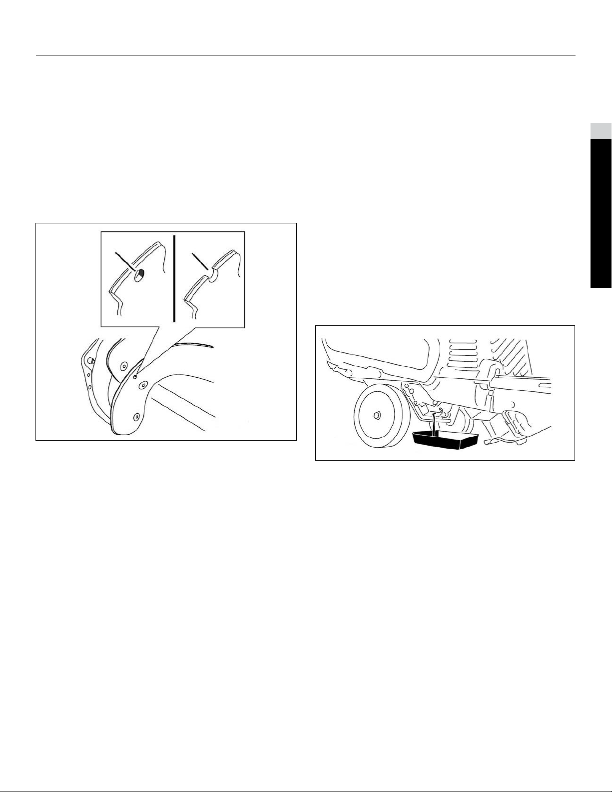
Inspecting the Rotor Blades
Service Interval
Yearly – Inspect the rotor blades and replace the rotor
blades and scraper if necessary.
Before each session, inspect the rotor blades for wear.
When a rotor blade edge has worn down to the wear
indicator hole, replace the rotor blades and the scraper
(Fig. 001).
A. The wear indicator hole is intact; you do not need to
replace the rotor blades.
B. The wear indicator hole is exposed; replace the rotor
blades and scraper.
Changing the Engine Oil
Service Interval
After the rst 2 hours yearly.
Run the engine a few minutes before changing the
oil to warm it. Warm oil ows better and carries more
contaminants.
1. Ensure that the fuel tank is not overlled and that the
fuel cap is securely in place.
2. Move the machine to a level surface.
3. Place an oil drain pan under the oil drain plug
(refer to page 217), remove the oil drain plug, and tip
the machine backward (handle down) halfway to the
ground to drain the used oil into the oil drain pan.
IMPORTANT
Do not tip the machine all the way back to the ground, or
fuel may leak out of the machine.
4. After draining the used oil, return the machine to the
operating position.
2
Specications & Maintenance
Fig. 001
5. Install the oil drain plug and tighten it securely.
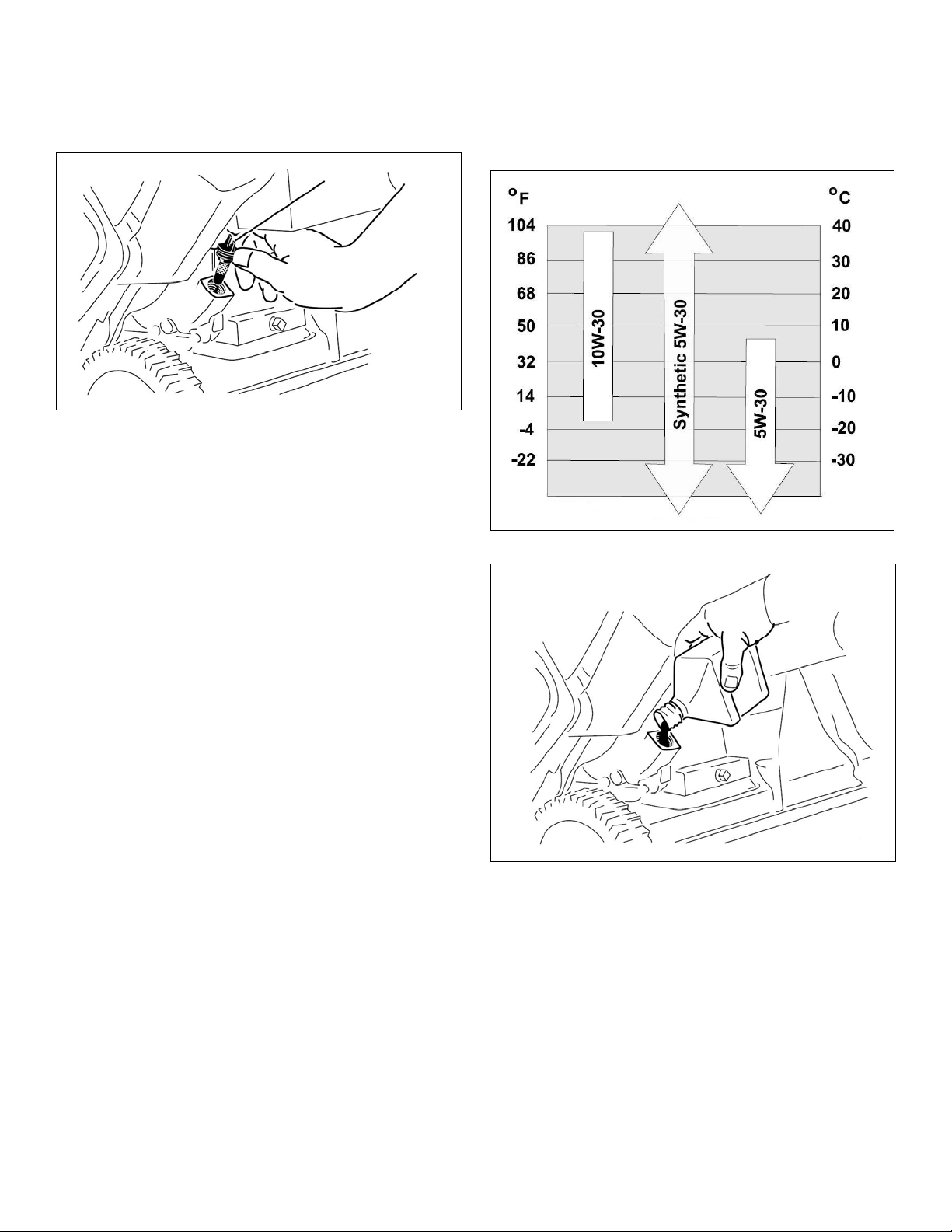
6. Clean around the oil ll cap.
7. Unscrew the oil ll cap and remove it.
8. Slowly pour oil into the oil ll hole. Wait 3 minutes,
then check the oil level on the dipstick by wiping the
dipstick clean and then inserting, but not screwing in,
the oil ll cap into the hole.
NOTE
To determine the proper oil level on the dipstick, refer
to Fig. 002.
Toro Single Stage Snow Service Manual
2-7
Page 12
SPECIFICATIONS & MAINTENANCE
A
A
B
service classication of SJ, SL, or higher.
Use Fig. 003 to select the best oil viscosity for the
outdoor temperature range expected.
C
Fig. 002
A. The oil level is at its maximum
B. The oil level is too high, remove oil from the
crank case
C. The oil level is too low, add oil to the crankcase
NOTE
You may tip the machine forward (handle up) a little to
make adding oil easier. Remember to return the machine
to the operating position before checking the oil level.
IMPORTANT
Do not tip the machine all the way forward onto its nose,
or fuel may leak out of the machine.
Max ll
12 oz. (0.35 l), type: automotive detergent oil with an API
Fig. 003
NOTE
Fill the engine crankcase with oil until the dipstick indicates
that the engine oil level is correct as shown in Fig. 002. If
you overll the engine with oil, remove the excess oil from
the drain plug into an oil drain pan.
9. Screw the oil ll cap into the oil ll hole, and hand
tighten it securely.
10. Wipe up any spilled oil.
11. Dispose of the used oil properly at a local
recycling center.
2-8
Toro Single Stage Snow Service Manual
Page 13
SPECIFICATIONS & MAINTENANCE
B
A
Servicing the Spark Plug
Service Interval
Yearly – Service the spark plug and replace it
if necessary.
Use a Toro spark plug (Part No. 1191961).
1. Stop the engine and wait for all moving parts to stop.
2. Disconnect the wire from the spark plug.
3. Clean around the spark plug.
4. Remove the spark plug from the cylinder head.
IMPORTANT
Replace a cracked, fouled, or dirty spark plug. Do not
clean the electrodes because grit entering the cylinder
can damage the engine.
2
Specications & Maintenance
5. Set the gap on the plug to 0.030” (0.76 mm)
(Fig. 004).
C
D
Fig. 004
A. Center Electrode Insulator
B. Side Electrode
C. Air Gap (not to scale)
6. Install the spark plug and torque it to 20–22 ftlb
(27–30 Nm).
7. Connect the wire to the spark plug.
Toro Single Stage Snow Service Manual
2-9
Page 14

SPECIFICATIONS & MAINTENANCE
A
B
A
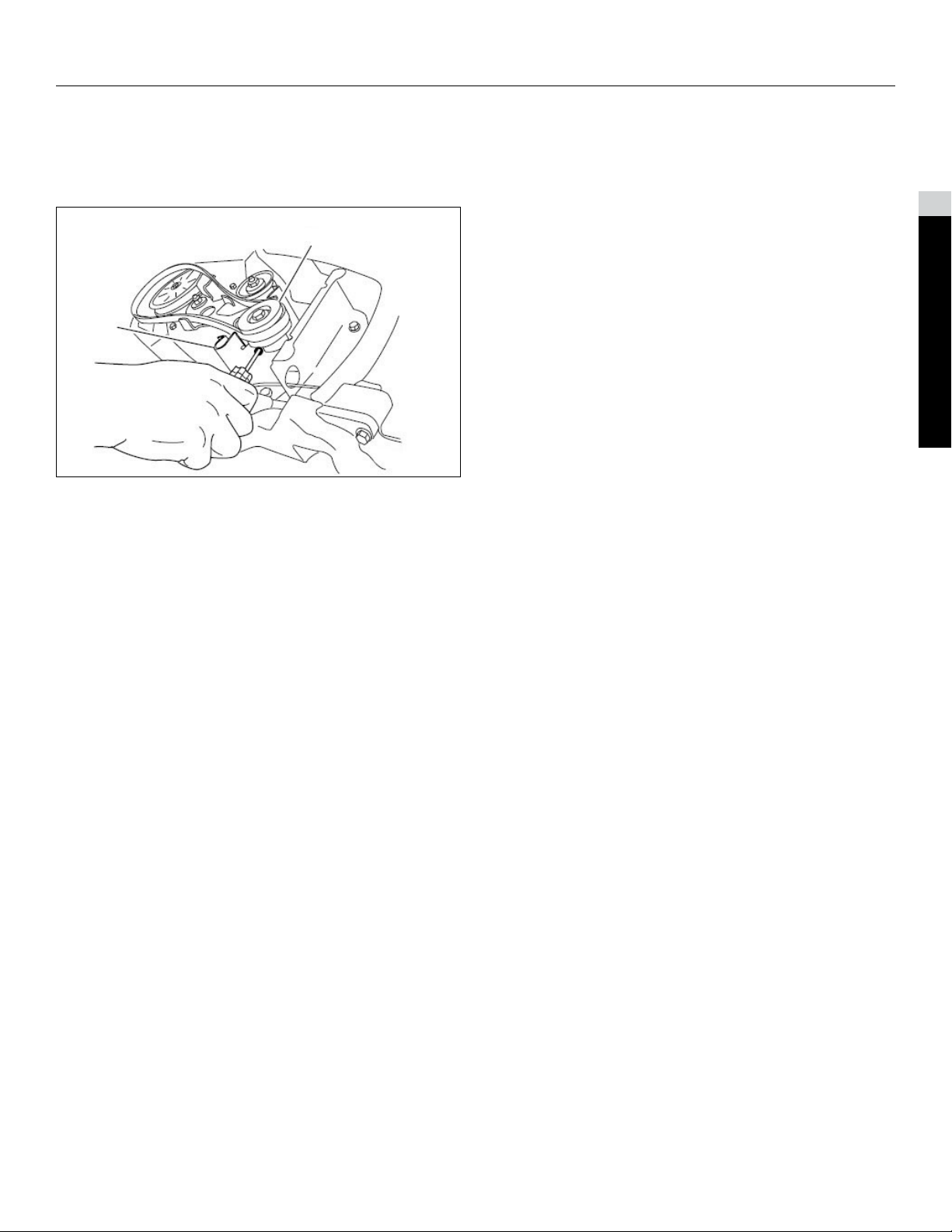
Replacing the Drive Belt
If drive belt becomes worn, oilsoaked, excessively
cracked, frayed, or otherwise damaged, replace
the belt.
1. Remove the 4 bolts that hold the drive belt cover
(Fig. 005) in place.
2. Remove the belt from the rotor pulley (Fig. 006).
C
D
E
F
G
Fig. 006
A. Rotor Pulley E. Idler Pulley
B. Idler Arm Brake F. Engine Pulley
C. Drive Belt G. Tabs on the Idler Arm
D. Idler Arm
3. Press down on the idler arm and remove the belt from
between the tab on the idler arm brake and the rotor
pulley.
Fig. 005
A. Drive Belt Cover
NOTE
The lower front corner of the drive belt cover is fastened
down with a smaller bolt, a washer, and a locknut.
NOTE
The engine pulley belt guide is very close to the pulley, and
the belt may not t through the gap.
4. Twist the belt out in front of the belt guide so that the
belt is wedged between the belt guide and the
engine pulley.
2-10
Toro Single Stage Snow Service Manual
Page 15
SPECIFICATIONS & MAINTENANCE
A
B
5. Insert a screwdriver into the hole in the belt guide as
shown in Fig. 007 and ex the belt guide toward the
rotor pulley enough to pull the belt through
the gap.
Fig. 007
A. Belt Guide
B. Engine Pulley
2
Specications & Maintenance
NOTE
Take care not to distort or damage the belt guide.
6. To install the new drive belt, reverse the
steps above.
IMPORTANT
Make sure to install the drive belt so that it sits above the
two tabs on the idler arm and below the idler arm brake
(Fig. 006).
7. Install the drive belt cover with the fasteners that you
removed in step 1.
Toro Single Stage Snow Service Manual
2-11
Page 16
SPECIFICATIONS & MAINTENANCE
A
B
Storage
Storing the Machine
WARNING
! !
• Gasoline fumes are highly ammable, explosive,
and dangerous if inhaled. If you store the product
in an area with an open ame, the gasoline fumes
may ignite and cause an explosion.
• Do not store the machine in a house (living area),
basement, or any other area where ignition sources
may be present, such as hot water and space
heaters, clothes dryers, furnaces, and other
like appliances.
• Do not tip the machine either forward or backward
with fuel in the fuel tank; otherwise, fuel may leak
out of the machine.
• Do not store the machine with its handle tipped
down onto the ground, because oil will leak into the
engine cylinder and onto the ground, and the
machine will not start or run.
1. On the last refueling of the season, add fuel stabilizer
to fresh fuel as directed by the engine manufacturer.
2. Run the engine for 10 minutes to distribute the
conditioned fuel through the fuel system.
3. While the engine is still warm, change the engine oil.
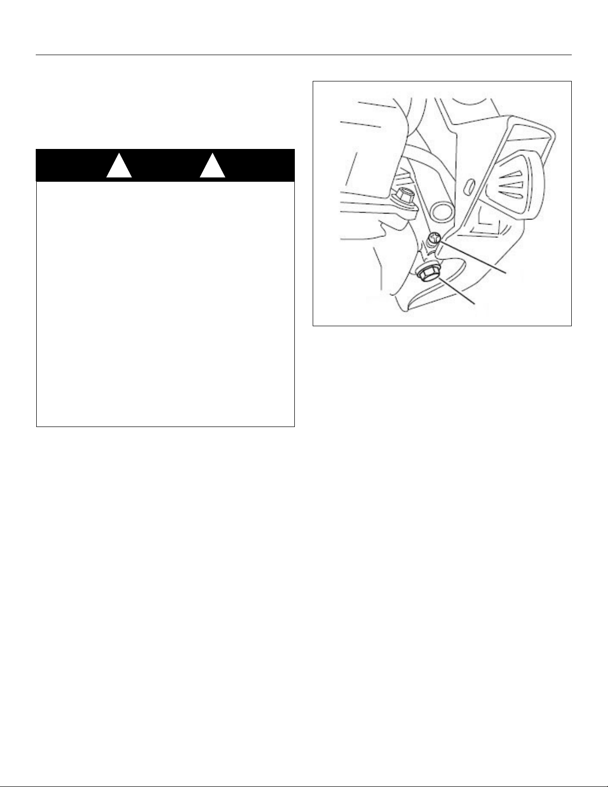
4. Drain the fuel from the tank and carburetor by
performing the following steps:
A. Loosen the fuel tank cap.
B. Unscrew, but do not remove, the small screw on
the side of the carburetor fuel bowl (Fig. 008)
until the fuel begins to drain from the carburetor.
Drain the fuel into an approved fuel container.
Fig. 008
A. Carburetor bowl bolt do not remove
B. Small screw on carburetor
C. Wait for a few minutes until the fuel has drained,
then install the fuel cap and tighten the small
screw on the carburetor.
NOTE
Use a handheld Phillips screwdriver to tighten the
carburetor screw. Overtightening the screw could strip it
and cause leaking.
5. Dispose of unused fuel properly. Recycle it according
to local codes, or use it in your automobile.
6. Remove the spark plug.
7. Squirt 2 teaspoons of oil into the spark plug hole.
8. Install the spark plug by hand and then torque it to
20–22 ftlb (27–30 Nm).
9. With the ignition key in the Off position, pull the recoil
starter slowly to distribute the oil on the inside of
the cylinder.
IMPORTANT
Do not remove the carburetor bowl bolt on the bottom of
the carburetor.
2-12
10. Disconnect the ignition key from the lanyard and store
the ignition key in a safe place.
11. Clean the machine.
Toro Single Stage Snow Service Manual
Page 17

SPECIFICATIONS & MAINTENANCE
12. Touch up chipped surfaces with paint. Sand affected
areas before painting, and use a rust preventative to
prevent the metal parts from rusting.
13. Tighten any loose fasteners. Repair or replace any
damaged parts.
14. Cover the machine and store it in a clean, dry place
out of the reach of children. Allow the engine to cool
before storing it in any enclosure.
2
Specications & Maintenance
Toro Single Stage Snow Service Manual
2-13
Page 18

SPECIFICATIONS & MAINTENANCE
Power Clear® 621 (21 Inch Models)
Maintenance
Recommended Maintenance Schedule(s)
NOTE
Determine the left and right sides of the machine from the normal operating position.
Maintenance Service Interval Maintenance Procedure
After the rst hour
After the rst 2 hours Change the engine oil.
Before each use or daily Check the engine oil level and add oil if necessary.
Yearly
Check the control cable and adjust it if necessary.
Check for loose fasteners and tighten them if necessary.
Check the control cable and adjust it if necessary.
Inspect the rotor blades and replace the rotor blades and scraper
if necessary.
Change the engine oil.
Service the spark plug and replace it if necessary.
Check for loose fasteners and tighten them if necessary.
Inspect the drive belt and replace it if necessary.
Yearly or before storage Prepare the machine for storage.
2-14
Toro Single Stage Snow Service Manual
Page 19
SPECIFICATIONS & MAINTENANCE
B
A
B
A
Adjusting the Control Cable
Checking the Control Cable
Service Interval
After the rst hour – Check the control cable and adjust it
if necessary.
Yearly – Check the control cable and adjust it if necessary.
Move the control bar back toward the handle to remove
the slack in the control cable (Fig. 009).
Adjusting the Control Cable
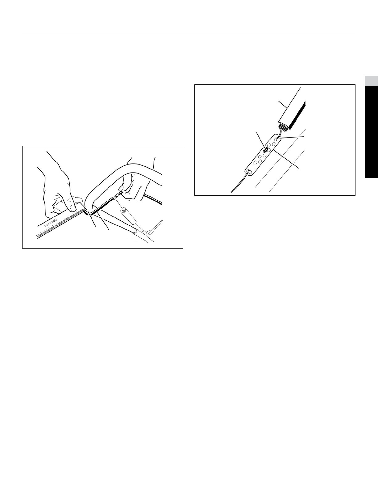
1. Slide up the spring cover and unhook the spring from
the adjuster link (Fig. 010).
C
D
Fig. 010
A. Adjuster Link B. Spring Cover
C. ZFitting D. Unhook the Spring
2
Specications & Maintenance
A. Control bar (2mm to 3mm) gap
B. 1/16” 1/8”
NOTE
Ensure that a 1/16” 1/8” (2mm to 3mm) gap exists
between the control bar and the handle (Fig. 009).
IMPORTANT
The control cable must contain some slack when you
disengage the control bar for the rotor blades to
stop properly.
Fig. 009
NOTE
You can pull up the adjuster link and cable to make
unhooking the spring easier.
2. Move the Ztting to a higher or lower hole on the
adjuster link as needed to obtain the 1/16” 1/8”
(2 mm to 3 mm) gap between the control bar and
the handle (Fig. 010).
NOTE
Moving the Ztting higher decreases the gap between the
control bar and the handle; moving it lower increases
the gap.
3. Hook the spring to the adjuster link and slide the
spring cover over the adjuster link.
4. Check the adjustment; refer to Checking the
Control Cable.
Toro Single Stage Snow Service Manual
2-15
Page 20
SPECIFICATIONS & MAINTENANCE
B
A
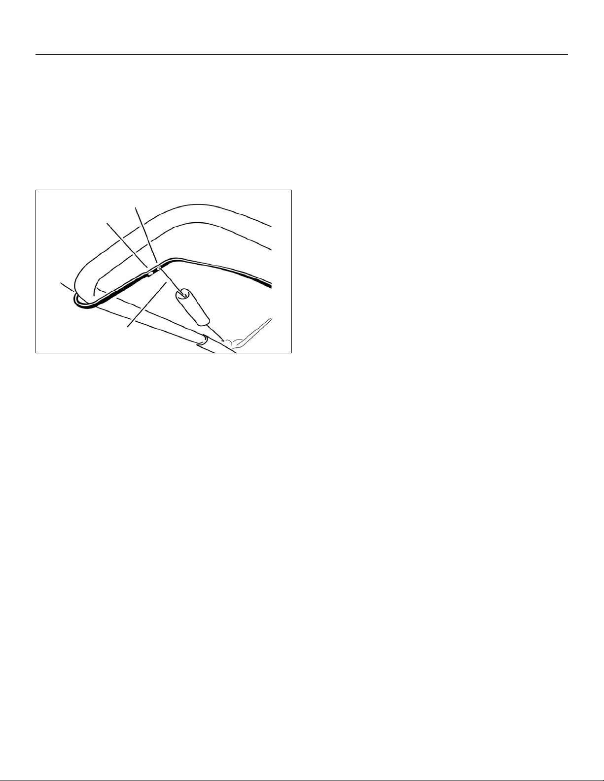
NOTE
After extended use, the drive belt may wear and lose its
proper belt tension. If the drive belt slips (continuously
squeals) under a heavy load,disconnect the spring from
the adjustor link and move the upper end of the spring to
the hole that is further from the pivot point in the control
bar (Fig. 011). Then connect the spring to the adjustor link
and adjust the control cable.
C
D
Fig. 011
A. Remove the upper end of spring from this hole
B. Insert the upper end of spring into this hole
C. Pivot point
D. Upper end of spring
NOTE
The belt may slip (squeal) in wet conditions; to dry out the
drive system, start the rotor and run it without a load for
30 seconds.
2-16
Toro Single Stage Snow Service Manual
Page 21
SPECIFICATIONS & MAINTENANCE
A
B
Inspecting the Rotor Blades
Service Interval
Yearly – Inspect the rotor blades and replace the rotor
blades and scraper if necessary.
Before each session, inspect the rotor blades for wear.
When a rotor blade edge has worn down to the wear
indicator hole. Replace the rotor blades and the
scraper (Fig. 012).
Changing the Engine Oil
Service Interval
• After the rst 2 hours
• Yearly
Run the engine a few minutes before changing the
oil to warm it. Warm oil ows better and carries more
contaminants.
1. Siphon the fuel from the fuel tank into an approved fuel
container, or run the engine until it stops.
2. Move the machine to a level surface.
3. Place an oil drain pan under the oil drain plug, remove
the oil drain plug, and tip the machine backward and
drain the used oil in the oil drain
pan (Fig. 013).
2
Specications & Maintenance
Fig. 012
A. The wear indicator hole is intact; you do not need to
replace the rotor blades.
B. The wear indicator hole is exposed; replace the
rotor blades.
Fig. 013
4. After draining the used oil, return the machine to the
operating position.
5. Install the oil drain plug and tighten it securely.
6. Clean around the oil ll cap (Fig. 014).
Toro Single Stage Snow Service Manual
2-17
Page 22
SPECIFICATIONS & MAINTENANCE
A
7. Unscrew the oil ll cap and remove it (Fig. 014).
Fig. 014
A. Oil ll cap
8. With the machine in the operating position, carefully
pour oil into the oil ll hole. Wait 3 minutes for the
oil to settle and add enough to bring it to the point of
overow (Fig. 016).
9. Screw the oil ll cap into the oil ll hole, and hand
tighten it securely.
Fig. 015
NOTE
You may tip the machine forward (handle up) to make
adding oil easier. Remember to return the machine to the
operating position before checking the oil level.
IMPORTANT
Do not tip the machine all the way forward onto its nose, or
fuel may leak out of the machine.
Max ll: 20 oz. (0.6 l), type: automotive detergent oil with
an API service classication of SJ, SL, or higher.
Use Fig. 015 to select the best oil viscosity for the outdoor
temperature range expected.
Fig. 016
10. Wipe up any spilled oil.
11. Dispose of the used oil properly at a local
recycling center.
2-18
Toro Single Stage Snow Service Manual
Page 23

SPECIFICATIONS & MAINTENANCE
A
B
B
A
Servicing the Spark Plug
Service Interval
Yearly – Check the spark plug and replace it if necessary.
Use a NGK BPR6ES or Champion RN9YC spark plug or
equivalent.
1. Stop the engine and wait for all moving parts to stop.
2. Rotate the discharge chute so that it faces forward.
3. Remove the discharge chute, the discharge chute
handle, and the chute seal by removing the 3 large
screws and one small screw (Fig. 017).
C
D
4. Remove the 4 screws that secure the shroud
(Fig. 018).
C
D
2
Specications & Maintenance
A. Fuel Tank Cap D. Small Screw
B. Large Screws (3) E. Chute Seal
C. Discharge Chute
E
Fig. 017
Fig. 018
A. Screw (4) C. Spark Plug
B. Shroud D. SparkPlug Wire
5. Remove the fuel tank cap.
6. Remove the shroud (Fig. 018).
7. Install the fuel tank cap.
8. Disconnect the wire from the spark plug.
9. Clean around the spark plug.
10. Remove the spark plug from the cylinder head.
IMPORTANT
Replace a cracked, fouled, or dirty spark plug. Do not
clean the electrodes because grit entering the cylinder can
damage the engine.
Toro Single Stage Snow Service Manual
2-19
Page 24

SPECIFICATIONS & MAINTENANCE
B
A
A
B
11. Set the gap on the plug to 0.030” (0.76mm)
(Fig. 019).
C
D
Fig. 019
A. Center Electrode Insulator
B. Side Electrode
C. Air Gap (not to scale)
12. Install the spark plug and torque it to 20–22 ftlb
(27–30 Nm).
13. Connect the wire to the spark plug.
NOTE
Ensure that the breather tube is routed above the spark
plug wire as shown in Fig. 020.
14. Remove the fuel tank cap.
15. Install the shroud with the screws you removed in
step 4.
NOTE
Ensure that the upper and lower shrouds t together in the
side grooves.
16. Install the fuel tank cap.
17. Install the chute seal, the discharge chute, and the
discharge chute handle onto the machine using the
hardware you removed in step 3.
NOTE
The small screw goes through the small hole in the chute
seal at the front of the discharge chute opening.
Fig. 020
A. Breather tube B. Carburetor drain bolt
2-20
Toro Single Stage Snow Service Manual
Page 25

SPECIFICATIONS & MAINTENANCE
B
A
A
B
Replacing the Drive Belt
If drive belt becomes worn, oilsoaked, excessively
cracked, frayed, or otherwise damaged, replace the belt.
1. Remove the drive belt cover by removing the 3 bolts
as shown in Fig. 021.
J
I
H
G
F
E
D
C
Fig. 021
A. Drive Belt Cover G. Rotor Shaft
B. Bolt (3) H. Brake Spring
C. Rotor Pulley Bolt (unhook from idler
D. Curved Washer arm here)
E. Rotor Pulley I. Idler Pulley
F. Drive Belt J. Engine Pulley
2. Unhook the brake spring from the idler arm to release
the belt tension (Fig. 021).
3. Remove the screw and curved washer that holds
the rotor pulley (Fig. 021).
4. Remove the rotor pulley and the drive belt
(Fig. 021).
5. Install the new drive belt, routing it as shown in
(Fig. 022).
2
Specications & Maintenance
C
D
Fig. 022
A. Brake Spring (install on C. Engine Pulley
idler arm here) D. Rotor Pulley
B. Idler Pulley
NOTE
Route the new drive belt rst around the engine pulley,
then the idler pulley, and nally around the loose rotor
pulley positioned just above the rotor shaft (Fig. 022).
6. Install the rotor pulley onto the rotor shaft
(Fig. 022).
7. Install the curved washer and the rotor pulley bolt and
tighten them securely (Fig. 022).
NOTE
The concave side of the curved washer goes against the
outside of the pulley.
8. Install the brake spring onto the idler arm
(Fig. 022).
9. Install the drive belt cover with the bolts you removed
in step 1.
NOTE
Ensure that the drive belt is properly adjusted and
operating; refer to “Checking the Control Cable” and
“Adjusting the Control Cable.”
Toro Single Stage Snow Service Manual
2-21
Page 26

SPECIFICATIONS & MAINTENANCE
A
A
A
Adjusting the Quick
Shoot™ Control
If there is more than 1/2” (13mm) of slack in the
Quick Shoot cable (Fig. 023) or the discharge chute does
not rotate left and right in equal angles, adjust the Quick
Shoot control cables.
Fig. 023
A. 1/2” (13mm) maximum slack
2. Position the Quick Shoot control between the two
arrows located on the right hand side of the upper
handle (Fig. 025).
Fig. 025
A. Arrows
3. Rotate the discharge chute so that it faces straight
ahead and the arrow on the back of the discharge
chute aligns with the arrow on the shroud (Fig. 026).
1. Loosen the two Quick Shoot control cable clamps
(Fig. 024).
A. Cable Clamps
Fig. 024
Fig. 026
2-22
Toro Single Stage Snow Service Manual
Page 27

SPECIFICATIONS & MAINTENANCE
A
A
4. Hold the discharge chute in the straightahead
position, pull the lower cable casing downward until
you remove the slack in the cable, and tighten the
screw on the lower cable clamp securely (Fig. 027).
A. Lower cable casing
2
Specications & Maintenance
Fig. 027
5. Pull the upper cable casing forward until you remove
the slack in the cable, and tighten the screw on the
upper cable clamp securely (Fig. 028).
Fig. 028
A. Upper cable casing
NOTE
Do not overtension the cables. If the cables are
overtensioned, the Quick Shoot will be hard to operate.
Toro Single Stage Snow Service Manual
2-23
Page 28

SPECIFICATIONS & MAINTENANCE
NOTES
2-24
Toro Single Stage Snow Service Manual
Page 29

CHAPTER 3 - CHASSIS
Power Clear® 18 Inch Snowthrower Main Frame – Lower ....................3-2
Power Clear® 18 Inch Snowthrower Main Frame – Housing .................3-3
Power Clear® 18 Inch Snowthrower Main Frame – Shroud ...................3-4
Power Clear® 18 Inch Snowthrower Main Frame – Upper Handle ........3-5
Power Clear® 18 Inch Snowthrower Main Frame – Lower ....................3-6
Power Clear® 21 Inch Snowthrower Main Frame – Housing .................3-7
Power Clear® 21 Inch Snowthrower Main Frame – Chute .......... 3-8 to 3-9
Power Clear® 21 Inch Snowthrower Main Frame – Handles ...............3-10
Power Clear® 21 Inch Snowthrower Main Frame – Power Shoot ........3-11
Power Clear® 21 Inch Snowthrower Main Frame – Shroud .................3-12
Power Clear® 21 Inch Snowthrower Main Frame – Quick Shoot .........3-13
Power Clear® 21 Inch Snowthrower Main Frame – Quick Shoot .........3-14
18 Inch Shroud Removal .....................................................................3-15
21 Inch Shroud Removal .....................................................................3-16
Quick Shoot Contols ............................................................................3-17
3
Chassis
Toro Single Stage Snow Service Manual
3-1
Page 30

CHASSIS
Power Clear® - 18 Inch Snowthrower
Main Frame – Lower
A
B
C
A. Side plate RH
B. Side plate LH
C. Belt Cover
D. Model/Serial Decal
3-2
D
Fig. 001
Toro Single Stage Snow Service Manual
Page 31

Power Clear® - 18 Inch Snowthrower
B
C
Main Frame – Housing
CHASSIS
3
Chassis
A
Fig. 002
A. Lower Handle
B. Scraper
C. Chute Retainer
Toro Single Stage Snow Service Manual
3-3
Page 32

CHASSIS
B
C
Power Clear® - 18 Inch Snowthrower
Main Frame – Shroud
A. Shroud Assembly
B. Lower Shroud LH
C. Lower Shroud RH
A
Fig. 003
3-4
Toro Single Stage Snow Service Manual
Page 33

Power Clear® - 18 Inch Snowthrower
B
Main Frame – Upper Handle
A
G
CHASSIS
F
3
Chassis
E
A. Clutch Bail E. Spring Cover
B. Handle Knob F. Upper Handle Assembly
C. Cable Clutch Adjuster G. Recoil Handle
D. Clutch Spring
Toro Single Stage Snow Service Manual
Fig. 004
3-5
Page 34

CHASSIS
B
C
Power Clear® - 18 Inch Snowthrower
Main Frame – Lower
A
A.ChuteDeectorAssembly
B. Discharge Chute
C. Chute Handle
3-6
Fig. 005
Toro Single Stage Snow Service Manual
Page 35

Power Clear® - 21 Inch Snowthrower
B
C
D
E
Main Frame – Housing
F
CHASSIS
H
3
Chassis
A
A. Scraper Blade E. Extension Spring
B. Auger Housing F. Lower Chute
C. Frame Brace G. Belt Cover
D. Clutch Cable Guide H. Model/Serial Decal
Toro Single Stage Snow Service Manual
G
Fig. 006
3-7
Page 36

CHASSIS
B
Power Clear® - 21 Inch Snowthrower
Main Frame – Chute
D
E
A
F
Fig. 007
A. Chute Ring E. Chute Seal Ring
B. Discharge Chute Assembly F. Chute Ring Gear
C.ChuteDeector
D. Chute Control Handle
3-8
Toro Single Stage Snow Service Manual
Page 37

Power Clear® - 21 Inch Snowthrower
B
C
D
Main Frame – Chute
A
L
F
G
CHASSIS
M
3
Chassis
K
E
J
I
H
A.DeectorTrigger E.Chute I. DetentPaw M.SealRingChute
B.ChuteDeector F. PinionGear J.ChuteSupportRing
C.RatchetDeectorHinge G.PinionBracket K.ChuteRingGear
D.DeectorSeal H.CableRetainer L.ChuteHandle
Toro Single Stage Snow Service Manual
Fig. 008
3-9
Page 38

CHASSIS
B
D
Power Clear® - 21 Inch Snowthrower
Main Frame – Handles
J
A
I
E
F
H
G
A. Upper Handle Assembly E. Clutch Cable Adjuster I. Rope Guide
B.ControlBail F. HandleLock J.RecoilHandle
C. Spring Cover G. Lower Handle
D. Clutch Extension Spring H. Handle Knob
3-10
Fig. 009
Toro Single Stage Snow Service Manual
Page 39

Power Clear® - 21 Inch Snowthrower
Main Frame – Power Shoot
E
A
CHASSIS
F
3
Chassis
J
A. Slider Handle RH E. Slider Pulley I. Trigger
B.ShortChuteCable F. SliderTrack J.CableBracket
C. Long Chute Cable G. Chute Lock Plate
D. Pulley Cover H. Slider Handle LH
G
I
H
Fig. 010
Toro Single Stage Snow Service Manual
3-11
Page 40

CHASSIS
B
Power Clear® - 21 Inch Snowthrower
Main Frame – Shroud
A
I
H
G
F
E
A. Gas Cap E. Lower Shroud H. Primer Bulb
B.ShroudAssembly F. ChokeKnob I. ExhaustBafe
C. Tank Seal G. On/Off Switch
D. Fuel T ank
3-12
Fig. 011
Toro Single Stage Snow Service Manual
Page 41

Power Clear® - 21 Inch Snowthrower
Main Frame – Quick Shoot
Illustration 1
CHASSIS
Illustration 2
3
Chassis
Toro Single Stage Snow Service Manual
Illustration 4
Illustration 3
Fig. 012
3-13
Page 42

CHASSIS
Power Clear® - 21 Inch Snowthrower
Main Frame – Quick Shoot
Illustration 5
Illustration 6
Illustration 7
3-14
Fig. 013
Toro Single Stage Snow Service Manual
Page 43

CHASSIS
B
A
A
A
A
B
B
18 Inch Shroud Removal
1. Remove key from ignition. Remove the screws
securing the lower shrouds (A). Remove the right and
left lower shrouds (B) (Fig. 014).
Fig. 014
2. Remove the belt cover. Disconnect the clutch cable
from the belt guide. Slide the cable through
the housing (Fig. 015).
3. Remove the shroud screws and fuel cap and remove
the shroud. Reinstall fuel cap (Fig. 016).
Fig. 016
3
Chassis
Toro Single Stage Snow Service Manual
Fig. 015
3-15
Page 44

CHASSIS
21 Inch Shroud Removal
1. Remove key from ignition. Remove the bolts that hold
the discharge chute to the chute seal ring
(Fig. 017).
Fig. 017
2. Remove the single screw holding the chute seal ring
Remove the ring (Fig. 018).
3. Remove the two rear screws holding the shroud to
the chassis. Remove the two front screws holding the
shroud to the chassis (Fig. 019).
Fig. 019
4. Remove the shroud (Fig. 020).
3-16
Fig. 020
Fig. 018
Toro Single Stage Snow Service Manual
Page 45

CHASSIS
A
Quick Shoot Contols
1. Remove the bolt holding the quick chute gear
assembly to the chute housing (Fig. 021).
Fig. 021
2. Remove the complete assembly. Remove pinion
spacer sleeve (A) Fig. 022).
3. With a pliers, compress the cable locks and remove
the cables from the pinion bracket (Fig. 023).
Fig. 023
4. Turn the gear assembly over and remove the
cable retainer (Fig. 024).
3
Chassis
Toro Single Stage Snow Service Manual
Fig. 024
Fig. 022
3-17
Page 46

CHASSIS
5. With the cable retainer removed, note the direction
of the cable wrapping (Fig. 025).
Fig. 025
6. To re-wrap the cables, refer to the following steps
and the illustrations on pages 3-13 and 3-14. With
the pinion gear facing up, the black cable is routed
furthest to the bottom of the gear. Insert the barrel
end of the cable into the hole and secure the cable
under the tab in the gear (Fig. 026).
7. Wrap the cable around the bottom of
the spool (Fig. 027).
Fig. 027
8. When the cable is fully wrapped, it should look
like this (Fig. 028).
3-18
Fig. 028
Fig. 026
Toro Single Stage Snow Service Manual
Page 47

CHASSIS
9. Insert the barrel of the grey cable into its slot in the
gear. Secure the cable under the tabs in the gear
(Fig. 029).
Fig. 029
10. Route the cable around the top of the spool (Fig. 030).
12. Slide the gear into the pinion bracket and secure the
cable locks (Fig. 032).
Fig. 032
13. Align the quick chute control and the discharge chute
asoutlinedinthespecicationsandmaintenance
chapter. Insert the pinion spacer sleeve and insert
the pinion and bracket assembly as shown. Tighten
bolt to 8 ft-lbs (11 Nm) (Fig. 033).
3
Chassis
Fig. 030
11. When the cables are routed correctly the cables and
gear should look like this (Fig. 031).
Fig. 031
Toro Single Stage Snow Service Manual
Fig. 033
NOTE
Do not overtighten!
3-19
Page 48

CHASSIS
NOTES
3-20
Toro Single Stage Snow Service Manual
Page 49

CHAPTER 4 - POWER PROPEL SYSTEM
Power Clear® - 18 Inch Snowthrower Rotor Assembly .......4-2
Power Clear® - 18 Inch Snowthrower Drive System ...........4-3
Power Clear® - 21 Inch Snowthrower Rotor Assembly .......4-4
Power Clear® - 21 Inch Snowthrower Drive System ...........4-5
18 Inch Rotor Removal & Replacement .............................4-6
21 Inch Rotor Removal & Replacement .............................4-8
Paddle Replacement (All Models) ....................................4-10
18 Inch Scraper Removal & Replacement .......................4-11
21 Inch Pivoting Scraper Removal & Replacement..........4-12
4
Power Propel System
Toro Single Stage Snow Service Manual
4-1
Page 50

POWER PROPEL SYSTEM
A
B
Power Clear® - 18 Inch Snowthrower
Rotor Assembly
C
D
E
F
A. Side Plate Cap E. Rotor Blade
B. Ball Bearing F. Rotor Assembly
C. Bearing Flange
D. Thrust Washer
4-2
Fig. 001
Toro Single Stage Snow Service Manual
Page 51

POWER PROPEL SYSTEM
A
B
Power Clear® - 18 Inch Snowthrower
Drive System
D
C
F
E
G
4
Power Propel System
A. Engine Pulley E. Idler Arm
B. Ribbed V-Belt F. Rotor Pulley Assembly
C. Belt Guide G. Idler Pulley
D. Clutch Cable
Toro Single Stage Snow Service Manual
Fig. 002
4-3
Page 52

POWER PROPEL SYSTEM
A
B
Power Clear® - 21 Inch Snowthrower
Rotor Assembly
A. Rotor Blade
B. Rotor
4-4
Fig. 003
Toro Single Stage Snow Service Manual
Page 53

Power Clear® - 21 Inch Snowthrower
A
B
Drive System
POWER PROPEL SYSTEM
F
E
D
4
Power Propel System
C
A. Rotor Pulley Assembly E. Idler Arm
B. Drive Belt F. Engine Pulley
C. Idler Pulley G. Pinion Bracket
D. Clutch Cable H. Cable Retainer
Toro Single Stage Snow Service Manual
Fig. 004
4-5
Page 54

POWER PROPEL SYSTEM
A
B
B
A
B
B
A
A
18 Inch Rotor Removal & Replacement
1. Remove the belt cover. Remove the drive belt (A)
and the rotor pulley (B) (Fig. 005).
Fig. 005
2. Remove the three rotor bearing screws on the belt
side of the housing (Fig. 006).
3. Remove the three rotor bearing screws on the
opposite side of the housing (Fig. 007).
Fig. 007
4. Remove three bolts holding the side plate to the
rotor housing (A). Loosen the wheel bracket
bolts (B) (Fig. 008).
4-6
Fig. 006
Fig. 008
Toro Single Stage Snow Service Manual
Page 55

POWER PROPEL SYSTEM
A
5. Pull the side plate out slightly to gain clearance to
get the rotor out (Fig. 009).
Fig. 009
6. Lift rotor assembly out of the housing (Fig. 010).
8. Slide rotor back into the housing. Reinstall the bolts
and torque to 8 ft-lbs (11 Nm) (Fig. 012).
Fig. 012
9. Re-install the rotor pulley and drive belt. Torque rotor
pulley bolt to 8 ft-lbs (11 Nm) (Fig. 013).
7. Replace rotor parts as required (Fig. 011).
4
Power Propel System
Fig. 010
Fig. 013
10. Re-install the belt cover. Torque bolts to 8 ft-lbs
(11 Nm).
Toro Single Stage Snow Service Manual
Fig. 011
4-7
Page 56

POWER PROPEL SYSTEM
B
A
21 Inch Rotor Removal & Replacement
1. Remove the belt cover. Remove the drive belt (A)
and the rotor pulley (B) (Fig. 015).
Fig. 015
2. Remove the three rotor bearing screws on the belt
side of the housing (Fig. 016).
3. Remove the three rotor bearing screws on the
opposite side of the housing (Fig. 017).
Fig. 017
4. Remove the rotor assembly from the housing.
(Fig. 018).
4-8
Fig. 016
Fig. 018
Toro Single Stage Snow Service Manual
Page 57

POWER PROPEL SYSTEM
5. Remove the bearing spacer bolt and bearing spacer.
6. Removebearingsandanges.Replacerotorparts
as required (Fig. 019).
Fig. 019
7. Re-install the bearing spacer and bolt. Torque bolt to
20 ft-lbs (27 Nm) (Fig. 020).
8. Re-install the rotor assembly into the housing.
Re-install the rotor bearing screws. Torque to
8 ft-lbs (11 Nm) (Fig. 021).
Fig. 021
9. Re-install the drive belt and rotor pulley. Torque the
rotor pulley bolt to 8 ft-lbs (11 Nm) (Fig. 022).
4
Fig. 020
Power Propel System
Fig. 022
10. Re-install the belt cover. Torque the bolts to 8 ft-lbs
(11 Nm).
Toro Single Stage Snow Service Manual
4-9
Page 58

POWER PROPEL SYSTEM
Paddle Replacement (All Models)
1. With the rotor assembly removed from the housing,
remove the Torx™ fasteners (Fig. 023).
Fig. 023
2. Remove the two inner bolts holding the paddle to the
rotor (A) (Fig. 024).
3. Remove the paddle. Be sure to remove the rotor
blade spacers (A) and install them in the
new paddles (Fig. 025).
Fig. 025
4. Install new paddles and install rotor assembly back
into the housing.
4-10
Fig. 024
Toro Single Stage Snow Service Manual
Page 59

POWER PROPEL SYSTEM
18 Inch Scraper Removal & Replacement
1. Remove the three bolts attaching the scraper to
the frame.
2. Install a new scraper. Torque bolts to 16 in-lbs
(0.184 kg-m) (Fig. 26).
Fig. 026
4
Power Propel System
Toro Single Stage Snow Service Manual
4-11
Page 60

POWER PROPEL SYSTEM
21 Inch Pivoting Scraper Removal & Replacement
1. Remove the spring from each side of the scraper
(Fig. 027)
Fig. 027
2. Remove the bolts from each side of the scraper
(Fig. 028).
3. Remove the scraper from housing (Fig. 029).
Fig. 029
4. Insert new scraper. Re-install springs and bolts.
Torque bolts to 20 ft-lbs (27 Nm) (Fig. 30).
Toro Single Stage Snow Service Manual
Fig. 030
Fig. 028
4-12
Page 61

CHAPTER 5 - ENGINE MOUNTING
Power Clear® - 18 Inch Snowthrower Engine Mounting ........5-2
Power Clear® - 21 Inch Snowthrower Engine Mounting ........5-3
Engine Removal 18 Inch Models ...........................................5-4
Engine Installation 18 Inch Models ........................................5-5
Engine Removal 21 Inch Models ...........................................5-6
Engine Installation 21 Inch Models ........................................5-8
5
Engine Mounting
Toro Single Stage Snow Service Manual
5-1
Page 62

ENGINE MOUNTING
A
B
Power Clear® - 18 Inch Snowthrower
Engine Mounting
C
D
A. Tank Seal
B. Woodruff Key
C. Choke Lever
5-2
Fig. 001
Toro Single Stage Snow Service Manual
Page 63

Power Clear® - 21 Inch Snowthrower
A
B
Engine Mounting
E
ENGINE MOUNTING
D
A. LC168FS Engine E. Choke Link Knob
B. PTO Engine Plate
C. Side Engine Support
D. Engine Support
C
5
Engine Mounting
Fig. 002
Toro Single Stage Snow Service Manual
5-3
Page 64

ENGINE MOUNTING
AAA
A
A
A
Engine Removal 18 Inch Models
1. Remove the shroud as outlined in Chapter 3.
2. Remove the belt cover and remove belt as outlined
in chapter 2.
3. Remove the engine pulley bolt and remove pulley
(Fig. 003).
Fig. 003
4. From the underside of the chassis, remove the two
engine mounting bolts (A) (Fig. 004).
5. Remove the four engine mounting bolts that connect
the engine to the side plate (A) (Fig. 005).
Fig. 005
6. Remove the engine from the chassis (Fig. 006).
5-4
Fig. 006
Fig. 004
For engine service information,
see Single Stage Snow Engine
Service Manual LC154FS/
LC154FDS (87cc), PN 492-9233
or LC168F/LC168FD (163 cc),
PN 492-9230
Toro Single Stage Snow Service Manual
Page 65

A
A
Engine Installation 18 Inch Models
ENGINE MOUNTING
1. Insert the engine into the chassis. Install the four
engine mounting bolts that connect the engine to the
side plate (A). Torque to 14-18 ft-lbs (19-25 Nm)
(Fig. 007).
Fig. 007
2. From the underside of the chassis, install the two
engine mounting bolts (A). Torque to 14-18 ft-lbs
(19-25 Nm) (Fig. 008).
3. Install the engine pulley. Torque bolt to 19 ft-lbs
(26 Nm) (Fig. 009).
Fig. 009
4. Install the belt as outlined in chapter 2. Install belt
cover. Install shroud as outlined in chapter 2.
Fig. 008
5
Engine Mounting
Toro Single Stage Snow Service Manual
5-5
Page 66

ENGINE MOUNTING
Engine Removal 21 Inch Models
1. Remove the shroud as outlined in chapter 3.
2. Empty the fuel from the fuel tank into a suitable
container. Remove the fuel hose and remove the
fuel tank.
3. Remove the screw from the underside of the choke
knob and remove the choke knob (Fig. 010).
5. Route the recoil rope through the lower shroud and
knot the rope (Fig. 012).
Fig. 012
6. Disconnect the primer hose from the primer bulb and
remove the ignition wires from the ignition switch.
(Fig. 013).
4. Untie the knot on the recoil handle (Fig. 011).
Fig. 010
Fig. 013
Fig. 011
5-6
Toro Single Stage Snow Service Manual
Page 67

ENGINE MOUNTING
A
A
AAA
A
7. From the underside of the chassis, remove the two
engine mounting bolts (A) (Fig. 014).
Fig. 014
8. Remove the belt cover and belt as outlined in
chapter 2 (Fig. 015).
11. Remove the four engine mounting bolts that secure
the engine to the engine plate (A) (Fig. 017).
Fig. 017
12. Remove the engine from the chassis (Fig. 018).
9. Remove the engine pulley.
Fig. 015
10. On some models, the engine pulley has two set
screws. One is an allen head set screw and the
other is a bolt. Be sure to loosen both set screws
before attempting removal (Fig. 016).
Fig. 016
5
Fig. 018
Engine Mounting
Toro Single Stage Snow Service Manual
5-7
Page 68

ENGINE MOUNTING
A
A
A
A
A
A
Engine Installation 21 Inch Models
1. Insert the engine into the chassis. Install the four
engine mounting bolts that secure the engine to the
engine plate (A). Torque to 14-18 ft-lbs (19-25 Nm)
(Fig. 019).
Fig. 019
2. From the underside of the chassis, install the two
engine mounting bolts (A). Torque to 14-18 ft-lbs
(19-25 Nm) (Fig. 020).
3. Install the engine pulley. If the unit has a bolt holding
the engine pulley on, torque the bolt to 19 ft-lbs (26
Nm). If the unit has set screws, slide the pulley onto
the shaft and install the belt. With a straight edge,
align the pulley with the rotor pulley so the belt is
straight.Tighten set screws (Fig. 021).
Fig. 021
4. Connect the primer hose to the primer bulb and plug
the ignition wires into the ignition switch (Fig. 022).
5-8
Fig. 020
Fig. 022
Toro Single Stage Snow Service Manual
Page 69

5. Untie the recoil rope knot and route the rope through the
lower shroud. Install the recoil handle and knot the rope
(Fig. 023).
Fig. 023
6. Slide the choke wire through the lower shroud and
install the choke knob and screw (Fig. 024).
ENGINE MOUNTING
Fig. 024
7. Install the fuel tank and connect the fuel line.
8. Install the belt cover and shroud as outlined in chapter 2.
5
Engine Mounting
Toro Single Stage Snow Service Manual
5-9
Page 70

ENGINE MOUNTING
NOTES
5-10
Toro Single Stage Snow Service Manual
Page 71

Page 72

Residential Products
2014 Power Clear® 418/621
2014 Power Clear® 418/621
Service Manual
Service Manual
Form Number 492-9340
 Loading...