

Page 1
P220G Series Plastic Valve
P220G Series Plastic Valve
Installation and Operating Instructions
Installation and Operating Instructions
Introduction
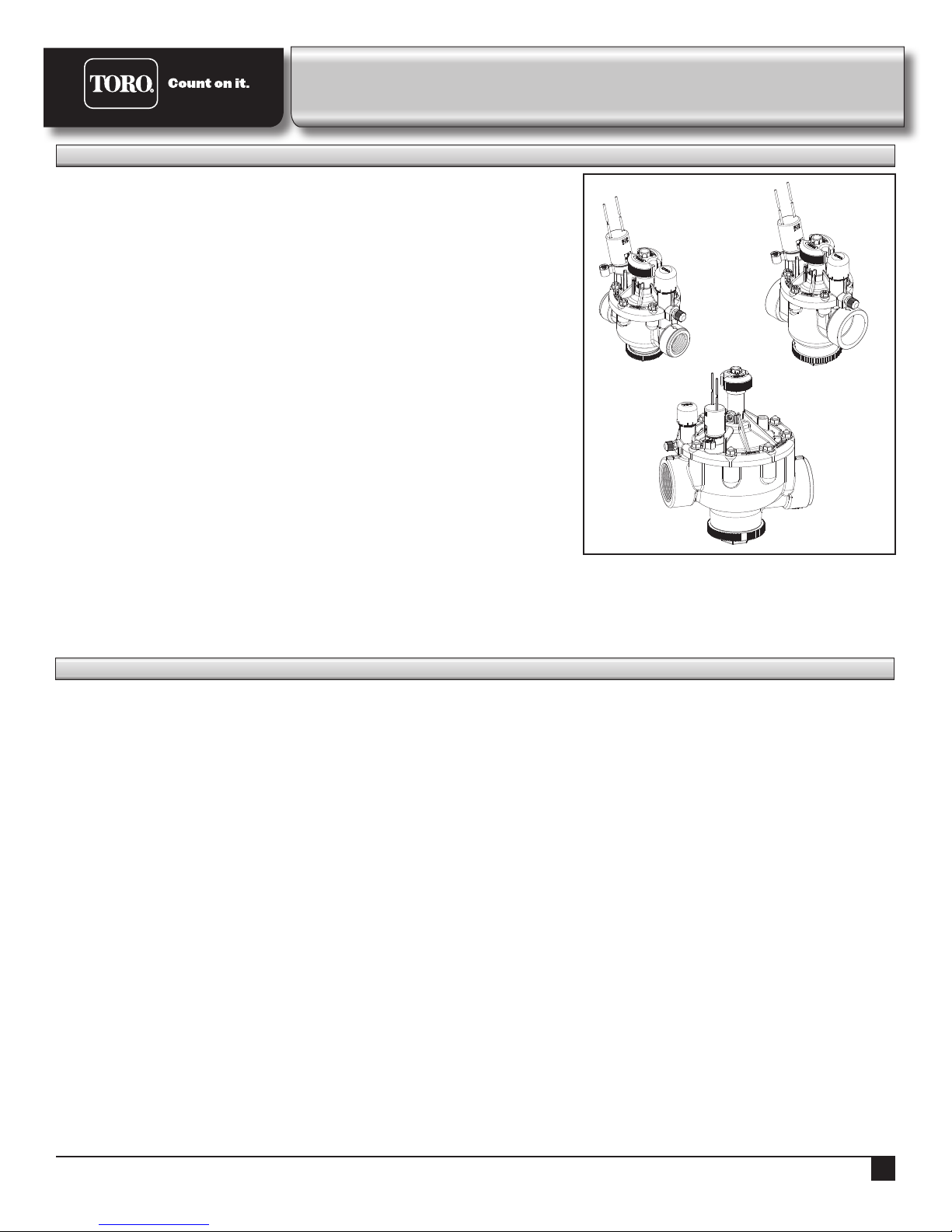
e P220G Series valves are available in two operation and
two activation types.
Operation
• P220G is intended for golf and commercial applications with
normal water conditions.
• P220GS “Scrubber Valve” models are intended for applications with dirty
water conditions. ese models include Toro’s patented “ACT” system
with a rotating turbine that continuously cleans the stainless steel screen
during operation.
P220 (G,S)
1”
P220 (G,S)
1½”
Activation
AC powered - For satellite systems, the 24 VAC Spike Guard solenoid
P220 (G,S)
2”
provides 20,000 volt lightning protection to minimize down time and service
costs. Moreover, it draws less than half the wattage of traditional solenoids for
a lower long-term cost of ownership.
DC powered - For GDC 2-wire systems, a DC-latching solenoid reduces the
system wire load to lower initial system cost. It is activated by a momentary
pulse “on” and “o”, meaning there is no continuous power draw, providing a
lower long-term cost of ownership.
e P220G EZReg pressure regulator adjusts easily with the micro-adjust dial
and indicator to provided constant downstream pressure between 5-100 psi (,34-6,9 bar).
Note: e P220G valve should be installed below grade in a valve box or vault (see page 2) to provide service access and vandal
resistance. e valve installation site should be readily accessible by grounds maintenance personnel and well clear of hardscape
features, cart paths, and foot trac areas.
Specifications
Conguration
• globe and angle forward ow
• plastic and stainless steel construction
• 1” (25 mm), 1 ½” (40 mm),
2” (50 mm)
NPT and BSP models
• electric actuation
• pressure regulating
Dimensions
1” 6¾” H x 3⅝” W
25 mm 171 mm H x 92 mm W
1½” 7¼” H x 3⅝” W
40 mm 184 mm H x 92 mm W
2” 7½” H x 6⅛” W
50 mm 241 mm H x 156 mm W
Operating Pressure Range
• Inlet - 1” and 1½” models:
10-220 psi (,69-15,2 bar)
• Inlet - 2” models:
20-220 psi (1,39 - 15,2 bar)
• Outlet: 5-100 +/- 3 psi
(,34-6,89 bar +/- ,2 bar)
• minimum inlet / outlet dierential:
10 psi (,69 bar)
• burst pressure safety rating:
750 psi (51,7 bar)
SpikeGuard solenoid
(for satellite control systems)
24 VAC, 50/60 Hz
Inrush - 0.12 amps
Holding - 0.10 amps
Diaphragm
EPDM diaphragm for improved
chlorine resistance
Manual Flow Control
adjustable to zero ow
Manual Bleed
enables manual valve operation
bleeds o water internally downstream
EZReg Pressure Regulator
• compact, precision-dial design
• regulates during automatic and
manual operation
• serviceable while valve is pressurized
• poppet valve (Schrader-type) for
downstream pressure verication
Flow Range
1” (25 mm) 5-40 gpm
19-151 lpm
1½” (40 mm) 30-100 gpm
114-379 lpm
2” (50 mm) 80-180 gpm
303-681 lpm
DC-latching solenoid
(for GDC 2-Wire control systems)
momentary low-voltage pulse
1
Page 2
Installation
• Note the ow direction arrow in the side of the
valve body and install accordingly.
• e valve can be installed at any angle without
aecting operation.
• Use direct-burial irrigation control wire for
connection from the controller to valves.
• Leave a 12” (305 mm) wire expansion loop at
each valve location on long-run wire lengths.
• Waterproof wire splice connectors are
absolutely essential for proper electric control
system operation. Follow the installation
instructions provided by the connector
manufacturer for optimum performance.
* Distances specied under the following
conditions: minimum voltage: 20 VAC, amperage:
0.12A, operating pressure: 150 psi (10,3 bar).
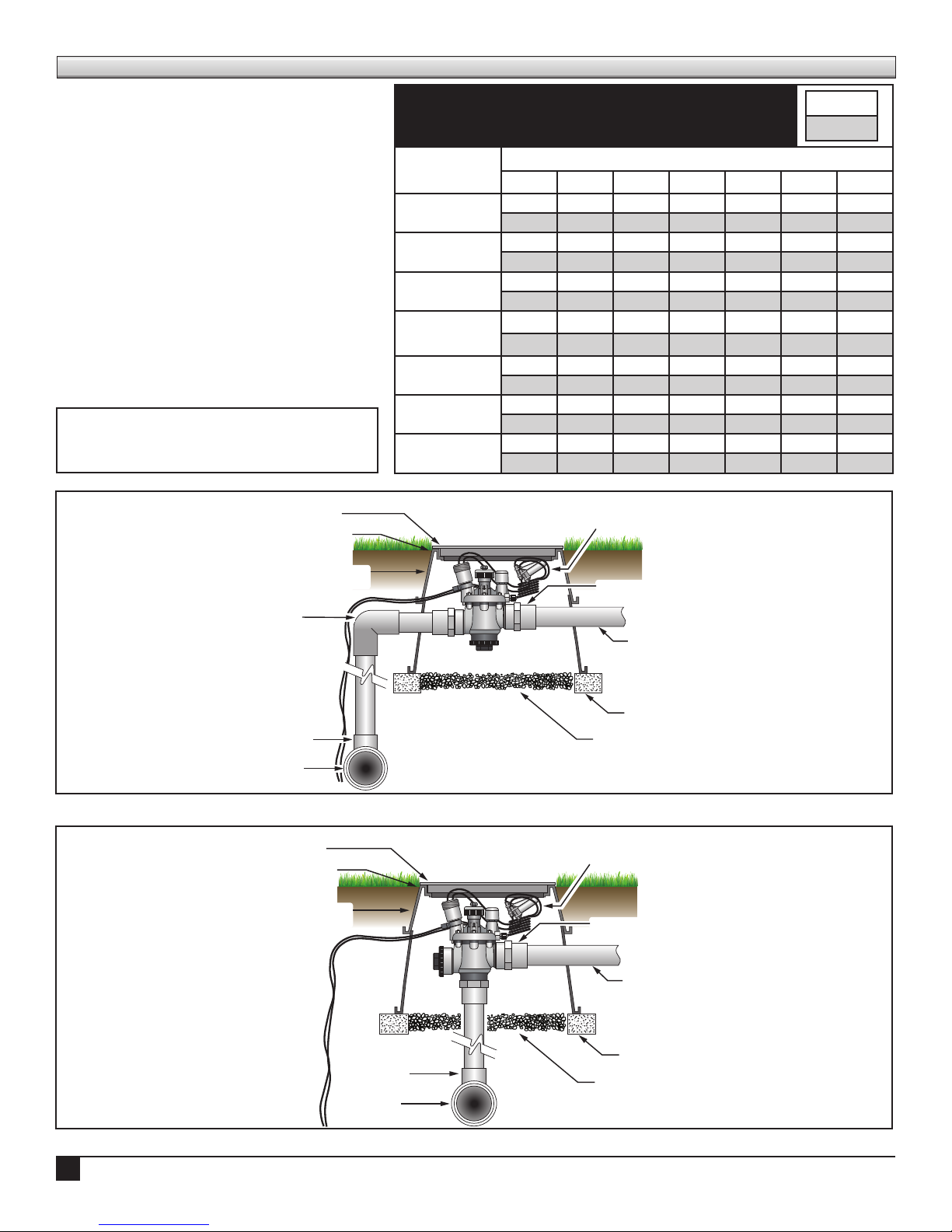
Chart showing the maximum one-way wire distance
between controller and valve solenoid *
Common Wire
Gauge Size
18
16
14
18 16 14 12 10 8 6
2040 2520 2940 3280 3540 3720 3860
622 768 896 1000 1079 1134 1177
2520 3260 4000 4660 5220 5620 5920
768 994 1219 1420 1591 1713 1804
2940 4000 5180 6360 7420 8300 8960
896 1219 1579 1939 2262 2530 2731
Control Wire Gauge Size
3280 4660 6360 8240 10100 11800 13180
12
10
8
6
1000 1420 1939 2512 3078 3597 4017
3540 5220 7420 10100 13180 16060 18770
1079 1591 2262 3078 4017 4895 5721
3720 5260 8300 11800 16060 20800 25540
1131 1603 2530 3597 4895 6340 7785
3860 5960 8960 13180 18700 25540 33080
1177 1817 2731 4017 5700 7785 10083
feet
meters
TORO TVB MODEL
VALVE BOX & COVER
FINISHED GRADE
TORO TVB MODEL
VALVE BOX EXTENSION
(if required)
ELBOW
MAIN LINE
TEE
OR ELBOW
TORO TVB MODEL
VALVE BOX & COVER
FINISHED GRADE
TORO TVB MODEL
VALVE BOX EXTENSION
(if required)
CONTROL WIRES WITH 12”
SERVICE COIL AND WATERPROOF
WIRE SPLICE CONNECTORS
MALE ADAPTER (TYP.)
LATERAL LINE
CONTINUOUS BRICK SUPPORT
CLEAN AGGREGATE
(305 mm)
side inlet installation
CONTROL WIRES WITH 12”
SERVICE COIL AND WATERPROOF
WIRE SPLICE CONNECTORS
MALE ADAPTER (TYP.)
(305 mm)
2
MAIN LINE
TEE
OR ELBOW
LATERAL LINE
CONTINUOUS BRICK SUPPORT
CLEAN AGGREGATE
bottom inlet installation
Page 3
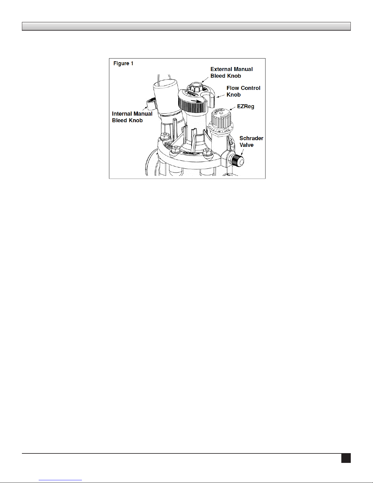
Valve Adjustment
Flow Control
e ow control is used to reduce the ow and pressure to
valve outlet. By turning the
ow control handle clockwise,
the ow will be gradually
reduced to zero.
Note: e ow control
should remain in the fully
open position. Use only for
emergency shut o or for valve
zone ne-tuning.
Internal Bleed Knob Downstream pressure
regulation maintained
e internal manual bleed
system is used to manually
operate the valve. Turning
the internal bleed knob
(located beneath the solenoid)
counterclockwise allows water
to bleed downstream from the diaphragm chamber. Internal
pressure is relieved from the top of the diaphragm, allowing
the valve to open. Turning the bleed knob clockwise until
tight shuts o the discharge enabling pressure to build within
the diaphragm chamber, causing the valve to close.
External Manual Bleed Knob (ush mode)
e external manual bleed knob, located on top of the ow
control handle, is used for system ushing. Turning this knob
counterclockwise allows water in the diaphragm chamber to
vent to atmosphere, creating maximum opening power and
debris ushing action. is operation bypasses the regulator
and opens the valve fully, regardless of regulator setting. In
addition, the metering rod (attached to the external bleed
knob) can be easily removed for cleaning as necessary.
EZReg Adjustment
An accurate, adjustable dial, coupled with a forward-ow
valve design, allows the P220
series valve with EZReg to
regulate downstream water
pressure with precision.
It’s easy and simple to use
and requires only 10 PSI
dierential pressure to operate.
e EZReg will operate
during powered and manual
valve operation using internal
manual bleed.
To adjust the downstream
pressure, remove the cover
from the regulator dial, then
turn the dial until the pointer
is on the desired pressure of
5-100 PSI (EZR-100).
Note: Due to the microadjustment feature of the EZReg, the dial requires 10
revolutions for complete regulation range.
Operate the valve (electrically or manually). Check the
ow control to conrm that it is in the fully open position.
Adjust the regulator dial if necessary for optimum sprinkler
operation.
To conrm the downstream pressure using a pressure gauge,
remove the cap from the Schrader-type valve located directly
below the EZReg. Attach a Toro pressure gauge (Model 995-
51) to the Schrader-type valve for a direct reading. Adjust the
EZReg dial as necessary for the desired pressure.
Note: e valve will remain watertight in the closed position
if removal of the EZReg assembly is required.
3
Page 4
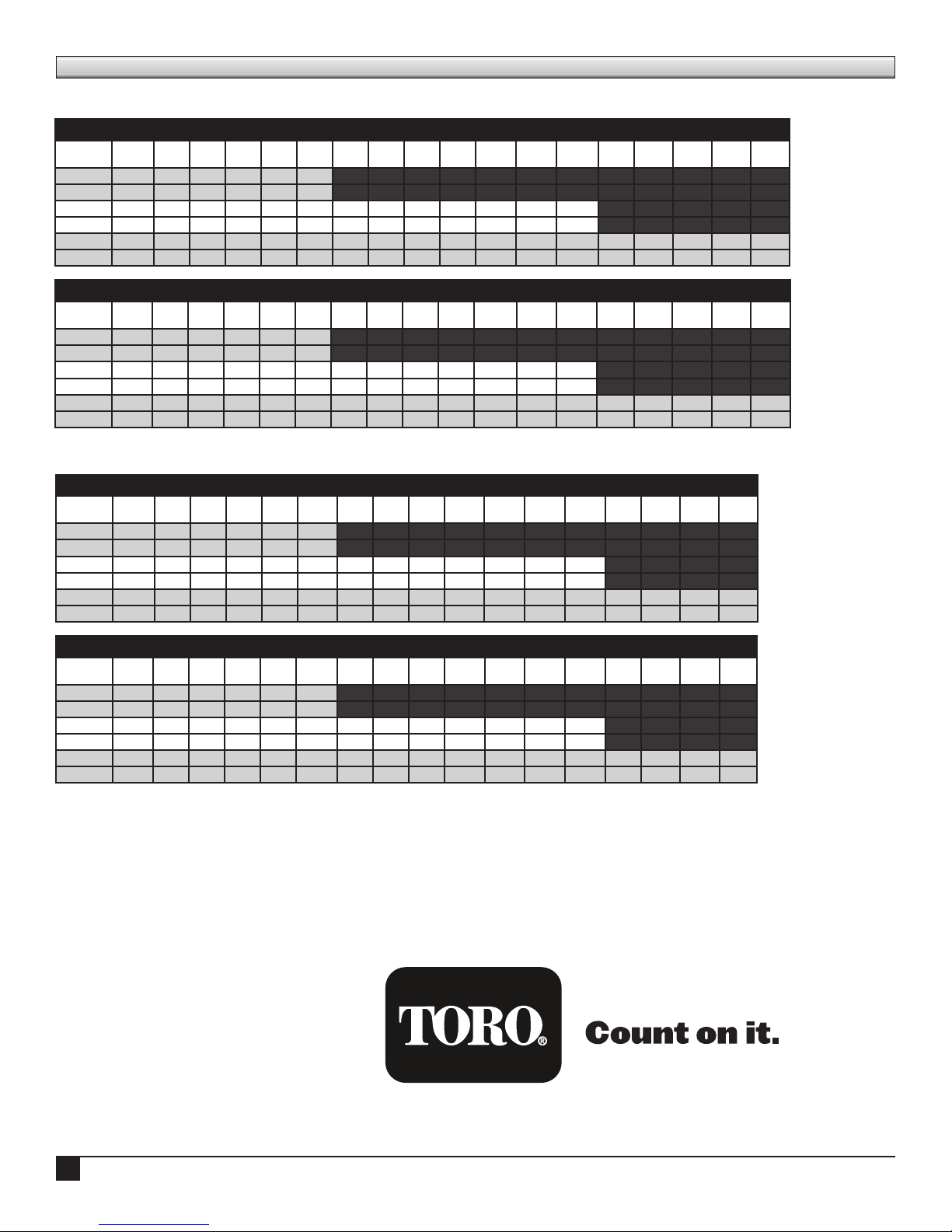
Friction Loss Charts
P220G Standard Valves
Friction Loss in PSI
GPM
Type 5 10 20 30 40 50 60 70 80 90 100 110 120 130 140 150 180
1”
1 1/2”
2”
Friction Loss in BAR
LPM
25 mm
40 mm
50 mm
globe 4.00 4.20 3.20 4.10 7.20
angle 4.00 4.20 3.10 2.70 4.80
globe 1.60 2.30 3.60 5.20 7.00 9.20 11.20 13.60 16.40
angle 1.30 1.60 2.80 4.00 5.50 7.10 8.90 10.90 13.50
globe 2.10 2.70 3.30 4.00 4.80 5.60 6.50 7.50 8.70
angle 1.20 1.60 2.00 2.40 2.80 3.30 3.90 4.40 5.20
Type 19 38 76 114 152 190 227 265 303 341 379 417 455 493 531 569 682
globe 2.76 2.89 2.20 2.82 4.96
angle 2.76 2.89 2.14 1.86 3.31
globe 1.10 1.58 2.48 3.58 4.82 6.34 7.72 9.37 11.30
angle 0.90 1.10 1.93 2.76 3.79 4.89 6.13 7.51 9.30
globe 1.45 1.86 2.27 2.76 3.31 3.86 4.48 5.17 5.99
angle 0.83 1.10 1.38 1.65 1.93 2.27 2.69 3.03 3.58
P220G Scrubber Valves
Friction Loss in PSI
GPM
1”
1 1/2”
2”
Type 5 10 20 30 40 50 60 70 80 90 100 110 120 130 140 150
globe 4.63 4.74 3.10 6.05 10.75
angle 4.14 4.64 2.54 5.53 9.46
globe 1.14 1.56 2.85 4.36 6.28 8.57 11.20 14.03 17.20 20.46
angle 0.95 1.51 2.28 3.69 5.29 6.97 9.26 11.80 14.60 17.40
globe 3.57 4.62 5.33 6.80 8.20 9.02 10.46 11.61
angle 2.79 3.50 4.41 5.62 6.39 7.35 8.81 9.37
Friction Loss in BAR
LPM
25 mm
40 mm
50 mm
Type 19 38 76 114 152 190 227 265 303 341 379 417 455 493 531 569
globe 3.19 3.27 2.14 4.17 7.41
angle 2.85 3.20 1.75 3.81 6.52
globe 0.79 1.07 1.96 3.00 4.33 5.90 7.72 9.67 11.85 14.10
angle 0.65 1.04 1.57 2.54 3.64 4.80 6.38 8.13 10.06 11.99
globe 2.46 3.18 3.67 4.69 5.65 6.21 7.21 8.00
angle 1.92 2.41 3.04 3.87 4.40 5.06 6.07 6.46
© 2016 The Toro Company • Irrigation Division • 1-877-345-8676 Form Number 373-0883 Rev. A
4
 Loading...